Embed Size (px)
Citation preview
1
Operating
instructions
Original operating instructions
Date of: 18.07.2013
Desktop CNC-/3D-System
STEPCRAFT 300 / 420 / 600
Manufacturer:
STEPCRAFT GmbH & Co. KG
Kalkofen 6
58638 Iserlohn
Germany
Phone: +49 (0) 2371 – 974 85 74
Facsimile: +49 (0) 2371 – 953 75 00
E-Mail: [email protected]
Internet-Adresse: www.stepcraft-systems.com
Please read these instructions before the first commissioning of your machine
thoroughly and only commission the machine when you are sure that you
understood everything.
Keep these instructions always nearby your machine.
Before each commissioning it is necessary to check if the machine is working
technically perfect and if it is a technically perfect status.
3
CONTENTS
1 General notes ..................................................................................................................5
1.1 Information and explanations for the operating instructions ......................................5
1.2 Description of the machine .......................................................................................5
1.3 Intended use ............................................................................................................6
2 Safety ..............................................................................................................................6
2.1 General notes...........................................................................................................6
2.2 Responsibility of the operator and working safety .....................................................6
2.3 Personal protective equipment .................................................................................7
2.4 Environmental conditions .........................................................................................7
2.5 Commissioning of the system control / milling spindle ..............................................7
2.6 Operator ...................................................................................................................8
2.7 Emergency-Stop switch ............................................................................................8
2.8 Remaining risk .........................................................................................................8
3 Structure and function .....................................................................................................9
3.1 Designation and functions of the component parts ...................................................9
4 Commissioning .............................................................................................................. 10
4.1 Installing the machine ............................................................................................. 10
4.2 Environmental conditions ....................................................................................... 10
4.3 Electrical connection of the machine ...................................................................... 10
4.4 Optional accessory ................................................................................................. 11
4.4.1 Drilling / Milling spindle .................................................................................... 11
4.4.2 Additional accessory ....................................................................................... 11
4.5 Machine table ......................................................................................................... 11
5 Machine operation ......................................................................................................... 11
5.1 Operator ................................................................................................................. 11
5.2 Work piece ............................................................................................................. 12
5.3 System-guided tools ............................................................................................... 12
5.3.1 Drilling / milling spindle .................................................................................... 12
5.3.2 Cutting knife .................................................................................................... 12
5.3.3 Hot cutter ........................................................................................................ 12
5.3.4 Engraving point / plotter pen............................................................................ 13
5.3.5 3D-Printer head ............................................................................................... 13
5.4 Emergency-stop switch .......................................................................................... 13
4
5.5 Operation of the system / operating elements ........................................................ 13
5.6 Optional accessory ................................................................................................. 13
6 Technical data ............................................................................................................... 14
6.1 Dimensions and weight .......................................................................................... 14
6.2 Drive of the machine .............................................................................................. 14
6.3 Other specifications ................................................................................................ 14
6.4 Spare parts ............................................................................................................ 15
6.5 Pin assignment charts of unit control / optional modules ........................................ 15
6.5.1 Parallel port LPT-adapter (X1) ......................................................................... 15
6.5.2 Connector external signals / Sub-D 15 (X2) ................................................... 16
6.5.3 Connector 4th axis / Sub-D 9 (X101) ............................................................... 16
7 Transportation / storage ................................................................................................ 17
7.1 Transportation ........................................................................................................ 17
7.2 Packaging .............................................................................................................. 17
7.3 Storage .................................................................................................................. 17
8 Maintenance .................................................................................................................. 17
8.1 Safety ..................................................................................................................... 17
8.2 Maintenance works ................................................................................................ 17
9 Malfunctions .................................................................................................................. 18
9.1 Behavior in case of malfunctions ............................................................................ 18
10 Annex ............................................................................................................................ 19
10.1 Type plate .............................................................................................................. 19
10.2 Copyright ................................................................................................................ 19
10.3 Warranty and liability .............................................................................................. 19
10.4 Disposal via municipal collecting points .................................................................. 19
10.5 RoHS, 2002/95/EG ................................................................................................ 19
10.6 EC-Declaration of conformity .................................................................................. 20
5
1 GENERAL NOTES
1.1 INFORMATION AND EXPLANATIONS FOR THE OPERATING INSTRUCTIONS
This manual serves to make you familiar with a desktop CNC-/3D-system and to impart you all
necessary information which you require in order to be able to operate the machine safely and
professionally.
This manual is applicable for the desktop CNC-/3D-systems STEPCRAFT 300, STEPCRAFT 420 and
STEPCRAFT 600, hereafter referred to as STEPCRAFT.
Please completely read this manual before the first commissioning of your machine.
In order to minimize the risks of injury and/or material damages please only commission the machine
and the corresponding control when you are sure that you have completely understood these
instructions!
Please contact us for any further questions. Please find our contact data on page -3- of these
instructions.
Please always keep these instructions nearby the machine. You should always have them readily to
hand when you want to look up something.
Please only use this machine according to its intended use (refer to item 1.3).
We cannot be held liable for persons or material damages which are caused by using the machine
other than the intended use, handling which does not comply with the common use of a CNC machine
or if safety regulations are not obeyed (refer to item 2).
In case of lacking maintenance (refer to item 8) and/or wrong operation of the individual components
your warranty claims are omitted.
We reserve the right to perform future technical enhancements on the machine and its components.
1.2 DESCRIPTION OF THE MACHINE
The STEPCRAFT machines are desktop CNC-/3D-systems for machining wood, plastics or
nonferrous metals. The systems are based on a specially developed aluminum extrusion containing
numerous functions (e.g. guiding, drive, protection against dust, etc.). It is very stable and torsion-
resistant due to its angular shape.
The machine has three axes which are offset by 90°. In this way it is possible to travel to any point
within the working range. Each axis is equipped with a step motor and a reference switch. The step
motor precisely drives the mobile axes elements by means of a threaded spindle. It is possible to use
the control in order to adjust the position of the axis with the help of the reference switch.
The machine table consists of a High Pressure Laminat (HPL) with a thickness of 8.0 mm. You can fix
the work piece directly on the table with the clamping system delivered.
The STEPCRAFT-System consists of different central components. In order to use a ready-to-operate
CNC machine the following additional components are required:
1. Control / main board (integrated, see connection panel on the back of the machine) with USB-
or parallel module
2. System-guided tools with a shank diameter of 43.0 mm / 1.69 inch, e.g. a milling spindle, or
any other tool with a shank diameter of less than 43 mm / 1.69 inch with a suitable clamping
adapter (not enclosed)
6
3. Control software with cycle direction output signals, e.g. WinPC-NC or Mach3 (not enclosed).
In the USB variant the software WinPC-NC Starter is enclosed.
4. Suitable PC (not enclosed)
5. Connection cable (enclosed)
You can optionally retrofit the machine/control e.g. with a fourth axis. This allows the turning of the
work piece.
Please find further information for optional accessory under item 5.6 of these instructions.
1.3 INTENDED USE
The STEPCRAFT machine series is designed for private users (e.g. model-makers) and piece
productions or productions of small series in the industrial area. It is not suitable for the production of
large series or to integrate it in production lines.
The torsion-resistant structure allows to process plastic materials, wood and non-ferrous metals.
The used milling spindle should not exceed the power of 500 watts.
You should work using milling cutters with a diameter of up to 3.0 mm. If possible immediately absorb
the chips during production.
2 SAFETY
2.1 GENERAL NOTES
Please completely read this manual before the first commissioning of your machine! Any person
operating this machine must have read these instructions!
In order to minimize the risks of injury and/or material damages only operate the machine and the
corresponding control when you are sure that you have completely understood the instructions!
Please do not hesitate to contact us for any further questions. Please find our contact data on page -3-
of these instructions.
Please always keep these instructions nearby the machine. You should always have them readily to
hand when you want to look up something.
Please only use this machine according to its intended use (refer to item 1.3). If the machine is not
used as intended there is a risk for persons and of material damages!
It is not allowed to modify and/or retrofit the machine unless this has been expressively authorized by
us in individual cases.
The STEPCRAFT is designed and constructed according to the currently applicable state-of-the-art.
2.2 RESPONSIBILITY OF THE OPERATOR AND WORKING SAFETY
When you operate the machine you should have the minimum age of 14 years and be technically
experienced.
Being the operator you are responsible that you have read and understood all relevant operating
instructions and to keep them nearby the machine.
You have to make sure that you operate the machine only when it is in a technically proper status.
7
The emergency-stop switch and if applicable other safety equipment must always be well attainable
and operable.
Being the operator you have to wear the personal protective equipment described under item 2.3
when you work on the machine.
In particular when performing setting works on the machine on the control or on the milling spindle
please disconnect the machine from the mains!
Always make sure to have sufficient clearance to the mobile parts (guiding, milling cutters, shafts) and
never grasp with your hand into the machine. This may result in severe injuries!
Never hold the work piece (in order to measure it to process it or for any other purposes) while the
machine is running. There is a high risk of injury!
Never hold the work piece to be processed only with the hand but always firmly clamp the work piece.
Otherwise there is a high risk of injury!
Depending on the field of application of the machine (private or industrial use) please observe the
correspondingly applicable regulations for occupational safety, safety and accident prevention as well
as environmental protection.
2.3 PERSONAL PROTECTIVE EQUIPMENT
- Safety goggles (to protect the eyes against chips flying off at high speed, etc.)
- Hearing protection (to protect the ears against loud noises)
- Protective gloves (to protect the hands against cuts, abrasions, etc.)
- Furthermore do not wear any clothes which might get caught in the machine (ties, scarves,
shawl, wide sleeves, etc.) and do not wear any jewelry in particular no long chains and rings.
2.4 ENVIRONMENTAL CONDITIONS
The machine is only suitable to be operated inside!
Position the machine on a solid plane substructure in order that is stands safely and can neither slip
nor tilt over.
Make sure that there is sufficient space around the machine in order that you can work comfortably
and that the machine can fully extend to its traveling paths. Also keep sufficient clearance to possibly
nearby positioned machines.
Provide for sufficient illumination of the machine site and the working place surrounding the machine.
Place the PC which controls the machine nearby the machine so that you can have an eye on both.
All instructions for the machine and its components must be nearby.
2.5 COMMISSIONING OF THE SYSTEM CONTROL / MILLING SPINDLE
In order to safely and professionally commission the electronic control of the system the milling spindle
and possibly additionally built-in components please imperatively read the operating instructions of the
individual components completely before the first commissioning of the whole system.
Check if the individual components are perfectly connected with each other before the first
commissioning and in regular intervals later on.
Furthermore, check before each use of your machine if it is supplied with current and if required if the
compressed air is working perfectly.
8
2.6 OPERATOR
The person operating the machine should be not less than 14 years old and technically experienced.
All persons operating the machine must have completely read and understood all relevant operating
instructions.
Each operator must get familiar with the electronic control of the machine as well as with the used
control software before the first use of the machine.
Each operator must have personal protective equipment.
Each operator must operate the machine and its components with due prudence and due expertise
which is necessary for the use of CNC controlled milling machines.
2.7 EMERGENCY-STOP SWITCH
The emergency-stop switch is located at the front side of the machine (refer to the schematics under
item 3.1 of these operating instructions).
The Emergency-Stop is released by pressing the switch.
In this way the power supply of the control is interrupted. Furthermore, the control software receives
the signal to stop the working process. The machine stops immediately.
ATTENTION! The emergency-stop switch can only affect the standstill of all components if they are
connected.
This is ensured if you use the milling spindles and the controller made by STEPCRAFT.
If you use any third party products such as e.g. another controller you are responsible yourself to
connect the Emergency-Stop switch professionally with your controller. Otherwise there is a risk for
persons and material damages!
Also if you would like to use a system-guided tool like a milling spindle of another supplier which is
equipped with a separate ON/OFF switch and is NOT controlled via the PC you have to make sure
that it is professionally connected to the emergency-stop switch.
If you do not observe this it will continue running even if you actuate the emergency-stop switch. Also
here there is a risk for persons or material damages!
Please do not hesitate to contact us for any further questions!
Please find further information regarding the Emergency-Stop switch under item 5.4 of these
instructions.
2.8 REMAINING RISK
In spite of all preventive measures there is always a remaining risk for persons and material.
Therefore, operate the machine and its components circumspectly and carefully!
Make sure that you are working concentrated and that you are not tired.
Do not operate the machine and its components if you are under the influence of medication, alcohol
or drugs.
9
3 STRUCTURE AND FUNCTION
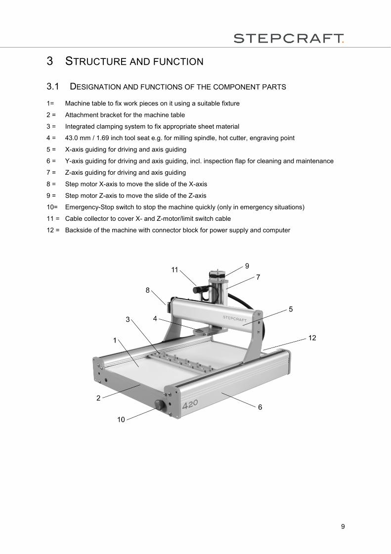
3.1 DESIGNATION AND FUNCTIONS OF THE COMPONENT PARTS
1= Machine table to fix work pieces on it using a suitable fixture
2 = Attachment bracket for the machine table
3 = Integrated clamping system to fix appropriate sheet material
4 = 43.0 mm / 1.69 inch tool seat e.g. for milling spindle, hot cutter, engraving point
5 = X-axis guiding for driving and axis guiding
6 = Y-axis guiding for driving and axis guiding, incl. inspection flap for cleaning and maintenance
7 = Z-axis guiding for driving and axis guiding
8 = Step motor X-axis to move the slide of the X-axis
9 = Step motor Z-axis to move the slide of the Z-axis
10= Emergency-Stop switch to stop the machine quickly (only in emergency situations)
11 = Cable collector to cover X- and Z-motor/limit switch cable
12 = Backside of the machine with connector block for power supply and computer
10
4 COMMISSIONING
4.1 INSTALLING THE MACHINE
The machine must be positioned on an absolutely level even working table so that it stands safely and
can neither slip nor tilt over.
All mobile parts of the machine must have sufficient space in order that they can be moved without
collisions.
The cable duct of the system-guided tool e.g. the milling spindle must be designed in a way that the
spindle cable is not being clamped between the guide ways of the machine.
It is necessary to well attain and operate the machine.
It is in particular necessary to reach the Emergency-Stop switch at any time; it must not be obstructed.
Provide for sufficient illumination of the machine site and the working place surrounding the machine.
Place the PC which controls the machine nearby the machine so that you can have an eye on both.
4.2 ENVIRONMENTAL CONDITIONS
Install the machine in a closed room.
Keep the environmental temperature of the machine dust-free. Too high dust loading can cause
damages on the system.
The humidity should be within normal limits for humidity content inside. Protect the machine against
wetness and humidity.
The perfect environmental temperature for the system is from 18°C to 25°C, from 64°F to 77°F
respectively.
In particular protect the controller against overheating by avoiding direct sun radiation or indirect
heating up nearby a radiator.
4.3 ELECTRICAL CONNECTION OF THE MACHINE
The connection of the stepping motors, the end switches and the emergency-stop switch has to
processed conform to the construction manual enclosed.
The low-voltage plug of the power supply has to be connected to the connection socket of the unit
control at the backside of the machine.
The computer will be connected to the desktop 3D-system with an USB- or parallel connection cable.
The necessary socket is located at the backside of the machine, too. Depending on the variant of
interface module there is either an USB- or a parallel socket.
The LED lights of the unit control are visible from the outside. The LED lights flash in case of:
Control light Impact
LED1 System ok / power amplifier switched on / emergency-stop switch switched off
LED2 Power on / 5V DC
11
4.4 OPTIONAL ACCESSORY
If you use any accessory which was not made or sold by STEPCRAFT please check if it is compatible
with your system before the first use.
In case of doubts please contact the corresponding manufacturer, if required.
4.4.1 DRILLING / MILLING SPINDLE
Please read the operating instructions of the drilling / milling motor!
In addition please observe the following items:
The used drilling / milling motor must not exceed the power of 500 watts.
The machine is equipped with a 43 mm / 1.69 inch tool holder with a thickness of 10 mm / 0.39 inch.
The supply line of the drilling / milling motor is fixed to the cable collector of the X-/ Z-axis and there it
is forwarded by means of a "flying" guiding with the cable straps enclosed.
Please imperatively make sure that the supply line is long enough and won’t be clamped anywhere.
4.4.2 ADDITIONAL ACCESSORY
When using accessories please always make sure to have the additional operating instructions of the
corresponding products and check if the parts are compatible to the STEPCRAFT desktop 3D-system
and to the control before using them for the first time.
4.5 MACHINE TABLE
The machine table consists of a High Pressure Laminat (HPL) with a thickness of 8.0 mm / 0.31 inch.
The machine table can be easily replaced. It is possible to pull out the table to the front by removing
the attachment bracket with the two relevant screws (see item 3.1).
Dimensions of the original machine table:
Typ of machine Length Width Thickness
STEPCRAFT 300 380 mm /
14.96 inch
234 mm /
9.21 inch
8 mm /
0.31 inch
STEPCRAFT 420 500 mm /
19.69 inch
324 mm /
12.76 inch
8 mm /
0.31 inch
STEPCRAFT 600 680 mm /
26.77 inch
444 mm /
17.48 inch
8 mm /
0.31 inch
5 MACHINE OPERATION
5.1 OPERATOR
The improper operation of the machine and its components can result in severe injuries or material
damages.
Therefore, please observe the accident prevention regulations!
Before the first use of the machine each operator must have read and understood the existing
instructions for the whole system (machine, spindle, control, software).
12
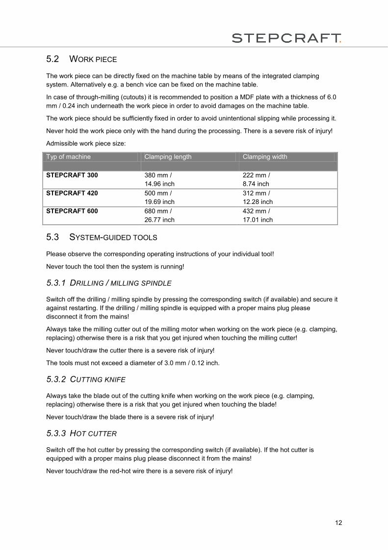
5.2 WORK PIECE
The work piece can be directly fixed on the machine table by means of the integrated clamping
system. Alternatively e.g. a bench vice can be fixed on the machine table.
In case of through-milling (cutouts) it is recommended to position a MDF plate with a thickness of 6.0
mm / 0.24 inch underneath the work piece in order to avoid damages on the machine table.
The work piece should be sufficiently fixed in order to avoid unintentional slipping while processing it.
Never hold the work piece only with the hand during the processing. There is a severe risk of injury!
Admissible work piece size:
Typ of machine Clamping length Clamping width
STEPCRAFT 300 380 mm /
14.96 inch
222 mm /
8.74 inch
STEPCRAFT 420 500 mm /
19.69 inch
312 mm /
12.28 inch
STEPCRAFT 600 680 mm /
26.77 inch
432 mm /
17.01 inch
5.3 SYSTEM-GUIDED TOOLS
Please observe the corresponding operating instructions of your individual tool!
Never touch the tool then the system is running!
5.3.1 DRILLING / MILLING SPINDLE
Switch off the drilling / milling spindle by pressing the corresponding switch (if available) and secure it
against restarting. If the drilling / milling spindle is equipped with a proper mains plug please
disconnect it from the mains!
Always take the milling cutter out of the milling motor when working on the work piece (e.g. clamping,
replacing) otherwise there is a risk that you get injured when touching the milling cutter!
Never touch/draw the cutter there is a severe risk of injury!
The tools must not exceed a diameter of 3.0 mm / 0.12 inch.
5.3.2 CUTTING KNIFE
Always take the blade out of the cutting knife when working on the work piece (e.g. clamping,
replacing) otherwise there is a risk that you get injured when touching the blade!
Never touch/draw the blade there is a severe risk of injury!
5.3.3 HOT CUTTER
Switch off the hot cutter by pressing the corresponding switch (if available). If the hot cutter is
equipped with a proper mains plug please disconnect it from the mains!
Never touch/draw the red-hot wire there is a severe risk of injury!
13
5.3.4 ENGRAVING POINT / PLOTTER PEN
Always take the engraving point out of the tool holder when working on the work piece (e.g. clamping,
replacing) otherwise there is a risk that you get injured when touching the engraving point!
Never touch/draw the engraving point there is a severe risk of injury!
5.3.5 3D-PRINTER HEAD
Switch off the 3D-printer head by pressing the corresponding switch (if available) and secure it against
loosing hot filament. If the 3D-printer head is equipped with a proper mains plug please disconnect it
from the mains!
Never touch/draw the hot printer head there is a severe risk of injury!
5.4 EMERGENCY-STOP SWITCH
The Emergency-Stop switch is located at the front side of the machine (refer to the schematics under
item 3.1 of these instructions).
If you press the switch the Emergency-Stop is released. The machine immediately stops (imperatively
refer to item 2.7 of these instructions).
Only press the Emergency-Stop switch in emergency situations!
If the switch is pressed it results in an immediate machine standstill and can result in step losses and
data losses.
A controlled stopping of the machine can only be performed by means of the control software.
In order to undo the Emergency-Stop status turn the Emergency-Stop switch to the right. Thus the
control is reactivated. The working process has to be restarted.
5.5 OPERATION OF THE SYSTEM / OPERATING ELEMENTS
The whole system is controlled and operated by means of a computer (PC).
Please completely read the manual of your control software before the first commissioning and make
sure that you understood everything.
For any further questions regarding the control software please contact the corresponding software
developer.
5.6 OPTIONAL ACCESSORY
Please find additional accessories in our Online-Shop at www.stepcraft-systems.com of your
STEPCRAFT such as:
System-guided tools, e.g. drilling / milling spindle, cutting knife, plotter pen, engraving point,
hot cutter, 3D-printer heads
Extension of the modular unit control e.g. the 4th axis module together with the CNC rotary
table
Grooved plate (aluminium) or systems for mounting and clamping e.g. bench vice, clamping
claws
Tools for drilling / milling and many more
14
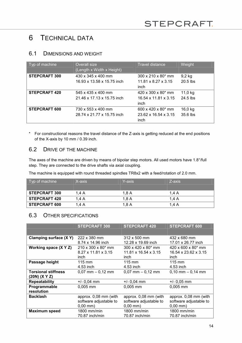
6 TECHNICAL DATA
6.1 DIMENSIONS AND WEIGHT
Typ of machine Overall size
(Length x Width x Height)
Travel distance Weight
STEPCRAFT 300 430 x 345 x 400 mm
16.93 x 13.58 x 15.75 inch
300 x 210 x 80* mm
11.81 x 8.27 x 3.15
inch
9,2 kg
20.5 lbs
STEPCRAFT 420 545 x 435 x 400 mm
21.46 x 17.13 x 15.75 inch
420 x 300 x 80* mm
16.54 x 11.81 x 3.15
inch
11,0 kg
24.5 lbs
STEPCRAFT 600 730 x 553 x 400 mm
28.74 x 21.77 x 15.75 inch
600 x 420 x 80* mm
23.62 x 16.54 x 3.15
inch
16,0 kg
35.6 lbs
* For constructional reasons the travel distance of the Z-axis is getting reduced at the end positions
of the X-axis by 10 mm / 0.39 inch.
6.2 DRIVE OF THE MACHINE
The axes of the machine are driven by means of bipolar step motors. All used motors have 1.8°/full
step. They are connected to the drive shafts via axial coupling.
The machine is equipped with round threaded spindles TR8x2 with a feed/rotation of 2.0 mm.
Typ of machine X-axis Y-axis Z-axis
STEPCRAFT 300 1,4 A 1,8 A 1,4 A
STEPCRAFT 420 1,4 A 1,8 A 1,4 A
STEPCRAFT 600 1,4 A 1,8 A 1,4 A
6.3 OTHER SPECIFICATIONS
STEPCRAFT 300 STEPCRAFT 420 STEPCRAFT 600
Clamping surface (X Y) 222 x 380 mm 8.74 x 14.96 inch
312 x 500 mm 12.28 x 19.69 inch
432 x 680 mm 17.01 x 26.77 inch
Working space (X Y Z) 210 x 300 x 80* mm 8.27 x 11.81 x 3.15 inch
300 x 420 x 80* mm 11.81 x 16.54 x 3.15 inch
420 x 600 x 80* mm 16.54 x 23.62 x 3.15 inch
Passage height 115 mm 4.53 inch
115 mm 4.53 inch
115 mm 4.53 inch
Torsional stiffness (20N) (X Y Z)
0,07 mm – 0,12 mm
0,07 mm – 0,12 mm 0,10 mm – 0,14 mm
Repeatability +/- 0,04 mm +/- 0,04 mm +/- 0,05 mm
Programmable resolution
0,005 mm 0,005 mm 0,005 mm
Backlash approx. 0,08 mm (with software adjustable to 0,00 mm)
approx. 0,08 mm (with software adjustable to 0,00 mm)
approx. 0,08 mm (with software adjustable to 0,00 mm)
Maximum speed 1800 mm/min 70.87 inch/min
1800 mm/min 70.87 inch/min
1800 mm/min 70.87 inch/min
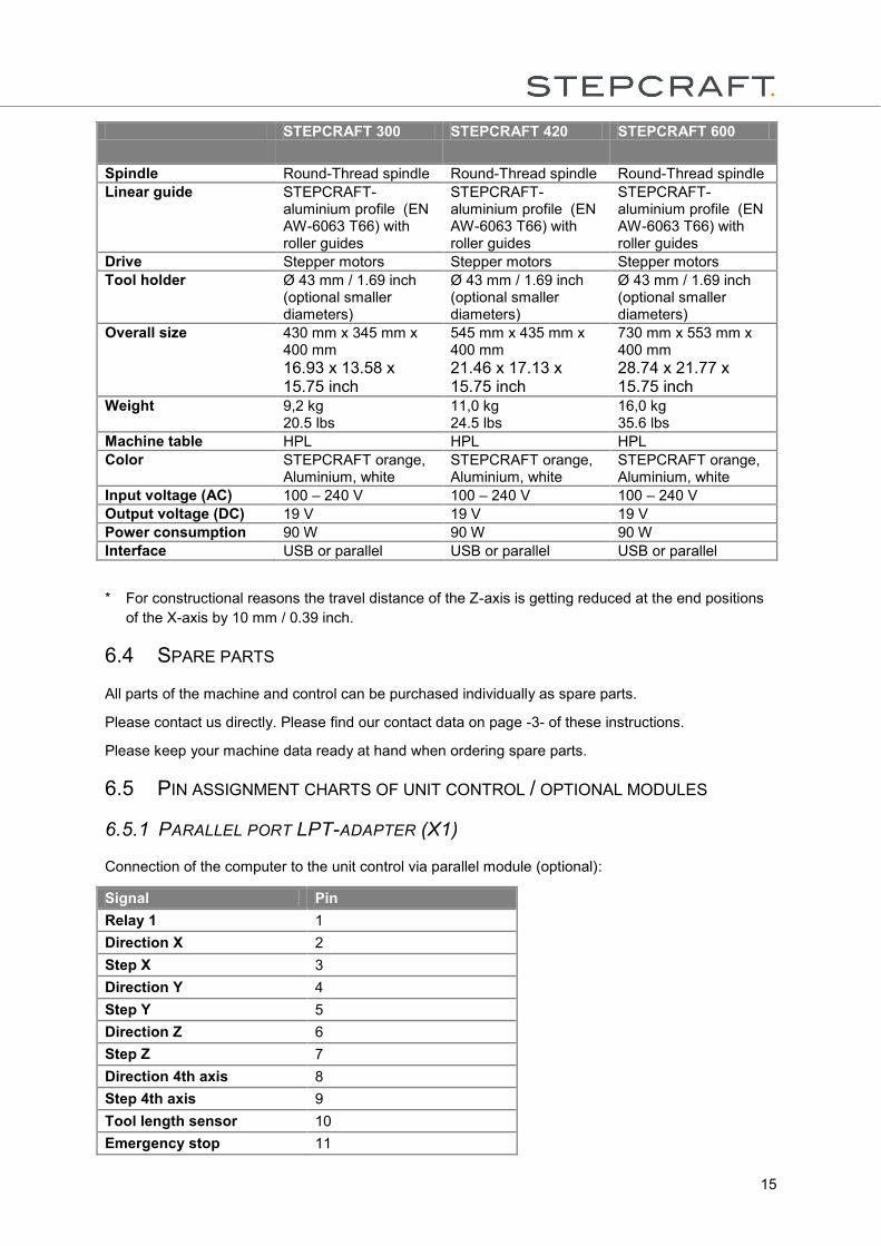
15
STEPCRAFT 300 STEPCRAFT 420 STEPCRAFT 600
Spindle Round-Thread spindle Round-Thread spindle Round-Thread spindle Linear guide STEPCRAFT-
aluminium profile (EN AW-6063 T66) with roller guides
STEPCRAFT-aluminium profile (EN AW-6063 T66) with roller guides
STEPCRAFT-aluminium profile (EN AW-6063 T66) with roller guides
Drive Stepper motors Stepper motors Stepper motors Tool holder Ø 43 mm / 1.69 inch
(optional smaller diameters)
Ø 43 mm / 1.69 inch (optional smaller diameters)
Ø 43 mm / 1.69 inch (optional smaller diameters)
Overall size 430 mm x 345 mm x 400 mm
16.93 x 13.58 x 15.75 inch
545 mm x 435 mm x 400 mm
21.46 x 17.13 x 15.75 inch
730 mm x 553 mm x 400 mm
28.74 x 21.77 x 15.75 inch
Weight 9,2 kg 20.5 lbs
11,0 kg 24.5 lbs
16,0 kg 35.6 lbs
Machine table HPL HPL HPL
Color STEPCRAFT orange, Aluminium, white
STEPCRAFT orange, Aluminium, white
STEPCRAFT orange, Aluminium, white
Input voltage (AC) 100 – 240 V 100 – 240 V 100 – 240 V
Output voltage (DC) 19 V 19 V 19 V
Power consumption 90 W 90 W 90 W
Interface USB or parallel USB or parallel USB or parallel
* For constructional reasons the travel distance of the Z-axis is getting reduced at the end positions
of the X-axis by 10 mm / 0.39 inch.
6.4 SPARE PARTS
All parts of the machine and control can be purchased individually as spare parts.
Please contact us directly. Please find our contact data on page -3- of these instructions.
Please keep your machine data ready at hand when ordering spare parts.
6.5 PIN ASSIGNMENT CHARTS OF UNIT CONTROL / OPTIONAL MODULES
6.5.1 PARALLEL PORT LPT-ADAPTER (X1)
Connection of the computer to the unit control via parallel module (optional):
Signal Pin
Relay 1 1
Direction X 2
Step X 3
Direction Y 4
Step Y 5
Direction Z 6
Step Z 7
Direction 4th axis 8
Step 4th axis 9
Tool length sensor 10
Emergency stop 11
16
Signal Pin
Reference switch X/Y/Z 12
Reference switch 4th axis 13
Relay 2 14
n.a. (In) 15
Relay 3 16
n.a. (out) 17
GND 18-25
PE shed
5V/VCC
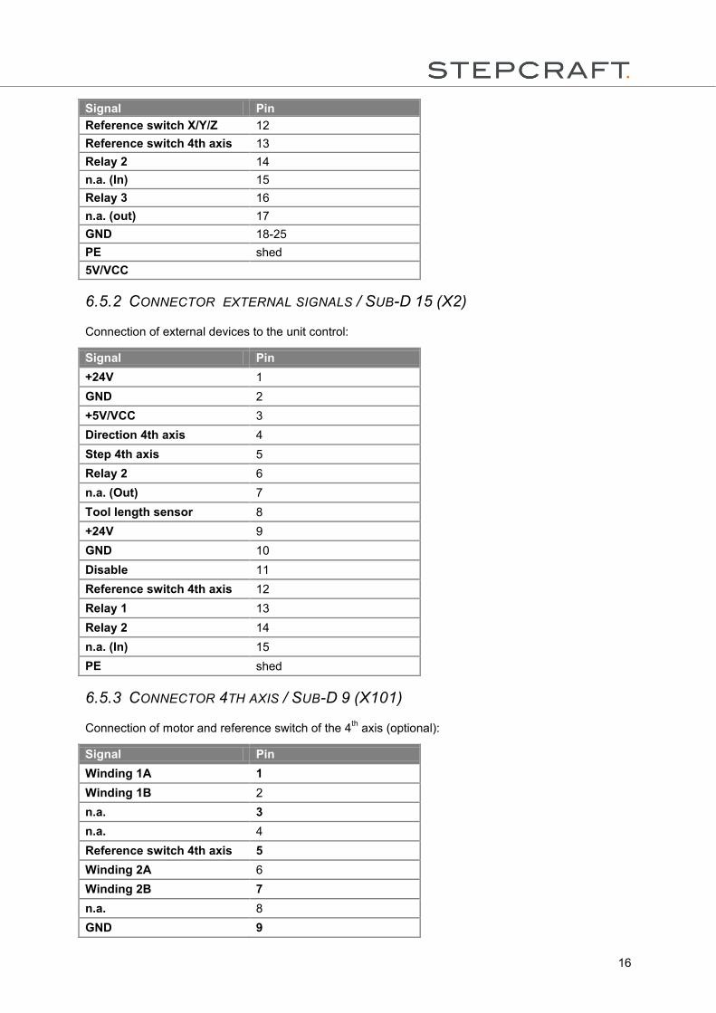
6.5.2 CONNECTOR EXTERNAL SIGNALS / SUB-D 15 (X2)
Connection of external devices to the unit control:
Signal Pin
+24V 1
GND 2
+5V/VCC 3
Direction 4th axis 4
Step 4th axis 5
Relay 2 6
n.a. (Out) 7
Tool length sensor 8
+24V 9
GND 10
Disable 11
Reference switch 4th axis 12
Relay 1 13
Relay 2 14
n.a. (In) 15
PE shed
6.5.3 CONNECTOR 4TH AXIS / SUB-D 9 (X101)
Connection of motor and reference switch of the 4th axis (optional):
Signal Pin
Winding 1A 1
Winding 1B 2
n.a. 3
n.a. 4
Reference switch 4th axis 5
Winding 2A 6
Winding 2B 7
n.a. 8
GND 9
17
Signal Pin
PE shed
7 TRANSPORTATION / STORAGE
7.1 TRANSPORTATION
Please observe that the machine is very heavy and bulky when transporting it.
If necessary transport the machine with the help of a second person.
Please only use suitable transportation vehicles and carriers for transportation.
Never lift heavy loads above people!
7.2 PACKAGING
When you do not want to reuse the packaging material of the machine and of its components please
separate it according to the disposal conditions on site and take it to a collection center for recycling or
dispose of it.
7.3 STORAGE
If the machine or its components is not used for a longer time please note the following for the storage:
Store the machine and the components only in closed rooms
Protect it against humidity, wetness, cold, heat and direct sun radiation
Store it dust-free, cover it, if required
The storage place must not be subject to vibrations
8 MAINTENANCE
8.1 SAFETY
Before performing maintenance works on the machine switch it off and secure it against unintended
restarting by disconnecting the mains switch of the controller!
If you use a milling spindle with its own mains plug disconnect it also!
All maintenance works must only be performed by a technically experienced person.
In case of improper handling of the machine there is a high risk of injury!
8.2 MAINTENANCE WORKS
Always thoroughly handle your STEPCRAFT in order to enjoy working with it for a long time.
Regular maintenance crucially influences the service life of your machine.
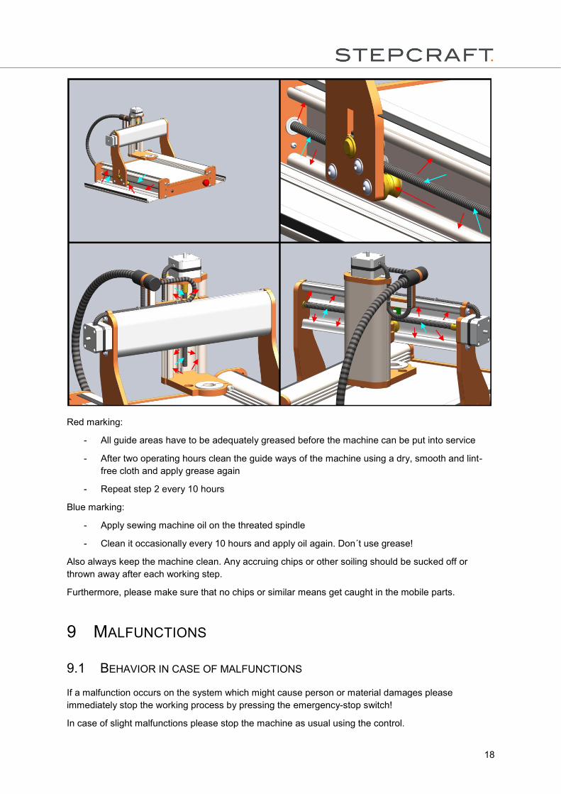
Therefore please perform the following maintenance:
18
Red marking:
- All guide areas have to be adequately greased before the machine can be put into service
- After two operating hours clean the guide ways of the machine using a dry, smooth and lint-
free cloth and apply grease again
- Repeat step 2 every 10 hours
Blue marking:
- Apply sewing machine oil on the threated spindle
- Clean it occasionally every 10 hours and apply oil again. Don´t use grease!
Also always keep the machine clean. Any accruing chips or other soiling should be sucked off or
thrown away after each working step.
Furthermore, please make sure that no chips or similar means get caught in the mobile parts.
9 MALFUNCTIONS
9.1 BEHAVIOR IN CASE OF MALFUNCTIONS
If a malfunction occurs on the system which might cause person or material damages please
immediately stop the working process by pressing the emergency-stop switch!
In case of slight malfunctions please stop the machine as usual using the control.
19
If you are not able to remedy the malfunction yourself please contact us by indicating the malfunction
which occurred.
Please find our contact data on page -3- of these instructions.
10 ANNEX
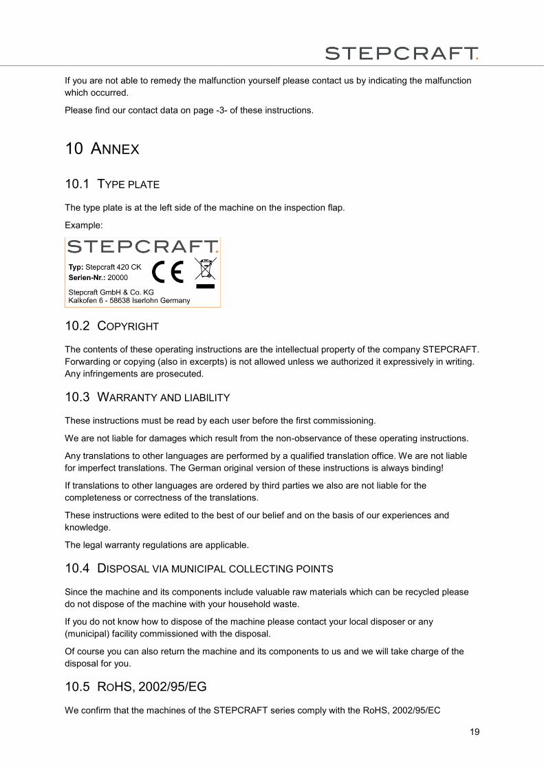
10.1 TYPE PLATE
The type plate is at the left side of the machine on the inspection flap.
Example:
10.2 COPYRIGHT
The contents of these operating instructions are the intellectual property of the company STEPCRAFT.
Forwarding or copying (also in excerpts) is not allowed unless we authorized it expressively in writing.
Any infringements are prosecuted.
10.3 WARRANTY AND LIABILITY
These instructions must be read by each user before the first commissioning.
We are not liable for damages which result from the non-observance of these operating instructions.
Any translations to other languages are performed by a qualified translation office. We are not liable
for imperfect translations. The German original version of these instructions is always binding!
If translations to other languages are ordered by third parties we also are not liable for the
completeness or correctness of the translations.
These instructions were edited to the best of our belief and on the basis of our experiences and
knowledge.
The legal warranty regulations are applicable.
10.4 DISPOSAL VIA MUNICIPAL COLLECTING POINTS
Since the machine and its components include valuable raw materials which can be recycled please
do not dispose of the machine with your household waste.
If you do not know how to dispose of the machine please contact your local disposer or any
(municipal) facility commissioned with the disposal.
Of course you can also return the machine and its components to us and we will take charge of the
disposal for you.
10.5 ROHS, 2002/95/EG
We confirm that the machines of the STEPCRAFT series comply with the RoHS, 2002/95/EC
20
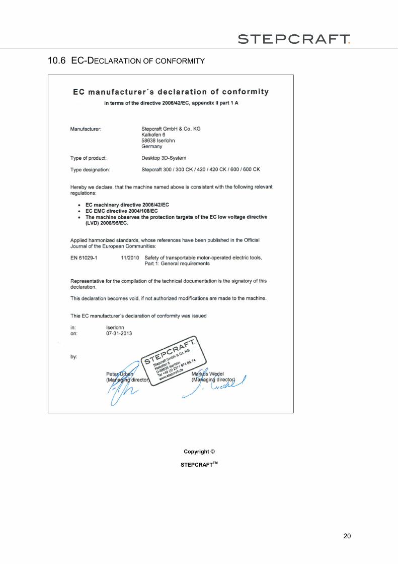
10.6 EC-DECLARATION OF CONFORMITY
Copyright ©
STEPCRAFTTM