Embed Size (px)
Citation preview

i
DESKPOWER P300 Series User’s Manual(Model: P301 / P310)
Fujitsu endeavours to ensure that the information in this document is correct, but accepts no liabilityfor any error or omission in the same. Any procedures described in this document for operating Fujitsuproducts should be read and understood by the operator before such products are used. To ensurethat Fujitsu products function without risk to safety and health, such procedures should be strictlyobserved by the operator. The development of Fujitsu products and services is continuous andpublished information may not be up to date. Any particular issue of a product may contain facilitiesnot described herein. It is important to check the current position with Fujitsu. Specifications andstatements as to performance in this document are Fujitsu estimates intended for general guidance.They may require adjustment in particular circumstances and should therefore not be taken as formaloffers or commitments.
DESKPOWER is a trademark of Fujitsu Limited. The following are registered trademarks of MicrosoftCorporation: MS, MS-DOS, Windows ® NT, Windows ® 98, Windows Millennium, Window ® 2000 andWindows XP.Intel and Pentium are registered trademarks of Intel Corporation in the U.S.Celeron is a registered trademark of Intel Corporation in the U.S.Other product names are trademarks or registered trademarks of respective companies.Other products are copyrighted by individual companies.
All other trademarks referenced are trademarks or registered trademarks of their respective owners,whose protected rights are acknowledged.
Copyright © Fujitsu PC Asia Pacific
All rights, including rights of translation, reproduction by printing, copying or similar methods, in partor in whole, are reserved.
Offenders will be liable for damages.
All rights, including rights created by patent grant or registration of a utility model or design, are reserved.
Delivery subject to availability. Right of teachnical modification reserved.
DECLARATION OF CONFORMITYaccording to FCC Part 15 Class B
This device complies with Part 15 Class B of the FCC Rules. Operations are subject to the followingtwo conditions:(1) This device may not be allowed to cause harmful interference, (2) This device must accept anyinterference received, including interference that may cause undesired operation.
Wesbite: www.pc-ap.fujitsu.com
CHAPTER 0 Wash2 (INTRO) 4/9/03, 4:30 PM1

ii
Important safety instructions
1. Read these instructions carefully. Save these instructions for future reference.
2. Follow all warnings and instructions marked on the product.
3. Unplug this product from the wall outlet before cleaning. Do not use liquid cleaners or aerosolcleaners. Use a damp cloth for cleaning.
4. Do not use this product near water.
5. Do not place this product on an unstable cart, stand, or table. The product may fall, causing seriousdamage to the product.
6. Slots and openings in the cabinet and the back or bottom are provided for ventilation; to ensurereliable operation of the product and to protect it from overheating, these openings must not beblocked or covered. The openings should never be blocked by placing the product on a bed, sofa,rug, or other similar surface. This product should never be placed near or over a radiator or heatregister, or in a built-in installation unless proper ventilation is provided.
7. This product should be operated from the type of power indicated on the marking label. If you arenot sure of the type of power available, consult your dealer or local power company.
8. This product is equipped with a 3-wire grounding-type plug, a plug having a third (grounding) pin.This will only plug into a grounding-type power outlet. This is a safety feature. If you are unable toinsert the plug into the outlet, contact your electrician to replace your obsolete outlet. Do not defeatthe purpose of the grounding-type plug.
9. Do not allow anything to rest on the power cord. Do not locate this product where persons willwalk on the cord.
10. If an extension cord is used with this product, make sure that the total ampere rating of theequipment plugged into the extension cord does not exceed the extension cord ampere rating.Also, make sure that the total rating of all products plugged into the wall outlet does not exceed15 amperes.
11. Never push objects of any kind into this product through cabinet slots as they may touch dangerousvoltage points that could result in a fire or electric shock. Never spill liquid of any kind on the product.
12. Do not attempt to service this product yourself, as opening or removing covers may expose youto dangerous voltage points or other risks. Refer all servicing to qualified service personnel.
CHAPTER 0 Wash2 (INTRO) 12/8/03, 12:23 PM2
iii
13. Unplug this product from the wall outlet and refer servicing to qualified service personnel underthe following conditions:a. When the power cord or plug is damaged or frayed.b. If liquid has been spilled into the product.c. If the product has been exposed to rain or water.d. If the product does not operate normally when the operating instructions are followed. Adjust
only those controls that are covered by the operating instructions since improper adjustmentof other controls may result in damage and will often require extensive work by a qualifiedtechnician to restore the product to normal condition.
e. If the product has been dropped or the cabinet has been damaged.f. If the product exhibits a distinct change in performance, indicating a need for service.
14. CAUTION. When replacing the battery, be sure to install it with the polarities in the correctposition. There is a danger of explosion if the battery is replaced with an incorrect type oris mistreated. Do not recharge, disassemble or dispose of in fire. Replace only with thesame or equivalent type recommeded by the manufacturer. Dispose of the used batteryaccording to the manufacturer’s instructions.
15. Use only the proper type of power supply cord set (provided in your accessories box) for this unit.It should be a detachable type: UL listed/CSA certified, BS1363,ASTA,SS145 certified, rated 10A250V minimum, VDE approved or its equivalent. Maximum length is 15 feet (4.6 meters).
16. NOTE:Please take extra precaution when connecting the LAN cable; do not connect the LAN cableto the peripheral device’s connector, that might have excessive voltage.
CHAPTER 0 Wash2 (INTRO) 12/8/03, 12:23 PM3
iv
Before reading this manual
This section describes safety precautions and convention used in this manual. Be sure to read this.
For Safe Operation
This manual contains important information for using the DESKPOWER personal computer.Read this manual thoroughly before using your PC. In particular, “Safety Precautions” in this manualmust be read and understood.This manual including “Safety Precautions” must be readily available at all times.
This equipment is compliant with the PC industry standard (PC-11-1988) of the Japan Electronicsand Information Technology Industries Association.
Note
This product is a Class B Information Technology Equipment and conforms to the standard set bythe Voluntary Control Council for Interference by Technology Equipment (VCCI).This product isdesigned to be used in a domestic environment, however, it may cause radio interference whenused in the vicinity of a radio or television receiver.Make sure that you read the manual when using this product.
Fujitsu, as a member of the International Energy Star Program, recognizes thatthis equipment is compliant with the standard of the International Energy StarProgram.The International Energy Star Program is a worldwide program for promotingenergy saving for computers and other office equipment. The program aims atpromoting the development and use of products equipped with the functions that can effectivelyreduce energy consumption and uses a voluntary system that allows enterprises to join at theirown discretion. The target products are office equipment including computers, displays, printers,facsimiles, and copying machines. The standards for individual types of equipment and the mark( ) prepared by the Program are used commonly among member countries.
Caution
This equipment is class B information technology equipment based on the standard of the VoluntaryControl Council for Interference by Information Technology Equipment (VCCI). Although theequipment is intended for use in residential environments, it may create interference if placed nearradio or television.Handle the equipment in accordance with the manual.
CHAPTER 0 Wash2 (INTRO) 12/8/03, 12:23 PM4
v
Using this Product for High-Safety Applications
This product is for office, personal, home, ordinary industry and other general use. It is not designedand manufactured for use in high-safety applications.Do not use this product for such applications without taking measures to satisfy the high-safetyrequirements.High-safety applications require extremely high level of safety, and involve serious hazards to lifeand health if the required safety is not assured. High-safety applications include the following.● Nuclear reaction control in nuclear facilities, automatic aviation control, air traffic control, mass-
transportation control, life-supporting medical equipment, and missile launch control.
Some parts (including the CRT display, LCD, or hard disk drive) used on this product have a limitedlife. When used continuously for a prolonged period, these parts will need earlier replacement.
Backing Up the Data
The customer is responsible for maintaining the integrity of data (including the basic and applicationsoftware) stored or installed on the product. We do not warrant the integrity of data stored or installedon the personal computer the customer sent for repair. Take appropriate measures such as makinga backup.We assume no responsibility for loss of data and any direct or incidental damage due to any causeother than those specified in the warranty.
This computer is designed for use within the country. If you are using it abroad, please do so onyour own responsibility.
This equipment may be adversely affected by the momentary drop of the supplied voltage due tolightning. Use of an AC uninterruptible power supply is recommended for measures against themomentary drop of the supplied voltage.(This message is based on the Japan Electronics and Information Technology IndustriesAssociation’s guidelines for measures against momentary voltage drop in PCs.)
Since this equipment contains special materials controlled by the Foreign Exchange and ForeignTrade Control Law. Authorization under the law may be required to export this equipment.
CHAPTER 0 Wash2 (INTRO) 12/8/03, 12:23 PM5

vi
Microsoft Service Pack
Microsoft Corp. offers Service Pack to provide the users of Microsoft® Windows® with more stablesystem operation (http://www.microsoft.com/).The latest version of the Service Pack helps you configure the most stable system using Microsoft®
Windows® provided at that time by Microsoft Corp.We recommend you to use the latest version.In some environments, however, the Service Pack may cause unexpected failure. ReadReadme.txt for the Service Pack before use.Again, we recommend you to make a system backup in case of failed installation.
Components of this product (motherboard, CD-ROM, hard disk, and floppy disk drive) containtraces of heavy metals (lead and chrome) and chemical (antimony).
CHAPTER 0 Wash2 (INTRO) 12/8/03, 12:23 PM6
vii
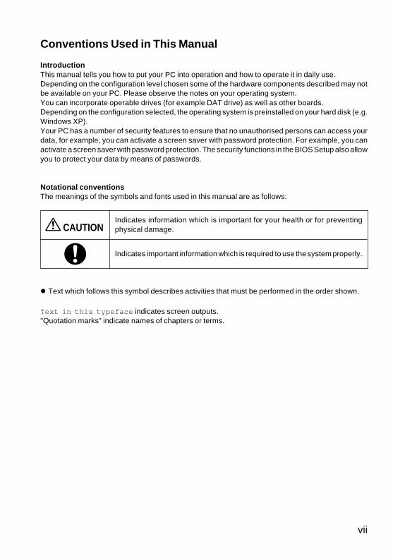
Conventions Used in This Manual
IntroductionThis manual tells you how to put your PC into operation and how to operate it in daily use.Depending on the configuration level chosen some of the hardware components described may notbe available on your PC. Please observe the notes on your operating system.You can incorporate operable drives (for example DAT drive) as well as other boards.Depending on the configuration selected, the operating system is preinstalled on your hard disk (e.g.Windows XP).Your PC has a number of security features to ensure that no unauthorised persons can access yourdata, for example, you can activate a screen saver with password protection. For example, you canactivate a screen saver with password protection. The security functions in the BIOS Setup also allowyou to protect your data by means of passwords.
Notational conventionsThe meanings of the symbols and fonts used in this manual are as follows:
Indicates information which is important for your health or for preventingphysical damage.
Indicates important information which is required to use the system properly.
� Text which follows this symbol describes activities that must be performed in the order shown.
Text in this typeface indicates screen outputs."Quotation marks" indicate names of chapters or terms.
CAUTION
CHAPTER 0 Wash2 (INTRO) 12/8/03, 12:23 PM7
viii
Important Notes
In this chapter you will find information regarding safety which is essential to take note of when workingwith your PC. The manufacturer's notes contain helpful information on your PC.
� Safety
CAUTION
During installation and before operating the device, please observe the instructions onenvironmental conditions in the chapter entitled "Technical data" as well as the instructions in thechapter "Preparing for Use".Please check whether the device is correctly set for the local power supply (see "Preparing forUse" chapter).The main switch and the ON/OFF switch do not disconnect the system unit from the mains voltage.To completely disconnect the mains voltage, remove the power plug from the grounded mainsoutlet.Replace the lithium battery on the system board in accordance with the instructions in the "Systemexpansions - Replacing lithium battery" chapter.Caution: components in the system can get very hot.
� Manufacturer’s notesKeep this operating manual together with your device. If you pass on the device to third parties,you should include this manual.
� Energy savingWhen the PC is delivered, some energy-saving functions are already set� If you are not using your PC, switch it off.� In the BIOS Setup you may set further energy-saving functions for the PC.� Depending on the operating system, you can set additional power-management features.
Energy saving under Windows 2000/XPThe Screen Saver tab allows you to set energy-saving functions for your screen. Select thefollowing item in the menu: Start → Settings → Control Panel → Display → Display Properties →Screen Saver → Energy saving features of monitor.With the default setting Control Panel → Power Options → Advanced additional powermanagement features of Windows 2000/XP are available.
CHAPTER 0 Wash2 (INTRO) 12/8/03, 12:23 PM8
ix
� FCC Class B Compliance StatementThe following statement applies to the products covered in this manual, unless otherwise specifiedherein. The statement for other products will appear in the accompanying documentation.
NOTE:This equipment has been tested and found to comply with the limits for a "Class B" digital device,pursuant to Part 15 of the FCC rules and meets all requirements of the Canadian Interference-Causing Equipment Regulations. These limits are designed to provide reasonable protectionagainst harmful interference in a residential installation. This equipment generates, uses andcan radiate radio frequency energy and, if not installed and used in strict accordance with theinstructions, may cause harmful interference to radio communications. However, there is noguarantee that interference will not occur in a particular installation. If this equipment does causeharmful interference to radio or television reception, which can be determined by turning theequipment off and on, the user is encouraged to try to correct the interference by one or more ofthe following measures:
� Reorient or relocate the receiving antenna.� Increase the separation between equipment and the receiver.� Connect the equipment into an outlet on a circuit different from that to which the receiver is
connected.� Consult the dealer or an experienced radio/TV technician for help.
Fujitsu is not responsible for any radio or television interference caused by unauthorisedmodifications of this equipment or the substitution or attachment of connecting cables andequipment other than those specified by Fujitsu. The correction of interference caused by suchunauthorised modification, substitution or attachment will be the responsibility of the user.
The use of shielded I/O cables is required when connecting this equipment to any and all optionalperipheral or host devices. Failure to do so may violate FCC rules.
CHAPTER 0 Wash2 (INTRO) 12/8/03, 12:23 PM9
x
� Transporting the PC
CAUTION
Transport all parts separately in their original packaging or in a packaging which protects themfrom knocks and jolts, to the new site. Do not unpack them until all transportation manoeuvresare completed.Never drop the monitor!
� Cleaning the PC
CAUTION
Turn off all power and equipment switches and remove the power plug from the mains supply.Do not clean any interior parts yourself, leave this job to a service technician.Do not use any cleaning agents that contain abrasives or may corrode plastic.Ensure that no liquid enters the system.Ensure that the ventilation areas of the system unit and the monitor are free.
Cleaning the system unit and the monitorWipe the system unit and monitor casing with a dry cloth. If particularly dirty, use a cloth that hasbeen moistened in mild domestic detergent and then carefully wrung out.
Cleaning the keyboard and the mouseUse disinfectant wipes to clean the keyboard and the mouse.The mouse mechanism and the mouse ball can be cleaned by removing the retaining ring on theunderside of the mouse.
Additional information can be found in the documentation for your keyboard and mouse.
CHAPTER 0 Wash2 (INTRO) 12/8/03, 12:23 PM10
xi
� Disposal and recycling
This device has been manufactured to the highest possible degree from materials which can berecycled or disposed of in a manner that is not environmentally damaging. The device may be takenback after use to be recycled, provided that it is returned in a condition that is the result of normal use.Any components not reclaimed will be disposed of in an environmentally acceptable manner.
Do not throw lithium batteries into the household waste. They must be disposed of in accordancewith local regulations concerning special waste.
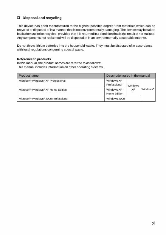
Reference to productsIn this manual, the product names are referred to as follows:This manual includes information on other operating systems.
Product name Description used in the manual
Microsoft® Windows® XP Professional
Microsoft® Windows® XP Home Edition
Microsoft® Windows® 2000 Professional
Windows*Windows
XP
Windows XPProfessional
Windows XPHome Edition
Windows 2000
CHAPTER 0 Wash2 (INTRO) 12/8/03, 12:23 PM11
xii
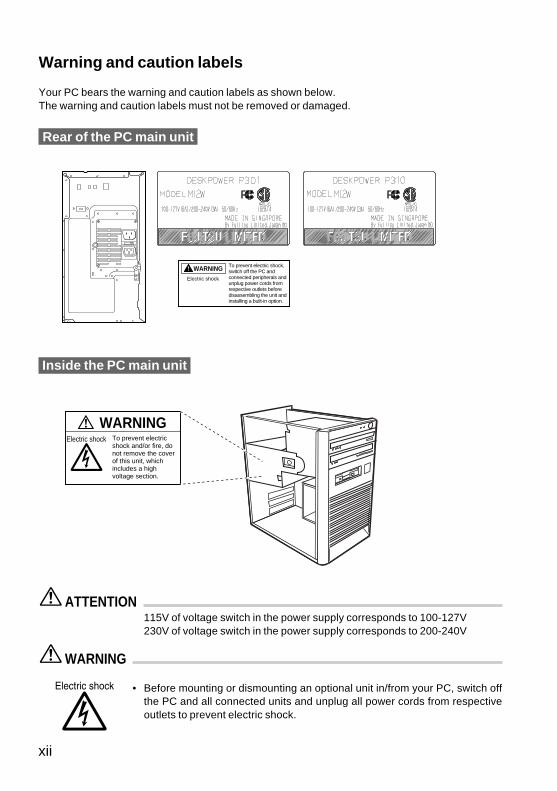
Warning and caution labels
Your PC bears the warning and caution labels as shown below.The warning and caution labels must not be removed or damaged.
Rear of the PC main unit
ATTENTION115V of voltage switch in the power supply corresponds to 100-127V230V of voltage switch in the power supply corresponds to 200-240V
WARNING
• Before mounting or dismounting an optional unit in/from your PC, switch offthe PC and all connected units and unplug all power cords from respectiveoutlets to prevent electric shock.
Electric shock
WARNING To prevent electric shock, switch off the PC and connected peripherals and unplug power cords from respective outlets before disassembling the unit and installing a built-in option.
Electric shock
WARNINGTo prevent electric shock and/or fire, do not remove the cover of this unit, which includes a high voltage section.
Inside the PC main unit
CHAPTER 0 Wash2 (INTRO) 4/9/03, 4:30 PM12
xiii
Before Reading This ManualThis section contains cautions for safe operation, representations and symbols used in this manual.Be sure to read this first!
Chapter 1 Preparing for Use
This chapter provides the names and functions of individual parts.
Chapter 2 Operation
This section describes the location of installation and installation of the computer.
Chapter 3 Troubleshooting and Tips
This chapter provides the basic information on the PC and operation.
Chapter 4 System Expansion
This chapter provides basic information on how to handle the peripherals installed(or can be installed) on the PC.
Chapter 5 Technical Data
This chapter describes the specifications of this PC.
Organization of This Manual
CHAPTER 0 Wash2 (INTRO) 12/8/03, 12:23 PM13
xiv
Contents
CHAPTER 1 Preparing for Use
1 Preparing for Use ..............................................................................2Unpacking and Checking the Delivery ............................................................. 2Steps for Initial Setup ....................................................................................... 2Setting Up the PC ............................................................................................ 3Connect the Monitor, Mouse and Keyboard ..................................................... 3Connecting the PC to the Mains Voltage .......................................................... 5Initial Switch-on: Software will be Installed ....................................................... 6Connecting External Devices ........................................................................... 8
CHAPTER 2 Operation
1 Operation .........................................................................................12Switching On the PC ...................................................................................... 12Switching Off the PC ...................................................................................... 13Indicators on the PC ....................................................................................... 14
2 Keyboard .........................................................................................153 Floppy Disks ...................................................................................17
Working with Floppy Disks ............................................................................. 17Settings in BIOS Setup .................................................................................. 18Property and Data Protection ......................................................................... 18Access Protection Under Windows ................................................................ 18BIOS Setup Security Functions ...................................................................... 19
CHAPTER 3 Troubleshooting and Tips
1 Troubleshooting and Tips ..............................................................22Installing New Software .................................................................................. 22Power-on Indicator Remains Unlit After You Have Switched on Your Device . 22No Mouse Pointer Displayed on the Screen ................................................... 24The Floppy Disk Cannot be Read or Written .................................................. 24Time and/or Date is Not Correct .................................................................... 25Tips ................................................................................................................ 25
CHAPTER 0 Wash2 (INTRO) 12/8/03, 12:23 PM14
xv
CHAPTER 4 System Expansion
1 System Expansions ........................................................................28Information about boards ............................................................................... 28Opening the casing ........................................................................................ 29Closing the casing .......................................................................................... 29Installing and Removing a Board ................................................................... 30Low-Profiles boards ....................................................................................... 34Installing an Additional Serial Port ................................................................. 34Installing and Removing the Hard Disk Drives ............................................... 35Replacing Lithium Battery .............................................................................. 37
CHAPTER 5 Technical Data
1 Technical Data .................................................................................39Electrical Data ................................................................................................ 40
CHAPTER 0 Wash2 (INTRO) 12/8/03, 12:23 PM15

xvi
CHAPTER 0 Wash2 (INTRO) 12/8/03, 12:23 PM16

CHAPTER 1Preparing for Use
CHAPTER 1 Washingtons (01-10) 12/8/03, 11:39 AM1
2
1 Preparing for Use
CAUTION
Please take note of the safety information in the "Important notes" chapter.
■ Unpacking and Checking the DeliveryIt is recommended not to throw away the original packaging material! It may be required forreshipment at some later date.● Unpack all the individual parts.● Check the delivery for damage incurred during transportation.● Check whether the delivery agrees with the details in the delivery note.Should you discover that the delivery does not correspond to the delivery note, notify your localsales outlet immediately.
■ Steps for Initial SetupFirst-time setup includes the connection of the monitor, mouse and keyboard to the system unitand the setup of the supplied software.
● External devicesIf you have received other devices in addition to your PC (e.g. a printer or a modem), donot connect these until after the initial installation. The following sections contain adescription of how to connect these external devices: "Connecting external devices tothe serial port" and "Connecting external devices to the parallel port".
● Drives and boardsIf you have received drives or boards with your PC, please do not install them until afterfirst-time setup. How to install drives and boards is described in the chapter "Systemexpansions".
Perform the following steps in the prescribed order:
1. Decide where you are going to use the PC, and then set it up.
2. Connect the monitor, mouse and keyboard to the PC.
3. Check the rated voltage of the PC and connect it to the mains voltage.
4. Switch the PC on and follow the instructions on the screen.
CHAPTER 1 Washingtons (01-10) 12/8/03, 11:39 AM2
3
■ Setting Up the PC
CAUTION
When installing your PC, give consideration to the recommendations and safety notes.Set up the PC only in its correct orientation. The points to observe are illustrated on the followingpages.We recommend that you place your equipment on a surface with good anti-slip qualities. In viewof the multitude of different finishes and varnishes used on furniture, it is possible that the rubberfeet of the devices will mark the surface they stand on.Do not expose the PC to extreme environmental conditions (see chapter "Technical data") andprotect it from dust, humidity and heat.Provide at least 200 mm of clearance on the left, in front of and behind the ventilator area of thesystem unit to ensure adequate ventilation. Do not cover the ventilation areas of the monitor andthe system unit.Do not place several system units one above the other.
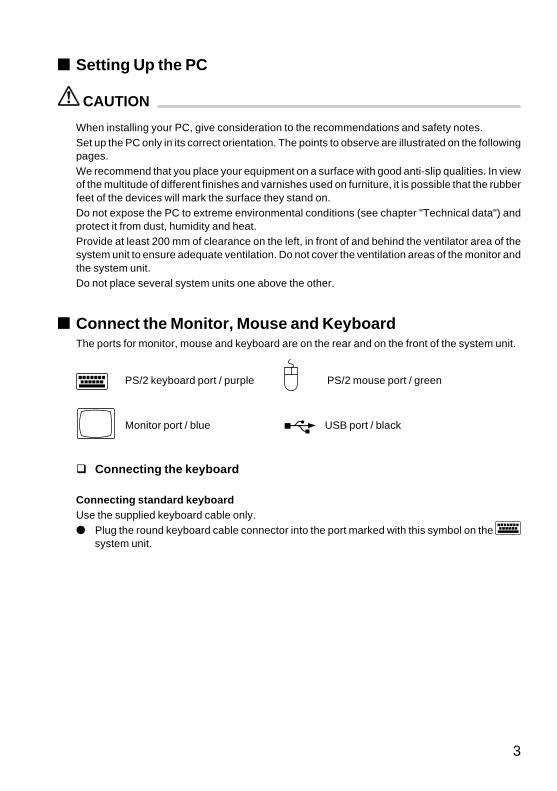
■ Connect the Monitor, Mouse and KeyboardThe ports for monitor, mouse and keyboard are on the rear and on the front of the system unit.
PS/2 keyboard port / purple PS/2 mouse port / green
Monitor port / blue USB port / black
� Connecting the keyboard
Connecting standard keyboardUse the supplied keyboard cable only.● Plug the round keyboard cable connector into the port marked with this symbol on the
system unit.
CHAPTER 1 Washingtons (01-10) 12/8/03, 11:39 AM3
4
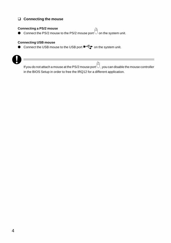
� Connecting the mouse
Connecting a PS/2 mouse● Connect the PS/2 mouse to the PS/2 mouse port on the system unit.
Connecting USB mouse● Connect the USB mouse to the USB port on the system unit.
If you do not attach a mouse at the PS/2 mouse port , you can disable the mouse controller
in the BIOS Setup in order to free the IRQ12 for a different application.
CHAPTER 1 Washingtons (01-10) 12/8/03, 11:39 AM4
5
■ Connecting the PC to the Mains Voltage
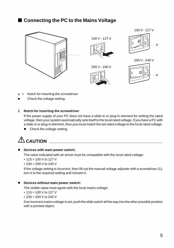
1 Notch for inserting the screwdriver
If the power supply of your PC does not have a slide-in or plug-in element for setting the ratedvoltage, then your system automatically sets itself to the local rated voltage. If you have a PC witha slide-in or plug-in element, then you must match the set rated voltage to the local rated voltage.� Check the voltage setting.
CAUTION
� Devices with main power switch:The value indicated with an arrow must be compatible with the local rated voltage:• 115 = 100 V to 127 V• 230 = 200 V to 240 V
If the voltage setting is incorrect, then lift out the manual voltage adjuster with a screwdriver (1),turn it to the required setting and reinsert it.
� Devices without main power switch:
The visible value must agree with the local mains voltage:• 115 = 100 V to 127 V• 230 = 200 V to 240 V
If an incorrect mains voltage is set, push the slide switch all the way into the other possible positionwith a pointed object.
200 V - 240 V
200 V - 240 V
100 V - 127 V
100 V - 127 V
a
a
a = Notch for inserting the screwdriver3 Check the voltage setting.
CHAPTER 1 Washingtons (01-10) 12/8/03, 11:39 AM5
6
2
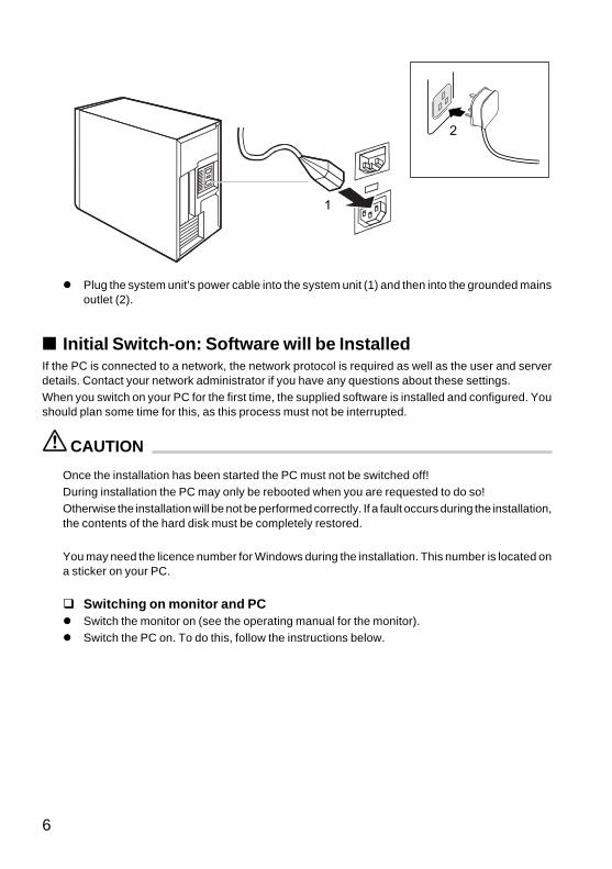
1
� Plug the system unit's power cable into the system unit (1) and then into the grounded mainsoutlet (2).
■ Initial Switch-on: Software will be InstalledIf the PC is connected to a network, the network protocol is required as well as the user and serverdetails. Contact your network administrator if you have any questions about these settings.When you switch on your PC for the first time, the supplied software is installed and configured. Youshould plan some time for this, as this process must not be interrupted.
CAUTION
Once the installation has been started the PC must not be switched off!During installation the PC may only be rebooted when you are requested to do so!Otherwise the installation will be not be performed correctly. If a fault occurs during the installation,the contents of the hard disk must be completely restored.
You may need the licence number for Windows during the installation. This number is located ona sticker on your PC.
� Switching on monitor and PC� Switch the monitor on (see the operating manual for the monitor).� Switch the PC on. To do this, follow the instructions below.
CHAPTER 1 Washingtons (01-10) 12/8/03, 11:39 AM6
7
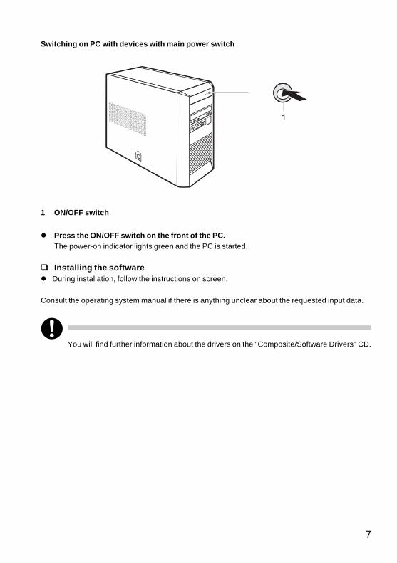
Switching on PC with devices with main power switch
1
1 ON/OFF switch
� Press the ON/OFF switch on the front of the PC.The power-on indicator lights green and the PC is started.
� Installing the software� During installation, follow the instructions on screen.
Consult the operating system manual if there is anything unclear about the requested input data.
You will find further information about the drivers on the "Composite/Software Drivers" CD.
CHAPTER 1 Washingtons (01-10) 12/8/03, 11:39 AM7
8
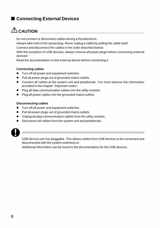
■ Connecting External Devices
CAUTION
Do not connect or disconnect cables during a thunderstorm.Always take hold of the actual plug. Never unplug a cable by pulling the cable itself.Connect and disconnect the cables in the order described below.With the exception of USB devices, always remove all power plugs before connecting externaldevices!Read the documentation on the external device before connecting it.
Connecting cables� Turn off all power and equipment switches.� Pull all power plugs out of grounded mains outlets.� Connect all cables at the system unit and peripherals. You must observe the information
provided in the chapter "Important notes".� Plug all data communication cables into the utility sockets.� Plug all power cables into the grounded mains outlets.
Disconnecting cables� Turn off all power and equipment switches.� Pull all power plugs out of grounded mains outlets.� Unplug all data communication cables from the utility sockets.� Disconnect all cables from the system unit and peripherals.
USB devices are hot-pluggable. This allows cables from USB devices to be connected anddisconnected with the system switched on.Additional information can be found in the documentation for the USB devices.
CHAPTER 1 Washingtons (01-10) 12/8/03, 11:39 AM8
9
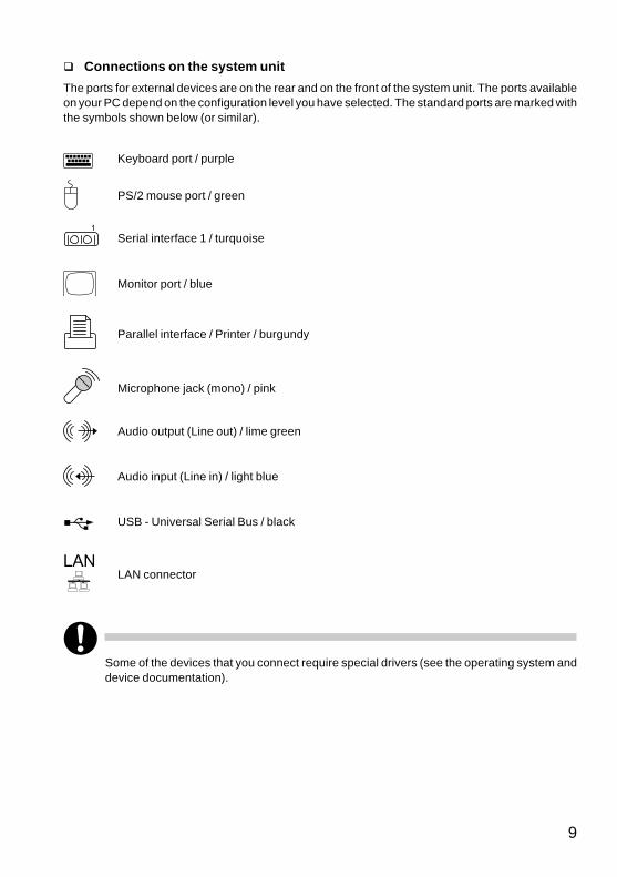
� Connections on the system unit
The ports for external devices are on the rear and on the front of the system unit. The ports availableon your PC depend on the configuration level you have selected. The standard ports are marked withthe symbols shown below (or similar).
Keyboard port / purple
PS/2 mouse port / green
1
Serial interface 1 / turquoise
Monitor port / blue
Parallel interface / Printer / burgundy
Microphone jack (mono) / pink
Audio output (Line out) / lime green
Audio input (Line in) / light blue
USB - Universal Serial Bus / black
LANLAN connector
Some of the devices that you connect require special drivers (see the operating system anddevice documentation).
CHAPTER 1 Washingtons (01-10) 12/8/03, 11:39 AM9
10
� Connecting external devices to the serial port
External devices can be connected to the serial port (e.g. a modem).
� Connect the data cable to the external device.
� Connect the data cable to the serial port .
For an exact description of how to connect external devices to the serial port , please refer to thedevice documentation.
� Settings of the serial portIf you need to change the settings of the serial port (e.g. address, interrupt), you can do soin the BIOS Setup.
� Device driversThe devices connected to the serial port require drivers. Your operating system alreadyincludes many drivers. Nevertheless, if the driver you need is not on the hard disk, pleaseinstall it from the data carrier supplied with the device or with the application programme.
� Connecting external devices to the parallel portExternal devices can be connected to the parallel port (e.g. a printer).
� Connect the data cable to the external device.
� Connect the data cable to the parallel port .
For an exact description of how to connect external devices to the parallel port, please see the devicedocumentation.
� Settings of the parallel portIf you need to change the settings of the parallel port (e.g. address, interrupt), you can doso in the BIOS Setup.
� Device driversThe devices connected to the parallel port require drivers. Your operating system alreadyincludes many drivers. Nevertheless, if the driver you need is not on the hard disk, pleaseinstall it from the data carrier supplied with the device or with the application programme.
CHAPTER 1 Washingtons (01-10) 12/8/03, 11:39 AM10

CHAPTER 2Operation
CHAPTER 2 Washingtons (11-14) 12/8/03, 11:38 AM11
12
1 Operation
� Switching On the PC� Switch the monitor on (see the operating manual for the monitor).
On devices with main power switch
� Switch the PC on with the main power switch on the back panel.
� If the power-on indicator lights orange or flashes green/orange, press the power button on thefront of the casing.
The power-on indicator lights green and the PC is started.
If you have assigned the system password, you must enter this when requested to do so inorder to start the operating system.
On devices without main power switch
� If the power-on indicator lights orange or flashes green/orange, press the power button on thefront of the casing.
The power-on indicator lights green and the PC is started.
If you have assigned the system password, you must enter this when requested to do so inorder to start the operating system.
CHAPTER 2 Washingtons (11-14) 12/8/03, 11:38 AM12
13
� Switching Off the PC
On devices with main power switch
� Shut down the operating system properly. For Windows: select Shut Down from the Start menu.
� If the operating system does not automatically switch off the PC, switch the PC to ready to operateby pressing the power button or turn it off by pressing the main power switch when requested todo so.
If the PC is ready-to-operate, the power-on indicator is illuminated orange. The PC uses minimalenergy.
When the PC is switched off with the main power switch, the power-on indicator goes off after approx.15 seconds. The PC no longer uses any power.
CAUTIONThe main power switch and the power button do not disconnect the PC from the mains voltage.To completely disconnect the mains voltage, remove the power plug from the socket.
� Switch the monitor off.
On devices without main power switch
� Shut down the operating system properly. For Windows: select Shut Down from the Start menu.
� If the operating system does not automatically switch the PC off, turn the PC to ready-to-operatewhen requested to do so by pressing the power button.
If the PC is ready-to-operate, the power-on indicator is illuminated orange. The PC uses minimalenergy.
CAUTIONThe power button does not disconnect the PC from the mains voltage. To completely disconnectthe mains voltage, remove the power plug from the socket.
� Switch the monitor off.
CHAPTER 2 Washingtons (11-14) 12/8/03, 11:38 AM13
14
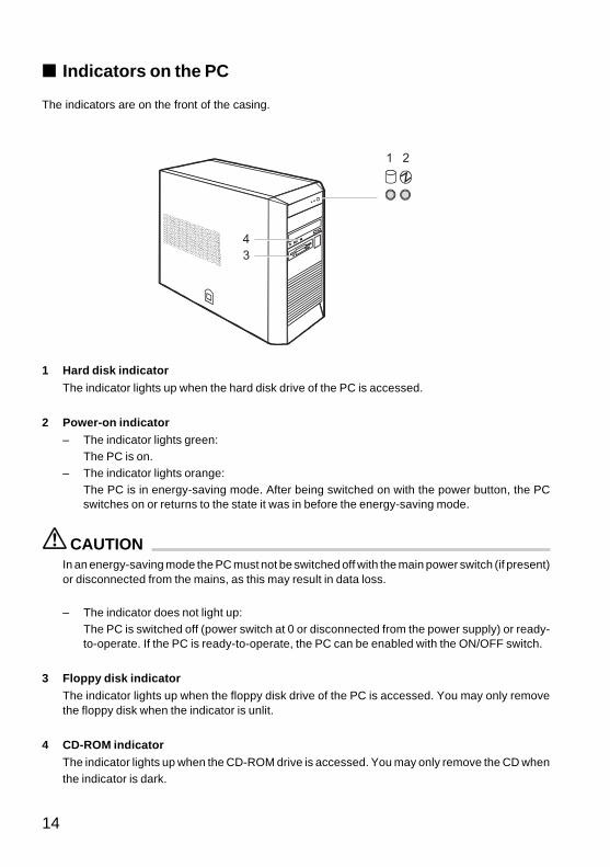
■ Indicators on the PC
The indicators are on the front of the casing.
21
43
1 Hard disk indicator
The indicator lights up when the hard disk drive of the PC is accessed.
2 Power-on indicator– The indicator lights green:
The PC is on.– The indicator lights orange:
The PC is in energy-saving mode. After being switched on with the power button, the PCswitches on or returns to the state it was in before the energy-saving mode.
CAUTIONIn an energy-saving mode the PC must not be switched off with the main power switch (if present)or disconnected from the mains, as this may result in data loss.
– The indicator does not light up:The PC is switched off (power switch at 0 or disconnected from the power supply) or ready-to-operate. If the PC is ready-to-operate, the PC can be enabled with the ON/OFF switch.
3 Floppy disk indicatorThe indicator lights up when the floppy disk drive of the PC is accessed. You may only removethe floppy disk when the indicator is unlit.
4 CD-ROM indicatorThe indicator lights up when the CD-ROM drive is accessed. You may only remove the CD whenthe indicator is dark.
CHAPTER 2 Washingtons (11-14) 12/8/03, 11:38 AM14
15
2 Keyboard
1
8 9 10 11 12 13 14 15 16 17 18 19
20
2 3 4 5 6 7
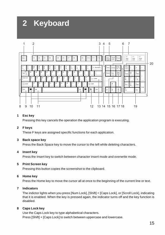
1 Esc keyPressing this key cancels the operation the application program is executing.
2 F keysThese F keys are assigned specific functions for each application.
3 Back space keyPress the Back Space key to move the cursor to the left while deleting characters.
4 Insert key
Press the Insert key to switch between character insert mode and overwrite mode.
5 Print Screen keyPressing this button copies the screenshot to the clipboard.
6 Home keyPress the Home key to move the cursor all at once to the beginning of the current line or text.
7 IndicatorsThe indictor lights when you press [Num Lock], [Shift] + [Caps Lock], or [Scroll Lock], indicatingthat it is enabled. When the key is pressed again, the indicator turns off and the key function isdisabled.
8 Caps Lock keyUse the Caps Lock key to type alphabetical characters.Press [Shift] + [Caps Lock] to switch between uppercase and lowercase.
CHAPTER 2 Washingtons (15-20) 12/8/03, 11:36 AM15
16
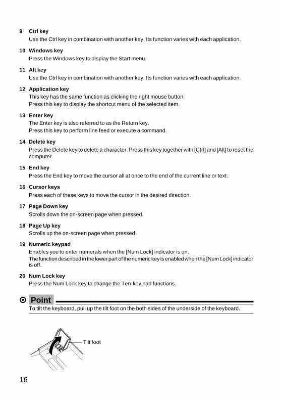
9 Ctrl keyUse the Ctrl key in combination with another key. Its function varies with each application.
10 Windows keyPress the Windows key to display the Start menu.
11 Alt keyUse the Ctrl key in combination with another key. Its function varies with each application.
12 Application keyThis key has the same function as clicking the right mouse button.Press this key to display the shortcut menu of the selected item.
13 Enter keyThe Enter key is also referred to as the Return key.Press this key to perform line feed or execute a command.
14 Delete keyPress the Delete key to delete a character. Press this key together with [Ctrl] and [Alt] to reset thecomputer.
15 End keyPress the End key to move the cursor all at once to the end of the current line or text.
16 Cursor keys
Press each of these keys to move the cursor in the desired direction.
17 Page Down key
Scrolls down the on-screen page when pressed.
18 Page Up keyScrolls up the on-screen page when pressed.
19 Numeric keypadEnables you to enter numerals when the [Num Lock] indicator is on.The function described in the lower part of the numeric key is enabled when the [Num Lock] indicatoris off.
20 Num Lock keyPress the Num Lock key to change the Ten-key pad functions.
����� PointTo tilt the keyboard, pull up the tilt foot on the both sides of the underside of the keyboard.
Tilt foot
CHAPTER 2 Washingtons (15-20) 12/8/03, 11:36 AM16
17
3 Floppy Disks
■ Working with Floppy Disks
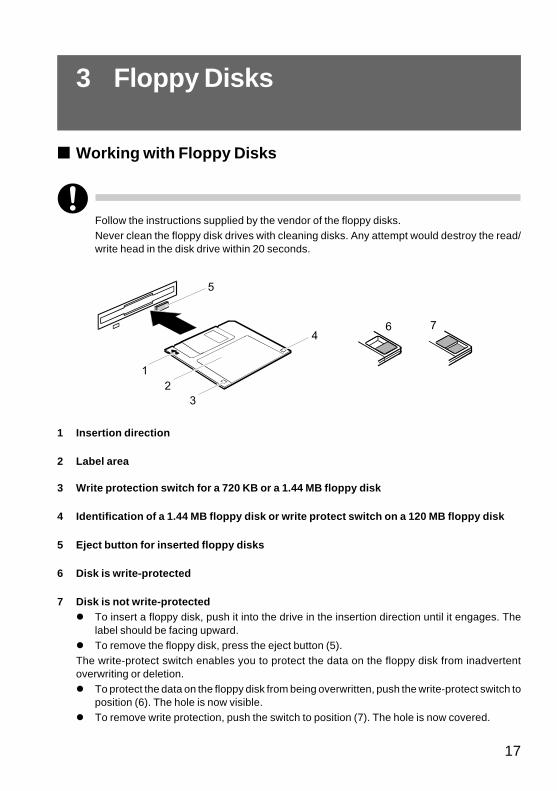
Follow the instructions supplied by the vendor of the floppy disks.Never clean the floppy disk drives with cleaning disks. Any attempt would destroy the read/write head in the disk drive within 20 seconds.
32
1
5
64
7
1 Insertion direction
2 Label area
3 Write protection switch for a 720 KB or a 1.44 MB floppy disk
4 Identification of a 1.44 MB floppy disk or write protect switch on a 120 MB floppy disk
5 Eject button for inserted floppy disks
6 Disk is write-protected
7 Disk is not write-protected� To insert a floppy disk, push it into the drive in the insertion direction until it engages. The
label should be facing upward.� To remove the floppy disk, press the eject button (5).The write-protect switch enables you to protect the data on the floppy disk from inadvertentoverwriting or deletion.� To protect the data on the floppy disk from being overwritten, push the write-protect switch to
position (6). The hole is now visible.� To remove write protection, push the switch to position (7). The hole is now covered.
CHAPTER 2 Washingtons (15-20) 12/8/03, 11:37 AM17
18
1
2
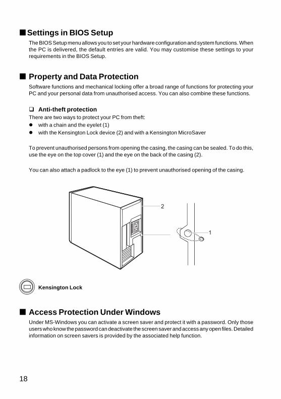
Kensington Lock
■ Access Protection Under WindowsUnder MS-Windows you can activate a screen saver and protect it with a password. Only thoseusers who know the password can deactivate the screen saver and access any open files. Detailedinformation on screen savers is provided by the associated help function.
■ Settings in BIOS SetupThe BIOS Setup menu allows you to set your hardware configuration and system functions. Whenthe PC is delivered, the default entries are valid. You may customise these settings to yourrequirements in the BIOS Setup.
■ Property and Data ProtectionSoftware functions and mechanical locking offer a broad range of functions for protecting yourPC and your personal data from unauthorised access. You can also combine these functions.
� Anti-theft protectionThere are two ways to protect your PC from theft:� with a chain and the eyelet (1)� with the Kensington Lock device (2) and with a Kensington MicroSaver
To prevent unauthorised persons from opening the casing, the casing can be sealed. To do this,use the eye on the top cover (1) and the eye on the back of the casing (2).
You can also attach a padlock to the eye (1) to prevent unauthorised opening of the casing.
CHAPTER 2 Washingtons (15-20) 12/8/03, 11:37 AM18
19
■ BIOS Setup Security FunctionsThe Security menu in BIOS Setup offers you various options for protecting your personal dataagainst unauthorised access, e.g.:� Preventing unauthorised BIOS Setup entry� Preventing unauthorised system access� Preventing unauthorised access to the settings of boards with their own BIOS� Preventing system booting from the diskette drive� Preventing unauthorised writing of diskettes� Protecting BIOS from being overwrittenYou can also combine these functions.
CHAPTER 2 Washingtons (15-20) 12/8/03, 11:37 AM19

20
CHAPTER 2 Wash2 (15-20) 12/8/03, 2:24 PM20

CHAPTER 3Troubleshooting
and Tips
CHAPTER 3 Washingtons (21-26) 12/8/03, 11:42 AM21
22
1 Troubleshooting and Tips
CAUTION
Take careful note of the safety warnings and in the “Preparing for Use” chapter, when you connector disconnect cables.
If a fault occurs, try to correct it as described:
� in this chapter
� in the documentation of the connected devices
� in the help systems of the software used.
If you fail to correct the problem, proceed as follows:
� Switch the PC off.
� Make a note of the steps and the circumstances that led to the fault.
� Make a note of any error messages displayed.
� Note the ID number of your device.
� Contact your sales outlet or our customer service centre.
■ Installing New SoftwareWhen installing programmes or drivers, important files may be overwritten and modified. To be ableto access the original data in the event of any problems following installation, you should backup yourhard disk prior to installation.
■ Power-on Indicator Remains Unlit After You HaveSwitched on Your Device
This may be due to the following:
The mains voltage supply is faulty
� Check that the power cable is plugged properly into the system unit and grounded mains outlet.
� Switch the PC on at the power switch.
Internal power supply overloaded
� Disconnect the power cable of the system unit from the grounded mains outlet.
� Wait for a moment.
� Plug the power cable into the grounded mains outlet again.
� Switch the PC on at the power switch.
CHAPTER 3 Wash2 (21-26) 12/8/03, 2:37 PM22
23
� The screen stays blankIf your screen remains blank this may be due to the following:
Monitor is switched off
� Switch your monitor on.
Power saving has been activated (screen is blank)
� Press any key on the keyboard.
or
� Deactivate the screen saver. Enter the appropriate password.
Brightness control is set too dark
� Adjust the brightness control. For detailed information, please refer to the operating manualsupplied with your monitor.
Power cable not connected� Switch off the monitor and the PC.
� Check that the power cable of the monitor is properly connected to the monitor and, dependingon the connector, to the system unit or to the grounded mains outlet.
� Check that the power cable of the PC is plugged properly into the system unit and grounded mainsoutlet.
� Switch on the monitor and the system unit.
Monitor cable not connected
� Switch off the monitor and the system unit.
� Check that the monitor cable is properly connected to the system unit and monitor.
� Switch on the monitor and the system unit.
CHAPTER 3 Washingtons (21-26) 12/8/03, 11:42 AM23
24
Wrong monitor has been set under Windows 2000/XP
� Restart the PC.
� If the message Starting Windows appears, press function key [F8].
The Windows 2000/XP Advanced Options Menu appears.
� Select Safe Mode or Safe Mode with Network.
� Set the correct values for the attached monitor as described in the operating manual of the monitorby selecting Start → Settings → Control Panel → Display → Settings.
The wrong RAM modules have been inserted
See the technical manual for the system board for information on which memory modules can beused.
■ No Mouse Pointer Displayed on the Screen� Shut down the operating system properly.
� Switch the PC off.
� Check that the mouse cable is properly connected to the system unit.
If you use an adapter or extension lead with the mouse cable, check the connections.
� Make sure that only one mouse is connected.
� Switch the PC on.
The mouse controller must be enabled if you use a PS/2 mouse on the PS/2 mouse port .
� Check in the BIOS Setup that the mouse controller is Enabled.
� Check that the mouse driver is properly installed and is present when the application programmeis started. Detailed information can be found in the user guide for the mouse and applicationprogramme.
■ The Floppy Disk Cannot be Read or Written� Check that the floppy disk is not write protected.
� Check the relevant entries for Diskette A: or B: in the Main menu of the BIOS Setup.
� Check that the floppy disk drive controller is enabled.
� Check that the cables of the floppy disk drive are properly connected (refer to “Changing the floppydisk drive” chapter).
CHAPTER 3 Washingtons (21-26) 12/8/03, 11:42 AM24
25
■ Time and/or Date is Not CorrectYou can set the time and date in the BIOS Setup or in the operating system.
� Set the time and date.
If the time and date are repeatedly wrong when you switch on your PC, the on-board batteryis flat. Change the lithium battery as described in the "Replacing lithium battery" chapter.
■ Tips
The PC cannot be switched off with the power button
Cause: The PC was not switched on with the power button.
� Press the power button again.
Cause: System crash
� Press and hold the power button for at least four seconds until the device switches off.
Out of system resources
If you have too many applications running at once, you may experience problems due to a lack of
system resources. In this case you should:
� close unnecessary applications
or
� run the applications in a different order.
CHAPTER 3 Washingtons (21-26) 12/8/03, 11:42 AM25

26
CHAPTER 3 Washingtons (21-26) 12/8/03, 11:42 AM26

CHAPTER 4System Expansion
CHAPTER 4 Washingtons (27-38) 12/8/03, 11:43 AM27
28
1 System Expansions
It may be necessary to update the BIOS when carrying out a system expansion or hardwareupgrade. In this case, please contact our customer service centre.When installing components with a high power loss, make sure that the maximum permissibletemperatures of the individual components are not exceeded.The device must be switched off when installing/removing the system expansions and maynot be in the Suspend mode.
This chapter describes all the activities required to modify your PC hardware (e.g. installing boardsor drives).
Read the supplied documentation before installing new drives and/or boards.
� Information about boardsTake care with the locking mechanisms (catches and centring pins) when you are replacing the systemboard or components on the system board.
To prevent damage to the system board or the components and conductors on it, please take carewhen you insert or remove boards. Make sure expansion boards are inserted straightly.
Never use sharp objects (screwdrivers) for leverage.
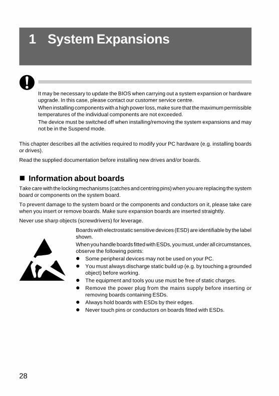
Boards with electrostatic sensitive devices (ESD) are identifiable by the labelshown.When you handle boards fitted with ESDs, you must, under all circumstances,observe the following points:� Some peripheral devices may not be used on your PC.� You must always discharge static build up (e.g. by touching a grounded
object) before working.� The equipment and tools you use must be free of static charges.� Remove the power plug from the mains supply before inserting or
removing boards containing ESDs.� Always hold boards with ESDs by their edges.� Never touch pins or conductors on boards fitted with ESDs.
CHAPTER 4 Washingtons (27-38) 12/8/03, 11:43 AM28
29
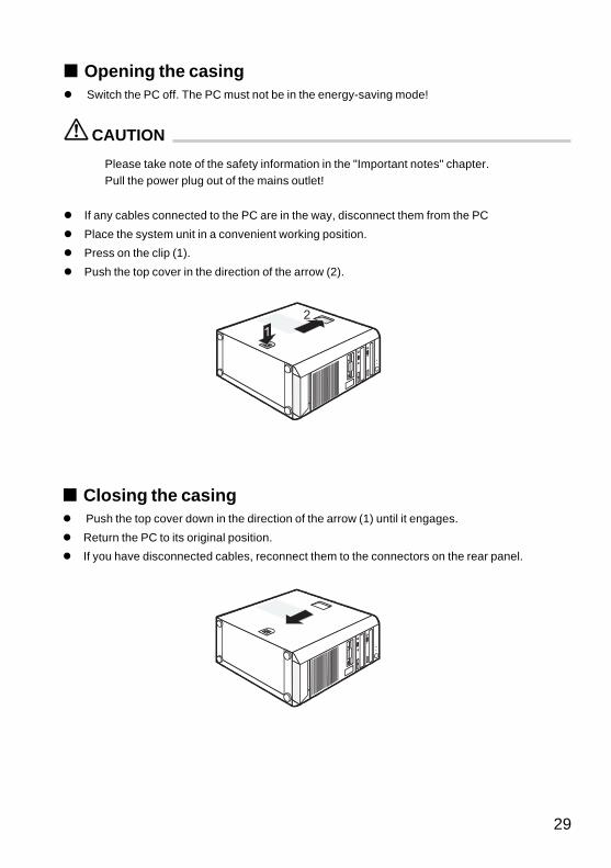
■ Opening the casing� Switch the PC off. The PC must not be in the energy-saving mode!
CAUTION
Please take note of the safety information in the "Important notes" chapter.Pull the power plug out of the mains outlet!
� If any cables connected to the PC are in the way, disconnect them from the PC
� Place the system unit in a convenient working position.
� Press on the clip (1).
� Push the top cover in the direction of the arrow (2).
■ Closing the casing� Push the top cover down in the direction of the arrow (1) until it engages.
� Return the PC to its original position.
� If you have disconnected cables, reconnect them to the connectors on the rear panel.
2
CHAPTER 4 Washingtons (27-38) 12/8/03, 11:43 AM29
30
■ Installing and removing a board
CAUTION
Please take note of the “Information about boards” chapter.
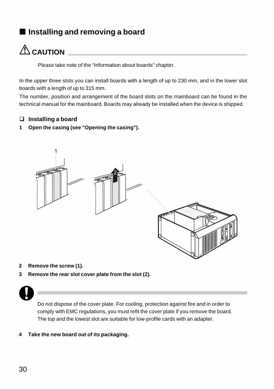
In the upper three slots you can install boards with a length of up to 230 mm, and in the lower slotboards with a length of up to 315 mm.
The number, position and arrangement of the board slots on the mainboard can be found in thetechnical manual for the mainboard. Boards may already be installed when the device is shipped.
� Installing a board1 Open the casing (see "Opening the casing").
1
2 Remove the screw (1).
3 Remove the rear slot cover plate from the slot (2).
Do not dispose of the cover plate. For cooling, protection against fire and in order tocomply with EMC regulations, you must refit the cover plate if you remove the board.The top and the lowest slot are suitable for low-profile cards with an adapter.
4 Take the new board out of its packaging.
CHAPTER 4 Washingtons (27-38) 12/8/03, 11:43 AM30
31
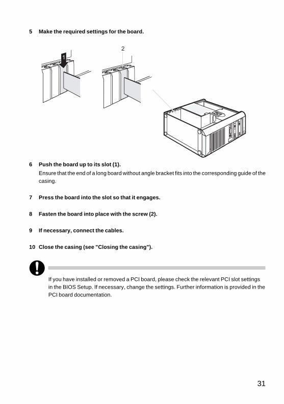
6 Push the board up to its slot (1).
Ensure that the end of a long board without angle bracket fits into the corresponding guide of thecasing.
7 Press the board into the slot so that it engages.
8 Fasten the board into place with the screw (2).
9 If necessary, connect the cables.
10 Close the casing (see "Closing the casing").
If you have installed or removed a PCI board, please check the relevant PCI slot settingsin the BIOS Setup. If necessary, change the settings. Further information is provided in thePCI board documentation.
2
5 Make the required settings for the board.
CHAPTER 4 Washingtons (27-38) 12/8/03, 11:43 AM31
32
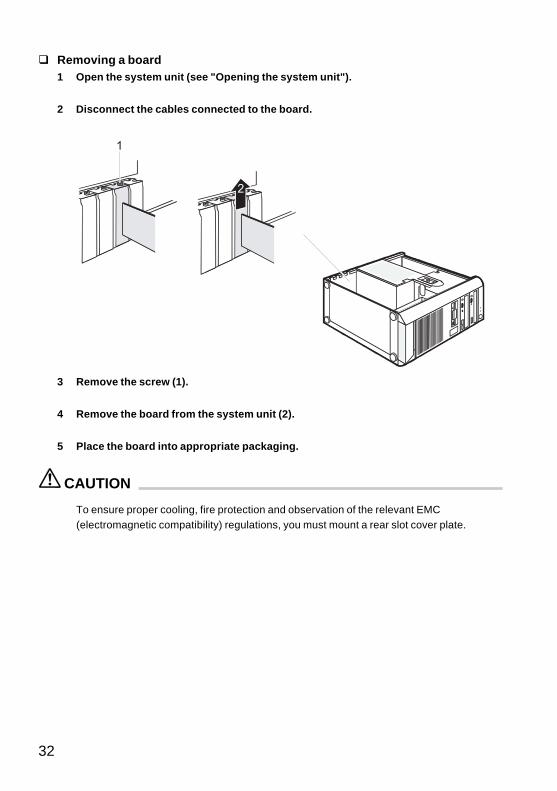
3 Remove the screw (1).
4 Remove the board from the system unit (2).
5 Place the board into appropriate packaging.
CAUTION
To ensure proper cooling, fire protection and observation of the relevant EMC(electromagnetic compatibility) regulations, you must mount a rear slot cover plate.
� Removing a board1 Open the system unit (see "Opening the system unit").
2 Disconnect the cables connected to the board.
1
CHAPTER 4 Washingtons (27-38) 12/8/03, 11:43 AM32
33
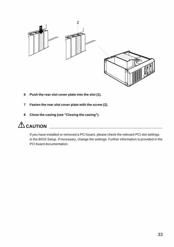
6 Push the rear slot cover plate into the slot (1).
7 Fasten the rear slot cover plate with the screw (2).
8 Close the casing (see "Closing the casing").
CAUTION
If you have installed or removed a PCI board, please check the relevant PCI slot settingsin the BIOS Setup. If necessary, change the settings. Further information is provided in thePCI board documentation.
2
CHAPTER 4 Washingtons (27-38) 12/8/03, 11:43 AM33
34
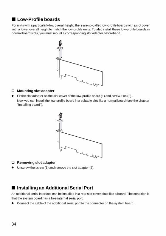
■ Low-Profile boardsFor units with a particularly low overall height, there are so-called low-profile boards with a slot coverwith a lower overall height to match the low-profile units. To also install these low-profile boards innormal board slots, you must mount a corresponding slot adapter beforehand.
� Mounting slot adapter� Fit the slot adapter on the slot cover of the low-profile board (1) and screw it on (2).
Now you can install the low-profile board in a suitable slot like a normal board (see the chapter"Installing board").
� Removing slot adapter� Unscrew the screw (1) and remove the slot adapter (2).
2
1
■ Installing an Additional Serial PortAn additional serial interface can be installed in a rear slot cover plate like a board. The condition isthat the system board has a free internal serial port.
� Connect the cable of the additional serial port to the connector on the system board.
CHAPTER 4 Washingtons (27-38) 12/8/03, 11:43 AM34
35
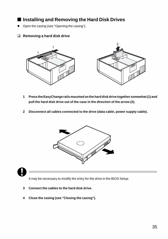
■ Installing and Removing the Hard Disk Drives� Open the casing (see "Opening the casing").
� Removing a hard disk drive
1 Press the EasyChange rails mounted on the hard disk drive together somewhat (1) and
pull the hard disk drive out of the case in the direction of the arrow (2).
2 Disconnect all cables connected to the drive (data cable, power supply cable).
1
12
It may be necessary to modify the entry for the drive in the BIOS Setup.
3 Connect the cables to the hard disk drive.
4 Close the casing (see "Closing the casing").
CHAPTER 4 Washingtons (27-38) 12/8/03, 11:44 AM35
36
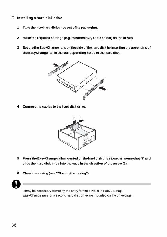
� Installing a hard disk drive
1 Take the new hard disk drive out of its packaging.
2 Make the required settings (e.g. master/slave, cable select) on the drives.
3 Secure the EasyChange rails on the side of the hard disk by inserting the upper pins of
the EasyChange rail in the corresponding holes of the hard disk.
4 Connect the cables to the hard disk drive.
5 Press the EasyChange rails mounted on the hard disk drive together somewhat (1) and
slide the hard disk drive into the case in the direction of the arrow (2).
6 Close the casing (see "Closing the casing").
It may be necessary to modify the entry for the drive in the BIOS Setup.EasyChange rails for a second hard disk drive are mounted on the drive cage.
1
12
CHAPTER 4 Washingtons (27-38) 12/8/03, 11:44 AM36
37
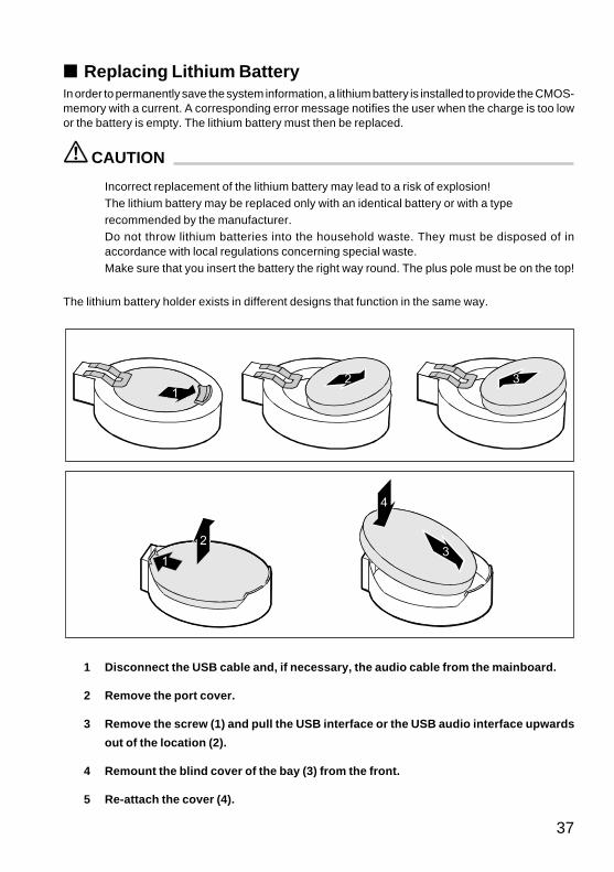
■ Replacing Lithium BatteryIn order to permanently save the system information, a lithium battery is installed to provide the CMOS-memory with a current. A corresponding error message notifies the user when the charge is too lowor the battery is empty. The lithium battery must then be replaced.
CAUTION
Incorrect replacement of the lithium battery may lead to a risk of explosion!The lithium battery may be replaced only with an identical battery or with a typerecommended by the manufacturer.Do not throw lithium batteries into the household waste. They must be disposed of inaccordance with local regulations concerning special waste.Make sure that you insert the battery the right way round. The plus pole must be on the top!
The lithium battery holder exists in different designs that function in the same way.
1 Disconnect the USB cable and, if necessary, the audio cable from the mainboard.
2 Remove the port cover.
3 Remove the screw (1) and pull the USB interface or the USB audio interface upwards
out of the location (2).
4 Remount the blind cover of the bay (3) from the front.
5 Re-attach the cover (4).
CHAPTER 4 Washingtons (27-38) 12/8/03, 11:44 AM37

38
CHAPTER 4 Washingtons (27-38) 12/8/03, 11:44 AM38

CHAPTER 5Technical Data
CHAPTER 5 Washingtons (39-40) 12/8/03, 11:45 AM39
40
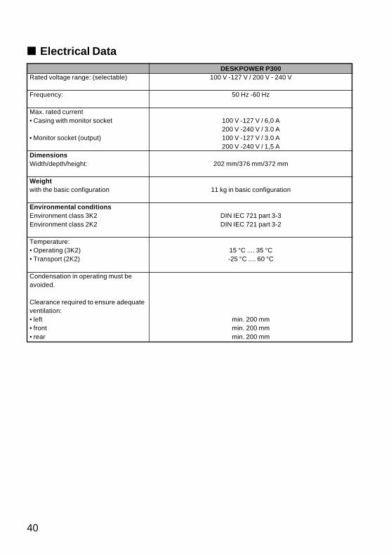
■ Electrical Data
Rated voltage range: (selectable)
Frequency:
Max. rated current• Casing with monitor socket
• Monitor socket (output)
DimensionsWidth/depth/height:
Weightwith the basic configuration
Environmental conditionsEnvironment class 3K2Environment class 2K2
Temperature:• Operating (3K2)• Transport (2K2)
Condensation in operating must beavoided.
Clearance required to ensure adequateventilation:• left• front• rear
DESKPOWER P300100 V -127 V / 200 V - 240 V
50 Hz -60 Hz
100 V -127 V / 6,0 A200 V -240 V / 3.0 A100 V -127 V / 3.0 A200 V -240 V / 1,5 A
202 mm/376 mm/372 mm
11 kg in basic configuration
DIN IEC 721 part 3-3DIN IEC 721 part 3-2
15 °C .... 35 °C-25 °C .... 60 °C
min. 200 mmmin. 200 mmmin. 200 mm
CHAPTER 5 Washingtons (39-40) 12/8/03, 11:45 AM40