Embed Size (px)
Citation preview

i
Desk Fan Airflow Redesign
ME 4041: Computer Graphics and CAD
Group Members:
Timothy Ibru
Steven Jones
Alex Koltsidopoulos Papatzimos
ii
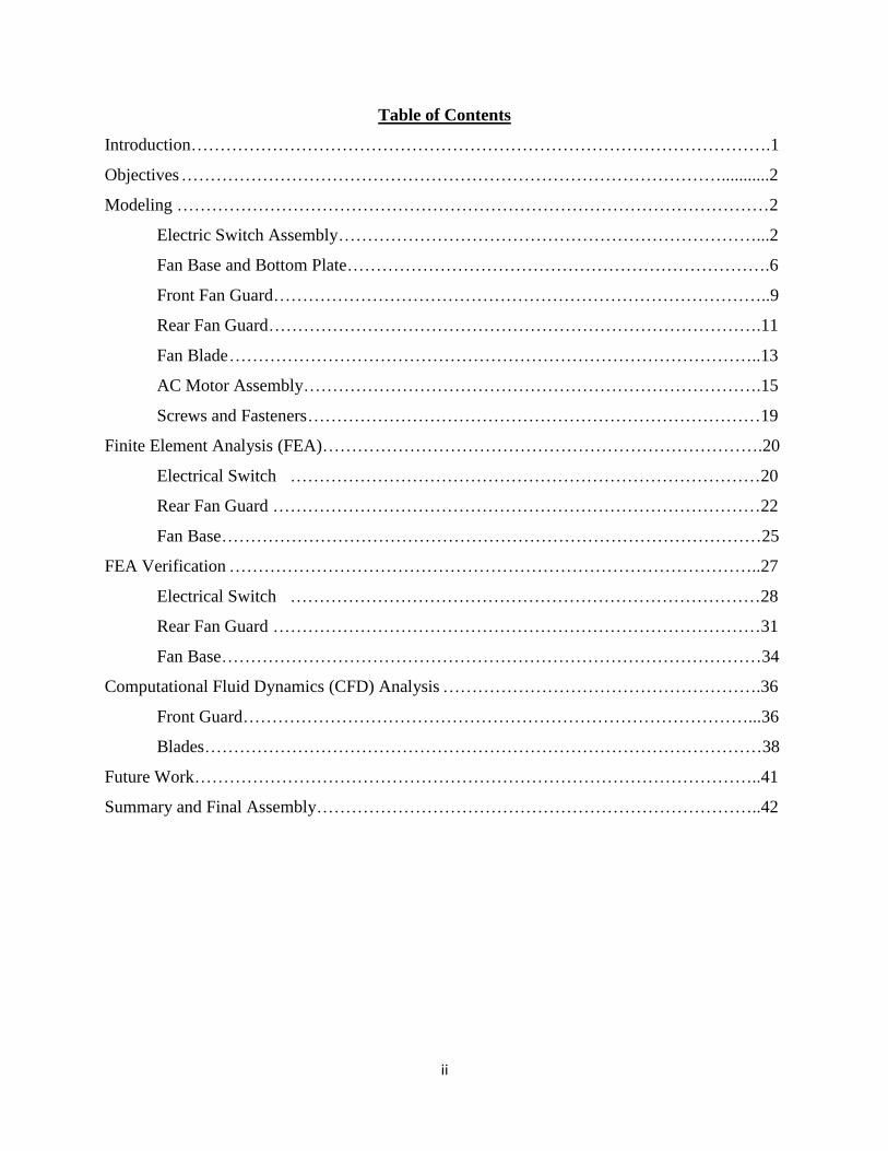
Table of Contents
Introduction……………………………………………………………………………………….1
Objectives …………………………………………………………………………………...........2
Modeling …………………………………………………………………………………………2
Electric Switch Assembly………………………………………………………………...2
Fan Base and Bottom Plate……………………………………………………………….6
Front Fan Guard…………………………………………………………………………..9
Rear Fan Guard………………………………………………………………………….11
Fan Blade ………………………………………………………………………………..13
AC Motor Assembly…………………………………………………………………….15
Screws and Fasteners ……………………………………………………………………19
Finite Element Analysis (FEA)………………………………………………………………….20
Electrical Switch ………………………………………………………………………20
Rear Fan Guard …………………………………………………………………………22
Fan Base…………………………………………………………………………………25
FEA Verification ………………………………………………………………………………..27
Electrical Switch ………………………………………………………………………28
Rear Fan Guard …………………………………………………………………………31
Fan Base…………………………………………………………………………………34
Computational Fluid Dynamics (CFD) Analysis ……………………………………………….36
Front Guard……………………………………………………………………………...36
Blades……………………………………………………………………………………38
Future Work……………………………………………………………………………………..41
Summary and Final Assembly…………………………………………………………………..42
1
Introduction
The selected device for this project is a common desktop fan. Various versions and
models of the device exist but all possess the same fundamental design. This means that they all
share the same basic functionality and subsequently, the same inherent design flaws. Desktop
fans have a broad market but the main customers would be workers and students who find
themselves constrained to desks for long periods of time and require ventilation that is not
suitably provided. These will be the main target for design improvements for this project.
The functioning of the device involves the rotation of broad fan blades to induce the
required airflow. The airflow is directed through a mesh frame that shields the rotating blades to
avoid dangerous interaction with the user. Much room is left for improvement and the broad
objective is to improve upon the current design to create a better device.
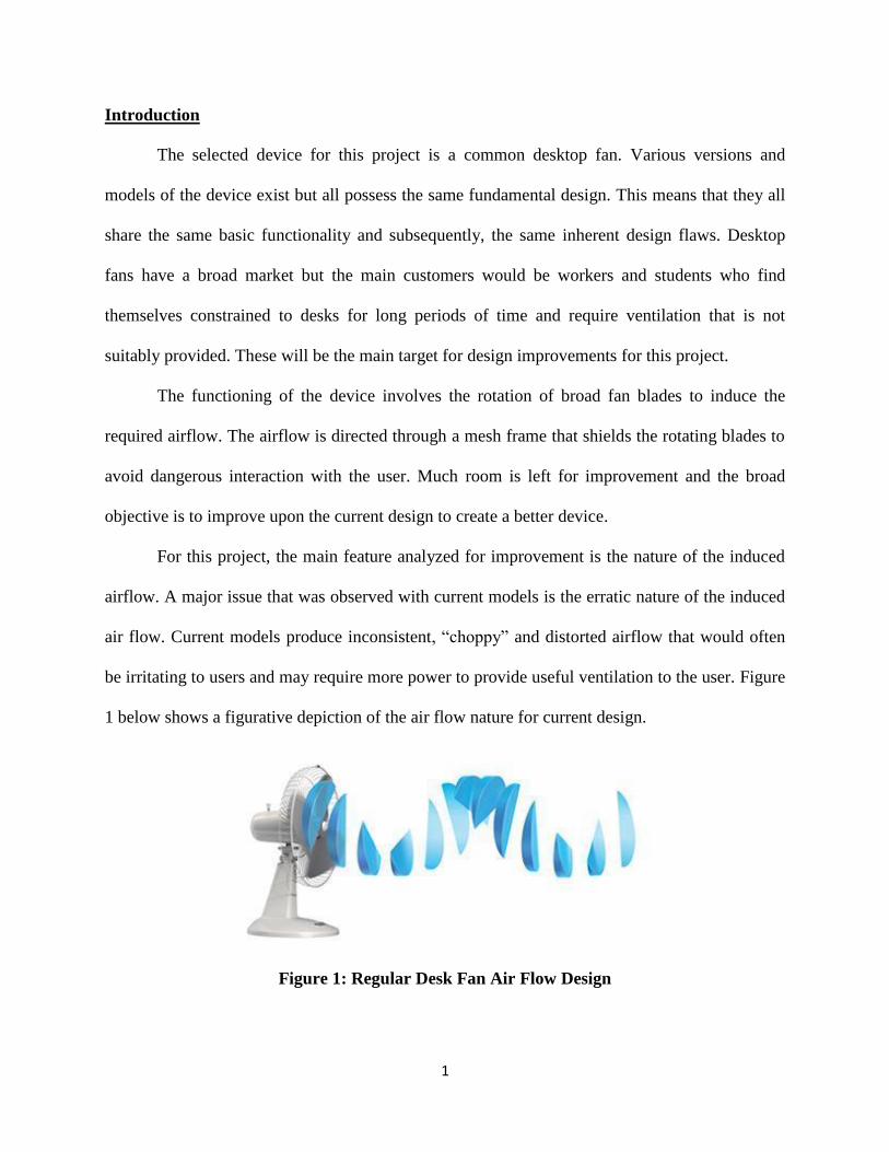
For this project, the main feature analyzed for improvement is the nature of the induced
airflow. A major issue that was observed with current models is the erratic nature of the induced
air flow. Current models produce inconsistent, “choppy” and distorted airflow that would often
be irritating to users and may require more power to provide useful ventilation to the user. Figure
1 below shows a figurative depiction of the air flow nature for current design.
Figure 1: Regular Desk Fan Air Flow Design
2
For the project, this airflow problem is analyzed with the goal of developing a design that
allows for a more uniform airflow that would be more satisfactory to the user.
Objective
The objective of this project is to provide design improvements to the current desk fan
design. The primary goal is to improve the nature of the generated airflow but considerations
would also be made for durability and structural integrity by evaluating, and modifying if
necessary, the critical structural components that are prone to damaging loading conditions.
Modeling
Before analyses and modifications could be made on the device, the components of the
device were modelled and assembled using the NX modeling tool. Below is an outline of the
modeling and assembly process.
Modeling: Electric Switch Assembly:
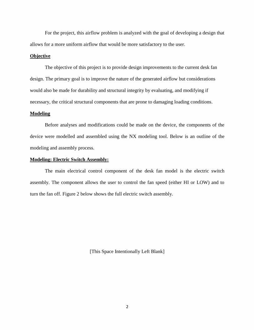
The main electrical control component of the desk fan model is the electric switch
assembly. The component allows the user to control the fan speed (either HI or LOW) and to
turn the fan off. Figure 2 below shows the full electric switch assembly.
[This Space Intentionally Left Blank]
3
Figure 2: Electric switch complete assembly.
The assembly comprised 3 individual components which include the electric switch, the electric
switch module, and the electric switch mounting bracket. The following subsections provide a
brief description of the main steps followed when modeling the parts.
Electric Switch
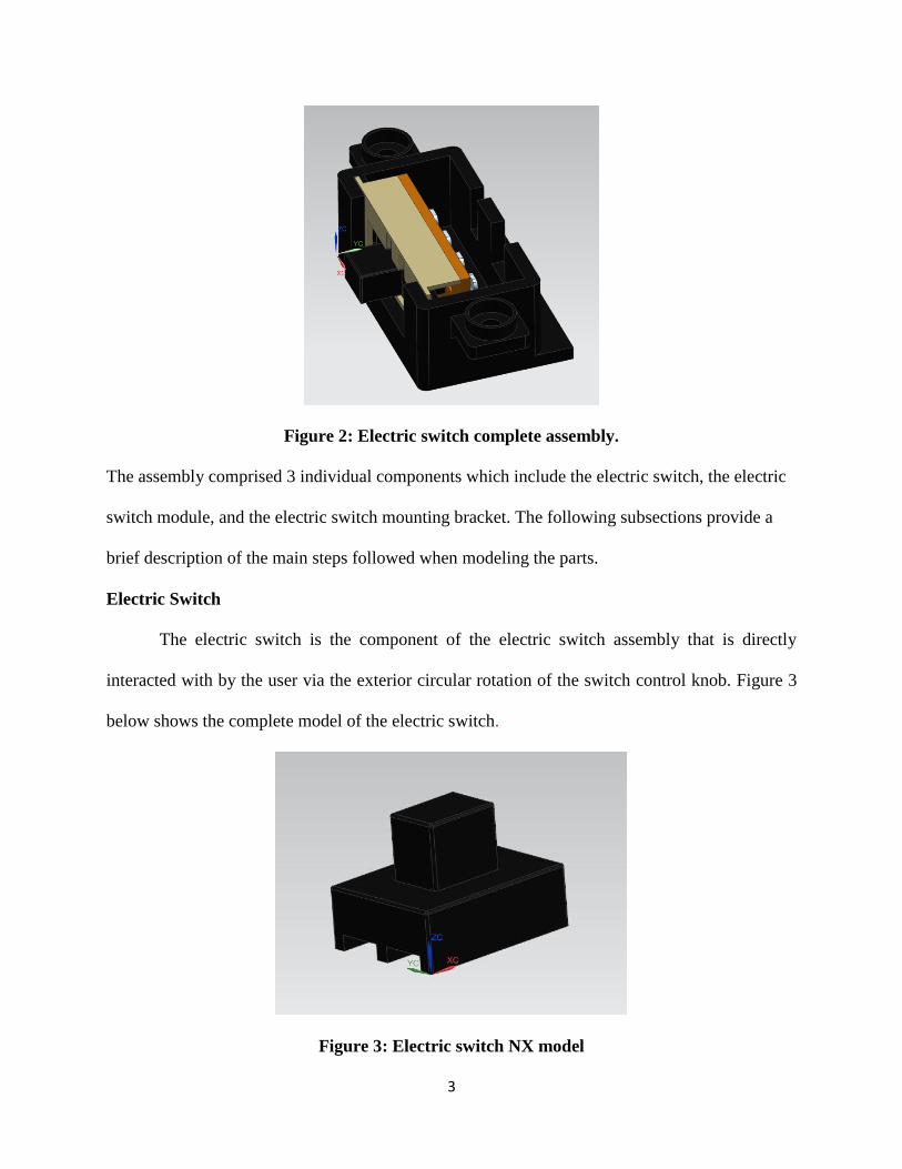
The electric switch is the component of the electric switch assembly that is directly
interacted with by the user via the exterior circular rotation of the switch control knob. Figure 3
below shows the complete model of the electric switch.
Figure 3: Electric switch NX model
4
The scaled NX model of the electric switch was constructed by first measuring the
physical dimensions of the actual electric switch. These dimensions were then used to create
sketches of the electric switch profile. The NX extrusion was used to create the general shape of
the switch from the profile sketches. To give a better resemblance to the actual part, minor edge
blends were added and the color adjusted to mimic the color of the actual part.
Electric Switch Module
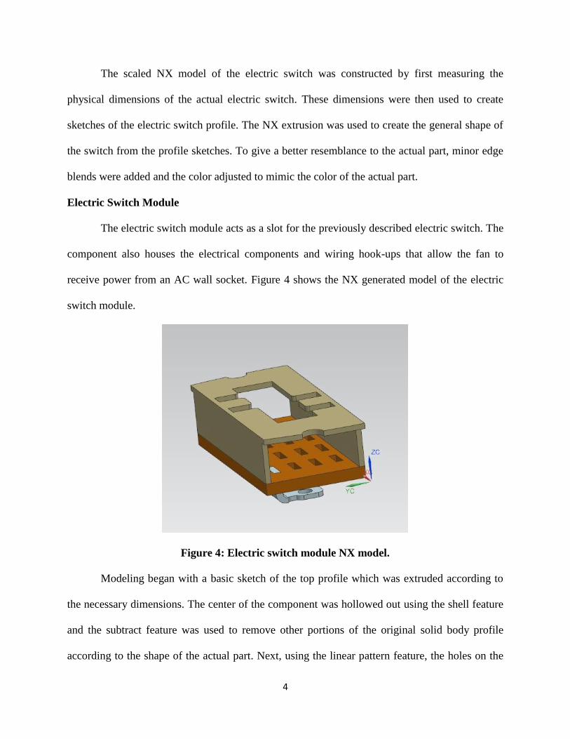
The electric switch module acts as a slot for the previously described electric switch. The
component also houses the electrical components and wiring hook-ups that allow the fan to
receive power from an AC wall socket. Figure 4 shows the NX generated model of the electric
switch module.
Figure 4: Electric switch module NX model.
Modeling began with a basic sketch of the top profile which was extruded according to
the necessary dimensions. The center of the component was hollowed out using the shell feature
and the subtract feature was used to remove other portions of the original solid body profile
according to the shape of the actual part. Next, using the linear pattern feature, the holes on the
5
rear of the part were constructed using extrude subtractions. Similarly, the top hole of the part
was made using an extruded subtraction of the desired profile made from a sketch on the top
surface of the part. Finally, using a combination of profile extrusions with other sketch profile
subtraction the wire connection probes on the bottom of the part were constructed. The piece was
finished by adding coloring to resemble the brass of the top portion, the plastic of the bottom
plate, and aluminum of the wire connections.
Electric Switch Mounting Bracket
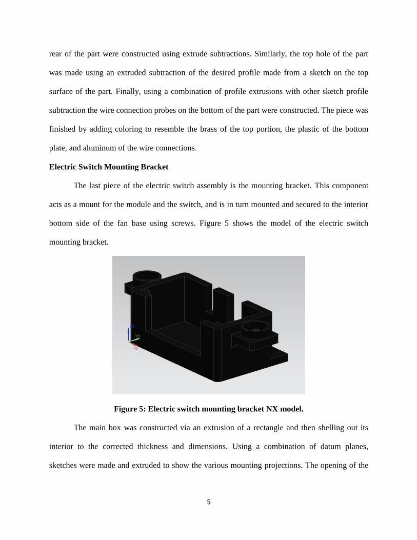
The last piece of the electric switch assembly is the mounting bracket. This component
acts as a mount for the module and the switch, and is in turn mounted and secured to the interior
bottom side of the fan base using screws. Figure 5 shows the model of the electric switch
mounting bracket.
Figure 5: Electric switch mounting bracket NX model.
The main box was constructed via an extrusion of a rectangle and then shelling out its
interior to the corrected thickness and dimensions. Using a combination of datum planes,
sketches were made and extruded to show the various mounting projections. The opening of the
6
component was modelled using the subtract feature, and then to further improve the resemblance
to the actual part, edge blends and color adjustments were used as necessary.
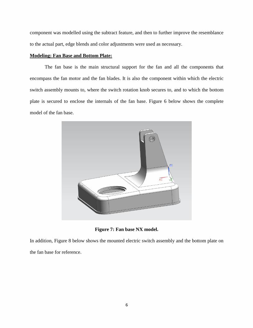
Modeling: Fan Base and Bottom Plate:
The fan base is the main structural support for the fan and all the components that
encompass the fan motor and the fan blades. It is also the component within which the electric
switch assembly mounts to, where the switch rotation knob secures to, and to which the bottom
plate is secured to enclose the internals of the fan base. Figure 6 below shows the complete
model of the fan base.
Figure 7: Fan base NX model.
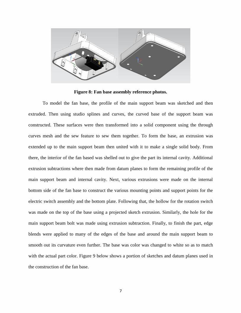
In addition, Figure 8 below shows the mounted electric switch assembly and the bottom plate on
the fan base for reference.
7
To model the fan base, the profile of the main support beam was sketched and then
extruded. Then using studio splines and curves, the curved base of the support beam was
constructed. These surfaces were then transformed into a solid component using the through
curves mesh and the sew feature to sew them together. To form the base, an extrusion was
extended up to the main support beam then united with it to make a single solid body. From
there, the interior of the fan based was shelled out to give the part its internal cavity. Additional
extrusion subtractions where then made from datum planes to form the remaining profile of the
main support beam and internal cavity. Next, various extrusions were made on the internal
bottom side of the fan base to construct the various mounting points and support points for the
electric switch assembly and the bottom plate. Following that, the hollow for the rotation switch
was made on the top of the base using a projected sketch extrusion. Similarly, the hole for the
main support beam bolt was made using extrusion subtraction. Finally, to finish the part, edge
blends were applied to many of the edges of the base and around the main support beam to
smooth out its curvature even further. The base was color was changed to white so as to match
with the actual part color. Figure 9 below shows a portion of sketches and datum planes used in
the construction of the fan base.
Figure 8: Fan base assembly reference photos.
8
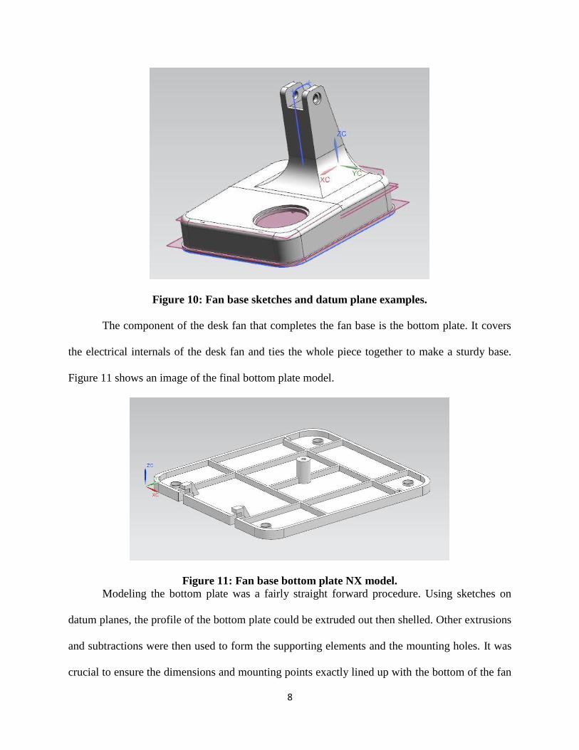
Figure 10: Fan base sketches and datum plane examples.
The component of the desk fan that completes the fan base is the bottom plate. It covers
the electrical internals of the desk fan and ties the whole piece together to make a sturdy base.
Figure 11 shows an image of the final bottom plate model.
Figure 11: Fan base bottom plate NX model.
Modeling the bottom plate was a fairly straight forward procedure. Using sketches on
datum planes, the profile of the bottom plate could be extruded out then shelled. Other extrusions
and subtractions were then used to form the supporting elements and the mounting holes. It was
crucial to ensure the dimensions and mounting points exactly lined up with the bottom of the fan
9
base. The use of calipers for the actual part measurements and dimensional measurement checks
with NX allowed for the proper alignment of the two parts.
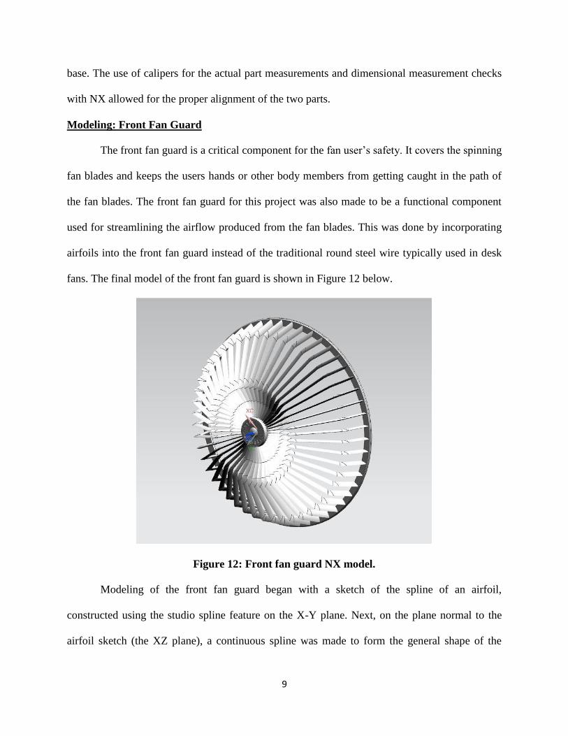
Modeling: Front Fan Guard
The front fan guard is a critical component for the fan user’s safety. It covers the spinning
fan blades and keeps the users hands or other body members from getting caught in the path of
the fan blades. The front fan guard for this project was also made to be a functional component
used for streamlining the airflow produced from the fan blades. This was done by incorporating
airfoils into the front fan guard instead of the traditional round steel wire typically used in desk
fans. The final model of the front fan guard is shown in Figure 12 below.
Figure 12: Front fan guard NX model.
Modeling of the front fan guard began with a sketch of the spline of an airfoil,
constructed using the studio spline feature on the X-Y plane. Next, on the plane normal to the
airfoil sketch (the XZ plane), a continuous spline was made to form the general shape of the
10
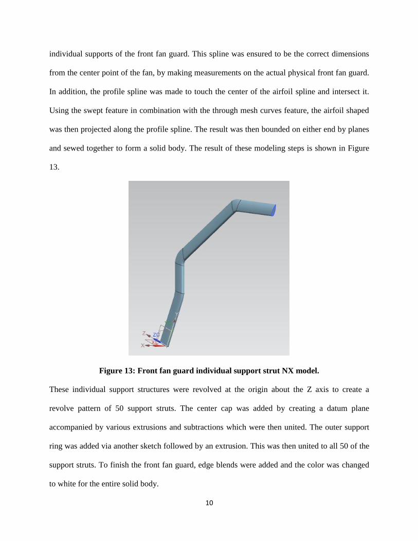
individual supports of the front fan guard. This spline was ensured to be the correct dimensions
from the center point of the fan, by making measurements on the actual physical front fan guard.
In addition, the profile spline was made to touch the center of the airfoil spline and intersect it.
Using the swept feature in combination with the through mesh curves feature, the airfoil shaped
was then projected along the profile spline. The result was then bounded on either end by planes
and sewed together to form a solid body. The result of these modeling steps is shown in Figure
13.
Figure 13: Front fan guard individual support strut NX model.
These individual support structures were revolved at the origin about the Z axis to create a
revolve pattern of 50 support struts. The center cap was added by creating a datum plane
accompanied by various extrusions and subtractions which were then united. The outer support
ring was added via another sketch followed by an extrusion. This was then united to all 50 of the
support struts. To finish the front fan guard, edge blends were added and the color was changed
to white for the entire solid body.
11
Modeling: Rear Fan Guard
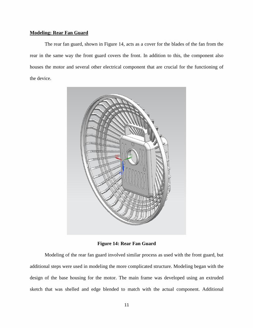
The rear fan guard, shown in Figure 14, acts as a cover for the blades of the fan from the
rear in the same way the front guard covers the front. In addition to this, the component also
houses the motor and several other electrical component that are crucial for the functioning of
the device.
Figure 14: Rear Fan Guard
Modeling of the rear fan guard involved similar process as used with the front guard, but
additional steps were used in modeling the more complicated structure. Modeling began with the
design of the base housing for the motor. The main frame was developed using an extruded
sketch that was shelled and edge blended to match with the actual component. Additional
12
features were added using sketches that were extruded with the use of the subtract or unite
commands as necessary.
The frame was modelled following using similar steps as with the front guard, except that
here, in developing the support structures, the thicken command was more efficient and thus
used in transforming the sketch to a solid shape. This was due to the relative simplicity of the
support structures. Also, the ring supports were incorporated into the sketch of the individual
support structures and revolved after the circular pattern of the main support was performed.
Edge blends were applied to match the form of the actual component and the individual
components merged using the unite command.
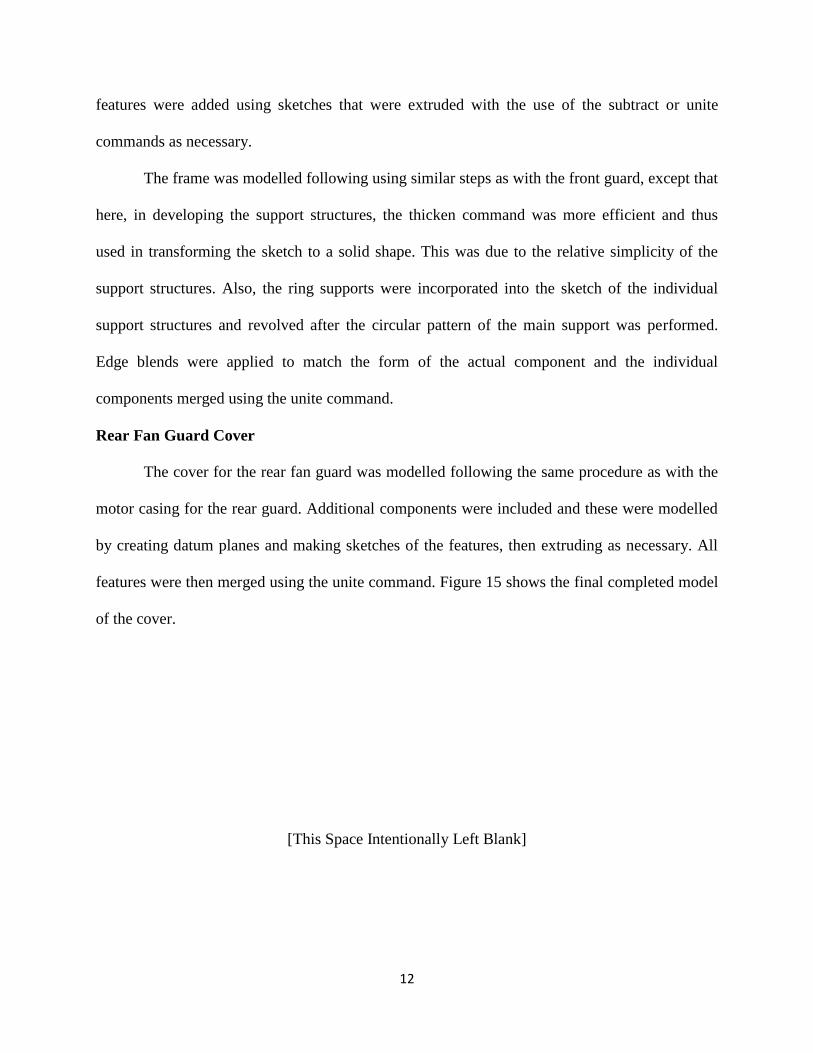
Rear Fan Guard Cover
The cover for the rear fan guard was modelled following the same procedure as with the
motor casing for the rear guard. Additional components were included and these were modelled
by creating datum planes and making sketches of the features, then extruding as necessary. All
features were then merged using the unite command. Figure 15 shows the final completed model
of the cover.
[This Space Intentionally Left Blank]
13
Figure 15: Rear Fan Guard Cover
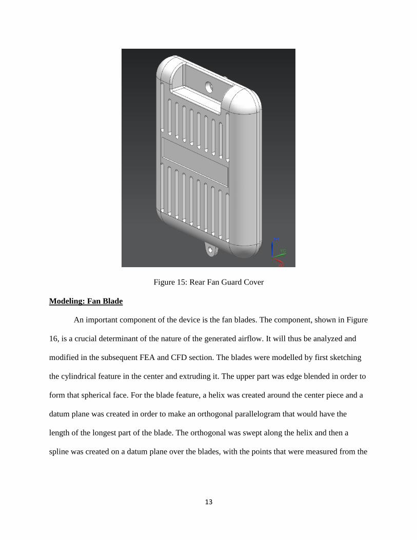
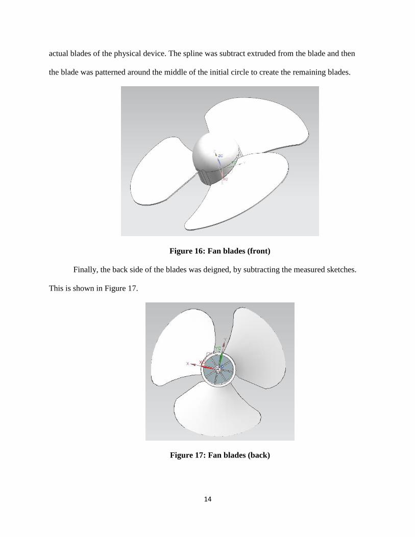
Modeling: Fan Blade
An important component of the device is the fan blades. The component, shown in Figure
16, is a crucial determinant of the nature of the generated airflow. It will thus be analyzed and
modified in the subsequent FEA and CFD section. The blades were modelled by first sketching
the cylindrical feature in the center and extruding it. The upper part was edge blended in order to
form that spherical face. For the blade feature, a helix was created around the center piece and a
datum plane was created in order to make an orthogonal parallelogram that would have the
length of the longest part of the blade. The orthogonal was swept along the helix and then a
spline was created on a datum plane over the blades, with the points that were measured from the
14
actual blades of the physical device. The spline was subtract extruded from the blade and then
the blade was patterned around the middle of the initial circle to create the remaining blades.
Figure 16: Fan blades (front)
Finally, the back side of the blades was deigned, by subtracting the measured sketches.
This is shown in Figure 17.
Figure 17: Fan blades (back)
15
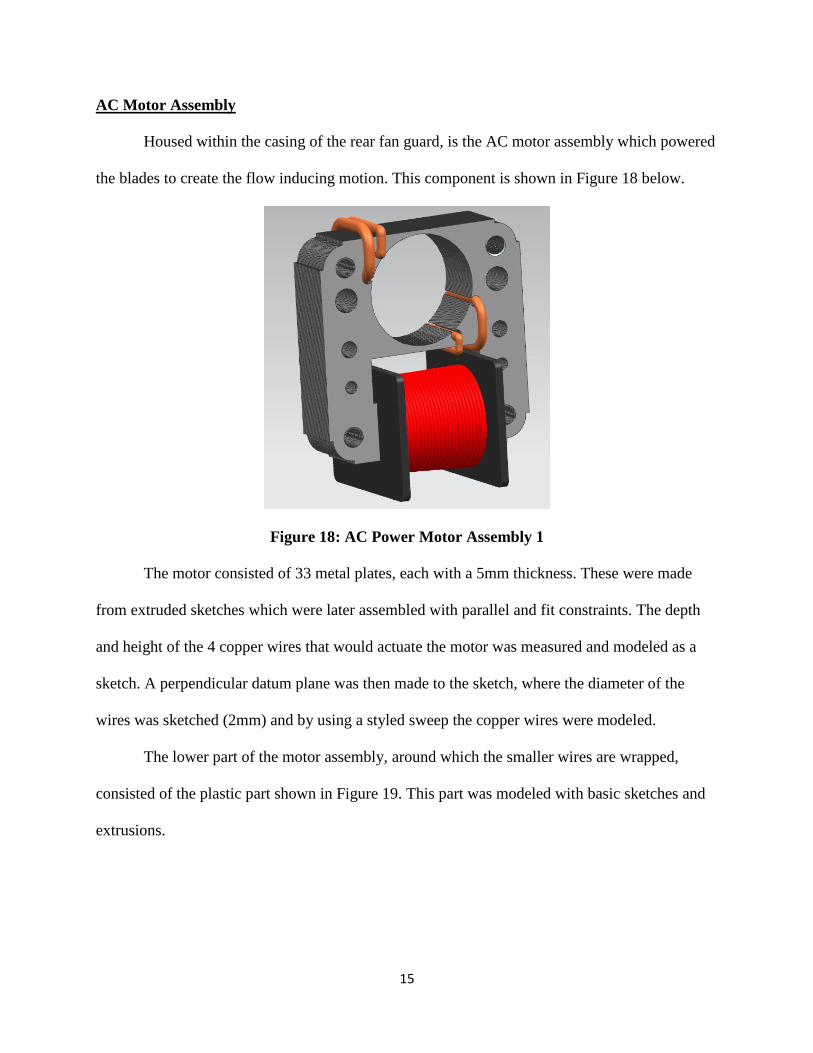
AC Motor Assembly
Housed within the casing of the rear fan guard, is the AC motor assembly which powered
the blades to create the flow inducing motion. This component is shown in Figure 18 below.
Figure 18: AC Power Motor Assembly 1
The motor consisted of 33 metal plates, each with a 5mm thickness. These were made
from extruded sketches which were later assembled with parallel and fit constraints. The depth
and height of the 4 copper wires that would actuate the motor was measured and modeled as a
sketch. A perpendicular datum plane was then made to the sketch, where the diameter of the
wires was sketched (2mm) and by using a styled sweep the copper wires were modeled.
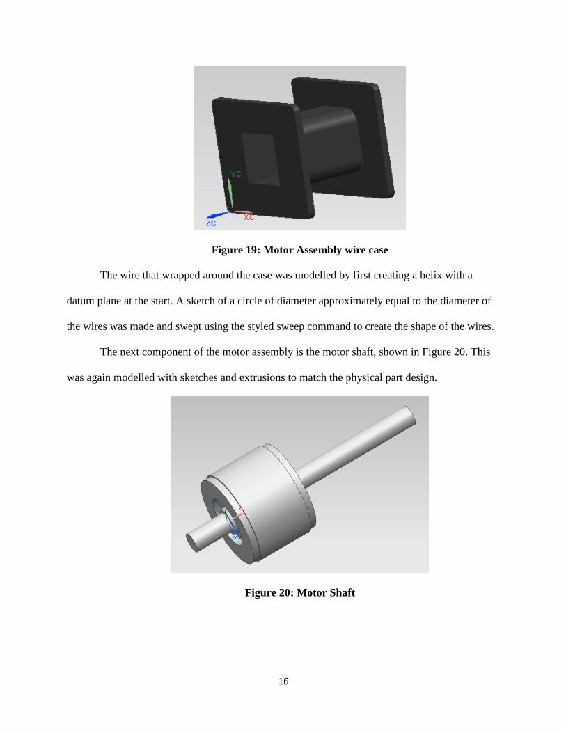
The lower part of the motor assembly, around which the smaller wires are wrapped,
consisted of the plastic part shown in Figure 19. This part was modeled with basic sketches and
extrusions.
16
Figure 19: Motor Assembly wire case
The wire that wrapped around the case was modelled by first creating a helix with a
datum plane at the start. A sketch of a circle of diameter approximately equal to the diameter of
the wires was made and swept using the styled sweep command to create the shape of the wires.
The next component of the motor assembly is the motor shaft, shown in Figure 20. This
was again modelled with sketches and extrusions to match the physical part design.
Figure 20: Motor Shaft
17
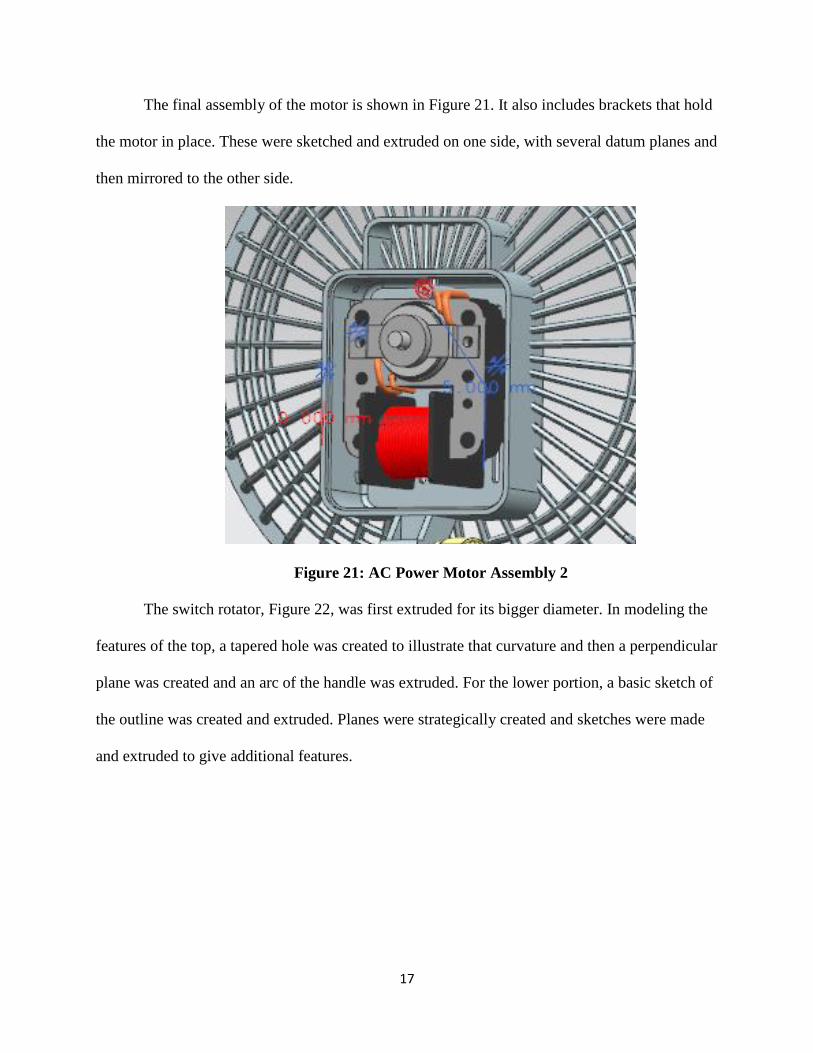
The final assembly of the motor is shown in Figure 21. It also includes brackets that hold
the motor in place. These were sketched and extruded on one side, with several datum planes and
then mirrored to the other side.
Figure 21: AC Power Motor Assembly 2
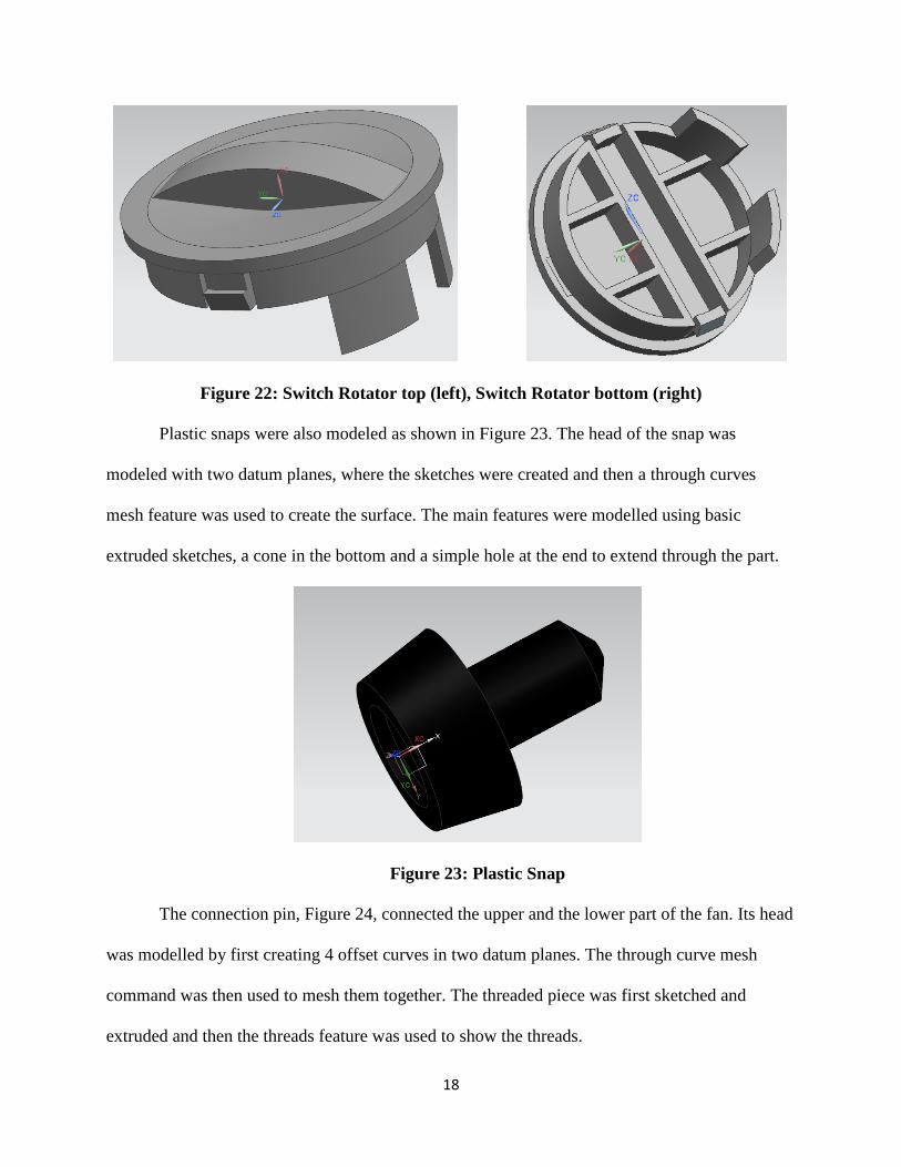
The switch rotator, Figure 22, was first extruded for its bigger diameter. In modeling the
features of the top, a tapered hole was created to illustrate that curvature and then a perpendicular
plane was created and an arc of the handle was extruded. For the lower portion, a basic sketch of
the outline was created and extruded. Planes were strategically created and sketches were made
and extruded to give additional features.
18
Figure 22: Switch Rotator top (left), Switch Rotator bottom (right)
Plastic snaps were also modeled as shown in Figure 23. The head of the snap was
modeled with two datum planes, where the sketches were created and then a through curves
mesh feature was used to create the surface. The main features were modelled using basic
extruded sketches, a cone in the bottom and a simple hole at the end to extend through the part.
Figure 23: Plastic Snap
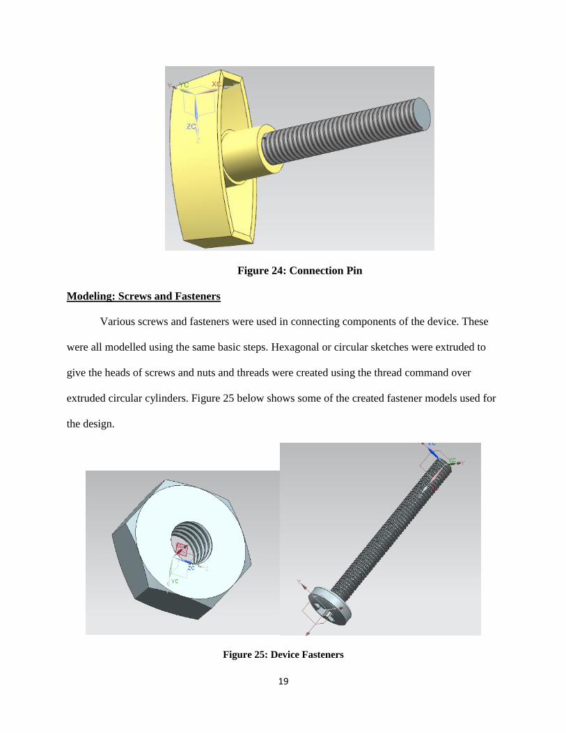
The connection pin, Figure 24, connected the upper and the lower part of the fan. Its head
was modelled by first creating 4 offset curves in two datum planes. The through curve mesh
command was then used to mesh them together. The threaded piece was first sketched and
extruded and then the threads feature was used to show the threads.
19
Figure 24: Connection Pin
Modeling: Screws and Fasteners
Various screws and fasteners were used in connecting components of the device. These
were all modelled using the same basic steps. Hexagonal or circular sketches were extruded to
give the heads of screws and nuts and threads were created using the thread command over
extruded circular cylinders. Figure 25 below shows some of the created fastener models used for
the design.
Figure 25: Device Fasteners
20
Finite Element Analysis
Although the major changes to be incorporated showed no apparent changes to structural
integrity, it was concluded that an analysis of some of the existing features most prone to failure
would be helpful in providing insight into the possible need for additional modifications. The
critical component of the current design were isolated and analyzed using NX FEA methods.
These results were verified using approximations and hand calculations. The parts selected
include the electrical switch, the rear fan guard and the base structure. These parts were assumed
to be made of ABS plastic for analysis purposes.
FEA Simulation: Electrical Switch
The electrical switch was determined during the preliminary design stages to be a critical
component for which it would be necessary to conduct an FEA on so as to understand the
deflections it undergoes. Because the switch will constantly be forced between the on and off
positions, it was critical to determine whether the switch could withstand the force of a person
pressing hard on the switch. It was determined that the mean index finger force a person can
press at is 45.96 N (Astin 1999).
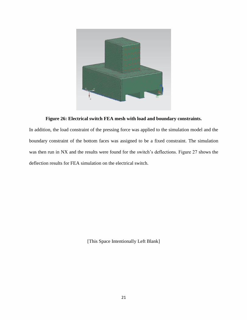
To complete the FEA simulation on the electrical switch, the NX CAD model was
imported into NX’s structural FEA simulation environment. The material of polypropylene (PP)
was assigned as the material and a tetrahedral 3D mesh was applied to the electrical switch
model which is shown in Figure 26.
21
Figure 26: Electrical switch FEA mesh with load and boundary constraints.
In addition, the load constraint of the pressing force was applied to the simulation model and the
boundary constraint of the bottom faces was assigned to be a fixed constraint. The simulation
was then run in NX and the results were found for the switch’s deflections. Figure 27 shows the
deflection results for FEA simulation on the electrical switch.
[This Space Intentionally Left Blank]
22
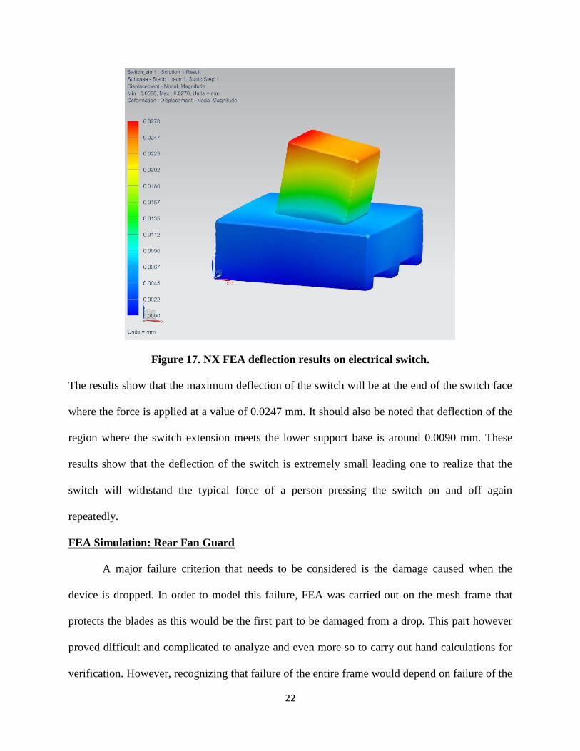
Figure 17. NX FEA deflection results on electrical switch.
The results show that the maximum deflection of the switch will be at the end of the switch face
where the force is applied at a value of 0.0247 mm. It should also be noted that deflection of the
region where the switch extension meets the lower support base is around 0.0090 mm. These
results show that the deflection of the switch is extremely small leading one to realize that the
switch will withstand the typical force of a person pressing the switch on and off again
repeatedly.
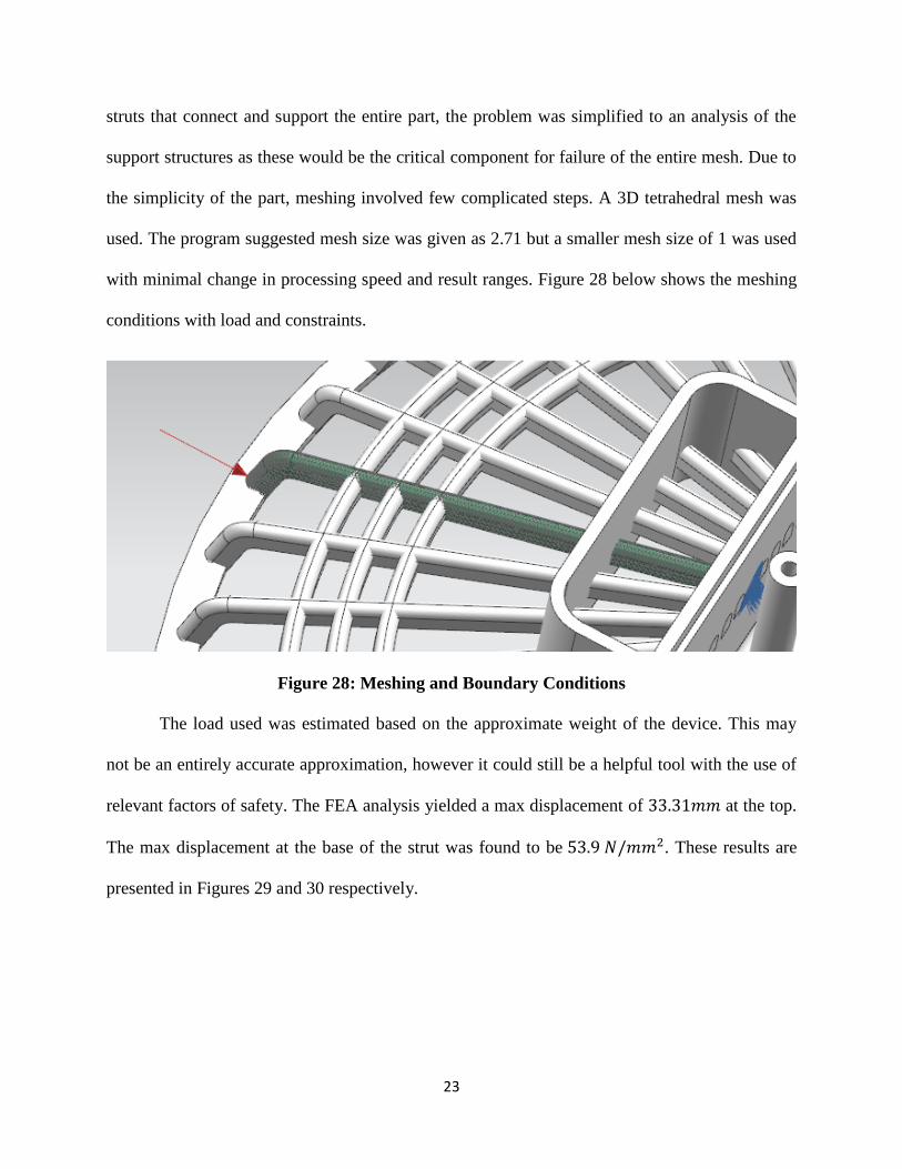
FEA Simulation: Rear Fan Guard
A major failure criterion that needs to be considered is the damage caused when the
device is dropped. In order to model this failure, FEA was carried out on the mesh frame that
protects the blades as this would be the first part to be damaged from a drop. This part however
proved difficult and complicated to analyze and even more so to carry out hand calculations for
verification. However, recognizing that failure of the entire frame would depend on failure of the
23
struts that connect and support the entire part, the problem was simplified to an analysis of the
support structures as these would be the critical component for failure of the entire mesh. Due to
the simplicity of the part, meshing involved few complicated steps. A 3D tetrahedral mesh was
used. The program suggested mesh size was given as 2.71 but a smaller mesh size of 1 was used
with minimal change in processing speed and result ranges. Figure 28 below shows the meshing
conditions with load and constraints.
Figure 28: Meshing and Boundary Conditions
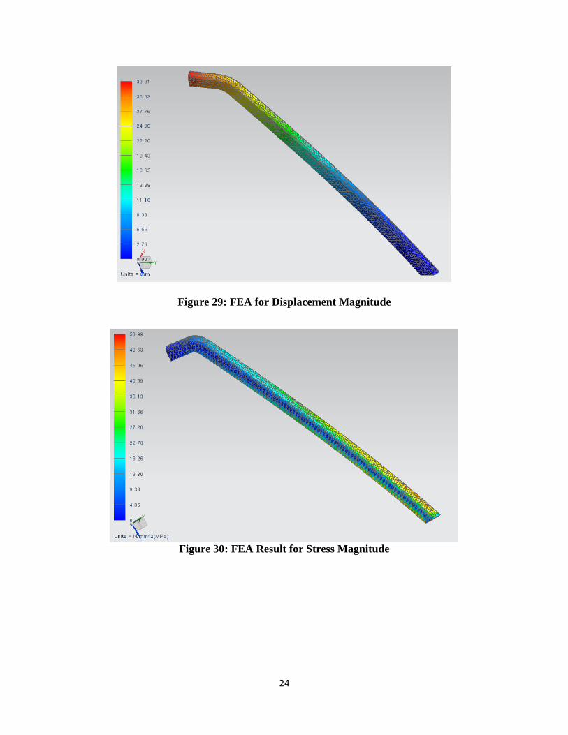
The load used was estimated based on the approximate weight of the device. This may
not be an entirely accurate approximation, however it could still be a helpful tool with the use of
relevant factors of safety. The FEA analysis yielded a max displacement of 33.31𝑚𝑚 at the top.
The max displacement at the base of the strut was found to be 53.9 𝑁/𝑚𝑚2. These results are
presented in Figures 29 and 30 respectively.
24
Figure 29: FEA for Displacement Magnitude
Figure 30: FEA Result for Stress Magnitude
25
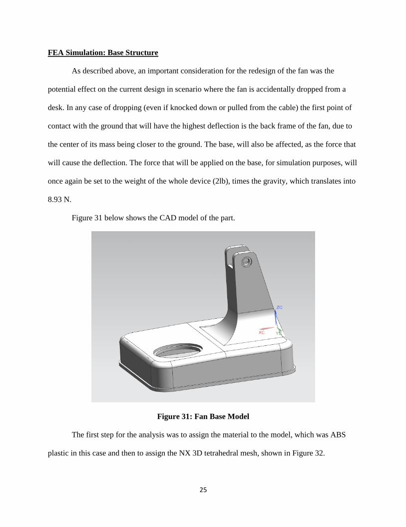
FEA Simulation: Base Structure
As described above, an important consideration for the redesign of the fan was the
potential effect on the current design in scenario where the fan is accidentally dropped from a
desk. In any case of dropping (even if knocked down or pulled from the cable) the first point of
contact with the ground that will have the highest deflection is the back frame of the fan, due to
the center of its mass being closer to the ground. The base, will also be affected, as the force that
will cause the deflection. The force that will be applied on the base, for simulation purposes, will
once again be set to the weight of the whole device (2lb), times the gravity, which translates into
8.93 N.
Figure 31 below shows the CAD model of the part.
Figure 31: Fan Base Model
The first step for the analysis was to assign the material to the model, which was ABS
plastic in this case and then to assign the NX 3D tetrahedral mesh, shown in Figure 32.
26
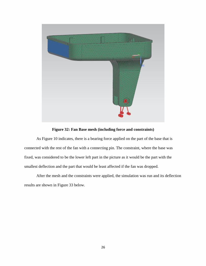
Figure 32: Fan Base mesh (including force and constraints)
As Figure 10 indicates, there is a bearing force applied on the part of the base that is
connected with the rest of the fan with a connecting pin. The constraint, where the base was
fixed, was considered to be the lower left part in the picture as it would be the part with the
smallest deflection and the part that would be least affected if the fan was dropped.
After the mesh and the constraints were applied, the simulation was run and its deflection
results are shown in Figure 33 below.
27
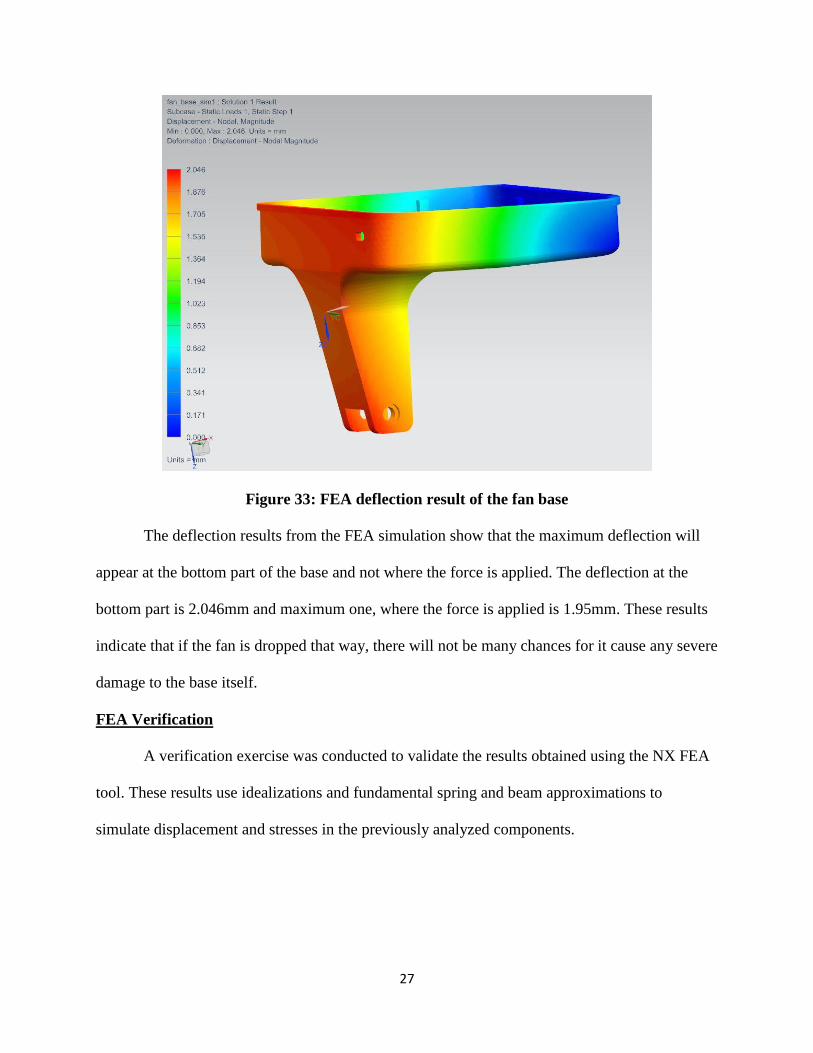
Figure 33: FEA deflection result of the fan base
The deflection results from the FEA simulation show that the maximum deflection will
appear at the bottom part of the base and not where the force is applied. The deflection at the
bottom part is 2.046mm and maximum one, where the force is applied is 1.95mm. These results
indicate that if the fan is dropped that way, there will not be many chances for it cause any severe
damage to the base itself.
FEA Verification
A verification exercise was conducted to validate the results obtained using the NX FEA
tool. These results use idealizations and fundamental spring and beam approximations to
simulate displacement and stresses in the previously analyzed components.
28
FEA Hand Calculation Verification: Electrical Switch
To verify the results obtained from NX’s FEA simulation for the electric switch, simple
hand calculations for the deflection of the switch were performed as outlined below.
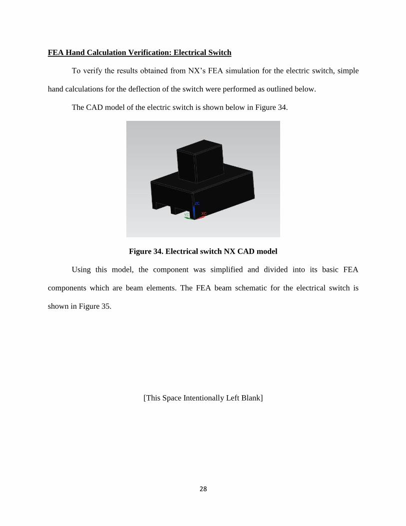
The CAD model of the electric switch is shown below in Figure 34.
Figure 34. Electrical switch NX CAD model
Using this model, the component was simplified and divided into its basic FEA
components which are beam elements. The FEA beam schematic for the electrical switch is
shown in Figure 35.
[This Space Intentionally Left Blank]
29
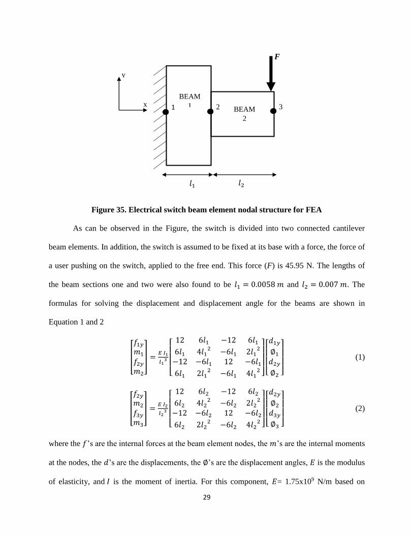
Figure 35. Electrical switch beam element nodal structure for FEA
As can be observed in the Figure, the switch is divided into two connected cantilever
beam elements. In addition, the switch is assumed to be fixed at its base with a force, the force of
a user pushing on the switch, applied to the free end. This force (F) is 45.95 N. The lengths of
the beam sections one and two were also found to be 𝑙1 = 0.0058 𝑚 and 𝑙2 = 0.007 𝑚. The
formulas for solving the displacement and displacement angle for the beams are shown in
Equation 1 and 2
[
𝑓1𝑦
𝑚1
𝑓2𝑦
𝑚2
] =𝐸 𝐼1
𝑙13
[
12 6𝑙1 −12 6𝑙16𝑙1 4𝑙1
2 −6𝑙1 2𝑙12
−12 −6𝑙1 12 −6𝑙1
6𝑙1 2𝑙12 −6𝑙1 4𝑙1
2 ]
[ 𝑑1𝑦
∅1
𝑑2𝑦
∅2 ]
(1)
[
𝑓2𝑦
𝑚2
𝑓3𝑦
𝑚3
] =𝐸 𝐼2
𝑙23
[
12 6𝑙2 −12 6𝑙26𝑙2 4𝑙2
2 −6𝑙2 2𝑙22
−12 −6𝑙2 12 −6𝑙26𝑙2 2𝑙2
2 −6𝑙2 4𝑙22 ]
[ 𝑑2𝑦
∅2
𝑑3𝑦
∅3 ]
(2)
where the 𝑓’s are the internal forces at the beam element nodes, the 𝑚’s are the internal moments
at the nodes, the 𝑑’s are the displacements, the ∅’s are the displacement angles, 𝐸 is the modulus
of elasticity, and 𝐼 is the moment of inertia. For this component, 𝐸= 1.75x10⁹ N/m based on
1 2 3
BEAM
1 BEAM
2
F
x
y
𝑙1 𝑙2
30
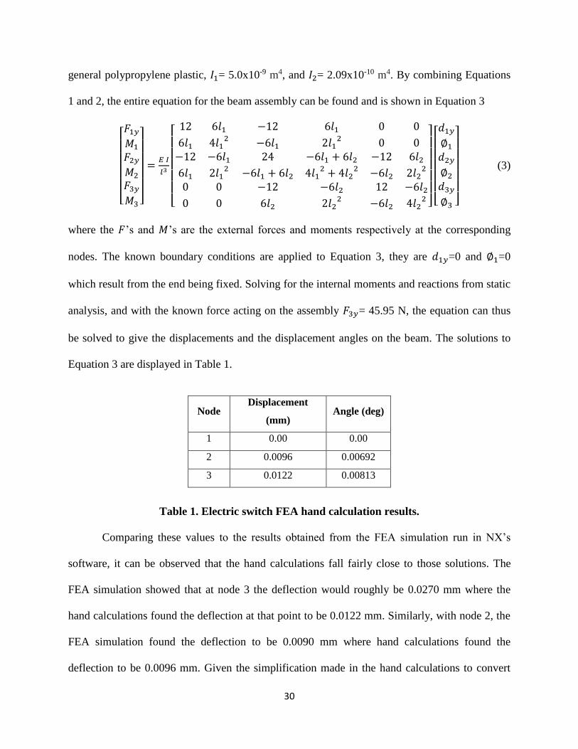
general polypropylene plastic, 𝐼1= 5.0x10⁻⁹ m4, and 𝐼2= 2.09x10⁻¹⁰ m4. By combining Equations
1 and 2, the entire equation for the beam assembly can be found and is shown in Equation 3
[ 𝐹1𝑦
𝑀1
𝐹2𝑦
𝑀2
𝐹3𝑦
𝑀3 ]
=𝐸 𝐼
𝑙3
[
12 6𝑙1 −12 6𝑙1 0 0
6𝑙1 4𝑙12 −6𝑙1 2𝑙1
2 0 0−12 −6𝑙1 24 −6𝑙1 + 6𝑙2 −12 6𝑙26𝑙1 2𝑙1
2 −6𝑙1 + 6𝑙2 4𝑙12 + 4𝑙2
2 −6𝑙2 2𝑙22
0 0 −12 −6𝑙2 12 −6𝑙20 0 6𝑙2 2𝑙2
2 −6𝑙2 4𝑙22 ]
[ 𝑑1𝑦
∅1
𝑑2𝑦
∅2
𝑑3𝑦
∅3 ]
(3)
where the 𝐹’s and 𝑀’s are the external forces and moments respectively at the corresponding
nodes. The known boundary conditions are applied to Equation 3, they are 𝑑1𝑦=0 and ∅1=0
which result from the end being fixed. Solving for the internal moments and reactions from static
analysis, and with the known force acting on the assembly 𝐹3𝑦= 45.95 N, the equation can thus
be solved to give the displacements and the displacement angles on the beam. The solutions to
Equation 3 are displayed in Table 1.
Table 1. Electric switch FEA hand calculation results.
Comparing these values to the results obtained from the FEA simulation run in NX’s
software, it can be observed that the hand calculations fall fairly close to those solutions. The
FEA simulation showed that at node 3 the deflection would roughly be 0.0270 mm where the
hand calculations found the deflection at that point to be 0.0122 mm. Similarly, with node 2, the
FEA simulation found the deflection to be 0.0090 mm where hand calculations found the
deflection to be 0.0096 mm. Given the simplification made in the hand calculations to convert
Node Displacement
(mm) Angle (deg)
1 0.00 0.00
2 0.0096 0.00692
3 0.0122 0.00813
31
the electrical switch model to nodal elements, the difference in deflections of the two methods is
reasonable. The hand calculations also show that FEA simulation model is accurately simulating
the reaction of the force on the electrical switch which means the data from it can be used for
further analysis on the part model.
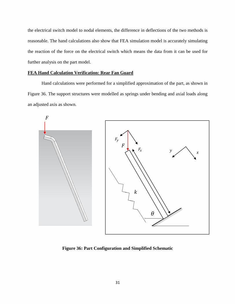
FEA Hand Calculation Verification: Rear Fan Guard
Hand calculations were performed for a simplified approximation of the part, as shown in
Figure 36. The support structures were modelled as springs under bending and axial loads along
an adjusted axis as shown.
Figure 36: Part Configuration and Simplified Schematic
𝐹𝑥
𝐹𝑦
𝜃
𝑥 𝑦
𝐹
𝑘
𝐹

32
The force component in both directions was evaluated and the magnitude calculated and
compared to the magnitude from the FEA simulation. The matrix Equations 4, 5 & 6 below were
used to estimate the displacement in both directions respectively.
𝐹𝑦 = 𝐹 sin 𝜃 ; 𝐹𝑥 = 𝐹 cos 𝜃 (4)
[
𝐹1𝑦
𝑀1
𝐹2𝑦 = −𝐹1𝑦
𝑀2 = −𝑀1 ] =
𝐸𝐼
𝐿3[
12 6𝐿 −126𝐿 4𝐿2 −6𝐿
−12 −6𝐿 12 6𝐿 2𝐿2 −6𝐿
6𝐿2𝐿2
6𝐿4𝐿2
]
[
𝑑1𝑦
𝜙1
𝑑2𝑦 = 0
𝜙2 = 0 ]
→ [𝐹1𝑦
𝑀1] =
𝐸𝐼
𝐿3[−12 6𝐿−6𝐿 2𝐿2] [
𝑑1𝑦
𝜙1] (5)
[𝐹1𝑥
𝐹2𝑥 = −𝐹1𝑥] =
𝐴𝐸
𝐿[
2 −1−1 1
] [𝑑1𝑥
𝑑2𝑥 = 0] → 𝐹1𝑥 =
𝐴𝐸
𝐿𝑑1𝑥 (6)
Where:
𝜃 ≅ 68°
𝐼 =𝑏ℎ3
12= 13.33
𝐴 ≅ 10𝑚𝑚2 ; 𝐸 ≅ 2 × 10³ 𝑁
𝑚𝑚2 ; 𝐿 ≅ 92𝑚𝑚 (7)
|𝑑1| = √𝑑1𝑥2 + 𝑑1𝑦
2 (8)
Simplifying the results, recognizing the fixed constraint boundary condition of the base,
yields Equations 5 and 6. The assumption of no displacement at 𝑑1𝑥 and 𝑑1𝑦 is a result of the
fixed constraint applied to the base. As a result of this assumption, the matrix can be simplified
and reduced down to the form shown in Equation 2.which can readily be solved to give a
displacement magnitude of 37.35𝑚𝑚 which compares reasonably well with the FEA
displacement of 33.31𝑚𝑚
Another critical component to be measured is the reaction force at the base. Specifically,
the maximum principal stress. This stress could lead to a tensile failure at the base. Values were
obtained using the FEA analysis for a force of 8.3N to be 53.9 𝑁/𝑚𝑚2. To evaluate this result, a
33
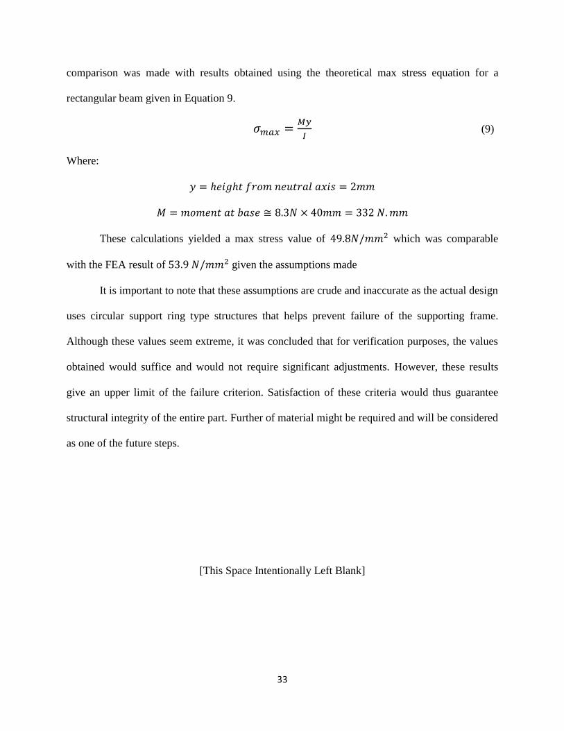
comparison was made with results obtained using the theoretical max stress equation for a
rectangular beam given in Equation 9.
𝜎𝑚𝑎𝑥 =𝑀𝑦
𝐼 (9)
Where:
𝑦 = ℎ𝑒𝑖𝑔ℎ𝑡 𝑓𝑟𝑜𝑚 𝑛𝑒𝑢𝑡𝑟𝑎𝑙 𝑎𝑥𝑖𝑠 = 2𝑚𝑚
𝑀 = 𝑚𝑜𝑚𝑒𝑛𝑡 𝑎𝑡 𝑏𝑎𝑠𝑒 ≅ 8.3𝑁 × 40𝑚𝑚 = 332 𝑁.𝑚𝑚
These calculations yielded a max stress value of 49.8𝑁/𝑚𝑚2 which was comparable
with the FEA result of 53.9 𝑁/𝑚𝑚2 given the assumptions made
It is important to note that these assumptions are crude and inaccurate as the actual design
uses circular support ring type structures that helps prevent failure of the supporting frame.
Although these values seem extreme, it was concluded that for verification purposes, the values
obtained would suffice and would not require significant adjustments. However, these results
give an upper limit of the failure criterion. Satisfaction of these criteria would thus guarantee
structural integrity of the entire part. Further of material might be required and will be considered
as one of the future steps.
[This Space Intentionally Left Blank]
34
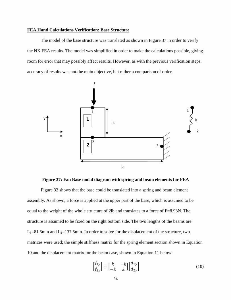
FEA Hand Calculations Verification: Base Structure
The model of the base structure was translated as shown in Figure 37 in order to verify
the NX FEA results. The model was simplified in order to make the calculations possible, giving
room for error that may possibly affect results. However, as with the previous verification steps,
accuracy of results was not the main objective, but rather a comparison of order.
Figure 37: Fan Base nodal diagram with spring and beam elements for FEA
Figure 32 shows that the base could be translated into a spring and beam element
assembly. As shown, a force is applied at the upper part of the base, which is assumed to be
equal to the weight of the whole structure of 2lb and translates to a force of F=8.93N. The
structure is assumed to be fixed on the right bottom side. The two lengths of the beams are
L1=81.5mm and L2=137.5mm. In order to solve for the displacement of the structure, two
matrices were used; the simple stiffness matrix for the spring element section shown in Equation
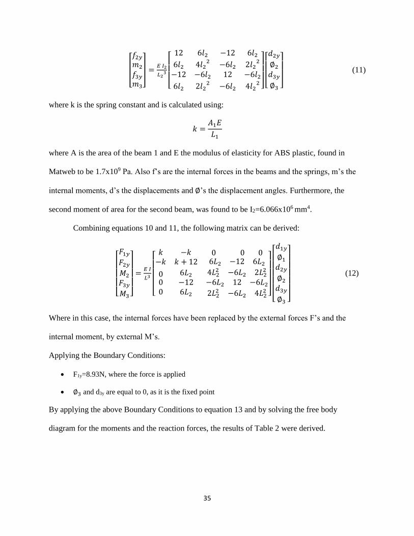
10 and the displacement matrix for the beam case, shown in Equation 11 below:
[𝑓1𝑦
𝑓2𝑦] = [
𝑘 −𝑘−𝑘 𝑘
] [𝑑1𝑦
𝑑2𝑦] (10)
2
k
1 1
2 3
x
y L1
L2
F
35
[
𝑓2𝑦
𝑚2
𝑓3𝑦
𝑚3
] =𝐸 𝐼2
𝐿23
[
12 6𝑙2 −12 6𝑙26𝑙2 4𝑙2
2 −6𝑙2 2𝑙22
−12 −6𝑙2 12 −6𝑙26𝑙2 2𝑙2
2 −6𝑙2 4𝑙22 ]
[ 𝑑2𝑦
∅2
𝑑3𝑦
∅3 ]
(11)
where k is the spring constant and is calculated using:
𝑘 =𝐴1𝐸
𝐿1
where A is the area of the beam 1 and E the modulus of elasticity for ABS plastic, found in
Matweb to be 1.7x10⁹ Pa. Also f’s are the internal forces in the beams and the springs, m’s the
internal moments, d’s the displacements and ∅’s the displacement angles. Furthermore, the
second moment of area for the second beam, was found to be I2=6.066x106 mm4.
Combining equations 10 and 11, the following matrix can be derived:
[ 𝐹1𝑦
𝐹2𝑦
𝑀2
𝐹3𝑦
𝑀3 ]
=𝐸 𝐼
𝐿3
[
𝑘 −𝑘 0 0 0−𝑘 𝑘 + 12 6𝐿2 −12 6𝐿2
000
6𝐿2
−126𝐿2
4𝐿22 −6𝐿2 2𝐿2
2
−6𝐿2 12 −6𝐿2
2𝐿22 −6𝐿2 4𝐿2
2 ]
[ 𝑑1𝑦
∅1
𝑑2𝑦
∅2
𝑑3𝑦
∅3 ]
(12)
Where in this case, the internal forces have been replaced by the external forces F’s and the
internal moment, by external M’s.
Applying the Boundary Conditions:
F1y=8.93N, where the force is applied
∅3 and d3y are equal to 0, as it is the fixed point
By applying the above Boundary Conditions to equation 13 and by solving the free body
diagram for the moments and the reaction forces, the results of Table 2 were derived.
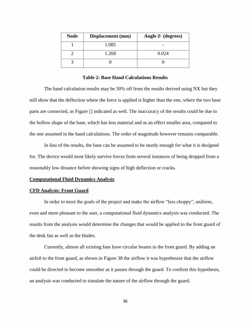
36
Table 2: Base Hand Calculations Results
The hand calculation results may be 50% off from the results derived using NX but they
still show that the deflection where the force is applied is higher than the one, where the two base
parts are connected, as Figure [] indicated as well. The inaccuracy of the results could be due to
the hollow shape of the base, which has less material and as an effect smaller area, compared to
the one assumed in the hand calculations. The order of magnitude however remains comparable.
In lieu of the results, the base can be assumed to be sturdy enough for what it is designed
for. The device would most likely survive forces from several instances of being dropped from a
reasonably low distance before showing signs of high deflection or cracks.
Computational Fluid Dynamics Analysis
CFD Analysis: Front Guard
In order to meet the goals of the project and make the airflow “less choppy”, uniform,
even and more pleasant to the user, a computational fluid dynamics analysis was conducted. The
results from the analysis would determine the changes that would be applied to the front guard of
the desk fan as well as the blades.
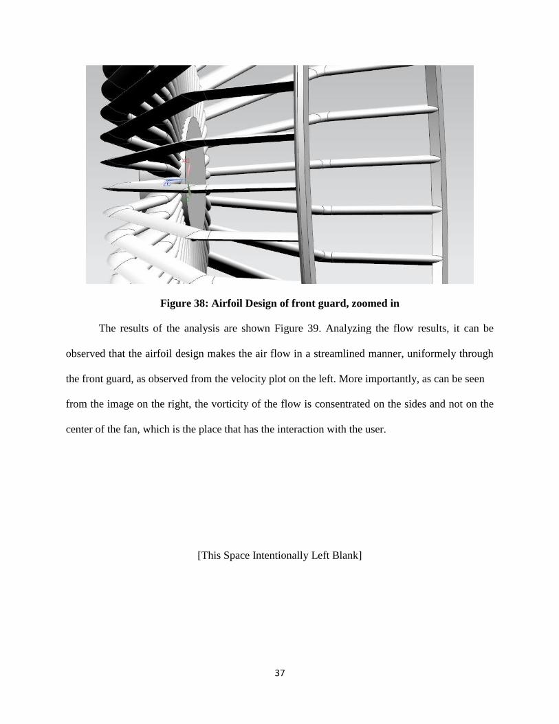
Currently, almost all existing fans have circular beams in the front guard. By adding an
airfoil to the front guard, as shown in Figure 38 the airflow it was hypothesize that the airflow
could be directed to become smoother as it passes through the guard. To confirm this hypothesis,
an analysis was conducted to simulate the nature of the airflow through the guard.
Node Displacement (mm) Angle ∅ (degrees)
1 1.085 -
2 1.268 0.024
3 0 0
37
Figure 38: Airfoil Design of front guard, zoomed in
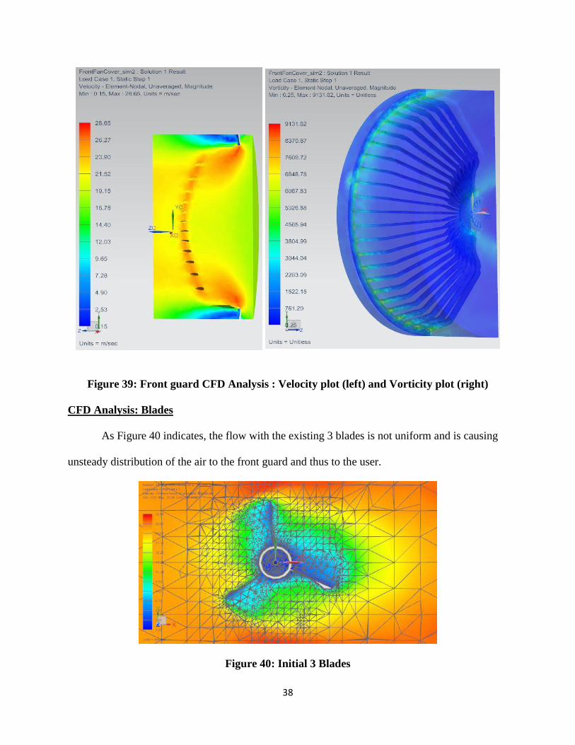
The results of the analysis are shown Figure 39. Analyzing the flow results, it can be
observed that the airfoil design makes the air flow in a streamlined manner, uniformely through
the front guard, as observed from the velocity plot on the left. More importantly, as can be seen
from the image on the right, the vorticity of the flow is consentrated on the sides and not on the
center of the fan, which is the place that has the interaction with the user.
[This Space Intentionally Left Blank]
38
Figure 39: Front guard CFD Analysis : Velocity plot (left) and Vorticity plot (right)
CFD Analysis: Blades
As Figure 40 indicates, the flow with the existing 3 blades is not uniform and is causing
unsteady distribution of the air to the front guard and thus to the user.
Figure 40: Initial 3 Blades
39
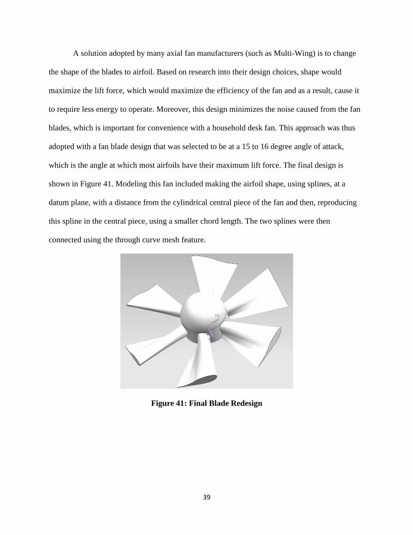
A solution adopted by many axial fan manufacturers (such as Multi-Wing) is to change
the shape of the blades to airfoil. Based on research into their design choices, shape would
maximize the lift force, which would maximize the efficiency of the fan and as a result, cause it
to require less energy to operate. Moreover, this design minimizes the noise caused from the fan
blades, which is important for convenience with a household desk fan. This approach was thus
adopted with a fan blade design that was selected to be at a 15 to 16 degree angle of attack,
which is the angle at which most airfoils have their maximum lift force. The final design is
shown in Figure 41. Modeling this fan included making the airfoil shape, using splines, at a
datum plane, with a distance from the cylindrical central piece of the fan and then, reproducing
this spline in the central piece, using a smaller chord length. The two splines were then
connected using the through curve mesh feature.
Figure 41: Final Blade Redesign
40
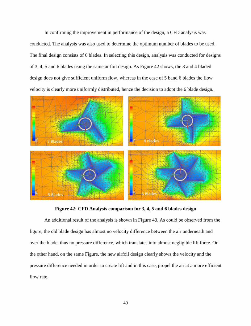
In confirming the improvement in performance of the design, a CFD analysis was
conducted. The analysis was also used to determine the optimum number of blades to be used.
The final design consists of 6 blades. In selecting this design, analysis was conducted for designs
of 3, 4, 5 and 6 blades using the same airfoil design. As Figure 42 shows, the 3 and 4 bladed
design does not give sufficient uniform flow, whereas in the case of 5 band 6 blades the flow
velocity is clearly more uniformly distributed, hence the decision to adopt the 6 blade design.
Figure 42: CFD Analysis comparison for 3, 4, 5 and 6 blades design
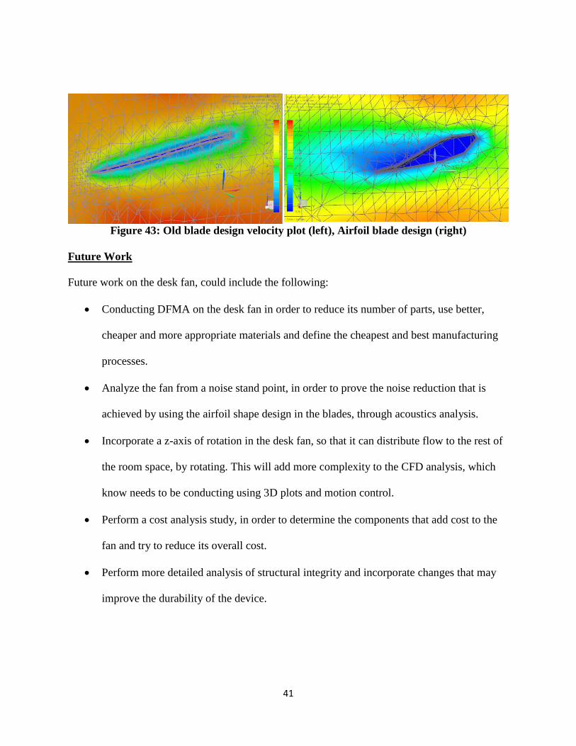
An additional result of the analysis is shown in Figure 43. As could be observed from the
figure, the old blade design has almost no velocity difference between the air underneath and
over the blade, thus no pressure difference, which translates into almost negligible lift force. On
the other hand, on the same Figure, the new airfoil design clearly shows the velocity and the
pressure difference needed in order to create lift and in this case, propel the air at a more efficient
flow rate.
41
Figure 43: Old blade design velocity plot (left), Airfoil blade design (right)
Future Work
Future work on the desk fan, could include the following:
Conducting DFMA on the desk fan in order to reduce its number of parts, use better,
cheaper and more appropriate materials and define the cheapest and best manufacturing
processes.
Analyze the fan from a noise stand point, in order to prove the noise reduction that is
achieved by using the airfoil shape design in the blades, through acoustics analysis.
Incorporate a z-axis of rotation in the desk fan, so that it can distribute flow to the rest of
the room space, by rotating. This will add more complexity to the CFD analysis, which
know needs to be conducting using 3D plots and motion control.
Perform a cost analysis study, in order to determine the components that add cost to the
fan and try to reduce its overall cost.
Perform more detailed analysis of structural integrity and incorporate changes that may
improve the durability of the device.
42
SUMMARY AND FINAL ASSEMBLY
The aim of this project was to redesign a common desk fan, in order to reduce the
unsteady and distorted air flow created from it that is irritating to the user.A basic desk fan model
was designed. The fan was disassembled and all of its components were accurately measured
using rulers and calipers for higher accuracy. Then the parts were all assembled together.
FEA was conducted on critical components, such as the switch, which would be turned
on and off frequently using the NX FEA tool. Also a crash test was considered, in case the fan
was dropped from the table that it was placed, and two parts of the fan were pointed to be the
most critical and FEA was applied (rear guard and base). These results were confirmed by a hand
calculation verification exercise.
Finally, a CFD Analysis was used in order to meet the aims of the project and ensure that
the desired goals were reached. During this analysis the frond guard and the blades were
redesigned, using airfoil shape.
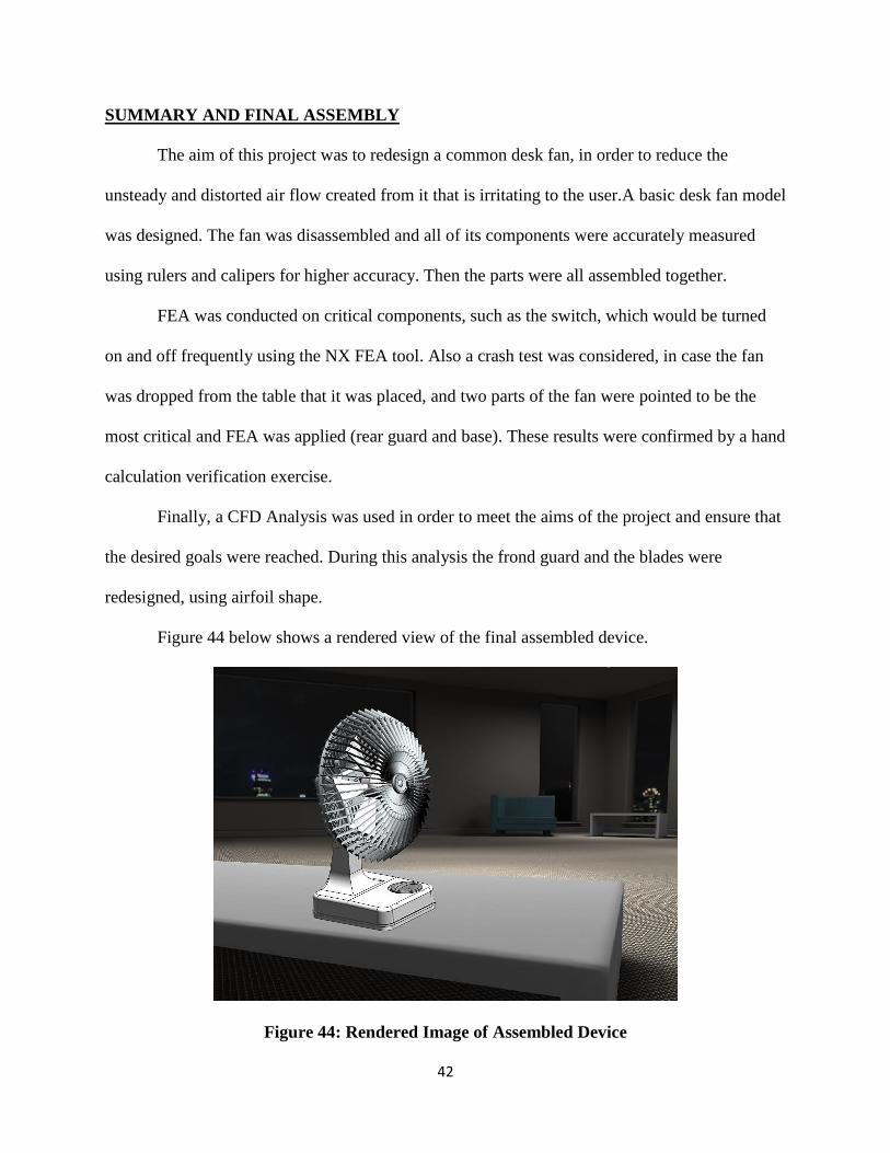
Figure 44 below shows a rendered view of the final assembled device.
Figure 44: Rendered Image of Assembled Device
3 Blades 5 Blades 4 Blades 6 Blades