Embed Size (px)
Citation preview
Designs of Boiler Burner Management System
By
Ahmed Mohamed Said Abou El Rish
FINAL PROJECT REPORT
Submitted to the Department of Electrical & Electronic Engineering
in Partial Fulfillment of the Requirements
for the Degree
Bachelor of Engineering (Hons)
(Electrical & Electronic Engineering)
Universiti Teknologi PETRONAS
Bandar Seri Iskandar
31750 Tronoh
Perak Darul Ridzuan
Copyright 2013
by
Ahmed Mohamed Said Abou El Rish, 2013
i
CERTIFICATION OF APPROVAL
Designs of Boiler Burner Management System
By
Ahmed Mohamed Said Abou El Rish
A project dissertation submitted to the
Electrical & Electronics Engineering Programme
Universiti Teknologi PETRONAS
in partial Fulfilment of the requirement for the
BACHELOR OF ENGINEERING (Hons)
(ELECTRICAL & ELECTRONICS ENGINEERING)
Approved by,
_____________________
Dr. Irraivan Elamvazuthi
Project Supervisor
UNIVERSITI TEKNOLOGI PETRONAS
TRONOH, PERAK
May 2013

ii
CERTIFICATION OF ORIGINALITY
This is to certify that I am responsible for the work submitted in this project, that the original
work is my own except as specified in the references and acknowledgements, and that the
original work contained herein have not been undertaken or done by unspecified sources or
persons.
______________________________________
Ahmed Mohamed Said Abou El Rish
iii
ABSTRACT
Boilers are used in many industrial facilities to generate electricity or produce heat, steam
and hot water. Many hazards are occurring on the boiler affecting boiler operation. Within
unsafe conditions, boiler hazards might cause explosions, property implosions, injuries and
death. This project outlines changes on piping and instrumentation diagram (P&ID controller) of
boiler pipelines improving smooth operation and boiler efficiency following control
requirements of international standards and safety regulations such as National Fire Protection
Association (NFPA) and American Society of Mechanical Engineers (ASME) to be checked on
Boiler Burner Management System and all safety requirements to be developed. Moreover, the
project presents the safe arrangement of boiler components in P&ID designs for each part of the
boiler to achieve functional safety requirements and comply with the original approach for
Burner Management Systems.
iv
Table of Contents
ABSTRACT ............................................................................................................................. iii
List of Tables .......................................................................................................................... vii
List of Figures ........................................................................................................................ viii
CHAPTER 1 ............................................................................................................................... 1
INTRODUCTION ...................................................................................................................... 1
1.1 Boiler Mechanis. .......................................................................................................... 1
1.1.1) Boiler……………………………………………………………………………..1
1.1.2) Burner Management System (BMS)……………………………………………..2
1.1.3) NFPA Code………………………………………………………………………3
1.2 Problem Statement ....................................................................................................... 3
1.3 Objectives ..................................................................................................................... 5
1.4 Scope of study .............................................................................................................. 5
CHAPTER 2 ............................................................................................................................... 6
LITERATURE REVIEW .......................................................................................................... 6
2.1 P&ID Designing .......................................................................................................... 6
2.2 Boiler Control .............................................................................................................. 7
CHAPTER 3 ............................................................................................................................. 11
METHODOLOGY .................................................................................................................... 11
3.1 Research Methodology .............................................................................................. 11
3.1.1 Reviewing current P&ID designs……………………………………………….11
3.1.2 Laboratory Designs……………………………………………………………..11
3.1.3 Comparing field data…………………………………………………………...12
3.2 Resources ................................................................................................................... 12
3.3 Work Schedule ........................................................................................................... 13
v
3.4 Flowchart ................................................................................................................... 14
CHAPTER 4: ............................................................................................................................ 15
Discussion & Results ............................................................................................................ 15
4.1 Control........................................................................................................................ 15
4.1.1 Pressure Control………………………………………………………………..15
4.1.2 Flow Control……………………………………………………………………20
4.2 Safety .......................................................................................................................... 23
4.2.1 Boiler Burners:………………………………………………………………….23
4.3 Cost ............................................................................................................................. 27
4.3.1 Oil and Atomizing Media Skid………………………………………………….27
4.4 Efficiency. .................................................................................................................. 29
4.4.1 Heat Losses with higher heating value (HHV)…………………………………29
4.4.2 Efficiency with lower heating value (LHV)…………………………………….32
CHAPTER 5: ............................................................................................................................ 33
Conclusion ............................................................................................................................. 33
Recommendations ............................................................................................................... 34
Industrial Recommendations…………………………………………………………….34
Academic Recommendations……………………………………………………………34
References ............................................................................................................................. 35
Appendices .............................................................................................................................. 37
Appendix-I ........................................................................................................................... 37
Results …………………………………………………………………………………..37
Appendix-II .......................................................................................................................... 44
Glossary………………………………………………………………………………….44
Appendix-III ........................................................................................................................ 47
vi
ISA Control Diagramming System………………………………………………………47
Appendix-IV ......................................................................................................................... 50
Glossary of Common Boiler Terms……………………………………………………...50
Appendix-IV ......................................................................................................................... 52
Standards………………………………………………………………………………...52
Appendix-V .......................................................................................................................... 63
Awards …………………………………………………………………………………..63
vii
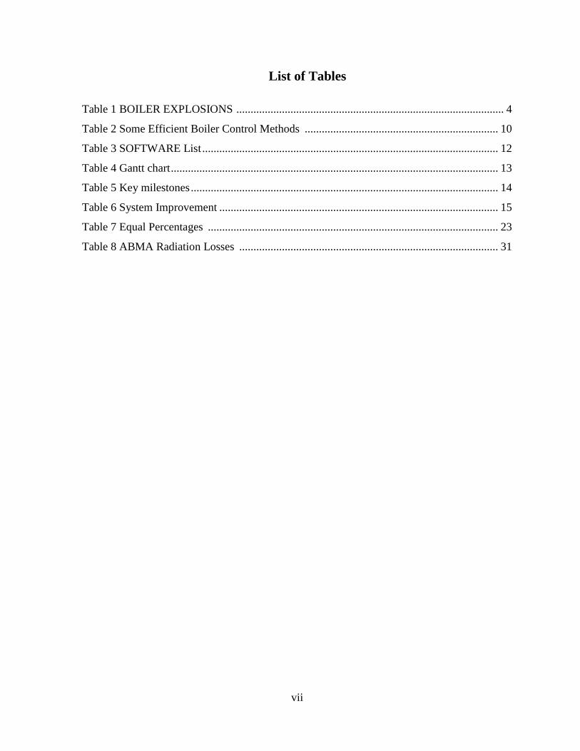
List of Tables
Table 1 BOILER EXPLOSIONS .............................................................................................. 4
Table 2 Some Efficient Boiler Control Methods .................................................................... 10
Table 3 SOFTWARE List ........................................................................................................ 12
Table 4 Gantt chart ................................................................................................................... 13
Table 5 Key milestones ............................................................................................................ 14
Table 6 System Improvement .................................................................................................. 15
Table 7 Equal Percentages ...................................................................................................... 23
Table 8 ABMA Radiation Losses ........................................................................................... 31
viii
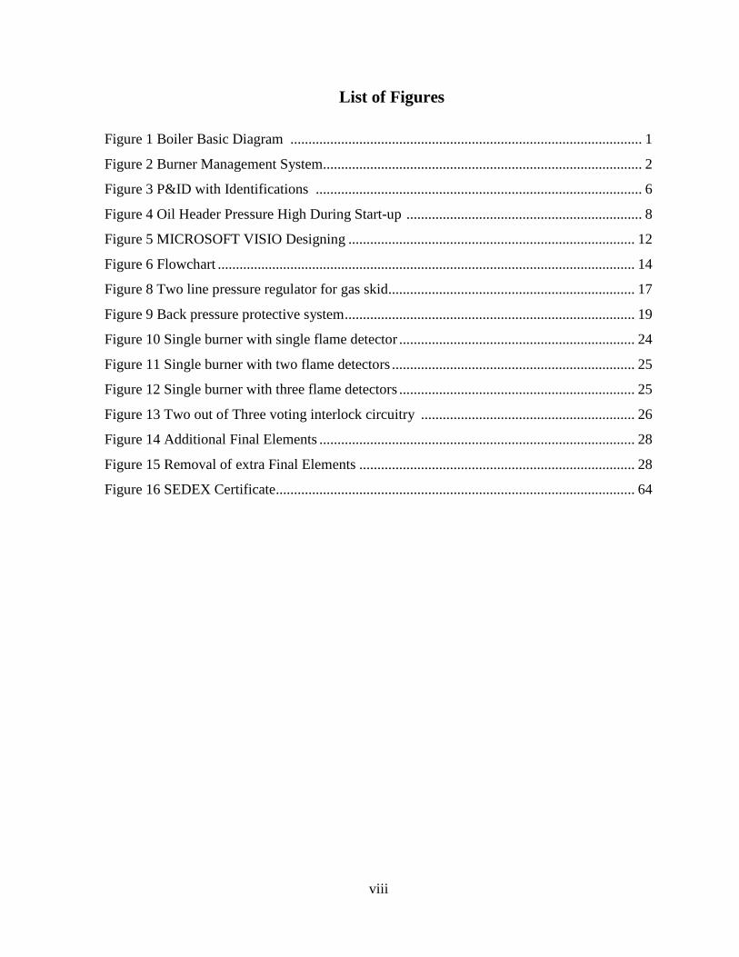
List of Figures
Figure 1 Boiler Basic Diagram ................................................................................................. 1
Figure 2 Burner Management System........................................................................................ 2
Figure 3 P&ID with Identifications .......................................................................................... 6
Figure 4 Oil Header Pressure High During Start-up ................................................................. 8
Figure 5 MICROSOFT VISIO Designing ............................................................................... 12
Figure 6 Flowchart ................................................................................................................... 14
Figure 8 Two line pressure regulator for gas skid.................................................................... 17
Figure 9 Back pressure protective system ................................................................................ 19
Figure 10 Single burner with single flame detector ................................................................. 24
Figure 11 Single burner with two flame detectors ................................................................... 25
Figure 12 Single burner with three flame detectors ................................................................. 25
Figure 13 Two out of Three voting interlock circuitry ........................................................... 26
Figure 14 Additional Final Elements ....................................................................................... 28
Figure 15 Removal of extra Final Elements ............................................................................ 28
Figure 16 SEDEX Certificate................................................................................................... 64
1
CHAPTER 1 INTRODUCTION
1.1 Boiler Mechanism.
1.1.1) Boiler:
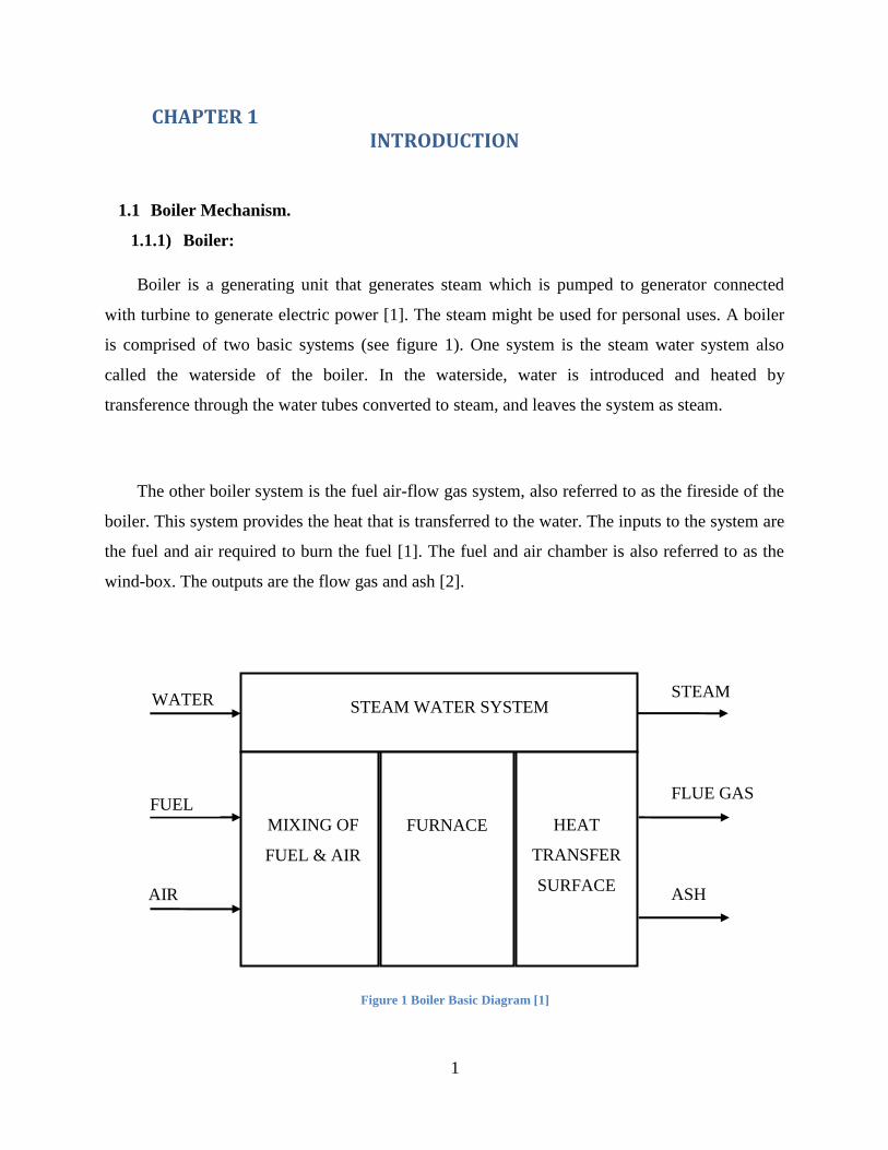
Boiler is a generating unit that generates steam which is pumped to generator connected
with turbine to generate electric power [1]. The steam might be used for personal uses. A boiler
is comprised of two basic systems (see figure 1). One system is the steam water system also
called the waterside of the boiler. In the waterside, water is introduced and heated by
transference through the water tubes converted to steam, and leaves the system as steam.
The other boiler system is the fuel air-flow gas system, also referred to as the fireside of the
boiler. This system provides the heat that is transferred to the water. The inputs to the system are
the fuel and air required to burn the fuel [1]. The fuel and air chamber is also referred to as the
wind-box. The outputs are the flow gas and ash [2].
Figure 1 Boiler Basic Diagram [1]
STEAM WATER SYSTEM
MIXING OF
FUEL & AIR
FURNACE
HEAT
TRANSFER
SURFACE
WATER
FUEL
AIR
STEAM
FLUE GAS
ASH
2
1.1.2) Burner Management System (BMS):
The general term used for a safety system is burner management system (BMS). However, it
may also be referred to as a combustion safeguard, burner/boiler safety system, burner control
system, flame safeguard system, safety shutdown system, furnace safeguard supervisory system,
emergency shutdown system or a safety instrumented system (SIS) [3].
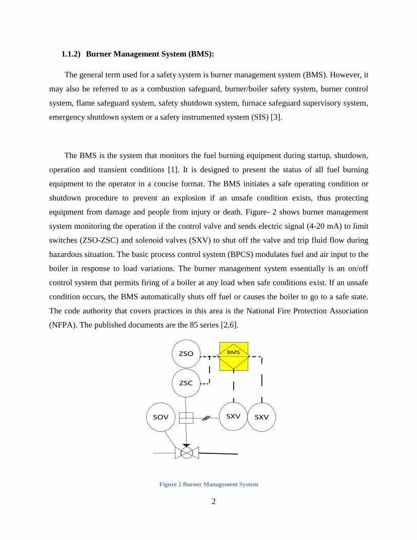
The BMS is the system that monitors the fuel burning equipment during startup, shutdown,
operation and transient conditions [1]. It is designed to present the status of all fuel burning
equipment to the operator in a concise format. The BMS initiates a safe operating condition or
shutdown procedure to prevent an explosion if an unsafe condition exists, thus protecting
equipment from damage and people from injury or death. Figure- 2 shows burner management
system monitoring the operation if the control valve and sends electric signal (4-20 mA) to limit
switches (ZSO-ZSC) and solenoid valves (SXV) to shut off the valve and trip fluid flow during
hazardous situation. The basic process control system (BPCS) modulates fuel and air input to the
boiler in response to load variations. The burner management system essentially is an on/off
control system that permits firing of a boiler at any load when safe conditions exist. If an unsafe
condition occurs, the BMS automatically shuts off fuel or causes the boiler to go to a safe state.
The code authority that covers practices in this area is the National Fire Protection Association
(NFPA). The published documents are the 85 series [2,6].
SOV
ZSC
ZSO BMS
SXV SXV
Figure 2 Burner Management System

3
1.1.3) NFPA Code:
The NFPA 85 is a Boiler and Combustion Systems Hazards Code 2011 Edition [6]. The
NFPA 85 Code applies to single burner boilers; multiple burner boilers; stokers; atmospheric
fluidized-bed boilers with a fuel input rating of 3.7 MW (12.5 million Btu/hr) or greater;
pulverized fuel systems; and fired or unfired steam generators used to recover heat from
combustion turbines (heat recovery steam generators, HRSG) [2,6].
The purpose of the Code is to ensure safe operation and to prevent uncontrolled fires,
explosions, and implosions in equipment. The Code establishes minimum requirements for the
design, installation, operation, training, and maintenance of boilers, pulverized fuel systems,
HRSGs, and their systems for fuel burning, air supply and combustion products removal. The
Code requires the coordination of operating procedures, control systems, interlocks, and
structural design [3]. The most common contributor to boiler explosions is human error. Some
hazards are very dangerous and might cause explosions or loss of life and a master fuel trip
(MFT) is required to trip the fuel and close all fuel valves [6].
1.2 Problem Statement
Boiler Hazards:
Boiler operation and steam production has many hazardous situations and many risks affect
safety requirements. Some of those hazards might cause boiler explosions that lead to injuries,
life and property loss.
Boiler explosions typically occur during the period of lighting off the boiler. The absence of
safety components and control elements such as flame detectors, pressure regulators and flow
controllers would increase the probability of having boiler explosions and implosions. Moreover,
the arrangement of boiler components has a great effect on the stability of the operation. The
main cause of boiler explosions is the improper arrangement of boiler components such as
4
control valves, pressure gauge, shut off valves … etc. which might cause failure to trip the fuel
during any hazardous situation.
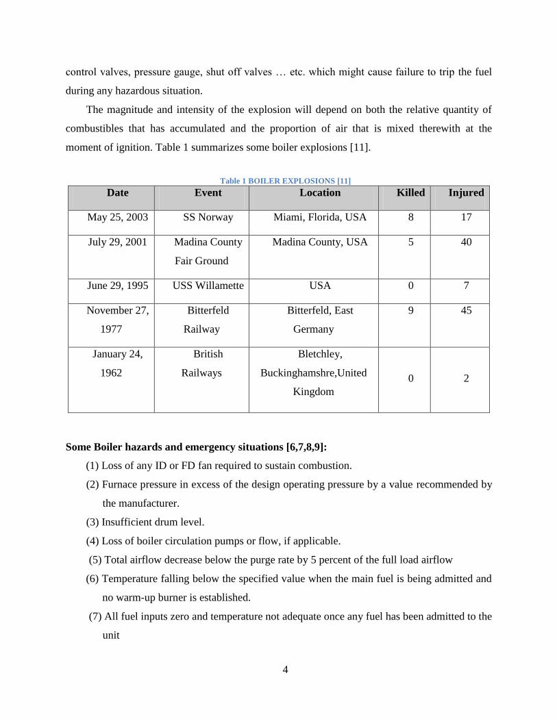
The magnitude and intensity of the explosion will depend on both the relative quantity of
combustibles that has accumulated and the proportion of air that is mixed therewith at the
moment of ignition. Table 1 summarizes some boiler explosions [11].
Table 1 BOILER EXPLOSIONS [11]
Date Event Location Killed Injured
May 25, 2003 SS Norway Miami, Florida, USA 8 17
July 29, 2001 Madina County
Fair Ground
Madina County, USA 5 40
June 29, 1995 USS Willamette USA 0 7
November 27,
1977
Bitterfeld
Railway
Bitterfeld, East
Germany
9 45
January 24,
1962
British
Railways
Bletchley,
Buckinghamshre,United
Kingdom
0
2
Some Boiler hazards and emergency situations [6,7,8,9]:
(1) Loss of any ID or FD fan required to sustain combustion.
(2) Furnace pressure in excess of the design operating pressure by a value recommended by
the manufacturer.
(3) Insufficient drum level.
(4) Loss of boiler circulation pumps or flow, if applicable.
(5) Total airflow decrease below the purge rate by 5 percent of the full load airflow
(6) Temperature falling below the specified value when the main fuel is being admitted and
no warm-up burner is established.
(7) All fuel inputs zero and temperature not adequate once any fuel has been admitted to the
unit
5
To combat the boiler explosion hazard, a proper arrangement of boiler components was
developed by creating perfect P&ID designs for boiler burner management system to reduce the
hazard to a minimum [2]. These designs also describe the boiler operation, light off and shut
down additional burners as necessary and trip the fuel whenever the continued operation appears
to be unsafe [6]. The code authority that covers practices in this area is the National Fire
Protection Association. The published documents are the 85 series. Any action to design or
modify the design of boiler safety protection circuits should include adherence to these guides
[3].
1.3 Objectives
The objective of the project is to combat the boiler explosion hazard by editing and
improving the P&ID controllers of the boiler system with a proper arrangement of boiler
components to reduce the hazard to a minimum by creating accurate piping and instrumentation
diagram (P&ID controller designs) for boiler burner management system [2]. The new P&IDs
provide a safe instrumented system to protect possible hazardous conditions such as; supervising
safety limits and flame presence during operation and insuring a complete pre-purge of boiler. It
verifies the requirements of NFPA 85 to be checked on Boiler Burner Management System and
all safety requirements were developed.
1.4 Scope of study
• Reviewing previous studies on making and editing P&ID controller.
• Reviewing non-efficient parts of the current designs.
• Designing new P&ID controller designs for the boiler.
• Testing new designs
• Establishing boiler efficiency calculations.
6
CHAPTER 2: LITERATURE REVIEW
2.1 P&ID Designing:
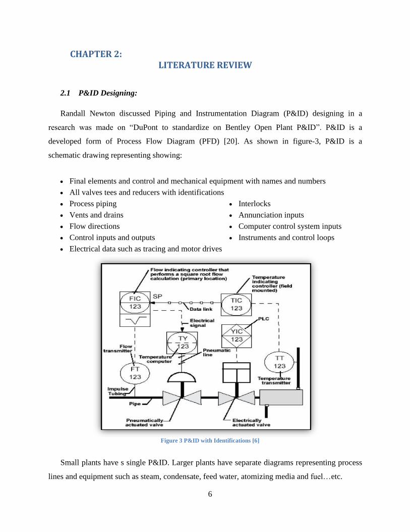
Randall Newton discussed Piping and Instrumentation Diagram (P&ID) designing in a
research was made on “DuPont to standardize on Bentley Open Plant P&ID”. P&ID is a
developed form of Process Flow Diagram (PFD) [20]. As shown in figure-3, P&ID is a
schematic drawing representing showing:
Final elements and control and mechanical equipment with names and numbers
All valves tees and reducers with identifications
Process piping
Vents and drains
Flow directions
Control inputs and outputs
Interlocks
Annunciation inputs
Computer control system inputs
Instruments and control loops
Electrical data such as tracing and motor drives
Figure 3 P&ID with Identifications [6]
Small plants have s single P&ID. Larger plants have separate diagrams representing process
lines and equipment such as steam, condensate, feed water, atomizing media and fuel…etc.
7
2.2 Boiler Control:
Peterschmidt and Taylor proposed “Boilers and Boiler Control Systems” which is based on
control methods that affect boiler operation and efficiency calculations [4]. As there are several
methods that affect boiler start-up, shutdown and flow parameters such as pressure, temperature
and flow volume [1].
“Steam explosions in boiler ash hoppers” is another study outlines steam hazards in steam
boilers and the proper control methods that help to avoid steam explosions [5]. The main cause
of steam explosions is ash leakage [3].
In another study, the fire protection systems are essential for industrial facilities using
insulation materials designed with passive fire protection systems which can avoid fires, injures
and save life and property [7].
Dukelow explained boiler mechanism, boiler control methods such as start-up, purging and
shut down and boiler automatic control (BAC) in his book “The Control of Boilers” [1]. The
book outlines the proper methods for boiler installation, testing and maintenance. Boiler hazards
cannot be avoided but minimized to operate the boiler in a safe way [1,6].
The emphasis will be on high pressure (above 15 psi) steam boilers. This study is
concentrated on the aspects of boiler control such as startup, shutdown, flame monitoring and
safety interlock system aspects [1].
Boiler control was improved by performing the modulating actions of the control using
analog equipment. The start-up, shutdown procedures and safety interlock system could are
controlled in a digital way. The development of microprocessor-based distributed digital control
has improved the control methods and equipment by integrating both two boiler control
functions into one digital control system [1,6]. Most of industrial fields now are using new
control methods with digital control systems.
Abouelrish and Soetjahjo proposed “NFPA 85 compliances of BMS” which states several
solutions for some boiler hazards affecting boiler operation and operator safety. By following
8
those methods, boiler could be controller within any hazardous condition and supplies
continuous amount of steam with the lowest cost of boiler inputs. Some of those control methods
shown below:
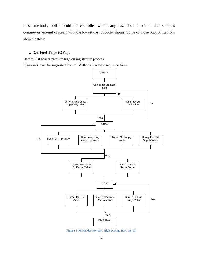
1- Oil Fuel Trips (OFT):
Hazard: Oil header pressure high during start up process
Figure-4 shows the suggested Control Methods in a logic sequence form:
Start Up
Oil header pressure
high
De- energise oil fuel
trip (OFT) relay
OFT first out
indication
Close
Boiler atomizing
media trip valve
Diesel Oil Supply
Valve
Boiler Oil Trip Valve
Heavy Fuel Oil
Supply Valve
Open Heavy Fuel
Oil Recirc Valve
Open Boiler Oil
Recirc Valve
Close
Burner Atomizing
Media valve
Burner Oil Gun
Purge Valve
Burner Oil Trip
Valve
BMS Alarm
No
Yes
Yes
No
Yes
No
Figure 4 Oil Header Pressure High During Start-up [12]
9
2- Master Fuel Trips (MFT):
Hazard: Loss of all flame
Suggested Control Methods:
1) De-energise MFT relay.
2) MFT first out indication.
3) De-energise oil fuel trip (OFT) relay.
4) OFT first out indication.
5) Close boiler oil trip valve.
6) Close Boiler atomising media trip valve.
7) Close diesel oil supply valve.
8) Close heavy fuel oil supply valve.
9) Open heavy fuel oil recirc valve.
10) Open boiler oil recirc valve.
11) De-energise gas fuel trip (GFT) relay.
12) GFT first out indication.
13) Close supply gas trip valve.
14) Open supply gas vent valve.
15) Close boiler gas trip valve.
16) Open boiler gas vent valve.
17) Close burner oil trip valve.
18) Close burner atomising media valve.
19) Close burner oil gun purge valve.
20) Close burner gas trip valve.
21) Block N2 burner purge.
22) Hold forced draft (FD) fan vane position constant.
23) Burner management system (BMS) alarm.
Gilman proposed his book “Boiler Control System Engineering” states the characteristics and
sizing of boiler control elements [3]. It states important information about boiler control which is
useful for any one deals with boilers such as utilities managers, power plant managers, controls
10
systems engineers, maintenance technicians and operators [6]. The study covers water tube
boilers with Induced Draft (ID) and Forced Draft (FD) fan(s). It states engineering efficient
control methods and the setup of the various control functions [3,6].
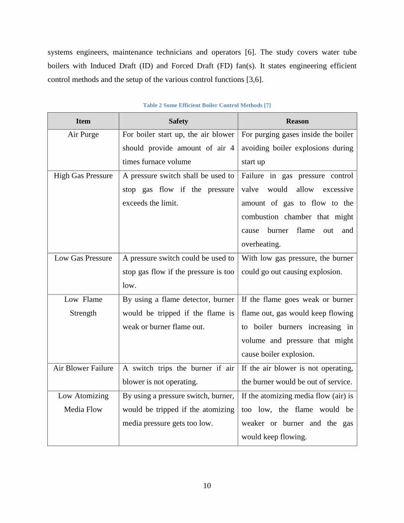
Table 2 Some Efficient Boiler Control Methods [7]
Item Safety Reason
Air Purge For boiler start up, the air blower
should provide amount of air 4
times furnace volume
For purging gases inside the boiler
avoiding boiler explosions during
start up
High Gas Pressure A pressure switch shall be used to
stop gas flow if the pressure
exceeds the limit.
Failure in gas pressure control
valve would allow excessive
amount of gas to flow to the
combustion chamber that might
cause burner flame out and
overheating.
Low Gas Pressure A pressure switch could be used to
stop gas flow if the pressure is too
low.
With low gas pressure, the burner
could go out causing explosion.
Low Flame
Strength
By using a flame detector, burner
would be tripped if the flame is
weak or burner flame out.
If the flame goes weak or burner
flame out, gas would keep flowing
to boiler burners increasing in
volume and pressure that might
cause boiler explosion.
Air Blower Failure A switch trips the burner if air
blower is not operating.
If the air blower is not operating,
the burner would be out of service.
Low Atomizing
Media Flow
By using a pressure switch, burner,
would be tripped if the atomizing
media pressure gets too low.
If the atomizing media flow (air) is
too low, the flame would be
weaker or burner and the gas
would keep flowing.
11
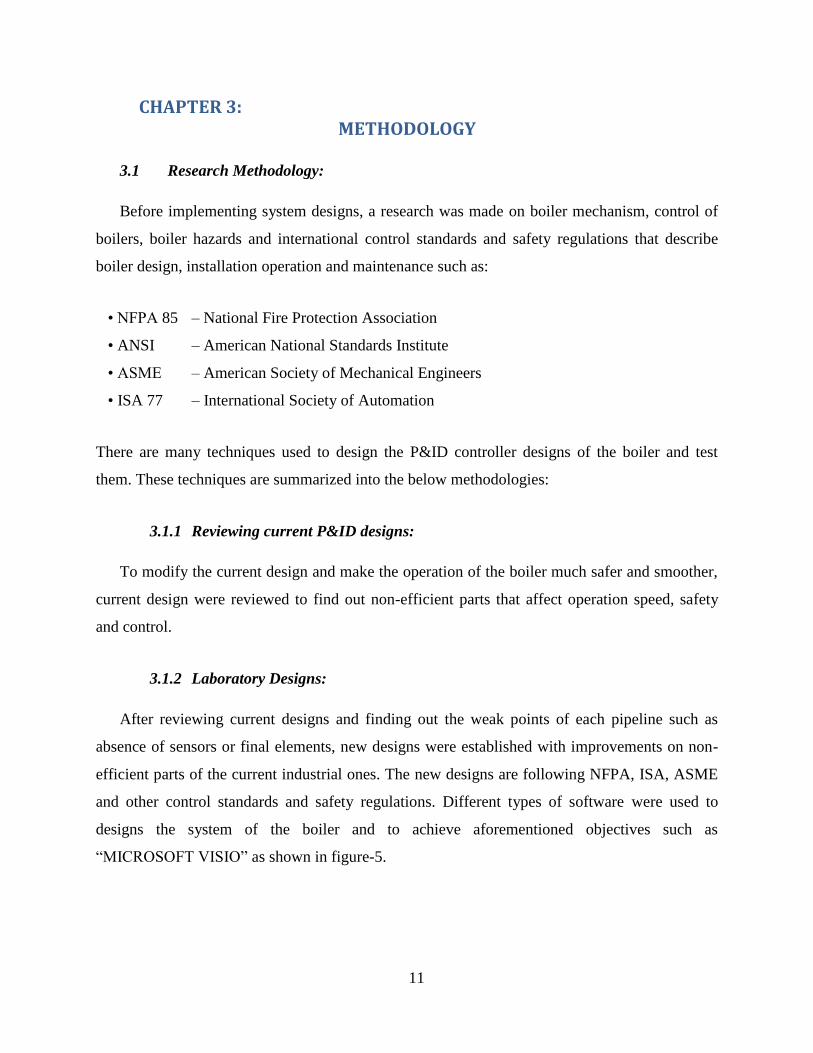
CHAPTER 3: METHODOLOGY
3.1 Research Methodology:
Before implementing system designs, a research was made on boiler mechanism, control of
boilers, boiler hazards and international control standards and safety regulations that describe
boiler design, installation operation and maintenance such as:
• NFPA 85 – National Fire Protection Association
• ANSI – American National Standards Institute
• ASME – American Society of Mechanical Engineers
• ISA 77 – International Society of Automation
There are many techniques used to design the P&ID controller designs of the boiler and test
them. These techniques are summarized into the below methodologies:
3.1.1 Reviewing current P&ID designs:
To modify the current design and make the operation of the boiler much safer and smoother,
current design were reviewed to find out non-efficient parts that affect operation speed, safety
and control.
3.1.2 Laboratory Designs:
After reviewing current designs and finding out the weak points of each pipeline such as
absence of sensors or final elements, new designs were established with improvements on non-
efficient parts of the current industrial ones. The new designs are following NFPA, ISA, ASME
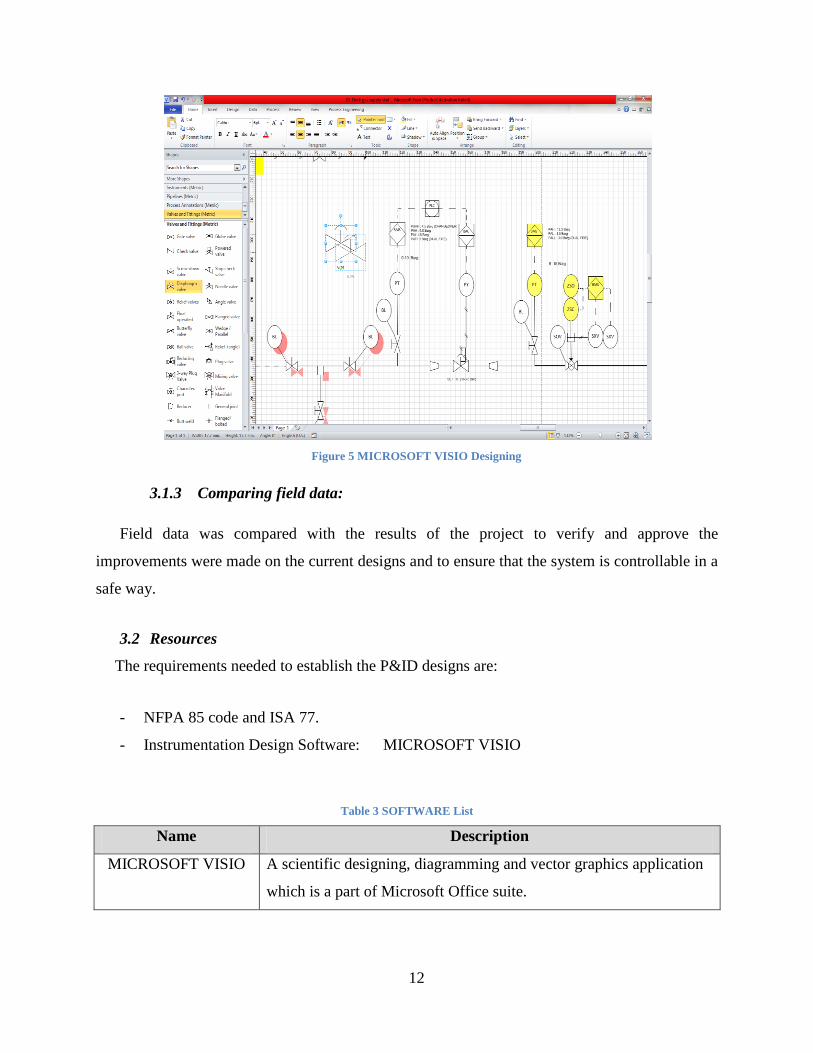
and other control standards and safety regulations. Different types of software were used to
designs the system of the boiler and to achieve aforementioned objectives such as
“MICROSOFT VISIO” as shown in figure-5.
12
Figure 5 MICROSOFT VISIO Designing
3.1.3 Comparing field data:
Field data was compared with the results of the project to verify and approve the
improvements were made on the current designs and to ensure that the system is controllable in a
safe way.
3.2 Resources
The requirements needed to establish the P&ID designs are:
- NFPA 85 code and ISA 77.
- Instrumentation Design Software: MICROSOFT VISIO
Table 3 SOFTWARE List
Name Description
MICROSOFT VISIO A scientific designing, diagramming and vector graphics application
which is a part of Microsoft Office suite.

13
3.3 Work Schedule:
The project was planned on two semesters. The first semester is to make a research on boiler
mechanism, control of boilers, boiler hazards and international control standards and to find the
suitable software to be used for implementing the new P&ID designs and to achieve the designs
of oil, gas and atomizing media skid. The second semester is to continue P&ID designing and
compare the new designs with the old one. Moreover, it is to improve boiler control system by
finding the best valve sizing for each pipeline of the boiler and to calculate the system efficiency
using heat losses efficiency equations.
Table 4 Gantt chart
Number of
weeks 1 2 3 4 5 6 7 8 9 10 11 12 13 14 15 16 17 18 19 20 21 22 23 24 25 26 27 28
Research Work
Reviewing Current
P&ID Designs
Designing P&ID
Controller
Control Valve
Sizing
Design Work
Continues
Comparing Old
and New Designs
Calculating
System Efficiency
Paper Work and
Final Report
14
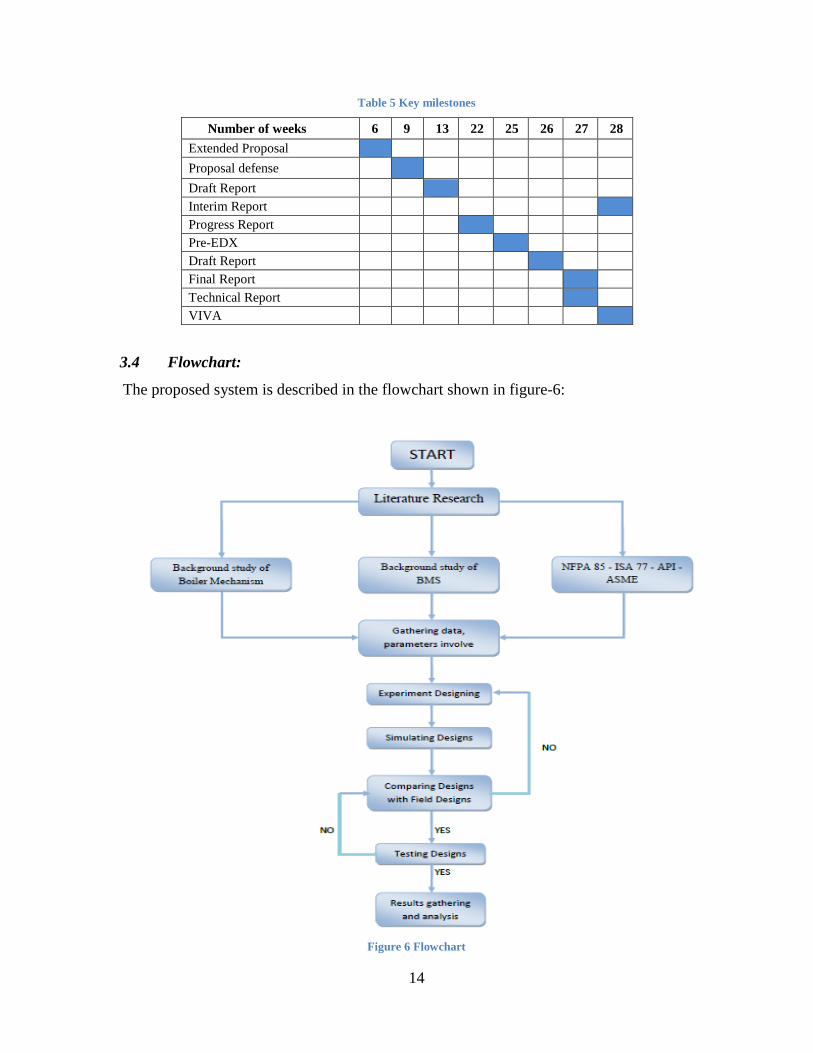
Table 5 Key milestones
Number of weeks 6 9 13 22 25 26 27 28
Extended Proposal
Proposal defense
Draft Report
Interim Report
Progress Report
Pre-EDX
Draft Report
Final Report
Technical Report
VIVA
3.4 Flowchart:
The proposed system is described in the flowchart shown in figure-6:
Figure 6 Flowchart
15
CHAPTER 4: Discussion & Results
Boiler could be operated with high efficiency and high safety control methods to produce a
continuous supply of steam with the lowest cost of boiler inputs. This is shown in the
improvements were done on oil, gas, atomizing media skid and burners designs shown in
Appendix-I.
Steam generators and boilers are large plants have separate P&ID designs representing
process lines and equipment such as steam, condensate, feed water, atomizing media and fuel
etc. Each P&ID design was made following minimum requirements of designing parameters
such as control (pressure, temperature and flow), safety, cost and efficiency as shown in table-6.
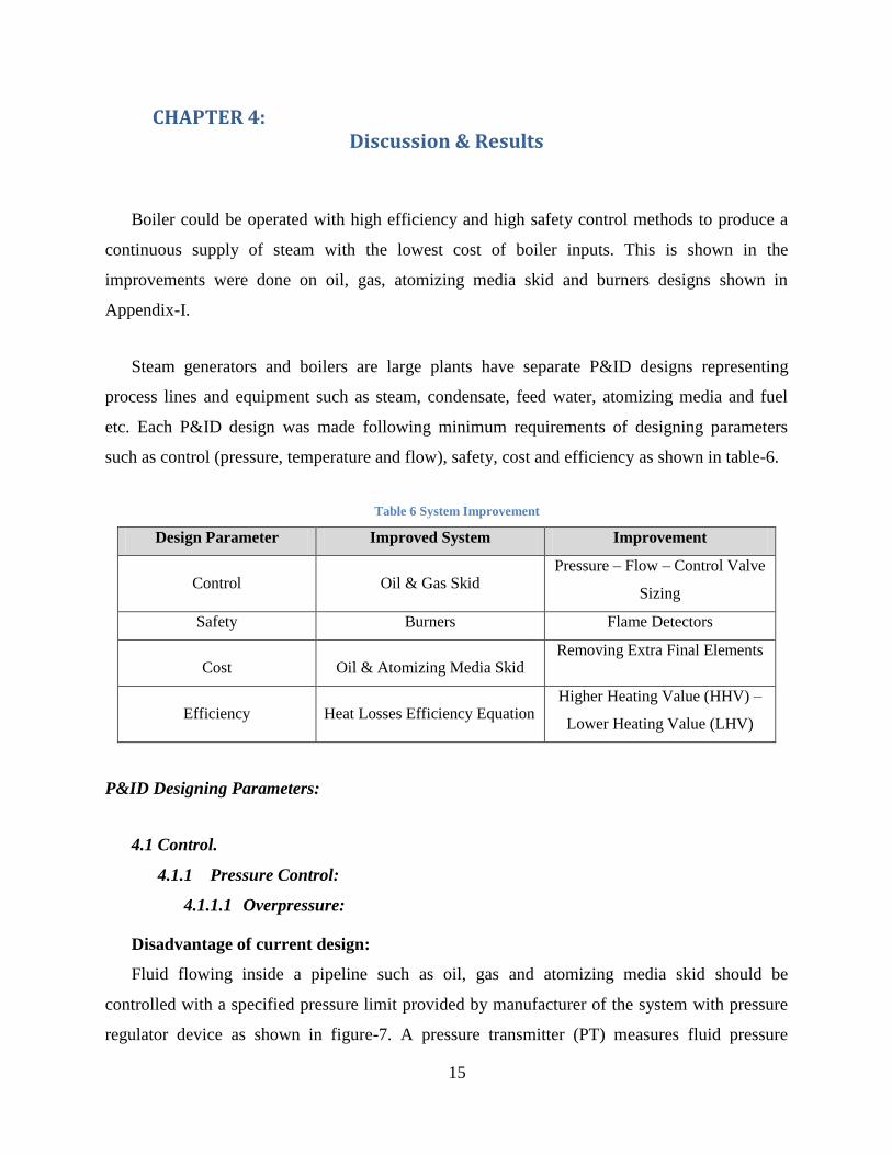
Table 6 System Improvement
Design Parameter Improved System Improvement
Control Oil & Gas Skid Pressure – Flow – Control Valve
Sizing
Safety Burners Flame Detectors
Cost Oil & Atomizing Media Skid Removing Extra Final Elements
Efficiency Heat Losses Efficiency Equation Higher Heating Value (HHV) –
Lower Heating Value (LHV)
P&ID Designing Parameters:
4.1 Control.
4.1.1 Pressure Control:
4.1.1.1 Overpressure:
Disadvantage of current design:
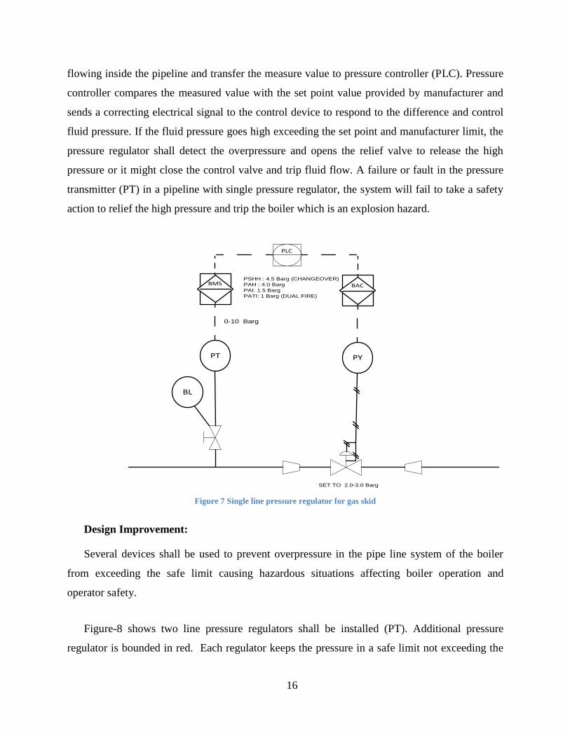
Fluid flowing inside a pipeline such as oil, gas and atomizing media skid should be
controlled with a specified pressure limit provided by manufacturer of the system with pressure
regulator device as shown in figure-7. A pressure transmitter (PT) measures fluid pressure
16
flowing inside the pipeline and transfer the measure value to pressure controller (PLC). Pressure
controller compares the measured value with the set point value provided by manufacturer and
sends a correcting electrical signal to the control device to respond to the difference and control
fluid pressure. If the fluid pressure goes high exceeding the set point and manufacturer limit, the
pressure regulator shall detect the overpressure and opens the relief valve to release the high
pressure or it might close the control valve and trip fluid flow. A failure or fault in the pressure
transmitter (PT) in a pipeline with single pressure regulator, the system will fail to take a safety
action to relief the high pressure and trip the boiler which is an explosion hazard.
BL
PT
BMS BAC
PY
PLC
SET TO 2.0-3.0 Barg
PSHH : 4.5 Barg (CHANGEOVER)
PAH : 4.0 Barg
PAI: 1.5 Barg
PATI: 1 Barg (DUAL FIRE)
0-10 Barg
Figure 7 Single line pressure regulator for gas skid
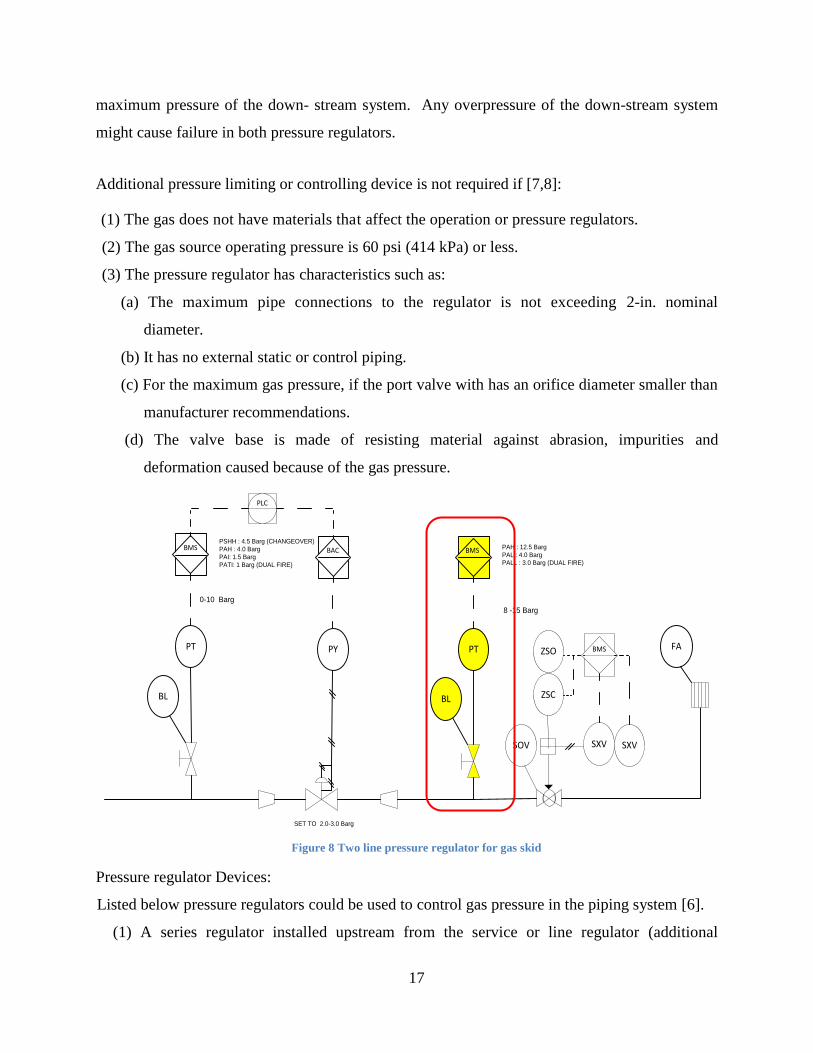
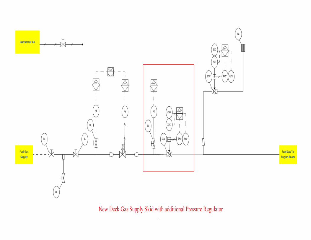
Design Improvement:
Several devices shall be used to prevent overpressure in the pipe line system of the boiler
from exceeding the safe limit causing hazardous situations affecting boiler operation and
operator safety.
Figure-8 shows two line pressure regulators shall be installed (PT). Additional pressure
regulator is bounded in red. Each regulator keeps the pressure in a safe limit not exceeding the
17
maximum pressure of the down- stream system. Any overpressure of the down-stream system
might cause failure in both pressure regulators.
Additional pressure limiting or controlling device is not required if [7,8]:
(1) The gas does not have materials that affect the operation or pressure regulators.
(2) The gas source operating pressure is 60 psi (414 kPa) or less.
(3) The pressure regulator has characteristics such as:
(a) The maximum pipe connections to the regulator is not exceeding 2-in. nominal
diameter.
(b) It has no external static or control piping.
(c) For the maximum gas pressure, if the port valve with has an orifice diameter smaller than
manufacturer recommendations.
(d) The valve base is made of resisting material against abrasion, impurities and
deformation caused because of the gas pressure.
BL
PT
BMS BAC
PY
BL
PT
BMS
PLC
SOV
ZSC
ZSO BMS
SXV SXV
FA
SET TO 2.0-3.0 Barg
PAH : 12.5 Barg
PAL : 4.0 Barg
PALL : 3.0 Barg (DUAL FIRE)
8 -15 Barg
PSHH : 4.5 Barg (CHANGEOVER)
PAH : 4.0 Barg
PAI: 1.5 Barg
PATI: 1 Barg (DUAL FIRE)
0-10 Barg
Figure 8 Two line pressure regulator for gas skid
Pressure regulator Devices:
Listed below pressure regulators could be used to control gas pressure in the piping system [6].
(1) A series regulator installed upstream from the service or line regulator (additional
18
pressure regulator bounded in red shown in figure-8).
(2) A monitoring regulator connected in series with the line pressure regulator (PT).
(3) Limit switch close/open (ZSC/ZSO) to operate the control valve responding to the
received signal from BMS.
(4) Automatic shut off valve connected in series with pressure regulator to shut off when the
pressure of piping system exceeds manufacturer limits (SOV).
(5) A liquid seal relief device opens at the desired pressure with high efficiency (FA).
(6) Solenoid valve (SXV).
Vents:
The size of the vent device should be same or greater than the outer relief valve (FA) [9].
4.1.1.2 Back Pressure:
Back pressure preventers and Protective devices should be installed before pressure
regulators close to the equipment connected to compressed fluid as oil or supply system [6]. Gas
and air combustion mixers do not require installation of back pressure preventers unless they are
connected compressed air or oxygen at pressures of 5 psi (34 kPa) or more [7,9].
Figure-9 shows back pressure protective Devices which are installed before pressure
regulator devices to protect equipment from damages that might be caused by back pressure of
gas or supplied air and prevent it from returning to gas and air storages. Protective devices are:
(1) Check valves (CH 062).
(2) Three-way valves (shown in figure-9).
(3) Reverse flow indicators controlling positive solenoid valves (SXV 062) .
(4) Normally closed air-actuated positive shutoff pressure regulators (pressure regulators
shown in figure-8) .
Solenoid valves (SXV) might affect the operation of the pressure relieving valve (FA), so it
is required to install duplicate relief valves, each having enough capacity to protect the system as
shown in figure-8 or three-way valve as shown in figure-9 so that only one device can be
rendered inoperative at a time [6,9]. A gas shutoff valve shall be implemented upstream of each

19
gas pressure regulator. If two gas pressure regulators are connected in series, a manual gas
shutoff valve shall not be installed at the second regulator [8].
BMSF16ZSO062
F16ZSC062
F16SXV062
F16CH062
F16BL
062
Three-way valves
Figure 9 Back pressure protective system
Low-Pressure Protection
A low-pressure protective device should be implemented between the meter and the gas
utilization equipment as gas compressors might produce a vacuum causing dangerous reduction
in gas pressure.
Low-pressure protective devices:
Mechanical or diaphragm-operated or electrically operated low pressure shutoff valves shown in
figure-8 (SOV).
Other Safety Equipment:
More safety equipment shall be used as manual reset valves (MV), high-temperature limit
switches (ZSC/ZSO), shutoff valves (SOV), airflow switches, door switches and gas valves [6].
20
4.1.2 Flow Control.
4.1.2.1 Control Valve Sizing:
Control valves are used to control flow, pressure temperature and fluid level by responding to
signal received from the controller which compares the set point to the control variable (pressure,
temperature, level and/or flow) which is provided by gauge sensor and monitoring elements.
Control valves are controlled with petitioners such as electrical, hydraulic and pneumatic
actuators using either 4-20 mA electric signal or 3-15 Psi. Fluid flow rate depends on the size of
the control valve and the valve travel, as the travel is varied from 0 to 100 percent. Fluid flow
characteristic refers to the characteristic observed during burner operation.
Disadvantage of current design:
It takes more than 30 minutes to ignite and run the burner. This time delay affects boiler
operation and the quantity of the generated steam.
Improvement
To improve fluid flow and operation speed, valve size shall be changed following Flow
Equations for Sizing Control Valves standard (ANSI/ISA-75.01.01) to match flow characteristic
needed. For good fluid flow control, it is essential to select the correct size for the valve as well
as the valve characteristic. Analyses of valve sizing and selection processes are shown below
[13].
Recommended Velocities for burner fluids:
Maximum operating condition values:
- Liquids:
< 10 m/s < 33 ft/s
- Air:
< 1/3 MA (Mach)
= 1/3 x (330 m/s)
< 110 m/s < 360 ft/s
- Dry Gases and Steam:
21
<110 m/s < 360 ft/s
- Flashing Liquids:
< 60 m/s < 196 ft/s
Control Valve Sizing Calculations:
1) Water Valve Sizing:
It is essential to determine the valve sizing in boiler burner for 600,000 pounds per hour
water flow with no density consideration. A rule of thumb for pressure drop is one third of the
pressure drop across the system for the pressure drop across the valve.
Q = gpm
SG = specific gravity
ΔP = pressure drop across valve
Cv = Rate Capacity Variable = GPM (√ SG ÷ ΔP)
The conversion of pounds per hour is:
600,000 ÷ (8.34 x 60) = 1200 GPM
If the pump discharge pressure is 2000 psig and the drum pressure is 1400 psig, the differential
pressure is:
600 ÷ 3 = 200 psig.
Cv = GPM √(SG ÷ ΔP)
Cv = 1200 x √( 1 ÷ 200) = 84.84
Cv = 300 x √( 1 ÷ 200) = 14.14
The lower pressure drop of 150 psi for a lower flow rate.
Cv = 300 x √( 1 ÷ 150) = 24.5
If the water temperature is 450°F, then the change in specific gravity must be considered. The
specific gravity of water at 450°F is 0.827.
Cv = 1200 x √( 0.827 ÷ 200) = 77.16
Cv = 300 x √( 0.827 ÷ 200) = 12.86
Assume a lower pressure drop of 150 psi for a lower flow rate.
One fourth Cv = 300 x √( 0.827 ÷ 150) = 9.65
22
Referring to table-7 equal percentages of rate capacity variable Cv, a three or four inch valve
can be used. If a three inch valve is selected, it is almost 100 percent open. A four inch valve
should be selected and would have less line pressure drop. For best control, the Cv value should
be 20 percent at the lowest flow and 80 percent at the highest flow rate.
At 60°F water temperature, the Cv is 84.84 and at 450°F, the Cv is 77.16.
2) Steam Valve:
The calculations for 300,000 pounds per hour steam flow at 1000 psi and 800°F would be:
The equation is:
Cv = pph / 63 x √(ΔP ÷ V)
pph = pounds per hour
V = specific volume
ΔP = differential pressure across the valve
If a 400 psi system pressure drop and one third across the valve, the valve pressure drop would
be 133 psi.
The specific volume for steam at 800°F superheated steam at 1000 psi is 0.6875.
Cv = 300,000 / 63 x √(133 ÷ 0.6875)
√133 ÷ 0.6875 = 13.9
Cv = 300000 ÷ (63x13.9) = 300000 ÷ 876 = 684
Referring to table-7 equal percentages of rate capacity variable Cv, either an eight inch valve or a
ten inch valve with reduced trim could be used.
3) Gas Valve Sizing:
This gas valve sizing is based on 100,000 SCFH. The 460 is degrees.
Cv = SCFH x √(460 + F°) SG ÷ 1360 x √(P1 x ΔP)
Cv = 100,000 (0.6) √(460 + 70° F) ÷ 1360 x √(30 x 10)
Cv = 100,000 (0.6) √530 ÷ 1360 x √300
Cv = 100,000 x 0.6 x 23.02 ÷ 1360 x 17.32
Cv = 100,000 x 13.8 ÷ 23555.2 = 58.59
Referring to table-7 equal percentages of rate capacity variable Cv, A three inch valve can be
used.
23
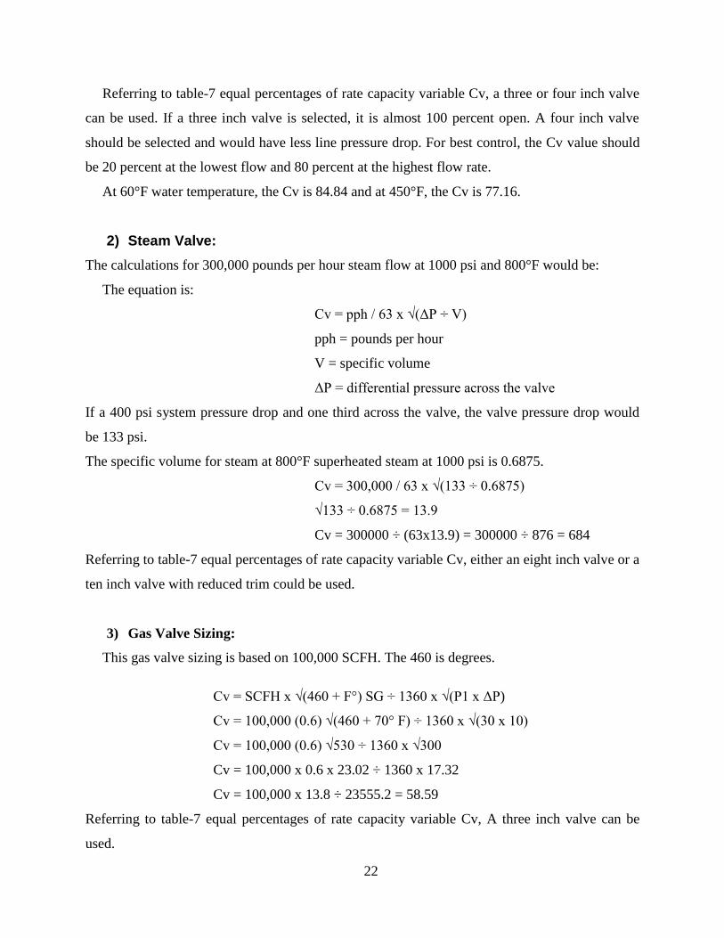
Table 7 Equal Percentages [13]
Valve Size Rated Cv 10 20 30 40 50 60 70 80 90 100
3 inch 95 4.45 6.25 8.78 12.3 17.3 24.4 34.2 48.1 67.6 95
4 inch 190 8.9 12.5 17.6 24.7 34.7 48.7 68.5 96.2 135 190
8 inch 420 19.7 27.6 38.8 54.6 76.7 108 151 213 299 420
10 inch* 420 19.7 27.6 38.8 54.6 76.7 108 151 213 299 420
10 inch 735 34.4 48.4 68 95.5 134 189 265 372 546 735
*10 inch valve with reduced trim note the Cv is the same as the eight inch valve.
For more information, reference to ANSI/ISA -75.01.01-2002
4.2 Safety.
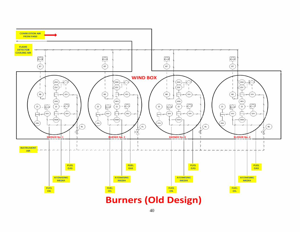
4.2.1 Boiler Burners:
Furnace or boiler burner is a combustion chamber that releases huge amount of heat. It also
works as heat exchanger as it transfers the released heat to the header system (water) to create
steam. Monitoring the control of burner temperature, pressure, time and turbulence is required to
maintain the combustion process stable.
Disadvantage of current design:
- Safety:
Combustion process should be controlled in a safe way by monitoring flame presence of the
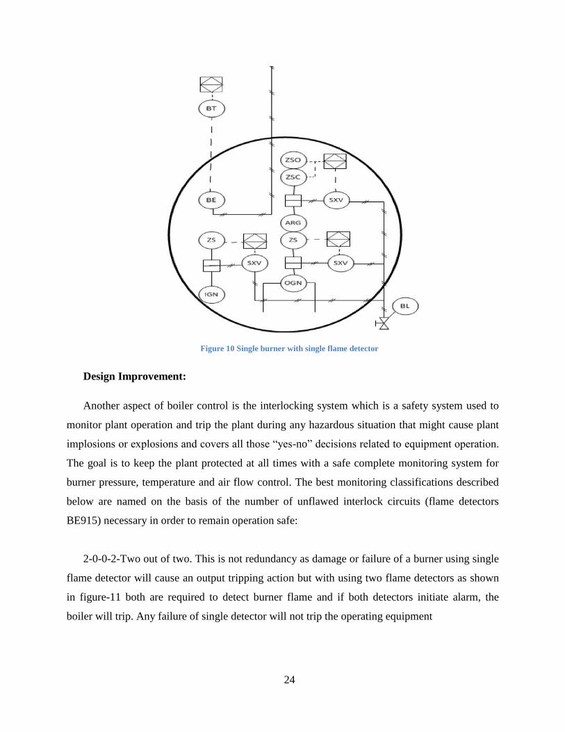
burners with flame detectors (BE915) as shown is figure-10. Some hazards can occur through a
healthy burner using single flame detector due to a failure or fault within the flame detector. In
this case, flame detector might fail to detect the flame presence of the burner and fail to initiate
alarm and to trip the combustion process. Moreover, it might launch a master fuel trip condition
while the burner is still operating in a healthy way. This hazard might cause damage to the
operators, combustion process, equipment, the environment and/or loss of money.
24
Figure 10 Single burner with single flame detector
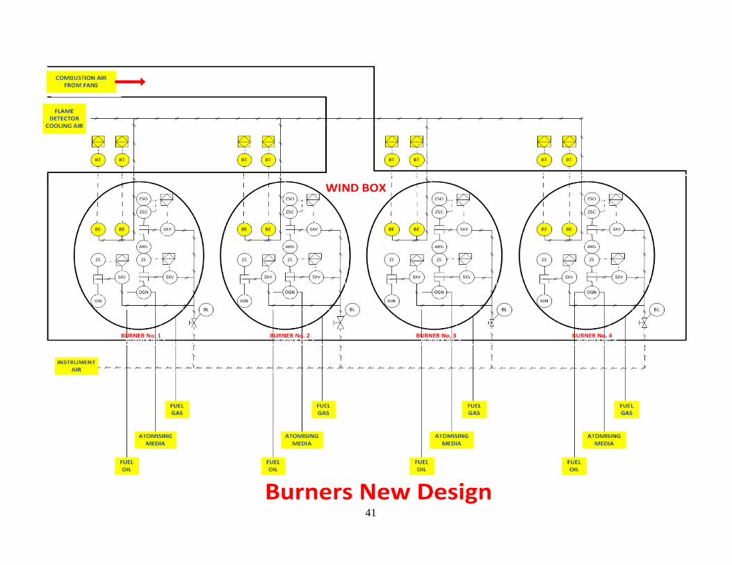
Design Improvement:
Another aspect of boiler control is the interlocking system which is a safety system used to
monitor plant operation and trip the plant during any hazardous situation that might cause plant
implosions or explosions and covers all those “yes-no” decisions related to equipment operation.
The goal is to keep the plant protected at all times with a safe complete monitoring system for
burner pressure, temperature and air flow control. The best monitoring classifications described
below are named on the basis of the number of unflawed interlock circuits (flame detectors
BE915) necessary in order to remain operation safe:
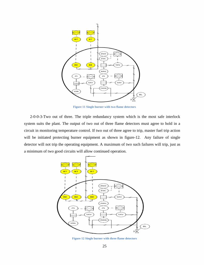
2-0-0-2-Two out of two. This is not redundancy as damage or failure of a burner using single
flame detector will cause an output tripping action but with using two flame detectors as shown
in figure-11 both are required to detect burner flame and if both detectors initiate alarm, the
boiler will trip. Any failure of single detector will not trip the operating equipment
25
Figure 11 Single burner with two flame detectors
2-0-0-3-Two out of three. The triple redundancy system which is the most safe interlock
system suits the plant. The output of two out of three flame detectors must agree to hold in a
circuit in monitoring temperature control. If two out of three agree to trip, master fuel trip action
will be initiated protecting burner equipment as shown in figure-12. Any failure of single
detector will not trip the operating equipment. A maximum of two such failures will trip, just as
a minimum of two good circuits will allow continued operation.
Figure 12 Single burner with three flame detectors
26
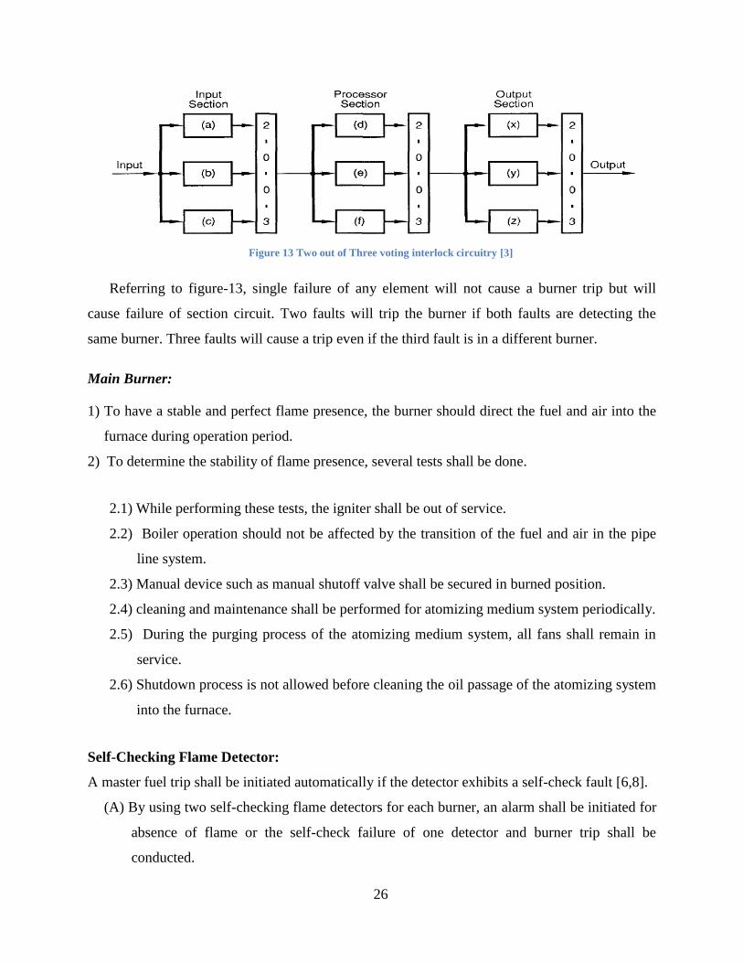
Figure 13 Two out of Three voting interlock circuitry [3]
Referring to figure-13, single failure of any element will not cause a burner trip but will
cause failure of section circuit. Two faults will trip the burner if both faults are detecting the
same burner. Three faults will cause a trip even if the third fault is in a different burner.
Main Burner:
1) To have a stable and perfect flame presence, the burner should direct the fuel and air into the
furnace during operation period.
2) To determine the stability of flame presence, several tests shall be done.
2.1) While performing these tests, the igniter shall be out of service.
2.2) Boiler operation should not be affected by the transition of the fuel and air in the pipe
line system.
2.3) Manual device such as manual shutoff valve shall be secured in burned position.
2.4) cleaning and maintenance shall be performed for atomizing medium system periodically.
2.5) During the purging process of the atomizing medium system, all fans shall remain in
service.
2.6) Shutdown process is not allowed before cleaning the oil passage of the atomizing system
into the furnace.
Self-Checking Flame Detector:
A master fuel trip shall be initiated automatically if the detector exhibits a self-check fault [6,8].
(A) By using two self-checking flame detectors for each burner, an alarm shall be initiated for
absence of flame or the self-check failure of one detector and burner trip shall be
conducted.
27
(B) If one detector is out of service, the other one shall trip the burner for losing flame or self-
check fault.
Loss of flame in more than one burner is a hazardous situation that requires initiating master
fuel trip. During flame loss situation, an alarm should be initiated as the fuel input does not
ignite. Periodic tests shall be done on flame tripping to validate function efficiency [6,9].
4.3 Cost.
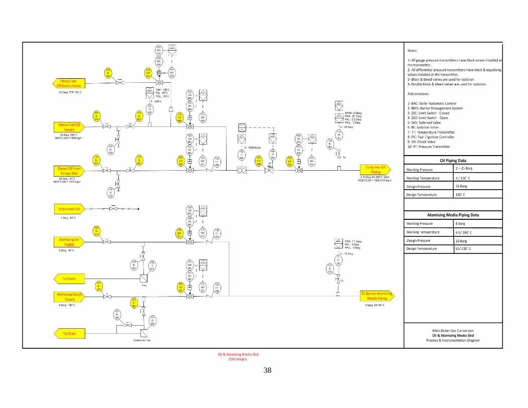
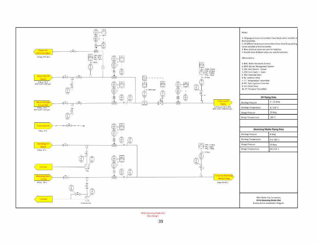
4.3.1 Oil and Atomizing Media Skid:
Oil and atomizing media skid describes the pipeline systems that deliver oil and atomizing
media (air) from storage tanks to boiler burners to be mixed together for the combustion process.
The pipeline contains gauge, control and safety elements such as control valves, limit switches
closed/open and pressure, temperature and flow transmitters.
Disadvantage of current design:
- Cost:
Current design of oil and atomizing media skid has extra final elements which are used for
safety or control such by handling or stopping the fluid flow of process media in a specified
location such as isolation valves (BL302) with an average cost of $500-600 (average cost in
American market provided by vendors) and solenoid valves (SXV069) with an average cost of
$139.94 (average cost in American market provided by vendors) shown in figure-14. Those
elements are installed in addition with other safety and control elements that can secure and
control the process of fluid flow in a safe way such as control valves and limit switches
close/open (ZSO/ZSC 065).
Limit switch is a switch that controls an electrical circuit by opening and closing. If the
switch is in closed position, current starts flowing to the connected device. If it is opened, the
electrical current stops flowing. Installation of additional safety elements will increase plant size
and plant and maintenance cost.
28
F16FT
064 P-4
BAC
I-1
FIC
F16FY
064
BAC
0 – 9500 Kg/hr
F16SXV069
F15ST
302
F15BL
301 F15BL
302
Condensate Trap
Figure 14 Additional Final Elements
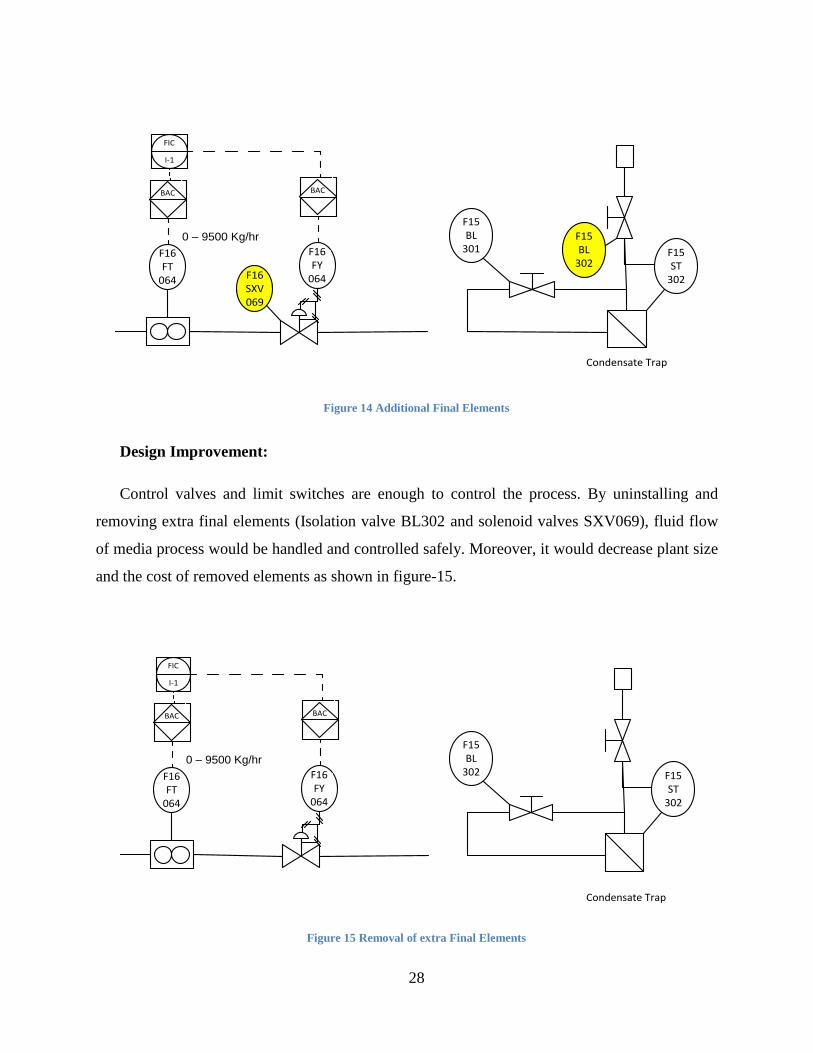
Design Improvement:
Control valves and limit switches are enough to control the process. By uninstalling and
removing extra final elements (Isolation valve BL302 and solenoid valves SXV069), fluid flow
of media process would be handled and controlled safely. Moreover, it would decrease plant size
and the cost of removed elements as shown in figure-15.
F16FT
064
BAC
I-1
FIC
F16FY
064
BAC
0 – 9500 Kg/hr
F15ST
302
F15BL
302
Condensate Trap
Figure 15 Removal of extra Final Elements

29
4.4 Efficiency.
Efficiency is a very important criterion in Boiler P&ID Design. Efficiency depends on fuel
type either gas or oil. Current efficiency of gas fired steam boiler is about 70% and it is about
85% for oil fired boilers (Efficiency percentage is identified by vendors recommending to use oil
instead of gas). Higher moisture and wet content in the fuel reduces its efficiency.
The best basic method to calculate boiler efficiency is heat loss method by calculating heat
input and heat losses. Boiler Efficiency is the ratio between output and input. Efficiency
calculations stated below are based on gas fired boilers and were recommended by vendors to
calculate efficiency of the system. The value of heat losses were obtained from the data sheets
of6 the current system. To obtain superheated steam, boiler is operated with higher heating value
(HHV) of temperature to get a very dry steam with zero moisture level. With lower heating value
(LHV), boiler produces normal steam.
4.4.1 Heat Losses with higher heating value (HHV):
1. Combustion heat losses:
Combustion takes place to release huge amount of heat. Flue gases leave the burner with high
temperature which is considered combustion heat losses.
HHV: Higher heating value
CP: Constant Pressure inside the burner
Tb: Temperature of flue gases before releasing
Ta: Temperature of flue gases inside the relief valve while releasing
Combustion Heat Losses, Lc = Unit storage fuel x CP x (Tb-Ta) x 100/HHV
= 13.5 x 0.24 x (303 -81) x 100 / 13102.36
= 5.42 %
30
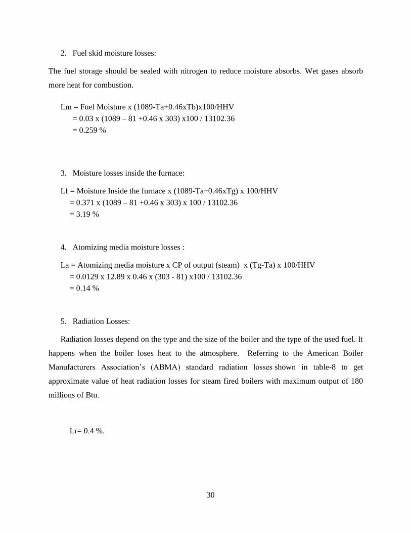
2. Fuel skid moisture losses:
The fuel storage should be sealed with nitrogen to reduce moisture absorbs. Wet gases absorb
more heat for combustion.
Lm = Fuel Moisture x (1089-Ta+0.46xTb)x100/HHV
= 0.03 x (1089 – 81 +0.46 x 303) x100 / 13102.36
= 0.259 %
3. Moisture losses inside the furnace:
Lf = Moisture Inside the furnace x (1089-Ta+0.46xTg) x 100/HHV
= 0.371 x (1089 – 81 +0.46 x 303) x 100 / 13102.36
= 3.19 %
4. Atomizing media moisture losses :
La = Atomizing media moisture x CP of output (steam) x (Tg-Ta) x 100/HHV
= 0.0129 x 12.89 x 0.46 x (303 - 81) x100 / 13102.36
= 0.14 %
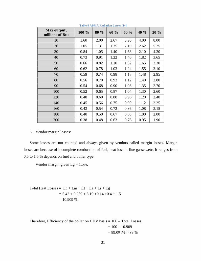
5. Radiation Losses:
Radiation losses depend on the type and the size of the boiler and the type of the used fuel. It
happens when the boiler loses heat to the atmosphere. Referring to the American Boiler
Manufacturers Association’s (ABMA) standard radiation losses shown in table-8 to get
approximate value of heat radiation losses for steam fired boilers with maximum output of 180
millions of Btu.
Lr= 0.4 %.
31
Table 8 ABMA Radiation Losses [14]
Max output‚
millions of Btu 100 % 80 % 60 % 50 % 40 % 20 %
10 1.60 2.00 2.67 3.20 4.00 8.00
20 1.05 1.31 1.75 2.10 2.62 5.25
30 0.84 1.05 1.40 1.68 2.10 4.20
40 0.73 0.91 1.22 1.46 1.82 3.65
50 0.66 0.82 1.10 1.32 1.65 3.30
60 0.62 0.78 1.03 1.24 1.55 3.10
70 0.59 0.74 0.98 1.18 1.48 2.95
80 0.56 0.70 0.93 1.12 1.40 2.80
90 0.54 0.68 0.90 1.08 1.35 2.70
100 0.52 0.65 0.87 1.04 1.30 2.60
120 0.48 0.60 0.80 0.96 1.20 2.40
140 0.45 0.56 0.75 0.90 1.12 2.25
160 0.43 0.54 0.72 0.86 1.08 2.15
180 0.40 0.50 0.67 0.80 1.00 2.00
200 0.38 0.48 0.63 0.76 0.95 1.90
6. Vendor margin losses:
Some losses are not counted and always given by vendors called margin losses. Margin
losses are because of incomplete combustion of fuel, heat loss in flue gasses..etc. It ranges from
0.5 to 1.5 % depends on fuel and boiler type.
Vendor margin given Lg = 1.5%.
Total Heat Losses = Lc + Lm + Lf + La + Lr + Lg
= 5.42 + 0.259 + 3.19 +0.14 +0.4 + 1.5
= 10.909 %
Therefore, Efficiency of the boiler on HHV basis = 100 – Total Losses
= 100 – 10.909
= 89.091% ≈ 89 %
32
4.4.2 Efficiency with lower heating value (LHV):
= HHV efficiency x HHV / LHV
= 89.091 x 13102.36 /12691.8
= 91.973 % ≈ 92 %
With the new P&ID designs of gas fired steam boilers efficiency increases from 70% to 89%
representing the lowest losses of heat during combustion process with higher and lower heating
value.
33
CHAPTER 5: Conclusion
Boiler is used to produce steam for generating electricity, heat and personal uses. Many
hazards are affecting boiler operation process causing boiler implosions, operator injures and
loss of life. An improvement of boiler P&ID designs could be done to avoid any hazards
affecting operation process. By following safety control methods, boiler P&ID would include
extra safety elements and sensors that make boiler operation much safer avoiding any hazardous
situation. Efficiency of current designs improved from 70% to 89%. All control methods and
boiler designs are based on several standards such as NFPA 85, ASME and ISA 77 published
recently in order to implement safety control requirements for BMS systems.
Future works might follow newer standards and safety regulations with upgraded safety
system requirements and proper boiler designs as well as simulation software to get the highest
efficiency of the control system. Moreover, with a proper arrangement and sizing of boiler
components operation process becomes smoother and easy to be controlled with higher
efficiency. The correct selection of safety equipment and boiler components has very important
benefits to operation costs and boiler safety. Equipment selection has to be made in accordance to
risk reduction.
34
Recommendations Industrial Recommendations:
Industrial fields using oil/gas fired steam generators should follow the results of the project
as well as international control standards and safety regulations to improve the control system
and fulfil the minimum requirements of safety limits.
Academic Recommendations:
UTP automation and control laboratories should be supported with P&ID simulation
software that makes P&ID design and simulation easier than before such as;
1- SCADA
2- ELECWORKS
35
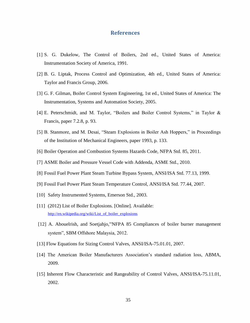
References
[1] S. G. Dukelow, The Control of Boilers, 2nd ed., United States of America:
Instrumentation Society of America, 1991.
[2] B. G. Liptak, Process Control and Optimization, 4th ed., United States of America:
Taylor and Francis Group, 2006.
[3] G. F. Gilman, Boiler Control System Engineering, 1st ed., United States of America: The
Instrumentation, Systems and Automation Society, 2005.
[4] E. Peterschmidt, and M. Taylor, “Boilers and Boiler Control Systems,” in Taylor &
Francis, paper 7.2.8, p. 93.
[5] B. Stanmore, and M. Desai, “Steam Explosions in Boiler Ash Hoppers,” in Proceedings
of the Institution of Mechanical Engineers, paper 1993, p. 133.
[6] Boiler Operation and Combustion Systems Hazards Code, NFPA Std. 85, 2011.
[7] ASME Boiler and Pressure Vessel Code with Addenda, ASME Std., 2010.
[8] Fossil Fuel Power Plant Steam Turbine Bypass System, ANSI/ISA Std. 77.13, 1999.
[9] Fossil Fuel Power Plant Steam Temperature Control, ANSI/ISA Std. 77.44, 2007.
[10] Safety Instrumented Systems, Emerson Std., 2003.
[11] (2012) List of Boiler Explosions. [Online]. Available:
http://en.wikipedia.org/wiki/List_of_boiler_explosions
[12] A. Abouelrish, and Soetjahjo,“NFPA 85 Compliances of boiler burner management
system”, SBM Offshore Malaysia, 2012.
[13] Flow Equations for Sizing Control Valves, ANSI/ISA-75.01.01, 2007.
[14] The American Boiler Manufacturers Association’s standard radiation loss, ABMA,
2009.
[15] Inherent Flow Characteristic and Rangeability of Control Valves, ANSI/ISA-75.11.01,
2002.

36
[16] Scientific Apparatus Makers Association standard, SAMA-54.01.01, 2004.
[17] National Fuel Gas Code-The safety benchmark for fuel gas installations, NFPA Std. 54,
1999.
[18] H. D. Baumann, Control Valve Primer, 4th ed., United States of America:
Instrumentation Society of America, 2012.
[19] G. Borden, and P. G. Friedmann, Control Valves: Practical Guides for Measurement and
Control, 4th ed.: ISA, 1998.
[20] R. Newton, DuPont to standardize on Bentley Open Plant P&ID., United States of
America: Instrumentation Society of America, 2012.

37
Appendices
Appendix-I
Results
Note:
Additional Control Elements are highlighted or bounded in red.
38
39
40
41
42
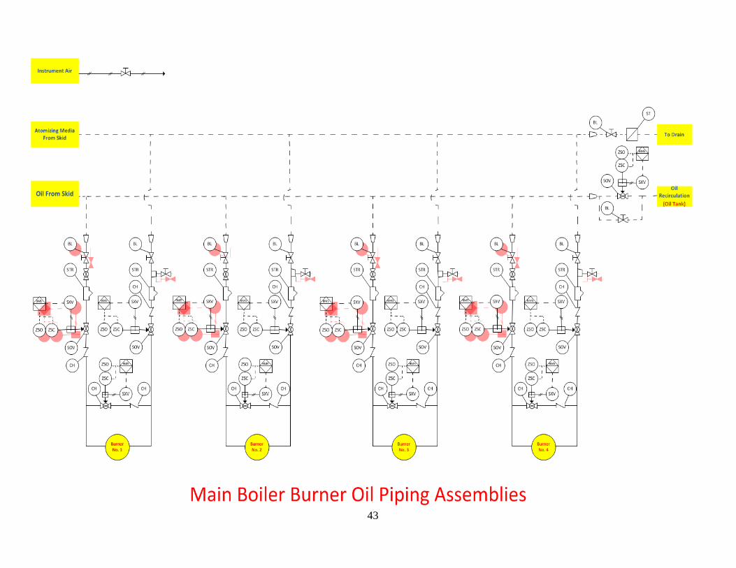
43

44
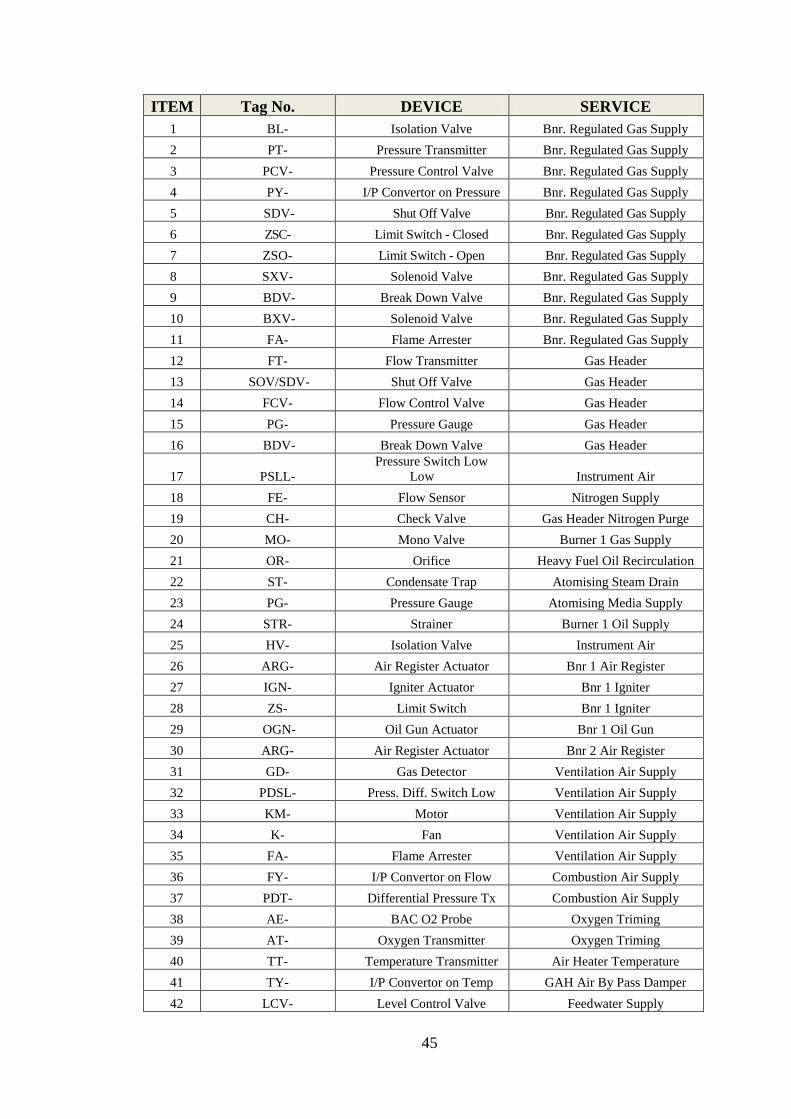
Appendix-II
Glossary
45
ITEM Tag No. DEVICE SERVICE
1 BL- Isolation Valve Bnr. Regulated Gas Supply
2 PT- Pressure Transmitter Bnr. Regulated Gas Supply
3 PCV- Pressure Control Valve Bnr. Regulated Gas Supply
4 PY- I/P Convertor on Pressure Bnr. Regulated Gas Supply
5 SDV- Shut Off Valve Bnr. Regulated Gas Supply
6 ZSC- Limit Switch - Closed Bnr. Regulated Gas Supply
7 ZSO- Limit Switch - Open Bnr. Regulated Gas Supply
8 SXV- Solenoid Valve Bnr. Regulated Gas Supply
9 BDV- Break Down Valve Bnr. Regulated Gas Supply
10 BXV- Solenoid Valve Bnr. Regulated Gas Supply
11 FA- Flame Arrester Bnr. Regulated Gas Supply
12 FT- Flow Transmitter Gas Header
13 SOV/SDV- Shut Off Valve Gas Header
14 FCV- Flow Control Valve Gas Header
15 PG- Pressure Gauge Gas Header
16 BDV- Break Down Valve Gas Header
17 PSLL-
Pressure Switch Low
Low Instrument Air
18 FE- Flow Sensor Nitrogen Supply
19 CH- Check Valve Gas Header Nitrogen Purge
20 MO- Mono Valve Burner 1 Gas Supply
21 OR- Orifice Heavy Fuel Oil Recirculation
22 ST- Condensate Trap Atomising Steam Drain
23 PG- Pressure Gauge Atomising Media Supply
24 STR- Strainer Burner 1 Oil Supply
25 HV- Isolation Valve Instrument Air
26 ARG- Air Register Actuator Bnr 1 Air Register
27 IGN- Igniter Actuator Bnr 1 Igniter
28 ZS- Limit Switch Bnr 1 Igniter
29 OGN- Oil Gun Actuator Bnr 1 Oil Gun
30 ARG- Air Register Actuator Bnr 2 Air Register
31 GD- Gas Detector Ventilation Air Supply
32 PDSL- Press. Diff. Switch Low Ventilation Air Supply
33 KM- Motor Ventilation Air Supply
34 K- Fan Ventilation Air Supply
35 FA- Flame Arrester Ventilation Air Supply
36 FY- I/P Convertor on Flow Combustion Air Supply
37 PDT- Differential Pressure Tx Combustion Air Supply
38 AE- BAC O2 Probe Oxygen Triming
39 AT- Oxygen Transmitter Oxygen Triming
40 TT- Temperature Transmitter Air Heater Temperature
41 TY- I/P Convertor on Temp GAH Air By Pass Damper
42 LCV- Level Control Valve Feedwater Supply

46
43 TCV-
Temperature Control
Valve Water Drum
44 GL- Isolation Globe Valve Boiler Drum Level
45 LSHH- Level Switch - High High Boiler Drum Level
47
Appendix-III
ISA Control Diagramming System
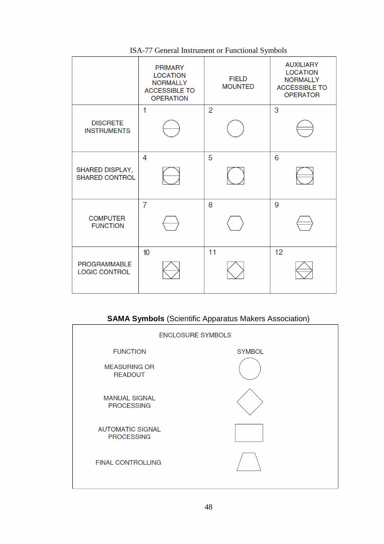
48
ISA-77 General Instrument or Functional Symbols
SAMA Symbols (Scientific Apparatus Makers Association)
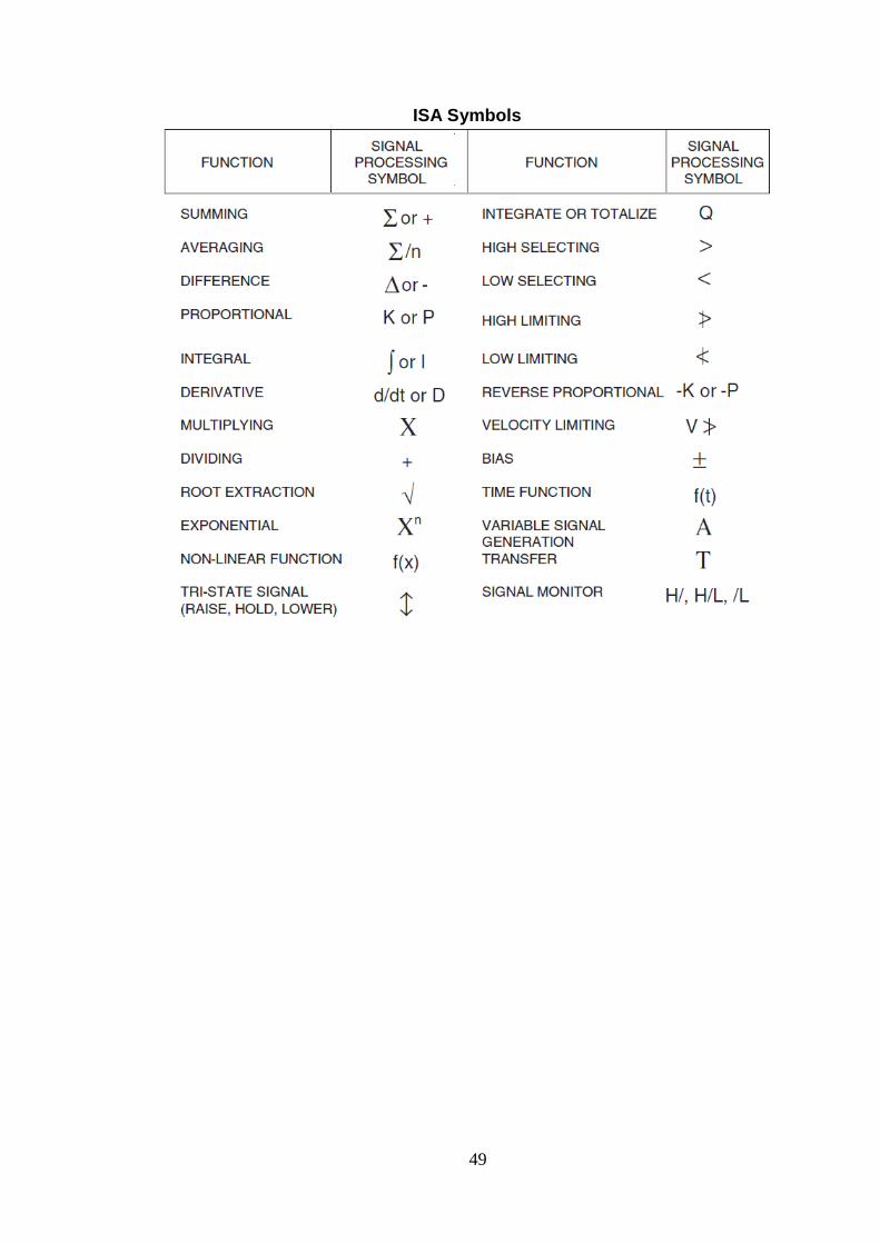
49
ISA Symbols
50
Appendix-IV
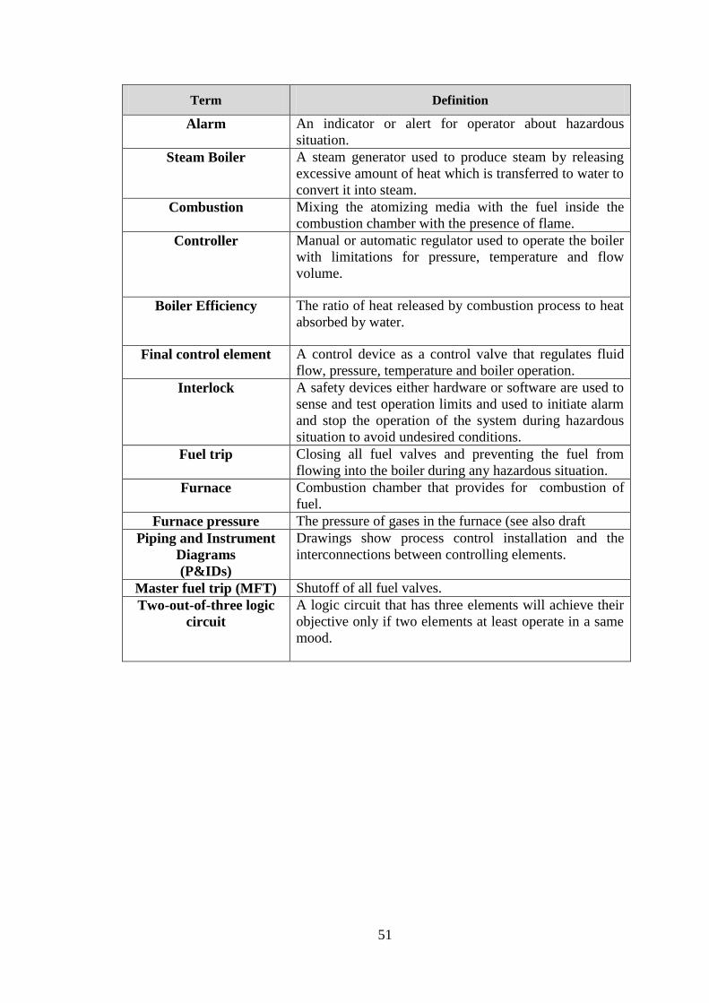
Glossary of Common Boiler Terms
51
Term Definition
Alarm An indicator or alert for operator about hazardous
situation.
Steam Boiler A steam generator used to produce steam by releasing
excessive amount of heat which is transferred to water to
convert it into steam.
Combustion Mixing the atomizing media with the fuel inside the
combustion chamber with the presence of flame.
Controller Manual or automatic regulator used to operate the boiler
with limitations for pressure, temperature and flow
volume.
Boiler Efficiency The ratio of heat released by combustion process to heat
absorbed by water.
Final control element A control device as a control valve that regulates fluid
flow, pressure, temperature and boiler operation.
Interlock A safety devices either hardware or software are used to
sense and test operation limits and used to initiate alarm
and stop the operation of the system during hazardous
situation to avoid undesired conditions.
Fuel trip Closing all fuel valves and preventing the fuel from
flowing into the boiler during any hazardous situation.
Furnace Combustion chamber that provides for combustion of
fuel.
Furnace pressure The pressure of gases in the furnace (see also draft
Piping and Instrument
Diagrams
(P&IDs)
Drawings show process control installation and the
interconnections between controlling elements.
Master fuel trip (MFT) Shutoff of all fuel valves.
Two-out-of-three logic
circuit
A logic circuit that has three elements will achieve their
objective only if two elements at least operate in a same
mood.

52
Appendix-IV
Standards
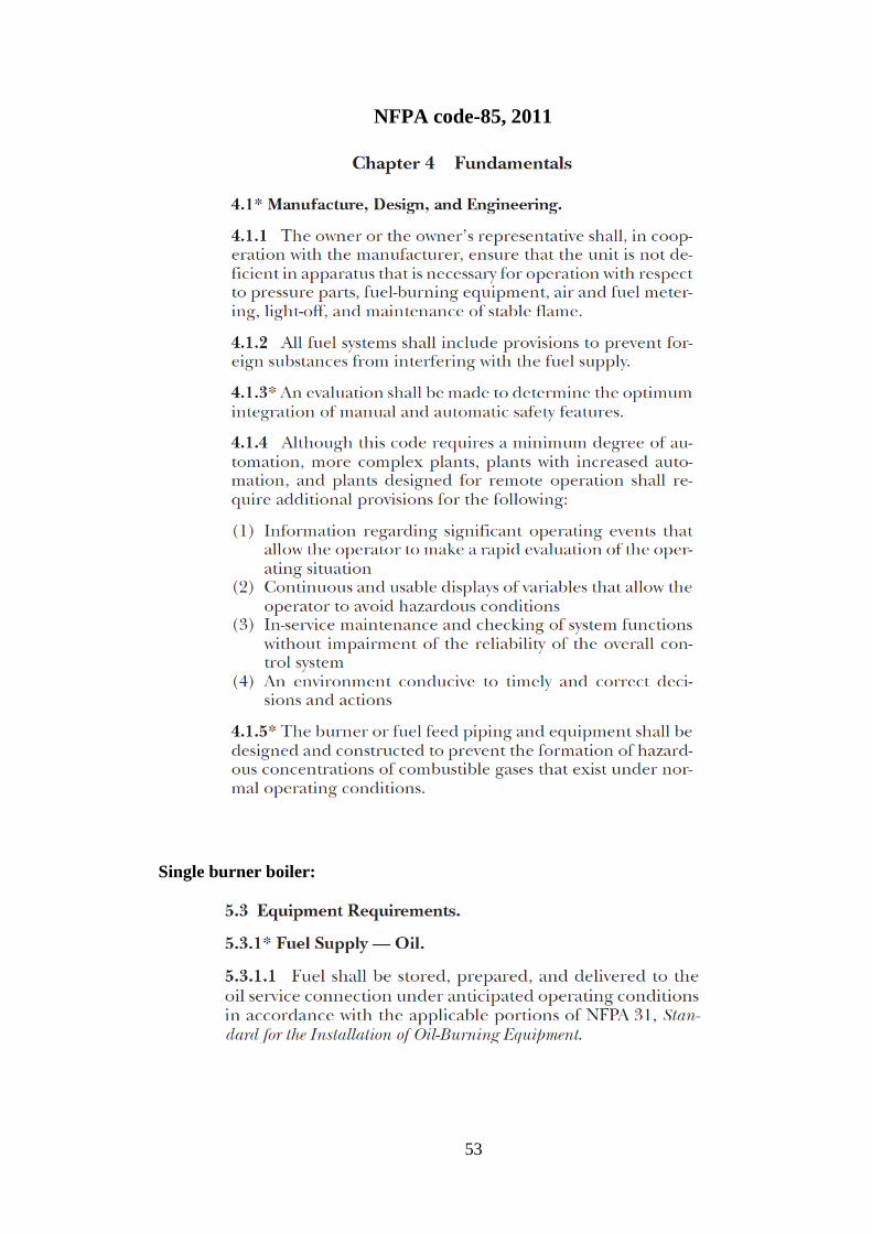
53
NFPA code-85, 2011
Single burner boiler:
54

55
56
57
58
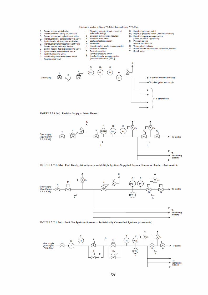
59
60
ASME Boiler and Pressure Vessel Code, 2010
61
62

63
Appendix-V
Awards
64
Awards
The Project was awarded a silver medal in Science and Engineering Design
Exhibition UTP (SEDEX - 31) in August 2013.
Figure 16 SEDEX Certificate


![Climate Safeguard System (CSS) booklet [English]](https://img.pdfslide.us/doc/110x75/568c36591a28ab023597b34d/climate-safeguard-system-css-booklet-english.jpg)