Embed Size (px)
Citation preview

Design of a Permanent Magnet Linear GeneratorHew Wooi Ping, Hamzah Arof, Wijono
Department of Electrical Engineering, University of MalayaKuala Lumpur, Malaysia.
Abstract - This paper present our experience in the design of apermanent magnet generator. The generator has a long translatorand a permanent magnet mover as magnetic field source. Itgenerates a three phase electrical current. The generator isproposed to be operated using a dual chamber free piston internalcombustion linear engine. The finished product is to be placed in ahybrid electric vehicle to generate electricity to run the motorsand to charge the batteries [1],[2].The machine design isperformed using a 2D finite element analysis. The generatorproduces a three phase voltage and the power output is 7 kW.This paper also presents the fabrication of the prototype.
I. INTRODUCTION
Linear generator is an alternative solution in providing anelectrical power supply with high efficiency [3],[4]. Withoutany rotary part in the engine, the machine will be light weightand compact. Prospective applications of this machine are forindustrial, commercial and personal purposes especially wherea stand alone power generation is needed. It is also vital whengrid power utility is unavailable. It can also be used as analternative power generator for hybrid and electric vehicles.
In this paper, design and simulation aspects of a three-phasetubular permanent magnet linear generator intended to bedriven by a free-piston internal combustion engine are outlined.A finite element analysis simulation is used in the generatordesign. A prototype of the machine is fabricated and tested toinvestigate its performance [5].
II. LINEAR GENERATOR DESIGN
A. Generator design selectionThere are two types of linear generator design, i.e. long
translator type and long stator type. In the long translatorgenerator, the translator or mover is longer than the stator, andin the long stator it is vice versa. The translator of a longtranslator type always activates all windings in every generatormotion, on other hand, in the long stator type, only a part ofstator is activated.From the efficiency of the machine point of view, the long
translator generator will be the best choice. The long translatortype is chosen in this design since it has a better performancecompared to long stator machine. The selection of thegenerator type may also depend on the space provided in thegenerator system.
Three types of translator can be noted in the consideration;the moving coil, the moving magnet and the moving iron. Theyall provide magnetic field for the machine coils. In this design,a translator equipped with permanent magnets is considered.
The permanent magnet is used as the magnetic field source
for the machine. It gives a high flux density in the air gapcompared to other translator type for the same volume. It willalso give a translator mass reduction and in turn the moment ofthe translator is also reduced. It is one of the most importantconsiderations in a linear machine design.
In our previous designs axial and radial permanent magnetshad been used [6],[7],[8],[9]. In the axial permanent magnetmachine, a high cogging force is produced due to theinteraction between permanent magnet and stator teeth. Sincethe cogging force becomes a serious problem, radial permanentmagnets is applied to reduce the cogging force. As a result, aquasi Halbach permanent magnet configuration is used [10].This arrangement reduces the translator mass by removing thepermanent magnet back iron used in the radial permanentmagnet machine.
The generator is a three phase electrical power supply. Thethree phase system is chosen since the generator will also beused as a motor in the engine starting mechanism. A singlephase generator will not generate a smooth thrust force when itis operated in the motoring mode.
B. Generator construction and operationThe linear generator system contains a linear electrical
generator and a dual chamber linear internal combustionengine, as shown in the Fig. 1. The engine can be fueled bypetrol or natural gas.
The generator includes a stator and a translator, as shown inthe Fig.2. Two groups of six coils are located in the stator slotto generate a three phase electrical system. The translatormoves forward and backward inside the stator.
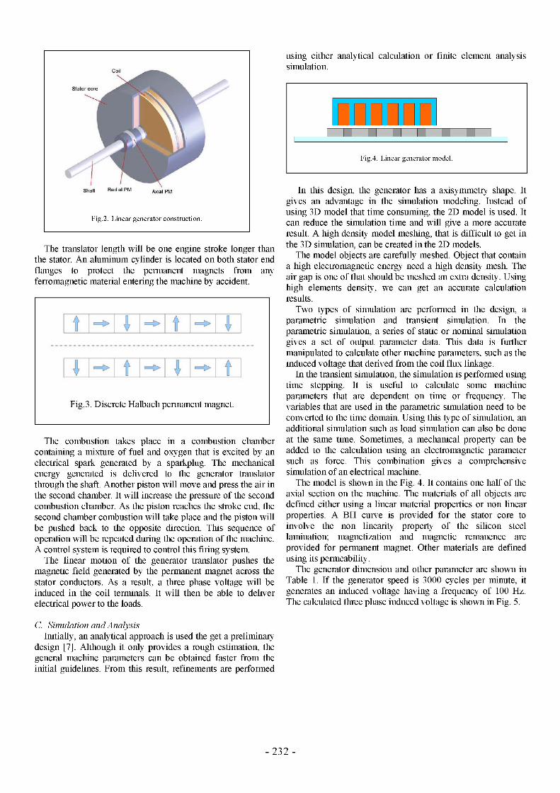
In this machine, seven radial permanent magnets and sixaxial permanent magnets are arranged alternately in a series tobuild a discrete or quasi Halbach permanent magnetarrangement. Fig. 3 shows a discrete or quasi Halbachpermanent magnet arrangement. All the permanent magnets aremounted on an aluminum shaft.
1-4244-0427-4/06/$20.00 ©2006 IEEE
FigE.NEl a gentOR .
Fig.l1. Linear generator.
- 231 - Oct. 18 -Oct. 20, 2006 FOST2006
The translator length will be one engine stroke longer thanthe stator. An aluminum cylinder is located on both stator endflanges to protect the permanent magnets from anyferromagnetic material entering the machine by accident.
The combustion takes place in a combustion chambercontaining a mixture of fuel and oxygen that is excited by an
electrical spark generated by a sparkplug. The mechanicalenergy generated is delivered to the generator translatorthrough the shaft. Another piston will move and press the air inthe second chamber. It will increase the pressure of the secondcombustion chamber. As the piston reaches the stroke end, thesecond chamber combustion will take place and the piston willbe pushed back to the opposite direction. This sequence ofoperation will be repeated during the operation of the machine.A control system is required to control this firing system.
The linear motion of the generator translator pushes themagnetic field generated by the permanent magnet across thestator conductors. As a result, a three phase voltage will beinduced in the coil terminals. It will then be able to deliverelectrical power to the loads.
using either analytical calculation or finite element analysissimulation.
In this design, the generator has a axisymmetry shape. Itgives an advantage in the simulation modeling. Instead ofusing 3D model that time consuming, the 2D model is used. Itcan reduce the simulation time and will give a more accurateresult. A high density model meshing, that is difficult to get inthe 3D simulation, can be created in the 2D models.
The model objects are carefully meshed. Object that containa high electromagnetic energy need a high density mesh. Theair gap is one of that should be meshed an extra density. Usinghigh elements density, we can get an accurate calculationresults.Two types of simulation are performed in the design, a
parametric simulation and transient simulation. In theparametric simulation, a series of static or nominal simulationgives a set of output parameter data. This data is furthermanipulated to calculate other machine parameters, such as theinduced voltage that derived from the coil flux linkage.
In the transient simulation, the simulation is performed usingtime stepping. It is useful to calculate some machineparameters that are dependent on time or frequency. Thevariables that are used in the parametric simulation need to beconverted to the time domain. Using this type of simulation, anadditional simulation such as load simulation can also be doneat the same time. Sometimes, a mechanical property can beadded to the calculation using an electromagnetic parametersuch as force. This combination gives a comprehensivesimulation of an electrical machine.The model is shown in the Fig. 4. It contains one half of the
axial section on the machine. The materials of all objects aredefined either using a linear material properties or non linearproperties. A BH curve is provided for the stator core toinvolve the non linearity property of the silicon steellamination; magnetization and magnetic remanence areprovided for permanent magnet. Other materials are definedusing its permeability.
The generator dimension and other parameter are shown inTable 1. If the generator speed is 3000 cycles per minute, itgenerates an induced voltage having a frequency of 100 Hz.The calculated three phase induced voltage is shown in Fig. 5.
C. Simulation andAnalysisInitially, an analytical approach is used the get a preliminary
design [7]. Although it only provides a rough estimation, thegeneral machine parameters can be obtained faster from theinitial guidelines. From this result, refinements are performed
- 232 -
Stator CTe
hfft Radi:al PM AxIl PMr
Fig.2. Linear generator construction.
Fig.4. Linear generator model.
Fig.3. Discrete Halbach permanent magnet.

Using a wire that has current capacity of 7 Ampere, thegenerator gives a 7 kW output power. In the case that theengine speed is 2000 rpm, the generator will produce a 5 kWoutput power.
Induced Voltage
dl -U-~~~~~~~~~~va0) ~~~~~~~~~~~vb~~~ ~~~~II ~~~~~vc
time (s)
Fig.5. Three phase induced voltage.
III. GENERATOR PROTOTYPE
The generator prototype is shown in the Fig. 6. Thisprototype is ready to run in the linear engine. It is equipped bya cooling system including static fins covering the machinecasing and a liquid cooling system inside the casing. When theheat flowing in the machine is quite low, the cooling fins canemit the heat to the surrounding, but in the case of over heating,the cooling pump should run to deliver the cooling fluid intothe machine. An external control circuit is needed to controlthis mechanism automatically. The shaft may be drilled to letthe air flow for an additional cooling system as far as themechanical properties of its material allows.To protect the permanent magnets, tubular flanges are
placed on the casing. A magnetic displacement sensor is placedon the shaft surface and connected to the control circuit. It isrequired when the generator is operated in motoring mode.
The six coil terminal is mounted on the casing. The external
connection is provided for measurement and three phaseconnection.
Fig.6. Generator Prototype.
IV. FABRICATION
The machine has components that are easy to fabricate andassemble. Excluding permanent magnets, the generatorcomponents can be manufactured in a small workshop. A steelring can be used to combine segmented radial permanentmagnets into a compact construction if the permanent magnetring is unavailable. The ring should be thin avoiding reductionin the magnetic flux. Fig. 7 shows the segmented permanentmagnets arranged into a single ring magnet.
The stator lamination stacking is another problem. A radiallamination stack with axial slot is used. In order to get a rigidconstruction, a special glue is injected to the stator and coilgaps. It is also done to the translator to avoid the vibrationbetween permanent magnets.
V. CONCLUSIONS
- 233 -
TABLE IGENERATOR DIMENTION AND PARAMETERS
Stroke length 69Shaft radius (non ferromagnetic material) 12.5Magnet (axial and radial) inner radius 12.5Radial Magnet length 22.5Radial Magnet thickness 12Axial Magnet length 12Axial Magnet thickness 12Air gap ITooth width 6Stator back iron 6Slot width 17Slot depth 102Wire AWG# 12Number of turn per coil 312
mmmmmmmmmmmmmmmmmmmmmmmm
Fig.7. Ring and segmented permanent magnets.

A 7 kW linear generator has been designed and fabricated. Itis proposed to be driven by a dual chamber internal combustionlinear engine. The design is mainly perforned using finiteelement method to get the accurate results. The generator canbe used as a general purpose ac power source or to producepower for the electrical system in hybrid vehicles.
VI. FUTURE WORK
The further optimization is one of our plans. It includes thefurther investigations on material properties and reduction ofmachine dimensions and machine weight. A practical lineargenerator should have a high power to weight ratio and smallenough to be fitted into a hybrid vehicle.
ACKNOWLEDGMENT
The authors gratefully appreciate and thank the Ministry OfScience, Technology and Environment, Malaysia, for thefunding of this research project under IRPA Grant No.33-02-03-3013.
REFERENCES[1] Jiabin Wang, Member, Ieee, Weiya Wang, Geraint W. Jewell, And David
Howe A Low-Power, Linear, Permanent-Magnet Generator/Energy StorageSystem IEEE Transactions On Industrial Electronics, Vol. 49, No. 3, June2002,pp. 640- 648
[2] Geng, S.M.; Schwarze, G.E.; Niedra, J.M.; A 3-D Magnetic Analysis OfALinear Alternator For A Stirling Power System, Energy ConversionEngineering Conference And Exhibit, 2000. (lecec) 35th IntersocietyVolume 1, 24-28 July 2000 Page(S):232 - 237 Vol.1
[3] William R. Cawthorne, et al, Development of a Linear Alternator-Enginefor Hybrid Electric Vehicle Applications, IEEE TRANSACTIONS ONVEHICULAR TECHNOLOGY, VOL. 48, NO. 6, NOVEMBER 1999, pp.1797- 1802
[4] Famouri, P., Cawthorne, W.R., Clark, N., Nandkumar, S., Atkinson, C.,Atkinson, R., Mcdaniel, T., Petreanu, S., Design And Testing OfA NovelLinear Alternator And Engine System For Remote Electrical PowerGeneration, IEEE Power Engineering Society 1999 Winter Meeting,Volume 1, 31 Jan.-4 Feb. 1999, pp. 108 - 112.
[5] W. P. Hew, J. Jamaludin, M. Tadjuddin, K. M. Nor, 2003, Fabrication andtest of the linear electric generator for a new free piston generator,National Power Engineering Conference, Kuala Lumpur, pg 277-282
[6] H. Arof, Wijono,, K. M. Nor, 2003, Linear generator: design andsimulation, National Power Engineering Conference, Kuala Lumpur, pg306-311
[7] H. Arof, Wijono, and K. M. Nor, Linear Generator: Design and Simulation,in Proc. National Power Engineering Conference (PECon 2003), pp. 306-311, 15-16 December 2003, Bangi, Malaysia.
[8] Khalid Mohamed Nor,Hamzah Arof, and Wijono, Design of a 5 kWTubular Permanent Magnet Linear Generator, in Proc. 39th InternationalUniversities Power Engineering Conference (UPEC 2004), pp. 528-532, 6-8 September 2004, University of the West of England (UWE) Bristol, UK.
[9] Khalid Mohamed Nor, Hamzah Arof, and Wijono, Design of a Three PhaseTubular Permanent Magnet Linear Generator, in Proc. The 5th IASTEDInternational Conference On Power And Energy Systems, EuroPes 2005,15-17 June 2005, Benalmadena, Spain
[10] Jiabin Wang, and David Howe, Tubular Modular Permanent-MagnetMachines Equipped With Quasi-Halbach Magnetized Magnets Part I:Magnetic Field Distribution, EMF, and Thrust Force, IEEE Transactionson Magnetics, Vol. 41, NO. 9, September 2005
[11] Boldea, I.; Nasar, S.A.; Penswick, B.; Ross, B.; Olan, R.;New linearreciprocating machine with stationary permanent magnets IndustryApplications Conference, 1996. Thirty-First IAS Annual Meeting, IAS'96., Conference Record of the 1996 IEEE, Volume 2, 6-10 Oct. 1996Page(s):825 - 829 vol.2
- 234 -