Embed Size (px)
Citation preview
Application Note AC387
Designing Radiation-Tolerant Power-Supplies for the RTAX-S/SL/DSP FPGA
Table of Contents
IntroductionSystem engineers who design products that need to be Radiation-Tolerant (such as Satellites,Gyroscopes, Rocket-Launchers, all Deep-Space missions, etc) are faced with some unique challenges.
Few Specialized VendorsRadiation-Tolerant semiconductor products are available from very few vendors than commercial throughmilitary grade components. As a further restriction, most semiconductor manufacturers only offer a fewtypes of products (relays, for example). System engineers often have to select different types ofcomponents from different vendors (for example, a Field Programmable Gate Array (FPGA) fromMicrosemi®, a Power-Supply from Vendor#2, a Regulator from Vendor#3, etc).
Functional and Radiation Test SpecificationsEvery semiconductor manufacturer does electrical tests, including radiation-tolerance testing slightlydifferently and therefore each component's specifications are slightly different (behaviorally, electrically,and radiation-tolerance wise).
As a result, the system engineers designing a system also have an additional burden and risk. Theyneed to select various types of components-all tested and specified at different test levels and standardsfrom the other components they selected-with the goal that they must or should work together.
Microsemi manufactures and provides many Radiation-Tolerant components that work-together, so the system engineer can confidently select components from one semiconductorvendor which will all work together.
This application note describes how the engineers design a Microsemi Radiation-Tolerant FPGAconfidently. This FPGA helps in performing the following:
1. Calculate required power of the RTAX-S FPGA1
2. Select an appropriate Radiation-Tolerant regulator that can supply the required power and meetall the unique power-requirements of the FPGA, using either of the below given:
– Radiation-Tolerant Linear-Regulator (Microsemi) or
– Radiation-Tolerant Switching regulator (Microsemi)
3. Select an appropriate Radiation-Tolerant Power-Supply (Microsemi)
Introduction . . . . . . . . . . . . . . . . . . . . . . . . . . . . . . . . . . . . . . . . . . . . . . . . 1RTAX-S Basic Information on the RTAX-S Device . . . . . . . . . . . . . . . . . . . . . . . . . . . . 2Calculating Required Power of the Radiation-Tolerant RTAX-S FPGA . . . . . . . . . . . . . . . . . . 3Power-Supply Solutions to Power the RTAX-S FPGA . . . . . . . . . . . . . . . . . . . . . . . . . . 5Summary . . . . . . . . . . . . . . . . . . . . . . . . . . . . . . . . . . . . . . . . . . . . . . . . 13
1. All references to RTAX-S FPGA Family include the RTAX-S Family, and RTAX-SL (RTAX-S Family in a Low-Powerversion), and RTAX-DSP (RTAX-S with internal hardcoder DSP (Digital Signal Processing) blocks).
September 2012 1
© 2012 Microsemi Corporation
Designing Radiation-Tolerant Power-Supplies for the RTAX-S/SL/DSP FPGA
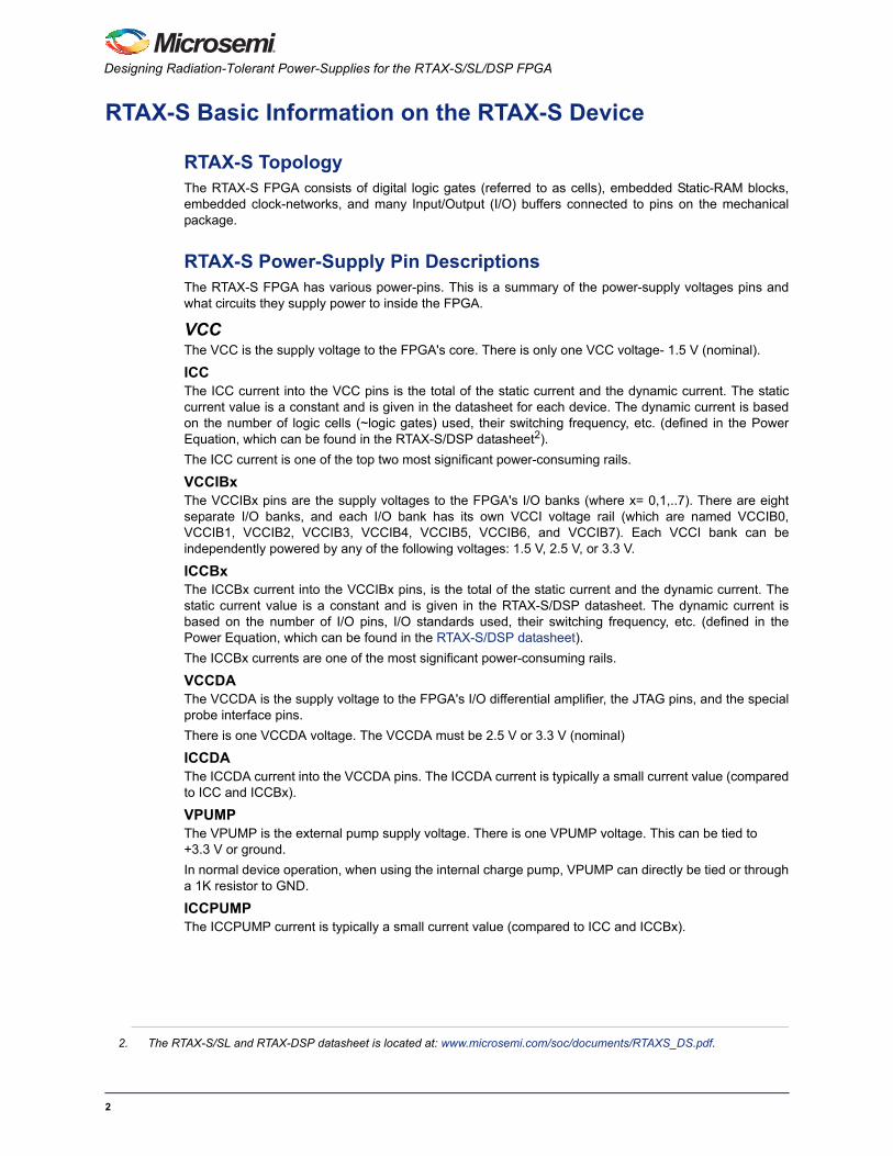
RTAX-S Basic Information on the RTAX-S Device
RTAX-S TopologyThe RTAX-S FPGA consists of digital logic gates (referred to as cells), embedded Static-RAM blocks,embedded clock-networks, and many Input/Output (I/O) buffers connected to pins on the mechanicalpackage.
RTAX-S Power-Supply Pin DescriptionsThe RTAX-S FPGA has various power-pins. This is a summary of the power-supply voltages pins andwhat circuits they supply power to inside the FPGA.
VCCThe VCC is the supply voltage to the FPGA's core. There is only one VCC voltage- 1.5 V (nominal).
ICCThe ICC current into the VCC pins is the total of the static current and the dynamic current. The staticcurrent value is a constant and is given in the datasheet for each device. The dynamic current is basedon the number of logic cells (~logic gates) used, their switching frequency, etc. (defined in the PowerEquation, which can be found in the RTAX-S/DSP datasheet2).
The ICC current is one of the top two most significant power-consuming rails.
VCCIBxThe VCCIBx pins are the supply voltages to the FPGA's I/O banks (where x= 0,1,..7). There are eightseparate I/O banks, and each I/O bank has its own VCCI voltage rail (which are named VCCIB0,VCCIB1, VCCIB2, VCCIB3, VCCIB4, VCCIB5, VCCIB6, and VCCIB7). Each VCCI bank can beindependently powered by any of the following voltages: 1.5 V, 2.5 V, or 3.3 V.
ICCBxThe ICCBx current into the VCCIBx pins, is the total of the static current and the dynamic current. Thestatic current value is a constant and is given in the RTAX-S/DSP datasheet. The dynamic current isbased on the number of I/O pins, I/O standards used, their switching frequency, etc. (defined in thePower Equation, which can be found in the RTAX-S/DSP datasheet).
The ICCBx currents are one of the most significant power-consuming rails.
VCCDAThe VCCDA is the supply voltage to the FPGA's I/O differential amplifier, the JTAG pins, and the specialprobe interface pins.
There is one VCCDA voltage. The VCCDA must be 2.5 V or 3.3 V (nominal)
ICCDAThe ICCDA current into the VCCDA pins. The ICCDA current is typically a small current value (comparedto ICC and ICCBx).
VPUMPThe VPUMP is the external pump supply voltage. There is one VPUMP voltage. This can be tied to +3.3 V or ground.
In normal device operation, when using the internal charge pump, VPUMP can directly be tied or througha 1K resistor to GND.
ICCPUMPThe ICCPUMP current is typically a small current value (compared to ICC and ICCBx).
2. The RTAX-S/SL and RTAX-DSP datasheet is located at: www.microsemi.com/soc/documents/RTAXS_DS.pdf.
2
Calculating Required Power of the Radiation-Tolerant RTAX-S FPGA
RTAX-S Power-Consumption ComponentsThe Power-Consumption of the RTAX-S FPGA is the sum of two types of power components: staticpower and dynamic power.
• Static power-consumption is a constant value for each device in the RTAX-S FPGA family and isa sum of the individual static power values for each power-rail of the FPGA. The static power-consumption value is provided in the datasheet for each device. Low power version of theRTAX-S/DSP FPGA's are available, which have lower standby-current, that is up to 80% lessthan the standard RTAX-S FPGA.
• Dynamic power-consumption values are a function of the design that is implemented in theFPGA. This value is highly design-dependent. This value is based on the number of logic cells(~logic gates) used and their switching frequency, number of I/O pins and their switchingfrequency, I/O standards used, the load on the I/O pins, temperature, voltage, etc.
Since the power-consumption of the RTAX-S FPGA is highly dependent on the digital design that isimplemented inside of it, the power-consumption needs to be calculated for each individual design that isimplemented inside the FPGA.
Dynamic power is the major part in the total power-consumption of a typical RTAX-S FPGA.
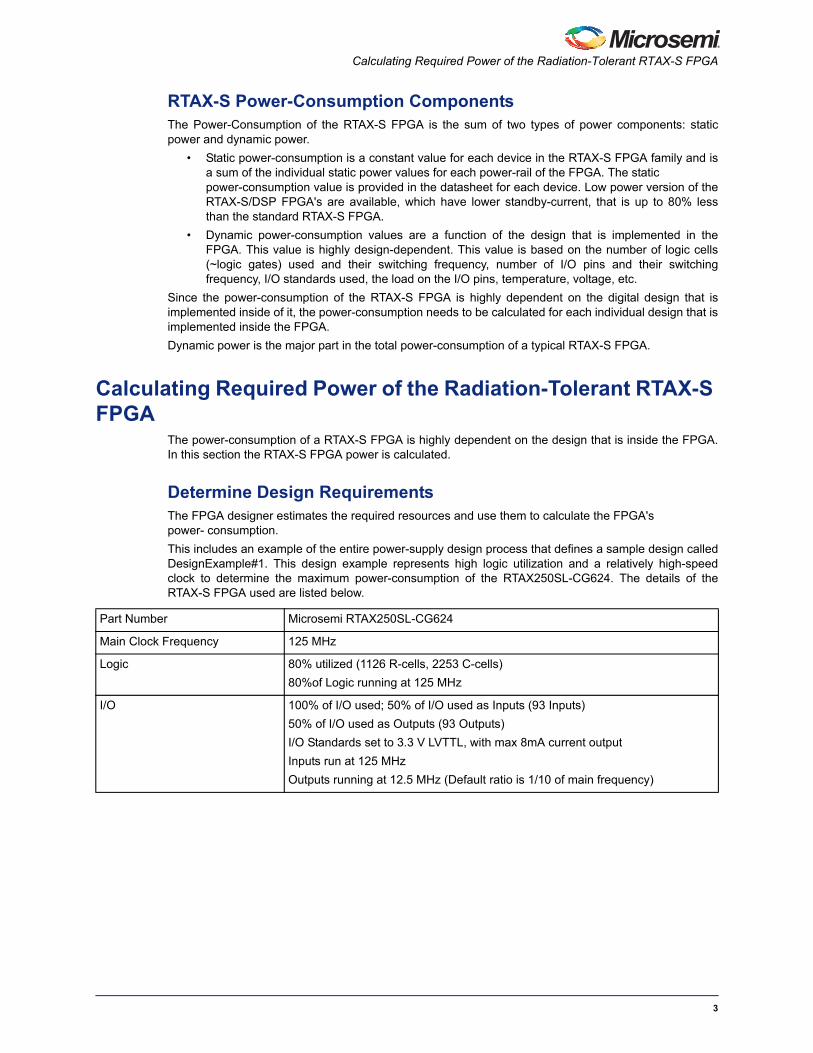
Calculating Required Power of the Radiation-Tolerant RTAX-S FPGA
The power-consumption of a RTAX-S FPGA is highly dependent on the design that is inside the FPGA.In this section the RTAX-S FPGA power is calculated.
Determine Design RequirementsThe FPGA designer estimates the required resources and use them to calculate the FPGA's power- consumption.
This includes an example of the entire power-supply design process that defines a sample design calledDesignExample#1. This design example represents high logic utilization and a relatively high-speedclock to determine the maximum power-consumption of the RTAX250SL-CG624. The details of theRTAX-S FPGA used are listed below.
Part Number Microsemi RTAX250SL-CG624
Main Clock Frequency 125 MHz
Logic 80% utilized (1126 R-cells, 2253 C-cells)
80%of Logic running at 125 MHz
I/O 100% of I/O used; 50% of I/O used as Inputs (93 Inputs)
50% of I/O used as Outputs (93 Outputs)
I/O Standards set to 3.3 V LVTTL, with max 8mA current output
Inputs run at 125 MHz
Outputs running at 12.5 MHz (Default ratio is 1/10 of main frequency)
3
Designing Radiation-Tolerant Power-Supplies for the RTAX-S/SL/DSP FPGA
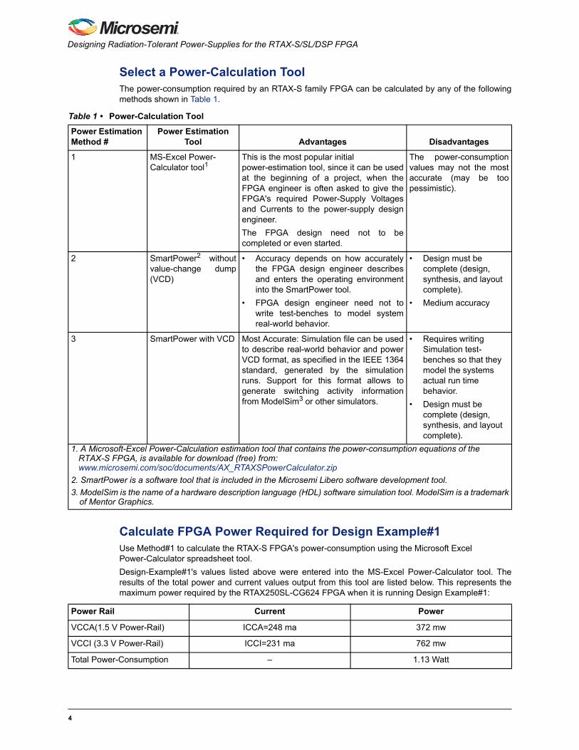
Select a Power-Calculation ToolThe power-consumption required by an RTAX-S family FPGA can be calculated by any of the followingmethods shown in Table 1.
Calculate FPGA Power Required for Design Example#1Use Method#1 to calculate the RTAX-S FPGA's power-consumption using the Microsoft Excel Power-Calculator spreadsheet tool.
Design-Example#1's values listed above were entered into the MS-Excel Power-Calculator tool. Theresults of the total power and current values output from this tool are listed below. This represents themaximum power required by the RTAX250SL-CG624 FPGA when it is running Design Example#1:
Table 1 • Power-Calculation Tool
Power Estimation Method #
Power Estimation Tool Advantages Disadvantages
1 MS-Excel Power-Calculator tool1
This is the most popular initial power-estimation tool, since it can be usedat the beginning of a project, when theFPGA engineer is often asked to give theFPGA's required Power-Supply Voltagesand Currents to the power-supply designengineer.
The FPGA design need not to becompleted or even started.
The power-consumptionvalues may not the mostaccurate (may be toopessimistic).
2 SmartPower2 withoutvalue-change dump(VCD)
• Accuracy depends on how accuratelythe FPGA design engineer describesand enters the operating environmentinto the SmartPower tool.
• FPGA design engineer need not towrite test-benches to model systemreal-world behavior.
• Design must be complete (design, synthesis, and layout complete).
• Medium accuracy
3 SmartPower with VCD Most Accurate: Simulation file can be usedto describe real-world behavior and powerVCD format, as specified in the IEEE 1364standard, generated by the simulationruns. Support for this format allows togenerate switching activity informationfrom ModelSim3 or other simulators.
• Requires writing Simulation test-benches so that they model the systems actual run time behavior.
• Design must be complete (design, synthesis, and layout complete).
1. A Microsoft-Excel Power-Calculation estimation tool that contains the power-consumption equations of the RTAX-S FPGA, is available for download (free) from: www.microsemi.com/soc/documents/AX_RTAXSPowerCalculator.zip
2. SmartPower is a software tool that is included in the Microsemi Libero software development tool.
3. ModelSim is the name of a hardware description language (HDL) software simulation tool. ModelSim is a trademarkof Mentor Graphics.
Power Rail Current Power
VCCA(1.5 V Power-Rail) ICCA=248 ma 372 mw
VCCI (3.3 V Power-Rail) ICCI=231 ma 762 mw
Total Power-Consumption – 1.13 Watt
4
Power-Supply Solutions to Power the RTAX-S FPGA
Check that FPGA Power (DesignExample#1) Does Not Exceed the Thermal Power-Dissipation LimitIn this section, calculate the maximum power that the CG624 package can thermally dissipate. Check ifthe design that is implemented in the RTAX-S FPGA (use DesignExample#1) is less than the maximumpower that the package can dissipate.
Note: In the space environment there is no air, so the FPGA must be conduction-cooled. In a spacecraft,there are thermal cooling systems. In this example, the spacecraft cooling system would cool acooling plate that is thermally conducting and transferring heat from CG624 mechanical package.While calculating the maximum power dissipation, it is required to use the equation that is based onthermal cooling from the case of the FPGA to the junction of the FPGA.
Use the following definitions to describe the environment:
• T_board=50°C: This is the PC-board cooling-plate temperature
• Theta_Case_to_Board, the thermal resistance of thermal paste is 0.58C/Watt
• Theta_JC, the thermal resistance for RTAX250SL in CG624 is 4.6C/Watt
EQ 1
EQ 2
EQ 3
Since the maximum power dissipation of the FPGA from DesignExample#1 (consumes 1.14 Watt) is lessthan the maximum power allowed that the CG624 can dissipate (14.47 Watts) in the environmentdescribed above. The CG624 package can dissipate the entire power of DesignExample#1.
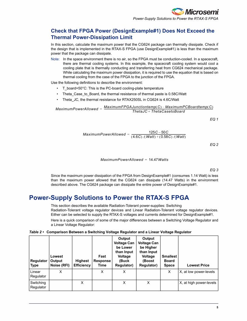
Power-Supply Solutions to Power the RTAX-S FPGAThis section describes the available Radiation-Tolerant power-supplies: Switching Radiation-Tolerant voltage regulator devices and Linear Radiation-Tolerant voltage regulator devices.Either can be selected to supply the RTAX-S voltages and currents determined for DesignExample#1.
Here is a quick comparison of some of the major differences between a Switching Voltage Regulator anda Linear Voltage Regulator:
MaximumPowerAllowedMaximumFPGAJunctiontemp C MaximumPCBoardtemp C –
ThetaJC ThetaCasetoBoard+------------------------------------------------------------------------------------------------------------------------------------------------------------------------------------=
MaximumPowerAllowed125C 50C–
4.6C Watt 0.58C Watt +------------------------------------------------------------------------------------------=
MaximumPowerAllowed 14.47Watts=
Table 2 • Comparison Between a Switching Voltage Regulator and a Linear Voltage Regulator
Regulator Type
Lowest Output Noise (RFI)
Highest Efficiency
Fast Response
Time
Output Voltage Can
be Lower than Input
Voltage (Buck
Regulator)
Output Voltage Can be Higher than Input
Voltage (Boost
Regulator)
Smallest Board Space Lowest Price
LinearRegulator
X X X X X, at low power-levels
SwitchingRegulator
X X X X, at high power-levels
5
Designing Radiation-Tolerant Power-Supplies for the RTAX-S/SL/DSP FPGA
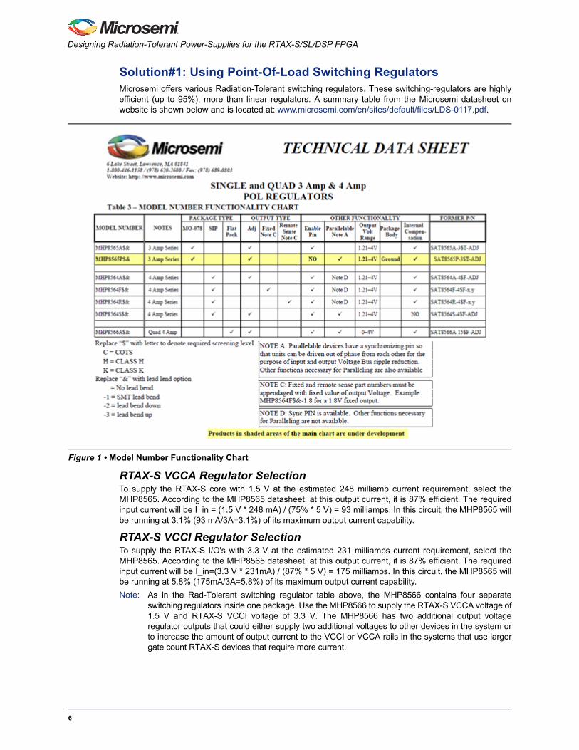
Solution#1: Using Point-Of-Load Switching RegulatorsMicrosemi offers various Radiation-Tolerant switching regulators. These switching-regulators are highlyefficient (up to 95%), more than linear regulators. A summary table from the Microsemi datasheet onwebsite is shown below and is located at: www.microsemi.com/en/sites/default/files/LDS-0117.pdf.
RTAX-S VCCA Regulator SelectionTo supply the RTAX-S core with 1.5 V at the estimated 248 milliamp current requirement, select theMHP8565. According to the MHP8565 datasheet, at this output current, it is 87% efficient. The requiredinput current will be I_in = (1.5 V * 248 mA) / (75% * 5 V) = 93 milliamps. In this circuit, the MHP8565 willbe running at 3.1% (93 mA/3A=3.1%) of its maximum output current capability.
RTAX-S VCCI Regulator SelectionTo supply the RTAX-S I/O's with 3.3 V at the estimated 231 milliamps current requirement, select theMHP8565. According to the MHP8565 datasheet, at this output current, it is 87% efficient. The requiredinput current will be I_in=(3.3 V * 231mA) / (87% * 5 V) = 175 milliamps. In this circuit, the MHP8565 willbe running at 5.8% (175mA/3A=5.8%) of its maximum output current capability.
Note: As in the Rad-Tolerant switching regulator table above, the MHP8566 contains four separateswitching regulators inside one package. Use the MHP8566 to supply the RTAX-S VCCA voltage of1.5 V and RTAX-S VCCI voltage of 3.3 V. The MHP8566 has two additional output voltageregulator outputs that could either supply two additional voltages to other devices in the system orto increase the amount of output current to the VCCI or VCCA rails in the systems that use largergate count RTAX-S devices that require more current.
Figure 1 • Model Number Functionality Chart
6
Power-Supply Solutions to Power the RTAX-S FPGA
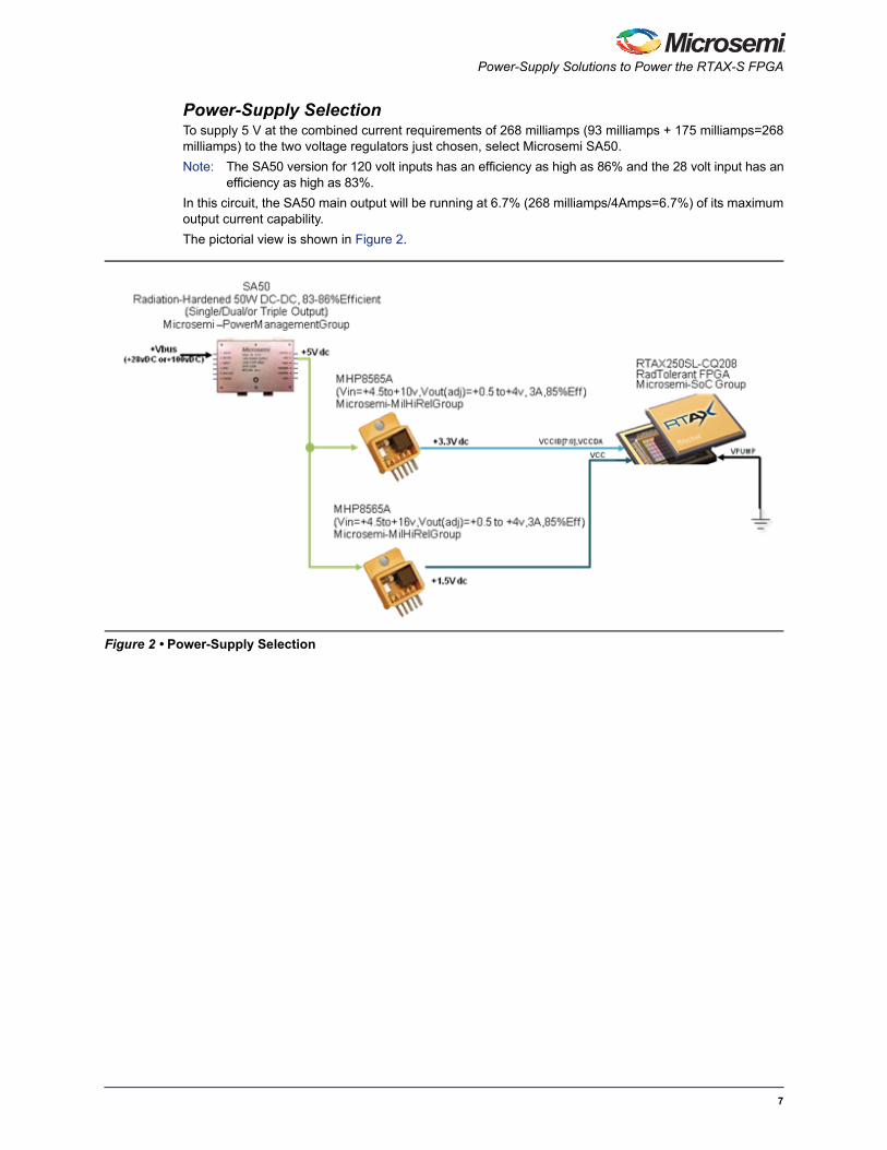
Power-Supply SelectionTo supply 5 V at the combined current requirements of 268 milliamps (93 milliamps + 175 milliamps=268milliamps) to the two voltage regulators just chosen, select Microsemi SA50.
Note: The SA50 version for 120 volt inputs has an efficiency as high as 86% and the 28 volt input has anefficiency as high as 83%.
In this circuit, the SA50 main output will be running at 6.7% (268 milliamps/4Amps=6.7%) of its maximumoutput current capability.
The pictorial view is shown in Figure 2.
Figure 2 • Power-Supply Selection
7
Designing Radiation-Tolerant Power-Supplies for the RTAX-S/SL/DSP FPGA
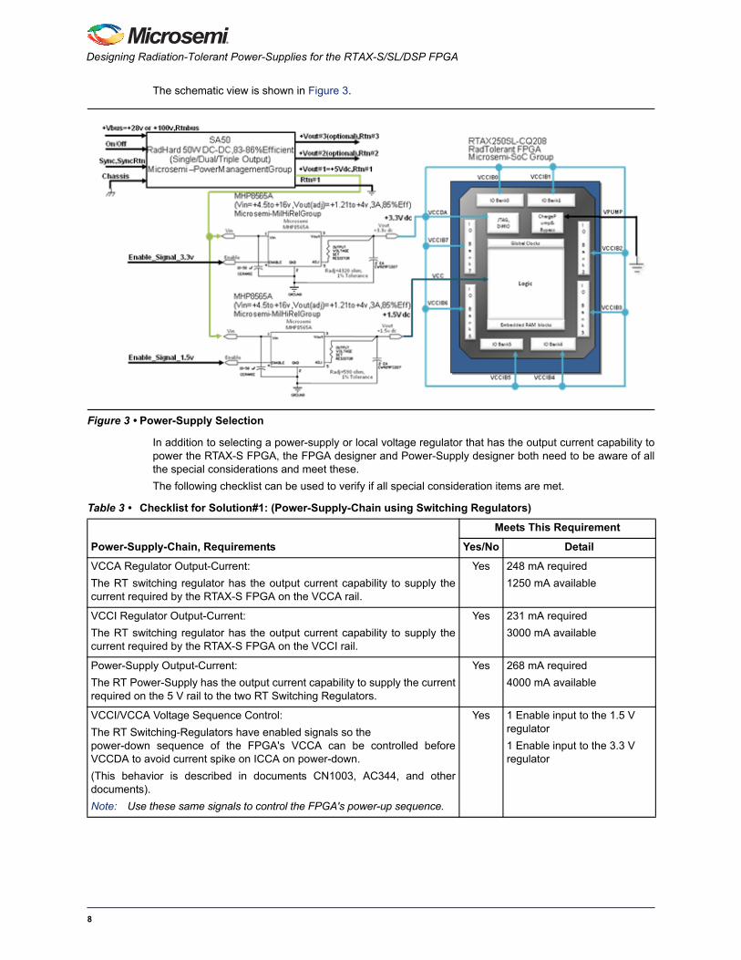
The schematic view is shown in Figure 3.
In addition to selecting a power-supply or local voltage regulator that has the output current capability topower the RTAX-S FPGA, the FPGA designer and Power-Supply designer both need to be aware of allthe special considerations and meet these.
The following checklist can be used to verify if all special consideration items are met.
Figure 3 • Power-Supply Selection
Table 3 • Checklist for Solution#1: (Power-Supply-Chain using Switching Regulators)
Power-Supply-Chain, Requirements
Meets This Requirement
Yes/No Detail
VCCA Regulator Output-Current:
The RT switching regulator has the output current capability to supply thecurrent required by the RTAX-S FPGA on the VCCA rail.
Yes 248 mA required
1250 mA available
VCCI Regulator Output-Current:
The RT switching regulator has the output current capability to supply thecurrent required by the RTAX-S FPGA on the VCCI rail.
Yes 231 mA required
3000 mA available
Power-Supply Output-Current:
The RT Power-Supply has the output current capability to supply the currentrequired on the 5 V rail to the two RT Switching Regulators.
Yes 268 mA required
4000 mA available
VCCI/VCCA Voltage Sequence Control:
The RT Switching-Regulators have enabled signals so the power-down sequence of the FPGA's VCCA can be controlled beforeVCCDA to avoid current spike on ICCA on power-down.
(This behavior is described in documents CN1003, AC344, and otherdocuments).
Note: Use these same signals to control the FPGA's power-up sequence.
Yes 1 Enable input to the 1.5 V regulator
1 Enable input to the 3.3 V regulator
8
Power-Supply Solutions to Power the RTAX-S FPGA
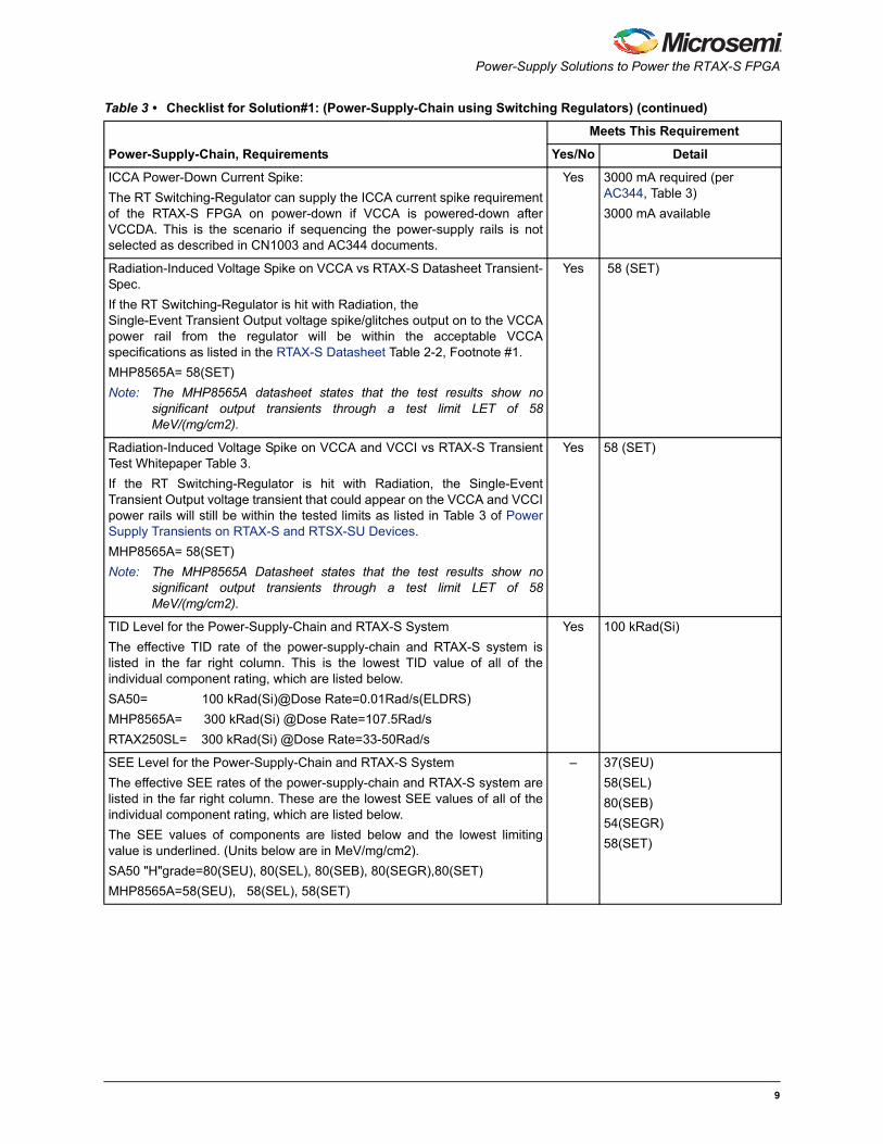
ICCA Power-Down Current Spike:
The RT Switching-Regulator can supply the ICCA current spike requirementof the RTAX-S FPGA on power-down if VCCA is powered-down afterVCCDA. This is the scenario if sequencing the power-supply rails is notselected as described in CN1003 and AC344 documents.
Yes 3000 mA required (per AC344, Table 3)
3000 mA available
Radiation-Induced Voltage Spike on VCCA vs RTAX-S Datasheet Transient-Spec.
If the RT Switching-Regulator is hit with Radiation, the Single-Event Transient Output voltage spike/glitches output on to the VCCApower rail from the regulator will be within the acceptable VCCAspecifications as listed in the RTAX-S Datasheet Table 2-2, Footnote #1.
MHP8565A= 58(SET)
Note: The MHP8565A datasheet states that the test results show nosignificant output transients through a test limit LET of 58MeV/(mg/cm2).
Yes 58 (SET)
Radiation-Induced Voltage Spike on VCCA and VCCI vs RTAX-S TransientTest Whitepaper Table 3.
If the RT Switching-Regulator is hit with Radiation, the Single-EventTransient Output voltage transient that could appear on the VCCA and VCCIpower rails will still be within the tested limits as listed in Table 3 of PowerSupply Transients on RTAX-S and RTSX-SU Devices.
MHP8565A= 58(SET)
Note: The MHP8565A Datasheet states that the test results show nosignificant output transients through a test limit LET of 58MeV/(mg/cm2).
Yes 58 (SET)
TID Level for the Power-Supply-Chain and RTAX-S System
The effective TID rate of the power-supply-chain and RTAX-S system islisted in the far right column. This is the lowest TID value of all of theindividual component rating, which are listed below.
SA50= 100 kRad(Si)@Dose Rate=0.01Rad/s(ELDRS)
MHP8565A= 300 kRad(Si) @Dose Rate=107.5Rad/s
RTAX250SL= 300 kRad(Si) @Dose Rate=33-50Rad/s
Yes 100 kRad(Si)
SEE Level for the Power-Supply-Chain and RTAX-S System
The effective SEE rates of the power-supply-chain and RTAX-S system arelisted in the far right column. These are the lowest SEE values of all of theindividual component rating, which are listed below.
The SEE values of components are listed below and the lowest limitingvalue is underlined. (Units below are in MeV/mg/cm2).
SA50 "H"grade=80(SEU), 80(SEL), 80(SEB), 80(SEGR),80(SET)
MHP8565A=58(SEU), 58(SEL), 58(SET)
– 37(SEU)
58(SEL)
80(SEB)
54(SEGR)
58(SET)
Table 3 • Checklist for Solution#1: (Power-Supply-Chain using Switching Regulators) (continued)
Power-Supply-Chain, Requirements
Meets This Requirement
Yes/No Detail
9
Designing Radiation-Tolerant Power-Supplies for the RTAX-S/SL/DSP FPGA
Solution#2: Using Point-Of-Load Linear RegulatorsMicrosemi offers various Radiation-Tolerant Linear Regulators and the efficiency of the linear regulatordepends on the input and output voltages involved. The summary table is on page 4 in the catalog isshown below and is located at:
www.microsemi.com/en/sites/default/files/datasheets/Microsemi_Hybrid_Products.pdf
Use of the MHL8701/8705 SET-free regulator is recommended. The MHL8701/8705 is a SET-free LinearRegulator version of the previous MHL8601/8605.
RTAX-S VCCA Regulator SelectionTo supply the RTAX-S Core with 1.5 V at the estimated 248 milliamps current requirement, select theMHL8705. At an output current of 248 milliamps, the input current will also be approximately 248milliamps. In this circuit, the MHL8705 will be running at 5.0% (248mA/5.0Amp= 5.0%) of its maximumoutput current capability.
RTAX-S VCCI Regulator SelectionTo supply the RTAX-S I/O with 3.3 V at the estimated 231 milliamps current requirement, select theMHL8701. The input current will also be approximately 231 milliamps. In this circuit, the MHL8701 will berunning at 7.7% (231mA/3.0 Amp= 7.7%) of its maximum output current capability.
Power-Supply SelectionTo supply 5 V at the combined current requirements of 479 milliamps (248 milliamps + 231 milliamp=479milliamps), to supply power to the selected two voltage regulators, select Microsemi SA50.
Note: The SA50 version for 120 V inputs has an efficiency as high as 86% and the 28 V input has anefficiency as high as 83%.
In this circuit, the SA50 main output will be running at 12.0% (479 milliamps/4Amps= 12.0%) of itsmaximum output current capability.
The pictorial view is shown in Figure 4 on page 11.
Table 4 • Checklist for Solution#1: (Power-Supply-Chain using SWITCHING Regulators)
Part Description Critical Parameters Packages
8601 Pos., Linear, 3A, Fixed & Adj VlDO=0.300 V (3A), (5A), Rad-Hardto 300Krad+
5 Pin MO-078
8605R Pos., Linear, 5A, Fixed w/Remote Sense
VLDO=0.300 V (3A), 0.400 V (5A)Rad-Hard to 300Krad+
5- Pin MO-078, 8-Pin SMT
117 Pos., Linear, Adj., 1.25A, Vin=40 V Rad-Hard to 300Krad D2
127 Dual, 1A, Pos. & Neg.Linear regulator
Rad-Hard to 300 Krad 8-Pin, TO-254
10
Power-Supply Solutions to Power the RTAX-S FPGA
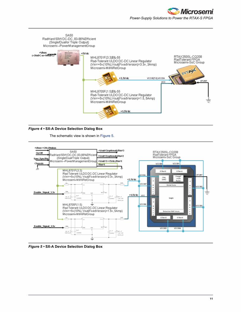
The schematic view is shown in Figure 5.
Figure 4 • SX-A Device Selection Dialog Box
Figure 5 • SX-A Device Selection Dialog Box
11
Designing Radiation-Tolerant Power-Supplies for the RTAX-S/SL/DSP FPGA
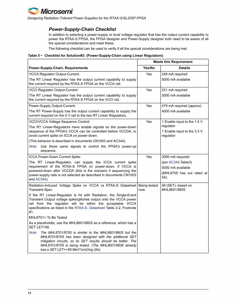
Power-Supply-Chain ChecklistIn addition to selecting a power-supply or local voltage regulator that has the output current capability topower the RTAX-S FPGA, the FPGA designer and Power-Supply designer both need to be aware of allthe special considerations and meet these.
The following checklist can be used to verify if all the special considerations are being met.
Table 5 • Checklist for Solution#2: (Power-Supply-Chain using Linear Regulators)
Power-Supply-Chain, Requirements
Meets this Requirement
Yes/No Details
VCCA Regulator Output-Current:
The RT Linear Regulator has the output current capability to supplythe current required by the RTAX-S FPGA on the VCCA rail.
Yes 248 mA required
5000 mA available
VCCI Regulator Output-Current:
The RT Linear Regulator has the output current capability to supplythe current required by the RTAX-S FPGA on the VCCI rail.
Yes 231 mA required
3000 mA available
Power-Supply Output-Current:
The RT Power-Supply has the output current capability to supply thecurrent required on the 5 V rail to the two RT Linear Regulators.
Yes 479 mA required (approx)
4000 mA available
VCCI/VCCA Voltage Sequence Control:
The RT Linear-Regulators have enable signals so the power-downsequence of the FPGA's VCCA can be controlled before VCCDA, toavoid current spike on ICCA on power-down.
(This behavior is described in documents CN1003 and AC344).
Note: Use these same signals to control the FPGA's power-upsequence.
Yes 1 Enable input to the 1.5 V regulator
1 Enable input to the 3.3 V regulator
ICCA Power-Down Current Spike:
The RT Linear-Regulator, can supply the ICCA current spikerequirement of the RTAX-S FPGA on power-down, if VCCA ispowered-down after VCCDA (this is the scenario if sequencing thepower-supply rails is not selected as described in documents CN1003and AC344).
Yes 3000 mA required
(per AC344,Table3)
5000 mA available
(MHL8705 has out rated at5A)
Radiation-Induced Voltage Spike on VCCA vs RTAX-S DatasheetTransient-Spec
If the RT Linear-Regulator is hit with Radiation, the Single-EventTransient Output voltage spike/glitches output onto the VCCA powerrail from the regulator will be within the acceptable VCCAspecifications as listed in the RTAX-S- Datasheet Table 2-2, Footnote#1.
MHL8701= To Be Tested
As a placeholder, use the MHL8601/8605 as a reference, which has aSET LET=58.
Note: The MHL8701/8705 is similar to the MHL8601/8605 but theMHL8701/8705 has been designed with the additional SETmitigation circuits, so its SET results should be better. TheMHL8701/8705 is being tested. (The MHL8601/8606 alreadyhas a SET LET>=58 MeV*cm2/mg (Xe).
Being tested now
58 (SET), based on MHL8601/8605
12
Summary
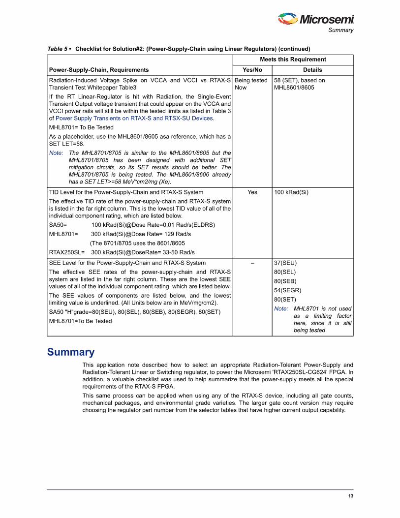
SummaryThis application note described how to select an appropriate Radiation-Tolerant Power-Supply andRadiation-Tolerant Linear or Switching regulator, to power the Microsemi 'RTAX250SL-CG624' FPGA. Inaddition, a valuable checklist was used to help summarize that the power-supply meets all the specialrequirements of the RTAX-S FPGA.
This same process can be applied when using any of the RTAX-S device, including all gate counts,mechanical packages, and environmental grade varieties. The larger gate count version may requirechoosing the regulator part number from the selector tables that have higher current output capability.
Radiation-Induced Voltage Spike on VCCA and VCCI vs RTAX-STransient Test Whitepaper Table3
If the RT Linear-Regulator is hit with Radiation, the Single-EventTransient Output voltage transient that could appear on the VCCA andVCCI power rails will still be within the tested limits as listed in Table 3of Power Supply Transients on RTAX-S and RTSX-SU Devices.
MHL8701= To Be Tested
As a placeholder, use the MHL8601/8605 asa reference, which has aSET LET=58.
Note: The MHL8701/8705 is similar to the MHL8601/8605 but theMHL8701/8705 has been designed with additional SETmitigation circuits, so its SET results should be better. TheMHL8701/8705 is being tested. The MHL8601/8606 alreadyhas a SET LET>=58 MeV*cm2/mg (Xe).
Being tested Now
58 (SET), based on MHL8601/8605
TID Level for the Power-Supply-Chain and RTAX-S System
The effective TID rate of the power-supply-chain and RTAX-S systemis listed in the far right column. This is the lowest TID value of all of theindividual component rating, which are listed below.
SA50= 100 kRad(Si)@Dose Rate=0.01 Rad/s(ELDRS)
MHL8701= 300 kRad(Si)@Dose Rate= 129 Rad/s
(The 8701/8705 uses the 8601/8605
RTAX250SL= 300 kRad(Si)@DoseRate= 33-50 Rad/s
Yes 100 kRad(Si)
SEE Level for the Power-Supply-Chain and RTAX-S System
The effective SEE rates of the power-supply-chain and RTAX-Ssystem are listed in the far right column. These are the lowest SEEvalues of all of the individual component rating, which are listed below.
The SEE values of components are listed below, and the lowestlimiting value is underlined. (All Units below are in MeV/mg/cm2).
SA50 "H"grade=80(SEU), 80(SEL), 80(SEB), 80(SEGR), 80(SET)
MHL8701=To Be Tested
– 37(SEU)
80(SEL)
80(SEB)
54(SEGR)
80(SET)
Note: MHL8701 is not usedas a limiting factorhere, since it is stillbeing tested
Table 5 • Checklist for Solution#2: (Power-Supply-Chain using Linear Regulators) (continued)
Power-Supply-Chain, Requirements
Meets this Requirement
Yes/No Details
13
51900255-0/9.12
© 2012 Microsemi Corporation. All rights reserved. Microsemi and the Microsemi logo are trademarks ofMicrosemi Corporation. All other trademarks and service marks are the property of their respective owners.
Microsemi Corporation (NASDAQ: MSCC) offers a comprehensive portfolio of semiconductorsolutions for: aerospace, defense and security; enterprise and communications; and industrialand alternative energy markets. Products include high-performance, high-reliability analog andRF devices, mixed signal and RF integrated circuits, customizable SoCs, FPGAs, andcomplete subsystems. Microsemi is headquartered in Aliso Viejo, Calif. Learn more atwww.microsemi.com.
Microsemi Corporate HeadquartersOne Enterprise, Aliso Viejo CA 92656 USAWithin the USA: +1 (949) 380-6100Sales: +1 (949) 380-6136Fax: +1 (949) 215-4996