Embed Size (px)
Citation preview
Production Processes and Systems, Volume 5. No. 1. (2012) pp. 9-18.
y0
x0 x1
000
a
1
1 1p z1 Fz1z 0
1Fy1
x1F
1
P
r1F
1
2
22Fx
yk y
2 y2F
r2F
(x )0 xk; x2
(z )00k
02; 02F
z2Fz2;
zk
c
zax
1pra1 =a0-
1
1
1y
p.
(y )1
(x )1
y1
1F(x )
1
; ;
2
1
01F
2
00
0(z )
a.p
p. r p +. a
2 p r2
2
DESIGNING OF WORM GEAR DRIVES IN MANUFACTURING SYSTEM
Illés Dudás
DSc., Professor, Department of Production Engineering, University of Miskolc
H-3515 Miskolc, Egyetemváros, Hungary [email protected]
Abstract
The objective of this publication is based on the results of kinematical geometry and toothing theory generalization of geometric correct production of worm surfaces (e.g. turning, milling, grinding), production geometry analysis of tools, the mathematical defining of the geometric and connection relation. Our purpose is to be able to define every thread surface in one common system so that they could be produced in a modern manufacturing system.
Keywords: conical worms, face gear, CIM system
1. Introduction
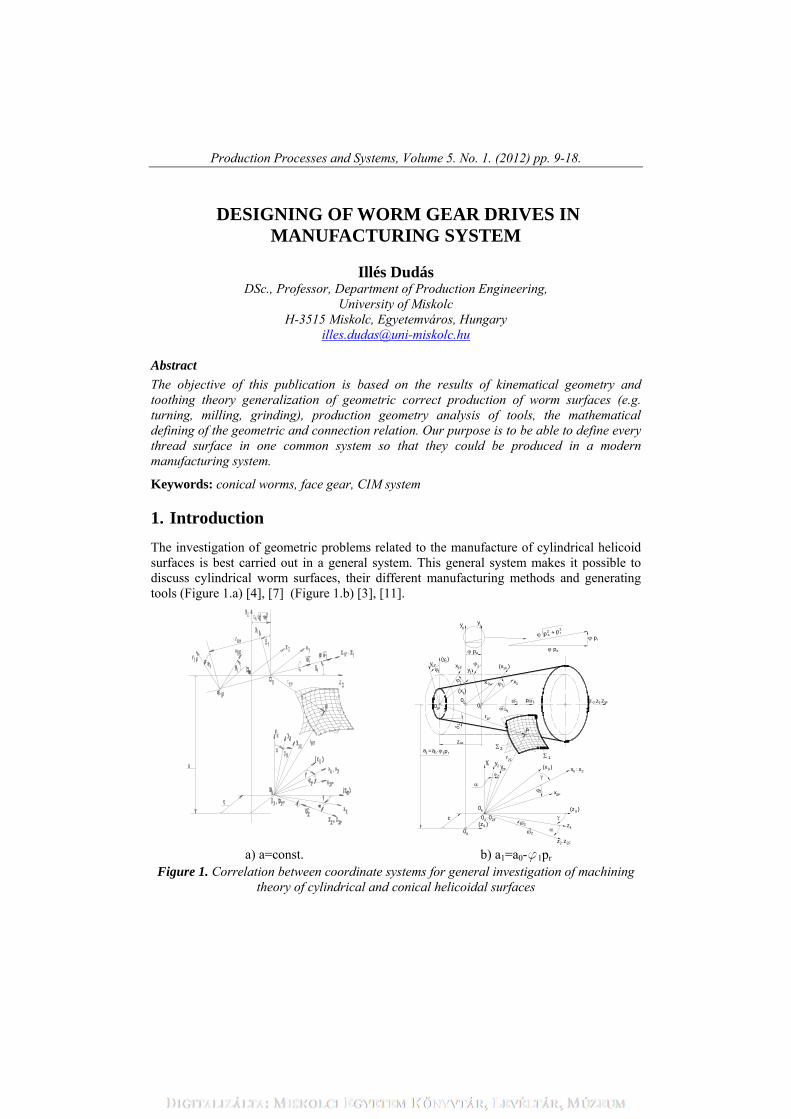
The investigation of geometric problems related to the manufacture of cylindrical helicoid surfaces is best carried out in a general system. This general system makes it possible to discuss cylindrical worm surfaces, their different manufacturing methods and generating tools (Figure 1.a) [4], [7] (Figure 1.b) [3], [11].
a) a=const. b) a1=a0-ϕ1pr
Figure 1. Correlation between coordinate systems for general investigation of machining theory of cylindrical and conical helicoidal surfaces
Illés Dudás
10
2. Realization of the general mathematical model
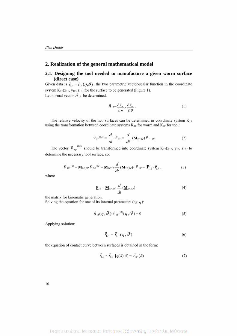
2.1. Designing the tool needed to manufacture a given worm surface (direct case)
Given data is ),(11 FF rr
, the two parametric vector-scalar function in the coordinate
system K1F(x1F, y1F, z1F) for the surface to be generated (Figure 1). Let normal vector n
1F be determined.
n
1F= 1 1F Fr r
η
. (1)
The relative velocity of the two surfaces can be determined in coordinate system K2F
using the transformation between coordinate systems K1F for worm and K2F for tool:
v
2F(12) =
d
dt r
2F = d
dt (M2F,1F) r
1F. (2)
The vector )12(
2v F
should be transformed into coordinate system K1F(x1F, y1F, z1F) to
determine the necessary tool surface, so:
v
1F(12) = M1F,2Fv
2F
(12) = M1F,2Fd
dt(M2F,1F) r
1F = 1 1h Fr
P , (3)
where
P1h = M1F,2F d
dt(M2F,1F) (4)
the matrix for kinematic generation. Solving the equation for one of its internal parameters (eg ):
n
1F(η , )v
1F(12)(η , ) = 0 (5)
Applying solution:
1Fr
= 1Fr
(η , ) (6)
the equation of contact curve between surfaces is obtained in the form:
1Fr
= 1Fr
[η(),] = 1Fr
() (7)
Designing of warm gear drives
11
which is suitable for transformation of:
2Fr
( ) = M2F,1F 1Fr
( ) (8)
into the tool generating system which is the generating curve of the tool. FFM 1,2 and
FFM 2,1 are the transformation matrices between coordinate systems K1F and K2F.
2.2. Determination of worm surface that can be manufactured using a given tool surface (indirect case)
The procedure is similar to the steps carried out in the direct case, but the direction of transformation is the opposite [4]. Known data:
2Fr
= 2Fr
(y20
,), (9)
2Fn
= 2 2
20
F Fr r
y
, (10)
2Fv
= P2h 2Fr
, (11)
where
P2h = M2F,1Fd
dt(M1F,2F)
(12) the matrix for kinematic generation for inverse operation. Solving the following system of equations:
2Fn
2Fv
= 0
(13) and
1Fr
= M1F,2F 2Fr
(14)
Solving these equations, enables the optiman tool profile geometry to be determined. The position vectors
Fr2
or
Fr1
describe the searched surfaces obtained in the direct or
the indirect case; these surfaces can be generated using modern CNC machine tools or traditional machine tools supplied with additional equipment.
Illés Dudás
12
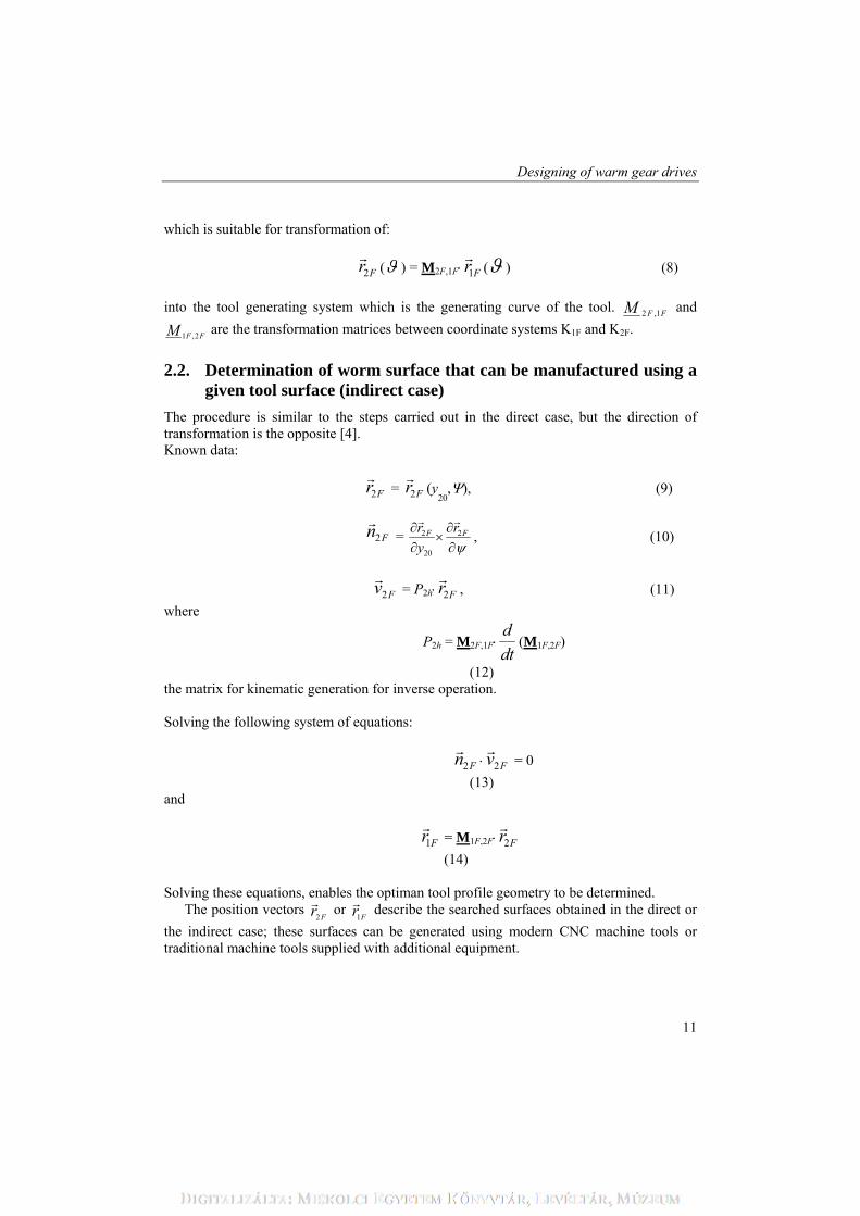
a) Model of cylindrical worm gearing
= 0 a > 0 zax = 0 c = 0 = 0 = –90
b) Model of spiroid worm gearing
> 0 a > 0 zax > 0 c > 0 = –90 = 0
c) Grinding model of cylindrical worm
= 0 a > 0 zax = 0 c = 0 = 0 > 0
Figure 2. Main areas of application of general model
Designing of warm gear drives
13
3. Manufacture of helicoidal surfaces in modern intelligent integrated system
At each stage in the process of production of worm gear drives, during design, manufacture and assembly, faults can occur. Modern intelligent integrated systems (ISS) can handle manufacturing in a versatile and flexible way; they can be efficiently utilized both in design and at the different phases of manufacture to improve product quality. Artificial intelligence and expert systems can now be used in the production of worm gear drives.
The intelligent integrated system (ISS) (for worm gear drives) provides the following: 1. Giving design specifications (module, number of threads, number of
revolutions, etc.); 2. Detailed design (choice of engineering material, determination of basic
geometric data, etc.); 3. Checking of documentation; 4. Preparing CAD drawings; 5. Manufacture; 6. Measurements.
During measurement the tasks are checking with CNC device the surface determined using basic data, analysis of the deviations and feeding them back into manufacturing process (e.g. wheel profile, machine and tool adjustments, etc.).
The design and manufacture high-power transmitting worm gear drives have always raised problems. Subsequent to the development of spur cylindrical gear drives, there has been an increasing demand for different types of drive with:
kinematic drives (both for intersecting and for skew axes); ever-increasing transmission power capability; reduction of noise level between the interacting surfaces.
Some of these requirements demand changes in construction and others, in
manufacturing technology used to lubricate gears. The above-mentioned operational characteristics (geometry, precise manufacture and
assembly) are closely related to each other and engineers, both designers and production planning specialists, require a high level of expertise. Much of this expertise is realized in the actual manufacturing process (e.g. worm grinding) and assembly (e.g. adjusting the proximity of the active contact surface) because most of the required operational characteristics can be attained during manufacture and assembly.
Illés Dudás
14
a)
Designing of warm gear drives
15
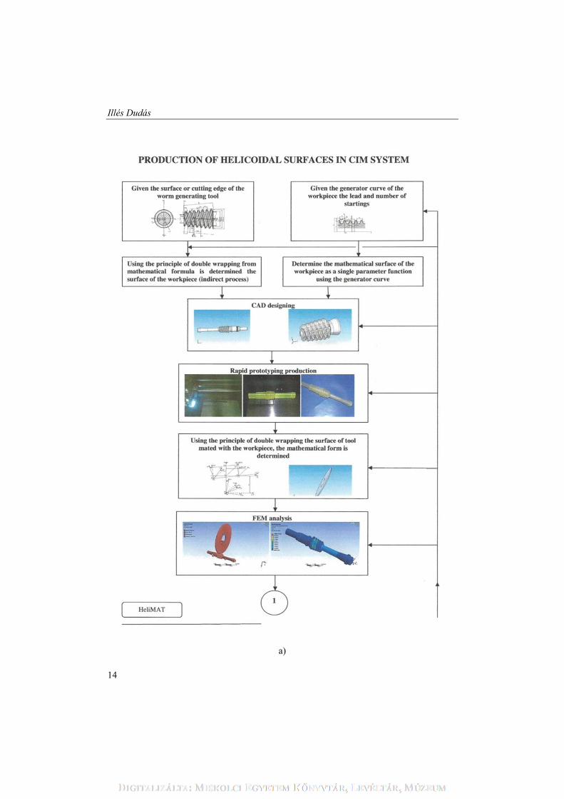
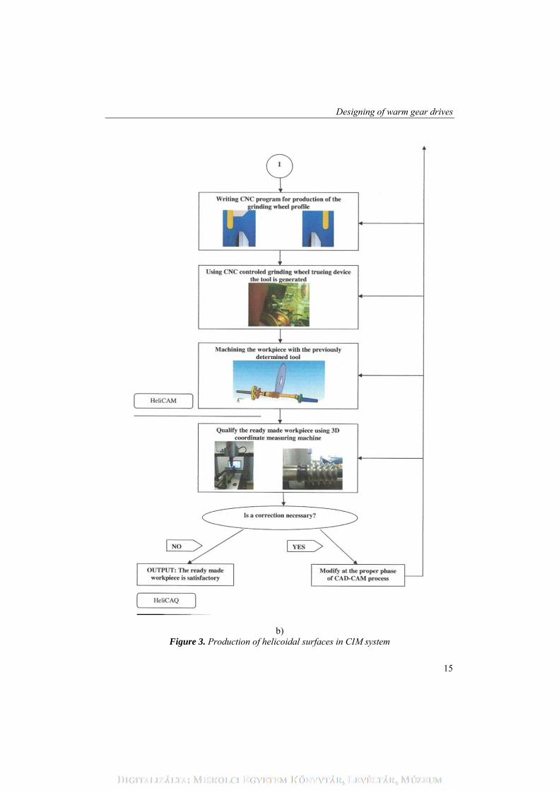
b) Figure 3. Production of helicoidal surfaces in CIM system
Illés Dudás
16
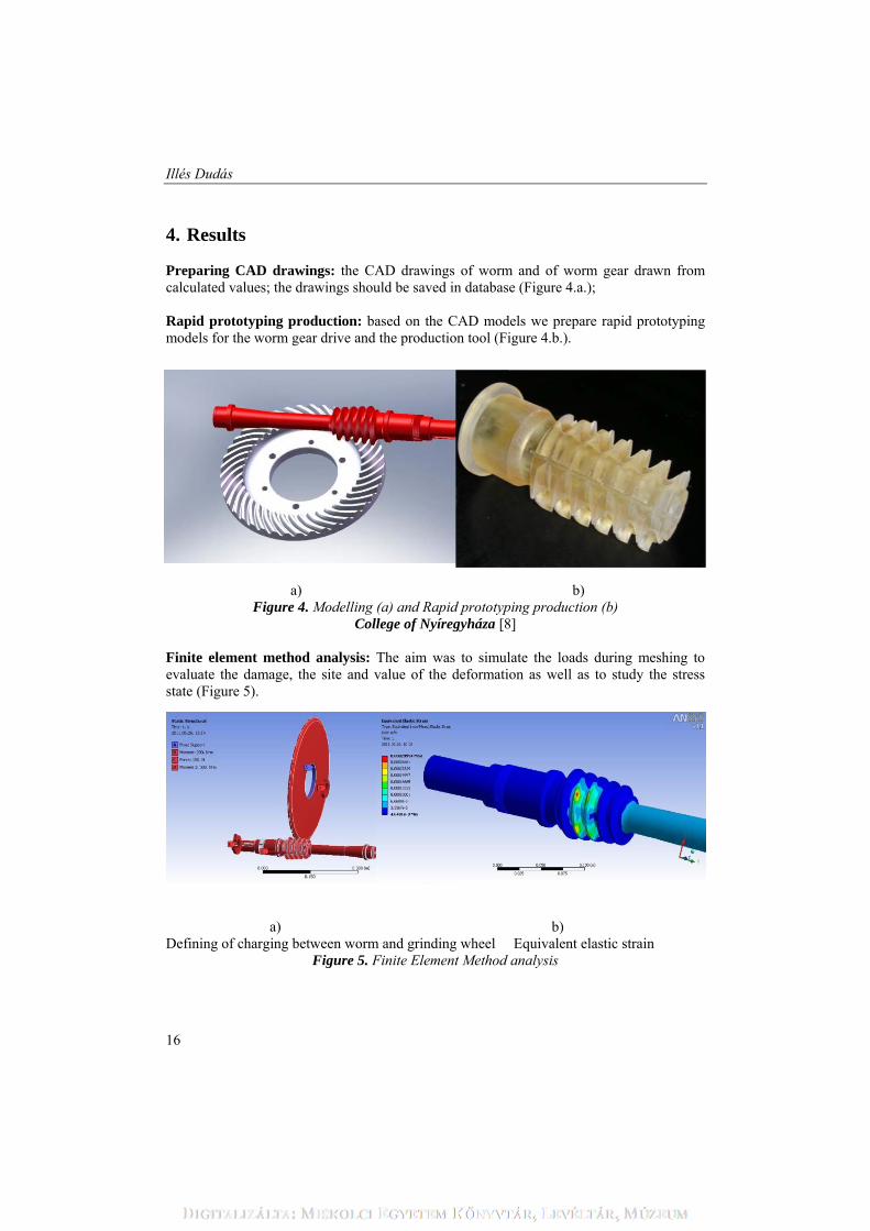
4. Results Preparing CAD drawings: the CAD drawings of worm and of worm gear drawn from calculated values; the drawings should be saved in database (Figure 4.a.); Rapid prototyping production: based on the CAD models we prepare rapid prototyping models for the worm gear drive and the production tool (Figure 4.b.).
a) b) Figure 4. Modelling (a) and Rapid prototyping production (b)
College of Nyíregyháza [8] Finite element method analysis: The aim was to simulate the loads during meshing to evaluate the damage, the site and value of the deformation as well as to study the stress state (Figure 5).
a) b)
Defining of charging between worm and grinding wheel Equivalent elastic strain Figure 5. Finite Element Method analysis
Designing of warm gear drives
17
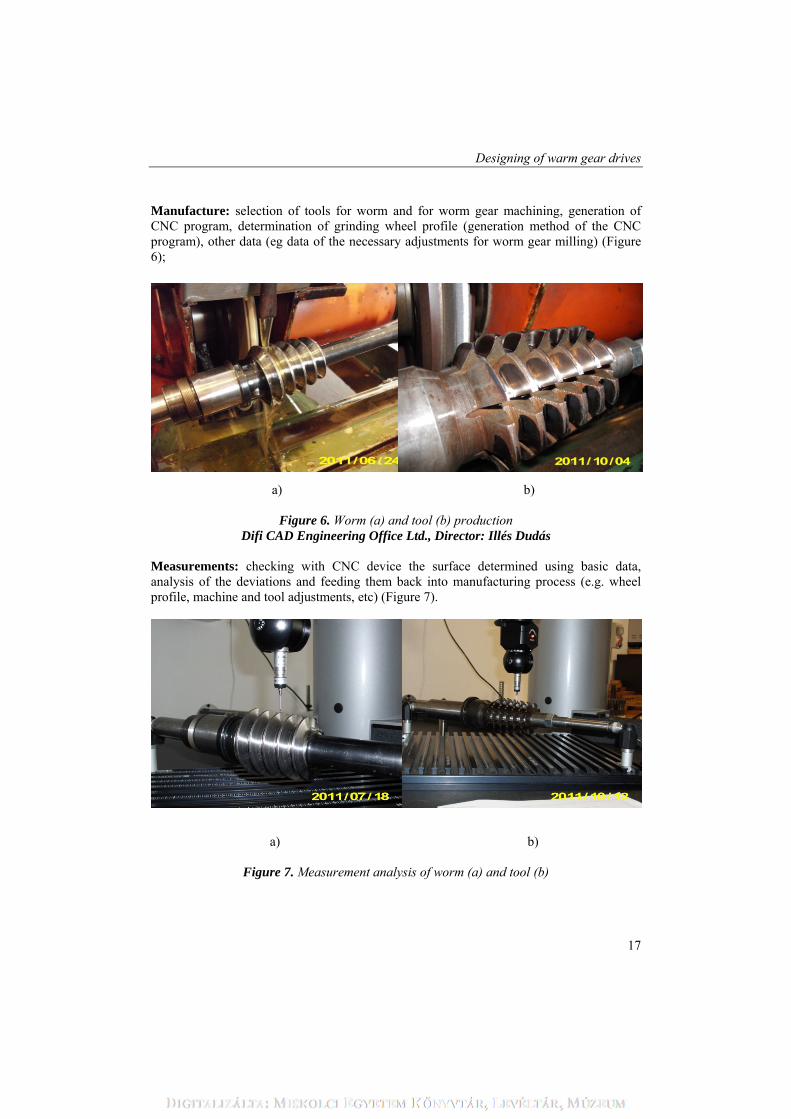
Manufacture: selection of tools for worm and for worm gear machining, generation of CNC program, determination of grinding wheel profile (generation method of the CNC program), other data (eg data of the necessary adjustments for worm gear milling) (Figure 6);
a) b)
Figure 6. Worm (a) and tool (b) production
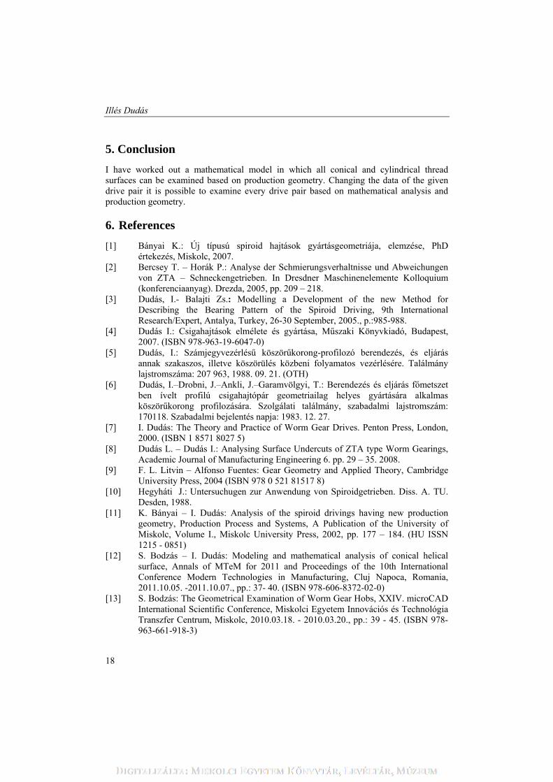
Difi CAD Engineering Office Ltd., Director: Illés Dudás Measurements: checking with CNC device the surface determined using basic data, analysis of the deviations and feeding them back into manufacturing process (e.g. wheel profile, machine and tool adjustments, etc) (Figure 7).
a) b)
Figure 7. Measurement analysis of worm (a) and tool (b)
Illés Dudás
18
5. Conclusion
I have worked out a mathematical model in which all conical and cylindrical thread surfaces can be examined based on production geometry. Changing the data of the given drive pair it is possible to examine every drive pair based on mathematical analysis and production geometry.
6. References
[1] Bányai K.: Új típusú spiroid hajtások gyártásgeometriája, elemzése, PhD értekezés, Miskolc, 2007.
[2] Bercsey T. – Horák P.: Analyse der Schmierungsverhaltnisse und Abweichungen von ZTA – Schneckengetrieben. In Dresdner Maschinenelemente Kolloquium (konferenciaanyag). Drezda, 2005, pp. 209 – 218.
[3] Dudás, I.- Balajti Zs.: Modelling a Development of the new Method for Describing the Bearing Pattern of the Spiroid Driving, 9th International Research/Expert, Antalya, Turkey, 26-30 September, 2005., p.:985-988.
[4] Dudás I.: Csigahajtások elmélete és gyártása, Műszaki Könyvkiadó, Budapest, 2007. (ISBN 978-963-19-6047-0)
[5] Dudás, I.: Számjegyvezérlésű köszörűkorong-profilozó berendezés, és eljárás annak szakaszos, illetve köszörülés közbeni folyamatos vezérlésére. Találmány lajstromszáma: 207 963, 1988. 09. 21. (OTH)
[6] Dudás, I.–Drobni, J.–Ankli, J.–Garamvölgyi, T.: Berendezés és eljárás főmetszet ben ívelt profilú csigahajtópár geometriailag helyes gyártására alkalmas köszörűkorong profilozására. Szolgálati találmány, szabadalmi lajstromszám: 170118. Szabadalmi bejelentés napja: 1983. 12. 27.
[7] I. Dudás: The Theory and Practice of Worm Gear Drives. Penton Press, London, 2000. (ISBN 1 8571 8027 5)
[8] Dudás L. – Dudás I.: Analysing Surface Undercuts of ZTA type Worm Gearings, Academic Journal of Manufacturing Engineering 6. pp. 29 – 35. 2008.
[9] F. L. Litvin – Alfonso Fuentes: Gear Geometry and Applied Theory, Cambridge University Press, 2004 (ISBN 978 0 521 81517 8)
[10] Hegyháti J.: Untersuchugen zur Anwendung von Spiroidgetrieben. Diss. A. TU. Desden, 1988.
[11] K. Bányai – I. Dudás: Analysis of the spiroid drivings having new production geometry, Production Process and Systems, A Publication of the University of Miskolc, Volume I., Miskolc University Press, 2002, pp. 177 – 184. (HU ISSN 1215 - 0851)
[12] S. Bodzás – I. Dudás: Modeling and mathematical analysis of conical helical surface, Annals of MTeM for 2011 and Proceedings of the 10th International Conference Modern Technologies in Manufacturing, Cluj Napoca, Romania, 2011.10.05. -2011.10.07., pp.: 37- 40. (ISBN 978-606-8372-02-0)
[13] S. Bodzás: The Geometrical Examination of Worm Gear Hobs, XXIV. microCAD International Scientific Conference, Miskolci Egyetem Innovációs és Technológia Transzfer Centrum, Miskolc, 2010.03.18. - 2010.03.20., pp.: 39 - 45. (ISBN 978-963-661-918-3)