Embed Size (px)
Citation preview

Steve Green
24th AES UK Conference
June 2011
Designing Microphone Preamplifiers

This presentation is an abbreviated version of a
tutorial given at the
2010 AES Conference in San Francisco.
The complete tutorial is available at
http://www.thatcorp.com/Seminars.shtml
3 Microphone Preamplifier Design
24th UK AES Conference, June 2011
Copyright ©2011, THAT Corporation
Overview
Section 1
Support Circuitry
Section 2
The Amplifier

4 Microphone Preamplifier Design
24th UK AES Conference, June 2011
Copyright ©2011, THAT Corporation
Simple Block Diagram
Microphone signal levels vary widely due to:
• Microphone sensitivity
• Source SPL
• Proximity to source
Line level outputs are somewhat more constrained:
• “Standard” maximum operating levels include 24, 18, 15 dBu
• A/D converter input levels are approximately 8 dBu or 2 Vrms
differential
Microphone input Line level outputAmplifier

5 Microphone Preamplifier Design
24th UK AES Conference, June 2011
Copyright ©2011, THAT Corporation
Typical Requirements
Gain
• Up to 40 dB covers the majority of close-mic’d applications
• Some situations require more than 70 dB
• Variability of input levels requires adjustable gain over a very wide
range
Phantom Power
• Required for many microphones
• Standardized in IEC EN 61938
48 Volts +/- 4V at up to 10 mA per microphone
• On / off control
Input Pad
• Can allow higher input signal levels, at the expense of noise
• May be required depending on minimum gain and supply rails
• 20 dB is common
Resistant to common mode noise and RFI
Reliable

6 Microphone Preamplifier Design
24th UK AES Conference, June 2011
Copyright ©2011, THAT Corporation
Preamplifier Technologies
Transformer-Coupled Vacuum Tube
• Robust
• Colorful
• Costly
Transformer-Coupled Solid State
• Also robust
• Performance can be excellent
• Cost can be high
Transformerless Solid State
• More vulnerable
• Performance can be excellent
• Cost ranges from very low to high
Transformerless solid state designs are the focus today

7 Microphone Preamplifier Design
24th UK AES Conference, June 2011
Copyright ©2011, THAT Corporation
Amplifier Input Bias Current
Must provide a DC current path to supply the amplifier input bias current
IN+
IN-
Rg1
Rg2
R1 R2
+
G
-

8 Microphone Preamplifier Design
24th UK AES Conference, June 2011
Copyright ©2011, THAT Corporation
Gain Control
The amplifier is often designed to vary gain using a single variable
resistor (Rg)
Manually controlled options
• Potentiometer with continuous control over a defined range
• Switched resistor network with a fixed number of steps and gain settings
Digitally controlled options
• Digitally switched resistor network with a predetermined number of steps
• Switches are either relays or silicon devices
• Both discrete and integrated circuit solutions are available
IN+
IN-
Rg
Rg1
Rg2
R1 R2
+
G
-

9 Microphone Preamplifier Design
24th UK AES Conference, June 2011
Copyright ©2011, THAT Corporation
Phantom Power
– C1 and C2 required to block the 48 V from the amplifier inputs
– 6.81k series resistors are specified in the standards for 48V phantom
power
– On/Off is available via a
• Simple mechanical switch in manual applications
• Relay or silicon switch in digitally controlled systems
IN+
IN-
Rg
Rg1
Rg2
6k81 6k81
+
+
C1
C2R1 R2
+48V
+
G
-
Phantom Power

10 Microphone Preamplifier Design
24th UK AES Conference, June 2011
Copyright ©2011, THAT Corporation
Input Pad
• Input pad is simply a signal attenuator prior to the amplifier
• This is a differential-only pad, it does not attenuate common-
mode signals
IN+
IN-
Rg
Rg1
Rg2
6k81
+
+
C1
C2R1 R2
+48V
+
G
-
Phantom Power
6k81
R3
R4
R5
Input Pad

11 Microphone Preamplifier Design
24th UK AES Conference, June 2011
Copyright ©2011, THAT Corporation
“Complete” Microphone Preamp
IN+
IN-
Rg
Rg1
Rg2
6k81 6k81
+
+
C1
C2R1 R2
+48V
R3
R4
R5
+
G
-
Input Pad
Phantom Power

12 Microphone Preamplifier Design
24th UK AES Conference, June 2011
Copyright ©2011, THAT Corporation
It would be nice to say “that’s all there is”
but………
there are gremlins in the details!!

13 Microphone Preamplifier Design
24th UK AES Conference, June 2011
Copyright ©2011, THAT Corporation
DC Offset Changes
• Changes in gain can result in the DC offset changes at the output of the amplifier
• 2 solutions are available
– Adding a capacitor (Cg) sets the DC gain to a fixed value and avoids these offset
changes
– A servo-amplifier can also be effective, but we don’t have time to discuss them today
IN+
IN-
Rg1
Rg2
6k81 6k81
+
+
C1
C2R1 R2
+48V
R3
R4
R5
+
G
-
Input Pad
Phantom Power
Rg Cg
14 Microphone Preamplifier Design
24th UK AES Conference, June 2011
Copyright ©2011, THAT Corporation
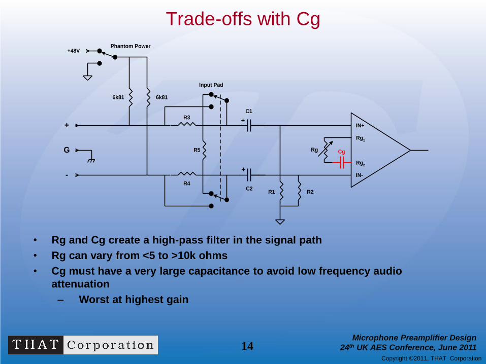
Trade-offs with Cg
IN+
IN-
Rg1
Rg2
6k81 6k81
+
+
C1
C2R1 R2
+48V
R3
R4
R5
+
G
-
Input Pad
Phantom Power
Rg Cg
• Rg and Cg create a high-pass filter in the signal path
• Rg can vary from <5 to >10k ohms
• Cg must have a very large capacitance to avoid low frequency audio
attenuation
– Worst at highest gain
15 Microphone Preamplifier Design
24th UK AES Conference, June 2011
Copyright ©2011, THAT Corporation
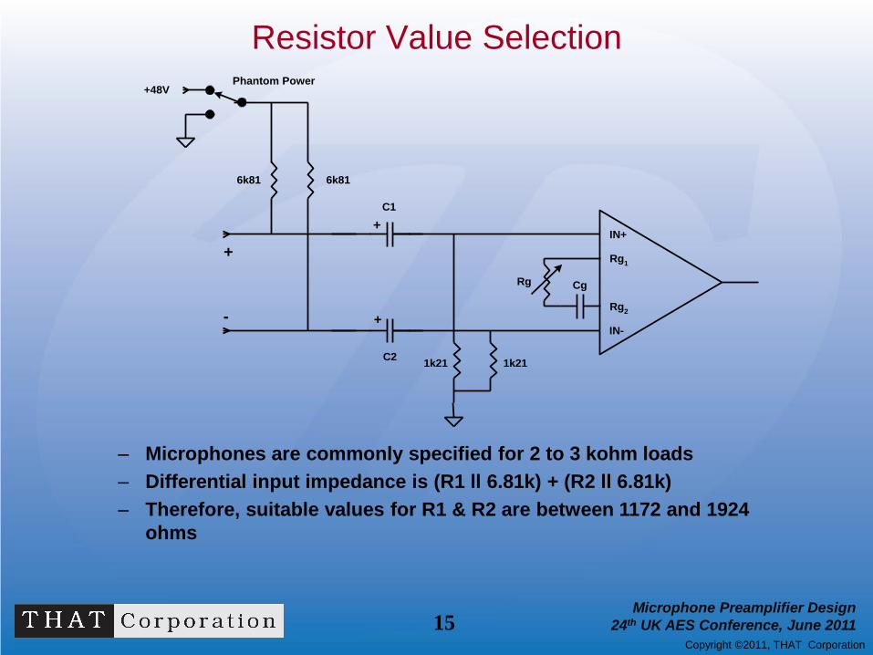
Resistor Value Selection
– Microphones are commonly specified for 2 to 3 kohm loads
– Differential input impedance is (R1 ll 6.81k) + (R2 ll 6.81k)
– Therefore, suitable values for R1 & R2 are between 1172 and 1924
ohms
IN+
IN-
Rg1
Rg2
6k81 6k81
+
+
C1
C21k21 1k21
+48V
+
-
Phantom Power
Rg Cg
16 Microphone Preamplifier Design
24th UK AES Conference, June 2011
Copyright ©2011, THAT Corporation
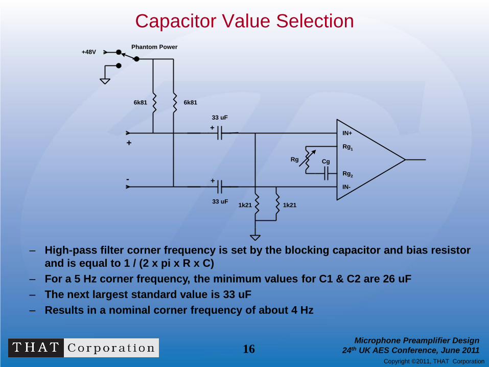
Capacitor Value Selection
– High-pass filter corner frequency is set by the blocking capacitor and bias resistor
and is equal to 1 / (2 x pi x R x C)
– For a 5 Hz corner frequency, the minimum values for C1 & C2 are 26 uF
– The next largest standard value is 33 uF
– Results in a nominal corner frequency of about 4 Hz
IN+
IN-
Rg1
Rg2
6k81 6k81
+
+
33 uF
33 uF1k21 1k21
+48V
+
-
Phantom Power
Rg Cg

17 Microphone Preamplifier Design
24th UK AES Conference, June 2011
Copyright ©2011, THAT Corporation
Alternative Resistor-Capacitor Value Selection
IN+
IN-
Rg1
Rg2
6k81 6k81
+
+
C1
C210k 10k
+48V
+
-
Phantom Power
Rg CgRt
– C1 and C2 can be made smaller if bias resistors are made larger
– Rin is defined by Rt
– However, C1 and C2 convert 1/f noise to 1/f^2 noise
– 10k resistors contribute thermal noise and current noise*R
18 Microphone Preamplifier Design
24th UK AES Conference, June 2011
Copyright ©2011, THAT Corporation
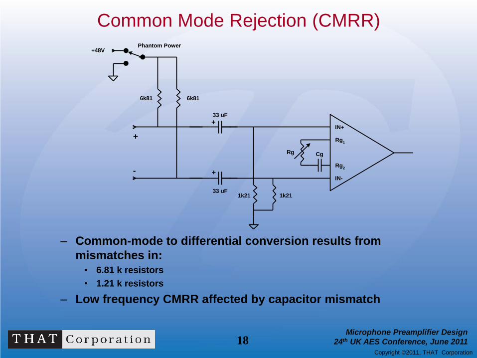
Common Mode Rejection (CMRR)
– Common-mode to differential conversion results from
mismatches in: • 6.81 k resistors
• 1.21 k resistors
– Low frequency CMRR affected by capacitor mismatch
IN+
IN-
Rg1
Rg2
6k81 6k81
+
+
33 uF
33 uF1k21 1k21
+48V
+
-
Phantom Power
Rg Cg

19 Microphone Preamplifier Design
24th UK AES Conference, June 2011
Copyright ©2011, THAT Corporation
U-Pad Attenuator
• ZIN with and without pad can be closely matched
• Can be designed for any attenuation – 20dB is typical
• Noise performance is degraded
• Better noise, less headroom with less attenuation
IN+
IN-
Rg1
Rg2
6k81 6k81
1k21 1k21
+48V
R3
R4
R5
+
G
-
Input Pad
Phantom Power
Rg Cg

20 Microphone Preamplifier Design
24th UK AES Conference, June 2011
Copyright ©2011, THAT Corporation
Example -20 dB Input Pad
• ZIN with and without pad is approximately 2k
• 20 dB Attenuation
• Pad output impedance is approximately 240 ohms
• See THAT Design Note DN-140 for details and alternatives
IN+
IN-
Rg1
Rg2
6k81 6k81
+
+
33 uF
33 uF1k21 1k21
+48V
1k1
1k1
267
+
G
-
20 dB Pad
Phantom Power
Rg Cg

21 Microphone Preamplifier Design
24th UK AES Conference, June 2011
Copyright ©2011, THAT Corporation
RFI Protection
RFI protection is required in any practical design
100 pf caps at the input connector attenuate differential and common-mode RFI
470 pf cap at amplifier input pins reduces differential high frequencies from both
internal and external sources
470 pf
100 pf
100 pf
IN+
IN-
Rg1
Rg2
6k81 6k81
+
+
33 uF
33 uF1k21 1k21
+48V
1k1
1k1
267
+
G
-
Input Pad
Phantom Power
Rg Cg
C1
C2

22 Microphone Preamplifier Design
24th UK AES Conference, June 2011
Copyright ©2011, THAT Corporation
Phantom Power Faults
• Shorting input pins to ground with phantom turned on – 33uF coupling caps C1 & C2 start charged to 48V
– Positive end of C1, C2 connect to ground
– Negative end of C1, C2 driven to -48V!
• The shorting sequence can vary – “Single-ended”: One input to ground
– “Common-mode”: both inputs to ground simultaneously
– “Differential”: One input to ground, then the other
– Differential is worst
• Big currents flow as C1, C2 discharge – Currents over 3 amperes flow in the capacitors

23 Microphone Preamplifier Design
24th UK AES Conference, June 2011
Copyright ©2011, THAT Corporation
Phantom Fault Protection
• Limit the current with small value resistors
• Direct fault currents away from the amplifier inputs
– Input diodes provide a conduction path which bypasses the amplifier
– This current varies with gain setting
• Diode bridge directs fault current to rails
– Consider impact on supply rails
– Minimize supply transient with capacitance
IN+
IN-
Rg
Rg1
Rg2
Cg
1k21 1k21
10R
10R
Protection
Bridge
+
+
VCC
VEE
~ ~
+ -
470 pf
100 pf
100 pf
6k81 6k81
+
+
33 uF
33 uF
+48V
1k1
1k1
267
+
G
-
20 dB Pad
Phantom Power
C1
C2

24 Microphone Preamplifier Design
24th UK AES Conference, June 2011
Copyright ©2011, THAT Corporation
Complete Microphone Preamp
IN+
IN-
Rg
Rg1
Rg2
Cg
6k8 6k8
+
+
33 uF
33 uF1k21 1k21
10R
10R
+48V
470 pf
1k1
1k1
267
100pf
100pf
+
G
-
Protection
Bridge
+
+
VCC
VEE
~ ~
+ -20 dB Pad
Phantom Power

25 Microphone Preamplifier Design
24th UK AES Conference, June 2011
Copyright ©2011, THAT Corporation
References and Additional Information
– THAT Corp “THAT 1510/1512” data sheet
– THAT Corp “THAT 1570 & 5171” data sheets,
– THAT Corp “Design Note 140”
– THAT Corp “Design Note 138”
– THAT Corp “Analog Secrets Your Mother Never Told You”
– THAT Corp “More Analog Secrets Your Mother Never Told You”
– “The 48 Volt Phantom Menace Returns” Audio Engineering Society Preprint from the
127th AES Convention, Oct 2009
– “The 48 Volt Phantom Menace” Audio Engineering Society Preprint from the 110th
AES Convention, May 2001
All THAT Corp references are available at thatcorp.com

26 Microphone Preamplifier Design
24th UK AES Conference, June 2011
Copyright ©2011, THAT Corporation
Amplifier Topologies
What’s inside the triangle?

27 Microphone Preamplifier Design
24th UK AES Conference, June 2011
Copyright ©2011, THAT Corporation
Scope
• We will concentrate on topologies that allow a
wide range of gain with a single control.
• The goal is to balance the requirements for
low distortion and low noise at both ends of
the gain range.

28 Microphone Preamplifier Design
24th UK AES Conference, June 2011
Copyright ©2011, THAT Corporation
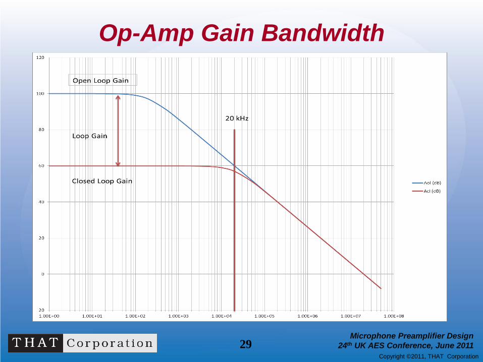
What About Op-amps?
• Voltage feedback op-amps have fixed Gain Bandwidth (GBW)
product
• A 20 MHz GBW op-amp may have no loop gain at 20 kHz when
set for 60 dB closed loop gain
• Direct correlation between distortion and loop gain
• Most are too noisy (and we need 2 for a differential input)
• We can add a pair of transistors to help
29 Microphone Preamplifier Design
24th UK AES Conference, June 2011
Copyright ©2011, THAT Corporation
Op-Amp Gain Bandwidth

30 Microphone Preamplifier Design
24th UK AES Conference, June 2011
Copyright ©2011, THAT Corporation
Simple Mic Preamp
• Q1 and Q2 are simple
current-feedback
amplifiers
• Diff Gain = 22k/(re +
Rg/2||14.3k)
• where re = 1/gm = KT/qIC
= 26 ohms
• “re” varies with signal,
resulting in THD
• Minimum gain =
22k/14.3k = 3.7 dB

31 Microphone Preamplifier Design
24th UK AES Conference, June 2011
Copyright ©2011, THAT Corporation
Complementary Feedback Pair
• Input devices are each
a compound transistor
(Complementary
Feedback Pair)
• Output impedance at
NPN emitters is reduced
• Still signal-dependent,
but much less
• Gain = 5k/(re/74 +
Rg/2||2.87k)
• Minimum Gain =
5k/2.87k = 4.8 dB

32 Microphone Preamplifier Design
24th UK AES Conference, June 2011
Copyright ©2011, THAT Corporation
Current Feedback Instrumentation Amp
• Topology used in most integrated microphone
preamplifiers
• Scott Wurcer – AD524 IEEE Paper 12/82
• Graeme Cohen AES Paper – “Double Balanced
Microphone Amplifier” 9/84

33 Microphone Preamplifier Design
24th UK AES Conference, June 2011
Copyright ©2011, THAT Corporation
What’s “Current Feedback”?
• Closed loop bandwidth
stays substantially constant
with closed loop gain until re
becomes a significant factor
• Open loop gain and closed
loop gain vary together
• Rf controls BW

34 Microphone Preamplifier Design
24th UK AES Conference, June 2011
Copyright ©2011, THAT Corporation
Basic CFIA Mic Preamp
• Large loop gain (A)
keeps Q1 & Q2 current
constant
• Current sources I1 and
I2 allow for unity gain
• Gain = 1 + (2R7/Rg)
• Min. gain = 0 dB

35 Microphone Preamplifier Design
24th UK AES Conference, June 2011
Copyright ©2011, THAT Corporation
Refinements to the CFIA
• Eliminating major sources of THD exposes more subtle distortion mechanisms
• Additional circuitry, such as cascoded current sources and folded cascode loads, can minimize these effects
• At this level of complexity an IC makes sense
• Good device matching inherent in integrated circuits improves performance

36 Microphone Preamplifier Design
24th UK AES Conference, June 2011
Copyright ©2011, THAT Corporation
A Real Example CFIA
• An integrated circuit current-feedback instrumentation amplifier front end
• Utilizes the techniques described on the previous slide
• Compensated for RF values down to 2 kohm

37 Microphone Preamplifier Design
24th UK AES Conference, June 2011
Copyright ©2011, THAT Corporation
Example CFIA Bandwidth vs. Gain
1570 Bandwidth vs. Gain
1.00E+05
1.00E+06
1.00E+07
1.00E+08
0 10 20 30 40 50 60 70
Gain (dB)
-3d
B B
W (
Hz)
Rf = 2.21k
Rf = 4.02k

38 Microphone Preamplifier Design
24th UK AES Conference, June 2011
Copyright ©2011, THAT Corporation
THD Performance Comparison
THD vs. Gain, +20 dBu Out, Rf = 2.21k
THD vs. Gain, +20 du Out
0.00001
0.0001
0.001
0.01
0.1
1
0 10 20 30 40 50 60 70
Gain (dB)
TH
D (
%) Simple MP
CFP MP
1570 1 kHz
1570 10 kHz

39 Microphone Preamplifier Design
24th UK AES Conference, June 2011
Copyright ©2011, THAT Corporation
Noise Performance Comparison
EIN (dBu, 20 Hz - 20 kHz, Rs = 150, Rf = 2.21k) vs. Gain (dB)
-130.0
-120.0
-110.0
-100.0
-90.0
0 10 20 30 40 50 60 70
Gain (dB)
EIN
(d
Bu
)
Simple Mic Pre
CFP MP
1570

40 Microphone Preamplifier Design
24th UK AES Conference, June 2011
Copyright ©2011, THAT Corporation
Conclusions
• Microphone preamplifiers with a wide gain range controlled by a
single resistance involve trade-offs between low-gain noise and
high-gain distortion performance
• The current-feedback instrumentation amplifier is capable of
good performance at both extremes
• An integrated approach can provide excellent performance in
very small PCB area at moderate cost

41 Microphone Preamplifier Design
24th UK AES Conference, June 2011
Copyright ©2011, THAT Corporation
Acknowledgements
Many thanks to Gary Hebert for his assistance (and
patience) in preparation for this tutorial.

Questions ?