Embed Size (px)
Citation preview
DESIGNING GRAPHICS ARCHITECTURES
AROUND
SCALABILITY AND COMMUNICATION
A DISSERTATION
SUBMITTED TO THE DEPARTMENT OF ELECTRICAL ENGINEERING
AND THE COMMITTEE ON GRADUATE STUDIES
OF STANFORD UNIVERSITY
IN PARTIAL FULFILLMENT OF THE REQUIREMENTS
FOR THE DEGREE OF
DOCTOR OF PHILOSOPHY
Matthew Eldridge
June 2001

c© Copyright by Matthew Eldridge 2001
All Rights Reserved
ii
I certify that I have read this dissertation and that in my opin-
ion it is fully adequate, in scope and quality, as a dissertation
for the degree of Doctor of Philosophy.
Pat Hanrahan(Principal Adviser)
I certify that I have read this dissertation and that in my opin-
ion it is fully adequate, in scope and quality, as a dissertation
for the degree of Doctor of Philosophy.
William J. Dally
I certify that I have read this dissertation and that in my opin-
ion it is fully adequate, in scope and quality, as a dissertation
for the degree of Doctor of Philosophy.
Mark Horowitz
Approved for the University Committee on Graduate Stud-
ies:
iii
Abstract
Communication forms the backbone of parallel graphics, allowing multiple functional units
to cooperate to render images. The cost of this communication, both in system resources
and money, is the primary limit to parallelism. We examine the use of object and image
parallelism and describe architectures in terms of the sorting communication that connects
these forms of parallelism. We introduce an extended taxonomy of parallel graphics archi-
tecture that more fully distinguishes architectures based on their sorting communication,
paying particular attention to the difference between sorting fragments after rasterization,
and sorting samples after fragments are merged with the framebuffer. We introduce three
new forms of communication, distribution, routing and texturing, in addition to sorting.
Distribution connects object parallel pipeline stages, routing connects image parallel pipe-
line stages, and texturing connects untextured fragments with texture memory. All of these
types of communication allow the parallelism of successive pipeline stages to be decoupled,
and thus load-balanced. We generalize communication to include not only interconnect,
which provides communication across space, but also memory, which functions as com-
munication across time. We examine a number of architectures from this communication-
centric perspective, and discuss the limits to their scalability. We draw conclusions to the
limits of both image parallelism and broadcast communication and suggest architectures
that avoid these limitations.
We describe a new parallel graphics architecture called “Pomegranate”, which is de-
signed around efficient and scalable communication. Pomegranate provides scalable input
bandwidth, triangle rate, pixel rate, texture memory and display bandwidth. The basic
unit of scalability is a single graphics pipeline, and up to 64 such units may be combined.
iv
Pomegranate’s scalability is achieved with a novel “sort-everywhere” architecture that dis-
tributes work in a balanced fashion at every stage of the pipeline, keeping the amount of
work performed by each pipeline uniform as the system scales. The use of one-to-one
communication, instead of broadcast, as well as a carefully balanced distribution of work
allows a scalable network based on high-speed point-to-point links to be used for com-
municating between the pipelines. Pomegranate provides one interface per pipeline for
issuing ordered, immediate-mode rendering commands and supports a parallel API that al-
lows multiprocessor applications to exactly order drawing commands from each interface.
A detailed hardware simulation demonstrates performance on next-generation workloads.
Pomegranate operates at 87–99% parallel efficiency with 64 pipelines, for a simulated per-
formance of up to 1.10 billion triangles per second and 21.9 billion pixels per second.
v
Acknowledgements
I would like to thank my advisor, Pat Hanrahan, for his continual guidance. His advice has
been invaluable, as has his patience with my forays into activities far removed from being a
graduate student. I thank the other members of my reading committee, Bill Dally and Mark
Horowitz, for their time and attention to detail. Bill Dally has provided a great engineering
perspective that I have had the pleasure of being exposed to in multiple classes as well as
personally. Mark Horowitz was a source of many insightful suggestions throughout my
career at Stanford. I owe a large debt of gratitude to Kurt Akeley. I have had numerous
enlightening discussions with him, and he has given me a deeper understanding of graphics
architecture. Kurt’s thoughtful comments on my thesis clarified not only my writing but
also my ideas.
Stanford has been a wonderful place to go to school, in large part because of the people I
had the good fortune to work with. In particular, Homan Igehy, Gordon Stoll, John Owens,
Greg Humphreys and Ian Buck have all taught me a great deal. The certainty with which
I argued with them all was nearly always because I was wrong. They, together with Jeff
Solomon, Craig Kolb, Kekoa Proudfoot, Matt Pharr and many others have made being a
graduate student very enjoyable.
The coincidences of my brother Adam attending graduate school at Stanford, David Ro-
driguez self-employing himself in Sunnyvale, and Michael and Tien-Ling Slater relocating
to Berkeley have all made my time outside of school much more pleasurable.
I thank my parents for encouraging me to go to graduate school when I needed to be
pushed, for their enthusiasm when I thought I would leave to go get rich, and for their
constant encouragement to write my thesis when I was dragging my heels.
Finally, I thank the Fannie and John Hertz Foundation for its support, as well as DARPA
contract DABT63-95-C-0085-P00006.
vi
Contents
Abstract iv
Acknowledgements vi
1 Introduction 1
1.1 Graphics Pipeline . . . . . . . . . . . . . . . . . . . . . . . . . . . . . . . 2
1.2 Performance Metrics . . . . . . . . . . . . . . . . . . . . . . . . . . . . . 6
1.3 Communication . . . . . . . . . . . . . . . . . . . . . . . . . . . . . . . . 7
1.4 Scalability . . . . . . . . . . . . . . . . . . . . . . . . . . . . . . . . . . . 8
1.5 Summary of Original Contributions . . . . . . . . . . . . . . . . . . . . . 10
2 Graphics Pipeline 13
2.1 Choices . . . . . . . . . . . . . . . . . . . . . . . . . . . . . . . . . . . . 14
2.2 Terminology . . . . . . . . . . . . . . . . . . . . . . . . . . . . . . . . . . 17
2.3 Communication Costs . . . . . . . . . . . . . . . . . . . . . . . . . . . . 18
2.4 Parallel Interface . . . . . . . . . . . . . . . . . . . . . . . . . . . . . . . 21
3 Parallelism and Communication 24
3.1 Parallelism . . . . . . . . . . . . . . . . . . . . . . . . . . . . . . . . . . 24
3.1.1 Object Parallelism . . . . . . . . . . . . . . . . . . . . . . . . . . 27
3.1.2 Image Parallelism . . . . . . . . . . . . . . . . . . . . . . . . . . . 27
3.1.3 Object Parallel to Image Parallel Transition . . . . . . . . . . . . . 32
3.2 Communication . . . . . . . . . . . . . . . . . . . . . . . . . . . . . . . . 32
3.2.1 Patterns . . . . . . . . . . . . . . . . . . . . . . . . . . . . . . . . 34
3.2.2 Networks . . . . . . . . . . . . . . . . . . . . . . . . . . . . . . . 35
vii
3.2.3 Memory . . . . . . . . . . . . . . . . . . . . . . . . . . . . . . . 38
4 Taxonomy and Architectures 43
4.1 Sort-First . . . . . . . . . . . . . . . . . . . . . . . . . . . . . . . . . . . 46
4.1.1 Sort-First Retained-Mode . . . . . . . . . . . . . . . . . . . . . . 47
4.1.2 Sort-First Immediate-Mode . . . . . . . . . . . . . . . . . . . . . 48
4.2 Sort-Middle . . . . . . . . . . . . . . . . . . . . . . . . . . . . . . . . . . 50
4.2.1 Sort-Middle Interleaved . . . . . . . . . . . . . . . . . . . . . . . 50
4.2.2 Sort-Middle Tiled . . . . . . . . . . . . . . . . . . . . . . . . . . . 50
4.3 Sort-Last Fragment . . . . . . . . . . . . . . . . . . . . . . . . . . . . . . 55
4.4 Sort-Last Image Composition . . . . . . . . . . . . . . . . . . . . . . . . . 56
4.4.1 Pipelined Image Composition . . . . . . . . . . . . . . . . . . . . 57
4.4.2 Non-Pipelined Image Composition . . . . . . . . . . . . . . . . . 60
4.5 Hybrid Architectures . . . . . . . . . . . . . . . . . . . . . . . . . . . . . 62
4.5.1 WireGL + Lightning-2 . . . . . . . . . . . . . . . . . . . . . . . . 63
4.5.2 VC-1 . . . . . . . . . . . . . . . . . . . . . . . . . . . . . . . . . 63
4.6 Observations . . . . . . . . . . . . . . . . . . . . . . . . . . . . . . . . . 65
4.6.1 Interface Limit . . . . . . . . . . . . . . . . . . . . . . . . . . . . 65
4.6.2 Application Visibility of Work . . . . . . . . . . . . . . . . . . . . 70
4.6.3 Texturing . . . . . . . . . . . . . . . . . . . . . . . . . . . . . . . 71
4.6.4 Limits of Image Parallelism . . . . . . . . . . . . . . . . . . . . . 71
5 Pomegranate: Architecture 74
5.1 Overview . . . . . . . . . . . . . . . . . . . . . . . . . . . . . . . . . . . 76
5.2 Scalability and Interface . . . . . . . . . . . . . . . . . . . . . . . . . . . 77
5.3 Architecture . . . . . . . . . . . . . . . . . . . . . . . . . . . . . . . . . . 79
5.3.1 Network . . . . . . . . . . . . . . . . . . . . . . . . . . . . . . . 81
5.3.2 Command Processor . . . . . . . . . . . . . . . . . . . . . . . . . 82
5.3.3 Geometry Processor . . . . . . . . . . . . . . . . . . . . . . . . . 83
5.3.4 Rasterizer . . . . . . . . . . . . . . . . . . . . . . . . . . . . . . . 85
5.3.5 Texture Processor . . . . . . . . . . . . . . . . . . . . . . . . . . . 85
5.3.6 Fragment Processor . . . . . . . . . . . . . . . . . . . . . . . . . . 88
5.3.7 Display . . . . . . . . . . . . . . . . . . . . . . . . . . . . . . . . 89
viii
6 Pomegranate: Ordering and State 91
6.1 Ordering . . . . . . . . . . . . . . . . . . . . . . . . . . . . . . . . . . . . 91
6.1.1 Serial Ordering . . . . . . . . . . . . . . . . . . . . . . . . . . . . 92
6.1.2 Parallel Ordering . . . . . . . . . . . . . . . . . . . . . . . . . . . 97
6.2 State Management . . . . . . . . . . . . . . . . . . . . . . . . . . . . . . 103
6.2.1 State Commands . . . . . . . . . . . . . . . . . . . . . . . . . . . 103
6.2.2 Context Switching . . . . . . . . . . . . . . . . . . . . . . . . . . 106
7 Simulation and Results 108
7.1 Scalability . . . . . . . . . . . . . . . . . . . . . . . . . . . . . . . . . . . 110
7.2 Load Balance . . . . . . . . . . . . . . . . . . . . . . . . . . . . . . . . . 112
7.3 Network Utilization . . . . . . . . . . . . . . . . . . . . . . . . . . . . . 113
7.4 Comparison . . . . . . . . . . . . . . . . . . . . . . . . . . . . . . . . . . 114
8 Discussion 120
8.1 OpenGL and the Parallel API . . . . . . . . . . . . . . . . . . . . . . . . . 120
8.2 Communication . . . . . . . . . . . . . . . . . . . . . . . . . . . . . . . . 121
8.3 Consistency Model . . . . . . . . . . . . . . . . . . . . . . . . . . . . . . 121
8.4 Shared State Management . . . . . . . . . . . . . . . . . . . . . . . . . . 123
8.4.1 Texture Objects . . . . . . . . . . . . . . . . . . . . . . . . . . . . 123
8.4.2 Display Lists . . . . . . . . . . . . . . . . . . . . . . . . . . . . . 125
8.4.3 Virtual Memory . . . . . . . . . . . . . . . . . . . . . . . . . . . . 126
8.5 Automatic Parallelization . . . . . . . . . . . . . . . . . . . . . . . . . . 127
8.6 Pomegranate-2 . . . . . . . . . . . . . . . . . . . . . . . . . . . . . . . . 130
9 Conclusions 132
Bibliography 135
ix
List of Tables
2.1 Communication cost between pipeline stages . . . . . . . . . . . . . . . . 20
3.1 Analysis Notation . . . . . . . . . . . . . . . . . . . . . . . . . . . . . . . 26
3.2 Interconnection Networks . . . . . . . . . . . . . . . . . . . . . . . . . . . 37
4.1 Revised graphics taxonomy and alternative taxonomies . . . . . . . . . . . 45
4.2 Summary of Graphics Architectures . . . . . . . . . . . . . . . . . . . . . 66
6.1 Total FIFO sizes for each functional unit . . . . . . . . . . . . . . . . . . . 96
6.2 Context Size . . . . . . . . . . . . . . . . . . . . . . . . . . . . . . . . . . 105
7.1 Benchmark Scenes . . . . . . . . . . . . . . . . . . . . . . . . . . . . . . 109
7.2 Load balance for Nurbs . . . . . . . . . . . . . . . . . . . . . . . . . . . . 112
7.3 Load balance for March . . . . . . . . . . . . . . . . . . . . . . . . . . . . 113
7.4 Load balance for Tex3D . . . . . . . . . . . . . . . . . . . . . . . . . . . . 113
7.5 Network traffic by type on a 64-pipeline Pomegranate . . . . . . . . . . . . 114
x
List of Figures
1.1 Polygon Rendering Pipeline . . . . . . . . . . . . . . . . . . . . . . . . . 2
1.2 Parallel Graphics Performance Metrics . . . . . . . . . . . . . . . . . . . . 6
2.1 Graphics Pipeline Model . . . . . . . . . . . . . . . . . . . . . . . . . . . 14
2.2 Graphics Architecture Terminology . . . . . . . . . . . . . . . . . . . . . 17
2.3 Pipeline Communication Bandwidths . . . . . . . . . . . . . . . . . . . . 19
2.4 Parallel API Example . . . . . . . . . . . . . . . . . . . . . . . . . . . . . 22
3.1 Image Parallelism Choices . . . . . . . . . . . . . . . . . . . . . . . . . . 28
3.2 Communication Patterns . . . . . . . . . . . . . . . . . . . . . . . . . . . 34
3.3 Interconnects . . . . . . . . . . . . . . . . . . . . . . . . . . . . . . . . . 36
3.4 Texture Prefetching . . . . . . . . . . . . . . . . . . . . . . . . . . . . . . 39
4.1 Sorting Locations . . . . . . . . . . . . . . . . . . . . . . . . . . . . . . . 44
4.2 Princeton Scalable Display Wall . . . . . . . . . . . . . . . . . . . . . . . 47
4.3 WireGL . . . . . . . . . . . . . . . . . . . . . . . . . . . . . . . . . . . . 49
4.4 SGI InfiniteReality . . . . . . . . . . . . . . . . . . . . . . . . . . . . . . 51
4.5 Argus . . . . . . . . . . . . . . . . . . . . . . . . . . . . . . . . . . . . . 52
4.6 UNC Pixel-Planes 5 . . . . . . . . . . . . . . . . . . . . . . . . . . . . . . 54
4.7 Sort-Last Fragment . . . . . . . . . . . . . . . . . . . . . . . . . . . . . . 55
4.8 UNC PixelFlow . . . . . . . . . . . . . . . . . . . . . . . . . . . . . . . . 58
4.9 Lightning-2 . . . . . . . . . . . . . . . . . . . . . . . . . . . . . . . . . . 59
4.10 Binary-Swap Compositing . . . . . . . . . . . . . . . . . . . . . . . . . . 60
4.11 WireGL and Lightning-2 . . . . . . . . . . . . . . . . . . . . . . . . . . . 62
4.12 Aizu VC-1 . . . . . . . . . . . . . . . . . . . . . . . . . . . . . . . . . . . 64
xi
5.1 Pomegranate Architecture . . . . . . . . . . . . . . . . . . . . . . . . . . 76
5.2 Pomegranate pipeline . . . . . . . . . . . . . . . . . . . . . . . . . . . . . 80
5.3 Butterfly Network . . . . . . . . . . . . . . . . . . . . . . . . . . . . . . . 81
5.4 Texture Stage . . . . . . . . . . . . . . . . . . . . . . . . . . . . . . . . . 86
5.5 Texture Memory Organization . . . . . . . . . . . . . . . . . . . . . . . . 87
5.6 Pixel Quad Memory Layout . . . . . . . . . . . . . . . . . . . . . . . . . 88
5.7 Framebuffer Tiling Patterns . . . . . . . . . . . . . . . . . . . . . . . . . . 89
6.1 Two Stage Communication Loses Serial Ordering . . . . . . . . . . . . . . 92
6.2 NextR operation . . . . . . . . . . . . . . . . . . . . . . . . . . . . . . . . 93
6.3 NextR Operation (continued) . . . . . . . . . . . . . . . . . . . . . . . . . 94
6.4 Submit Threads . . . . . . . . . . . . . . . . . . . . . . . . . . . . . . . . 99
6.5 Example translation of a glBarrierExec into internal AdvanceContext
and AwaitContext operations . . . . . . . . . . . . . . . . . . . . . . . . 100
6.6 Sequencer Operation . . . . . . . . . . . . . . . . . . . . . . . . . . . . . 101
6.7 Communication of State Commands . . . . . . . . . . . . . . . . . . . . . 104
7.1 Pomegranate speedup vs. number of pipelines . . . . . . . . . . . . . . . . 111
7.2 Other architectures implemented on the Pomegranate simulator . . . . . . . 115
7.3 March performance on all architectures . . . . . . . . . . . . . . . . . . . . 116
7.4 Nurbs performance on all architectures . . . . . . . . . . . . . . . . . . . . 117
7.5 Tex3D performance on all architectures . . . . . . . . . . . . . . . . . . . . 118
8.1 Pomegranate architecture, revised to share display lists . . . . . . . . . . . 125
8.2 Automatic Parallelization of Vertex Arrays . . . . . . . . . . . . . . . . . . 128
8.3 Automatic Parallelization of Display Lists . . . . . . . . . . . . . . . . . . 129
8.4 Pomegranate-2 . . . . . . . . . . . . . . . . . . . . . . . . . . . . . . . . 131
xii
Chapter 1
Introduction
Scalability is a time machine. A scalable graphics architecture allows the combination of
multiple graphics pipelines into a greater whole, attaining levels of performance that will
be unattainable for years with a single pipeline. Parallel graphics addresses exactly those
problems which exceed the capabilities of a single pipeline – problems such as scientific
visualization, photorealistic rendering, virtual reality and large-scale displays. Once all of
the available task parallelism has been exploited by providing dedicated hardware support
for each stage of the pipeline, the path to increased performance is multiple pipelines, or
data parallelism. The crucial element to exploiting data parallelism is communication.
Graphics architectures are most broadly classified by where they “sort.” The sort is
the point in the architecture which transitions from object parallelism to image parallelism,
and is literally the point where primitives are sorted by their screen location. The choice of
where and how to perform this sort has an enormous impact on the resulting graphics archi-
tecture. Although the sort is generally the most visible form of communication in graphics
architecture, communication takes place at other points in most architectures, with often
significant ramifications. In part, this thesis presents an analysis of graphics architectures
from a joint perspective of scalability and communication, examining their interdependence
and discussing the results and limitations of different architecture choices.
We draw conclusions as to the main obstacles to building a scalable parallel graphics
architecture, and use these observations as the foundation for a new, fully scalable, graphics
architecture called “Pomegranate.” In the second half of this thesis we describe Pomegran-
ate’s architecture and operation. Simulation results demonstrate Pomegranate’s scalability
1
CHAPTER 1. INTRODUCTION 2
TextureTextureMemory TextureTextureMemory
Application
Command
Geometry
Rasterization
Fragment
Display
commands
vertexes
primitives
untexturedfragments
texturedfragments
samples
object-space
image-space
Framebuffer
DisplayLists
TextureTextureMemory
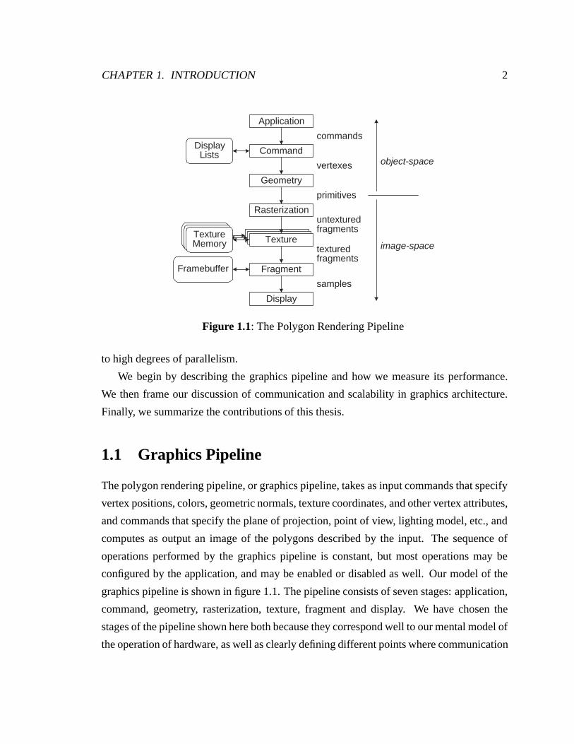
Figure 1.1: The Polygon Rendering Pipeline
to high degrees of parallelism.
We begin by describing the graphics pipeline and how we measure its performance.
We then frame our discussion of communication and scalability in graphics architecture.
Finally, we summarize the contributions of this thesis.
1.1 Graphics Pipeline
The polygon rendering pipeline, or graphics pipeline, takes as input commands that specify
vertex positions, colors, geometric normals, texture coordinates, and other vertex attributes,
and commands that specify the plane of projection, point of view, lighting model, etc., and
computes as output an image of the polygons described by the input. The sequence of
operations performed by the graphics pipeline is constant, but most operations may be
configured by the application, and may be enabled or disabled as well. Our model of the
graphics pipeline is shown in figure 1.1. The pipeline consists of seven stages: application,
command, geometry, rasterization, texture, fragment and display. We have chosen the
stages of the pipeline shown here both because they correspond well to our mental model of
the operation of hardware, as well as clearly defining different points where communication
CHAPTER 1. INTRODUCTION 3
may be used.
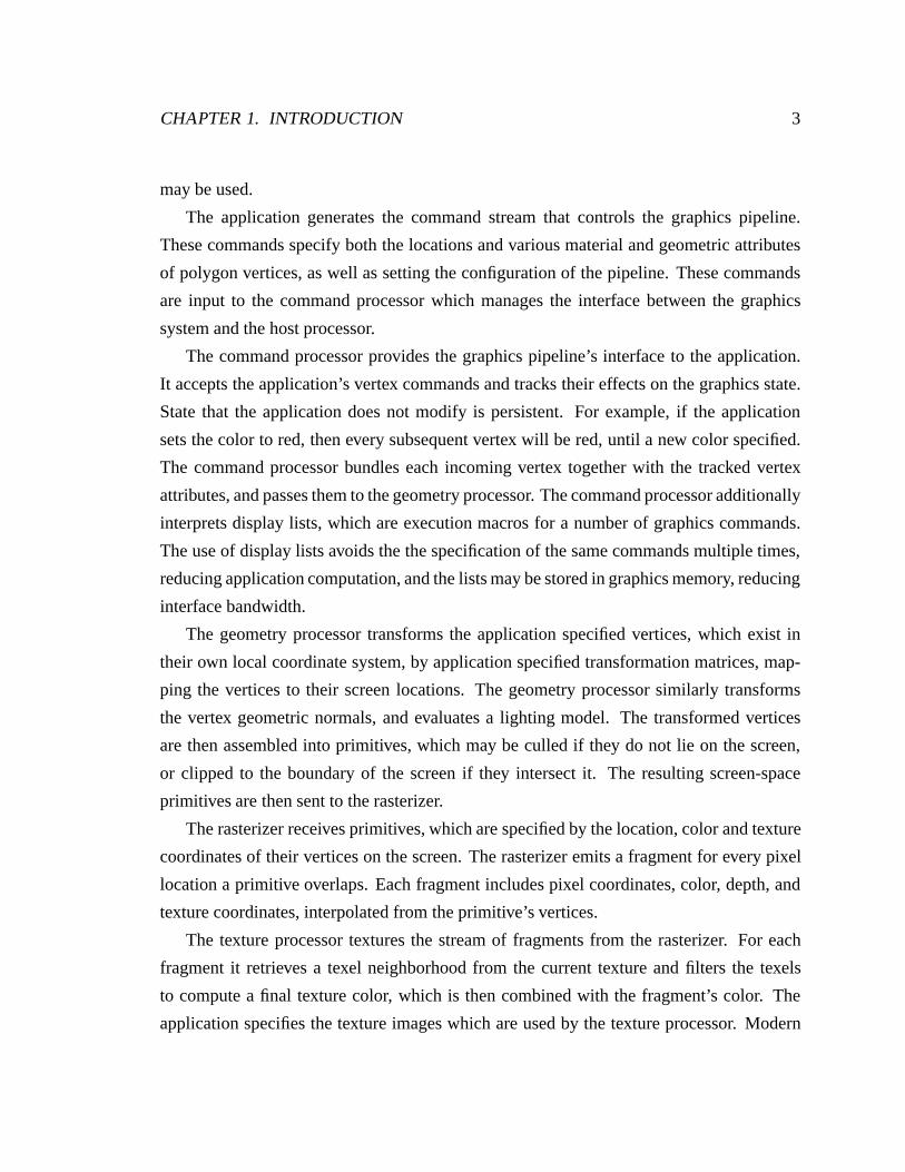
The application generates the command stream that controls the graphics pipeline.
These commands specify both the locations and various material and geometric attributes
of polygon vertices, as well as setting the configuration of the pipeline. These commands
are input to the command processor which manages the interface between the graphics
system and the host processor.
The command processor provides the graphics pipeline’s interface to the application.
It accepts the application’s vertex commands and tracks their effects on the graphics state.
State that the application does not modify is persistent. For example, if the application
sets the color to red, then every subsequent vertex will be red, until a new color specified.
The command processor bundles each incoming vertex together with the tracked vertex
attributes, and passes them to the geometry processor. The command processor additionally
interprets display lists, which are execution macros for a number of graphics commands.
The use of display lists avoids the the specification of the same commands multiple times,
reducing application computation, and the lists may be stored in graphics memory, reducing
interface bandwidth.
The geometry processor transforms the application specified vertices, which exist in
their own local coordinate system, by application specified transformation matrices, map-
ping the vertices to their screen locations. The geometry processor similarly transforms
the vertex geometric normals, and evaluates a lighting model. The transformed vertices
are then assembled into primitives, which may be culled if they do not lie on the screen,
or clipped to the boundary of the screen if they intersect it. The resulting screen-space
primitives are then sent to the rasterizer.
The rasterizer receives primitives, which are specified by the location, color and texture
coordinates of their vertices on the screen. The rasterizer emits a fragment for every pixel
location a primitive overlaps. Each fragment includes pixel coordinates, color, depth, and
texture coordinates, interpolated from the primitive’s vertices.
The texture processor textures the stream of fragments from the rasterizer. For each
fragment it retrieves a texel neighborhood from the current texture and filters the texels
to compute a final texture color, which is then combined with the fragment’s color. The
application specifies the texture images which are used by the texture processor. Modern
CHAPTER 1. INTRODUCTION 4
graphics pipelines may include multiple texture processors, with the output color of each
texture processor taken as the input color to the next. In this case the rasterizer interpolates
independent texture coordinates for each texture processor.
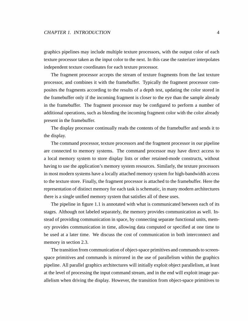
The fragment processor accepts the stream of texture fragments from the last texture
processor, and combines it with the framebuffer. Typically the fragment processor com-
posites the fragments according to the results of a depth test, updating the color stored in
the framebuffer only if the incoming fragment is closer to the eye than the sample already
in the framebuffer. The fragment processor may be configured to perform a number of
additional operations, such as blending the incoming fragment color with the color already
present in the framebuffer.
The display processor continually reads the contents of the framebuffer and sends it to
the display.
The command processor, texture processors and the fragment processor in our pipeline
are connected to memory systems. The command processor may have direct access to
a local memory system to store display lists or other retained-mode constructs, without
having to use the application’s memory system resources. Similarly, the texture processors
in most modern systems have a locally attached memory system for high-bandwidth access
to the texture store. Finally, the fragment processor is attached to the framebuffer. Here the
representation of distinct memory for each task is schematic, in many modern architectures
there is a single unified memory system that satisfies all of these uses.
The pipeline in figure 1.1 is annotated with what is communicated between each of its
stages. Although not labeled separately, the memory provides communication as well. In-
stead of providing communication in space, by connecting separate functional units, mem-
ory provides communication in time, allowing data computed or specified at one time to
be used at a later time. We discuss the cost of communication in both interconnect and
memory in section 2.3.
The transition from communication of object-space primitives and commands to screen-
space primitives and commands is mirrored in the use of parallelism within the graphics
pipeline. All parallel graphics architectures will initially exploit object parallelism, at least
at the level of processing the input command stream, and in the end will exploit image par-
allelism when driving the display. However, the transition from object-space primitives to
CHAPTER 1. INTRODUCTION 5
screen-space primitives does not dictate where the transition from object parallelism to im-
age parallelism must occur. Section 3.1 discusses the use of object-space and screen-space
parallelism in the graphics pipeline.
The pipeline we have just described has a stateful immediate-mode interface and or-
dered semantics. There are other choices that could have been made, and in section 2.1
we discuss the implications of these choices and their alternatives, both for application
programmers and hardware architects.
In a conventional microprocessor pipeline, each instruction accepts a fixed number of
inputs, typically two, and computes a constant number of outputs, typically just one. In
contrast, the computation in a graphics pipeline is much more variable. A single triangle
may be located outside of the viewing frustum, in which case it requires little computation,
and its processing ceases during the geometry stage of the pipeline, or a triangle may cover
the entire screen, in which case the rasterization and subsequent stages of the pipeline will
spend a proportionally large amount of time processing it. Generally neither the location
nor the area of a primitive on the screen is known a priori, and by extension, neither is the
amount of computation required to process the primitive.
The dynamic amount of processing required for each primitive presents the fundamen-
tal challenge to exploiting data parallelism in a graphics architecture. Although geomet-
ric processing imbalances can be significant, the primary difficulty is the widely varying
amount of rasterization processing required per primitive. In broad strokes, there are two
approaches to addressing this problem in data parallel graphics. The first, more commonly
used approach, is to partition the output space (screen) across the rasterizers. Thus large
primitives will be processed by many pipelines, and small primitives by just a single pipe-
line. The primary difficulty to these image parallel schemes is choosing a partition that
achieves a good load balance without excessive duplication of work. The second approach
is to partition the input space (primitives) across the rasterizers. Architectures based on
this approach typically assume that, given a sufficiently large number of primitives, each
pipeline will have a balanced amount of work. The main challenge of such object paral-
lel approaches is that this is in fact a poor assumption. We discuss these approaches to
parallelism, and the communication they require, in chapter 3. In chapter 4 we present an
extended taxonomy of architectures, and discuss examples of each.
CHAPTER 1. INTRODUCTION 6
Application
Command
Geometry
Rasterization
Texture
Fragment
Display
input bandwidth
pixel rate
geometry rate
texture memory
display resolution
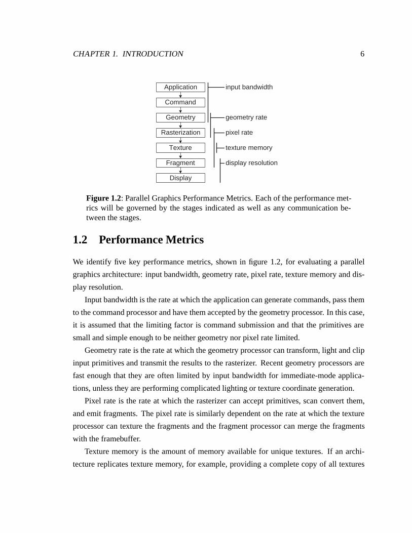
Figure 1.2: Parallel Graphics Performance Metrics. Each of the performance met-rics will be governed by the stages indicated as well as any communication be-tween the stages.
1.2 Performance Metrics
We identify five key performance metrics, shown in figure 1.2, for evaluating a parallel
graphics architecture: input bandwidth, geometry rate, pixel rate, texture memory and dis-
play resolution.
Input bandwidth is the rate at which the application can generate commands, pass them
to the command processor and have them accepted by the geometry processor. In this case,
it is assumed that the limiting factor is command submission and that the primitives are
small and simple enough to be neither geometry nor pixel rate limited.
Geometry rate is the rate at which the geometry processor can transform, light and clip
input primitives and transmit the results to the rasterizer. Recent geometry processors are
fast enough that they are often limited by input bandwidth for immediate-mode applica-
tions, unless they are performing complicated lighting or texture coordinate generation.
Pixel rate is the rate at which the rasterizer can accept primitives, scan convert them,
and emit fragments. The pixel rate is similarly dependent on the rate at which the texture
processor can texture the fragments and the fragment processor can merge the fragments
with the framebuffer.
Texture memory is the amount of memory available for unique textures. If an archi-
tecture replicates texture memory, for example, providing a complete copy of all textures
CHAPTER 1. INTRODUCTION 7
for each texture processor, then the unique texture memory is the total amount of texture
memory divided by the replication factor.
Display resolution is the resolution and number of displays which can be supported.
Each of these performance metrics is determined not only be the compute and memory
capacity of its particular stages, but also by the communication mechanisms which connect
those stages.
1.3 Communication
Communication forms the backbone of parallel graphics, allowing multiple functional units
to cooperate to render images. How various architectures use communication to distribute
the parallel computation will be our be primary means of differentiating them. Communi-
cation serves two main purposes within parallel graphics. First, it enables the fan-out and
fan-in of parallel computations. Nearly all parallel graphics architectures fan-in parallel
computation at the display – communication is used to route the parallel computation of
the frame by multiple pipelines to a display or displays. Most architectures additionally use
communication to fan-out an input serial command stream, distributing its work over the
pipelines. The second purpose of communication is to garner efficiency. Communication
helps us garner efficiency by allowing us to load-balance work across pipelines and reduce
duplication of memory and computation.
Communication allows us to balance the computational load across the various pipe-
lines so that the pipelines are uniformly utilized. Load-balancing is necessary because even
if the same number of primitives is given to every pipeline, those primitives will differ both
in the amount of geometric work required and the amount of rasterization work required.
Given that the amount of work required per primitive is generally not known a priori, the
work may either be distributed dynamically, relying on work estimators and feedback to
balance the load, or statically, relying on a statistical load balance. We will see that in
practice load-balanced static partitions are quite difficult to implement efficiently.
Communication allows us to reduce duplication of memory by, for example, partition-
ing the framebuffer among the pipelines and sorting work to the appropriate pipeline, rather
CHAPTER 1. INTRODUCTION 8
than providing a duplicate framebuffer for each pipeline. Similarly, we may choose to parti-
tion the texture memory among the pipelines in the system and communicate texture reads
between pipelines rather than replicating the texture store on each pipeline. In the same
vein, communication allows us to perform a computation once and communicate the result
to all the necessary recipients, rather than having them each perform the computation. For
example, communication between geometry and rasterization allows each primitive to be
transformed and setup only once, although multiple rasterizers may be responsible for the
computation of its fragments.
Rather than using communication to reduce duplication of memory, we can use mem-
ory to reduce communication. For example, it may be more efficient to replicate texture
memory on each pipeline, rather than sharing it over a texture memory interconnect. Simi-
larly, the application might put its commands into display lists which can be cached in the
graphics system, so the commands do not utilize the scarce host interface bandwidth, or
the host’s scarce compute cycles. In effect, memory provides communication across time,
allowing the architecture to use computations (textures, commands, etc.) at a time deferred
from their specification.
We take a unified view of both interconnect and memory as communication. An inter-
connect provides communication across space, while a memory provides communication
across time. In part, we analyze the differences in these forms of communication, and show
how they may be interchanged.
1.4 Scalability
The performance of interactive graphics architectures has been improving at phenomenal
rates over the past few decades. Not only have the speed improvements kept up with or ex-
ceeded Moore’s Law, but each successive generation of graphics architecture has expanded
the feature set. Despite these great improvements, many applications cannot run at interac-
tive rates on modern hardware. Examples include scientific visualization of large data sets,
photo-realistic rendering, low-latency virtual reality, and large-scale display systems. A
primary goal in graphics research is finding ways to push this performance envelope, from
the details of the chip architecture to the overall system architecture.
CHAPTER 1. INTRODUCTION 9
The past few years have also marked a turning point in the history of computer graphics.
Two decades ago, interactive 3D graphics systems were found only at large institutions. As
semiconductor technologies improved, graphics architects found innovative ways to place
more functionality on fewer chips, and interactive graphics workstations made their way
to the desktops of engineers. Today, the entire graphics pipeline can be placed on a single
chip and sold at a mass-market price point. Because of the enormous economies of scale
afforded by commodity parts, this trend has a significant impact on how high-end systems
must be built: it is much more cost effective to design a single low-end, high-volume system
and replicate it in an efficient manner in order to create high-end, low-volume systems.
For example, supercomputers used to be designed with unique, proprietary architectures
and esoteric technologies. As microprocessors became commodity parts, these designs
were replaced by highly parallel multiprocessor systems that made use of microprocessor
technology.
In this thesis we examine graphics architectures from a perspective of scalability. We
consider not only how well a particular implementation of an architecture works, but also
how that architecture’s performance scales with increasing parallelism. From our obser-
vations of existing architectures, we synthesize a new architecture, called “Pomegranate.”
The Pomegranate architecture, described in chapter 5, provides a way of scaling the base
unit of a single graphics pipeline to create higher performance systems, with near linear
performance increases in all of our graphics performance metrics.
In many fields, parallelism is employed not to solve the same problem faster, but instead
to solve a bigger problem at the same speed. This is particularly true of interactive computer
graphics. Humans interact well at frame rates between approximately 100Hz and 1Hz.
Above 100Hz the improved performance is not perceivable, and below 1Hz the system
loses interactivity. Thus, parallel graphics is generally used to visualize bigger problems,
rather than the same problems faster.
This has a profound effect on how parallelism is managed. If we expect a system that
is twice as large to be used to render scenes that are twice as large, then approaches which
perform broadcast communication proportional to the size of the input, either over inter-
connects or by replicating memory, have a cost that grows as O(n2) – each of n units will
require communication that scales as n. In order to be a truly scalable graphics architecture,
CHAPTER 1. INTRODUCTION 10
Pomegranate was specifically designed to avoid the use of broadcast communication, and
in chapter 7 we demonstrate its efficiency, and compare its performance to other graphics
architectures.
1.5 Summary of Original Contributions
The original contributions of this work are in two areas. First, we present an analysis of
parallel graphics architecture based on communication:
• Extended Taxonomy We present a detailed discussion of the types of communica-
tion used in parallel graphics. We distinguish four kinds of communication: sorting,
which connects object and image parallel stages, distribution, which connects object
parallel stages, routing, which connects image parallel stages, and texturing, which
connects untextured fragments with texture samples. We show that while sorting has
been the traditional focus of parallel graphics architecture, distribution, routing and
texturing are just as critical. This motivates our introduction of an extended taxon-
omy of parallel graphics architecture. Our taxonomy more accurately describes the
location of the sort, in particular distinguishing architecture which sort fragments
from those which composite images. We analyze several hardware and software
graphics architectures under our taxonomy, focusing on their use of communication
and parallelism, and the resulting ramifications on the architecture’s scalability.
• Insight to Limitations We analyze the limitations of the architectures described un-
der our taxonomy. We discuss the importance of the application visibility of work,
so that the efficiency of the graphics system will depend only on application visible
characteristics of the input. We consider the limitations of image parallelism, and
argue that deferring image parallelism until fragment processing has strong advan-
tages. We examine approaches to solving the limitations of a serial interface and
conclude that for many applications a parallel interface is the only appropriate solu-
tion. Finally, we discuss the impact of efficiently supporting texturing, and conclude
that object-parallel or coarse granularity image parallelism should be used.
CHAPTER 1. INTRODUCTION 11
Then we present Pomegranate, a new, fully scalable, graphics architecture. We origi-
nally described Pomegranate in [Eldridge et al., 2000], the description here is significantly
expanded:
• Designed for Communication Efficiency Pomegranate’s parallelism is chosen to
not require the use of broadcast communication, but only general all-to-all commu-
nication. As a result, Pomegranate requires total interconnect bandwidth proportional
to the number of pipelines. We demonstrate the achieved efficiency of Pomegranate’s
communication scheme, and discuss ways to address imbalances at high degrees of
parallelism.
• Scalable in All Performance Metrics Pomegranate provides scalable input band-
width, geometry rate, pixel rate, texture memory, and display bandwidth. Pomegran-
ate is the first parallel graphics architecture to offer scalability in all these metrics.
We show how the structure of Pomegranate’s parallelism insures this scalability, and
we present simulation results to validate our claims.
• Support for Parallel Input We support a parallel interface to the hardware that al-
lows multiple applications to submit commands simultaneously and independently to
the hardware. Familiar parallel programming primitives extend the API and express
ordering constraints between the execution of these commands. We demonstrate the
efficiency of Pomegranate’s parallel interface with parallel applications that submit
work with both partial and total orders.
• Novel Ordering Mechanisms We describe novel ordering mechanisms that we use
to provide support for the ordered semantics of a serial command stream, and for
the correct interleaving of multiple command streams under our parallel interface.
We discuss the efficiency of this approach, as well as its ultimate performance lim-
itations, which are reflected in a minimum granularity parallel work, and eventual
communication limitations at high degrees of parallelism. We consider utilizing a
dedicated communication mechanism as a possible solution to the second problem.
• Simulated Performance to 64 Pipelines We have constructed a detailed simulation
of the Pomegranate architecture. We simulate Pomegranate’s performance on three
CHAPTER 1. INTRODUCTION 12
different applications, from 1 to 64 pipelines. We demonstrate excellent scalability,
with 87% to 99% parallel efficiency on 64-pipeline systems.
• Comparison to Other Architectures By restructuring the Pomegranate simulator,
we compare Pomegranate’s performance to sort-first, sort-middle, and sort-last archi-
tectures. We find performance problems for each of these architectures on different
applications. We examine the causes of the observed performance, and discuss how
Pomegranate addresses these problems to obtain scalable performance.
We conclude by discussing design choices made in the Pomegranate architecture, and
speculating on what choices might be appropriate in the future.
Chapter 2
Graphics Pipeline
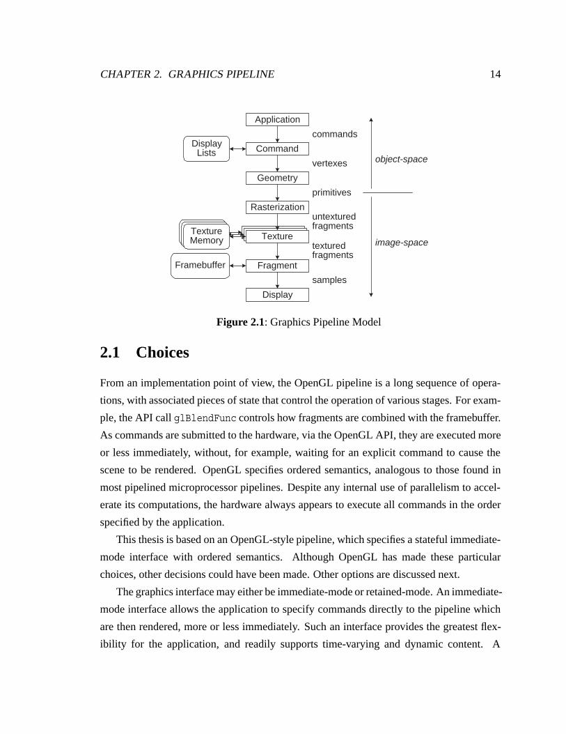
The graphics pipeline described in the introduction is an OpenGL-style pipeline. We repeat
the pipeline diagram in figure 2.1. A more detailed description of the OpenGL pipeline can
be found in the OpenGL Reference Manual [OpenGL Architecture Review Board, 1997]
and the OpenGL specification [Segal and Akeley, 1999]. We now discuss our motivation
for choosing an OpenGL pipeline model, and the alternative choices that could have been
made. We will also define our choice of terminology for describing graphics architectures.
Given our pipeline model, we provide a detailed accounting of the cost of communication
within the pipeline, and explain our extension of the graphics pipeline to accommodate a
parallel interface.
We present a baseline set of graphics pipeline functionality in this work, but our dis-
cussion and analyses do not preclude extensions and changes to the pipeline. For example,
some current graphics pipelines, and likely more pipelines in the future, include support in
the geometry processor for tessellation of input primitives. While this will change some
specific details of the pipeline operation – for example, it will affect the ratio of input
bandwidth to the number of rasterization primitives – our fundamental analysis of graphics
architectures remains the same.
13
CHAPTER 2. GRAPHICS PIPELINE 14
TextureTextureMemory TextureTextureMemory
Application
Command
Geometry
Rasterization
Fragment
Display
commands
vertexes
primitives
untexturedfragments
texturedfragments
samples
object-space
image-space
Framebuffer
DisplayLists
TextureTextureMemory
Figure 2.1: Graphics Pipeline Model
2.1 Choices
From an implementation point of view, the OpenGL pipeline is a long sequence of opera-
tions, with associated pieces of state that control the operation of various stages. For exam-
ple, the API call glBlendFunc controls how fragments are combined with the framebuffer.
As commands are submitted to the hardware, via the OpenGL API, they are executed more
or less immediately, without, for example, waiting for an explicit command to cause the
scene to be rendered. OpenGL specifies ordered semantics, analogous to those found in
most pipelined microprocessor pipelines. Despite any internal use of parallelism to accel-
erate its computations, the hardware always appears to execute all commands in the order
specified by the application.
This thesis is based on an OpenGL-style pipeline, which specifies a stateful immediate-
mode interface with ordered semantics. Although OpenGL has made these particular
choices, other decisions could have been made. Other options are discussed next.
The graphics interface may either be immediate-mode or retained-mode. An immediate-
mode interface allows the application to specify commands directly to the pipeline which
are then rendered, more or less immediately. Such an interface provides the greatest flex-
ibility for the application, and readily supports time-varying and dynamic content. A
CHAPTER 2. GRAPHICS PIPELINE 15
retained-mode interface builds an internal representation of the scene, which is then tra-
versed to generate the output image. Extensive facilities may be provided to allow the ap-
plication to edit this retained representation. Retained-mode interfaces are typically used to
attain performance higher than that which is possible through an immediate-mode interface
(due to application limited submission bandwidth) or to avoid addressing the complexities
of an immediate-mode interface. Immediate-mode interfaces may also support retained-
mode constructs, for convenience and potentially for improved performance. OpenGL
supports a retained-mode within its immediate-mode interface via display lists.
A stateful interface has the semantics of a persistent pipeline configuration, which is
modified via API calls. A stateless interface bundles the pipeline configuration with each
primitive or batch of primitives. The advantage of a stateless interface is that different
batches of primitives may be processed independently, as there can be no dependencies be-
tween them, except for their effects on the framebuffer. Stateful interfaces have the disad-
vantage that they may limit the available parallelism, by requiring that the entire command
stream be observed to know the value of any particular piece of the state.1 The advantage
of a stateful interface is that the configuration of the pipeline need only be communicated
when it is changed, rather than with each batch of primitives. The distinction we have
drawn is at the interface, but similar choices may be made within the hardware itself. For
example, many software rendering systems maintain a stateful interface for programmer
convenience, but internally operate in a stateless fashion, to avoid the difficulties of dealing
with state maintenance. Typically immediate-mode interfaces are stateful, as it provides a
natural programming model and can greatly lessen the interface bandwidth to the pipeline.
Retained-mode interfaces may be either stateful or not.
Ordered semantics have the same meaning for a graphics pipeline as they do for con-
ventional processing: commands appear to execute in the order specified. However, the
order of execution of a command is only visible via its effects on the state. Thus the pipe-
line is free to execute commands in any order, as long as the observed state of the system
is the same as if the commands had been performed in exactly the order specified.
There are three main pieces of state in the graphics pipeline: the framebuffer, the texture
1In section 8.5 we will discuss vertex arrays, which specifically relax this requirement to allow higherperformance implementations.
CHAPTER 2. GRAPHICS PIPELINE 16
memory, and the pipeline configuration. The framebuffer is probably the most challenging
piece of state to manage.2 A great deal of parallel graphics architecture has dealt with how
to provide parallel access to the framebuffer in a load-balanced fashion, while maintaining
semantics desirable to the programmer. Texture memory, although generally larger than
the framebuffer, is usually an easier management problem because it is largely read-only,
and thus the ordering problems which plague the framebuffer may be avoided by taking
some care when textures are modified. Pipeline configuration is the final piece of state
to manage. Assuming that the architects have gone to the trouble to support ordering at
the framebuffer, which falls at the end of the pipeline, then ordering the commands which
modify the pipeline configuration leading up to the framebuffer is straightforward. The
same mechanism that maintains the ordering of primitives until the framebuffer can be
reused to order the configuration commands. In fact, when these configuration commands
are not ordered by the same mechanism, but are instead executed via a sideband path, it
is typically a source of lost performance, because the pipeline must be flushed before the
commands can be executed.
When ordering is not fully supported it has typically been relaxed or eliminated at the
framebuffer, removing the guarantee that fragments are composited in the order their cor-
responding primitives were submitted. While this relaxation may be acceptable for depth-
composited rendering, it practically eliminates the possibility of supporting transparency,
and other techniques which rely on program controlled compositing order. Note that the
ordering requirements at the framebuffer are in fact fairly relaxed already. In particular, or-
der is only visible on a pixel-by-pixel basis. Thus an architecture with many image parallel
fragment processors need not coordinate the processors in general – as long as each does
its work in order, the overall set of work is done in order.
Systems with a stateless interface, or those that are stateless internally, may further
relax ordering. Such systems can carry the pipeline and texture configuration along with
each batch of primitives, and thus batches of primitives can be readily reordered. IRIS
Performer, a scene graph library built on top of OpenGL, specifically disallows particular
2Interestingly, the OpenGL graphics system specification [Segal and Akeley, 1999] describes operationsthat are performed on the framebuffer, but the framebuffer is not actually part of the graphics state. Unliketexture and the pipeline configuration, the framebuffer is always shared among all of the graphics contexts,and is thus part of the window system state.
CHAPTER 2. GRAPHICS PIPELINE 17
Geom
RastTex
Frag
Geom
RastTex
Frag
Geom
Frag Frag
pipeline
stage
processor
port
network
Cmd
App
Disp
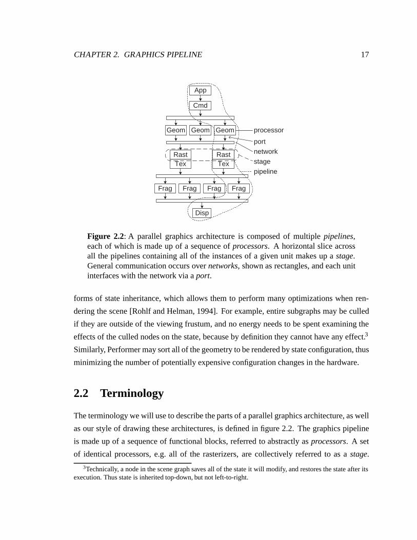
Figure 2.2: A parallel graphics architecture is composed of multiple pipelines,each of which is made up of a sequence of processors. A horizontal slice acrossall the pipelines containing all of the instances of a given unit makes up a stage.General communication occurs over networks, shown as rectangles, and each unitinterfaces with the network via a port.
forms of state inheritance, which allows them to perform many optimizations when ren-
dering the scene [Rohlf and Helman, 1994]. For example, entire subgraphs may be culled
if they are outside of the viewing frustum, and no energy needs to be spent examining the
effects of the culled nodes on the state, because by definition they cannot have any effect.3
Similarly, Performer may sort all of the geometry to be rendered by state configuration, thus
minimizing the number of potentially expensive configuration changes in the hardware.
2.2 Terminology
The terminology we will use to describe the parts of a parallel graphics architecture, as well
as our style of drawing these architectures, is defined in figure 2.2. The graphics pipeline
is made up of a sequence of functional blocks, referred to abstractly as processors. A set
of identical processors, e.g. all of the rasterizers, are collectively referred to as a stage.
3Technically, a node in the scene graph saves all of the state it will modify, and restores the state after itsexecution. Thus state is inherited top-down, but not left-to-right.
CHAPTER 2. GRAPHICS PIPELINE 18
We refer to a set of processors that together would form a serial graphics pipeline as a
pipeline, recognizing that the actual architecture may not consist of simple replications of
this pipeline. For example, there may be twice as many fragment processors as there are
rasterizers. The stages of the architecture can be interconnected in many ways, which we
represent schematically. If two units only communicate with each other, and are located in
the same package, they are abutted to show this relationship. For example, the rasterizers
and texture processors are paired in the fictitious architecture in figure 2.2. If the two units
of a pair are connected by external communication this is shown by an arrow between
them, as in the application and command processors which are connected by the host I/O
subsystem. Shared communication mechanisms, connecting one or more sources to one or
more sinks, are depicted as rectangles. We refer to such shared mechanisms as networks
and each source and sink has a port in to or out of the network.
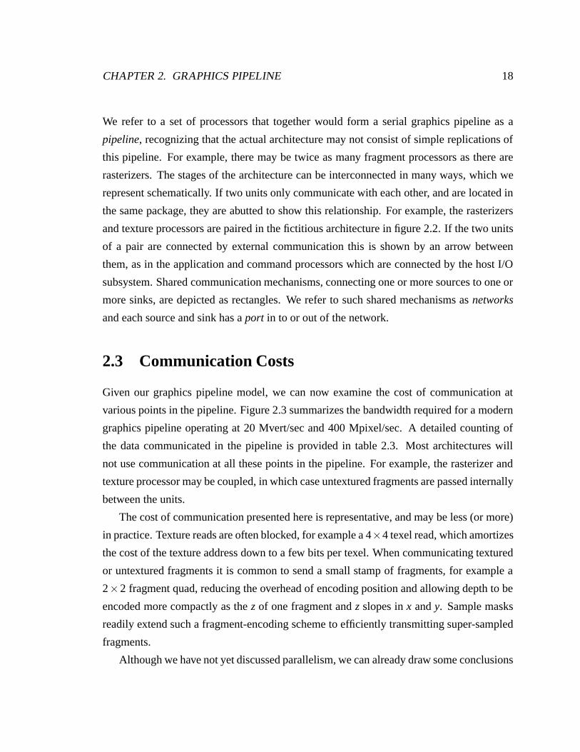
2.3 Communication Costs
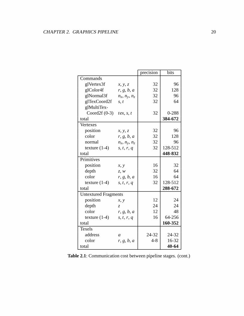
Given our graphics pipeline model, we can now examine the cost of communication at
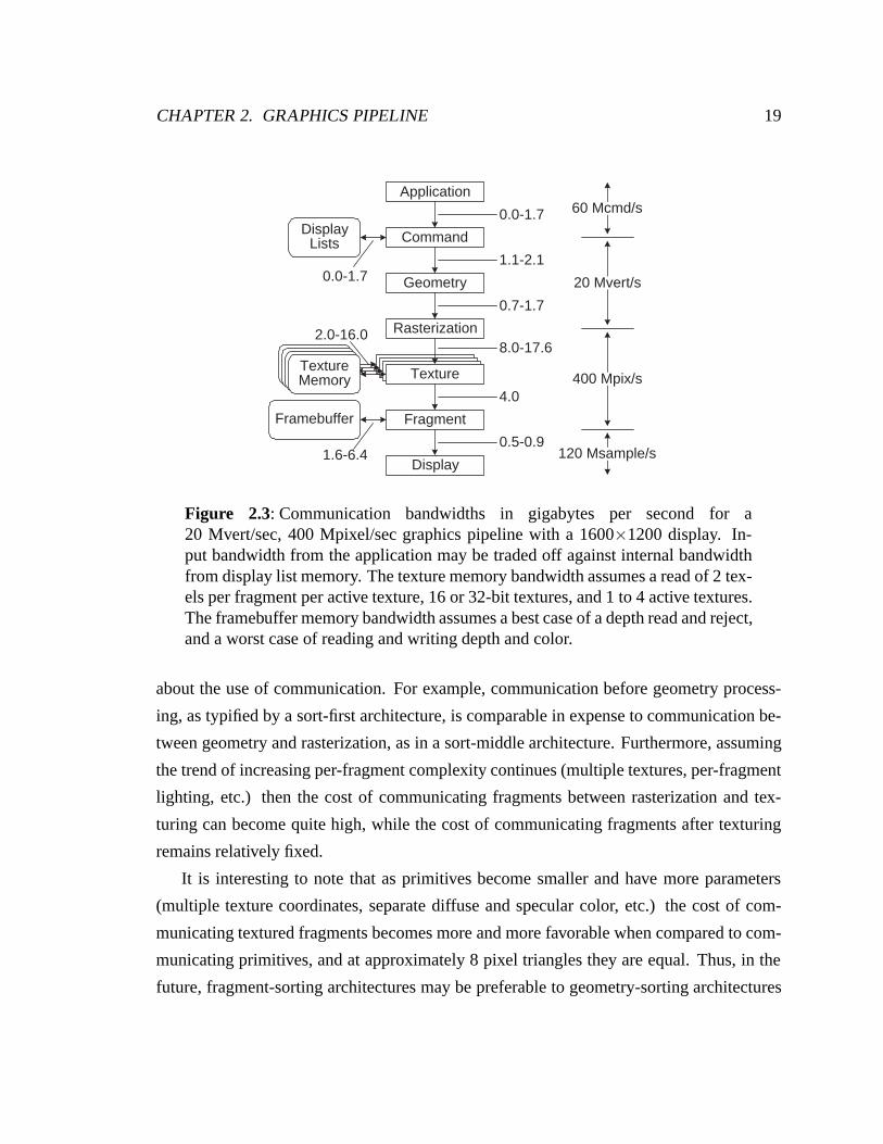
various points in the pipeline. Figure 2.3 summarizes the bandwidth required for a modern
graphics pipeline operating at 20 Mvert/sec and 400 Mpixel/sec. A detailed counting of
the data communicated in the pipeline is provided in table 2.3. Most architectures will
not use communication at all these points in the pipeline. For example, the rasterizer and
texture processor may be coupled, in which case untextured fragments are passed internally
between the units.
The cost of communication presented here is representative, and may be less (or more)
in practice. Texture reads are often blocked, for example a 4×4 texel read, which amortizes
the cost of the texture address down to a few bits per texel. When communicating textured
or untextured fragments it is common to send a small stamp of fragments, for example a
2×2 fragment quad, reducing the overhead of encoding position and allowing depth to be
encoded more compactly as the z of one fragment and z slopes in x and y. Sample masks
readily extend such a fragment-encoding scheme to efficiently transmitting super-sampled
fragments.
Although we have not yet discussed parallelism, we can already draw some conclusions
CHAPTER 2. GRAPHICS PIPELINE 19
TextureTextureMemory
20 Mvert/s
400 Mpix/s
120 Msample/s
TextureTextureMemory TextureTextureMemory
Application
Command
Geometry
Rasterization
Fragment
Display
Framebuffer
DisplayLists
TextureTextureMemory
0.0-1.7
1.1-2.1
0.7-1.7
8.0-17.6
4.0
0.5-0.91.6-6.4
2.0-16.0
0.0-1.7
60 Mcmd/s
Figure 2.3: Communication bandwidths in gigabytes per second for a20 Mvert/sec, 400 Mpixel/sec graphics pipeline with a 1600×1200 display. In-put bandwidth from the application may be traded off against internal bandwidthfrom display list memory. The texture memory bandwidth assumes a read of 2 tex-els per fragment per active texture, 16 or 32-bit textures, and 1 to 4 active textures.The framebuffer memory bandwidth assumes a best case of a depth read and reject,and a worst case of reading and writing depth and color.
about the use of communication. For example, communication before geometry process-
ing, as typified by a sort-first architecture, is comparable in expense to communication be-
tween geometry and rasterization, as in a sort-middle architecture. Furthermore, assuming
the trend of increasing per-fragment complexity continues (multiple textures, per-fragment
lighting, etc.) then the cost of communicating fragments between rasterization and tex-
turing can become quite high, while the cost of communicating fragments after texturing
remains relatively fixed.
It is interesting to note that as primitives become smaller and have more parameters
(multiple texture coordinates, separate diffuse and specular color, etc.) the cost of com-
municating textured fragments becomes more and more favorable when compared to com-
municating primitives, and at approximately 8 pixel triangles they are equal. Thus, in the
future, fragment-sorting architectures may be preferable to geometry-sorting architectures
CHAPTER 2. GRAPHICS PIPELINE 20
precision bitsCommands
glVertex3f x, y, z 32 96glColor4f r, g, b, a 32 128glNormal3f nx, ny, nz 32 96glTexCoord2f s, t 32 64glMultiTex-Coord2f (0-3) tex, s, t 32 0-288
total 384-672Vertexes
position x, y, z 32 96color r, g, b, a 32 128normal nx, ny, nz 32 96texture (1-4) s, t, r, q 32 128-512
total 448-832Primitives
position x, y 16 32depth z, w 32 64color r, g, b, a 16 64texture (1-4) s, t, r, q 32 128-512
total 288-672Untextured Fragments
position x, y 12 24depth z 24 24color r, g, b, a 12 48texture (1-4) s, t, r, q 16 64-256
total 160-352Texels
address a 24-32 24-32color r, g, b, a 4-8 16-32
total 40-64
Table 2.1: Communication cost between pipeline stages. (cont.)
CHAPTER 2. GRAPHICS PIPELINE 21
precision bitsTextured Fragments
position x, y 12 24depth z 24 24color r, g, b, a 8 32
total 80Samples
color r, g, b 8 24depth z 0-24 0-24
total 36-60
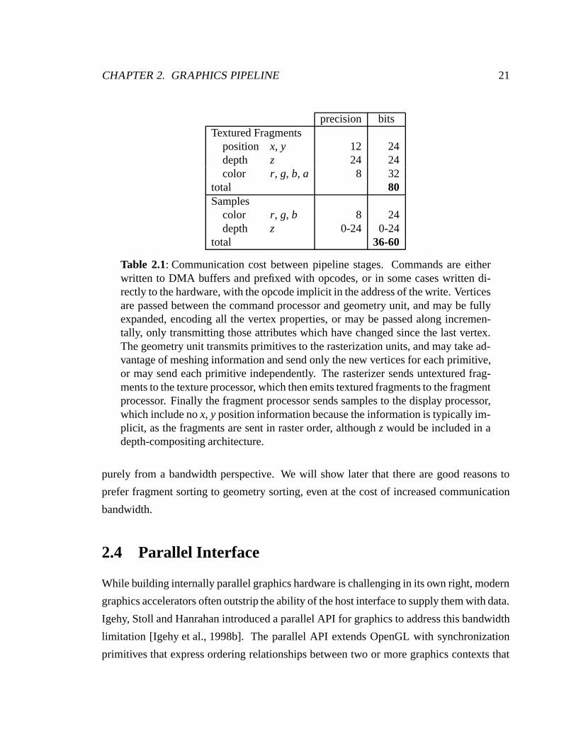
Table 2.1: Communication cost between pipeline stages. Commands are eitherwritten to DMA buffers and prefixed with opcodes, or in some cases written di-rectly to the hardware, with the opcode implicit in the address of the write. Verticesare passed between the command processor and geometry unit, and may be fullyexpanded, encoding all the vertex properties, or may be passed along incremen-tally, only transmitting those attributes which have changed since the last vertex.The geometry unit transmits primitives to the rasterization units, and may take ad-vantage of meshing information and send only the new vertices for each primitive,or may send each primitive independently. The rasterizer sends untextured frag-ments to the texture processor, which then emits textured fragments to the fragmentprocessor. Finally the fragment processor sends samples to the display processor,which include no x, y position information because the information is typically im-plicit, as the fragments are sent in raster order, although z would be included in adepth-compositing architecture.
purely from a bandwidth perspective. We will show later that there are good reasons to
prefer fragment sorting to geometry sorting, even at the cost of increased communication
bandwidth.
2.4 Parallel Interface
While building internally parallel graphics hardware is challenging in its own right, modern
graphics accelerators often outstrip the ability of the host interface to supply them with data.
Igehy, Stoll and Hanrahan introduced a parallel API for graphics to address this bandwidth
limitation [Igehy et al., 1998b]. The parallel API extends OpenGL with synchronization
primitives that express ordering relationships between two or more graphics contexts that
CHAPTER 2. GRAPHICS PIPELINE 22
glClear()glBarrierExec(1)draw opaque[1..500]glBarrierExec(1)draw transparent[1..500]glSemaphoreV(2)
glBarrierExec(1)glSwapBuffers()
glBarrierExec(1)draw opaque[501..1000]glBarrierExec(1)
glSemaphoreP(2)draw transparent[501...1000]glBarrierExec(1)
Context A Context B
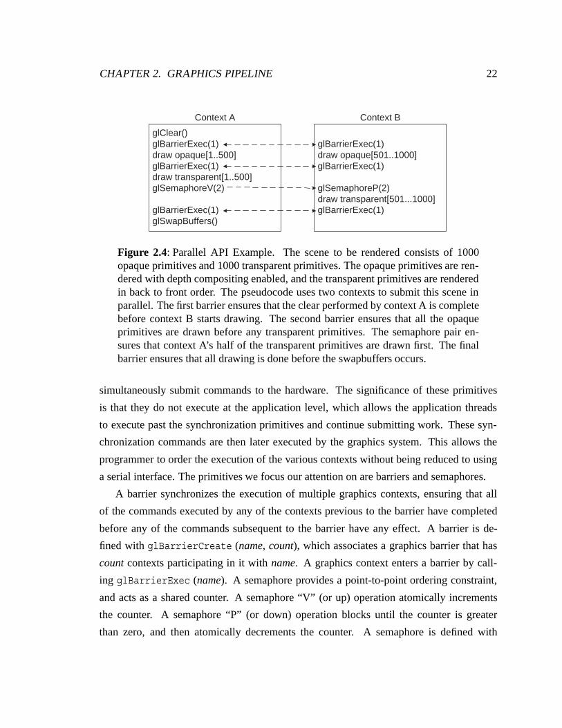
Figure 2.4: Parallel API Example. The scene to be rendered consists of 1000opaque primitives and 1000 transparent primitives. The opaque primitives are ren-dered with depth compositing enabled, and the transparent primitives are renderedin back to front order. The pseudocode uses two contexts to submit this scene inparallel. The first barrier ensures that the clear performed by context A is completebefore context B starts drawing. The second barrier ensures that all the opaqueprimitives are drawn before any transparent primitives. The semaphore pair en-sures that context A’s half of the transparent primitives are drawn first. The finalbarrier ensures that all drawing is done before the swapbuffers occurs.
simultaneously submit commands to the hardware. The significance of these primitives
is that they do not execute at the application level, which allows the application threads
to execute past the synchronization primitives and continue submitting work. These syn-
chronization commands are then later executed by the graphics system. This allows the
programmer to order the execution of the various contexts without being reduced to using
a serial interface. The primitives we focus our attention on are barriers and semaphores.
A barrier synchronizes the execution of multiple graphics contexts, ensuring that all
of the commands executed by any of the contexts previous to the barrier have completed
before any of the commands subsequent to the barrier have any effect. A barrier is de-
fined with glBarrierCreate (name, count), which associates a graphics barrier that has
count contexts participating in it with name. A graphics context enters a barrier by call-
ing glBarrierExec (name). A semaphore provides a point-to-point ordering constraint,
and acts as a shared counter. A semaphore “V” (or up) operation atomically increments
the counter. A semaphore “P” (or down) operation blocks until the counter is greater
than zero, and then atomically decrements the counter. A semaphore is defined with

CHAPTER 2. GRAPHICS PIPELINE 23
glSemaphoreCreate (name, initialCount), V’d by glSemaphoreV (name) and P’d by
glSemaphoreP (name). Figure 2.4 provides an example of the use of these primitives.
Chapter 3
Parallelism and Communication
Parallelism and communication are intimately connected. Communication allows us to
merge the parallel computation of an image to generate a display, as well as to split a
serial input to process it in parallel. We will first discuss the forms of parallelism available
in parallel graphics, and then the use of communication to allow this parallelism to be
exploited.
3.1 Parallelism
There are two broad forms of parallelism to exploit in parallel graphics:
• Task Parallelism performs some or all of the various stages of the graphics pipeline
simultaneously.
• Data Parallelism duplicates some or all of the stages of the graphics pipeline to
process multiple primitives simultaneously.
Task parallelism is the most commonly exploited form of parallelism. Because primi-
tives require varying amounts of work as they progress through the pipeline, exploiting task
parallelism requires choosing the ratio of performance between various pipeline stages.
One of the choices is the ratio of rasterization to geometry performance. For many modern
graphics pipelines the balance is approximately 20:1, in other words there are 20 pixels of
24
CHAPTER 3. PARALLELISM AND COMMUNICATION 25
rasterization performance for every 1 vertex of geometry performance. Because the com-
putation per primitive varies throughout the pipeline, and depends on characteristics of the
input not known a priori (the primitive size), the operation of pipeline will generally be
limited by a single stage, rather than taxing all pipeline stages equally. Moreover, most
scenes exhibit a skewed input distribution, with almost all of the primitives much smaller
than the balanced primitive size, and a few primitives being very large. The result can
be that while the rasterizer processes a large primitive the geometry processor sits idle,
waiting for the rasterizer to accept subsequent primitives. The affect can be mitigated by
introducing buffering between stages, particularly at those points where work may expand.
For example, SGI’s InfiniteReality includes a 65,536 vertex FIFO between the geometry
processors and the rasterization processors to allow the geometry processors to continue to
make forward progress while the rasterization processors are rasterizing a large triangle or
triangles [Montrym et al., 1997].
Although task parallelism has challenges of its own, we are primarily concerned with
the use of data parallelism. Data parallelism allows the combination of multiple graphics
pipelines to achieve higher levels of performance, limited only by the efficiency of the
resulting combined system. We can further divide data parallelism into two categories,
based on the granularity of parallelism:
• Interframe Parallelism computes multiple frames in parallel.
• Intraframe Parallelism computes a single frame in parallel.
Interframe parallelism increases frame throughput, without decreasing frame latency.
For many applications, such as rendering the frames of a movie, it may be acceptable
to not address latency. However, interactive computer graphics is generally restricted to
operate at human time scales, which limits acceptable latency to a hundred milliseconds or
less in many cases. Thus interframe parallel approaches remain limited by the performance
of a single pipeline – as soon as the rendering time for the scene on one pipeline exceeds
the user’s latency tolerance, the system ceases to scale. This generally limits such systems
to low degrees of parallelism. Despite its disadvantages, interframe parallelism has the
significant advantage of being straightforward to exploit, and in many cases may be readily
CHAPTER 3. PARALLELISM AND COMMUNICATION 26
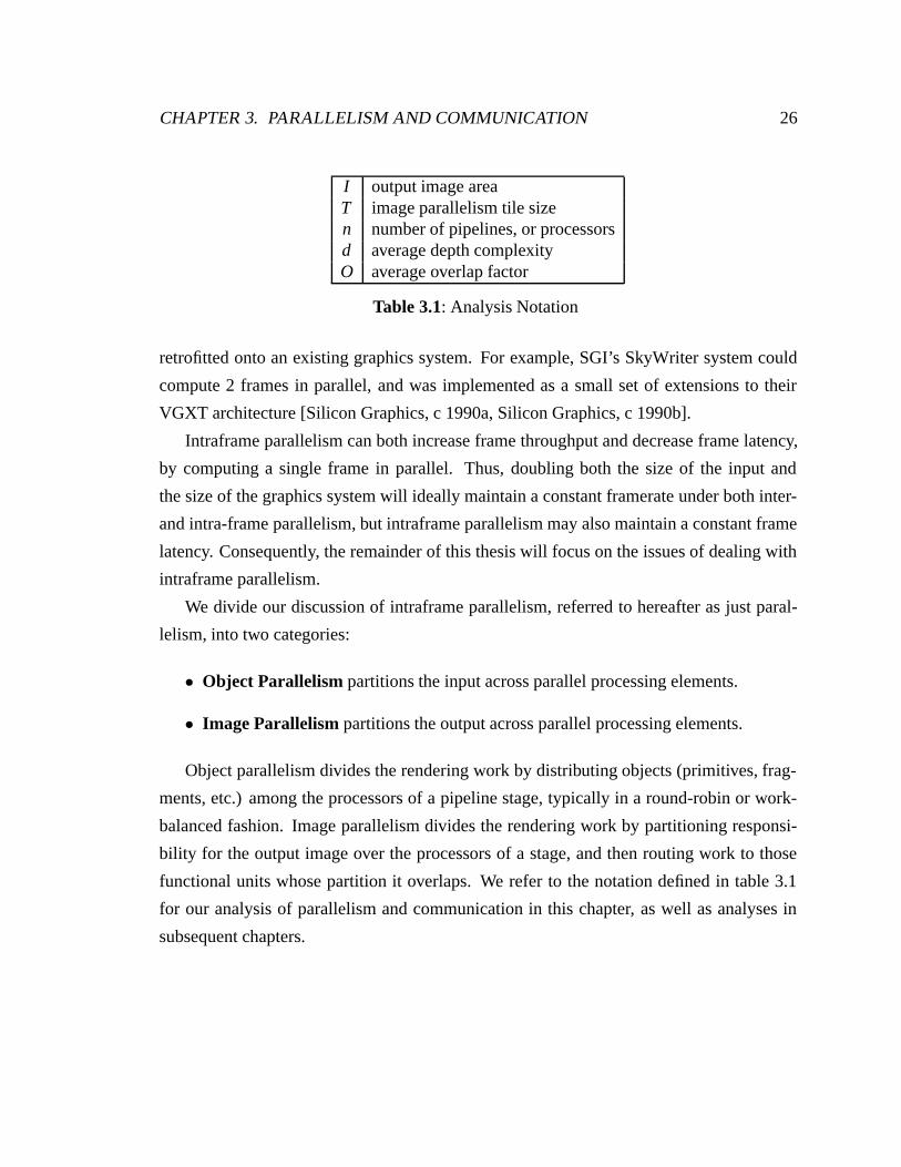
I output image areaT image parallelism tile sizen number of pipelines, or processorsd average depth complexityO average overlap factor
Table 3.1: Analysis Notation
retrofitted onto an existing graphics system. For example, SGI’s SkyWriter system could
compute 2 frames in parallel, and was implemented as a small set of extensions to their
VGXT architecture [Silicon Graphics, c 1990a, Silicon Graphics, c 1990b].
Intraframe parallelism can both increase frame throughput and decrease frame latency,
by computing a single frame in parallel. Thus, doubling both the size of the input and
the size of the graphics system will ideally maintain a constant framerate under both inter-
and intra-frame parallelism, but intraframe parallelism may also maintain a constant frame
latency. Consequently, the remainder of this thesis will focus on the issues of dealing with
intraframe parallelism.
We divide our discussion of intraframe parallelism, referred to hereafter as just paral-
lelism, into two categories:
• Object Parallelism partitions the input across parallel processing elements.
• Image Parallelism partitions the output across parallel processing elements.
Object parallelism divides the rendering work by distributing objects (primitives, frag-
ments, etc.) among the processors of a pipeline stage, typically in a round-robin or work-
balanced fashion. Image parallelism divides the rendering work by partitioning responsi-
bility for the output image over the processors of a stage, and then routing work to those
functional units whose partition it overlaps. We refer to the notation defined in table 3.1
for our analysis of parallelism and communication in this chapter, as well as analyses in
subsequent chapters.
CHAPTER 3. PARALLELISM AND COMMUNICATION 27
3.1.1 Object Parallelism
An object parallel pipeline stage partitions the input work across its processors. This parti-
tion may be done in a simple round-robin fashion, in a work-balanced fashion, or in many
other ways.
The challenge of an object parallel stage, and in general any form of parallelism, is load
imbalance. The load imbalance is the ratio of the maximum amount of work performed by
any processor in the stage, divided by the average amount of work per processor in that
stage. The load balance of an object parallel stage can be completely controlled by the
choice of work distribution. There are two obstacles to obtaining a good distribution of
work. First, it may be difficult to estimate the amount of time required for a particular
computation. Second, if the source of the work is also parallel, it may require the multiple
work sources to coordinate their distribution, although if each source individually attempts
to balance its distribution, that may be adequate.
In an architecture with ordered semantics, the user-specified order of commands must
be tracked as those commands are distributed, so the outputs of the stage may be processed
in order by subsequent stages. If the work has been distributed in a round-robin fash-
ion, it may be possible to reorder the output by duplicating the round-robin order. With
more complicated distribution schemes the ordering information may have to be explicitly
passed through the stage. The maintenance of user-specified order has led many archi-
tectures which use object parallelism to introduce a point of serialization after an object
parallel stage, in order to enforce the ordered semantics. We will see later that this point
of serialization can be expensive, although there are systems which distribute this ordering
operation.
3.1.2 Image Parallelism
An image parallel stage partitions the output work across its processors. Because the par-
tition is by image coordinates of the work, image parallelism requires that we know, at
least conservatively, where each piece of work lies on the screen. Moreover, a piece of
parallel work must be routed to all the partitions it overlaps, so, unlike object parallelism,
image parallelism can introduce duplicated communication and duplicated computation.
CHAPTER 3. PARALLELISM AND COMMUNICATION 28
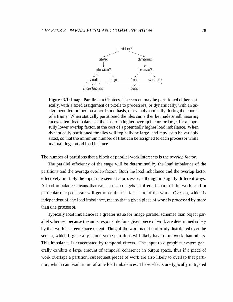
partition?
static dynamic
tile size?
small large
tile size?
fixed variable
interleaved tiled
Figure 3.1: Image Parallelism Choices. The screen may be partitioned either stat-ically, with a fixed assignment of pixels to processors, or dynamically, with an as-signment determined on a per-frame basis, or even dynamically during the courseof a frame. When statically partitioned the tiles can either be made small, insuringan excellent load balance at the cost of a higher overlap factor, or large, for a hope-fully lower overlap factor, at the cost of a potentially higher load imbalance. Whendynamically partitioned the tiles will typically be large, and may even be variablysized, so that the minimum number of tiles can be assigned to each processor whilemaintaining a good load balance.
The number of partitions that a block of parallel work intersects is the overlap factor.
The parallel efficiency of the stage will be determined by the load imbalance of the
partitions and the average overlap factor. Both the load imbalance and the overlap factor
effectively multiply the input rate seen at a processor, although in slightly different ways.
A load imbalance means that each processor gets a different share of the work, and in
particular one processor will get more than its fair share of the work. Overlap, which is
independent of any load imbalance, means that a given piece of work is processed by more
than one processor.
Typically load imbalance is a greater issue for image parallel schemes than object par-
allel schemes, because the units responsible for a given piece of work are determined solely
by that work’s screen-space extent. Thus, if the work is not uniformly distributed over the
screen, which it generally is not, some partitions will likely have more work than others.
This imbalance is exacerbated by temporal effects. The input to a graphics system gen-
erally exhibits a large amount of temporal coherence in output space, thus if a piece of
work overlaps a partition, subsequent pieces of work are also likely to overlap that parti-
tion, which can result in intraframe load imbalances. These effects are typically mitigated
CHAPTER 3. PARALLELISM AND COMMUNICATION 29
by subdividing the output space into more regions than there are processors, and assigning
multiple regions to each processor. In the limit, each tile is only a single pixel, and the load
balance can be made nearly ideal. Unfortunately, unless the granularity of work is a single
pixel as well, the price of an improved load balance is an increased overlap factor, and a
balance must be struck between these two effects. Figure 3.1 describes the choices that can
be made when partitioning image parallelism.
A detailed discussion of image tiling schemes is outside of the scope of this thesis. We
will confine our discussion to the differences in communication between these approaches,
which we broadly classify as interleaved and tiled. Interleaved parallelism uses a fine in-
terleaving of the screen across the stages, and specifically assumes that the tile size is small
enough compared to the average piece of parallel work that each piece of work overlaps all
the partitions, and consequently all work is broadcast from the previous stage. Tiled paral-
lelism typically uses a coarser tiling than interleaved parallelism, but specifically differs in
that it does not assume that each piece of work overlaps all the partitions, but instead sends
the work to only those partitions it overlaps. Chen et al. put forth models of the impact of
overlap for tiled rendering, and verify their models experimentally [Chen et al., 1998].
In 1977 Fuchs described an architecture for parallel polygon rasterization which was
based on a central unit broadcasting primitive descriptions to a set of processing elements
with finely interleaved (1 pixel granularity) responsibility for the screen [Fuchs, 1977].
Fuchs and Johnson went on to more fully describe a system based on this architecture in
1979 [Fuchs and Johnson, 1979]. They stressed the near limitless scalability of this system,
in which sets of processing boards and associated memory units could be plugged into a
backplane bus which distributes the broadcast polygons as well as the output video signal.
Although broadcast buses were de rigueur at the time, it is interesting that they made no
mention of the bandwidth of this bus, or the accompanying calculation of the maximum
rate at which primitives could be broadcast on the bus, which would obviously limit their
performance once adequate rasterization parallelism was provided.
In a 1980 paper Parke describes an architecture for tiled rasterization [Parke, 1980].
Unlike Fuchs’s use of broadcast communication, Parke uses a dynamic routing network
with “splitter” units that build a tree network. Each splitter recursively divides the screen
in half, routing input work appropriately. Although Parke’s system only had a single source
CHAPTER 3. PARALLELISM AND COMMUNICATION 30
of geometry, it was clearly on the path to a scalable switch interconnect. Parke makes a
number of trenchant observations, both about the earlier interleaved proposal of Fuchs and
about his own architecture.
Referring to Fuchs’s architecture, Parke states:
“The broadcast approach suffers from the fact that each processor must deal
with every polygon and every edge. This results in performance which ap-
proaches a polygon-edge overhead value as additional processors are added
rather than approaching zero.”
Here Parke has drawn out one of the essential limitations of all schemes which rely
on broadcast parallelism. There is a fixed cost to dealing with each piece of work, so
increasing parallelism can do no better than this fixed overhead.
Later, referring to his own architecture, Parke says:
“The splitter architecture depends on a uniformly distributed image environ-
ment. If the environment is not uniformly distributed, it is possible to saturate
a branch of the splitter tree while the other branches are idle. The worst case
is when all the image description primitives lie in a single region. For this case
only one single image processor will be active, the rest remaining idle.”
Parke identifies that the limitation of an approach with coarse-grained parallelism is
sensitivity to the image load balance. He describes a hybrid architecture to merge the
strengths of an interleaved and a tiled approach to rasterization. This architecture uses his
splitter units for the initial stages of communication, but instead of fully expanding the tree
so that each tile is the responsibility of a single processor, he truncates the tree and makes
each tile the interleaved responsibility of a number of processors. By choosing the depth
of this tree the overhead of broadcasting primitives to multiple processors can be balanced
against the potential load imbalance of tiling.
Molnar et al. provide an estimate of the overlap factor O [Molnar et al., 1994]. We
define the size of a tile as W ×H, and the average primitive bounding box as w× h, as
shown in the figure below, after the figure of Molnar et al.
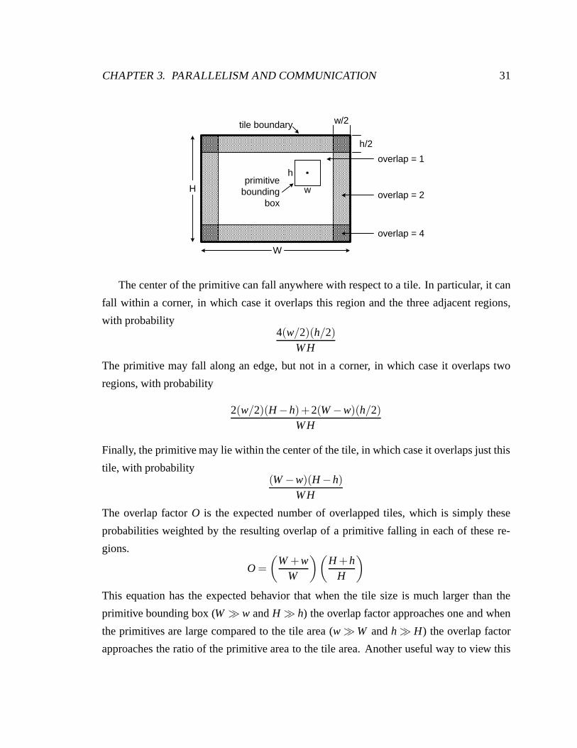
CHAPTER 3. PARALLELISM AND COMMUNICATION 31
H
W
w/2
h/2
w
h
overlap = 1
overlap = 2
overlap = 4
primitivebounding
box
tile boundary
The center of the primitive can fall anywhere with respect to a tile. In particular, it can
fall within a corner, in which case it overlaps this region and the three adjacent regions,
with probability4(w/2)(h/2)
W H
The primitive may fall along an edge, but not in a corner, in which case it overlaps two
regions, with probability
2(w/2)(H −h)+2(W −w)(h/2)W H
Finally, the primitive may lie within the center of the tile, in which case it overlaps just this
tile, with probability(W −w)(H −h)
W H
The overlap factor O is the expected number of overlapped tiles, which is simply these
probabilities weighted by the resulting overlap of a primitive falling in each of these re-
gions.
O =(
W +wW
)(H +h
H
)
This equation has the expected behavior that when the tile size is much larger than the
primitive bounding box (W � w and H � h) the overlap factor approaches one and when
the primitives are large compared to the tile area (w � W and h � H) the overlap factor
approaches the ratio of the primitive area to the tile area. Another useful way to view this
CHAPTER 3. PARALLELISM AND COMMUNICATION 32
equation is as
O =(
1+wW
)(1+
hH
)
which makes clear that all that is important is the ratio of the primitive edge to the tile edge.
If the screen size is doubled, which doubles the primitive size, and the tile size is doubled,
then obviously the overlap factor remains unchanged.
3.1.3 Object Parallel to Image Parallel Transition
The input to the graphics systems always provides us with object parallelism, as the ap-
plication is specifying primitives. Similarly, the output of the graphics system always uses
image parallelism, because the final output is a stream of pixels to a display device. Be-
tween the input and the output of the graphics system we have the flexibility to use object
parallelism and image parallelism as we see fit.
Most architectures transition exactly once from object to image parallelism, and never
back to object parallelism. This is most readily explained by the implicit maintenance of
order used in image parallel stages of the pipeline. When two image parallel stages are
connected and the partition of the output space changes between them, no special effort
needs to be made to maintain ordered semantics – as long as all the units in the first stage
did their work in order, all the units in the second stage will receive in order work. Any
interleaving of the work received by the second stage is acceptable, because the different
streams of work affect different sets of pixels, and will have no affect on each other. Al-
though this makes it most natural to use image parallelism for all stages after the sort, we
will present two variants of sort-last architectures that break this convention.
3.2 Communication
Communication moves data, in the form of vertices, primitives, textures, fragments, and
samples, to computation. To distinguish the purpose of different points of communica-
tion, we define four specific types of communication in parallel graphics: sorting, routing,
distribution and texturing. Sorting communication connects the final object parallel stage
with the initial image parallel stage. Routing communication interconnects image parallel
CHAPTER 3. PARALLELISM AND COMMUNICATION 33
stages. Distribution communication interconnects object parallel stages. Texture commu-
nication interconnects untextured fragments with texture samples.
Sorting describes the communication stage where an object parallel stage sends parallel
work to an image parallel stage and thus sorts the work to the screen. Sorting is charac-
terized by having a deterministic destination for any piece of work – only a single unit is
responsible for any given pixel. If the granularity of work being communicated is larger
than a single pixel then the communication may have more than a single destination, but
the set of destinations remains deterministic.
Routing describes communication between image parallel stages. Although both stages
are image parallel, they may use different partitions of the screen. For example, the frag-
ment processing stage may use a fine tiling of the screen, for a good static load balance,
while the display processing stage uses a coarse tiling, one monitor per display processor,
because it must get all the pixels for a single display to a common point. Because both
the source and destination for any particular piece of work are determined solely by image
coordinates, we refer to this communication as routing.
Distribution describes communication between object parallel stages. Because both
stages are object parallel, the source and destination of any piece of work may be managed
by the architecture dynamically to insure a good load balance. The term distribution is
meant as a reminder that work is being distributed at these points, presumably in a flexible
fashion.
Texture communication describes the communication of untextured fragments and tex-
ture data necessary to compute textured fragments. Unlike the other forms of commu-
nication, texture communication is disconnected from the particulars of object or image
parallelism.
We distinguish the structure of communication as being either broadcast, when each
piece of work is transmitted to an entire stage, or one-to-one, when a piece of work is
transmitted to a subset of the stage.
Broadcast communication transmits each piece of parallel work to all of the units in
the next stage, and thus requires O(n) bandwidth per port to provide scalable performance.
Additionally, each unit must be able to accept and process the aggregate command stream
of the previous stage. Although the stage will partition the work across the units, there
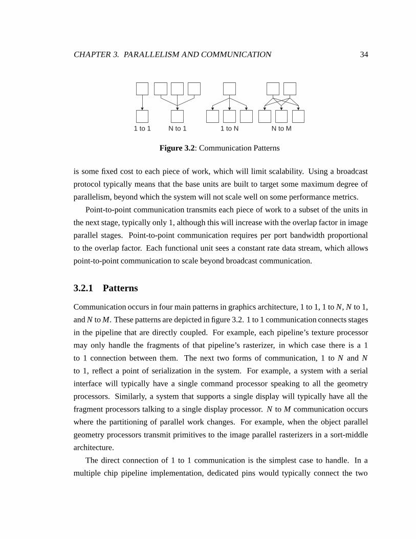
CHAPTER 3. PARALLELISM AND COMMUNICATION 34
N to 1 1 to N N to M1 to 1
Figure 3.2: Communication Patterns
is some fixed cost to each piece of work, which will limit scalability. Using a broadcast
protocol typically means that the base units are built to target some maximum degree of
parallelism, beyond which the system will not scale well on some performance metrics.
Point-to-point communication transmits each piece of work to a subset of the units in
the next stage, typically only 1, although this will increase with the overlap factor in image
parallel stages. Point-to-point communication requires per port bandwidth proportional
to the overlap factor. Each functional unit sees a constant rate data stream, which allows
point-to-point communication to scale beyond broadcast communication.
3.2.1 Patterns
Communication occurs in four main patterns in graphics architecture, 1 to 1, 1 to N, N to 1,
and N to M. These patterns are depicted in figure 3.2. 1 to 1 communication connects stages
in the pipeline that are directly coupled. For example, each pipeline’s texture processor
may only handle the fragments of that pipeline’s rasterizer, in which case there is a 1
to 1 connection between them. The next two forms of communication, 1 to N and N
to 1, reflect a point of serialization in the system. For example, a system with a serial
interface will typically have a single command processor speaking to all the geometry
processors. Similarly, a system that supports a single display will typically have all the
fragment processors talking to a single display processor. N to M communication occurs
where the partitioning of parallel work changes. For example, when the object parallel
geometry processors transmit primitives to the image parallel rasterizers in a sort-middle
architecture.
The direct connection of 1 to 1 communication is the simplest case to handle. In a
multiple chip pipeline implementation, dedicated pins would typically connect the two
CHAPTER 3. PARALLELISM AND COMMUNICATION 35
functional units. If the two units are contained in the same package then the connection is
even more straightforward.
The serialization represented by 1 to N or N to 1 communication may have performance
ramifications for the architecture (e.g. the system lacks adequate input bandwidth for scal-
able performance), however, the communication mechanism itself is not the performance
limiting factor, but rather the single unit through which all the work is serialized. Because
a single point is responsible for either sourcing or sinking all of the communication on the
channel, increasing N will further divide the load across the pipelines, but will not increase
the per-port cost of the channel. One simple implementation of a 1 to N or N to 1 channel
with linear cost is a point-to-point ring.
The challenging pattern is N to M communication. When multiple sources can commu-
nicate with multiple destinations, difficult issues arise in building a scalable communication
medium. Adding an additional ∆M or ∆N requires that the aggregate bandwidth of the net-
work increase to support the additional units. We now discuss the types of communication
used in parallel graphics architecture.
3.2.2 Networks
Communication can be supported on a variety of networks. We will focus on bus, ring
and multi-stage indirect networks (MINs). These networks are shown schematically in
figure 3.3. Duato, Yalmanchili and Ni are one source for a more detailed examination of
these and other networks [Duato et al., 1997].
A bus is a shared communication channel. The bus may only be in use by a single
source at a time, and thus requires O(n) bandwidth to support n sources. Moreover, each
destination must support the full O(n) bandwidth of the bus. Thus the per-port cost is O(n)
and the total bus cost is O(n2). The primary advantage of a bus is that, although one-
to-one communication is very inefficient, broadcast communication is no more expensive.
Additionally, arbitration for the bus provides a natural point of serialization, which can
provide a convenient mechanism for enforcing the application specified command order.
The disadvantage of a bus is that it is difficult to scale, both architecturally and electrically.
Buses are architecturally difficult to scale because each source can only fairly occupy the
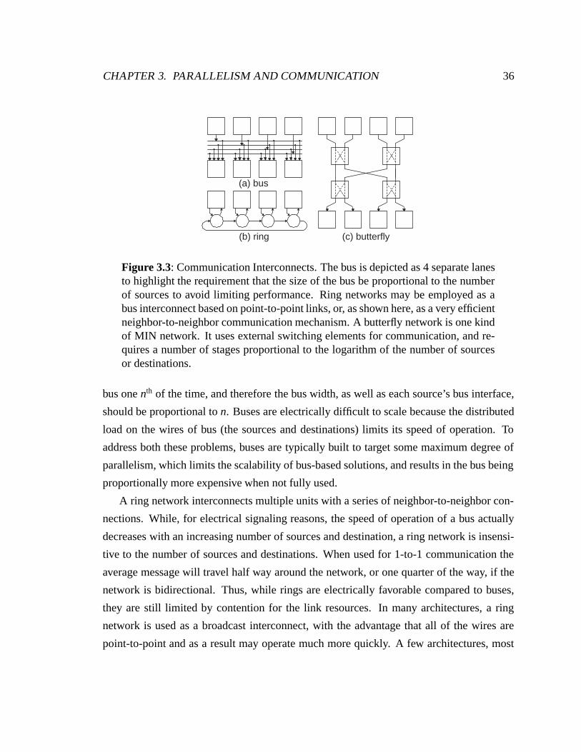
CHAPTER 3. PARALLELISM AND COMMUNICATION 36
(a) bus
(b) ring (c) butterfly
Figure 3.3: Communication Interconnects. The bus is depicted as 4 separate lanesto highlight the requirement that the size of the bus be proportional to the numberof sources to avoid limiting performance. Ring networks may be employed as abus interconnect based on point-to-point links, or, as shown here, as a very efficientneighbor-to-neighbor communication mechanism. A butterfly network is one kindof MIN network. It uses external switching elements for communication, and re-quires a number of stages proportional to the logarithm of the number of sourcesor destinations.
bus one nth of the time, and therefore the bus width, as well as each source’s bus interface,
should be proportional to n. Buses are electrically difficult to scale because the distributed
load on the wires of bus (the sources and destinations) limits its speed of operation. To
address both these problems, buses are typically built to target some maximum degree of
parallelism, which limits the scalability of bus-based solutions, and results in the bus being
proportionally more expensive when not fully used.
A ring network interconnects multiple units with a series of neighbor-to-neighbor con-
nections. While, for electrical signaling reasons, the speed of operation of a bus actually
decreases with an increasing number of sources and destination, a ring network is insensi-
tive to the number of sources and destinations. When used for 1-to-1 communication the
average message will travel half way around the network, or one quarter of the way, if the
network is bidirectional. Thus, while rings are electrically favorable compared to buses,
they are still limited by contention for the link resources. In many architectures, a ring
network is used as a broadcast interconnect, with the advantage that all of the wires are
point-to-point and as a result may operate much more quickly. A few architectures, most
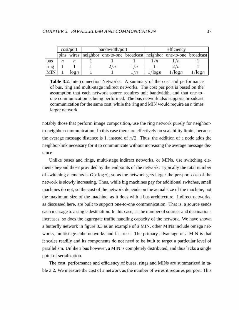
CHAPTER 3. PARALLELISM AND COMMUNICATION 37
cost/port bandwidth/port efficiencypins wires neighbor one-to-one broadcast neighbor one-to-one broadcast
bus n n 1 1 1 1/n 1/n 1ring 1 1 1 2/n 1/n 1 2/n 1MIN 1 logn 1 1 1/n 1/logn 1/logn 1/logn
Table 3.2: Interconnection Networks. A summary of the cost and performanceof bus, ring and multi-stage indirect networks. The cost per port is based on theassumption that each network source requires unit bandwidth, and that one-to-one communication is being performed. The bus network also supports broadcastcommunication for the same cost, while the ring and MIN would require an n timeslarger network.
notably those that perform image composition, use the ring network purely for neighbor-
to-neighbor communication. In this case there are effectively no scalability limits, because
the average message distance is 1, instead of n/2. Thus, the addition of a node adds the
neighbor-link necessary for it to communicate without increasing the average message dis-
tance.
Unlike buses and rings, multi-stage indirect networks, or MINs, use switching ele-
ments beyond those provided by the endpoints of the network. Typically the total number
of switching elements is O(n logn), so as the network gets larger the per-port cost of the
network is slowly increasing. Thus, while big machines pay for additional switches, small
machines do not, so the cost of the network depends on the actual size of the machine, not
the maximum size of the machine, as it does with a bus architecture. Indirect networks,
as discussed here, are built to support one-to-one communication. That is, a source sends
each message to a single destination. In this case, as the number of sources and destinations
increases, so does the aggregate traffic handling capacity of the network. We have shown
a butterfly network in figure 3.3 as an example of a MIN, other MINs include omega net-
works, multistage cube networks and fat trees. The primary advantage of a MIN is that
it scales readily and its components do not need to be built to target a particular level of
parallelism. Unlike a bus however, a MIN is completely distributed, and thus lacks a single
point of serialization.
The cost, performance and efficiency of buses, rings and MINs are summarized in ta-
ble 3.2. We measure the cost of a network as the number of wires it requires per port. This
CHAPTER 3. PARALLELISM AND COMMUNICATION 38
captures both the number of pins it requires, as well as the cost of switching stages incurred
in MIN networks. The cost per port assumes the network connects n sources with n desti-
nations. Thus, for example, the cost per port of a bus is O(n), because each source emits
unit bandwidth, and they must time-multiplex the bus. The bandwidth per port represents
the raw communication capability of each interconnect. The efficiency is the bandwidth
per cost, and is probably the most useful measure of a network. The ring network has the
best efficiency for neighbor-to-neighbor communication, which is not surprising, given its
construction. The bus and ring networks have similar efficiency for broadcast communica-
tion, although for the electrical reasons we briefly mentioned, the use of a ring is probably
preferable. Finally, the MIN has the best efficiency for one-to-one communication, which
we will argue later is the essential communication structure for scalable graphics architec-
tures.
3.2.3 Memory
Communication classically moves data from one place to another over an interconnect. If
we consider movement of data from one time to another as communication, then mem-
ory is just another way to communicate. In fact, the similarity between interconnect and
memory as communication is quite strong, particularly in modern architectures. The price
determining factor in graphics architectures has shifted from silicon area to package size,
or number of pins. Modern high-speed interconnects and high-speed memories have com-
parable bandwidth per pin (on the order of 1 Gbit/sec), so, at least to first order, the cost of
these forms of communication is equivalent. Additionally, both memory and interconnect
typically trade increased latency and increased transaction size for increased throughput.
In many cases these two forms of communication, interconnect and memory, are inter-
changeable. For example, texture can be replicated across the texture processors, providing
communication by memory, or the texture can be distributed across the texture processors,
and communicated via an interconnect. We consider three broad issues in dealing with
memory in graphics systems: tolerating the latency of the memory system, trading repli-
cation of memory against communication, and caching memory to avoid more expensive
memory accesses.
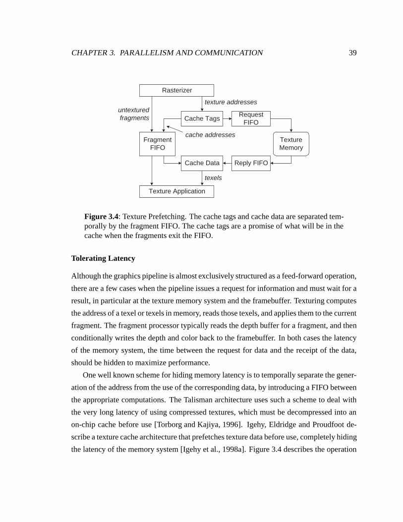
CHAPTER 3. PARALLELISM AND COMMUNICATION 39
FragmentFIFO
Cache TagsRequest
FIFO
Reply FIFOCache Data
Rasterizer
Texture Application
TextureMemory
texture addressesuntexturedfragments
cache addresses
texels
Figure 3.4: Texture Prefetching. The cache tags and cache data are separated tem-porally by the fragment FIFO. The cache tags are a promise of what will be in thecache when the fragments exit the FIFO.
Tolerating Latency
Although the graphics pipeline is almost exclusively structured as a feed-forward operation,
there are a few cases when the pipeline issues a request for information and must wait for a
result, in particular at the texture memory system and the framebuffer. Texturing computes
the address of a texel or texels in memory, reads those texels, and applies them to the current
fragment. The fragment processor typically reads the depth buffer for a fragment, and then
conditionally writes the depth and color back to the framebuffer. In both cases the latency
of the memory system, the time between the request for data and the receipt of the data,
should be hidden to maximize performance.
One well known scheme for hiding memory latency is to temporally separate the gener-
ation of the address from the use of the corresponding data, by introducing a FIFO between
the appropriate computations. The Talisman architecture uses such a scheme to deal with
the very long latency of using compressed textures, which must be decompressed into an
on-chip cache before use [Torborg and Kajiya, 1996]. Igehy, Eldridge and Proudfoot de-
scribe a texture cache architecture that prefetches texture data before use, completely hiding
the latency of the memory system [Igehy et al., 1998a]. Figure 3.4 describes the operation
CHAPTER 3. PARALLELISM AND COMMUNICATION 40
of their architecture. McCormack et al. describe a similar texture read architecture imple-
mented in Neon [McCormack et al., 1998].
It is simpler to tolerate the latency of the texture memory system than that of the frame-
buffer, because texture accesses are almost exclusively reads. Framebuffer operations are
by nature read-modify-writes, and without some care there is a read-after-write hazard in
any system that keeps multiple fragments in flight. For example, if two fragments are
destined for the same framebuffer location and the depth test is enabled, then the second
fragment should only be written to the framebuffer if it passes the depth test after the first
fragment has either been written to the framebuffer or rejected. If the depth read for the
second fragment occurs before the conditional write of the first fragment, then the sec-
ond fragment may be incorrectly composited. This difficulty is generally addressed with
some sort of scoreboard mechanism. McCormack et al. describe Neon’s scheduling of 8-
fragment batch reads to the memory, with the proviso that none of the fragments in the batch
overlap [McCormack et al., 1998]. As soon as a fragment overlaps a fragment already in
the batch the entire batch is processed, and a new batch is started with the formerly con-
flicting fragment. Owens et al. describe a clever scheme that allows them to schedule very
large framebuffer reads (hundreds of fragments) efficiently [Owens et al., 2000].
Replication
The choice of whether to structure communication as interconnect or memory is typically
an economic one. The cost of replicating memory is that either the replicated resource
will not scale in capacity, in which case the cost of the memory is O(n), or if the unique
memory does scale with n, the cost of memory is O(n2). The cost of sharing memory
is the engineering effort and expense of providing an interconnect to route memory reads
and writes between processors and memories. Of course, this form of communication is
often provided – the sort in parallel graphics corresponds to exactly this communication: it
routes work to the image parallel processor which owns the corresponding partition of the
framebuffer.
The classical use of replicated memory to replace communication is the texture memory
subsystem. For example, SGI’s RealityEngine [Akeley, 1993] provides a complete copy of
CHAPTER 3. PARALLELISM AND COMMUNICATION 41
the texture memory for each fragment generator (a combined rasterizer and texture proces-
sor in our terminology). Each raster memory board consists of 5 fragment generators, and a
full-up system with 4 raster memory boards would contain 20 complete copies of the texture
memory. While providing ready communication, the downside to this replication is that an
increase in the effective texture memory is 20 times more expensive than if the texture
memory were shared. InfiniteReality uses a single fragment generator per raster memory
board, in large part to reduce the duplication of texture memory [Montrym et al., 1997].
The alternative to replicating texture memory is to share it. Igehy, Eldridge and Hanrahan
have studied the practicality of shared texture memory schemes and have found that care-
ful layout of the texture data, so that memory accesses are well distributed over all of the
memories, yields excellent results [Igehy et al., 1999]. The disadvantage to sharing texture
memory is that it is potentially the highest bandwidth point in the system, and designing an
interconnect to handle that bandwidth may be challenging.
Another use of replicated memory is found in sort-last image composition architectures.
These architectures replicate the framebuffer per pipeline, transforming the traditional sort
in graphics architecture into an image compositing operation. The advantage of this ex-
change is two-fold. First, in systems where the depth complexity exceeds the number of
pipelines, the total communication to generate the output image is O(nI) instead of O(dI).
Second, the general communication of sorting commands, primitives or fragments to the
appropriate image parallel unit can be replaced by the regular communication of composit-
ing images, which is potentially more easily implemented. For example, PixelFlow uses a
pipelined image compositing network, and reduces the majority of the communication in
the system to neighbor-to-neighbor communication [Molnar et al., 1992].
Caching
Caching is often combined with memory systems, substituting local memory accesses for
remote memory accesses, in much the same way memory can be substituted for inter-
connect. If we consider the memory as a separate unit from the processor to which it is
attached, then they are interconnected by a network (the memory interface), and the cache
turns interconnect-based communication (using the memory interface) into memory ac-
cesses.
CHAPTER 3. PARALLELISM AND COMMUNICATION 42
All modern graphics accelerators use caching to minimize texture memory bandwidth.
SGI’s InfiniteReality graphics system uses a simple request-merging scheme to capture the
redundant memory accesses between neighboring fragments, in effect the smallest possi-
ble cache [Montrym et al., 1997]. Digital’s Neon uses a 2048 byte texel cache, divided
into 8 caches, one per memory interface [McCormack et al., 1998]. Although unpublished,
numerous consumer graphics accelerators reportedly use multiple kilobyte caches. Data
from Igehy et al. demonstrate the effectiveness of reducing texture memory bandwidth
with caching in systems which employ serial and parallel rasterization [Igehy et al., 1998a,
Igehy et al., 1999]. Hakura and Gupta studied the choice of rasterization algorithm and
texture cache organization [Hakura and Gupta, 1997]. Cox, Bhandari and Shantz exam-
ined including a second-level cache to capture interframe texture locality [Cox et al., 1998].
Vartanian, Bechennec and Drach-Temam have examined the impact of tiled rasterization
patterns in a sort-middle architecture [Vartanian et al., 2000], and the efficiency of parallel
texture caching [Vartanian et al., 1998].
While texture caches are dynamically scheduled caches, retained-mode interfaces ex-
pose to the programmer a statically schedulable cache. If the application has data which
will be rendered multiple times without modification, the programmer can choose to en-
capsulate that data in a display list, with the advantage that the data may be cached in a
display list memory local to the graphics system. Thus display lists can turn communica-
tion between the application and the graphics system into local memory references. This
has benefit of not only conserving host interface bandwidth, which is often a very limited
resource, but also of conserving the host processor’s computation.
Chapter 4
Taxonomy and Architectures
Graphics architectures are traditionally classified by the point in the pipeline where they
transition from object to image parallelism. This transition is termed the “sort”, because
it sorts work based on its screen-space location. The sort can occur between any of the
pipeline stages, as shown in figure 4.1. We distinguish four unique sorting architectures:
sort-first, sort-middle, sort-last fragment and sort-last image composition.
Sort-first architectures sort before geometry processing. The use of image parallelism
for the geometry processing means that the command processor must transform the input
vertices, or groups of input vertices, to determine which geometry processors are responsi-
ble for their processing. Sort-first architectures typically subdivide the screen into relatively
large tiles to reduce the overlap factor of primitive groups. A finely interleaved sort-first
architecture would amount to broadcasting the input command stream across all of the
pipelines, essentially the simplest possible sort.
Sort-middle architectures sort between geometry processing and rasterization. The ge-
ometry processor either transmits individual vertices with meshing information to the ras-
terizers, or entire primitives, which may already be setup for rasterization. Sort-middle
architectures, particularly hardware implementations, typically use interleaved image par-
allelism (sort-middle interleaved), insuring an excellent static load balance, at the expense
of broadcasting primitives between geometry and rasterization. Sort-middle architectures
43
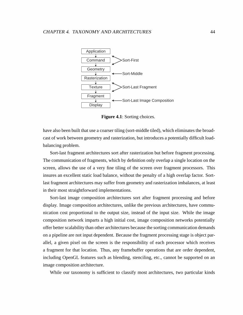
CHAPTER 4. TAXONOMY AND ARCHITECTURES 44
Application
Command
Geometry
Rasterization
Texture
Fragment
Display
Sort-First
Sort-Middle
Sort-Last Fragment
Sort-Last Image Composition
Figure 4.1: Sorting choices.
have also been built that use a coarser tiling (sort-middle tiled), which eliminates the broad-
cast of work between geometry and rasterization, but introduces a potentially difficult load-
balancing problem.
Sort-last fragment architectures sort after rasterization but before fragment processing.
The communication of fragments, which by definition only overlap a single location on the
screen, allows the use of a very fine tiling of the screen over fragment processors. This
insures an excellent static load balance, without the penalty of a high overlap factor. Sort-
last fragment architectures may suffer from geometry and rasterization imbalances, at least
in their most straightforward implementations.
Sort-last image composition architectures sort after fragment processing and before
display. Image composition architectures, unlike the previous architectures, have commu-
nication cost proportional to the output size, instead of the input size. While the image
composition network imparts a high initial cost, image composition networks potentially
offer better scalability than other architectures because the sorting communication demands
on a pipeline are not input dependent. Because the fragment processing stage is object par-
allel, a given pixel on the screen is the responsibility of each processor which receives
a fragment for that location. Thus, any framebuffer operations that are order dependent,
including OpenGL features such as blending, stenciling, etc., cannot be supported on an
image composition architecture.
While our taxonomy is sufficient to classify most architectures, two particular kinds
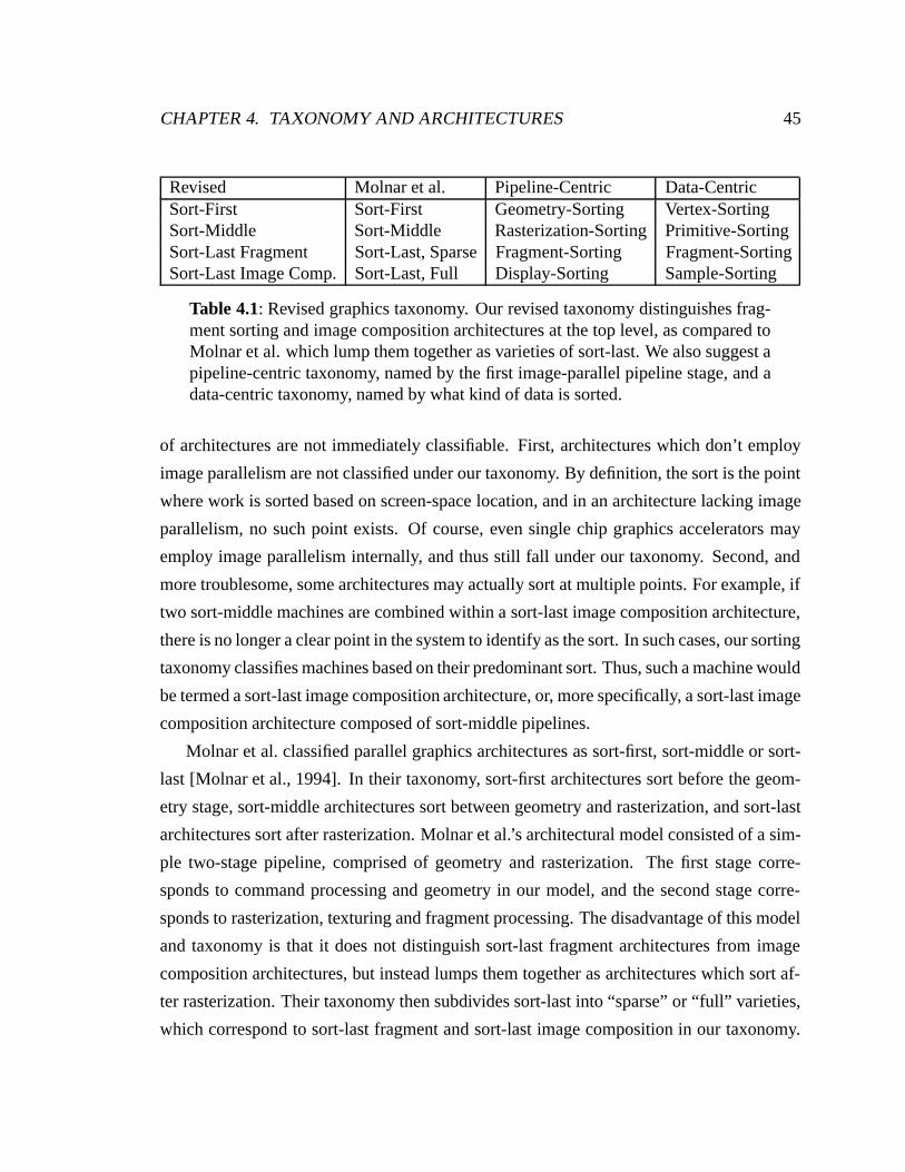
CHAPTER 4. TAXONOMY AND ARCHITECTURES 45
Revised Molnar et al. Pipeline-Centric Data-CentricSort-First Sort-First Geometry-Sorting Vertex-SortingSort-Middle Sort-Middle Rasterization-Sorting Primitive-SortingSort-Last Fragment Sort-Last, Sparse Fragment-Sorting Fragment-SortingSort-Last Image Comp. Sort-Last, Full Display-Sorting Sample-Sorting
Table 4.1: Revised graphics taxonomy. Our revised taxonomy distinguishes frag-ment sorting and image composition architectures at the top level, as compared toMolnar et al. which lump them together as varieties of sort-last. We also suggest apipeline-centric taxonomy, named by the first image-parallel pipeline stage, and adata-centric taxonomy, named by what kind of data is sorted.
of architectures are not immediately classifiable. First, architectures which don’t employ
image parallelism are not classified under our taxonomy. By definition, the sort is the point
where work is sorted based on screen-space location, and in an architecture lacking image
parallelism, no such point exists. Of course, even single chip graphics accelerators may
employ image parallelism internally, and thus still fall under our taxonomy. Second, and
more troublesome, some architectures may actually sort at multiple points. For example, if
two sort-middle machines are combined within a sort-last image composition architecture,
there is no longer a clear point in the system to identify as the sort. In such cases, our sorting
taxonomy classifies machines based on their predominant sort. Thus, such a machine would
be termed a sort-last image composition architecture, or, more specifically, a sort-last image
composition architecture composed of sort-middle pipelines.
Molnar et al. classified parallel graphics architectures as sort-first, sort-middle or sort-
last [Molnar et al., 1994]. In their taxonomy, sort-first architectures sort before the geom-
etry stage, sort-middle architectures sort between geometry and rasterization, and sort-last
architectures sort after rasterization. Molnar et al.’s architectural model consisted of a sim-
ple two-stage pipeline, comprised of geometry and rasterization. The first stage corre-
sponds to command processing and geometry in our model, and the second stage corre-
sponds to rasterization, texturing and fragment processing. The disadvantage of this model
and taxonomy is that it does not distinguish sort-last fragment architectures from image
composition architectures, but instead lumps them together as architectures which sort af-
ter rasterization. Their taxonomy then subdivides sort-last into “sparse” or “full” varieties,
which correspond to sort-last fragment and sort-last image composition in our taxonomy.
CHAPTER 4. TAXONOMY AND ARCHITECTURES 46
This implies that fragment sorting architectures and image composition architectures are
more closely related than they actually are, and that fragment sorting suffers the disadvan-
tages of image composition architectures. We compare our revised taxonomy with that of
Molnar et al., as well as our suggestions for pipeline-centric and data-centric taxonomies,
in table 4.1.
For the purposes of the taxonomy, we do not consider where texturing occurs. For
many current architectures texturing is coupled with rasterization, although historically it
has also been coupled with fragment processing. In some cases the texturing unit was
relocated in the pipeline and performed early, as part of geometry processing, or deferred,
and performed after fragment processing.
We now examine a number of parallel graphics architectures, from the perspectives of
how they employ parallelism and communication, as well as the limits to their parallelism.
Of course, in many cases these architectures were constructed as point solutions, and were
not intended to be deployed with differing degrees of parallelism. It is still interesting to
examine the scalability of these architectures, in order to understand the ultimate limits to
their applicability. Table 4.6 on page 67 summarizes the architectures we discuss, along
with many architectures not specifically examined in the text.
4.1 Sort-First
Sort-first has historically been the least explored architecture for parallel graphics. One
of the principal difficulties of sort-first is partitioning the image over the pipelines. If an
interleaved partition of the framebuffer is used, then every geometry processor handles
every primitive, and it would have been simpler to construct a sort-middle architecture
with a single geometry processor that then fans out to all the rasterizers. Given that sort-
first must tile the image, picking an efficient tile size is critical. Smaller tiles will yield
a better load balance, but will increase the overlap factor. Larger tiles reduce the overlap
factor, but require a good work estimator to insure a balanced distribution of work. Mueller
has studied different static and dynamic partitioning schemes for retained-mode sort-first
architectures [Mueller, 1995] and determined that a subdivision of the screen which gives
each pipeline 10 or more tiles provides a good static load balance. However, as we decrease
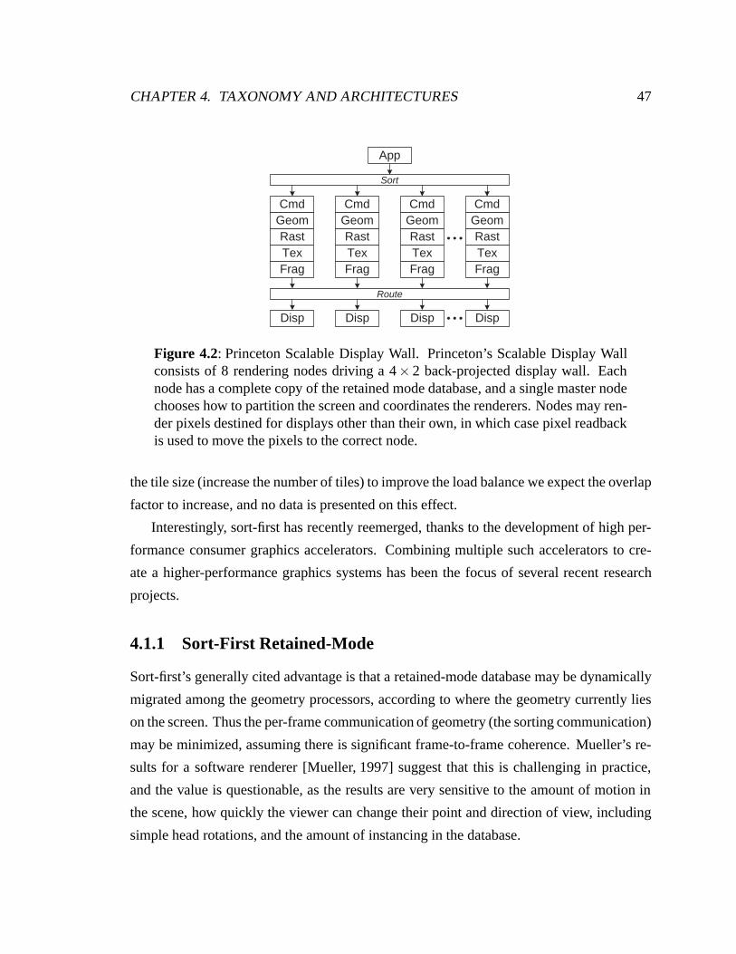
CHAPTER 4. TAXONOMY AND ARCHITECTURES 47
App
Sort
Route
CmdGeomRastTexFrag
Disp
CmdGeomRastTexFrag
Disp
CmdGeomRastTexFrag
Disp
CmdGeomRastTexFrag
Disp
Figure 4.2: Princeton Scalable Display Wall. Princeton’s Scalable Display Wallconsists of 8 rendering nodes driving a 4× 2 back-projected display wall. Eachnode has a complete copy of the retained mode database, and a single master nodechooses how to partition the screen and coordinates the renderers. Nodes may ren-der pixels destined for displays other than their own, in which case pixel readbackis used to move the pixels to the correct node.
the tile size (increase the number of tiles) to improve the load balance we expect the overlap
factor to increase, and no data is presented on this effect.
Interestingly, sort-first has recently reemerged, thanks to the development of high per-
formance consumer graphics accelerators. Combining multiple such accelerators to cre-
ate a higher-performance graphics systems has been the focus of several recent research
projects.
4.1.1 Sort-First Retained-Mode
Sort-first’s generally cited advantage is that a retained-mode database may be dynamically
migrated among the geometry processors, according to where the geometry currently lies
on the screen. Thus the per-frame communication of geometry (the sorting communication)
may be minimized, assuming there is significant frame-to-frame coherence. Mueller’s re-
sults for a software renderer [Mueller, 1997] suggest that this is challenging in practice,
and the value is questionable, as the results are very sensitive to the amount of motion in
the scene, how quickly the viewer can change their point and direction of view, including
simple head rotations, and the amount of instancing in the database.
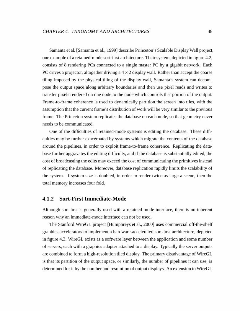
CHAPTER 4. TAXONOMY AND ARCHITECTURES 48
Samanta et al. [Samanta et al., 1999] describe Princeton’s Scalable Display Wall project,
one example of a retained-mode sort-first architecture. Their system, depicted in figure 4.2,
consists of 8 rendering PCs connected to a single master PC by a gigabit network. Each
PC drives a projector, altogether driving a 4×2 display wall. Rather than accept the coarse
tiling imposed by the physical tiling of the display wall, Samanta’s system can decom-
pose the output space along arbitrary boundaries and then use pixel reads and writes to
transfer pixels rendered on one node to the node which controls that portion of the output.
Frame-to-frame coherence is used to dynamically partition the screen into tiles, with the
assumption that the current frame’s distribution of work will be very similar to the previous
frame. The Princeton system replicates the database on each node, so that geometry never
needs to be communicated.
One of the difficulties of retained-mode systems is editing the database. These diffi-
culties may be further exacerbated by systems which migrate the contents of the database
around the pipelines, in order to exploit frame-to-frame coherence. Replicating the data-
base further aggravates the editing difficulty, and if the database is substantially edited, the
cost of broadcasting the edits may exceed the cost of communicating the primitives instead
of replicating the database. Moreover, database replication rapidly limits the scalability of
the system. If system size is doubled, in order to render twice as large a scene, then the
total memory increases four fold.
4.1.2 Sort-First Immediate-Mode
Although sort-first is generally used with a retained-mode interface, there is no inherent
reason why an immediate-mode interface can not be used.
The Stanford WireGL project [Humphreys et al., 2000] uses commercial off-the-shelf
graphics accelerators to implement a hardware-accelerated sort-first architecture, depicted
in figure 4.3. WireGL exists as a software layer between the application and some number
of servers, each with a graphics adapter attached to a display. Typically the server outputs
are combined to form a high-resolution tiled display. The primary disadvantage of WireGL
is that its partition of the output space, or similarly, the number of pipelines it can use, is
determined for it by the number and resolution of output displays. An extension to WireGL
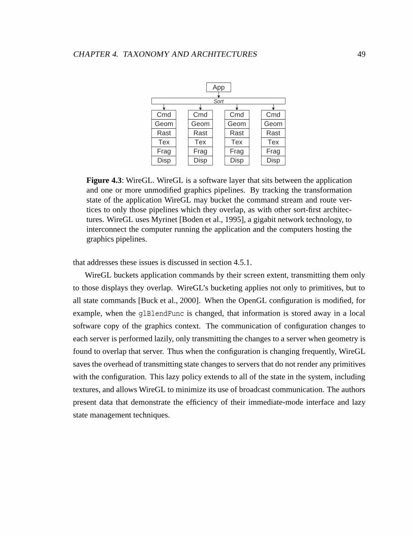
CHAPTER 4. TAXONOMY AND ARCHITECTURES 49
App
CmdGeomRastTexFragDisp
CmdGeomRastTexFragDisp
CmdGeomRastTexFragDisp
CmdGeomRastTexFragDisp
Sort
Figure 4.3: WireGL. WireGL is a software layer that sits between the applicationand one or more unmodified graphics pipelines. By tracking the transformationstate of the application WireGL may bucket the command stream and route ver-tices to only those pipelines which they overlap, as with other sort-first architec-tures. WireGL uses Myrinet [Boden et al., 1995], a gigabit network technology, tointerconnect the computer running the application and the computers hosting thegraphics pipelines.
that addresses these issues is discussed in section 4.5.1.
WireGL buckets application commands by their screen extent, transmitting them only
to those displays they overlap. WireGL’s bucketing applies not only to primitives, but to
all state commands [Buck et al., 2000]. When the OpenGL configuration is modified, for
example, when the glBlendFunc is changed, that information is stored away in a local
software copy of the graphics context. The communication of configuration changes to
each server is performed lazily, only transmitting the changes to a server when geometry is
found to overlap that server. Thus when the configuration is changing frequently, WireGL
saves the overhead of transmitting state changes to servers that do not render any primitives
with the configuration. This lazy policy extends to all of the state in the system, including
textures, and allows WireGL to minimize its use of broadcast communication. The authors
present data that demonstrate the efficiency of their immediate-mode interface and lazy
state management techniques.
CHAPTER 4. TAXONOMY AND ARCHITECTURES 50
4.2 Sort-Middle
Sort-middle is the most widely implemented and published parallel graphics architecture.
Sort-middle architectures can be separated into two distinct categories: interleaved and
tiled. Interleaved architectures use interleaved image parallelism, broadcasting each primi-
tive to all rasterizers. Tiled architectures use tiled image parallelism, routing each primitive
to only those rasterizers whose partition it overlaps.
4.2.1 Sort-Middle Interleaved
A representative example of a sort-middle interleaved architecture is SGI’s InfiniteReal-
ity [Montrym et al., 1997], depicted in figure 4.4. InfiniteReality interleaves the screen
across the rasterizers in 2-pixel wide vertical stripes, and broadcasts primitives to all the
rasterizers. Interestingly, the InfiniteReality only offers scalable rasterization performance
– the system always contains 4 geometry processors.1 Thus, the vertex bus and the rasteriz-
ers always need to handle 4 geometry processors, and adding more rasterizers only changes
the balance point between geometry and rasterization to correspondingly larger primitives.
The authors make a specific point that this interleaving of the rasterizers was chosen to
insure load-balanced drawing. However, as a consequence of this choice the vertex bus is
a broadcast mechanism, and thus the geometry performance of the system is unscalable –
additional geometry units would have no vertex bus bandwidth available.2
4.2.2 Sort-Middle Tiled
Unlike sort-middle interleaved architectures, sort-middle tiled architectures to not broad-
cast primitives between the geometry processors and rasterizers, and thus may scale to
higher levels of performance. Tiled architectures have been constructed in two broad
1InfiniteReality configurations with only 2 geometry processors were sold, and an 8 geometry processorconfiguration was demonstrated.
2The use of more complicated geometric processing (for example, more lights or more frequent clipping)or image processing operations (which are performed by InfiniteReality’s geometry processors) decreases thebandwidth to computation ratio of the geometry processors, and would allow more geometry processors tobe effectively utilized. However, the vertex bus bandwidth will still ultimately limit how many triangles persecond the system can process.
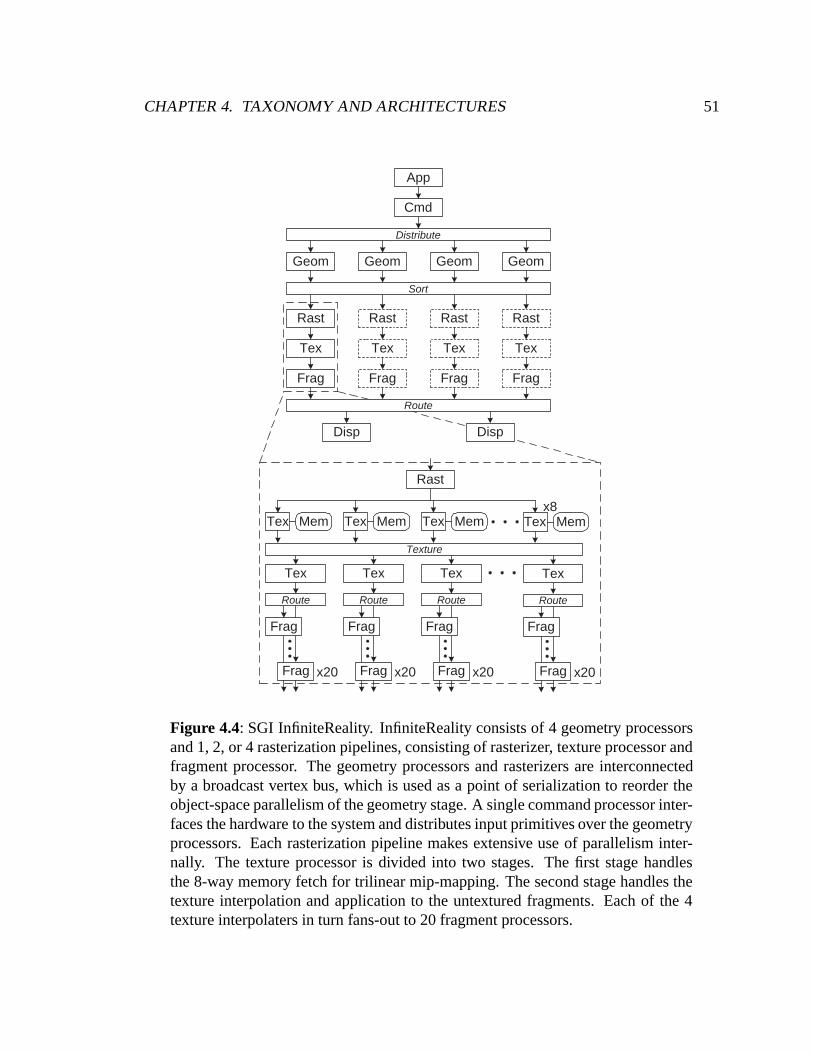
CHAPTER 4. TAXONOMY AND ARCHITECTURES 51
Cmd
Geom Geom GeomGeom
Rast
Tex
Frag
Rast
Tex
Frag
Rast
Tex
Frag
Rast
Tex
Frag
Route
Disp Disp
App
Rast
Tex Tex Tex TexMemMem Mem Memx8
Sort
Texture
Distribute
Frag
Tex
Frag x20
Route
Frag
Tex
Frag x20
Route
Frag
Tex
Frag x20
Route
Frag
Tex
Frag x20
Route
Figure 4.4: SGI InfiniteReality. InfiniteReality consists of 4 geometry processorsand 1, 2, or 4 rasterization pipelines, consisting of rasterizer, texture processor andfragment processor. The geometry processors and rasterizers are interconnectedby a broadcast vertex bus, which is used as a point of serialization to reorder theobject-space parallelism of the geometry stage. A single command processor inter-faces the hardware to the system and distributes input primitives over the geometryprocessors. Each rasterization pipeline makes extensive use of parallelism inter-nally. The texture processor is divided into two stages. The first stage handlesthe 8-way memory fetch for trilinear mip-mapping. The second stage handles thetexture interpolation and application to the untextured fragments. Each of the 4texture interpolaters in turn fans-out to 20 fragment processors.
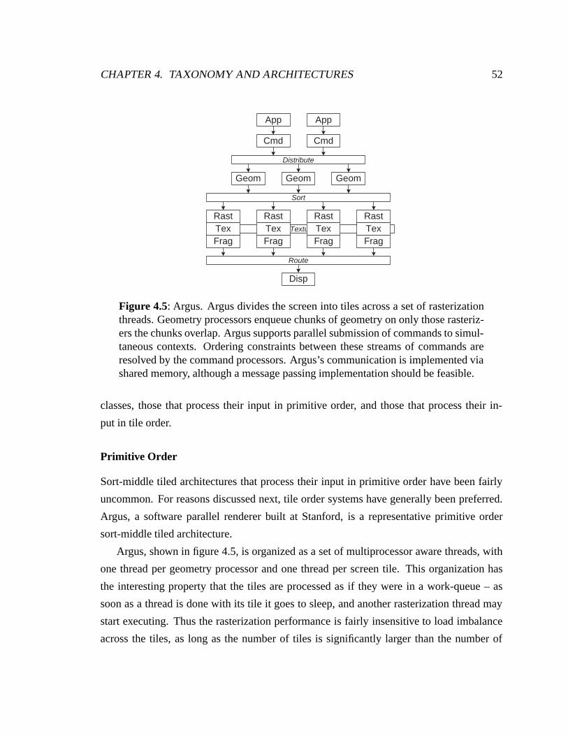
CHAPTER 4. TAXONOMY AND ARCHITECTURES 52
Texture
Cmd
GeomGeom
Disp
App
Cmd
App
Distribute
Sort
Geom
RastTexFrag
RastTexFrag
RastTexFrag
RastTexFrag
Route
Figure 4.5: Argus. Argus divides the screen into tiles across a set of rasterizationthreads. Geometry processors enqueue chunks of geometry on only those rasteriz-ers the chunks overlap. Argus supports parallel submission of commands to simul-taneous contexts. Ordering constraints between these streams of commands areresolved by the command processors. Argus’s communication is implemented viashared memory, although a message passing implementation should be feasible.
classes, those that process their input in primitive order, and those that process their in-
put in tile order.
Primitive Order
Sort-middle tiled architectures that process their input in primitive order have been fairly
uncommon. For reasons discussed next, tile order systems have generally been preferred.
Argus, a software parallel renderer built at Stanford, is a representative primitive order
sort-middle tiled architecture.
Argus, shown in figure 4.5, is organized as a set of multiprocessor aware threads, with
one thread per geometry processor and one thread per screen tile. This organization has
the interesting property that the tiles are processed as if they were in a work-queue – as
soon as a thread is done with its tile it goes to sleep, and another rasterization thread may
start executing. Thus the rasterization performance is fairly insensitive to load imbalance
across the tiles, as long as the number of tiles is significantly larger than the number of
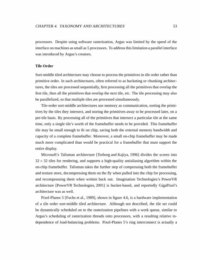
CHAPTER 4. TAXONOMY AND ARCHITECTURES 53
processors. Despite using software rasterization, Argus was limited by the speed of the
interface on machines as small as 5 processors. To address this limitation a parallel interface
was introduced by Argus’s creators.
Tile Order
Sort-middle tiled architecture may choose to process the primitives in tile order rather than
primitive order. In such architectures, often referred to as bucketing or chunking architec-
tures, the tiles are processed sequentially, first processing all the primitives that overlap the
first tile, then all the primitives that overlap the next tile, etc. The tile processing may also
be parallelized, so that multiple tiles are processed simultaneously.
Tile-order sort-middle architectures use memory as communication, sorting the primi-
tives by the tiles they intersect, and storing the primitives away to be processed later, on a
per-tile basis. By processing all of the primitives that intersect a particular tile at the same
time, only a single tile’s worth of the framebuffer needs to be provided. This framebuffer
tile may be small enough to fit on chip, saving both the external memory bandwidth and
capacity of a complete framebuffer. Moreover, a small on-chip framebuffer may be made
much more complicated than would be practical for a framebuffer that must support the
entire display.
Microsoft’s Talisman architecture [Torborg and Kajiya, 1996] divides the screen into
32× 32 tiles for rendering, and supports a high-quality antialiasing algorithm within the
on-chip framebuffer. Talisman takes the further step of compressing both the framebuffer
and texture store, decompressing them on the fly when pulled into the chip for processing,
and recompressing them when written back out. Imagination Technologies’s PowerVR
architecture [PowerVR Technologies, 2001] is bucket-based, and reportedly GigaPixel’s
architecture was as well.
Pixel-Planes 5 [Fuchs et al., 1989], shown in figure 4.6, is a hardware implementation
of a tile order sort-middle tiled architecture. Although not described, the tile set could
be dynamically scheduled on to the rasterization pipelines with a work queue, similar to
Argus’s scheduling of rasterization threads onto processors, with a resulting relative in-
dependence of load-balancing problems. Pixel-Planes 5’s ring interconnect is actually a
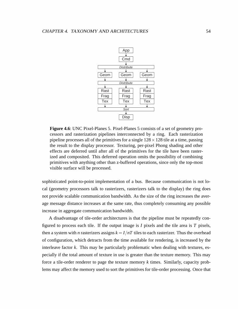
CHAPTER 4. TAXONOMY AND ARCHITECTURES 54
Disp
Geom Geom Geom
Distribute
App
Cmd
Distribute
Tex
RastFrag
Tex
RastFrag
Tex
RastFrag
Sort
Figure 4.6: UNC Pixel-Planes 5. Pixel-Planes 5 consists of a set of geometry pro-cessors and rasterization pipelines interconnected by a ring. Each rasterizationpipeline processes all of the primitives for a single 128×128 tile at a time, passingthe result to the display processor. Texturing, per-pixel Phong shading and othereffects are deferred until after all of the primitives for the tile have been raster-ized and composited. This deferred operation omits the possibility of combiningprimitives with anything other than z-buffered operations, since only the top-mostvisible surface will be processed.
sophisticated point-to-point implementation of a bus. Because communication is not lo-
cal (geometry processors talk to rasterizers, rasterizers talk to the display) the ring does
not provide scalable communication bandwidth. As the size of the ring increases the aver-
age message distance increases at the same rate, thus completely consuming any possible
increase in aggregate communication bandwidth.
A disadvantage of tile-order architectures is that the pipeline must be repeatedly con-
figured to process each tile. If the output image is I pixels and the tile area is T pixels,
then a system with n rasterizers assigns k = I/nT tiles to each rasterizer. Thus the overhead
of configuration, which detracts from the time available for rendering, is increased by the
interleave factor k. This may be particularly problematic when dealing with textures, es-
pecially if the total amount of texture in use is greater than the texture memory. This may
force a tile-order renderer to page the texture memory k times. Similarly, capacity prob-
lems may affect the memory used to sort the primitives for tile-order processing. Once that
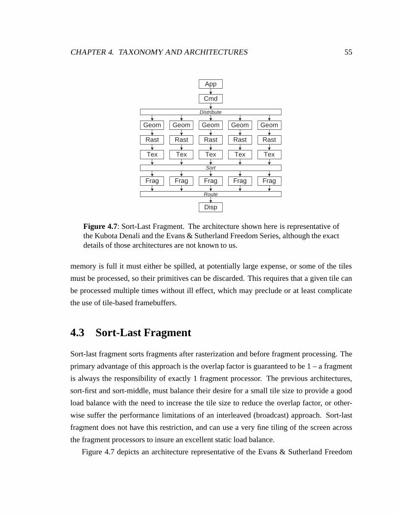
CHAPTER 4. TAXONOMY AND ARCHITECTURES 55
Cmd
App
Geom
Rast
Tex
Geom
Rast
Tex
Geom
Rast
Tex
Geom
Rast
Tex
Geom
Rast
Tex
Disp
Distribute
Frag Frag Frag Frag Frag
Sort
Route
Figure 4.7: Sort-Last Fragment. The architecture shown here is representative ofthe Kubota Denali and the Evans & Sutherland Freedom Series, although the exactdetails of those architectures are not known to us.
memory is full it must either be spilled, at potentially large expense, or some of the tiles
must be processed, so their primitives can be discarded. This requires that a given tile can
be processed multiple times without ill effect, which may preclude or at least complicate
the use of tile-based framebuffers.
4.3 Sort-Last Fragment
Sort-last fragment sorts fragments after rasterization and before fragment processing. The
primary advantage of this approach is the overlap factor is guaranteed to be 1 – a fragment
is always the responsibility of exactly 1 fragment processor. The previous architectures,
sort-first and sort-middle, must balance their desire for a small tile size to provide a good
load balance with the need to increase the tile size to reduce the overlap factor, or other-
wise suffer the performance limitations of an interleaved (broadcast) approach. Sort-last
fragment does not have this restriction, and can use a very fine tiling of the screen across
the fragment processors to insure an excellent static load balance.
Figure 4.7 depicts an architecture representative of the Evans & Sutherland Freedom
CHAPTER 4. TAXONOMY AND ARCHITECTURES 56
Series [Evans & Sutherland, 1992] and the Kubota Denali [Kubota Pacific, 1993], two sort-
last fragment architectures. Although not discussed, both of these architectures likely suffer
the Achilles heel of conventional sort-last fragment architectures: geometry processing
and rasterization are coupled together. The result is that there is no control over the load
balance of rasterization work; if a geometry processor happens to get a large primitive, or a
succession of large primitives, they will all be handled by its associated rasterizer. At best
this can push the pipelines out of balance, limiting the potential speedup of the hardware.
At worst, if the primitives are committed to the framebuffer in order the hardware can
become serialized – not only reducing speedup due to load imbalance, but the heavily
loaded rasterizer will block other rasterizers from making forward progress.
4.4 Sort-Last Image Composition
Sort-last image composition architectures composite multiple depth-buffered images, the
final result of a conventional graphics pipeline, to form their final output. Image compo-
sition architectures have no control over the order of framebuffer operations because each
pipeline renders its subset of the primitives into its own framebuffer, which may overlap
the primitives of other pipelines. As such, they forego support for ordered semantics, and
represent a significant departure from the previous architectures. Image composition ar-
chitectures can suffer from the same load-balancing problems seen in sort-last fragment
architectures – the different rasterization processors of each pipeline may have differing
amounts of work to do. The load imbalance here is extended to the fragment processors,
but assuming their performance is matched to the rasterizers, the performance impact is the
same as for sort-last fragment.
Sort-last image composition architectures have the unusual property of requiring a fixed
communication bandwidth, dependent on the size of the output. All of the previous archi-
tectures require a variable amount of communication, proportional to the size of the input.
This fixed communication pattern is often cited as a large advantage of sort-last image
composition architectures, but it comes at a high initial price. Compositing a 1280×1024
display at 60Hz with depth compositing requires 450 Mbyte/sec of communication, assum-
ing 24-bit color and 24-bit depth. If we increase the resolution to 1920×1200 at 72Hz, the
CHAPTER 4. TAXONOMY AND ARCHITECTURES 57
bandwidth increases to 950 Mbyte/sec. While this is a very manageable amount of com-
munication, particularly when we consider that modern memory interfaces operate at 1 to
2 Gbyte/sec, multisample antialiasing could increase this bandwidth by a factor of 4 to 8,
which starts to get significant.
The communication for image compositing may be broadly classified as either pipelined,
with each graphics pipeline compositing its local framebuffer with that of its upstream
neighbor, or non-pipelined.
4.4.1 Pipelined Image Composition
The promise of pipelined image composition architectures has been their ability to provide
linear scalability by connecting the graphics pipelines in a chain. Each graphics pipeline
composites its local framebuffer with the stream of framebuffer data arriving from its up-
stream neighbor, passing the composited result to its downstream neighbor. The composit-
ing may be fully pipelined, so the total delay from the completion of the frame (at which
point the output may be start to be composited) to a complete output image need only be
the raw time to composite one pipeline’s framebuffer with its neighbor, plus the negligible
latency of the pipeline-to-pipeline communication times the number of pipelines. If this
composition is done at video rates, then the final stage of the image composition pipeline
can directly drive the display, with the result that the compositing operation introduces
almost no latency.
PixelFlow [Molnar et al., 1992, Eyles et al., 1997], shown in figure 4.8, is one hard-
ware implementation of a pipelined image composition architecture. PixelFlow supports
multiple simultaneous interfaces into the hardware, providing the possibility of a parallel
interface and application. An additional ring interconnect allows for the distribution of
commands over geometry processors, however, as with sort-last fragment, such a distribu-
tion can readily fall victim to large primitive effects. This effect is mitigated in PixelFlow
by its SIMD rasterization architecture. By processing 32× 32 pixels simultaneously3 the
effective primitive area becomes 1024 times smaller. PixelFlow defers potentially expen-
sive texture operations, as well as its more general programming shading operations, until
364× 128 samples are processed simultaneously, with a resulting pixel stamp of 32× 32 pixels whenusing 8-way supersampling.
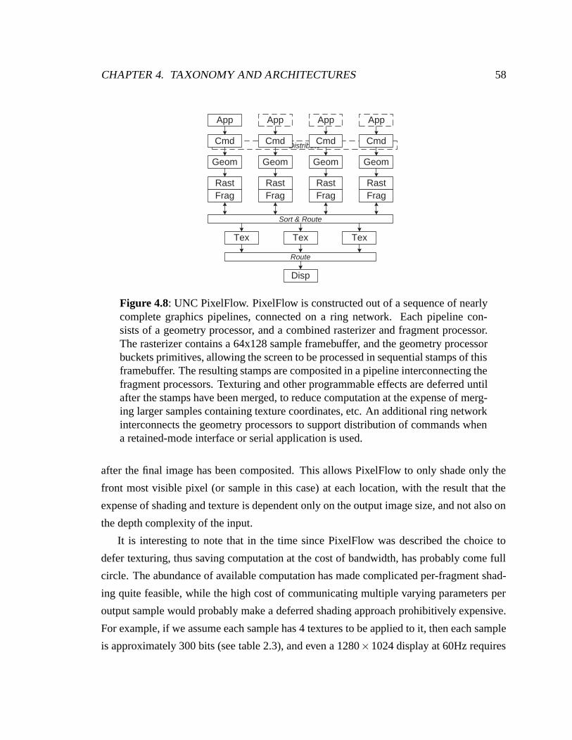
CHAPTER 4. TAXONOMY AND ARCHITECTURES 58
Distribute
App App AppApp
Disp
Cmd
Geom
RastFrag
Cmd
Geom
RastFrag
Cmd
Geom
RastFrag
Cmd
Geom
RastFrag
Sort & Route
Tex Tex Tex
Route
Figure 4.8: UNC PixelFlow. PixelFlow is constructed out of a sequence of nearlycomplete graphics pipelines, connected on a ring network. Each pipeline con-sists of a geometry processor, and a combined rasterizer and fragment processor.The rasterizer contains a 64x128 sample framebuffer, and the geometry processorbuckets primitives, allowing the screen to be processed in sequential stamps of thisframebuffer. The resulting stamps are composited in a pipeline interconnecting thefragment processors. Texturing and other programmable effects are deferred untilafter the stamps have been merged, to reduce computation at the expense of merg-ing larger samples containing texture coordinates, etc. An additional ring networkinterconnects the geometry processors to support distribution of commands whena retained-mode interface or serial application is used.
after the final image has been composited. This allows PixelFlow to only shade only the
front most visible pixel (or sample in this case) at each location, with the result that the
expense of shading and texture is dependent only on the output image size, and not also on
the depth complexity of the input.
It is interesting to note that in the time since PixelFlow was described the choice to
defer texturing, thus saving computation at the cost of bandwidth, has probably come full
circle. The abundance of available computation has made complicated per-fragment shad-
ing quite feasible, while the high cost of communicating multiple varying parameters per
output sample would probably make a deferred shading approach prohibitively expensive.
For example, if we assume each sample has 4 textures to be applied to it, then each sample
is approximately 300 bits (see table 2.3), and even a 1280×1024 display at 60Hz requires
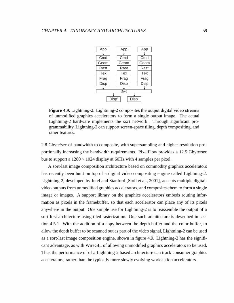
CHAPTER 4. TAXONOMY AND ARCHITECTURES 59
Frag
App
CmdGeomRastTex
DispFrag
App
CmdGeomRastTex
DispFrag
App
CmdGeomRastTex
Disp
Sort
Disp' Disp'
Figure 4.9: Lightning-2. Lightning-2 composites the output digital video streamsof unmodified graphics accelerators to form a single output image. The actualLightning-2 hardware implements the sort network. Through significant pro-grammability, Lightning-2 can support screen-space tiling, depth compositing, andother features.
2.8 Gbyte/sec of bandwidth to composite, with supersampling and higher resolution pro-
portionally increasing the bandwidth requirements. PixelFlow provides a 12.5 Gbyte/sec
bus to support a 1280×1024 display at 60Hz with 4 samples per pixel.
A sort-last image composition architecture based on commodity graphics accelerators
has recently been built on top of a digital video compositing engine called Lightning-2.
Lightning-2, developed by Intel and Stanford [Stoll et al., 2001], accepts multiple digital-
video outputs from unmodified graphics accelerators, and composites them to form a single
image or images. A support library on the graphics accelerators embeds routing infor-
mation as pixels in the framebuffer, so that each accelerator can place any of its pixels
anywhere in the output. One simple use for Lightning-2 is to reassemble the output of a
sort-first architecture using tiled rasterization. One such architecture is described in sec-
tion 4.5.1. With the addition of a copy between the depth buffer and the color buffer, to
allow the depth buffer to be scanned out as part of the video signal, Lightning-2 can be used
as a sort-last image composition engine, shown in figure 4.9. Lightning-2 has the signifi-
cant advantage, as with WireGL, of allowing unmodified graphics accelerators to be used.
Thus the performance of of a Lightning-2 based architecture can track consumer graphics
accelerators, rather than the typically more slowly evolving workstation accelerators.
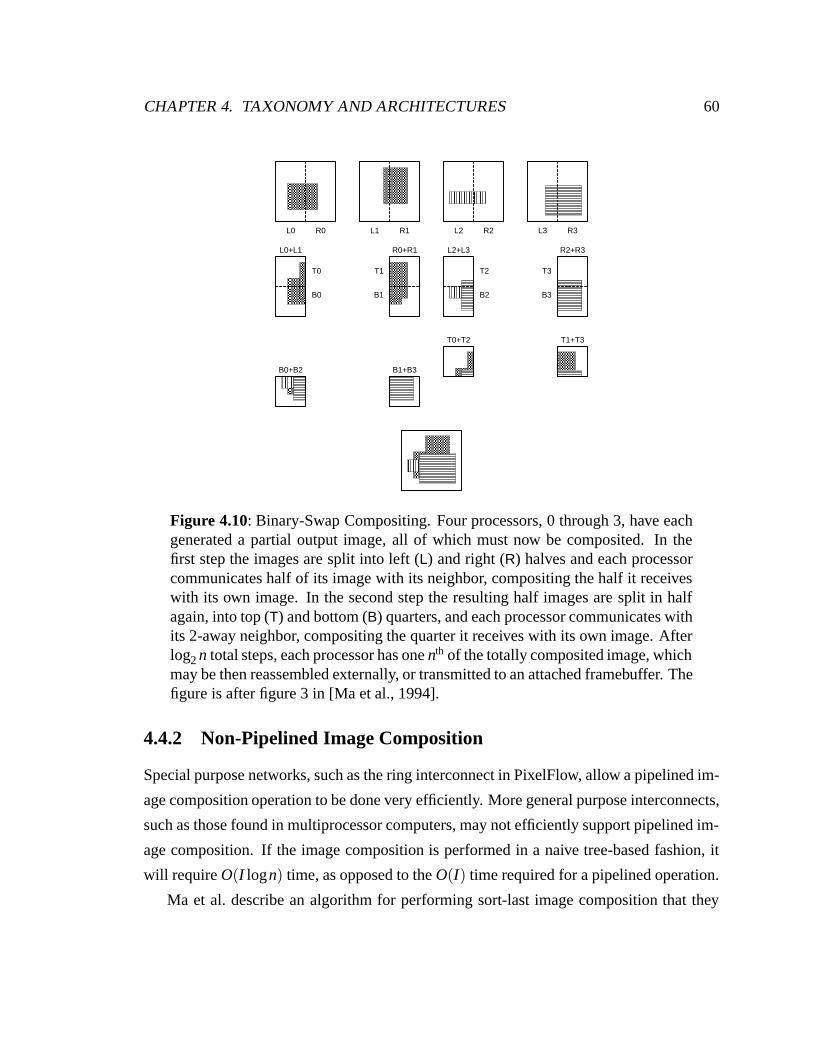
CHAPTER 4. TAXONOMY AND ARCHITECTURES 60
L0 R0 L1 R1 L2 R2 L3 R3
T0
B0
T1
B1
T2
B2
T3
B3
L0+L1 R0+R1 L2+L3 R2+R3
B0+B2 B1+B3
T0+T2 T1+T3
Figure 4.10: Binary-Swap Compositing. Four processors, 0 through 3, have eachgenerated a partial output image, all of which must now be composited. In thefirst step the images are split into left (L) and right (R) halves and each processorcommunicates half of its image with its neighbor, compositing the half it receiveswith its own image. In the second step the resulting half images are split in halfagain, into top (T) and bottom (B) quarters, and each processor communicates withits 2-away neighbor, compositing the quarter it receives with its own image. Afterlog2 n total steps, each processor has one nth of the totally composited image, whichmay be then reassembled externally, or transmitted to an attached framebuffer. Thefigure is after figure 3 in [Ma et al., 1994].
4.4.2 Non-Pipelined Image Composition
Special purpose networks, such as the ring interconnect in PixelFlow, allow a pipelined im-
age composition operation to be done very efficiently. More general purpose interconnects,
such as those found in multiprocessor computers, may not efficiently support pipelined im-
age composition. If the image composition is performed in a naive tree-based fashion, it
will require O(I logn) time, as opposed to the O(I) time required for a pipelined operation.
Ma et al. describe an algorithm for performing sort-last image composition that they
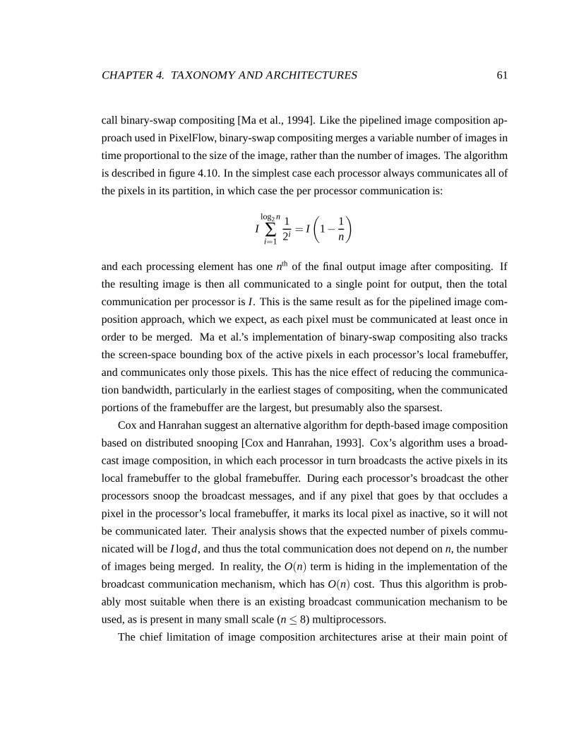
CHAPTER 4. TAXONOMY AND ARCHITECTURES 61
call binary-swap compositing [Ma et al., 1994]. Like the pipelined image composition ap-
proach used in PixelFlow, binary-swap compositing merges a variable number of images in
time proportional to the size of the image, rather than the number of images. The algorithm
is described in figure 4.10. In the simplest case each processor always communicates all of
the pixels in its partition, in which case the per processor communication is:
Ilog2 n
∑i=1
12i = I
(1− 1
n
)
and each processing element has one nth of the final output image after compositing. If
the resulting image is then all communicated to a single point for output, then the total
communication per processor is I. This is the same result as for the pipelined image com-
position approach, which we expect, as each pixel must be communicated at least once in
order to be merged. Ma et al.’s implementation of binary-swap compositing also tracks
the screen-space bounding box of the active pixels in each processor’s local framebuffer,
and communicates only those pixels. This has the nice effect of reducing the communica-
tion bandwidth, particularly in the earliest stages of compositing, when the communicated
portions of the framebuffer are the largest, but presumably also the sparsest.
Cox and Hanrahan suggest an alternative algorithm for depth-based image composition
based on distributed snooping [Cox and Hanrahan, 1993]. Cox’s algorithm uses a broad-
cast image composition, in which each processor in turn broadcasts the active pixels in its
local framebuffer to the global framebuffer. During each processor’s broadcast the other
processors snoop the broadcast messages, and if any pixel that goes by that occludes a
pixel in the processor’s local framebuffer, it marks its local pixel as inactive, so it will not
be communicated later. Their analysis shows that the expected number of pixels commu-
nicated will be I logd, and thus the total communication does not depend on n, the number
of images being merged. In reality, the O(n) term is hiding in the implementation of the
broadcast communication mechanism, which has O(n) cost. Thus this algorithm is prob-
ably most suitable when there is an existing broadcast communication mechanism to be
used, as is present in many small scale (n ≤ 8) multiprocessors.
The chief limitation of image composition architectures arise at their main point of
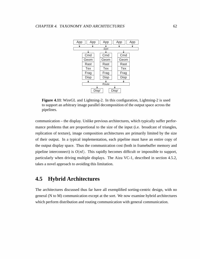
CHAPTER 4. TAXONOMY AND ARCHITECTURES 62
Disp' Disp'
App App App App App
Tex
CmdGeomRast
FragDisp
Tex
CmdGeomRast
FragDisp
Tex
CmdGeomRast
FragDisp
Sort
Route
Figure 4.11: WireGL and Lightning-2. In this configuration, Lightning-2 is usedto support an arbitrary image parallel decomposition of the output space across thepipelines.
communication – the display. Unlike previous architectures, which typically suffer perfor-
mance problems that are proportional to the size of the input (i.e. broadcast of triangles,
replication of texture), image composition architectures are primarily limited by the size
of their output. In a typical implementation, each pipeline must have an entire copy of
the output display space. Thus the communication cost (both in framebuffer memory and
pipeline interconnect) is O(nI). This rapidly becomes difficult or impossible to support,
particularly when driving multiple displays. The Aizu VC-1, described in section 4.5.2,
takes a novel approach to avoiding this limitation.
4.5 Hybrid Architectures
The architectures discussed thus far have all exemplified sorting-centric design, with no
general (N to M) communication except at the sort. We now examine hybrid architectures
which perform distribution and routing communication with general communication.
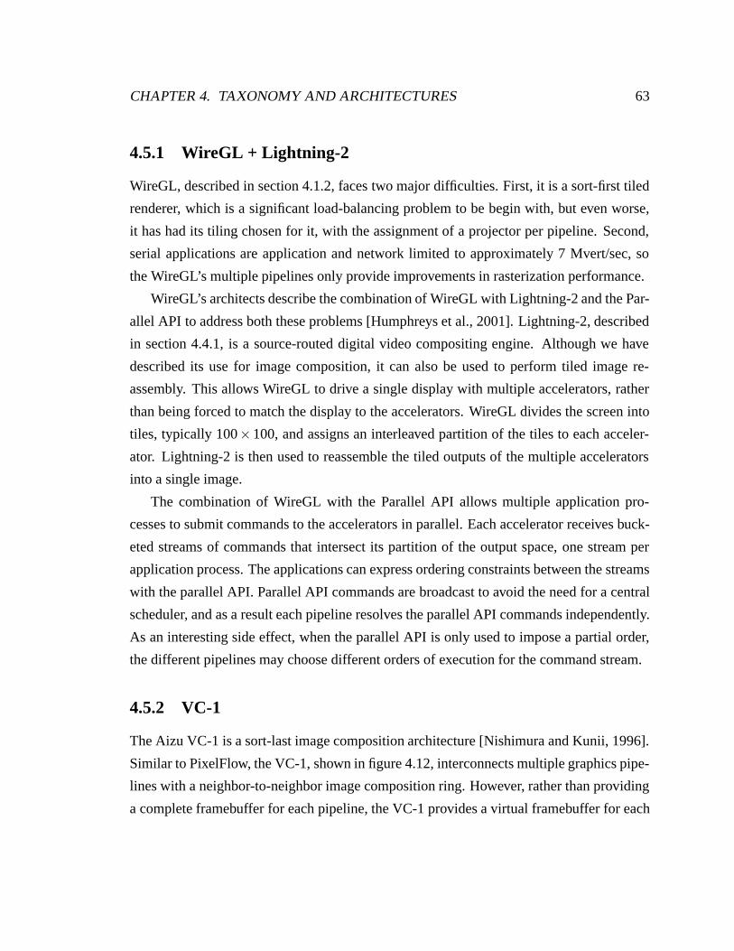
CHAPTER 4. TAXONOMY AND ARCHITECTURES 63
4.5.1 WireGL + Lightning-2
WireGL, described in section 4.1.2, faces two major difficulties. First, it is a sort-first tiled
renderer, which is a significant load-balancing problem to be begin with, but even worse,
it has had its tiling chosen for it, with the assignment of a projector per pipeline. Second,
serial applications are application and network limited to approximately 7 Mvert/sec, so
the WireGL’s multiple pipelines only provide improvements in rasterization performance.
WireGL’s architects describe the combination of WireGL with Lightning-2 and the Par-
allel API to address both these problems [Humphreys et al., 2001]. Lightning-2, described
in section 4.4.1, is a source-routed digital video compositing engine. Although we have
described its use for image composition, it can also be used to perform tiled image re-
assembly. This allows WireGL to drive a single display with multiple accelerators, rather
than being forced to match the display to the accelerators. WireGL divides the screen into
tiles, typically 100×100, and assigns an interleaved partition of the tiles to each acceler-
ator. Lightning-2 is then used to reassemble the tiled outputs of the multiple accelerators
into a single image.
The combination of WireGL with the Parallel API allows multiple application pro-
cesses to submit commands to the accelerators in parallel. Each accelerator receives buck-
eted streams of commands that intersect its partition of the output space, one stream per
application process. The applications can express ordering constraints between the streams
with the parallel API. Parallel API commands are broadcast to avoid the need for a central
scheduler, and as a result each pipeline resolves the parallel API commands independently.
As an interesting side effect, when the parallel API is only used to impose a partial order,
the different pipelines may choose different orders of execution for the command stream.
4.5.2 VC-1
The Aizu VC-1 is a sort-last image composition architecture [Nishimura and Kunii, 1996].
Similar to PixelFlow, the VC-1, shown in figure 4.12, interconnects multiple graphics pipe-
lines with a neighbor-to-neighbor image composition ring. However, rather than providing
a complete framebuffer for each pipeline, the VC-1 provides a virtual framebuffer for each
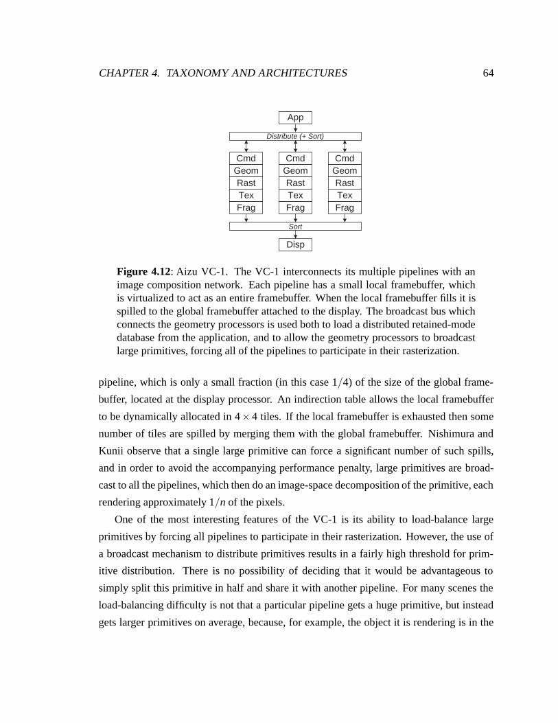
CHAPTER 4. TAXONOMY AND ARCHITECTURES 64
Tex
App
CmdGeomRast
Frag
Disp
Tex
CmdGeomRast
FragTex
CmdGeomRast
Frag
Distribute (+ Sort)
Sort
Figure 4.12: Aizu VC-1. The VC-1 interconnects its multiple pipelines with animage composition network. Each pipeline has a small local framebuffer, whichis virtualized to act as an entire framebuffer. When the local framebuffer fills it isspilled to the global framebuffer attached to the display. The broadcast bus whichconnects the geometry processors is used both to load a distributed retained-modedatabase from the application, and to allow the geometry processors to broadcastlarge primitives, forcing all of the pipelines to participate in their rasterization.
pipeline, which is only a small fraction (in this case 1/4) of the size of the global frame-
buffer, located at the display processor. An indirection table allows the local framebuffer
to be dynamically allocated in 4×4 tiles. If the local framebuffer is exhausted then some
number of tiles are spilled by merging them with the global framebuffer. Nishimura and
Kunii observe that a single large primitive can force a significant number of such spills,
and in order to avoid the accompanying performance penalty, large primitives are broad-
cast to all the pipelines, which then do an image-space decomposition of the primitive, each
rendering approximately 1/n of the pixels.
One of the most interesting features of the VC-1 is its ability to load-balance large
primitives by forcing all pipelines to participate in their rasterization. However, the use of
a broadcast mechanism to distribute primitives results in a fairly high threshold for prim-
itive distribution. There is no possibility of deciding that it would be advantageous to
simply split this primitive in half and share it with another pipeline. For many scenes the
load-balancing difficulty is not that a particular pipeline gets a huge primitive, but instead
gets larger primitives on average, because, for example, the object it is rendering is in the
CHAPTER 4. TAXONOMY AND ARCHITECTURES 65
foreground.
The VC-1’s virtualization of the local framebuffer presents the possibility of address-
ing one of the main disadvantages of the sort-last image composition architectures. In a
conventional sort-last image composition architecture, each pipeline has a complete frame-
buffer at full output resolution; consequently, increasing the output resolution has a cost
linear in both the output size and the number of pipelines. The VC-1 can, within limits,
keep the per-pipeline framebuffer size constant while varying the output framebuffer size.
4.6 Observations
We summarize the architectures we have discussed, as well as additional graphics archi-
tectures, in table 4.6. We draw a number of observations from these architectures. First,
the performance of the hardware is often interface limited. Second, the performance of the
system can depend on factors not readily visible to the programmer, such as the screen-
space area of primitives. Additionally, the texture subsystem is quickly becoming the most
demanding point of communication in the graphics pipeline, both in bandwidth and mem-
ory capacity. Finally, temporal locality in the input can result in spatial load imbalances for
image parallelism. We will discuss these observed difficulties, and discuss some ways of
addressing them.
4.6.1 Interface Limit
Modern graphics hardware can process immediate-mode input commands at a rate greater
than they can be generated by an application specifically tuned to do nothing but com-
mand submission. The fact that most applications do more work than simply driving the
graphics pipeline, sometimes significantly more, only worsens the situation. The result is
that the hardware’s performance is application-limited in many situations. The problem is
not that the interconnect between the processor and the hardware is not fast enough, al-
though that can be an issue, but that the application simply can not generate commands
fast enough to keep the hardware busy. We refer to this common problem as interface
limited performance, where the limitation is due to one or more of the application, the
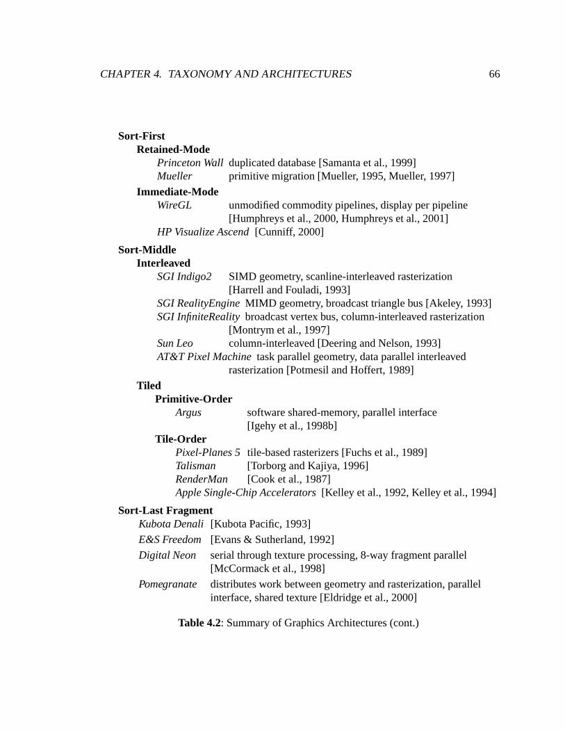
CHAPTER 4. TAXONOMY AND ARCHITECTURES 66
Sort-FirstRetained-Mode
Princeton Wall duplicated database [Samanta et al., 1999]Mueller primitive migration [Mueller, 1995, Mueller, 1997]
Immediate-ModeWireGL unmodified commodity pipelines, display per pipeline
[Humphreys et al., 2000, Humphreys et al., 2001]HP Visualize Ascend [Cunniff, 2000]
Sort-MiddleInterleaved
SGI Indigo2 SIMD geometry, scanline-interleaved rasterization[Harrell and Fouladi, 1993]
SGI RealityEngine MIMD geometry, broadcast triangle bus [Akeley, 1993]SGI InfiniteReality broadcast vertex bus, column-interleaved rasterization
[Montrym et al., 1997]Sun Leo column-interleaved [Deering and Nelson, 1993]AT&T Pixel Machine task parallel geometry, data parallel interleaved
rasterization [Potmesil and Hoffert, 1989]
TiledPrimitive-Order
Argus software shared-memory, parallel interface[Igehy et al., 1998b]
Tile-OrderPixel-Planes 5 tile-based rasterizers [Fuchs et al., 1989]Talisman [Torborg and Kajiya, 1996]RenderMan [Cook et al., 1987]Apple Single-Chip Accelerators [Kelley et al., 1992, Kelley et al., 1994]
Sort-Last FragmentKubota Denali [Kubota Pacific, 1993]
E&S Freedom [Evans & Sutherland, 1992]
Digital Neon serial through texture processing, 8-way fragment parallel[McCormack et al., 1998]
Pomegranate distributes work between geometry and rasterization, parallelinterface, shared texture [Eldridge et al., 2000]
Table 4.2: Summary of Graphics Architectures (cont.)
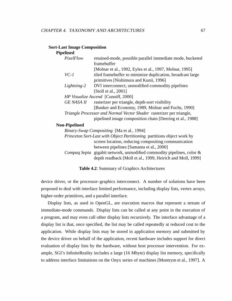
CHAPTER 4. TAXONOMY AND ARCHITECTURES 67
Sort-Last Image CompositionPipelined
PixelFlow retained-mode, possible parallel immediate mode, bucketedframebuffer[Molnar et al., 1992, Eyles et al., 1997, Molnar, 1995]
VC-1 tiled framebuffer to minimize duplication, broadcast largeprimitives [Nishimura and Kunii, 1996]
Lightning-2 DVI interconnect, unmodified commodity pipelines[Stoll et al., 2001]
HP Visualize Ascend [Cunniff, 2000]GE NASA II rasterizer per triangle, depth-sort visibility
[Bunker and Economy, 1989, Molnar and Fuchs, 1990]Triangle Processor and Normal Vector Shader rasterizer per triangle,
pipelined image composition chain [Deering et al., 1988]
Non-PipelinedBinary-Swap Compositing [Ma et al., 1994]Princeton Sort-Last with Object Partitioning partitions object work by
screen location, reducing compositing communicationbetween pipelines [Samanta et al., 2000]
Compaq Sepia gigabit network, unmodified commodity pipelines, color &depth readback [Moll et al., 1999, Heirich and Moll, 1999]
Table 4.2: Summary of Graphics Architectures
device driver, or the processor–graphics interconnect. A number of solutions have been
proposed to deal with interface limited performance, including display lists, vertex arrays,
higher-order primitives, and a parallel interface.
Display lists, as used in OpenGL, are execution macros that represent a stream of
immediate-mode commands. Display lists can be called at any point in the execution of
a program, and may even call other display lists recursively. The interface advantage of a
display list is that, once specified, the list may be called repeatedly at reduced cost to the
application. While display lists may be stored in application memory and submitted by
the device driver on behalf of the application, recent hardware includes support for direct
evaluation of display lists by the hardware, without host processor intervention. For ex-
ample, SGI’s InfiniteReality includes a large (16 Mbyte) display list memory, specifically
to address interface limitations on the Onyx series of machines [Montrym et al., 1997]. A
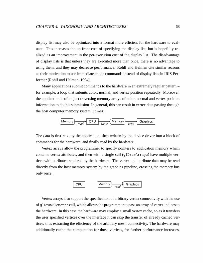
CHAPTER 4. TAXONOMY AND ARCHITECTURES 68
display list may also be optimized into a format more efficient for the hardware to eval-
uate. This increases the up-front cost of specifying the display list, but is hopefully re-
alized as an improvement in the per-execution cost of the display list. The disadvantage
of display lists is that unless they are executed more than once, there is no advantage to
using them, and they may decrease performance. Rohlf and Helman cite similar reasons
as their motivation to use immediate-mode commands instead of display lists in IRIS Per-
former [Rohlf and Helman, 1994].
Many applications submit commands to the hardware in an extremely regular pattern –
for example, a loop that submits color, normal, and vertex position repeatedly. Moreover,
the application is often just traversing memory arrays of color, normal and vertex position
information to do this submission. In general, this can result in vertex data passing through
the host computer memory system 3 times:
Memory CPU Memory Graphicsread write read
The data is first read by the application, then written by the device driver into a block of
commands for the hardware, and finally read by the hardware.
Vertex arrays allow the programmer to specify pointers to application memory which
contains vertex attributes, and then with a single call (glDrawArrays) have multiple ver-
tices with attributes rendered by the hardware. The vertex and attribute data may be read
directly from the host memory system by the graphics pipeline, crossing the memory bus
only once.
CPU Memory Graphicsread
Vertex arrays also support the specification of arbitrary vertex connectivity with the use
of glDrawElements call, which allows the programmer to pass an array of vertex indices to
the hardware. In this case the hardware may employ a small vertex cache, so as it transfers
the user specified vertices over the interface it can skip the transfer of already cached ver-
tices, thus extracting the efficiency of the arbitrary mesh connectivity. The hardware may
additionally cache the computation for those vertices, for further performance increases.
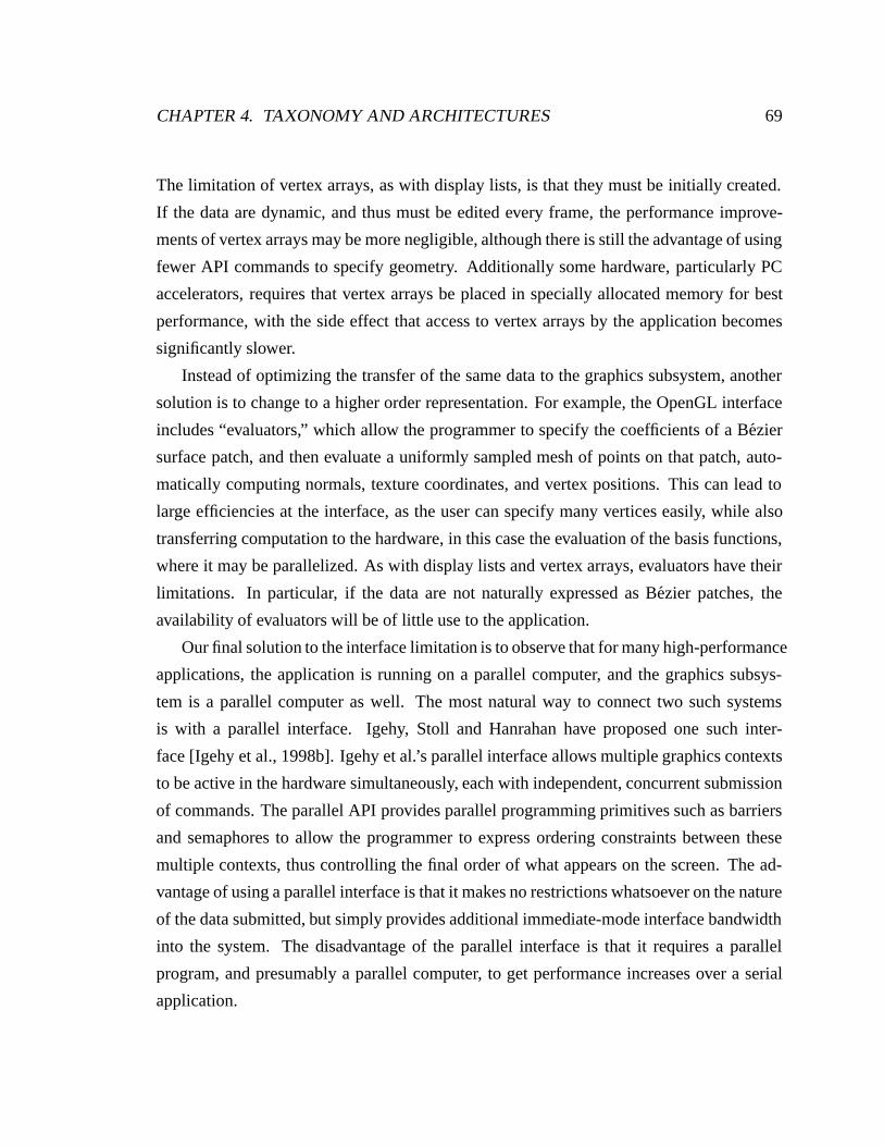
CHAPTER 4. TAXONOMY AND ARCHITECTURES 69
The limitation of vertex arrays, as with display lists, is that they must be initially created.
If the data are dynamic, and thus must be edited every frame, the performance improve-
ments of vertex arrays may be more negligible, although there is still the advantage of using
fewer API commands to specify geometry. Additionally some hardware, particularly PC
accelerators, requires that vertex arrays be placed in specially allocated memory for best
performance, with the side effect that access to vertex arrays by the application becomes
significantly slower.
Instead of optimizing the transfer of the same data to the graphics subsystem, another
solution is to change to a higher order representation. For example, the OpenGL interface
includes “evaluators,” which allow the programmer to specify the coefficients of a Bezier
surface patch, and then evaluate a uniformly sampled mesh of points on that patch, auto-
matically computing normals, texture coordinates, and vertex positions. This can lead to
large efficiencies at the interface, as the user can specify many vertices easily, while also
transferring computation to the hardware, in this case the evaluation of the basis functions,
where it may be parallelized. As with display lists and vertex arrays, evaluators have their
limitations. In particular, if the data are not naturally expressed as Bezier patches, the
availability of evaluators will be of little use to the application.
Our final solution to the interface limitation is to observe that for many high-performance
applications, the application is running on a parallel computer, and the graphics subsys-
tem is a parallel computer as well. The most natural way to connect two such systems
is with a parallel interface. Igehy, Stoll and Hanrahan have proposed one such inter-
face [Igehy et al., 1998b]. Igehy et al.’s parallel interface allows multiple graphics contexts
to be active in the hardware simultaneously, each with independent, concurrent submission
of commands. The parallel API provides parallel programming primitives such as barriers
and semaphores to allow the programmer to express ordering constraints between these
multiple contexts, thus controlling the final order of what appears on the screen. The ad-
vantage of using a parallel interface is that it makes no restrictions whatsoever on the nature
of the data submitted, but simply provides additional immediate-mode interface bandwidth
into the system. The disadvantage of the parallel interface is that it requires a parallel
program, and presumably a parallel computer, to get performance increases over a serial
application.
CHAPTER 4. TAXONOMY AND ARCHITECTURES 70
4.6.2 Application Visibility of Work
Ideally the graphics hardware has perfectly predictable performance. The application pro-
grammer could, for example, simply count the number of submitted vertices, divide by the
vertex rate of the hardware, and determine how long the scene will take to render. While
this will work for some applications, in general it is a poor model for the actual system
performance. Many factors break this model, two perhaps most significantly. First, overall
performance is often fill-limited. Thus the performance will depend on information, the
screen-space area of the primitives, which is not readily available to the programmer. Sec-
ond, new interfaces may adaptively tessellate geometry based on its screen-space projec-
tion. Thus the geometry performance may not even be readily predicted by the application.
If we are interested in a parallel interface to the hardware, because it can provide us
with greater immediate-mode command bandwidth, then we must be concerned with load-
balancing the multiple input command streams across the parallelism internal to the graph-
ics system. Most current applications submit simple primitives (triangles, quadrilaterals,
etc.) to the hardware, with the result that the geometry work is proportional to the num-
ber of vertices. As a consequence, the programmer is readily aware of how much geometry
work is being done per frame, because the submission of vertices is under programmer con-
trol. Thus parallel applications, which already must balance their input bandwidth across
the interfaces, naturally balance their geometric work across the interfaces.
Unlike geometric work, estimating a primitive’s rasterization work requires significant
programmer effort and potential run-time expense. As a consequence, architectures which
do not decouple their inputs from rasterization can have large resulting load imbalances.
For example, if a parallel application were to divide responsibility for command submission
by objects in the scene, then interfaces receiving objects close to the viewpoint will be
receiving a proportionally greater share of the rasterization work. Thus it is important to
decouple input parallelism from rasterization parallelism.
CHAPTER 4. TAXONOMY AND ARCHITECTURES 71
4.6.3 Texturing
With the extension of the graphics pipeline to include multiple textures per fragment, access
to texture memory is rapidly becoming the highest bandwidth point in graphics architec-
ture. In its most straightforward implementation, a mip-mapped texture access requires 8
memory reads to fetch 4-texel neighborhoods in each of two mip-map levels. Assuming
4-byte color, the texture memory bandwidth is 8×4 bytes per pixel, or 12.8 Gbyte/sec as-
suming a 400 Mpixel/sec fill rate. This bandwidth demand can be greatly reduced by using
texture caches, which can reduce texel reads by a factor of 4 or more.
For texture caches to work effectively, the texture processor must have good locality of
reference – the texels required to texture one fragment must be likely to be reused on sub-
sequent fragments. Igehy et al. analyzed the efficiency of texture caching under a variety
of rasterization schemes, and concluded that either object-parallel rasterization or tiled ras-
terization provide good texture cache efficiency, while interleaved rasterization has quite
poor texture cache efficiency [Igehy et al., 1999]. Their work assumed that rasterization
and texture processing were coupled together, and we could consider schemes that change
the parallelism used between these two stages. However, examining the cost of communi-
cation in table 2.3 and figure 2.3, the path between the rasterizer and the texture processor
is potentially the highest bandwidth point in the system, so it quite desirable to couple these
stages.
4.6.4 Limits of Image Parallelism
Managing image parallelism is very challenging. If tiled image parallelism is used, then the
tile size must be chosen to minimize both load imbalances and the overlap factor, but these
two effects are in tension with each other. If interleaved image parallelism is used, then the
interconnect must handle expensive broadcast communication, and each processor must
handle each piece of work, both of which rapidly limit the scalability of the interleaved
approach.
The fundamental problem is that the desirable finely tiled approach conflicts with work
that has an extent greater than a single pixel. If we consider a screen of I pixels, a tile
area of T pixels, and a pipeline stage with parallelism n, then the relation between these
CHAPTER 4. TAXONOMY AND ARCHITECTURES 72
variables isIT
= kn
where k is the interleave factor, or the number of tiles per processor. Unfortunately, even at
a relatively small tile size of 64×64 and a display resolution of 1280×1024, there are only
320 total tiles, or 10 tiles per processor, with 32-way parallelism. If the model occupies
only one tenth of the screen, which is not unreasonable, then only a supreme stroke of luck
will result in load-balanced execution. Moreover, the optimal tile size depends on the scale
of the model. If the model is twice as far away from the viewer, thus presumably halving
its extent in x and y, the optimal tile size is probably one quarter the previous tile area.
Our difficulties with image parallelism are exacerbated by temporal locality in the in-
put. Most graphics applications draw models coherently, and thus the stream of primitives
is likely to lie in the same area of the screen for significant portions of the input. Tiled image
parallelism can become serialized when all of the primitives are directed to the same pro-
cessor or processors for too great a period of time. This turns the per-frame load-balancing
problem, which has a time scale of tens of milliseconds, into a much finer-grained load-
balancing problem, which has a time scale determined by the depth of the buffering present
at the inputs to the image parallel stage.
Although much experimentation has been done with coarse-grained tiled parallelism in
sort-first and sort-middle renderers, we consider it telling that the most commercially suc-
cessful parallel graphics systems have been based on sort-middle interleaved architectures.
The disadvantage of sort-middle interleaved architectures is that they broadcast work be-
tween geometry processing and rasterization. Thus, while they can offer ready scalability
of rasterization, because it does not increase the communication bandwidth, it is difficult
to scale the geometry performance, because each new source of geometry commands in-
creases the load on the communication infrastructure and rasterizers proportionally.
We feel that the difficulties of coarse-grained tiled image parallelism and sort-middle
interleaved approaches indicate that sort-first and sort-middle both sort too early in the
pipeline to work well at high degrees of parallelism. We instead advocate sort-last frag-
ment approaches, which have the marked advantage that each fragment is guaranteed to
CHAPTER 4. TAXONOMY AND ARCHITECTURES 73
have an overlap factor of exactly 1, and thus an arbitrarily fine-grained tiling of the frame-
buffer across fragment processors may be used. Sort-last image composition architectures
also dodge the challenge of image parallelism, although at the cost of support for ordered
framebuffer semantics. Both sort-last fragment and sort-last image composition approaches
suffer from potential load imbalances at the rasterizers. We have already shown one archi-
tecture that attempts to address this problem. The VC-1, discussed in section 4.5.2, is a
sort-last image composition architecture which supports broadcast communication between
the geometry processors to parallelize the rasterization of large primitives. The second ar-
chitecture, Pomegranate, is a novel sort-last fragment architecture whose description makes
up the remainder of this thesis.
Chapter 5
Pomegranate: Architecture
Pomegranate is a new, fully scalable graphics architecture. Its design is based on, and mo-
tivated by, our observations of the challenges to exploiting parallel graphics architecture.
In particular, Pomegranate has an immediate-mode parallel interface, to address the limita-
tions of a serial interface. Pomegranate decouples rasterization parallelism from the input
parallelism, so the programmer is not responsible for load-balancing work that is not appli-
cation visible. Pomegranate uses object parallel rasterization, thus avoiding the difficulties
of load-balancing image parallel rasterization without resorting to interleaved parallelism.
Pomegranate couples texture processing to rasterization, and the resulting object-parallel
texture processing has excellent cache behavior and scalability.
Under our taxonomy, Pomegranate is a sort-last fragment architecture. However, Pome-
granate differs from previous sort-last fragment architectures in three important ways. First,
Pomegranate introduces a stage of communication between object-parallel geometry and
rasterization stages, which allows the rasterization work to be load-balanced independently
of the geometry work. Second, Pomegranate uses a shared texture memory, so the total
available texture memory scales with the number of pipelines. Finally, Pomegranate has a
parallel interface, in order to provide scalable input command bandwidth.
Pomegranate is structured around efficient communication. Pomegranate’s multiple
pipelines are interconnected with a scalable interconnect, and the structure of Pomegran-
ate’s parallelism has been chosen to use one-to-one communication, rather than broadcast
communication.
74
CHAPTER 5. POMEGRANATE: ARCHITECTURE 75
We motivate our discussion of Pomegranate by suggesting two possible implementa-
tions: a scalable graphics pipeline and a multi-pipeline chip. A scalable graphics pipeline
could be flexibly deployed at many levels of parallelism, from a single pipeline solution
with performance comparable to a modern graphics accelerator, up to a 64-pipeline accel-
erator with “supercomputer” performance. The incremental cost of the Pomegranate pipe-
line over a traditional graphics pipeline is the area required for approximately 600 KB of
buffering, 32 KB for supporting 64 contexts, and the area and pins of a high-speed network
interface. We estimate that the incremental cost of the Pomegranate pipeline is an additional
200 pins and 40mm2 for memory in a modern 0.18µm process. A network chip, replicated
as necessary to interconnect all of the pipelines, would weigh in at approximately 1000
pins, which is feasible. Our second possible implementation is a single chip with multiple
Pomegranate pipelines. In such a chip the Pomegranate architecture would be leveraged
as a practical method for utilizing the hundreds of millions of transistors which will soon
be practical in even a consumer-level graphics accelerator. Current graphics accelerators
already stretch the capabilities of VLSI tools and engineers with their size and complexity.
Pomegranate would enable the design of a comparatively smaller pipeline which could then
be replicated to consume the available transistor count, rather than requiring the design of
a huge monolithic pipeline.
We will now describe the Pomegranate architecture and the details of its key compo-
nents, describing how work is distributed in a balanced way at each stage of the pipeline
to give scalable performance in each of the five performance metrics. In subsequent chap-
ters we describe the serial ordering algorithm that maintains the serial order mandated by
a single OpenGL context, as well as a parallel ordering algorithm that interleaves work ac-
cording to the order specified by a parallel API. Finally, we present results from a detailed
hardware simulation that demonstrates Pomegranate’s scalability and compares it to that of
traditional parallel graphics architectures.
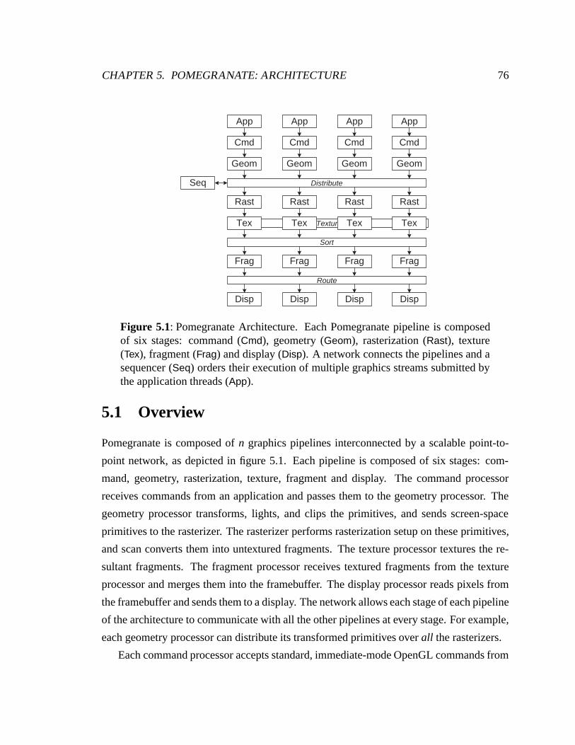
CHAPTER 5. POMEGRANATE: ARCHITECTURE 76
Texture
Seq Distribute
Sort
Route
Geom
Rast
Frag
Cmd
Disp
Tex
App
Geom
Rast
Frag
Cmd
Disp
Tex
App
Geom
Rast
Frag
Cmd
Disp
Tex
App
Geom
Rast
Frag
Cmd
Disp
Tex
App
Figure 5.1: Pomegranate Architecture. Each Pomegranate pipeline is composedof six stages: command (Cmd), geometry (Geom), rasterization (Rast), texture(Tex), fragment (Frag) and display (Disp). A network connects the pipelines and asequencer (Seq) orders their execution of multiple graphics streams submitted bythe application threads (App).
5.1 Overview
Pomegranate is composed of n graphics pipelines interconnected by a scalable point-to-
point network, as depicted in figure 5.1. Each pipeline is composed of six stages: com-
mand, geometry, rasterization, texture, fragment and display. The command processor
receives commands from an application and passes them to the geometry processor. The
geometry processor transforms, lights, and clips the primitives, and sends screen-space
primitives to the rasterizer. The rasterizer performs rasterization setup on these primitives,
and scan converts them into untextured fragments. The texture processor textures the re-
sultant fragments. The fragment processor receives textured fragments from the texture
processor and merges them into the framebuffer. The display processor reads pixels from
the framebuffer and sends them to a display. The network allows each stage of each pipeline
of the architecture to communicate with all the other pipelines at every stage. For example,
each geometry processor can distribute its transformed primitives over all the rasterizers.
Each command processor accepts standard, immediate-mode OpenGL commands from
CHAPTER 5. POMEGRANATE: ARCHITECTURE 77
a single context, as well as parallel API commands for ordering the drawing commands of
the context with the drawing commands of other contexts. As with any parallel system,
Pomegranate will operate efficiently only if the load is balanced across its functional units.
Because graphics primitives can vary substantially in the amount of processing time they
require, and the amount of work a primitive will require is not known a priori, distributing
and balancing this workload in a dynamic fashion while minimizing work replication is a
key innovation of the Pomegranate architecture and directly contributes to its scalability.
Pomegranate performs four main distributions of work: primitives to rasterizers by the ge-
ometry processors; remote texture memory accesses by the texture processors; fragments
to fragment processors by the texture processors; and pixel requests to the fragment proces-
sors by the display engine. Additionally a balanced number of primitives must be provided
to each geometry processor, but that is the responsibility of the application programmer.
Two distinct ordering issues arise in Pomegranate. First, the primitives of a single
graphics context are distributed twice, first over the rasterizers, and then over the fragment
processors. This double distribution results in the work for a single context arriving out of
order at the fragment processors, where it must be reordered. Second, each serial graph-
ics context executes its own commands in order, but it must in turn be interleaved with
the other graphics contexts to provide parallel execution in accordance with any parallel
API commands. A novel serial ordering mechanism is used to maintain the order speci-
fied by the OpenGL command stream, and a novel parallel ordering mechanism is used to
interleave the work of multiple graphics contexts.
By minimizing the use of broadcast communication in both the distribution of work and
the maintenance of order, Pomegranate is able to scale to a high degree of parallelism.
5.2 Scalability and Interface
A fully scalable graphics architecture should provide scalability on the five key metrics
discussed in section 1.2: input rate, triangle rate, rasterization rate, texture memory capacity
and display bandwidth. Pomegranate provides near-linear scalability in all five metrics.
Pomegranate achieves its scalability through a combination of a parallel host interface and
multiple types of communication between the functional units.
CHAPTER 5. POMEGRANATE: ARCHITECTURE 78
• Each geometry processor has a host interface that may receive graphics commands
simultaneously and independently. Ordering constraints between different graphics
contexts may be specified by parallel API commands. This provides scalability of
input rate. Because each geometry processor is limited by the interface speed, there
is no purpose in distributing commands from a single interface across multiple ge-
ometry processors. The application must therefore provide a balanced number of
triangles to each interface. This provides scalability of triangle rate.
• A network port allows each geometry processor to transmit screen-space primitives
to any rasterizer. There is no constraint on this mapping, thus allowing the geometry
processors to load-balance triangle work among rasterizers. This provides scalability
of triangle rate.
• The sequencer, shared among all pipelines, determines the interleaving of the ex-
ecution of the primitives emitted by each geometry processor. It allows multiple
contexts to simultaneously submit commands to the hardware and to have their order
of execution described by the parallel API. This provides scalability of input rate.
• Each rasterizer scan converts screen-space triangles into untextured fragments, and
then passes them to the texture processor where they are textured. The geometry pro-
cessors may load-balance the amount of pixel work sent to each rasterizer in addition
to the number of triangles. The geometry processors may also subdivide large trian-
gles so that their work is distributed over all the rasterizers. This provides scalability
of rasterization rate.
• Textures are distributed in a shared fashion among the pipeline memories, and each
texture processor has a network port for reading and writing of remote textures. This
provides scalability of texture memory capacity.
• Each texture processor has a network port that enables it to route its resultant frag-
ments to the appropriate fragment processor according to screen-space location. This
sorting stage performs the object parallel to image parallel sort, and allows the un-
constrained distribution of triangles between the geometry and rasterization stages
CHAPTER 5. POMEGRANATE: ARCHITECTURE 79
that balances object parallelism. Fine interleaving of the fragment processors load-
balances image parallelism and provides scalability in rasterization rate.
• Each display processor has a network port that allows it to read pixels from all of
the fragment processors and output them to its display. This provides scalability of
display bandwidth.
In addition to scalability, an equally important characteristic of the Pomegranate ar-
chitecture is its compatibility with a modern graphics API. OpenGL has strict ordering
semantics, meaning that all graphics commands must appear to execute in the order they
are specified. For example, two overlapping polygons must appear on the screen in the
order they were submitted by the user, and a state change command applies to all subse-
quent primitives. This constraint forces any parallel OpenGL hardware architecture to be
capable of maintaining the serial order specified by the application. This restriction is one
of the major obstacles to building a scalable OpenGL hardware renderer. As an analogy,
C has become the de facto standard for programming, and as a result microprocessor ar-
chitects focus the bulk of their efforts addressing the difficulties it introduces — pointer
aliasing, limited instruction-level parallelism, strict order of operations, etc. Similarly, we
felt it was important to design within the ordering constraints of OpenGL. In addition to
specifying ordered semantics, OpenGL is an immediate-mode interface. Commands that
are submitted by the application are drawn more or less immediately thereafter. APIs that
are built around display lists, scene graphs, or frame semantics all provide the opportunity
for the hardware to gather up a large number of commands and partition them among its
parallel units. An immediate-mode interface does not enable this approach to extracting
parallelism, and thus provides a further challenge.
5.3 Architecture
We now discuss in detail the different stages of the pipeline and their mechanisms for load-
balancing, and defer the discussion of maintaining a correct serial and parallel order and
the associated sequencer. Figure 5.2 shows the Pomegranate pipeline in detail.
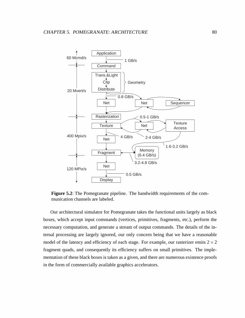
CHAPTER 5. POMEGRANATE: ARCHITECTURE 80
0.8 GB/s
Application
Trans.&Light
Clip
Distribute
Sequencer
TextureTextureAccess
Fragment
Display0.5 GB/s
4 GB/s
1 GB/s
Geometry
2-4 GB/s
0.5-1 GB/s
1.6-3.2 GB/s
Rasterization
Memory(6.4 GB/s)
3.2-4.8 GB/s
Command
Net Net
Net
Net
Net
60 Mcmd/s
20 Mvert/s
400 Mpix/s
120 MPix/s
Figure 5.2: The Pomegranate pipeline. The bandwidth requirements of the com-munication channels are labeled.
Our architectural simulator for Pomegranate takes the functional units largely as black
boxes, which accept input commands (vertices, primitives, fragments, etc.), perform the
necessary computation, and generate a stream of output commands. The details of the in-
ternal processing are largely ignored, our only concern being that we have a reasonable
model of the latency and efficiency of each stage. For example, our rasterizer emits 2×2
fragment quads, and consequently its efficiency suffers on small primitives. The imple-
mentation of these black boxes is taken as a given, and there are numerous existence proofs
in the form of commercially available graphics accelerators.
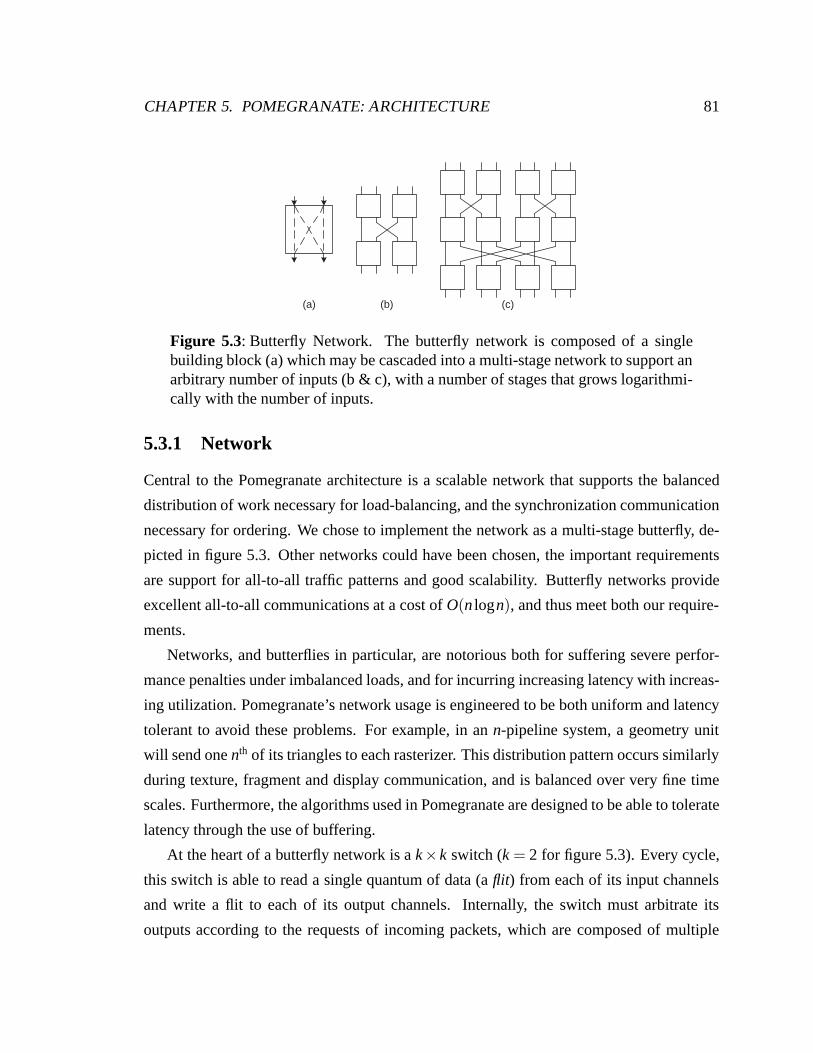
CHAPTER 5. POMEGRANATE: ARCHITECTURE 81
(a) (b) (c)
Figure 5.3: Butterfly Network. The butterfly network is composed of a singlebuilding block (a) which may be cascaded into a multi-stage network to support anarbitrary number of inputs (b & c), with a number of stages that grows logarithmi-cally with the number of inputs.
5.3.1 Network
Central to the Pomegranate architecture is a scalable network that supports the balanced
distribution of work necessary for load-balancing, and the synchronization communication
necessary for ordering. We chose to implement the network as a multi-stage butterfly, de-
picted in figure 5.3. Other networks could have been chosen, the important requirements
are support for all-to-all traffic patterns and good scalability. Butterfly networks provide
excellent all-to-all communications at a cost of O(n logn), and thus meet both our require-
ments.
Networks, and butterflies in particular, are notorious both for suffering severe perfor-
mance penalties under imbalanced loads, and for incurring increasing latency with increas-
ing utilization. Pomegranate’s network usage is engineered to be both uniform and latency
tolerant to avoid these problems. For example, in an n-pipeline system, a geometry unit
will send one nth of its triangles to each rasterizer. This distribution pattern occurs similarly
during texture, fragment and display communication, and is balanced over very fine time
scales. Furthermore, the algorithms used in Pomegranate are designed to be able to tolerate
latency through the use of buffering.
At the heart of a butterfly network is a k×k switch (k = 2 for figure 5.3). Every cycle,
this switch is able to read a single quantum of data (a flit) from each of its input channels
and write a flit to each of its output channels. Internally, the switch must arbitrate its
outputs according to the requests of incoming packets, which are composed of multiple
CHAPTER 5. POMEGRANATE: ARCHITECTURE 82
flits. Channels are virtualized to provide multiple virtual channels per physical channel
to increase the likelihood that an output channel will have a packet that needs it on every
cycle [Dally, 1992]. Virtual channels are critical to large butterfly networks as they increase
bandwidth efficiency from approximately 25% to over 75%.
In order to scale a butterfly network beyond the k inputs and outputs of a single switch,
an additional stage of switches is introduced. The first stage routes based on the most sig-
nificant digits of the destination address, and the second stage routes based on the least
significant digits. An n-interface network may be constructed using logk n stages of n/k
switches. As the number of interfaces increases the aggregate bandwidth available in-
creases linearly, while the cost increases as n logk n.
Pomegranate’s multiple networks are actually virtualized ports within a single unified
network. Two messages from the same source to the same destination, e.g. geometry pro-
cessor 0 to rasterizer 3, are guaranteed to arrive in order, but no other ordering guarantees
are made by the network. A unified network allows the network to be used efficiently for all
types of traffic, rather than having some networks left idle while other networks are over-
loaded with traffic. In order to support the expected workload and network inefficiencies,
each channel runs at 10 Gbyte/sec. Each channel is 32 bits wide and operates at 2.5 GHz.
Each 160-bit flit in our system is transferred over 5 32-bit clocks, and thus the switching
logic runs at 500 MHz. We use 4 × 4 switches and 16 virtual channels per physical channel,
each capable of buffering 16 flits. Ignoring contention, each hop through a switch imposes
8 flits of latency. Packets are constrained to be an integral number of flits, with a 24 bit
header in the first flit, which imposes a small overhead.
5.3.2 Command Processor
The command processor is responsible for the DMA of commands from the application
to the geometry processor, including format conversion of the data. Our interface model,
which we understand to be typical of modern graphics hardware, is based on the construc-
tion of DMA buffers of application commands in host memory. When a buffer fills, or is
flushed, the device driver passes a pointer to the data, along with its length, to the command
processor, which then pulls the data across the interface.
CHAPTER 5. POMEGRANATE: ARCHITECTURE 83
Our host interface bandwidth is 1 Gbyte/sec. This is representative of AGP4x, a current
graphics interface. We model the interface as ideal, with the time to transfer a DMA buffer
dependent only on its length and the bus bandwidth. Our own benchmarks suggest it is
difficult to achieve even 50% utilization of the AGP bus, however, our objective is to study
the scalability and performance of Pomegranate, rather than the host interface.
5.3.3 Geometry Processor
The geometry processor is actually three distinct processors: a transform and lighting en-
gine, a clip processor, and a distribution processor. Each geometry processor supports a
single hardware context, although the context may be virtualized.
The transform and lighting (T&L) engine transforms, culls and lights the primitives.
The T&L engine is implemented as a vertex-parallel vector processor, processing batches
of 16 vertices together. The vertices may all be rejected at multiple points during process-
ing, for example, if they are all outside one of the viewing frustum clip planes, or all of
the primitives they describe are backfacing. Clipping is not performed in the T&L engine
because it introduces a potentially large number of new vertices and corresponding prim-
itives which must be correctly ordered in the primitive stream. Deferring this generally
infrequent operation to a dedicated clip processor greatly simplifies the T&L engine. The
T&L engine has a maximum performance of 20 million transformed and lit vertices per
pipe per second.
The clip processor performs geometric clipping for any primitives that intersect a clip-
ping plane. After geometric clipping, the clip processor subdivides large primitives into
multiple smaller primitives by specifying the primitives multiple times with different ras-
terization bounding boxes. This subdivision ensures that the work of rasterizing a large
triangle can be distributed over all the rasterizers. Large primitives are detected by the
signed area computation of back-face culling and subdivided according to a primitive-
aligned 64×64 stamp. The stamp area was chosen such that a single application submitting
large primitives, such as in a solid-texture application, could keep all of the rasterizers busy.
The clip state for each vertex and the signed area of each primitive is computed by the T&L
CHAPTER 5. POMEGRANATE: ARCHITECTURE 84
engine, so the clip processor’s fast path (no clipping or large primitive subdivision) has al-
most no computation.
The distribution processor distributes the clipped and subdivided primitives to the ras-
terizers. This is Pomegranate’s first stage of general communication. Because the rasteriz-
ers are object parallel, the distribution processor has the freedom to distribute primitives as
it sees fit.
The distribution processors transmit individual vertices with meshing information over
the network to the rasterizers. A vertex with 3D texture coordinates is 228 bits plus 60 bits
for a description of the primitive it is associated with and its rasterization bounding box,
resulting in 320 bit (2 flit) vertex packets. At 20 Mvert/sec, each distribution processor
generates 0.8 Gbyte/sec of network traffic. A distribution processor generates additional
network traffic when large primitives are subdivided to ensure that they present a balanced
load to all the rasterizers. In such cases the additional network traffic is unimportant, as the
system will be rasterization limited.
The distribution processor governs its distribution of work under conflicting goals. It
would like to give the maximum number of sequential triangles to a single rasterizer to
minimize the transmission of mesh vertices multiple times and to maximize the texture
cache efficiency of the rasterizer’s associated texture processor. At the same time it must
minimize the number of triangles and fragments given to each rasterizer to load-balance
the network and allow the reordering algorithm, which relies on buffering proportional to
the granularity of distribution decisions, to be practical.
The distribution processor balances these goals by maintaining a count of the number of
primitives and an estimate of the number of fragments sent to the current rasterizer. When
either of these counts exceeds a limit, the distribution processor starts sending primitives to
a new rasterizer. While the choice of the next rasterizer to use could be based on feedback
from the rasterizers, a simple round-robin mechanism with a triangle limit of 16 and a
fragment limit of 4096 has proven effective in practice. When triangles are small, and thus
each rasterizer gets very few fragments, performance is geometry limited and the resulting
inefficiencies at the texture cache are unimportant. Similarly, when triangles are large, and
each rasterizer gets few triangles, or perhaps even only a piece of a very large triangle,
the performance is rasterization limited and the inefficiency of transmitting each vertex
CHAPTER 5. POMEGRANATE: ARCHITECTURE 85
multiple times is inconsequential.
5.3.4 Rasterizer
The rasterizer scan converts triangles, as well as points and lines, into a stream of fragments
with color, depth and texture coordinates. The rasterizer emits 2× 2 fragment “quads” at
100 MHz and requires 3 cycles for triangle setup, for a peak fill rate of 400 Mpixel/sec.
Partially covered quads can reduce the rasterizer’s efficiency to 100 Mpixel/sec in the worst
case. We achieve 1.47 to 3.95 fragments per quad for the scenes in this thesis. Each
rasterizer receives primitives from all the geometry processors and receives execution order
instructions from the sequencer. The fragment quads emitted by the rasterizer are in turn
textured by the texture processor.
While the geometry processors are each responsible for a single context, the rasterizers
receive primitives from each of the geometry processors, and thus each rasterizer maintains
n contexts, one per geometry processor. The requirement for multiple hardware contexts
per rasterizer and all subsequent stages, as well as the distribution of pipeline configuration
commands, is discussed with other state management issues in section 6.2.
5.3.5 Texture Processor
The texture stage, shown in figure 5.4, consists of two units, the texture processor which
textures the stream of quads generated by the rasterizer, and the texture access unit which
handles texture reads and writes. The input to the rasterization stage has already been load-
balanced by the distribution processors in the geometry stage, so each texture processor
will receive a balanced number of fragments to texture.
In order to provide a scalable texture memory, the texels of each texture are distributed
over all the pipelines in the system. Texture reads, except those that happen to access the
local memory system, involve a round-trip over the network: the request must be sent to the
appropriate texture access unit, and eventually the data are returned. Thus texture accesses
have high latency, in most cases dominated by the network latency. We have previously
demonstrated a prefetching texture cache architecture that can tolerate the high and variable
amount of latency that a system with remote texture accesses, such as Pomegranate, is likely
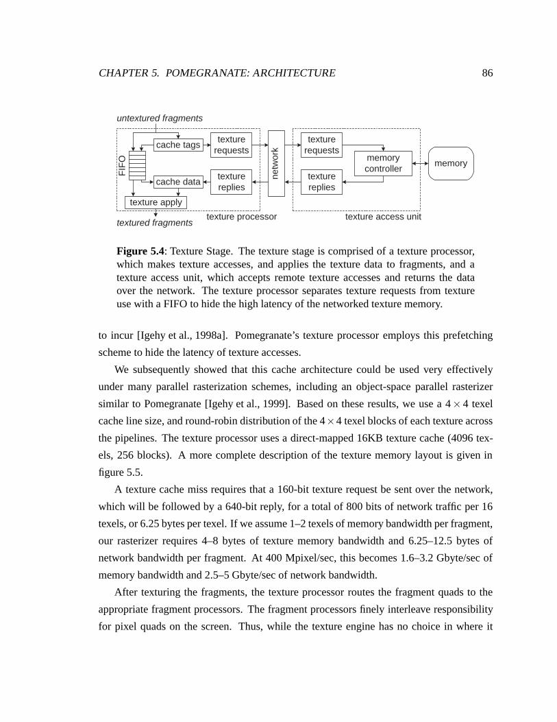
CHAPTER 5. POMEGRANATE: ARCHITECTURE 86
texture apply
cache tags
cache data
texturerequests
texturereplies
texturerequests
texturereplies
memorycontroller
memory
netw
ork
untextured fragments
textured fragmentstexture access unittexture processor
FIF
O
Figure 5.4: Texture Stage. The texture stage is comprised of a texture processor,which makes texture accesses, and applies the texture data to fragments, and atexture access unit, which accepts remote texture accesses and returns the dataover the network. The texture processor separates texture requests from textureuse with a FIFO to hide the high latency of the networked texture memory.
to incur [Igehy et al., 1998a]. Pomegranate’s texture processor employs this prefetching
scheme to hide the latency of texture accesses.
We subsequently showed that this cache architecture could be used very effectively
under many parallel rasterization schemes, including an object-space parallel rasterizer
similar to Pomegranate [Igehy et al., 1999]. Based on these results, we use a 4× 4 texel
cache line size, and round-robin distribution of the 4×4 texel blocks of each texture across
the pipelines. The texture processor uses a direct-mapped 16KB texture cache (4096 tex-
els, 256 blocks). A more complete description of the texture memory layout is given in
figure 5.5.
A texture cache miss requires that a 160-bit texture request be sent over the network,
which will be followed by a 640-bit reply, for a total of 800 bits of network traffic per 16
texels, or 6.25 bytes per texel. If we assume 1–2 texels of memory bandwidth per fragment,
our rasterizer requires 4–8 bytes of texture memory bandwidth and 6.25–12.5 bytes of
network bandwidth per fragment. At 400 Mpixel/sec, this becomes 1.6–3.2 Gbyte/sec of
memory bandwidth and 2.5–5 Gbyte/sec of network bandwidth.
After texturing the fragments, the texture processor routes the fragment quads to the
appropriate fragment processors. The fragment processors finely interleave responsibility
for pixel quads on the screen. Thus, while the texture engine has no choice in where it
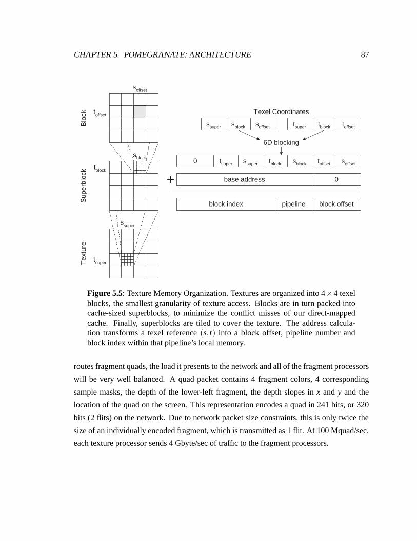
CHAPTER 5. POMEGRANATE: ARCHITECTURE 87
Texel Coordinates
Blo
ckT
extu
reS
uper
bloc
k
soffsetsblockssuper toffsettblocktsuper
toffset soffsetsblocktblocktsuper ssuper0
0base address
pipeline block offsetblock index
6D blocking
soffset
toffset
tblock
sblock
tsuper
ssuper
Figure 5.5: Texture Memory Organization. Textures are organized into 4×4 texelblocks, the smallest granularity of texture access. Blocks are in turn packed intocache-sized superblocks, to minimize the conflict misses of our direct-mappedcache. Finally, superblocks are tiled to cover the texture. The address calcula-tion transforms a texel reference (s, t) into a block offset, pipeline number andblock index within that pipeline’s local memory.
routes fragment quads, the load it presents to the network and all of the fragment processors
will be very well balanced. A quad packet contains 4 fragment colors, 4 corresponding
sample masks, the depth of the lower-left fragment, the depth slopes in x and y and the
location of the quad on the screen. This representation encodes a quad in 241 bits, or 320
bits (2 flits) on the network. Due to network packet size constraints, this is only twice the
size of an individually encoded fragment, which is transmitted as 1 flit. At 100 Mquad/sec,
each texture processor sends 4 Gbyte/sec of traffic to the fragment processors.
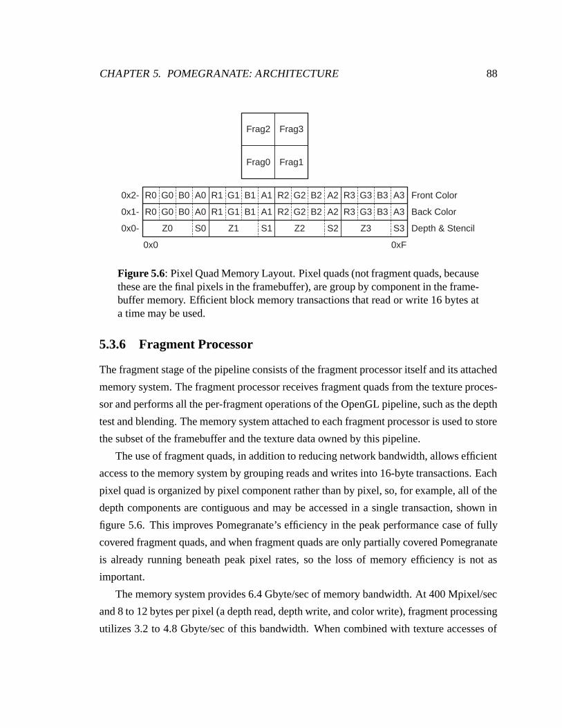
CHAPTER 5. POMEGRANATE: ARCHITECTURE 88
Frag0
Frag2 Frag3
Frag1
Z0
R0 G0 B0 A0
S0
R0 G0 B0 A0
Z1
R1 G1 B1 A1
S1
R1 G1 B1 A1
Z2
R2 G2 B2 A2
S2
R2 G2 B2 A2
Z3
R3 G3 B3 A3
S3
R3 G3 B3 A3 Front Color
Back Color
Depth & Stencil
0x0 0xF
0x0-
0x1-
0x2-
Figure 5.6: Pixel Quad Memory Layout. Pixel quads (not fragment quads, becausethese are the final pixels in the framebuffer), are group by component in the frame-buffer memory. Efficient block memory transactions that read or write 16 bytes ata time may be used.
5.3.6 Fragment Processor
The fragment stage of the pipeline consists of the fragment processor itself and its attached
memory system. The fragment processor receives fragment quads from the texture proces-
sor and performs all the per-fragment operations of the OpenGL pipeline, such as the depth
test and blending. The memory system attached to each fragment processor is used to store
the subset of the framebuffer and the texture data owned by this pipeline.
The use of fragment quads, in addition to reducing network bandwidth, allows efficient
access to the memory system by grouping reads and writes into 16-byte transactions. Each
pixel quad is organized by pixel component rather than by pixel, so, for example, all of the
depth components are contiguous and may be accessed in a single transaction, shown in
figure 5.6. This improves Pomegranate’s efficiency in the peak performance case of fully
covered fragment quads, and when fragment quads are only partially covered Pomegranate
is already running beneath peak pixel rates, so the loss of memory efficiency is not as
important.
The memory system provides 6.4 Gbyte/sec of memory bandwidth. At 400 Mpixel/sec
and 8 to 12 bytes per pixel (a depth read, depth write, and color write), fragment processing
utilizes 3.2 to 4.8 Gbyte/sec of this bandwidth. When combined with texture accesses of
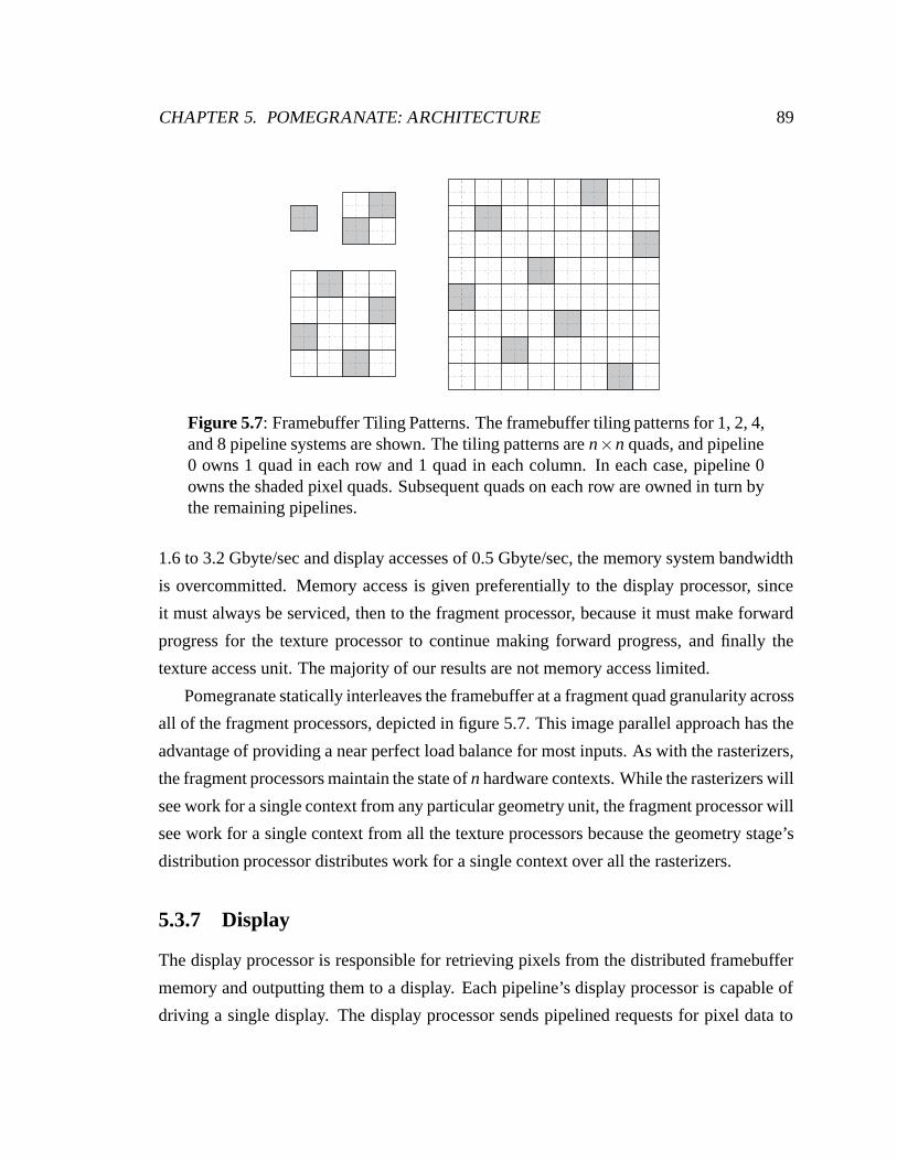
CHAPTER 5. POMEGRANATE: ARCHITECTURE 89
Figure 5.7: Framebuffer Tiling Patterns. The framebuffer tiling patterns for 1, 2, 4,and 8 pipeline systems are shown. The tiling patterns are n×n quads, and pipeline0 owns 1 quad in each row and 1 quad in each column. In each case, pipeline 0owns the shaded pixel quads. Subsequent quads on each row are owned in turn bythe remaining pipelines.
1.6 to 3.2 Gbyte/sec and display accesses of 0.5 Gbyte/sec, the memory system bandwidth
is overcommitted. Memory access is given preferentially to the display processor, since
it must always be serviced, then to the fragment processor, because it must make forward
progress for the texture processor to continue making forward progress, and finally the
texture access unit. The majority of our results are not memory access limited.
Pomegranate statically interleaves the framebuffer at a fragment quad granularity across
all of the fragment processors, depicted in figure 5.7. This image parallel approach has the
advantage of providing a near perfect load balance for most inputs. As with the rasterizers,
the fragment processors maintain the state of n hardware contexts. While the rasterizers will
see work for a single context from any particular geometry unit, the fragment processor will
see work for a single context from all the texture processors because the geometry stage’s
distribution processor distributes work for a single context over all the rasterizers.
5.3.7 Display
The display processor is responsible for retrieving pixels from the distributed framebuffer
memory and outputting them to a display. Each pipeline’s display processor is capable of
driving a single display. The display processor sends pipelined requests for pixel data to
CHAPTER 5. POMEGRANATE: ARCHITECTURE 90
all of the fragment processors, which in turn send back strips of non-adjacent pixels. The
display processor reassembles these into horizontal strips for display. Unlike the use of the
network everywhere else in Pomegranate, the display system is very sensitive to latency
— if pixels arrive late, gaps will appear in the displayed image. We address this issue
with a combination of buffering, which enables the display processor to read ahead several
scanlines, and a priority channel in the network. Dally has shown that a bounded percent-
age of the traffic on a network can be made high priority and delivered with guaranteed
latency [Dally, 1992]. At a display resolution of 1920×1280 and a 72 Hz refresh rate, the
display bandwidth is 0.5 Gbyte/sec, 5% of Pomegranate’s per-pipeline bandwidth.
Chapter 6
Pomegranate: Ordering and State
Ordered execution of the application command stream must be maintained everywhere its
effects are visible to the user. The work distribution algorithms described in the previous
chapter explain how the Pomegranate architecture scales performance, but the constraint
of ordering was ignored. By far the most prevalent place this constraint is exposed is the
OpenGL API itself, which is stateful. For example, a glBlendFunc command modifies the
blending state for all subsequent primitives and for no previous primitives. Second, many
commands (i.e. points, lines, triangles) modify the contents of the framebuffer, and these
modifications must occur in order at each pixel. Finally, changes to the texture memory
must be ordered.
We first describe the mechanisms used to provide ordered execution of a single context,
and the extensions to support the interleaving of multiple contexts subject to the parallel
API. We then discuss Pomegranate’s state management, which relies upon these ordering
mechanisms.
6.1 Ordering
Pomegranate faces two distinct ordering issues. First, the commands for a single context
are distributed over the rasterizers, which in turn sort their fragments to the fragment pro-
cessors. As a result, the original order of execution, while preserved at the rasterizers, is
lost at the fragment processors, as shown in figure 6.1. This two-stage communication
91
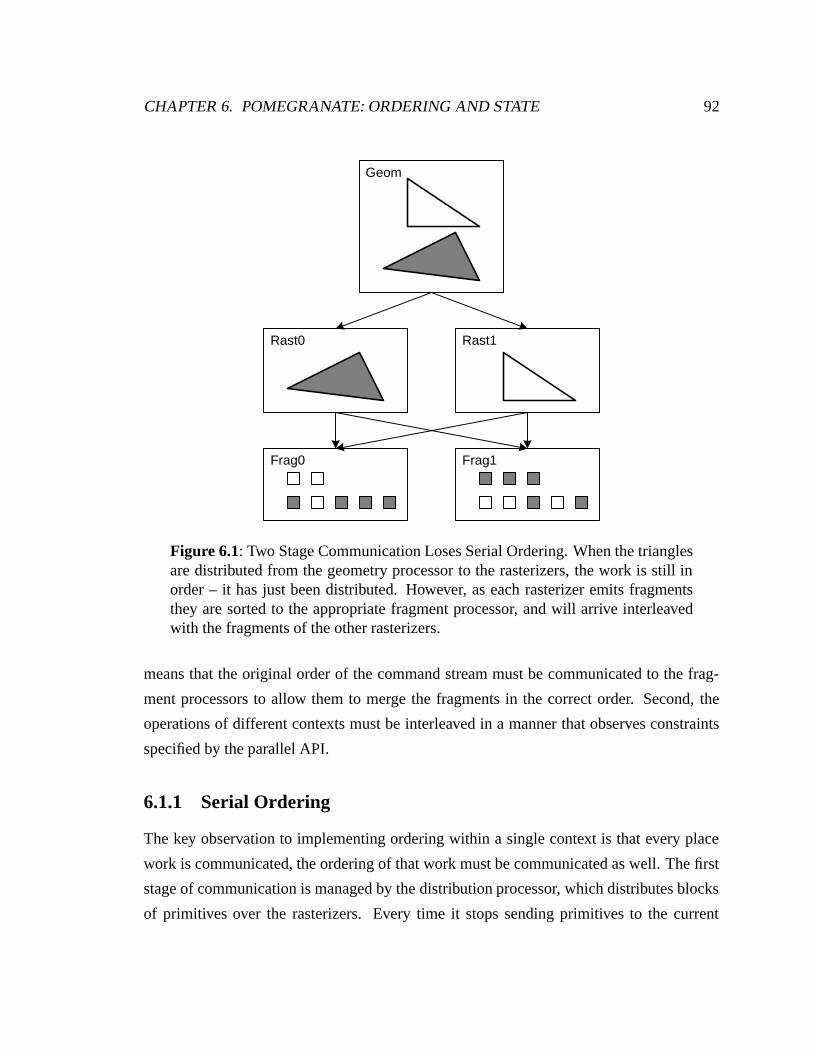
CHAPTER 6. POMEGRANATE: ORDERING AND STATE 92
Geom
Rast0 Rast1
Frag0 Frag1
Figure 6.1: Two Stage Communication Loses Serial Ordering. When the trianglesare distributed from the geometry processor to the rasterizers, the work is still inorder – it has just been distributed. However, as each rasterizer emits fragmentsthey are sorted to the appropriate fragment processor, and will arrive interleavedwith the fragments of the other rasterizers.
means that the original order of the command stream must be communicated to the frag-
ment processors to allow them to merge the fragments in the correct order. Second, the
operations of different contexts must be interleaved in a manner that observes constraints
specified by the parallel API.
6.1.1 Serial Ordering
The key observation to implementing ordering within a single context is that every place
work is communicated, the ordering of that work must be communicated as well. The first
stage of communication is managed by the distribution processor, which distributes blocks
of primitives over the rasterizers. Every time it stops sending primitives to the current
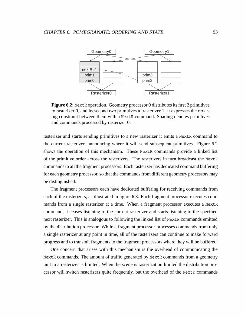
CHAPTER 6. POMEGRANATE: ORDERING AND STATE 93
Geometry0
Rasterizer0
nextR=1prim1prim0
Rasterizer1
prim3prim2
Geometry1
Figure 6.2: NextR operation. Geometry processor 0 distributes its first 2 primitivesto rasterizer 0, and its second two primitives to rasterizer 1. It expresses the order-ing constraint between them with a NextR command. Shading denotes primitivesand commands processed by rasterizer 0.
rasterizer and starts sending primitives to a new rasterizer it emits a NextR command to
the current rasterizer, announcing where it will send subsequent primitives. Figure 6.2
shows the operation of this mechanism. These NextR commands provide a linked list
of the primitive order across the rasterizers. The rasterizers in turn broadcast the NextR
commands to all the fragment processors. Each rasterizer has dedicated command buffering
for each geometry processor, so that the commands from different geometry processors may
be distinguished.
The fragment processors each have dedicated buffering for receiving commands from
each of the rasterizers, as illustrated in figure 6.3. Each fragment processor executes com-
mands from a single rasterizer at a time. When a fragment processor executes a NextR
command, it ceases listening to the current rasterizer and starts listening to the specified
next rasterizer. This is analogous to following the linked list of NextR commands emitted
by the distribution processor. While a fragment processor processes commands from only
a single rasterizer at any point in time, all of the rasterizers can continue to make forward
progress and to transmit fragments to the fragment processors where they will be buffered.
One concern that arises with this mechanism is the overhead of communicating the
NextR commands. The amount of traffic generated by NextR commands from a geometry
unit to a rasterizer is limited. When the scene is rasterization limited the distribution pro-
cessor will switch rasterizers quite frequently, but the overhead of the NextR commands
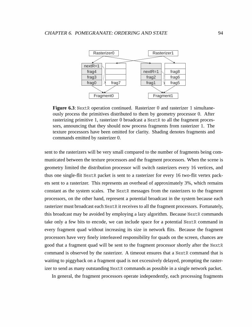
CHAPTER 6. POMEGRANATE: ORDERING AND STATE 94
Rasterizer0
Fragment0
nextR=1
frag3frag0
Rasterizer1
Fragment1
nextR=1frag2frag1
frag4
frag7 frag5frag6frag8
Figure 6.3: NextR operation continued. Rasterizer 0 and rasterizer 1 simultane-ously process the primitives distributed to them by geometry processor 0. Afterrasterizing primitive 1, rasterizer 0 broadcast a NextR to all the fragment proces-sors, announcing that they should now process fragments from rasterizer 1. Thetexture processors have been omitted for clarity. Shading denotes fragments andcommands emitted by rasterizer 0.
sent to the rasterizers will be very small compared to the number of fragments being com-
municated between the texture processors and the fragment processors. When the scene is
geometry limited the distribution processor will switch rasterizers every 16 vertices, and
thus one single-flit NextR packet is sent to a rasterizer for every 16 two-flit vertex pack-
ets sent to a rasterizer. This represents an overhead of approximately 3%, which remains
constant as the system scales. The NextR messages from the rasterizers to the fragment
processors, on the other hand, represent a potential broadcast in the system because each
rasterizer must broadcast each NextR it receives to all the fragment processors. Fortunately,
this broadcast may be avoided by employing a lazy algorithm. Because NextR commands
take only a few bits to encode, we can include space for a potential NextR command in
every fragment quad without increasing its size in network flits. Because the fragment
processors have very finely interleaved responsibility for quads on the screen, chances are
good that a fragment quad will be sent to the fragment processor shortly after the NextR
command is observed by the rasterizer. A timeout ensures that a NextR command that is
waiting to piggyback on a fragment quad is not excessively delayed, prompting the raster-
izer to send as many outstanding NextR commands as possible in a single network packet.
In general, the fragment processors operate independently, each processing fragments
CHAPTER 6. POMEGRANATE: ORDERING AND STATE 95
at its own rate. The exception is when a command observes or modifies shared state be-
yond that on a single fragment processor, in which case the fragment processors must be
synchronized. Pomegranate uses an internal fragment barrier command, BarrierF, to sup-
port this synchronization. For example, glFinish has an implementation similar to this
pseudocode:
glFinish( ) {BarrierFhardware writeback to device driver
}
The BarrierF ensures that all previous operations by this context are complete on all
fragment processors before the writeback signaling completion of the glFinish occurs.
A similar issue arises at the rasterizers. If a command modifies the current texture
state, which is shared among the multiple rasterizers, it must be executed in the correct
serial order with respect to the other commands from that context. Pomegranate enforces
this constraint with an internal BarrierR command which forces all of the rasterizers to
synchronize. A texture modification command can be bracketed between BarrierR com-
mands and thus be made atomic within the hardware. For example, glTexImage2D has an
implementation similar to this pseudocode:
glTexImage2D( ) {BarrierRtexture downloadcache flushBarrierR
}
The initial BarrierR ensures that all previous commands for this context are complete on
all rasterizers before the texture download starts so that the new texture does not appear
on any previous primitives. The final BarrierR ensures no subsequent commands for this
context are executed on any rasterizer before the texture download completes, so that the
old texture does not appear on any subsequent primitives.
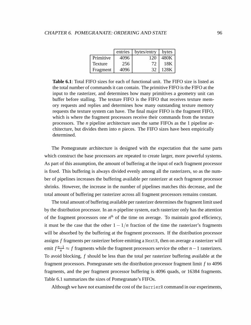
CHAPTER 6. POMEGRANATE: ORDERING AND STATE 96
entries bytes/entry bytesPrimitive 4096 120 480KTexture 256 72 18KFragment 4096 32 128K
Table 6.1: Total FIFO sizes for each of functional unit. The FIFO size is listed asthe total number of commands it can contain. The primitive FIFO is the FIFO at theinput to the rasterizer, and determines how many primitives a geometry unit canbuffer before stalling. The texture FIFO is the FIFO that receives texture mem-ory requests and replies and determines how many outstanding texture memoryrequests the texture system can have. The final major FIFO is the fragment FIFO,which is where the fragment processors receive their commands from the textureprocessors. The n pipeline architecture uses the same FIFOs as the 1 pipeline ar-chitecture, but divides them into n pieces. The FIFO sizes have been empiricallydetermined.
The Pomegranate architecture is designed with the expectation that the same parts
which construct the base processors are repeated to create larger, more powerful systems.
As part of this assumption, the amount of buffering at the input of each fragment processor
is fixed. This buffering is always divided evenly among all the rasterizers, so as the num-
ber of pipelines increases the buffering available per rasterizer at each fragment processor
shrinks. However, the increase in the number of pipelines matches this decrease, and the
total amount of buffering per rasterizer across all fragment processors remains constant.
The total amount of buffering available per rasterizer determines the fragment limit used
by the distribution processor. In an n-pipeline system, each rasterizer only has the attention
of the fragment processors one nth of the time on average. To maintain good efficiency,
it must be the case that the other 1− 1/n fraction of the time the rasterizer’s fragments
will be absorbed by the buffering at the fragment processors. If the distribution processor
assigns f fragments per rasterizer before emitting a NextR, then on average a rasterizer will
emit f n−1n ≈ f fragments while the fragment processors service the other n−1 rasterizers.
To avoid blocking, f should be less than the total per rasterizer buffering available at the
fragment processors. Pomegranate sets the distribution processor fragment limit f to 4096
fragments, and the per fragment processor buffering is 4096 quads, or 16384 fragments.
Table 6.1 summarizes the sizes of Pomegranate’s FIFOs.
Although we have not examined the cost of the BarrierR command in our experiments,
CHAPTER 6. POMEGRANATE: ORDERING AND STATE 97
it clearly may be an expensive operation, because it forces all of the rasterizers to synchro-
nize. Because a geometry processor gives at most f = 4096 fragments to a rasterizer before
switching to a new rasterizer, in the simple case of serial operation the cost of this synchro-
nization is f , the maximum number of fragments assigned to a rasterizer by a geometry
processor, divided by the rasterization rate of 400 Mpixel/sec, or 10µS. This analysis is
complicated by parallel applications, in which the rasterizers are receiving work from mul-
tiple geometry processors, but because the geometry processors are balancing their work
distribution we expect the rasterizers to all encounter the BarrierR command at approxi-
mately the same time, as in the serial case. The potential performance lost to synchronizing
at BarrierF commands is likely much smaller than for BarrierR commands because the
distribution of work over the fragment processors is balanced over very short time scales,
and thus the fragment processors are likely to encounter the BarrierF command at very
nearly the same time.
6.1.2 Parallel Ordering
The internal hardware commands NextR, BarrierR and BarrierF suffice to support se-
rial ordering semantics. The extension of the hardware interface to a parallel API requires
additional support. The parallel API requires that some or all of the graphics resources be
virtualized, and more importantly, subject to preemption and context switching. Imagine
an application of n+1 graphics contexts running on a system that supports only n simulta-
neous contexts. If a graphics barrier is executed by these n+1 contexts, at least one of the
n running contexts must be swapped out to allow the n +1th context to run. Furthermore,
the parallel API introduces the possibility of deadlock. Imagine an incorrectly written
graphics application that executes a glSemaphoreP that never receives a corresponding
glSemaphoreV. At the very least, the system should be able to preempt the deadlocked
graphics context and reclaim those resources. Resolving the preemption problem was one
of the most difficult challenges of the Pomegranate architecture.
One solution to the preemption problem is the ability to read back all of the state of
a hardware context and then restart the context at a later time. Although this may seem
CHAPTER 6. POMEGRANATE: ORDERING AND STATE 98
straightforward, it is a daunting task. Because a context may block at any time, the pre-
empted state of the hardware is complicated by partially processed commands and large
partially-filled FIFOs. As a point of comparison, microprocessor preemption, which has a
much more coherent architecture compared to a graphics system, is generally viewed by
computer architects as a great complication in high-performance microprocessors.
A second approach to the preemption problem is to resolve the API commands in soft-
ware, using the preemption resources of the microprocessor. With this approach, even
though ordering constraints may be specified to the hardware, every piece of work speci-
fied has been guaranteed by the software to eventually execute. Figure 6.4 illustrates this
approach. Each graphics context has an associated submit thread that is responsible for re-
solving the parallel API commands. The application thread communicates with the submit
thread via a FIFO, passing pointers to blocks of OpenGL commands and directly pass-
ing synchronization primitives. If the submit thread sees a pointer to a block of OpenGL
commands, it passes this directly to the hardware. If the submit thread sees a parallel API
command, it actually executes the command, possibly blocking until the synchronization
is resolved. This allows the application thread to continue submitting OpenGL commands
to the FIFO beyond a blocked parallel API command. In addition to executing the par-
allel API command, the submit thread passes the hardware a sequencing command that
maintains the order resolved by the execution of the parallel API command. The important
part of this hardware sequencing command is that even though an ordering is specified,
the commands are guaranteed to be able to drain: the hardware sequencing command for
a glSemaphoreP will not be submitted until the hardware sequencing command for the
corresponding glSemaphoreV is submitted. Thus, a blocked context is blocked entirely in
software, and software context switching and resource reclamation may occur.
In order to keep hardware from constraining the total number of barriers and sema-
phores available to a programmer, the internal hardware sequencing mechanism is based
on a single sequence number per hardware context. Upon executing a glSemaphoreV op-
eration, the submit thread increments the hardware context’s sequence number by one
to indicate a new ordering boundary, annotates the semaphore with a (ctx, seq) pair and
issues an AdvanceContext (ctx, seq) command to the hardware. Upon completing the
glSemaphoreP operation, the signaled submit thread removes the corresponding (ctx , seq)
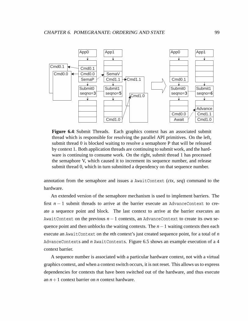
CHAPTER 6. POMEGRANATE: ORDERING AND STATE 99
Cmd0.1
SemaPCmd0.0Cmd0.1
Cmd0.0
Submit0seqno=3
Cmd1.1
App0
SemaVCmd1.1
Submit1seqno=5
App1
Cmd0.0
Cmd0.1
Submit0seqno=3
App0
Submit1seqno=6
App1
Cmd1.0
Cmd1.0
Cmd1.0Cmd1.1Advance
Await
Figure 6.4: Submit Threads. Each graphics context has an associated submitthread which is responsible for resolving the parallel API primitives. On the left,submit thread 0 is blocked waiting to resolve a semaphore P that will be releasedby context 1. Both application threads are continuing to submit work, and the hard-ware is continuing to consume work. On the right, submit thread 1 has processedthe semaphore V, which caused it to increment its sequence number, and releasesubmit thread 0, which in turn submitted a dependency on that sequence number.
annotation from the semaphore and issues a AwaitContext (ctx, seq) command to the
hardware.
An extended version of the semaphore mechanism is used to implement barriers. The
first n − 1 submit threads to arrive at the barrier execute an AdvanceContext to cre-
ate a sequence point and block. The last context to arrive at the barrier executes an
AwaitContext on the previous n− 1 contexts, an AdvanceContext to create its own se-
quence point and then unblocks the waiting contexts. The n−1 waiting contexts then each
execute an AwaitContext on the nth context’s just created sequence point, for a total of n
AdvanceContexts and n AwaitContexts. Figure 6.5 shows an example execution of a 4
context barrier.
A sequence number is associated with a particular hardware context, not with a virtual
graphics context, and when a context switch occurs, it is not reset. This allows us to express
dependencies for contexts that have been switched out of the hardware, and thus execute
an n+1 context barrier on n context hardware.
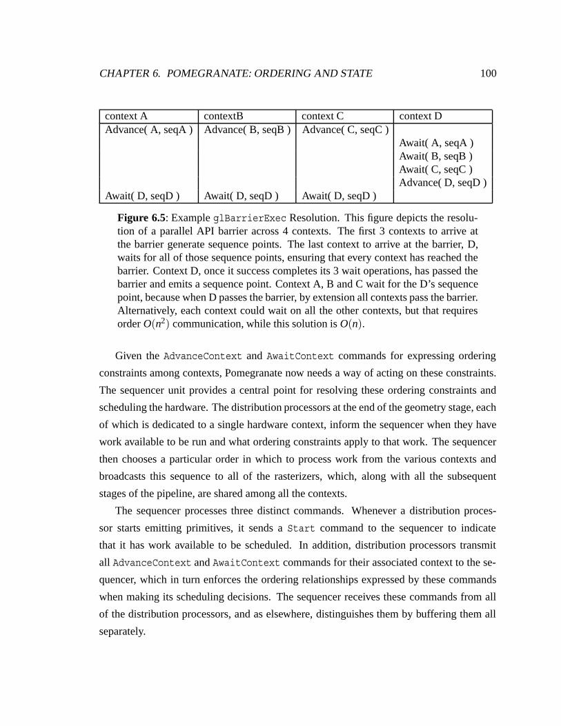
CHAPTER 6. POMEGRANATE: ORDERING AND STATE 100
context A contextB context C context DAdvance( A, seqA ) Advance( B, seqB ) Advance( C, seqC )
Await( A, seqA )Await( B, seqB )Await( C, seqC )Advance( D, seqD )
Await( D, seqD ) Await( D, seqD ) Await( D, seqD )
Figure 6.5: Example glBarrierExec Resolution. This figure depicts the resolu-tion of a parallel API barrier across 4 contexts. The first 3 contexts to arrive atthe barrier generate sequence points. The last context to arrive at the barrier, D,waits for all of those sequence points, ensuring that every context has reached thebarrier. Context D, once it success completes its 3 wait operations, has passed thebarrier and emits a sequence point. Context A, B and C wait for the D’s sequencepoint, because when D passes the barrier, by extension all contexts pass the barrier.Alternatively, each context could wait on all the other contexts, but that requiresorder O(n2) communication, while this solution is O(n).
Given the AdvanceContext and AwaitContext commands for expressing ordering
constraints among contexts, Pomegranate now needs a way of acting on these constraints.
The sequencer unit provides a central point for resolving these ordering constraints and
scheduling the hardware. The distribution processors at the end of the geometry stage, each
of which is dedicated to a single hardware context, inform the sequencer when they have
work available to be run and what ordering constraints apply to that work. The sequencer
then chooses a particular order in which to process work from the various contexts and
broadcasts this sequence to all of the rasterizers, which, along with all the subsequent
stages of the pipeline, are shared among all the contexts.
The sequencer processes three distinct commands. Whenever a distribution proces-
sor starts emitting primitives, it sends a Start command to the sequencer to indicate
that it has work available to be scheduled. In addition, distribution processors transmit
all AdvanceContext and AwaitContext commands for their associated context to the se-
quencer, which in turn enforces the ordering relationships expressed by these commands
when making its scheduling decisions. The sequencer receives these commands from all
of the distribution processors, and as elsewhere, distinguishes them by buffering them all
separately.
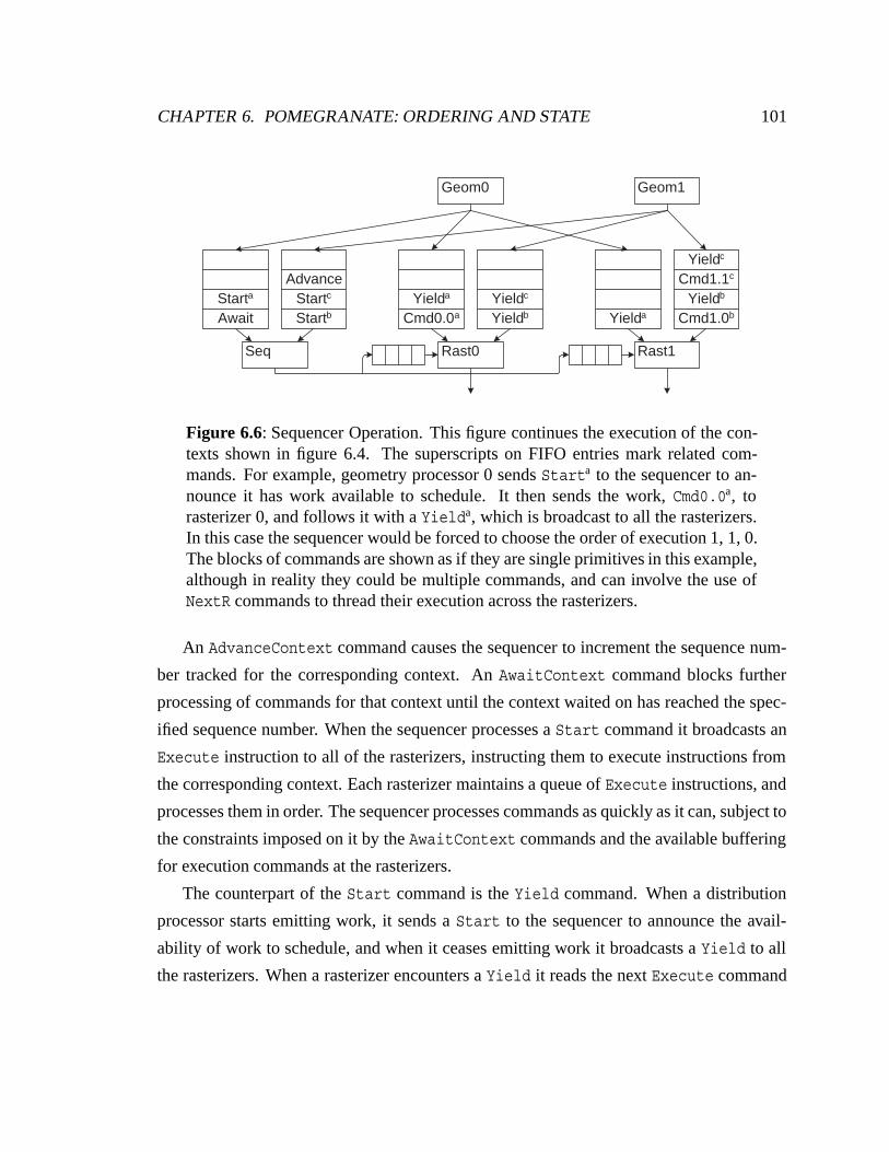
CHAPTER 6. POMEGRANATE: ORDERING AND STATE 101
Geom0 Geom1
Rast0Seq Rast1
AwaitStarta
StartbStartc
Advance
Cmd0.0a
Yielda
Cmd1.0b
Yieldb
Cmd1.1c
Yieldc
YieldaYieldb
Yieldc
Figure 6.6: Sequencer Operation. This figure continues the execution of the con-texts shown in figure 6.4. The superscripts on FIFO entries mark related com-mands. For example, geometry processor 0 sends Starta to the sequencer to an-nounce it has work available to schedule. It then sends the work, Cmd0.0a, torasterizer 0, and follows it with a Yielda, which is broadcast to all the rasterizers.In this case the sequencer would be forced to choose the order of execution 1, 1, 0.The blocks of commands are shown as if they are single primitives in this example,although in reality they could be multiple commands, and can involve the use ofNextR commands to thread their execution across the rasterizers.
An AdvanceContext command causes the sequencer to increment the sequence num-
ber tracked for the corresponding context. An AwaitContext command blocks further
processing of commands for that context until the context waited on has reached the spec-
ified sequence number. When the sequencer processes a Start command it broadcasts an
Execute instruction to all of the rasterizers, instructing them to execute instructions from
the corresponding context. Each rasterizer maintains a queue of Execute instructions, and
processes them in order. The sequencer processes commands as quickly as it can, subject to
the constraints imposed on it by the AwaitContext commands and the available buffering
for execution commands at the rasterizers.
The counterpart of the Start command is the Yield command. When a distribution
processor starts emitting work, it sends a Start to the sequencer to announce the avail-
ability of work to schedule, and when it ceases emitting work it broadcasts a Yield to all
the rasterizers. When a rasterizer encounters a Yield it reads the next Execute command
CHAPTER 6. POMEGRANATE: ORDERING AND STATE 102
from the sequencer and starts executing that context. The Yield command provides con-
text switching points to support ordering and to allow the pipelines to be shared. First, if a
context waits on another context, it must also yield to allow the rasterizers to work on other
contexts, which will eventually allow this context to run again. Second, a context must
occasionally yield voluntarily, to allow the hardware to be shared among all the contexts
so that a single context does not unfairly monopolize the machine. The frequency of these
yields is determined by the relationship of the triangle rate of the geometry units to the com-
mand buffering provided at each rasterizer. In our implementation, a context yields once
it has sent one NextR command to each rasterizer, or has exceeded a fixed timeout since
the last primitive it transmitted, chosen such that it is likely the geometry processor is idle.
Figure 6.6 illustrates the relationship between the sequencer, the geometry (distribution)
processors, and the rasterizers.
The use of a central scheduler, the sequencer, to resolve ordering imposes two limita-
tions on the architecture. First, it limits the minimum efficient amount of work between
Start and Yield commands. Second, it limits the maximum efficient granularity of paral-
lelism.
If too small a granularity of work is used the system is limited by the rate at which
the sequencer can make scheduling decisions and transmit them to the rasterizers. Our
system can make 125 million scheduling decisions a second, which in a full 64-pipeline
system operating at 20 Mtri/sec per pipeline corresponds to approximately a 10-triangle
granularity of work, which is quite small. In reality, the sequencer becomes limited by
the bandwidth of transmitting Execute commands to the rasterizers in this case. Because
the Execute commands are always broadcast, and there are at most 125 million of them a
second, one solution to this limitation would be to introduce a dedicated ring network that
connects the sequencer to all the rasterizers, to allow it to efficiently broadcast Execute
commands.
If too large a granularity of work is chosen by the application, and there is not an ad-
equate amount of available parallelism (for example, the application uses the parallel API
to enforce a total order), then the execution will become serialized, as all of the rasteriz-
ers wait for the primitives being emitted by one geometry processor. This is analogous
to choosing the correct granularity of NextR commands, as discussed in section 6.1.1. In
CHAPTER 6. POMEGRANATE: ORDERING AND STATE 103
this case, the application should use a granularity of parallelism smaller than the amount
of primitive buffering available at the inputs to the rasterizers. We rely on the programmer
to chose an appropriate granularity of parallelism. If the parallel API constrains the hard-
ware to process a large number of primitives from one context before it processes the next
context, nothing can be done to change this.
6.2 State Management
The most difficult issue in state management is maintaining the ordered semantics of the
interface. In the previous section we explained our ordering mechanisms for serial and
parallel contexts. Given those mechanisms, ordering the execution of the state commands
with respect to the primitives they affect is straightforward. Our second issue to deal with
is support for context switching, so the hardware’s physical contexts may be virtualized.
6.2.1 State Commands
State commands modify the configuration of the pipeline, and are ordered with respect to
all other commands. Thus setting the glBlendFunc, for example, affects the compositing
of all subsequent primitives with the framebuffer, but no previous primitives. We maintain
this ordering constraint in Pomegranate by treating state commands just as we treat vertices,
primitives, fragments, and other forms of work that flow through the pipelines. The state
commands are buffered in the input FIFOs to each stage, and executed in order as a result.
A slight complication is introduced by the duplication of contexts in the rasterizers,
texture processors, and fragment processors. Because each rasterizer executes commands
from all of the geometry processors, it must maintain a copy of every context in the system.
Thus, state commands that affect rasterizer or texture processor state must be broadcast by
the geometry processor to all of the rasterizers. Similarly, fragment processor state changes
must be broadcast. However, in this case the broadcast is performed by a texture processor –
there is no need for all of the rasterizers to observe fragment processor state commands. The
geometry processor simply emits fragment processor state commands just like any other
primitive, and whatever rasterizer/texture processor pair happens to receive the command
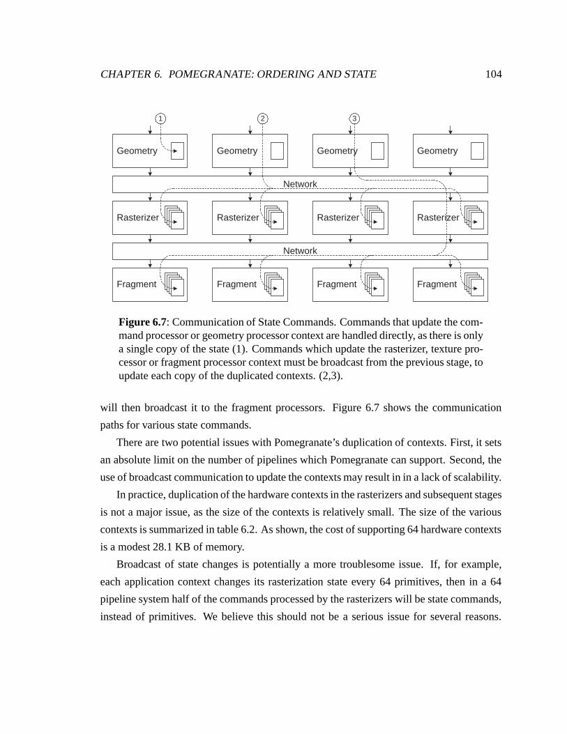
CHAPTER 6. POMEGRANATE: ORDERING AND STATE 104
Rasterizer
Fragment
Geometry Geometry Geometry Geometry
Network
Network
Rasterizer
Fragment
Rasterizer
Fragment
Rasterizer
Fragment
1 2 3
Figure 6.7: Communication of State Commands. Commands that update the com-mand processor or geometry processor context are handled directly, as there is onlya single copy of the state (1). Commands which update the rasterizer, texture pro-cessor or fragment processor context must be broadcast from the previous stage, toupdate each copy of the duplicated contexts. (2,3).
will then broadcast it to the fragment processors. Figure 6.7 shows the communication
paths for various state commands.
There are two potential issues with Pomegranate’s duplication of contexts. First, it sets
an absolute limit on the number of pipelines which Pomegranate can support. Second, the
use of broadcast communication to update the contexts may result in in a lack of scalability.
In practice, duplication of the hardware contexts in the rasterizers and subsequent stages
is not a major issue, as the size of the contexts is relatively small. The size of the various
contexts is summarized in table 6.2. As shown, the cost of supporting 64 hardware contexts
is a modest 28.1 KB of memory.
Broadcast of state changes is potentially a more troublesome issue. If, for example,
each application context changes its rasterization state every 64 primitives, then in a 64
pipeline system half of the commands processed by the rasterizers will be state commands,
instead of primitives. We believe this should not be a serious issue for several reasons.
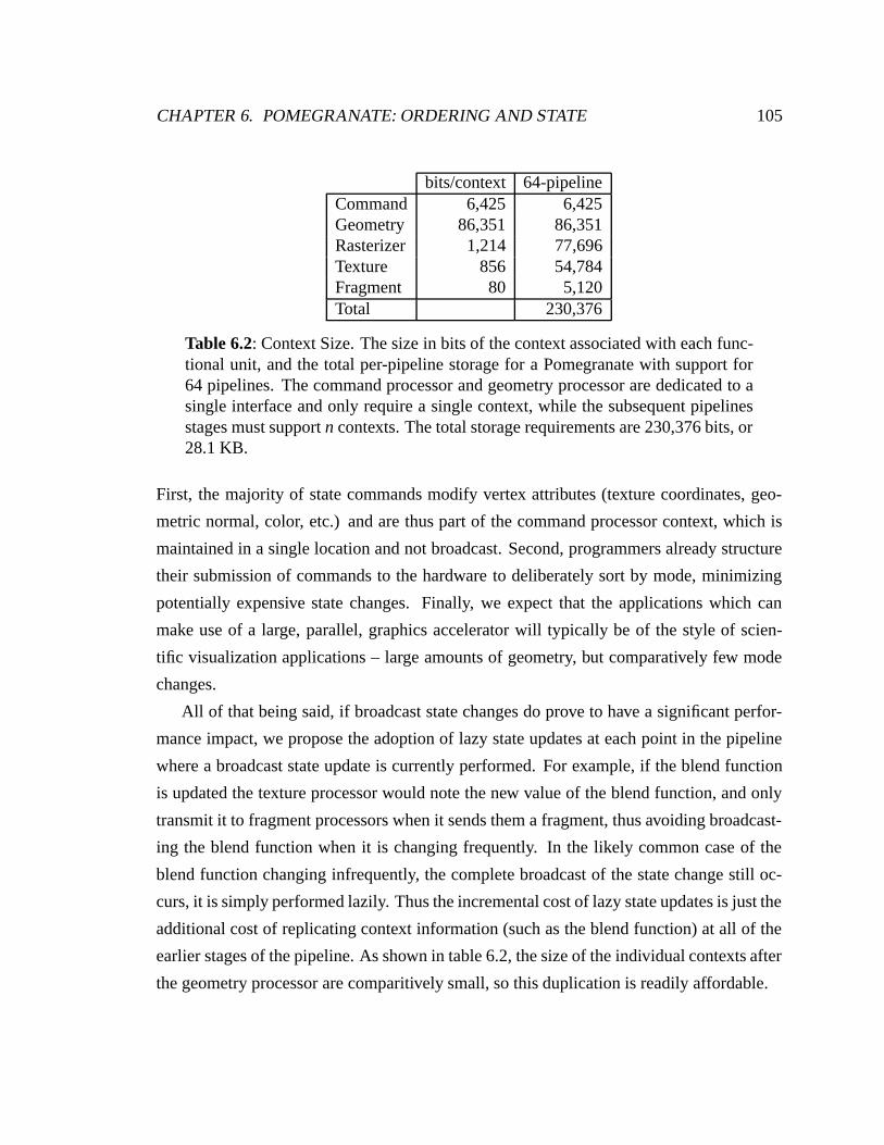
CHAPTER 6. POMEGRANATE: ORDERING AND STATE 105
bits/context 64-pipelineCommand 6,425 6,425Geometry 86,351 86,351Rasterizer 1,214 77,696Texture 856 54,784Fragment 80 5,120Total 230,376
Table 6.2: Context Size. The size in bits of the context associated with each func-tional unit, and the total per-pipeline storage for a Pomegranate with support for64 pipelines. The command processor and geometry processor are dedicated to asingle interface and only require a single context, while the subsequent pipelinesstages must support n contexts. The total storage requirements are 230,376 bits, or28.1 KB.
First, the majority of state commands modify vertex attributes (texture coordinates, geo-
metric normal, color, etc.) and are thus part of the command processor context, which is
maintained in a single location and not broadcast. Second, programmers already structure
their submission of commands to the hardware to deliberately sort by mode, minimizing
potentially expensive state changes. Finally, we expect that the applications which can
make use of a large, parallel, graphics accelerator will typically be of the style of scien-
tific visualization applications – large amounts of geometry, but comparatively few mode
changes.
All of that being said, if broadcast state changes do prove to have a significant perfor-
mance impact, we propose the adoption of lazy state updates at each point in the pipeline
where a broadcast state update is currently performed. For example, if the blend function
is updated the texture processor would note the new value of the blend function, and only
transmit it to fragment processors when it sends them a fragment, thus avoiding broadcast-
ing the blend function when it is changing frequently. In the likely common case of the
blend function changing infrequently, the complete broadcast of the state change still oc-
curs, it is simply performed lazily. Thus the incremental cost of lazy state updates is just the
additional cost of replicating context information (such as the blend function) at all of the
earlier stages of the pipeline. As shown in table 6.2, the size of the individual contexts after
the geometry processor are comparitively small, so this duplication is readily affordable.
CHAPTER 6. POMEGRANATE: ORDERING AND STATE 106
6.2.2 Context Switching
Context switching has historically been a sticking point in graphics architecture, although
its importance has long been recognized. Voorhies, Kirk and Lathrop discuss the advan-
tages of providing graphics as a “virtual system resource”, and stress that the key to virtual-
izing the graphics system is to “switch low-level contexts rapidly” [Voorhies et al., 1988].
Context switching can be implemented in a number of fashions. One approach is to
shadow all of the graphics state in software, in which case context switching is as simple
as submitting state commands to make the hardware reflect the new context. Shadowing
the state of every graphics command in software would be very expensive however, partic-
ularly since some state, notably the vertex attributes, is expected to change very frequently.
Because the hardware must maintain the context, another possible approach is to read back
the context from the hardware. Thus, while context switches are now somewhat more
expensive (as they require a round-trip to the hardware), the common case of command
submission is significantly faster. Many architectures directly use the second approach, but
unfortunately things are not quite that simple for Pomegranate.
Pomegranate’s implementation of the parallel API has major ramifications for context
switching. Unlike a graphics system with a serial interface, application commands may
not be able to complete without a context switch. For example, a barrier of n +1 contexts
executing on n context hardware requires context switching. Thus context switching can
not be executed simply by allowing all previous commands to complete execution and then
reading back the hardware state, because those commands may be blocked from comple-
tion. Part of our motivation for introducing the submit threads was to insure that commands
submitted to the hardware (versus those buffered, but waiting for submission by the submit
threads) are guaranteed to drain, so we will never deadlock the hardware.
We propose the following solution to address context switching on Pomegranate. Each
application process with a bound graphics context (and thus a potential user of a hardware
graphics context) has its own independent submit thread. Each hardware context has an
associated lock, and when the submit thread wishes to submit a block of work to the hard-
ware, it must first acquire the appropriate hardware lock. The lock guards both access to the
hardware and to a shared variable which indicates what submit thread currently owns this
CHAPTER 6. POMEGRANATE: ORDERING AND STATE 107
context. A submit thread which does not currently own a hardware context may context
switch by acquiring the lock for a hardware context, and then, while holding the lock, read-
ing back the hardware state of the context and saving it away for the previous submit thread
owner, and finally updating the shared variable to indicate it owns the context. The pre-
empting submit thread then updates the hardware with its context, which was saved away
the last time it was context switched, and resumes submission of application commands.
In this scheme every time the hardware is touched a lock must be acquired, but we
believe this will not have any significant performance impact, because the lock needs to
be acquired only per command block, which greatly amortizes the cost of lock acquisi-
tion. Furthermore, with an appropriate choice of mechanism, the acquisition of the lock
by the thread which currently owns the hardware context can be made very fast. Addition-
ally, we can reduce the cost of the context switch by hiding the readback. The preempting
thread does not need to wait for the readback of the previous thread’s context. As long as
the readback is performed in order, before the commands which set the state for the pre-
empting context, the readback may happen asynchronously. Whether the state is read back
synchronously or asynchronously, some care must be taken to insure that the preempted
submit thread does not preempt another context and start executing again before its state
has been returned. Similarly, a sequence point must be created to insure that when the
preempted context does start executing again the commands it submits on the new hard-
ware context remain ordered behind the commands it submitted on its previous hardware
context.
Given this mechanism, an appropriate policy must also be chosen for context switch-
ing the hardware. Without some care, two submit threads could spend all of their time
passing a hardware context back and forth, neither of them making any progress. One pos-
sible solution is to include a timer, so that a submit thread will always preempt the submit
thread which has owned its hardware context the longest. Alternatively, simply preempt-
ing a random context, as long as it has owned the hardware for some minimum number of
milliseconds, would likely work well.
Chapter 7
Simulation and Results
We have implemented an OpenGL software device driver and hardware simulator to verify
our architecture. Our system supports all of the major functionality of OpenGL.
The Pomegranate hardware is modeled under an event-driven simulator. The simulator
is composed of multiple independent threads of execution which communicate with each
other via events. Threads advance events and await on events to coordinate their execution.
The simulator provides a shared global knowledge of time, so threads may both wait for
other threads to complete a task, as well as simply wait for time to pass to model clock
cycles, etc. The simulator is non-preemptive and a particular thread of execution ceases
execution only when it explicitly waits for time to pass or waits on an event.
Our simulator masquerades as the system OpenGL dynamic library on Microsoft Win-
dows NT and SGI IRIX operating systems. Application parallelism is supported through
additional functions exported by our OpenGL library that allow the creation of user threads
within our simulator. This simulation methodology allows us to deterministically simulate
Pomegranate, which aids both debugging and analysis of performance. In particular, per-
formance problems can be iteratively analyzed by enabling more and more instrumentation
in different areas of the hardware, with the confidence that subsequent runs will behave
identically.
We analyzed Pomegranate’s performance with three applications, shown in table 7.1.
The first, March, is a parallel implementation of marching cubes [Lorensen and Cline, 1987].
108
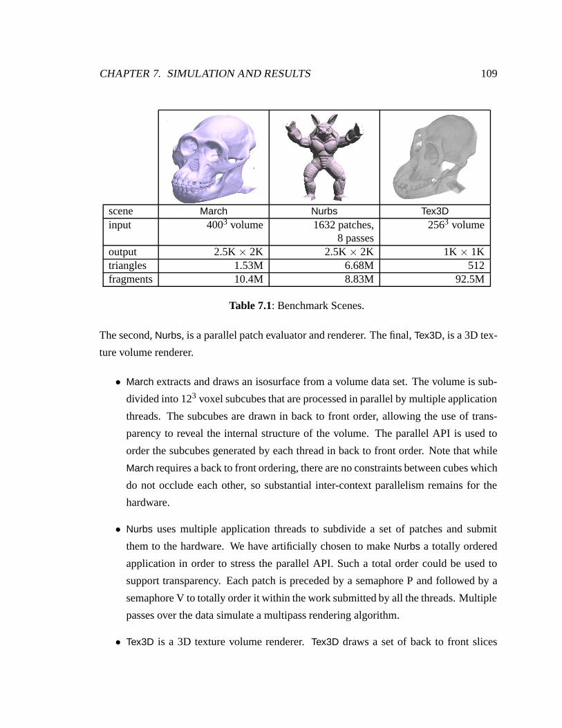
CHAPTER 7. SIMULATION AND RESULTS 109
scene March Nurbs Tex3Dinput 4003 volume 1632 patches, 2563 volume
8 passesoutput 2.5K × 2K 2.5K × 2K 1K × 1Ktriangles 1.53M 6.68M 512fragments 10.4M 8.83M 92.5M
Table 7.1: Benchmark Scenes.
The second, Nurbs, is a parallel patch evaluator and renderer. The final, Tex3D, is a 3D tex-
ture volume renderer.
• March extracts and draws an isosurface from a volume data set. The volume is sub-
divided into 123 voxel subcubes that are processed in parallel by multiple application
threads. The subcubes are drawn in back to front order, allowing the use of trans-
parency to reveal the internal structure of the volume. The parallel API is used to
order the subcubes generated by each thread in back to front order. Note that while
March requires a back to front ordering, there are no constraints between cubes which
do not occlude each other, so substantial inter-context parallelism remains for the
hardware.
• Nurbs uses multiple application threads to subdivide a set of patches and submit
them to the hardware. We have artificially chosen to make Nurbs a totally ordered
application in order to stress the parallel API. Such a total order could be used to
support transparency. Each patch is preceded by a semaphore P and followed by a
semaphore V to totally order it within the work submitted by all the threads. Multiple
passes over the data simulate a multipass rendering algorithm.
• Tex3D is a 3D texture volume renderer. Tex3D draws a set of back to front slices
CHAPTER 7. SIMULATION AND RESULTS 110
through the volume perpendicular to the viewing axis. Tex3D represents a serial
application with very high fill rate demands and low geometry demands, and is an
example of a serial application that can successfully drive the hardware at a high
degree of parallelism.
We measure Pomegranate’s performance on these scenes in four ways. First we ex-
amine Pomegranate’s raw scalability, the speedup we achieved as a function of the num-
ber of pipelines. Next we examine the load imbalance across the functional units, which
will determine the best achievable speedup for our parallel system. Then we quantify the
network bandwidth demanded by the different stages of the pipeline and analyze the lost
performance due to network imbalance. Finally we compare Pomegranate’s performance
to simulations of sort-first, sort-middle and sort-last architectures.
7.1 Scalability
Our first measure of parallel performance is speedup, presented for our scenes in figure 7.1.
Nurbs exhibits excellent scalability, despite presenting a totally ordered set of commands to
the hardware. At 64 processors the hardware is operating at 99% parallel efficiency, with a
triangle rate of 1.10 Gtri/sec and a fill rate of 1.46 Gpixel/sec. The only application tuning
necessary to achieve this level of performance is picking an appropriate granularity of syn-
chronization. Because Nurbs submits all of its primitives in a total order, the sequencer has
no available parallel work to schedule, and is always completely constrained by the API.
This results in only 1 geometry unit being schedulable at any point in time, and the other
geometry units will make forward progress only while there is adequate buffering at the
rasterizers and fragment processors to receive their commands.
March runs at a peak of 595 Mtri/sec and 4.05 Gpixel/sec in a 64-pipeline architecture,
a 57× speedup over a single pipeline architecture. While this scalability is excellent, it is
substantially less than that of Nurbs. If we examine the granularity of synchronization, the
problem becomes apparent. Nurbs executes a semaphore pair for every patch of the model,
which corresponds to every 512 triangles. March, on the other hand, executes 3 semaphore
pairs for every 123 voxel subcube of the volume, and the average subcube only contains
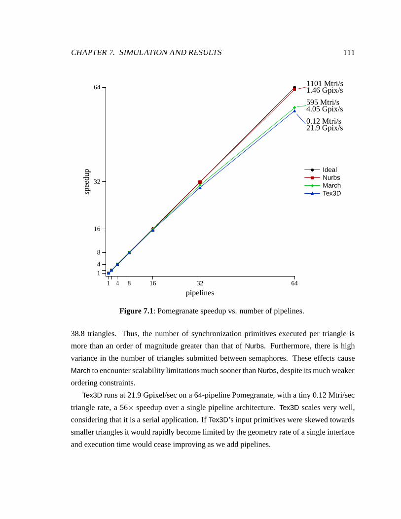
CHAPTER 7. SIMULATION AND RESULTS 111
1 4 8 16 32 64
pipelines
14
8
16
32
64sp
eedu
p IdealNurbsMarchTex3D
1101 Mtri/s1.46 Gpix/s
595 Mtri/s4.05 Gpix/s
0.12 Mtri/s21.9 Gpix/s
Figure 7.1: Pomegranate speedup vs. number of pipelines.
38.8 triangles. Thus, the number of synchronization primitives executed per triangle is
more than an order of magnitude greater than that of Nurbs. Furthermore, there is high
variance in the number of triangles submitted between semaphores. These effects cause
March to encounter scalability limitations much sooner than Nurbs, despite its much weaker
ordering constraints.
Tex3D runs at 21.9 Gpixel/sec on a 64-pipeline Pomegranate, with a tiny 0.12 Mtri/sec
triangle rate, a 56× speedup over a single pipeline architecture. Tex3D scales very well,
considering that it is a serial application. If Tex3D’s input primitives were skewed towards
smaller triangles it would rapidly become limited by the geometry rate of a single interface
and execution time would cease improving as we add pipelines.
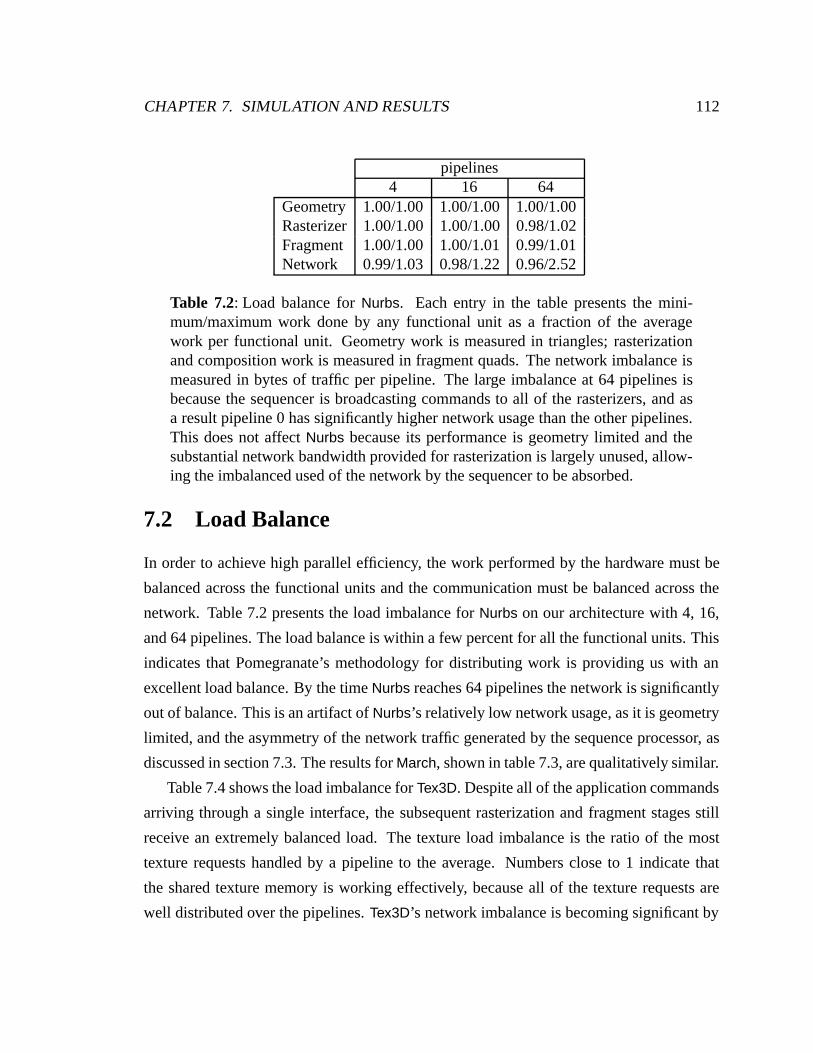
CHAPTER 7. SIMULATION AND RESULTS 112
pipelines4 16 64
Geometry 1.00/1.00 1.00/1.00 1.00/1.00Rasterizer 1.00/1.00 1.00/1.00 0.98/1.02Fragment 1.00/1.00 1.00/1.01 0.99/1.01Network 0.99/1.03 0.98/1.22 0.96/2.52
Table 7.2: Load balance for Nurbs. Each entry in the table presents the mini-mum/maximum work done by any functional unit as a fraction of the averagework per functional unit. Geometry work is measured in triangles; rasterizationand composition work is measured in fragment quads. The network imbalance ismeasured in bytes of traffic per pipeline. The large imbalance at 64 pipelines isbecause the sequencer is broadcasting commands to all of the rasterizers, and asa result pipeline 0 has significantly higher network usage than the other pipelines.This does not affect Nurbs because its performance is geometry limited and thesubstantial network bandwidth provided for rasterization is largely unused, allow-ing the imbalanced used of the network by the sequencer to be absorbed.
7.2 Load Balance
In order to achieve high parallel efficiency, the work performed by the hardware must be
balanced across the functional units and the communication must be balanced across the
network. Table 7.2 presents the load imbalance for Nurbs on our architecture with 4, 16,
and 64 pipelines. The load balance is within a few percent for all the functional units. This
indicates that Pomegranate’s methodology for distributing work is providing us with an
excellent load balance. By the time Nurbs reaches 64 pipelines the network is significantly
out of balance. This is an artifact of Nurbs’s relatively low network usage, as it is geometry
limited, and the asymmetry of the network traffic generated by the sequence processor, as
discussed in section 7.3. The results for March, shown in table 7.3, are qualitatively similar.
Table 7.4 shows the load imbalance for Tex3D. Despite all of the application commands
arriving through a single interface, the subsequent rasterization and fragment stages still
receive an extremely balanced load. The texture load imbalance is the ratio of the most
texture requests handled by a pipeline to the average. Numbers close to 1 indicate that
the shared texture memory is working effectively, because all of the texture requests are
well distributed over the pipelines. Tex3D’s network imbalance is becoming significant by
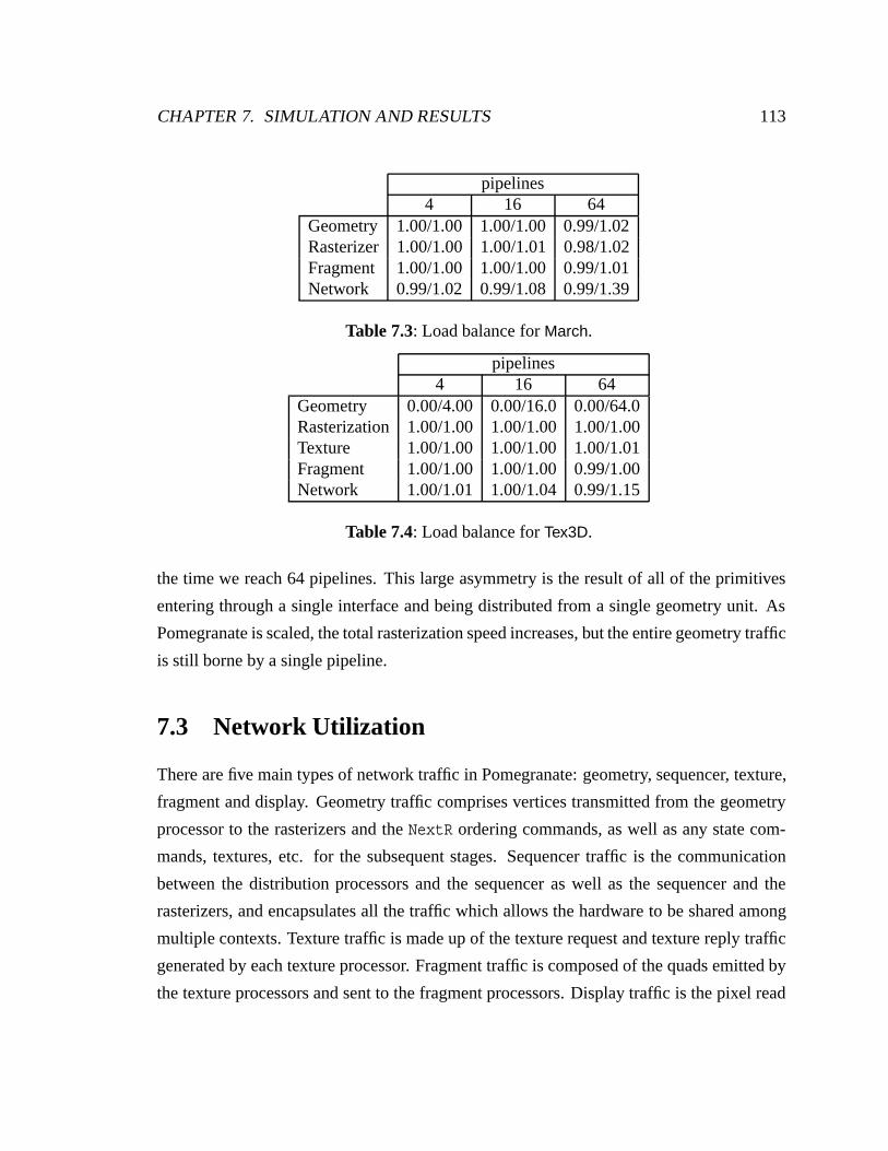
CHAPTER 7. SIMULATION AND RESULTS 113
pipelines4 16 64
Geometry 1.00/1.00 1.00/1.00 0.99/1.02Rasterizer 1.00/1.00 1.00/1.01 0.98/1.02Fragment 1.00/1.00 1.00/1.00 0.99/1.01Network 0.99/1.02 0.99/1.08 0.99/1.39
Table 7.3: Load balance for March.
pipelines4 16 64
Geometry 0.00/4.00 0.00/16.0 0.00/64.0Rasterization 1.00/1.00 1.00/1.00 1.00/1.00Texture 1.00/1.00 1.00/1.00 1.00/1.01Fragment 1.00/1.00 1.00/1.00 0.99/1.00Network 1.00/1.01 1.00/1.04 0.99/1.15
Table 7.4: Load balance for Tex3D.
the time we reach 64 pipelines. This large asymmetry is the result of all of the primitives
entering through a single interface and being distributed from a single geometry unit. As
Pomegranate is scaled, the total rasterization speed increases, but the entire geometry traffic
is still borne by a single pipeline.
7.3 Network Utilization
There are five main types of network traffic in Pomegranate: geometry, sequencer, texture,
fragment and display. Geometry traffic comprises vertices transmitted from the geometry
processor to the rasterizers and the NextR ordering commands, as well as any state com-
mands, textures, etc. for the subsequent stages. Sequencer traffic is the communication
between the distribution processors and the sequencer as well as the sequencer and the
rasterizers, and encapsulates all the traffic which allows the hardware to be shared among
multiple contexts. Texture traffic is made up of the texture request and texture reply traffic
generated by each texture processor. Fragment traffic is composed of the quads emitted by
the texture processors and sent to the fragment processors. Display traffic is the pixel read
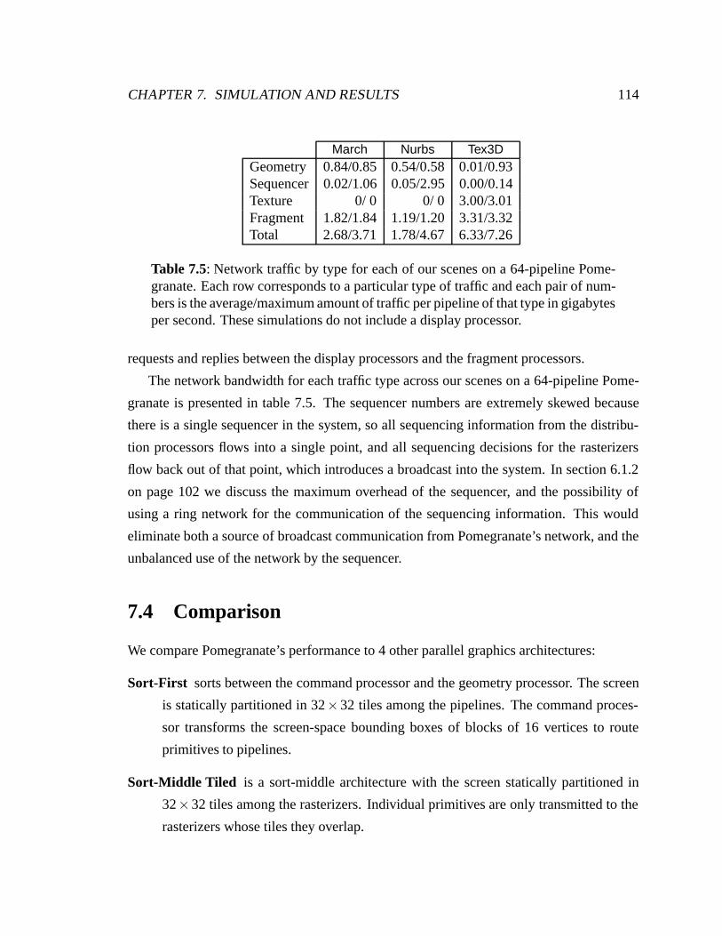
CHAPTER 7. SIMULATION AND RESULTS 114
March Nurbs Tex3DGeometry 0.84/0.85 0.54/0.58 0.01/0.93Sequencer 0.02/1.06 0.05/2.95 0.00/0.14Texture 0/ 0 0/ 0 3.00/3.01Fragment 1.82/1.84 1.19/1.20 3.31/3.32Total 2.68/3.71 1.78/4.67 6.33/7.26
Table 7.5: Network traffic by type for each of our scenes on a 64-pipeline Pome-granate. Each row corresponds to a particular type of traffic and each pair of num-bers is the average/maximum amount of traffic per pipeline of that type in gigabytesper second. These simulations do not include a display processor.
requests and replies between the display processors and the fragment processors.
The network bandwidth for each traffic type across our scenes on a 64-pipeline Pome-
granate is presented in table 7.5. The sequencer numbers are extremely skewed because
there is a single sequencer in the system, so all sequencing information from the distribu-
tion processors flows into a single point, and all sequencing decisions for the rasterizers
flow back out of that point, which introduces a broadcast into the system. In section 6.1.2
on page 102 we discuss the maximum overhead of the sequencer, and the possibility of
using a ring network for the communication of the sequencing information. This would
eliminate both a source of broadcast communication from Pomegranate’s network, and the
unbalanced use of the network by the sequencer.
7.4 Comparison
We compare Pomegranate’s performance to 4 other parallel graphics architectures:
Sort-First sorts between the command processor and the geometry processor. The screen
is statically partitioned in 32×32 tiles among the pipelines. The command proces-
sor transforms the screen-space bounding boxes of blocks of 16 vertices to route
primitives to pipelines.
Sort-Middle Tiled is a sort-middle architecture with the screen statically partitioned in
32×32 tiles among the rasterizers. Individual primitives are only transmitted to the
rasterizers whose tiles they overlap.
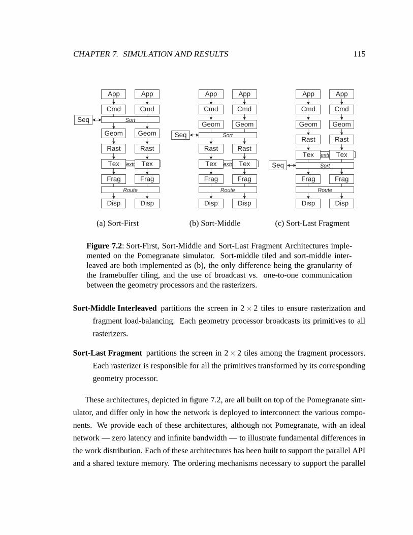
CHAPTER 7. SIMULATION AND RESULTS 115
Texture
Geom
Rast
Frag
Cmd
Disp
Seq
Tex
Geom
Rast
Frag
Cmd
Disp
Tex
App App
Sort
Route
(a) Sort-First
Texture
Geom
Rast
Frag
Cmd
Disp
Seq
Tex
Geom
Rast
Frag
Cmd
Disp
Tex
App App
Route
Sort
(b) Sort-Middle
Texture
Geom
Rast
Frag
Cmd
Disp
Seq
Tex
Geom
Rast
Frag
Cmd
Disp
Tex
App App
Sort
Route
(c) Sort-Last Fragment
Figure 7.2: Sort-First, Sort-Middle and Sort-Last Fragment Architectures imple-mented on the Pomegranate simulator. Sort-middle tiled and sort-middle inter-leaved are both implemented as (b), the only difference being the granularity ofthe framebuffer tiling, and the use of broadcast vs. one-to-one communicationbetween the geometry processors and the rasterizers.
Sort-Middle Interleaved partitions the screen in 2× 2 tiles to ensure rasterization and
fragment load-balancing. Each geometry processor broadcasts its primitives to all
rasterizers.
Sort-Last Fragment partitions the screen in 2× 2 tiles among the fragment processors.
Each rasterizer is responsible for all the primitives transformed by its corresponding
geometry processor.
These architectures, depicted in figure 7.2, are all built on top of the Pomegranate sim-
ulator, and differ only in how the network is deployed to interconnect the various compo-
nents. We provide each of these architectures, although not Pomegranate, with an ideal
network — zero latency and infinite bandwidth — to illustrate fundamental differences in
the work distribution. Each of these architectures has been built to support the parallel API
and a shared texture memory. The ordering mechanisms necessary to support the parallel
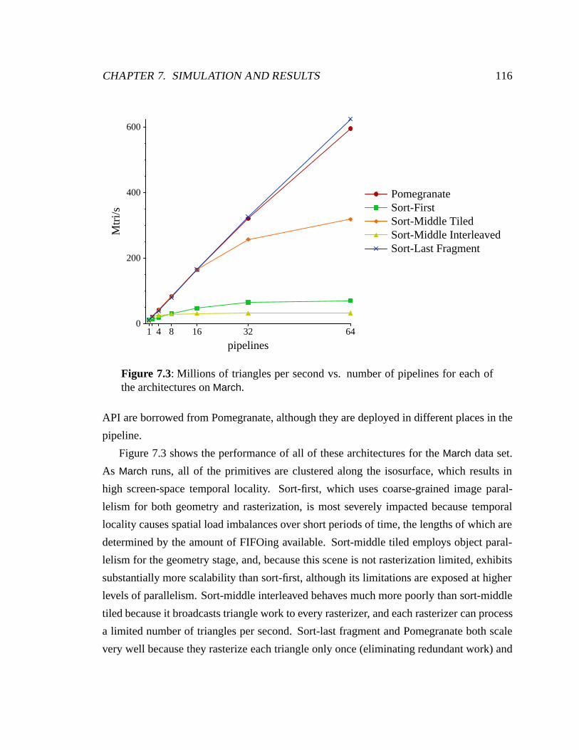
CHAPTER 7. SIMULATION AND RESULTS 116
1 4 8 16 32 64
pipelines
0
200
400
600M
tri/s
PomegranateSort-FirstSort-Middle TiledSort-Middle InterleavedSort-Last Fragment
Figure 7.3: Millions of triangles per second vs. number of pipelines for each ofthe architectures on March.
API are borrowed from Pomegranate, although they are deployed in different places in the
pipeline.
Figure 7.3 shows the performance of all of these architectures for the March data set.
As March runs, all of the primitives are clustered along the isosurface, which results in
high screen-space temporal locality. Sort-first, which uses coarse-grained image paral-
lelism for both geometry and rasterization, is most severely impacted because temporal
locality causes spatial load imbalances over short periods of time, the lengths of which are
determined by the amount of FIFOing available. Sort-middle tiled employs object paral-
lelism for the geometry stage, and, because this scene is not rasterization limited, exhibits
substantially more scalability than sort-first, although its limitations are exposed at higher
levels of parallelism. Sort-middle interleaved behaves much more poorly than sort-middle
tiled because it broadcasts triangle work to every rasterizer, and each rasterizer can process
a limited number of triangles per second. Sort-last fragment and Pomegranate both scale
very well because they rasterize each triangle only once (eliminating redundant work) and
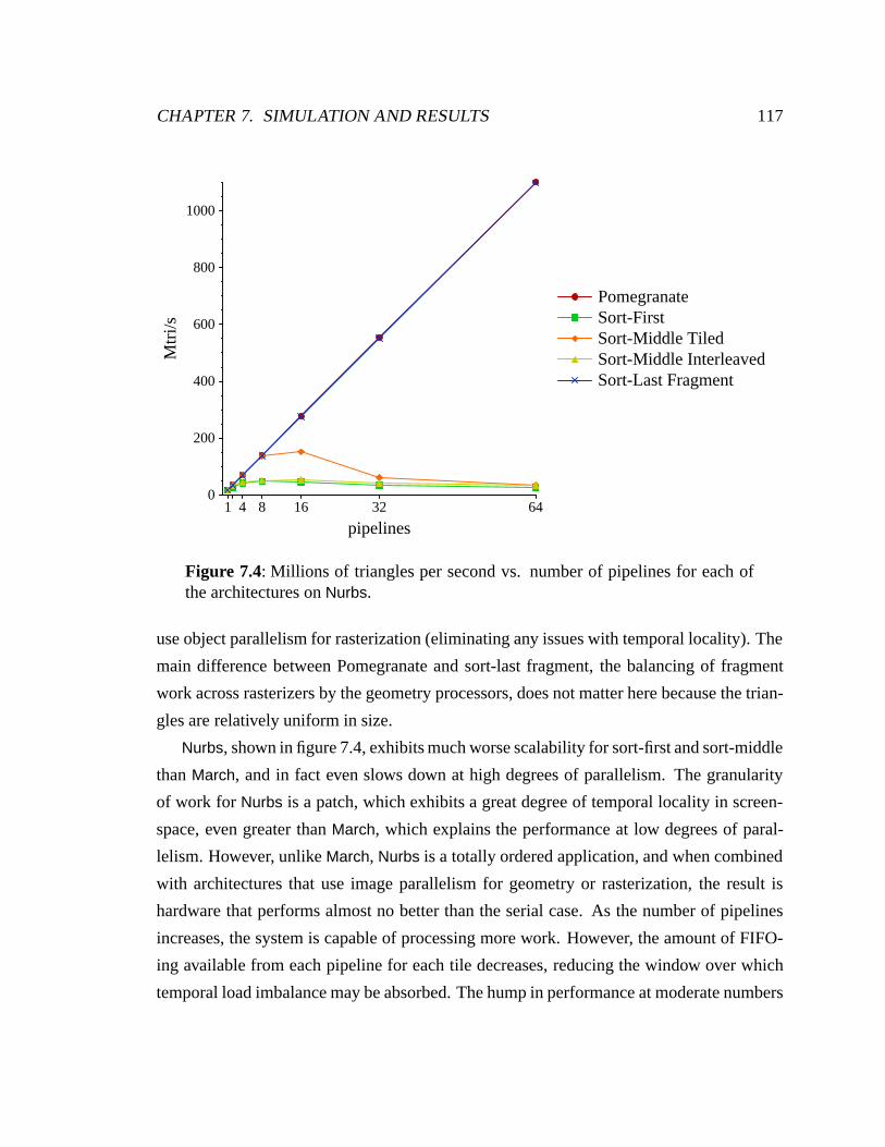
CHAPTER 7. SIMULATION AND RESULTS 117
1 4 8 16 32 64
pipelines
0
200
400
600
800
1000
Mtr
i/s
PomegranateSort-FirstSort-Middle TiledSort-Middle InterleavedSort-Last Fragment
Figure 7.4: Millions of triangles per second vs. number of pipelines for each ofthe architectures on Nurbs.
use object parallelism for rasterization (eliminating any issues with temporal locality). The
main difference between Pomegranate and sort-last fragment, the balancing of fragment
work across rasterizers by the geometry processors, does not matter here because the trian-
gles are relatively uniform in size.
Nurbs, shown in figure 7.4, exhibits much worse scalability for sort-first and sort-middle
than March, and in fact even slows down at high degrees of parallelism. The granularity
of work for Nurbs is a patch, which exhibits a great degree of temporal locality in screen-
space, even greater than March, which explains the performance at low degrees of paral-
lelism. However, unlike March, Nurbs is a totally ordered application, and when combined
with architectures that use image parallelism for geometry or rasterization, the result is
hardware that performs almost no better than the serial case. As the number of pipelines
increases, the system is capable of processing more work. However, the amount of FIFO-
ing available from each pipeline for each tile decreases, reducing the window over which
temporal load imbalance may be absorbed. The hump in performance at moderate numbers
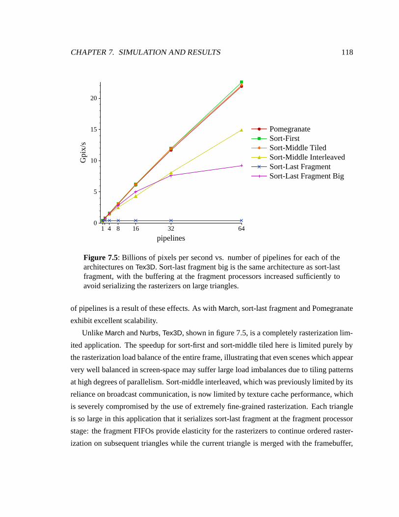
CHAPTER 7. SIMULATION AND RESULTS 118
1 4 8 16 32 64
pipelines
0
5
10
15
20
Gpi
x/s
PomegranateSort-FirstSort-Middle TiledSort-Middle InterleavedSort-Last FragmentSort-Last Fragment Big
Figure 7.5: Billions of pixels per second vs. number of pipelines for each of thearchitectures on Tex3D. Sort-last fragment big is the same architecture as sort-lastfragment, with the buffering at the fragment processors increased sufficiently toavoid serializing the rasterizers on large triangles.
of pipelines is a result of these effects. As with March, sort-last fragment and Pomegranate
exhibit excellent scalability.
Unlike March and Nurbs, Tex3D, shown in figure 7.5, is a completely rasterization lim-
ited application. The speedup for sort-first and sort-middle tiled here is limited purely by
the rasterization load balance of the entire frame, illustrating that even scenes which appear
very well balanced in screen-space may suffer large load imbalances due to tiling patterns
at high degrees of parallelism. Sort-middle interleaved, which was previously limited by its
reliance on broadcast communication, is now limited by texture cache performance, which
is severely compromised by the use of extremely fine-grained rasterization. Each triangle
is so large in this application that it serializes sort-last fragment at the fragment processor
stage: the fragment FIFOs provide elasticity for the rasterizers to continue ordered raster-
ization on subsequent triangles while the current triangle is merged with the framebuffer,
CHAPTER 7. SIMULATION AND RESULTS 119
but when a single large triangle fills up the entire FIFO this elasticity is lost and the raster-
izers are serialized. If we greatly increase the buffering at the fragment processors, shown
by the “sort-last fragment big” curve, so that sort-last fragment is no longer serialized by
the large primitives, the fundamental problem with sort-last fragment is exposed: imbal-
ances in triangle size cause load imbalances across the rasterizers. In Tex3D at 64 pipelines,
the worst rasterizer has almost twice the work of an average rasterizer. Many applications
(e.g. architectural walkthroughs) have a few very large polygons and exhibit much more
severe imbalance in rasterization work than the relatively innocuous Tex3D. Pomegranate
addresses this fundamental problem by load-balancing both the number of triangles and the
number of fragments across the rasterizers, and exhibits excellent scalability on Tex3D.
Chapter 8
Discussion
Pomegranate was designed to support an immediate-mode parallel graphics interface and
uses high-speed point-to-point communication to load-balance work across its pipelines.
Our results have demonstrated the quantitative impact of these choices, and we will now
revisit their qualitative benefits and costs. We also discuss the consistency model Pome-
granate provides, which specifies how the commands of the various graphics contexts may
be interleaved.
While the architecture we have developed is complete, Pomegranate presents interest-
ing areas for further study. We consider possible future work in shared state management,
automatic parallelization, and a revision of the Pomegranate architecture.
8.1 OpenGL and the Parallel API
The decision to support OpenGL, a strict serial API, has proven somewhat complicated
to implement, but has not resulted in a performance impact. In fact, Nurbs, which to-
tally orders the submission of its work across all contexts, achieves almost perfectly linear
speedup, despite its very strong ordering constraints. The expense of supporting ordering
is FIFOs which allow the various pipeline stages to execute commands in application order.
While it may be necessary for the application programmer to choose an appropriate
granularity of parallelism, particularly in a strongly ordered scene, it is not required that
the application balance fragment work, only primitive work. This is a desirable feature, as,
120
CHAPTER 8. DISCUSSION 121
in general, application programmers have little knowledge of the amount of fragment work
that will be generated by a primitive, but they are well aware of the number of primitives
being submitted.
8.2 Communication
Pomegranate uses a network to interconnect all the pipeline stages. This approach to inter-
connecting a graphics system has become much more practical recently due to the advent
of high-speed point-to-point signaling, which reduces the cost of providing the multiple
high bandwidth links necessary in such a network. Nonetheless, we expect the cost of the
network to dominate the cost of implementing an architecture like Pomegranate.
Pomegranate achieves its high scalability only when it is able to use the network as a
point-to-point communication mechanism. Every time broadcast communication is per-
formed, scalability will be lost. However, some commands must be broadcast. Commands
that modify the state of a particular context (e.g. glBlendFunc) must be broadcast to all
of the units using that state. The command distribution could potentially be implemented
lazily, but is still fundamentally a broadcast communication, which will impose a scala-
bility limit. Most high performance applications already try to minimize the frequency of
state changes to maximize performance. It remains to be seen how the potentially greater
cost of state changes in Pomegranate would impact its scalability.
8.3 Consistency Model
Igehy, Stoll and Hanrahan introduced the notion of a consistency model for parallel graph-
ics, as a way to describe the possible interleaving of the fragments of multiple primitives
at the framebuffer [Igehy et al., 1998b]. Their discussion pertained to systems with a par-
allel interface, although if we relax the ordered semantics of the interface, by choice or by
necessity, the same issues arise in any graphics architecture.
If we have a parallel graphics system, then the initial serial command stream from
the application will be processed with some degree of parallelism internally before being
committed to the framebuffer, which may itself be parallel. If ordering is not maintained
CHAPTER 8. DISCUSSION 122
within the system, then any point in the system where parallel computations are merged
has an implied consistency model. We consider the two extreme models proposed by
Igehy et al. In the first model, command-sequential consistency, entire commands (i.e.
primitives) are considered atomic, and the hardware will interleave their execution. In
the second model, fragment-sequential consistency, the only atomic operation is a frame-
buffer read-modify-write update. Without fragment sequential consistency, conventional
operations such as depth compositing will not operate properly, because the compositing
of one fragment may be interposed in the read-modify-write cycle of another fragment
at the same screen location, leading to incorrect operation. Often systems which provide
command-sequential consistency do so at a granularity greater than a single command. For
example, the granularity of parallel work could be several primitives, in which case the
resulting consistency model is “several-command-sequential consistency”. However, be-
cause the interleaving may happen on any arbitrary command boundary, this model is still
just command-sequentially consistent.
If we introduce the parallel API, then even a graphics system with ordered semantics
per context will still have a sequential consistency model which describes how the differ-
ent contexts may be interleaved. Systems such as Argus and Pomegranate rely on a central
scheduler to choose the interleaving of the various contexts, and then communicate that
ordering throughout the system, which results in command-sequential consistency. Par-
allel WireGL takes a different approach, and chooses an ordering independently on each
rendering server, with the result that primitives which overlap the partitions of different
rendering nodes may be interleaved differently on the two servers. Thus WireGL pro-
vides fragment-sequential consistency. The authors of the parallel WireGL system suggest
that any application which generates deterministic images, either through depth-buffering
or through expressing a total order with the parallel API, will operate correctly with just
fragment-sequential consistency.
CHAPTER 8. DISCUSSION 123
8.4 Shared State Management
One of the driving forces behind Pomegranate was to provide full support for ordered se-
mantics, including inter-context ordering constraints expressed via the parallel API. Or-
dered semantics require that operations occur, or appear to occur, in the order specified.
We have extensively described how we order the operations of a single graphics context. In
most cases, computations for a single context may be performed independently of any other
contexts, as the operations are not based on shared state. For example, the transformation
of vertices by the geometry processor depends only on the particular graphics context (ma-
trices, etc.). The exception to this rule is operations on shared state. The most visible piece
of the shared state is the framebuffer, and we have already described how we support the
ordering of the various graphics contexts operations upon it.
There are two other kinds of state that may be shared: texture objects and display lists.
The idea of sharing texture and display list state is already present in GLX and wgl, the
X11 and Microsoft Windows mechanisms for dealing with OpenGL contexts. Both of
these interfaces allow a context to be specified to share display lists and texture objects
with another context. The sharing is transitive, and thus multiple contexts may all share the
same set of texture objects and display lists. The current Pomegranate architecture supports
the sharing of texture objects between multiple contexts, in addition to the use of shared
texture memory.1
8.4.1 Texture Objects
Shared texture objects (and display lists) introduce the complication that they may be cre-
ated, modified or destroyed by one context while other context is using them. The potential
for simultaneous modification introduces a new semantic issue. For example, if a context
updates a texture object, when should those changes be visible? Certainly the modifica-
tions, as well as creation and deletion of shared objects, must be ordered by the parallel
API. In Pomegranate, individual texture updates are made atomic, using the BarrierR
1The meaning of “shared” is unfortunately overloaded here. Until this section, shared texture specificallyreferred to remote reads and writes of memory over a network, as opposed to its replication. Now sharedhas the additional meaning of shared between contexts – thus multiple contexts are sharing the same textureobject. In fact, the two meanings of sharing are completely independent.
CHAPTER 8. DISCUSSION 124
mechanism discussed in section 6.1.1, to provide the correct API semantics for a serial
application. But specifying the complete mipmap hierarchy of a texture requires multiple
texture updates, during which the texture may be in an invalid state. What are the correct
semantics if another context is using such a texture object? One reasonable possibility is to
specify that the semantics are undefined. As the programmer did not order the operations
on the shared object, it apparently would have been equally reasonable for the pre-mutation
or post-mutation value of the object to be used. Would the value of the texture object during
mutation be reasonable to use?
In our current implementation, the state describing texture objects (their filtering modes,
how the texture is repeated, etc.) is maintained by the device driver. When a context
binds a texture object, commands are embedded in the command stream to update the
texture processor context. Contexts that share texture objects use a shared namespace for
the texture object state, thereby observing each other’s changes. The difficulty arises when
one context modifies a texture object that a second context is currently using. Because the
device driver maintains the state, it does not respect any ordering constraints between the
graphics contexts. Moreover, the second context has no reason to notice that the texture
object has been modified, and may continue using old texture object state. We see two
possible solutions to these problems.
Our first solution is to delegate processing of commands that deal with texture objects
to the submit threads. Thus these commands could be processed in an order guaranteed to
be consistent with the parallel API. In this case, each submit thread would have to check the
validity of its currently bound texture object, most likely every time it resolves a parallel
API command, and update its context’s configuration in the texture processor if appropriate.
This has the advantage that texture object management is still virtualized, and avoids the
complexity of implementing it in hardware. The disadvantage of this scheme is its uncertain
complexity, and semantics which are vague at best.
Our second solution is to push the management of shared texture objects all the way into
the hardware, and make it the responsibility of the texture processors. This has the marked
advantage of completely ordering texture commands and providing very clear semantics. It
has the potentially large disadvantage of exposing a virtualization problem to the hardware.
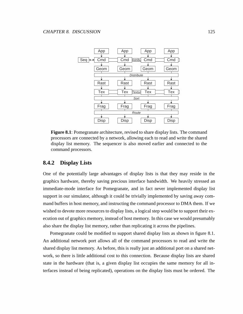
CHAPTER 8. DISCUSSION 125
Distribute
Texture
Seq
Geom
Rast
Frag
Cmd
Disp
Tex
Geom
Rast
Frag
Cmd
Disp
Tex
Geom
Rast
Frag
Cmd
Disp
Tex
Geom
Rast
Frag
Cmd
Disp
Tex
App App App App
Route
Sort
Distribute
Figure 8.1: Pomegranate architecture, revised to share display lists. The commandprocessors are connected by a network, allowing each to read and write the shareddisplay list memory. The sequencer is also moved earlier and connected to thecommand processors.
8.4.2 Display Lists
One of the potentially large advantages of display lists is that they may reside in the
graphics hardware, thereby saving precious interface bandwidth. We heavily stressed an
immediate-mode interface for Pomegranate, and in fact never implemented display list
support in our simulator, although it could be trivially implemented by saving away com-
mand buffers in host memory, and instructing the command processor to DMA them. If we
wished to devote more resources to display lists, a logical step would be to support their ex-
ecution out of graphics memory, instead of host memory. In this case we would presumably
also share the display list memory, rather than replicating it across the pipelines.
Pomegranate could be modified to support shared display lists as shown in figure 8.1.
An additional network port allows all of the command processors to read and write the
shared display list memory. As before, this is really just an additional port on a shared net-
work, so there is little additional cost to this connection. Because display lists are shared
state in the hardware (that is, a given display list occupies the same memory for all in-
terfaces instead of being replicated), operations on the display lists must be ordered. The
CHAPTER 8. DISCUSSION 126
sequencer is therefore connected to the command processors, and the partial order spec-
ified by the submit threads is immediately resolved. It is still advantageous to defer the
determination of a total order to the hardware, as it means the submit threads only have to
communicate between each other to resolve the parallel API, rather than on every block of
application work. Deferring determination of a total order to the hardware also allows for
differences in the speed of execution of the geometry processors, due to differing command
streams. Although we have not measured the effects of placing Pomegranate’s sequencer
at the command processor, we expect that it would perform comparably to the current ar-
chitecture.
8.4.3 Virtual Memory
Texture objects and display lists are largely unbounded in size and number. Both objects
are referred to by integer names, allowing, at least in theory, millions of them to be defined.
Each individual object may additionally be quite large. To deal with the resulting potential
problem of storage, we would like to virtualize texture objects and display lists.
Virtualization is readily dealt with in a conventional graphics architecture with a serial
interface. Because only a single graphics context may be executing in the hardware at any
point in time, it may have free reign to use the hardware resources as it sees fit, including
paging display lists and texture objects out of the memory system to make space for other
objects. When a different context is granted the hardware, either through programmer
action or operating system intervention, the device driver can then restore the new context’s
display list and texture object state as necessary.
In an architecture with a parallel interface, such as Pomegranate, multiple contexts
may be simultaneously creating, modifying and deleting objects. Thus, what had been a
straightforward single-threaded memory management problem, becomes a parallel mem-
ory management problem. Pomegranate simplifies this problem somewhat by insuring that
the are no deadlock issues in the hardware – the submit thread mechanism insures that
work submitted to the hardware is guaranteed to drain. But if it becomes necessary to page
the graphics hardware memory, the paging itself must be correctly serialized, to insure that
memory in use (i.e. currently bound textures, executing display lists) is not paged out.
CHAPTER 8. DISCUSSION 127
Presumably work on multiprocessor virtual memory management would be relevant to this
problem.
One interesting way to address the difficulties of virtualizing the graphics memory is to
provide hardware support for virtual memory, so that the graphics memory may be demand-
paged. While not removing the need for a parallel memory management scheme (to sup-
port multiple simultaneous contexts creating and destroying textures and display lists), this
would neatly solve the difficult problem of paging potentially in-use state in and out of the
graphics system. If the graphics system memory is virtual, then the host computer’s virtual
memory can be used as its backing store. When a graphics page fault occurs, the device
driver is notified and arranges for the transfer of the appropriate page of memory into the
graphics system.
8.5 Automatic Parallelization
When designing Pomegranate, we focused our energies on providing a parallel immediate-
mode interface to the graphics hardware, because for applications with dynamic data it may
be the only way to provide adequate input bandwidth. Without a parallel interface, such an
application may not be able to effectively use more than a single graphics pipeline, unless
the application is rasterization limited. However, for applications that can use interfaces
which reduce the application command bandwidth into the hardware, it would be desirable
if a serial application could effectively utilize multiple pipelines. One attractive solution
is to put support for the parallel API into a scene graph library, such as IRIS Performer
or Java 3D. Thus any application which uses these libraries could use the parallel API
automatically, which little or no programmer effort. Another interesting possibility, with
possibly wider applicability, is to automatically parallelize the serial command stream of
an application.
A simple way to parallelize a serial command stream is to allocate multiple hardware
contexts to the single graphics context, and then distribute the application’s commands
around the contexts, submitting some of the commands through each context. Two issues
must be addressed. First, commands that configure the context (glBlendFunc, glColor,
etc.) must be broadcast, because OpenGL has a stateful interface, and second, the ordered
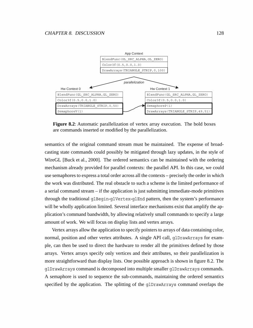
CHAPTER 8. DISCUSSION 128
DrawArrays(TRIANGLE_STRIP,0,100)
parallelization
Color3f(0.5,0.0,1.0)
BlendFunc(GL_SRC_ALPHA,GL_ZERO)
DrawArrays(TRIANGLE_STRIP,0,50)
Color3f(0.5,0.0,1.0)
BlendFunc(GL_SRC_ALPHA,GL_ZERO)
DrawArrays(TRIANGLE_STRIP,49,51)
Color3f(0.5,0.0,1.0)
BlendFunc(GL_SRC_ALPHA,GL_ZERO)
SemaphoreP(1)
SemaphoreV(1)
Hw Context 0 Hw Context 1
App Context
Figure 8.2: Automatic parallelization of vertex array execution. The bold boxesare commands inserted or modified by the parallelization.
semantics of the original command stream must be maintained. The expense of broad-
casting state commands could possibly be mitigated through lazy updates, in the style of
WireGL [Buck et al., 2000]. The ordered semantics can be maintained with the ordering
mechanism already provided for parallel contexts: the parallel API. In this case, we could
use semaphores to express a total order across all the contexts – precisely the order in which
the work was distributed. The real obstacle to such a scheme is the limited performance of
a serial command stream – if the application is just submitting immediate-mode primitives
through the traditional glBegin-glVertex-glEnd pattern, then the system’s performance
will be wholly application limited. Several interface mechanisms exist that amplify the ap-
plication’s command bandwidth, by allowing relatively small commands to specify a large
amount of work. We will focus on display lists and vertex arrays.
Vertex arrays allow the application to specify pointers to arrays of data containing color,
normal, position and other vertex attributes. A single API call, glDrawArrays for exam-
ple, can then be used to direct the hardware to render all the primitives defined by those
arrays. Vertex arrays specify only vertices and their attributes, so their parallelization is
more straightforward than display lists. One possible approach is shown in figure 8.2. The
glDrawArrays command is decomposed into multiple smaller glDrawArrays commands.
A semaphore is used to sequence the sub-commands, maintaining the ordered semantics
specified by the application. The splitting of the glDrawArrays command overlaps the
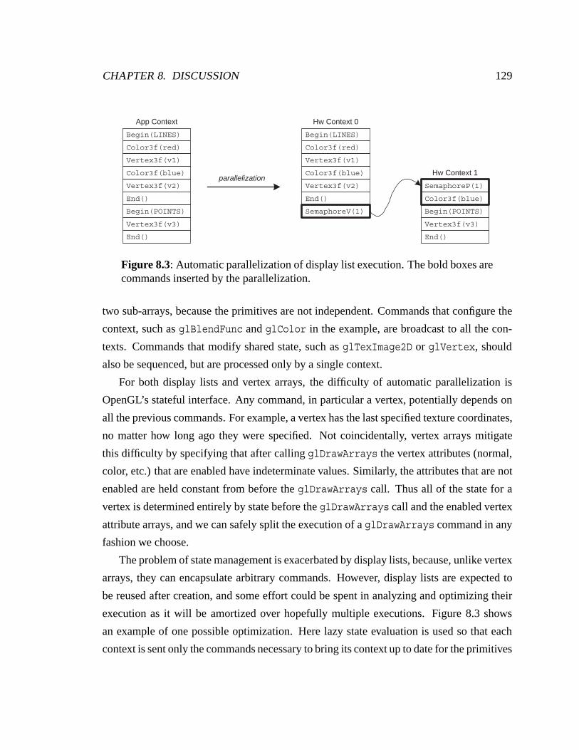
CHAPTER 8. DISCUSSION 129
parallelization
Color3f(red)
Begin(LINES)
Vertex3f(v1)
Color3f(blue)
End()
Vertex3f(v2)
Begin(POINTS)
Vertex3f(v3)
End()
Color3f(red)
Begin(LINES)
Vertex3f(v1)
Color3f(blue)
End()
Vertex3f(v2)
Begin(POINTS)
Vertex3f(v3)
End()
SemaphoreP(1)
Color3f(blue)
App Context Hw Context 0
Hw Context 1
SemaphoreV(1)
Figure 8.3: Automatic parallelization of display list execution. The bold boxes arecommands inserted by the parallelization.
two sub-arrays, because the primitives are not independent. Commands that configure the
context, such as glBlendFunc and glColor in the example, are broadcast to all the con-
texts. Commands that modify shared state, such as glTexImage2D or glVertex, should
also be sequenced, but are processed only by a single context.
For both display lists and vertex arrays, the difficulty of automatic parallelization is
OpenGL’s stateful interface. Any command, in particular a vertex, potentially depends on
all the previous commands. For example, a vertex has the last specified texture coordinates,
no matter how long ago they were specified. Not coincidentally, vertex arrays mitigate
this difficulty by specifying that after calling glDrawArrays the vertex attributes (normal,
color, etc.) that are enabled have indeterminate values. Similarly, the attributes that are not
enabled are held constant from before the glDrawArrays call. Thus all of the state for a
vertex is determined entirely by state before the glDrawArrays call and the enabled vertex
attribute arrays, and we can safely split the execution of a glDrawArrays command in any
fashion we choose.
The problem of state management is exacerbated by display lists, because, unlike vertex
arrays, they can encapsulate arbitrary commands. However, display lists are expected to
be reused after creation, and some effort could be spent in analyzing and optimizing their
execution as it will be amortized over hopefully multiple executions. Figure 8.3 shows
an example of one possible optimization. Here lazy state evaluation is used so that each
context is sent only the commands necessary to bring its context up to date for the primitives
CHAPTER 8. DISCUSSION 130
it is assigned to render. Thus the stream of colors, normals, etc. specified for primitives
rendered by other contexts will not be needlessly broadcast. Our example is simpler than
the more general display list case, which can include calls to other display lists, which could
also be parallelized, etc. One possible way to address the added complexity of display lists
calling display list would be to make leaf display lists (those that don’t in turn invoke other
display lists) the basic unit of parallelism. A leaf display list could be factored into two
parts, the list itself, and the list’s effects on the state (current color, etc.). Then one context
would be chosen to execute any particular leaf display list, while all the other contexts only
execute the state differences.
8.6 Pomegranate-2
The current Pomegranate architecture is based in part on the assumption that the geometry
work is application visible, because the amount of geometry work is in fixed proportion to
the kind and number of commands submitted by the application. This is not necessarily
always the case. For example, a display list command can generate a great deal of work
for the hardware, while requiring almost no application work. Granted, the programmer
may be aware of how much work it will require, since he constructed the display list, but
that does not mean he necessarily wishes to specify the parallelization of its execution, or
its distribution across pipelines. Similarly, the use of higher order primitives which are
adaptively tessellated by the hardware, such as Bezier surface patches, may result in input
geometry that creates an amount of work proportional to screen-space area.
These situations, in which the amount of geometry work is not visible to the program-
mer, motivate us to consider schemes in which the geometry processors are decoupled
from the inputs. Such an architecture, which we refer to as Pomegranate-2, could be built
as shown in figure 8.4. Pomegranate-2 introduces an additional stage of communication
between the command processors and geometry processors, allowing each command pro-
cessor to distribute and load-balance its work across all the geometry processors. In the ar-
chitecture shown here, the sequencer is adjacent to the command processors, and geometry
processors receive Execute commands, specifying the sequence in which they should pro-
cess work from the command processors. The disadvantage of this approach is that it does
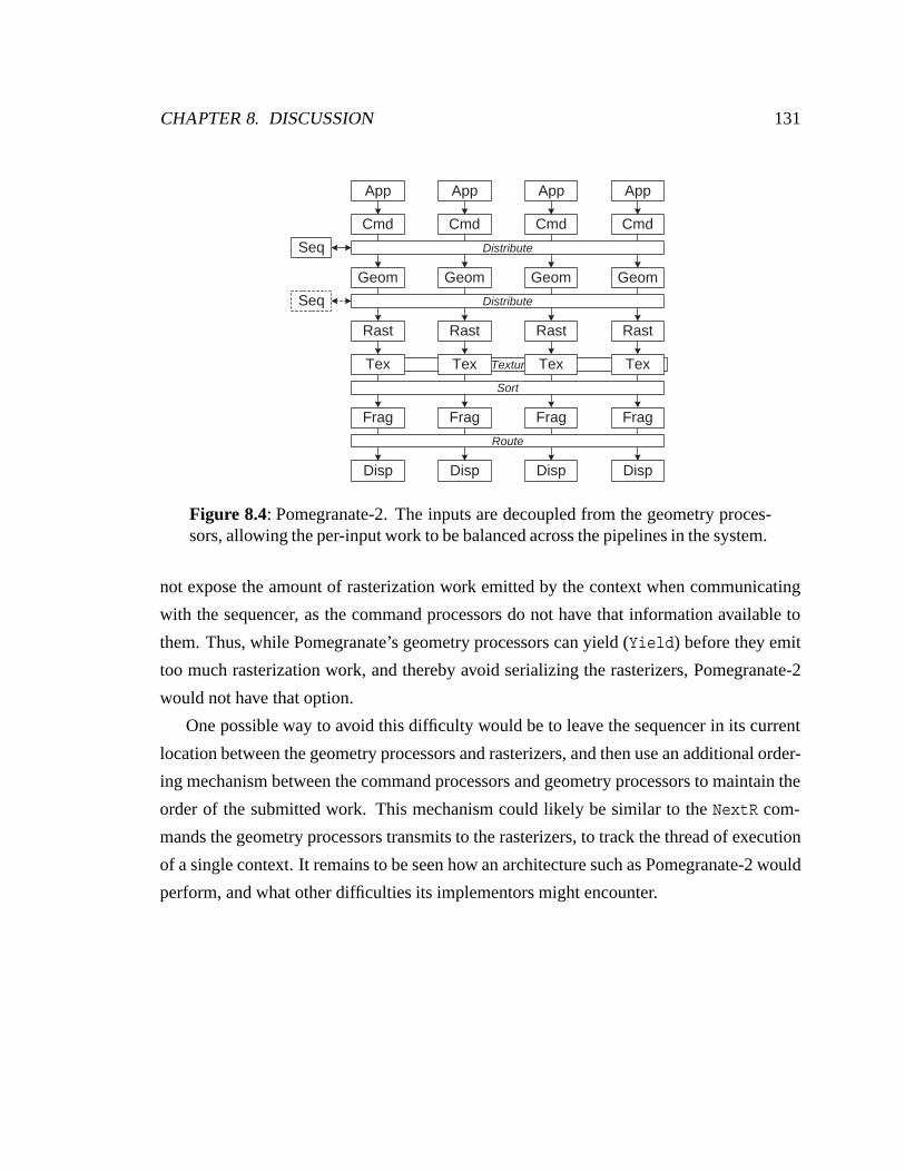
CHAPTER 8. DISCUSSION 131
Texture
Seq
Geom
Rast
Frag
Cmd
Disp
Tex
Geom
Rast
Frag
Cmd
Disp
Tex
Geom
Rast
Frag
Cmd
Disp
Tex
Geom
Rast
Frag
Cmd
Disp
Tex
App App App App
Seq
Route
Sort
Distribute
Distribute
Figure 8.4: Pomegranate-2. The inputs are decoupled from the geometry proces-sors, allowing the per-input work to be balanced across the pipelines in the system.
not expose the amount of rasterization work emitted by the context when communicating
with the sequencer, as the command processors do not have that information available to
them. Thus, while Pomegranate’s geometry processors can yield (Yield) before they emit
too much rasterization work, and thereby avoid serializing the rasterizers, Pomegranate-2
would not have that option.
One possible way to avoid this difficulty would be to leave the sequencer in its current
location between the geometry processors and rasterizers, and then use an additional order-
ing mechanism between the command processors and geometry processors to maintain the
order of the submitted work. This mechanism could likely be similar to the NextR com-
mands the geometry processors transmits to the rasterizers, to track the thread of execution
of a single context. It remains to be seen how an architecture such as Pomegranate-2 would
perform, and what other difficulties its implementors might encounter.
Chapter 9
Conclusions
This thesis has examined parallel graphics architectures from a joint perspective of scala-
bility and communication, and synthesized a new architecture, Pomegranate, optimized for
efficient communication and high scalability.
Parallel graphics architecture is fundamentally a problem in efficiently managing object
and image parallelism, and the transition between them. This transition between object and
image parallelism is the “sort” in parallel graphics architecture, and creates the necessity
for communication in any such architecture. We have made two extensions to the parallel
graphics sorting taxonomy. First, we more carefully distinguish the location of the sort
within the graphics pipeline. This provides a clearer picture of specific architectures, and
also allows us to draw a clearer distinction between architectures which sort fragments, and
those which composite images. Second, we consider more forms of communication than
just the sort. Most parallel graphics architectures also include distribution (object-parallel),
routing (image-parallel) and texture communication. Examining a number of architectures
under this communication-centric taxonomy leads to two broad conclusions for creating a
scalable graphics architecture. First, broadcast communication must be avoided. It requires
a broadcast interconnect, which scales only at high cost, and broadcast computation, which
does not scale at all. Second, image parallelism must be carefully managed. Tiled image
parallelism provides limited available parallelism, and requires a careful balance between
a reduced overlap factor and increasing load imbalance. Moreover, the difficulties of tiled
image parallelism are worsened by strong scene dependencies and temporal effects. In
132
CHAPTER 9. CONCLUSIONS 133
contrast, interleaved image parallelism achieves an excellent load balance, at the cost of
requiring broadcast communication if used any earlier than texture processing.
With a grounding in our observations from this revised parallel graphics taxonomy,
we developed Pomegranate, a new fully scalable graphics architecture. Our observations
led us to a sort-last fragment architecture, which uses interleaved image parallelism for
the fragment processors, and object parallelism for previous stages. In order to provide
Pomegranate with sufficient input bandwidth, we provide a parallel interface to the hard-
ware, allowing multiple graphics contexts to be submitting commands simultaneously over
independent interfaces.
Load-balancing the many object parallel stages of a sort-last fragment architecture
presents a potential stumbling block. In particular, rasterization work is proportional to
primitive area, which is not known a priori. In sort-first and sort-middle architectures this
load-balancing problem is addressed by partitioning the screen across the rasterizers. In a
sort-last fragment architecture another solution must be found. Our solution is to include a
stage of communication after the geometry processors, allowing each geometry processor
to distribute its rasterization work in a load-balanced fashion across the rasterizers. Texture
processing suffers the same load-balancing problems as rasterization, which we address
by coupling rasterization and texture processing, thus load-balancing them together. This
also meets our requirement for a bandwidth-efficient texture system. Good texture caching
behavior can be guaranteed by assigning groups of primitives to rasterizers, while avoid-
ing the need to communicate large untextured fragments or independently load-balance the
texture processing stage.
Our choice of a sort-last fragment architecture for Pomegranate was driven by our de-
sire for a scalable architecture. We have shown that scalability requires that broadcast
communication be avoided. Pomegranate avoids the use of broadcast communication for
the distribution of primitives as well as the sorting of fragments. As a direct consequence,
we can use a scalable point-to-point interconnect within Pomegranate, which has excel-
lent efficiency and scalability. Previous architectures that have stressed communication
efficiency, and the avoidance of broadcast, most notably image composition architectures,
CHAPTER 9. CONCLUSIONS 134
have done so at the expense of supporting ordered execution or an immediate mode inter-
face. Pomegranate demonstrates that through the use of buffering and a lightweight order-
ing mechanism, ordered semantics and an immediate mode interface can be maintained,
while still providing excellent scalability.
While much of our discussion has focused on externally parallel graphics architectures
– those constructed of multiple chips and boards – we expect architectures such as Pome-
granate to be increasingly important for single-chip designs. The increasing complexity
of designing a single chip, which will soon exceed one billion transistors, makes the im-
plementation of a single deep pipeline more and more difficult. Architectures such as
Pomegranate provide a way to construct a single, simpler, graphics pipeline and replicate it
to provide increased performance in an efficient fashion. The availability of enormous on-
chip interconnect bandwidth will make architectures such as Pomegranate not only efficient
at the single-chip level, but extremely practical as well.
Bibliography
[Akeley, 1993] Kurt Akeley. RealityEngine Graphics. In SIGGRAPH 93
Conference Proceedings, pages 109–116, August 1993.
[Boden et al., 1995] Nanette J. Boden, Danny Cohen, Robert E. Felderman,
Alan E. Kulawik, Charles L. Seitz, Jakov N. Seizovic, and
Wen-King Su. Myrinet: A Gigabit-per-second Local Area
Network. IEEE Micro, pages 29–36, February 1995.
[Buck et al., 2000] Ian Buck, Greg Humphreys, and Pat Hanrahan. Tracking
Graphics State for Networked Rendering. In 2000 SIG-
GRAPH / Eurographics Workshop on Graphics Hardware,
pages 87–95, August 2000.
[Bunker and Economy, 1989] M. Bunker and R. Economy. Evolution of GE CIG Sys-
tems. Technical report, General Electric Company, 1989.
[Chen et al., 1998] Milton Chen, Gordon Stoll, Homan Igehy, Kekoa Proud-
foot, and Pat Hanrahan. Models of the Impact of Overlap in
Bucket Rendering. 1998 SIGGRAPH / Eurographics Work-
shop on Graphics Hardware, pages 105–112, August 1998.
[Cook et al., 1987] Robert L. Cook, Loren Carpenter, and Edwin Catmull. The
Reyes Image Rendering Architecture. In SIGGRAPH 87
Conference Proceedings, pages 95–102, July 1987.
[Cox and Hanrahan, 1993] Michael Cox and Pat Hanrahan. Pixel Merging for Object-
Parallel Rendering: a Distributed Snooping Algorithm.
135
BIBLIOGRAPHY 136
Proceedings of the 1993 Symposium on Parallel Rendering,
pages 49–56, October 1993.
[Cox et al., 1998] Michael Cox, Narendra Bhandari, and Michael Shantz.
Multi-Level Texture Caching for 3D Graphics Hardware.
In Proceedings of the 25th Annual Symposium on Computer
Architecture, pages 86–97, June 1998.
[Cunniff, 2000] Ross Cunniff. Visualize fx Graphics Scalable Architecture.
In Proceedings of Eurographics Hardware/SIGGRAPH
Hot3D, pages 29–38, August 2000.
[Dally, 1992] William J. Dally. Virtual–Channel Flow Control. IEEE
Transactions on Parallel and Distributed Systems, pages
194–205, March 1992.
[Deering and Nelson, 1993] Michael F. Deering and Scott R. Nelson. Leo: A System
for Cost Effective 3D Shaded Graphics. In SIGGRAPH 93
Conference Proceedings, pages 101–108, August 1993.
[Deering et al., 1988] Michael Deering, Stephanie Winner, Bic Schediwy, Chris
Duffy, and Neil Hunt. The Triangle Processor and Nor-
mal Vector Shader: A VLSI System for High Performance
Graphics. In SIGGRAPH 88 Conference Proceedings,
pages 21–30, August 1988.
[Duato et al., 1997] Jose Duato, Sudhakar Yalamanchili, and Lionel Ni. In-
terconnection Networks: An Engineering Approach. IEEE
Computer Society Press, 1997.
[Eldridge et al., 2000] Matthew Eldridge, Homan Igehy, and Pat Hanrahan. Pome-
granate: A Fully Scalable Graphics Architecture. In SIG-
GRAPH 00 Conference Proceedings, pages 443–454, July
2000.
BIBLIOGRAPHY 137
[Evans & Sutherland, 1992] Evans & Sutherland. Freedom Series Technical Overview.
Technical report, Evans & Sutherland Computer Corpora-
tion, October 1992.
[Eyles et al., 1997] John Eyles, Steven Molnar, John Poulton, Trey Greer,
Anselmo Lastra, Nick England, and Lee Westover. Pix-
elFlow: The Realization. In 1997 SIGGRAPH / Eurograph-
ics Workshop on Graphics Hardware, pages 57–68, August
1997.
[Foley et al., 1990] James D. Foley, Andries van Dam, Steven K. Feiner, and
John F. Hughes. Computer Graphics: Principles and Prac-
tice. Addison–Wesley, second edition, 1990.
[Fuchs and Johnson, 1979] Henry Fuchs and Brian W. Johnson. An Expandable Multi-
processor Architecture for Video Graphics. In Proceedings
of the 6th ACM-IEEE Symposium on Computer Architec-
ture, pages 58–67, April 1979.
[Fuchs et al., 1989] Henry Fuchs, John Poulton, John Eyles, Trey Greer, Jack
Goldfeather, David Ellsworth, Steve Molnar, Greg Turk,
Brice Tebbs, and Laura Isreal. Pixel-Planes 5: A Hetero-
geneous Multiprocessor Graphics System Using Processor-
Enhanced Memories. In SIGGRAPH 89 Conference Pro-
ceedings, pages 79–88, July 1989.
[Fuchs, 1977] Henry Fuchs. Distributing a Visible Surface Algorithm
Over Multiple Processors. In Proceedings of the ACM An-
nual Conference, pages 449–451, October 1977.
[Hakura and Gupta, 1997] Ziyad S. Hakura and Anoop Gupta. The Design and Anal-
ysis of a Cache Architecture for Texture Mapping. In Pro-
ceedings of the 24th Annual Symposium on Computer Ar-
chitecture, pages 108–119, June 1997.
BIBLIOGRAPHY 138
[Harrell and Fouladi, 1993] Chandlee B. Harrell and Farhad Fouladi. Graphics Render-
ing Architecture for a High Performance Desktop Work-
station. In SIGGRAPH 93 Conference Proceedings, pages
93–100, August 1993.
[Heirich and Moll, 1999] Alan Heirich and Laurent Moll. Scalable Distributed Vi-
sualization Using Off-the-Shelf Components. In Proceed-
ings of the Parallel Visualization and Graphics Symposium
1999, October 1999.
[Humphreys et al., 2000] Greg Humphreys, Ian Buck, Matthew Eldridge, and Pat
Hanrahan. Distributed Rendering for Scalable Displays.
Proceedings of Supercomputing 2000, November 2000.
[Humphreys et al., 2001] Greg Humphreys, Matthew Eldridge, Ian Buck, Matthew
Everett, Gordon Stoll, and Pat Hanrahan. WireGL: A Scal-
able Graphics System for Clusters. SIGGRAPH 01 Confer-
ence Proceedings, July 2001.
[Igehy et al., 1998a] Homan Igehy, Matthew Eldridge, and Kekoa Proudfoot.
Prefetching in a Texture Cache Architecture. 1998 SIG-
GRAPH / Eurographics Workshop on Graphics Hardware,
pages 133–142, August 1998.
[Igehy et al., 1998b] Homan Igehy, Gordon Stoll, and Pat Hanrahan. The Design
of a Parallel Graphics Interface. In SIGGRAPH 98 Confer-
ence Proceedings, pages 141–150, July 1998.
[Igehy et al., 1999] Homan Igehy, Matthew Eldridge, and Pat Hanrahan. Par-
allel Texture Caching. 1999 SIGGRAPH / Eurographics
Workshop on Graphics Hardware, pages 95–106, August
1999.
BIBLIOGRAPHY 139
[Kelley et al., 1992] Michael Kelley, Stephanie Winner, and Kirk Gould. A Scal-
able Hardware Render Accelerator using a Modified Scan-
line Algorithm. In SIGGRAPH 92 Conference Proceedings,
pages 241–248, July 1992.
[Kelley et al., 1994] Michael Kelley, Kirk Gould, Brent Pease, Stephanie Win-
ner, and Alex Yen. Hardware Accelerated Rendering of
CSG and Transparency. In SIGGRAPH 94 Conference Pro-
ceedings, pages 177–184, July 1994.
[Kubota Pacific, 1993] Kubota Pacific. Denali Technical Overview. Technical re-
port, Kubota Pacific Computer Inc., March 1993.
[Lorensen and Cline, 1987] William E. Lorensen and Harvey E. Cline. Marching
Cubes: A High Resolution 3D Surface Construction Al-
gorithm. Computer Graphics (SIGGRAPH 87 Conference
Proceedings), pages 163–169, July 1987.
[Ma et al., 1994] Kwan-Liu Ma, James S. Painter, Charles D. Hansen, and
Michael F. Krogh. Parallel Volume Rendering Using
Binary-Swap Compositing. IEEE Computer Graphics and
Applications, pages 59–68, July 1994.
[McCormack et al., 1998] Joel McCormack, Robert McNamara, Christopher Gianos,
Larry Seiler, Norman P. Jouppi, and Ken Correll. Neon:
A Single-Chip 3D Workstation Graphics Accelerator. 1998
SIGGRAPH / Eurographics Workshop on Graphics Hard-
ware, pages 123–132, August 1998.
[Moll et al., 1999] Laurent Moll, Alan Heirich, and Mark Shand. Sepia: Scal-
able 3D Compositing Using PCI Pamette. In Proceedings
of the IEEE Symposium on Field Programmable Custom
Computing Machines 1999, pages 146–155, April 1999.
BIBLIOGRAPHY 140
[Molnar and Fuchs, 1990] Steven Molnar and Henry Fuchs. Advanced Raster Graph-
ics Architecture, chapter 18, pages 899–900. In Foley et al.
[1990], second edition, 1990.
[Molnar et al., 1992] Steven Molnar, John Eyles, and John Poulton. PixelFlow:
High-Speed Rendering Using Image Composition. In SIG-
GRAPH 92 Conference Proceedings, pages 231–240, July
1992.
[Molnar et al., 1994] Steven Molnar, Michael Cox, David Ellsworth, and Henry
Fuchs. A Sorting Classification of Parallel Rendering.
IEEE Computer Graphics and Applications, pages 23–32,
July 1994.
[Molnar, 1995] Steven Molnar. The PixelFlow Texture and Image Subsys-
tem. In 1995 Eurographics Workshop on Graphics Hard-
ware, pages 3–13, August 1995.
[Montrym et al., 1997] John S. Montrym, Daniel R. Baum, David L. Dignam,
and Christopher J. Migdal. InfiniteReality: A Real-Time
Graphics System. SIGGRAPH 97 Conference Proceedings,
pages 293–302, August 1997.
[Mueller, 1995] Carl Mueller. The Sort-First Rendering Architecture for
High-Performance Graphics. Proceedings of the 1995 Sym-
posium on Interactive 3D Graphics, pages 75–84, April
1995.
[Mueller, 1997] Carl Mueller. Hierarchical Graphics Databases in Sort-
First. Proceedings of the 1997 Symposium on Parallel Ren-
dering, pages 49–57, October 1997.
[Nishimura and Kunii, 1996] Satoshi Nishimura and Tosiyasu L. Kunii. VC-1: A Scal-
able Graphics Computer with Virtual Local Frame Buffers.
BIBLIOGRAPHY 141
In SIGGRAPH 96 Conference Proceedings, pages 365–
372, August 1996.
[OpenGL Architecture Review Board, 1997] OpenGL Architecture Review Board.
OpenGL Reference Manual: the Official Reference
Document to OpenGL, Version 1.1. Addison–Wesley,
1997.
[Owens et al., 2000] John D. Owens, William J. Dally, Ujval J. Kapasi, Scott
Rixner, Peter Mattson, and Ben Mowery. Polygon Render-
ing on a Stream Architecture. In 2000 SIGGRAPH / Euro-
graphics Workshop on Graphics Hardware, pages 23–32,
August 2000.
[Parke, 1980] Frederic I. Parke. Simulation and Expected Performance
Analysis of Multiple Processor Z-Buffer Systems. In SIG-
GRAPH 80 Conference Proceedings, pages 48–56, July
1980.
[Potmesil and Hoffert, 1989] Michael Potmesil and Eric M. Hoffert. The Pixel Machine:
A Parallel Image Computer. In SIGGRAPH 89 Conference
Proceedings, pages 69–78, July 1989.
[PowerVR Technologies, 2001] PowerVR Technologies. PowerVR White Papers,
2001. http://www.powervr.com/WhitePapers/
WhitePapers.htm.
[Rohlf and Helman, 1994] John Rohlf and James Helman. IRIS Performer: A High
Performance Multiprocessing Toolkit for Real-Time 3D
Graphics. In SIGGRAPH 94 Conference Proceedings,
pages 381–394, July 1994.
BIBLIOGRAPHY 142
[Samanta et al., 1999] Rudrajit Samanta, Jiannan Zheng, Thomas Funkhouser,
Kai Li, and Jaswinder Pal Singh. Load Balancing for Multi-
Projector Rendering Systems. 1999 SIGGRAPH / Euro-
graphics Workshop on Graphics Hardware, pages 107–
116, August 1999.
[Samanta et al., 2000] Rudrajit Samanta, Thomas Funkhouser, Kai Li, and
Jaswinder Pal Singh. Hybrid Sort-First and Sort-Last Par-
allel Rendering with a Cluster of PCs. 2000 SIGGRAPH /
Eurographics Workshop on Graphics Hardware, pages 97–
108, August 2000.
[Segal and Akeley, 1999] Mark Segal and Kurt Akeley. The OpenGL Graphics Sys-
tem: A Specification (Version 1.2.1). 1999. ftp://ftp.
sgi.com/opengl/doc/opengl1.2/.
[Silicon Graphics, c 1990a] Silicon Graphics. POWER Series Technical Report. Tech-
nical report, Silicon Graphics, Inc., c. 1990. http://www.
reputable.com/˜skywriter/pstech/.
[Silicon Graphics, c 1990b] Silicon Graphics. SkyWriter Technical Report.
Technical report, Silicon Graphics, Inc., c. 1990.
http://www.reputable.com/˜skywriter/skywriter/
techreport/.
[Stoll et al., 2001] Gordon Stoll, Matthew Eldridge, Dan Patterson, Art Webb,
Steven Berman, Richard Levy, Chris Caywood, Milton
Taveira, Stephen Hunt, and Pat Hanrahan. Lightning-2:
A High-Performance Display Subsystem for PC Clusters.
SIGGRAPH 01 Conference Proceedings, July 2001.
[Torborg and Kajiya, 1996] Jay Torborg and James T. Kajiya. Talisman: Commodity
Realtime 3D Graphics for the PC. In SIGGRAPH 96 Con-
ference Proceedings, pages 353–363, August 1996.
BIBLIOGRAPHY 143
[Vartanian et al., 1998] Alexis Vartanian, Jean-Luc Bechennec, and Nathalie
Drach-Temam. Evaluation of High Performance Multi-
cache Parallel Texture Mapping. In Proceedings of the
ACM International Conference on Supercomputing 1998,
pages 289–296, July 1998.
[Vartanian et al., 2000] Alexis Vartanian, Jean-Luc Bechennec, and Nathalie
Drach-Temam. The Best Distribution for a Parallel
OpenGL 3D Engine with Texture Caches. In Proceedings
of the 6th International Symposium on High Performance
Computer Architecture, pages 399–408, January 2000.
[Voorhies et al., 1988] Douglas Voorhies, David Kirk, and Olin Lathrop. Vir-
tual Graphics. In SIGGRAPH 88 Conference Proceedings,
pages 247–253, August 1988.