Embed Size (px)
Citation preview
Designing geared 3D twisty puzzles(on the example of Gear Pyraminx)© Timur Evbatyrov, Jan 2012
Introduction
In this tutorial I’ll demonstrate you my own method of designing geared 3D twisty puzzles on the example of Gear Pyraminx designed in SolidWorks (hereinafter SW). I must say it beforehand that this is not a tutorial for SW. So, if I say, “let’s make a loft surface from this curve to the center point”, I assume that you are aware of how to do it and where to find this feature in SW. Best, if you already have some experience of designing twisty puzzles. The purpose of this tutorial is only to show you how gears work and how to draw them in SW or other CAD programs.
§1. Plain gears.
Understanding the basic principles of gears theory is easier with plain (2D) gears. You can find many articles on this topic in the web, but they seem to contain too many definitions and formulae. I’ll try to limit myself with the only notions that we need in designing geared twisty puzzles and make it as simply as possible.
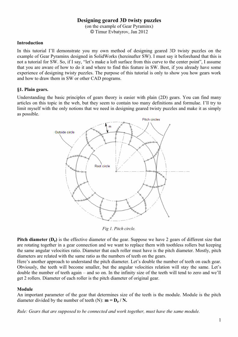
Fig 1. Pitch circle.
Pitch diameter (Dp) is the effective diameter of the gear. Suppose we have 2 gears of different size that are rotating together in a gear connection and we want to replace them with toothless rollers but keeping the same angular velocities ratio. Diameter that each roller must have is the pitch diameter. Mostly, pitch diameters are related with the same ratio as the numbers of teeth on the gears.Here’s another approach to understand the pitch diameter. Let’s double the number of teeth on each gear. Obviously, the teeth will become smaller, but the angular velocities relation will stay the same. Let’s double the number of teeth again – and so on. In the infinity size of the teeth will tend to zero and we’ll get 2 rollers. Diameter of each roller is the pitch diameter of original gear.
ModuleAn important parameter of the gear that determines size of the teeth is the module. Module is the pitch diameter divided by the number of teeth (N): m = Dp / N.
Rule: Gears that are supposed to be connected and work together, must have the same module.
1
Outside and root diameters (Do, Dr) are the diameters of tops and bottoms of the gear teeth. In ideal universe they would be equidistant from the pitch diameter (with module as the distance), but in practice the bottom diameter is made a little smaller to avoid contact between bottoms and tops of contacting gears:
Do = Dp + m,Dr = Dp – 1.25m.
Base circle
To understand what base circle is, we need to understand what curve lies behind a tooth profile. Of course, different curves may be used for tooth profiles, but the most widespread approach is to use an involute (another word is evolvent) of a circle. Involute is a curve that is drawn by an end of a thread which is winded (or unwinded) around some circle. Actually involute is an infinite spiral, but a very short part of it is used in a tooth profile – only the part that lies between outside and root circles. Base diameter Db of a gear is the diameter of the circle, from which the thread is being unwinded to make a tooth profile.
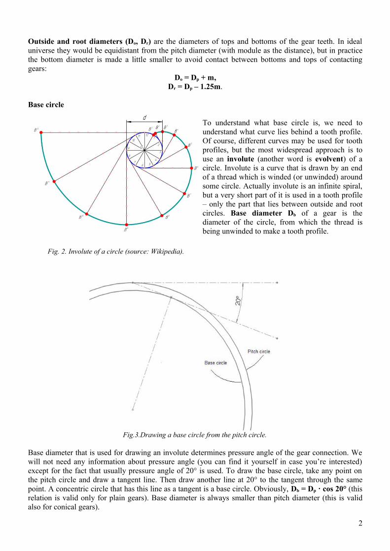
Fig. 2. Involute of a circle (source: Wikipedia).
Fig.3.Drawing a base circle from the pitch circle.
Base diameter that is used for drawing an involute determines pressure angle of the gear connection. We will not need any information about pressure angle (you can find it yourself in case you’re interested) except for the fact that usually pressure angle of 20° is used. To draw the base circle, take any point on the pitch circle and draw a tangent line. Then draw another line at 20° to the tangent through the same point. A concentric circle that has this line as a tangent is a base circle. Obviously, Db = Dp · cos 20° (this relation is valid only for plain gears). Base diameter is always smaller than pitch diameter (this is valid also for conical gears).
2
If there are many teeth on the gear, they are small and completely lie outside of the base circle. But with smaller number of teeth root diameter is smaller than base diameter (you can calculate from the previous definitions that this happens when a plain gear has less than 18 teeth). Because an involute does not exist inside the base circle, in such case we are kind of unlucky as we don’t know how to draw this inner part of tooth profile. This problem is solved so: at first draw an involute part that you can draw (between base circle and outside circle) and continue the curve inwards by a visual feeling until you reach the root circle.
§2. Introduction to 3D gears.
Gears that we have been talking about in the previous section are plain 2D gears whose rotation axes are all parallel to each other. In twisty puzzles (well, in most twisty puzzles), all rotation axes go to the center of the puzzle so they are not parallel. Gears that are supposed to work with non-parallel axes must be conical. They are drawn on a sphere and projected towards the center.
As I already said, there’s plenty of information in the web about plain gears but I found almost nothing about principles of designing conical gears so I had to derive them myself. Actually they are the same as with plain gears, but there are some very significant and interesting differences.
§3. Sketch of the puzzle.
After we have some idea of a gear puzzle in the head, at first we draw a sketch of a geared layer (usually it’s an external layer, while non-geared mechanism is placed inside). At this step we do not need to have gears and can use conical rollers instead. As you remember, conical rollers represent pitch circles of future gears and they have the same angular velocities ratio, so they are almost equivalent to gears. To draw the rollers, you may cut them from the sphere with conical cutting surfaces.
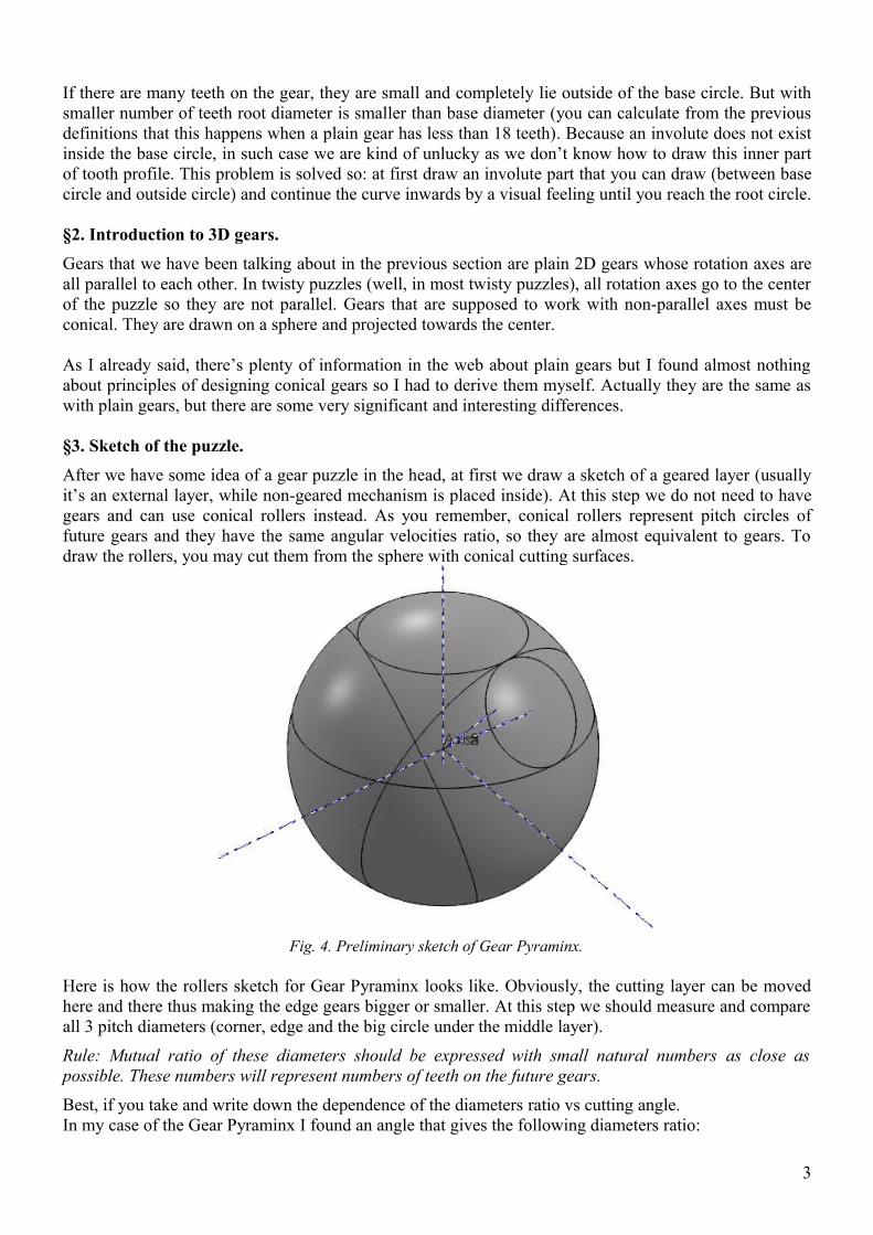
Fig. 4. Preliminary sketch of Gear Pyraminx.
Here is how the rollers sketch for Gear Pyraminx looks like. Obviously, the cutting layer can be moved here and there thus making the edge gears bigger or smaller. At this step we should measure and compare all 3 pitch diameters (corner, edge and the big circle under the middle layer).
Rule: Mutual ratio of these diameters should be expressed with small natural numbers as close as possible. These numbers will represent numbers of teeth on the future gears.
Best, if you take and write down the dependence of the diameters ratio vs cutting angle. In my case of the Gear Pyraminx I found an angle that gives the following diameters ratio:
3
11.95 mm : 17.92 mm: 31.72 mm = 1 : 1.50 : 2.654, or
6 : 9 : 15.92.
That leads to the ratio 6 : 9 : 15 that is now used in the Gear Pyraminx. Is that very bad that 15 is taken instead of 15.92? It's not. Gears can actually forget much - I just increased space between teeth by 6% and drew 15 teeth where there should be 16.
Important thing of this ratio is that 9 and 15 divide by 3 – this is necessary for rotational symmetry of the puzzle. And it’s good that the edge gear has 6 teeth – first, because it divides by 2 (so the edge gear can be flipped), second, because edge and corner teeth numbers both divide by 3. This simplifies the puzzle and makes it definitely easier to solve (if we had 7 and 9 teeth on the edge and the corner, I don't think it would be pleasant to solve the puzzle). I personally think that this ratio 6:9:15 is ideal for Gear Pyraminx and better ratio just does not exist.
Now when we know the number of teeth, we can calculate the module by dividing the pitch diameters by 6, 9 and 15. We'll get 1.99 mm, 1.99 mm and 2.11 mm. Because 15 is kind off a miss, we take m = 1.99 mm.
§4. Drawing a gear on the sphere.
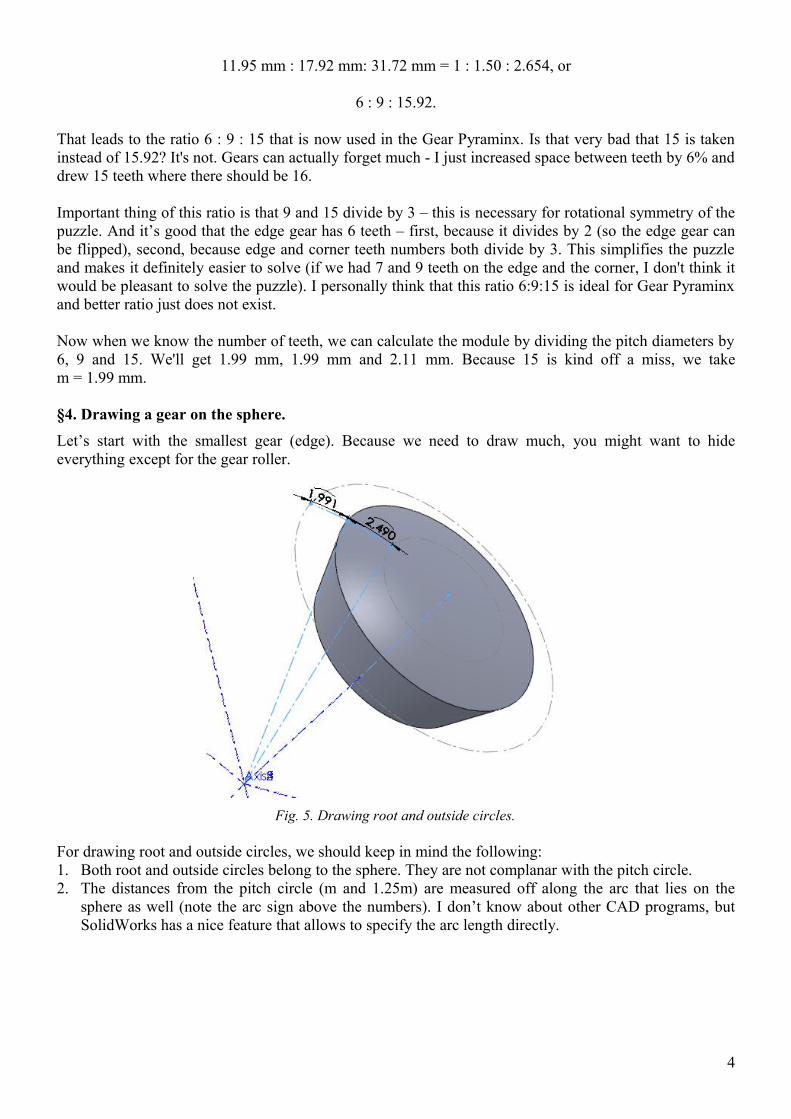
Let’s start with the smallest gear (edge). Because we need to draw much, you might want to hide everything except for the gear roller.
Fig. 5. Drawing root and outside circles.
For drawing root and outside circles, we should keep in mind the following:1. Both root and outside circles belong to the sphere. They are not complanar with the pitch circle.2. The distances from the pitch circle (m and 1.25m) are measured off along the arc that lies on the
sphere as well (note the arc sign above the numbers). I don’t know about other CAD programs, but SolidWorks has a nice feature that allows to specify the arc length directly.
4
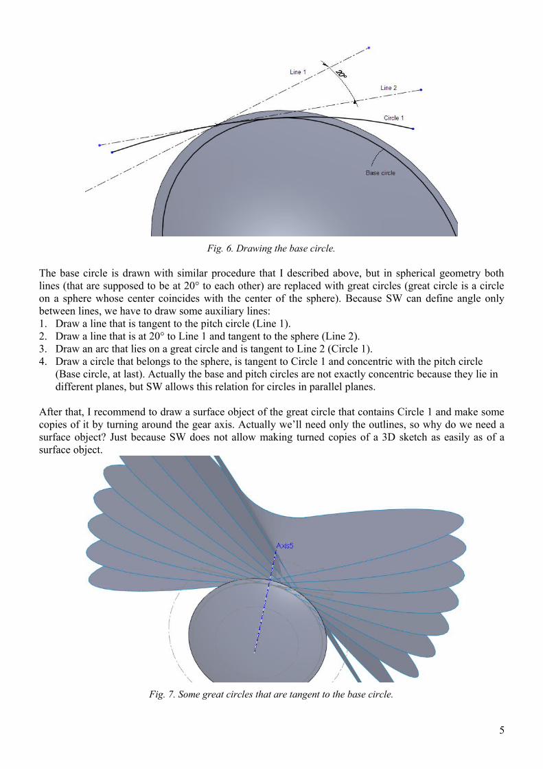
Fig. 6. Drawing the base circle.
The base circle is drawn with similar procedure that I described above, but in spherical geometry both lines (that are supposed to be at 20° to each other) are replaced with great circles (great circle is a circle on a sphere whose center coincides with the center of the sphere). Because SW can define angle only between lines, we have to draw some auxiliary lines:1. Draw a line that is tangent to the pitch circle (Line 1).2. Draw a line that is at 20° to Line 1 and tangent to the sphere (Line 2).3. Draw an arc that lies on a great circle and is tangent to Line 2 (Circle 1).4. Draw a circle that belongs to the sphere, is tangent to Circle 1 and concentric with the pitch circle
(Base circle, at last). Actually the base and pitch circles are not exactly concentric because they lie in different planes, but SW allows this relation for circles in parallel planes.
After that, I recommend to draw a surface object of the great circle that contains Circle 1 and make some copies of it by turning around the gear axis. Actually we’ll need only the outlines, so why do we need a surface object? Just because SW does not allow making turned copies of a 3D sketch as easily as of a surface object.
Fig. 7. Some great circles that are tangent to the base circle.
5
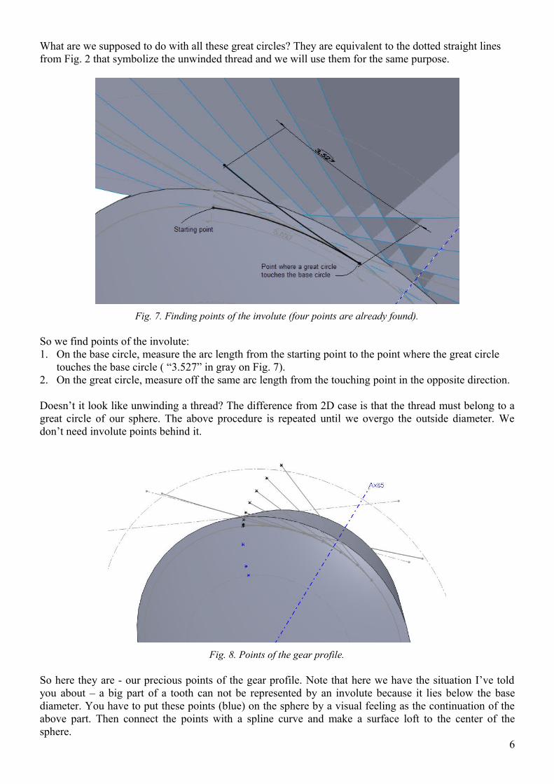
What are we supposed to do with all these great circles? They are equivalent to the dotted straight lines from Fig. 2 that symbolize the unwinded thread and we will use them for the same purpose.
Fig. 7. Finding points of the involute (four points are already found).
So we find points of the involute:1. On the base circle, measure the arc length from the starting point to the point where the great circle
touches the base circle ( “3.527” in gray on Fig. 7).2. On the great circle, measure off the same arc length from the touching point in the opposite direction.
Doesn’t it look like unwinding a thread? The difference from 2D case is that the thread must belong to a great circle of our sphere. The above procedure is repeated until we overgo the outside diameter. We don’t need involute points behind it.
Fig. 8. Points of the gear profile.
So here they are - our precious points of the gear profile. Note that here we have the situation I’ve told you about – a big part of a tooth can not be represented by an involute because it lies below the base diameter. You have to put these points (blue) on the sphere by a visual feeling as the continuation of the above part. Then connect the points with a spline curve and make a surface loft to the center of the sphere.
6
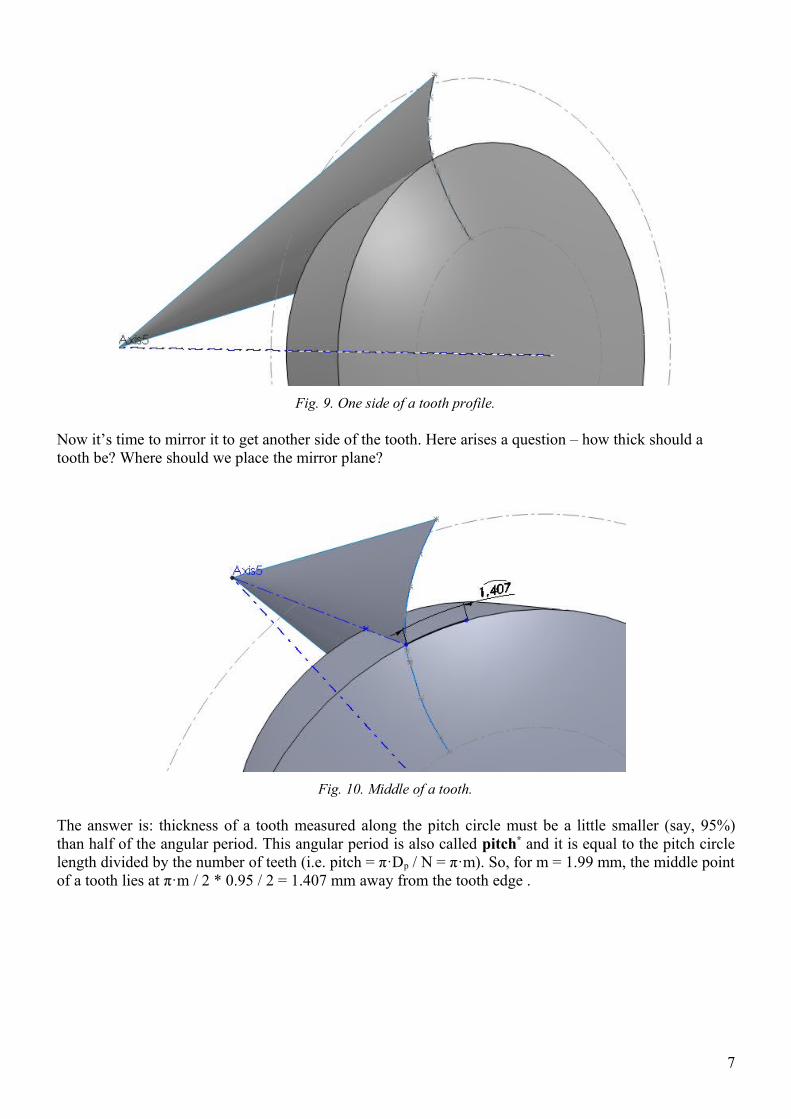
Fig. 9. One side of a tooth profile.
Now it’s time to mirror it to get another side of the tooth. Here arises a question – how thick should a tooth be? Where should we place the mirror plane?
Fig. 10. Middle of a tooth.
The answer is: thickness of a tooth measured along the pitch circle must be a little smaller (say, 95%) than half of the angular period. This angular period is also called pitch* and it is equal to the pitch circle length divided by the number of teeth (i.e. pitch = π·Dp / N = π·m). So, for m = 1.99 mm, the middle point of a tooth lies at π·m / 2 * 0.95 / 2 = 1.407 mm away from the tooth edge .
7
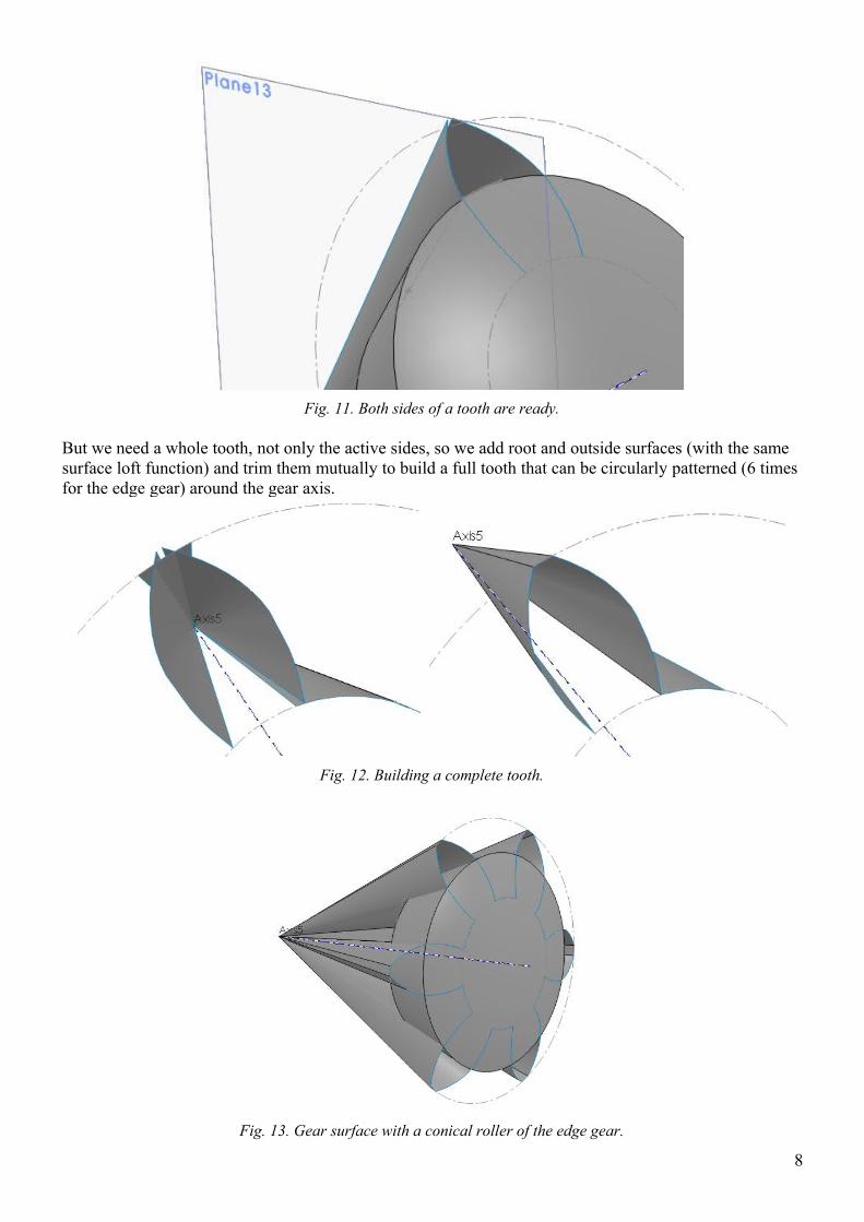
Fig. 11. Both sides of a tooth are ready.
But we need a whole tooth, not only the active sides, so we add root and outside surfaces (with the same surface loft function) and trim them mutually to build a full tooth that can be circularly patterned (6 times for the edge gear) around the gear axis.
Fig. 12. Building a complete tooth.
Fig. 13. Gear surface with a conical roller of the edge gear.
8
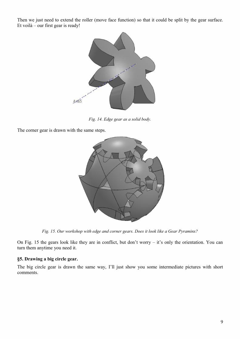
Then we just need to extend the roller (move face function) so that it could be split by the gear surface. Et voilà – our first gear is ready!
Fig. 14. Edge gear as a solid body.
The corner gear is drawn with the same steps.
Fig. 15. Our workshop with edge and corner gears. Does it look like a Gear Pyraminx?
On Fig. 15 the gears look like they are in conflict, but don’t worry – it’s only the orientation. You can turn them anytime you need it.
§5. Drawing a big circle gear.
The big circle gear is drawn the same way, I’ll just show you some intermediate pictures with short comments.
9
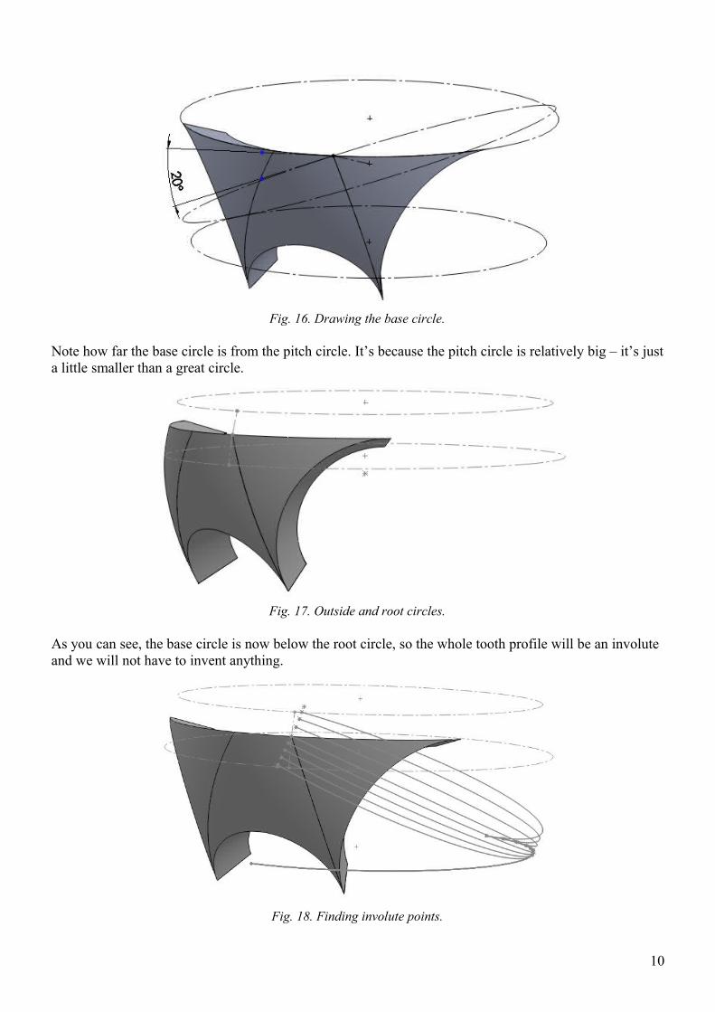
Fig. 16. Drawing the base circle.
Note how far the base circle is from the pitch circle. It’s because the pitch circle is relatively big – it’s just a little smaller than a great circle.
Fig. 17. Outside and root circles.
As you can see, the base circle is now below the root circle, so the whole tooth profile will be an involute and we will not have to invent anything.
Fig. 18. Finding involute points.
10
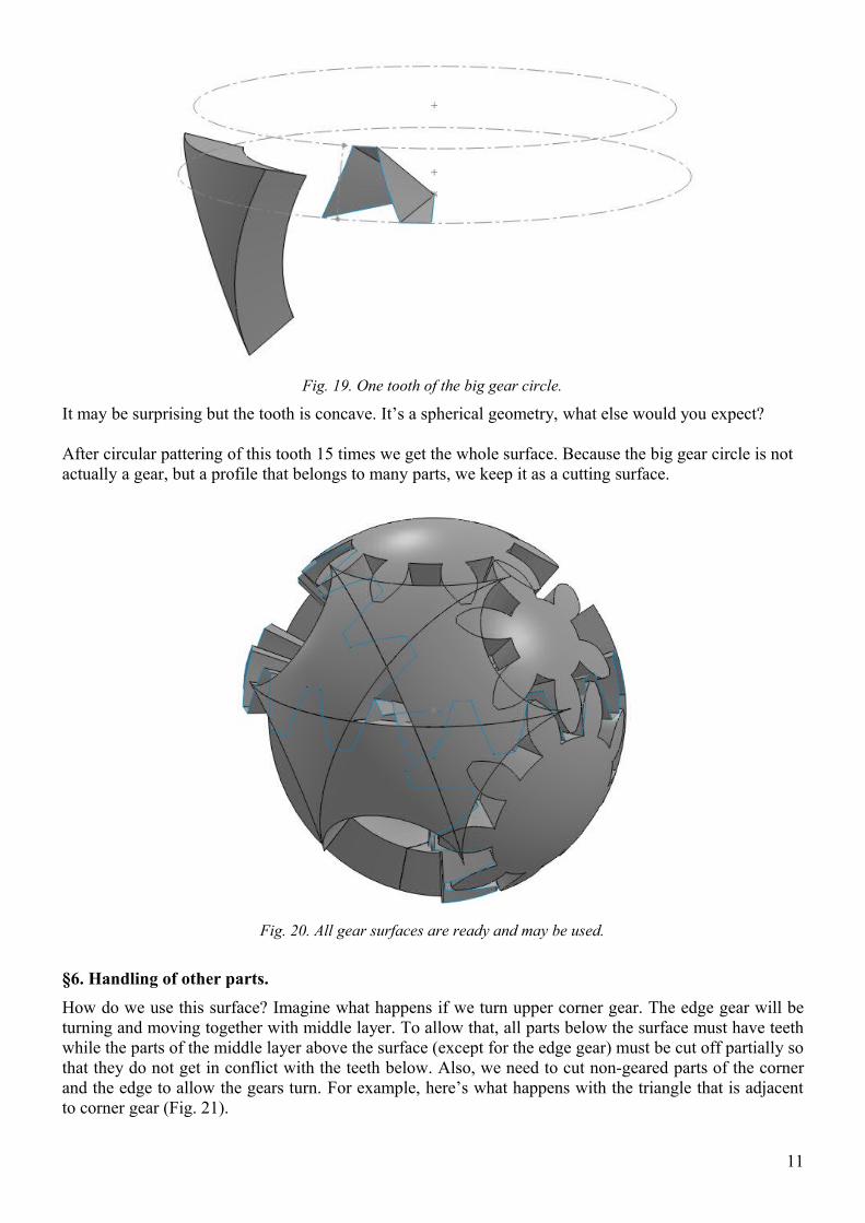
Fig. 19. One tooth of the big gear circle.
It may be surprising but the tooth is concave. It’s a spherical geometry, what else would you expect?
After circular pattering of this tooth 15 times we get the whole surface. Because the big gear circle is not actually a gear, but a profile that belongs to many parts, we keep it as a cutting surface.
Fig. 20. All gear surfaces are ready and may be used.
§6. Handling of other parts.
How do we use this surface? Imagine what happens if we turn upper corner gear. The edge gear will be turning and moving together with middle layer. To allow that, all parts below the surface must have teeth while the parts of the middle layer above the surface (except for the edge gear) must be cut off partially so that they do not get in conflict with the teeth below. Also, we need to cut non-geared parts of the corner and the edge to allow the gears turn. For example, here’s what happens with the triangle that is adjacent to corner gear (Fig. 21).
11
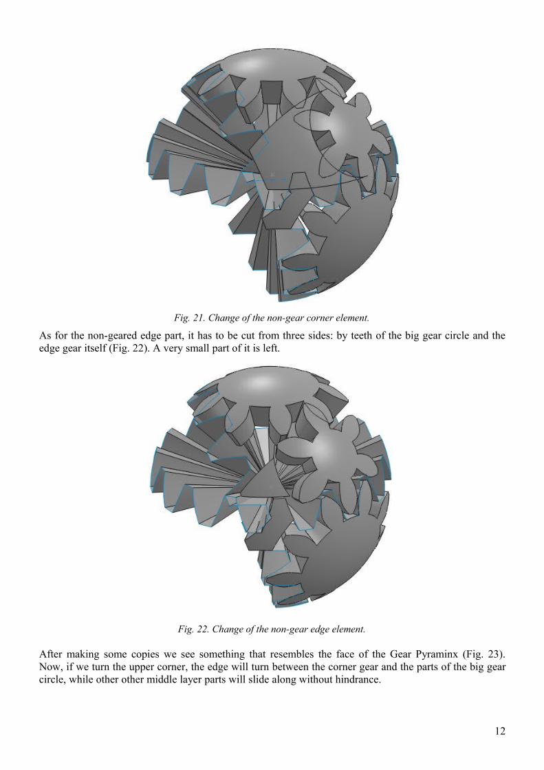
Fig. 21. Change of the non-gear corner element.
As for the non-geared edge part, it has to be cut from three sides: by teeth of the big gear circle and the edge gear itself (Fig. 22). A very small part of it is left.
Fig. 22. Change of the non-gear edge element.
After making some copies we see something that resembles the face of the Gear Pyraminx (Fig. 23). Now, if we turn the upper corner, the edge will turn between the corner gear and the parts of the big gear circle, while other other middle layer parts will slide along without hindrance.
12
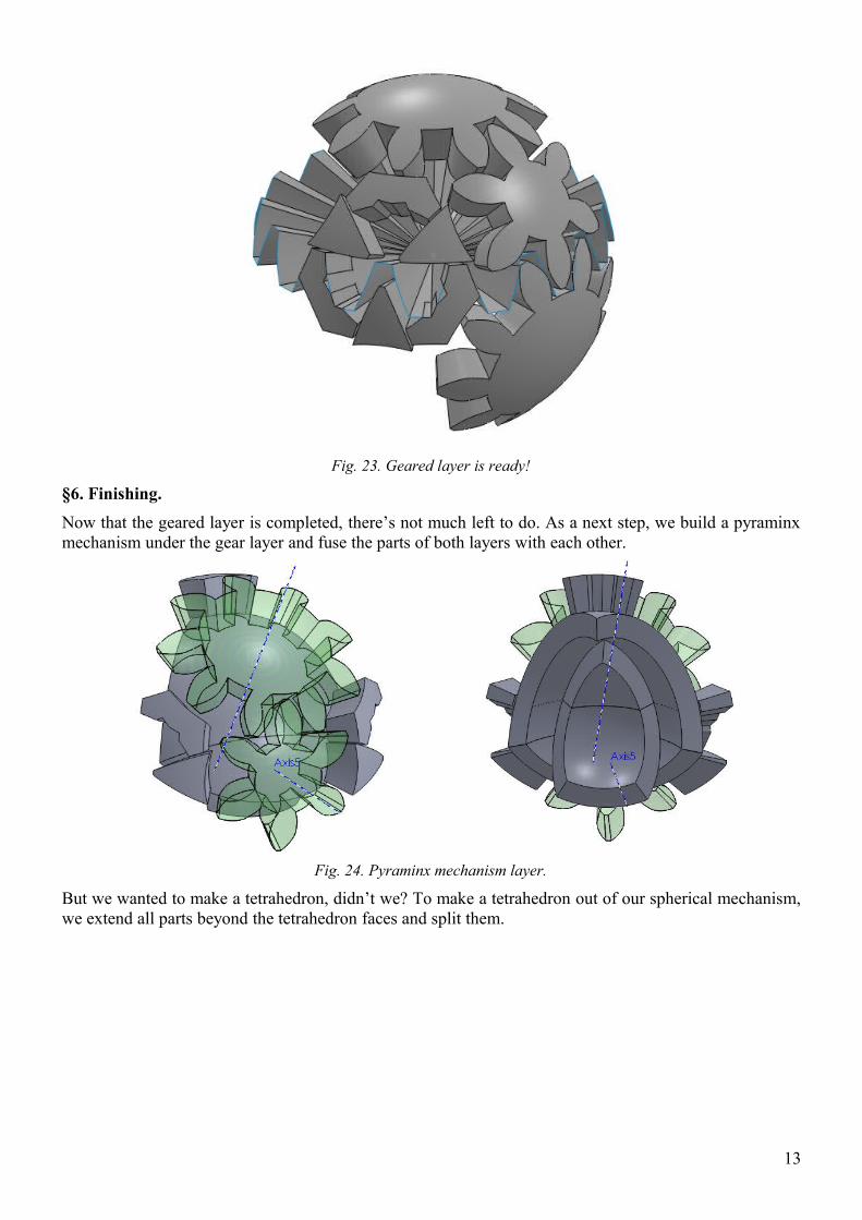
Fig. 23. Geared layer is ready!
§6. Finishing.
Now that the geared layer is completed, there’s not much left to do. As a next step, we build a pyraminx mechanism under the gear layer and fuse the parts of both layers with each other.
Fig. 24. Pyraminx mechanism layer.
But we wanted to make a tetrahedron, didn’t we? To make a tetrahedron out of our spherical mechanism, we extend all parts beyond the tetrahedron faces and split them.
13
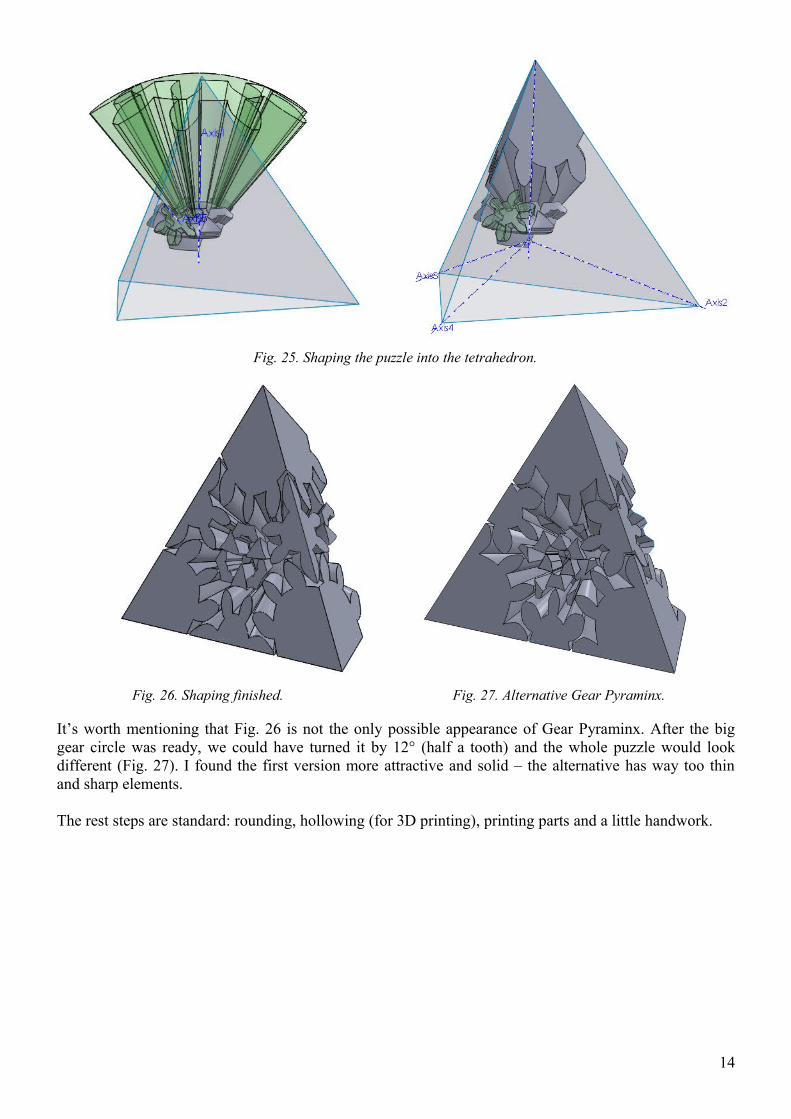
Fig. 25. Shaping the puzzle into the tetrahedron.
Fig. 26. Shaping finished. Fig. 27. Alternative Gear Pyraminx.
It’s worth mentioning that Fig. 26 is not the only possible appearance of Gear Pyraminx. After the big gear circle was ready, we could have turned it by 12° (half a tooth) and the whole puzzle would look different (Fig. 27). I found the first version more attractive and solid – the alternative has way too thin and sharp elements.
The rest steps are standard: rounding, hollowing (for 3D printing), printing parts and a little handwork.
14
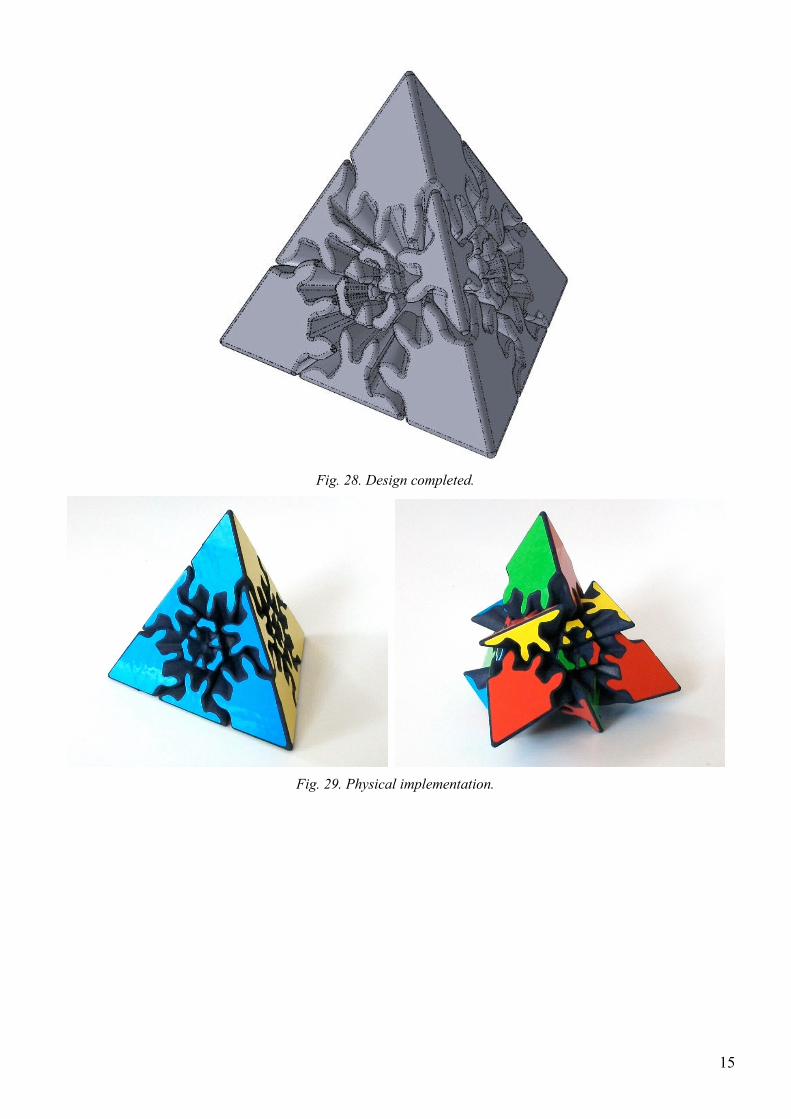
Fig. 28. Design completed.
Fig. 29. Physical implementation.
15