Embed Size (px)
Citation preview
Munich University of Applied SciencesDepartment of Computer Science and Mathematics,
Computer Science in Commerce
Diploma Thesis
Designing and Deploying High AvailabilityCluster Solutions in UNIX Environments
Stefan Peinkofer
2006-01-12Supervisor: Prof. Dr. Christian Vogt
Peinkofer Stefan (Geb. 12.06.1982)Matrikelnummer: 01333101
Studiengruppe 8W (Wintersemester 2005/2006)
Erklärunggemäß § 31 Abs. 7 RaPO
Hiermit erkläre ich, dass ich die Diplomarbeit selbständig verfasst,noch nicht anderweitig für Prüfungszwecke vorgelegt, keine an-deren als die angegebenen Quellen oder Hilfsmittel benützt sowiewörtliche und sinngemäße Zitate als solche gekennzeichnet habe.
Oberhaching, den 12.01.2006
Stefan Peinkofer
c©Stefan Peinkofer II [email protected]
Contents
1 Preface 11.1 Overview . . . . . . . . . . . . . . . . . . . . . . . . . . . . . . . . . . . . . 11.2 Background. . . . . . . . . . . . . . . . . . . . . . . . . . . . . . . . . . . . 21.3 The Zentrum für angewandte
Kommunikationstechnologien. . . . . . . . . . . . . . . . . . . . . . . . . . 21.4 Problem Description. . . . . . . . . . . . . . . . . . . . . . . . . . . . . . . 3
1.4.1 Central File Services. . . . . . . . . . . . . . . . . . . . . . . . . . . 41.4.2 Radius Authentication. . . . . . . . . . . . . . . . . . . . . . . . . . 41.4.3 Telephone Directory. . . . . . . . . . . . . . . . . . . . . . . . . . . 41.4.4 Identity Management System. . . . . . . . . . . . . . . . . . . . . . 5
1.5 Objective of the Diploma Thesis. . . . . . . . . . . . . . . . . . . . . . . . . 51.6 Typographic Conventions. . . . . . . . . . . . . . . . . . . . . . . . . . . . . 6
2 High Availability Theory 72.1 Availability and High Availability . . . . . . . . . . . . . . . . . . . . . . . . 72.2 Faults, Errors and Failures. . . . . . . . . . . . . . . . . . . . . . . . . . . . 8
2.2.1 Types of Faults. . . . . . . . . . . . . . . . . . . . . . . . . . . . . . 92.2.2 Planned Downtime. . . . . . . . . . . . . . . . . . . . . . . . . . . . 102.2.3 Dealing with Faults. . . . . . . . . . . . . . . . . . . . . . . . . . . . 11
2.3 Avoiding Single Points of Failure. . . . . . . . . . . . . . . . . . . . . . . . . 142.4 High Availability Cluster vs. Fault Tolerant Systems. . . . . . . . . . . . . . . 15
3 High Availability Cluster Theory 163.1 Clusters . . . . . . . . . . . . . . . . . . . . . . . . . . . . . . . . . . . . . . 163.2 Node Level Fail Over. . . . . . . . . . . . . . . . . . . . . . . . . . . . . . . 17
3.2.1 Heartbeats . . . . . . . . . . . . . . . . . . . . . . . . . . . . . . . . 183.2.2 Resources. . . . . . . . . . . . . . . . . . . . . . . . . . . . . . . . . 193.2.3 Resource Agents. . . . . . . . . . . . . . . . . . . . . . . . . . . . . 213.2.4 Resource Relocation. . . . . . . . . . . . . . . . . . . . . . . . . . . 213.2.5 Data Relocation. . . . . . . . . . . . . . . . . . . . . . . . . . . . . . 223.2.6 IP Address Relocation. . . . . . . . . . . . . . . . . . . . . . . . . . 273.2.7 Fencing. . . . . . . . . . . . . . . . . . . . . . . . . . . . . . . . . . 283.2.8 Putting it all Together. . . . . . . . . . . . . . . . . . . . . . . . . . . 31
3.3 Resource Level Fail Over. . . . . . . . . . . . . . . . . . . . . . . . . . . . . 33
III
CONTENTS
3.4 Problems to Address. . . . . . . . . . . . . . . . . . . . . . . . . . . . . . . 353.4.1 Split Brain . . . . . . . . . . . . . . . . . . . . . . . . . . . . . . . . 353.4.2 Fencing Loops. . . . . . . . . . . . . . . . . . . . . . . . . . . . . . 383.4.3 Amnesia . . . . . . . . . . . . . . . . . . . . . . . . . . . . . . . . . 393.4.4 Data Corruption . . . . . . . . . . . . . . . . . . . . . . . . . . . . . 40
3.5 Data Sharing . . . . . . . . . . . . . . . . . . . . . . . . . . . . . . . . . . . 413.5.1 Cluster File System vs. SAN File System. . . . . . . . . . . . . . . . 443.5.2 Types of Shared File Systems. . . . . . . . . . . . . . . . . . . . . . 453.5.3 Lock Management. . . . . . . . . . . . . . . . . . . . . . . . . . . . 473.5.4 Cache consistency. . . . . . . . . . . . . . . . . . . . . . . . . . . . 48
4 Designing for High Availability 504.1 System Management and Organizational Issues. . . . . . . . . . . . . . . . . 51
4.1.1 Requirements. . . . . . . . . . . . . . . . . . . . . . . . . . . . . . . 514.1.2 Personnel. . . . . . . . . . . . . . . . . . . . . . . . . . . . . . . . . 524.1.3 Security. . . . . . . . . . . . . . . . . . . . . . . . . . . . . . . . . . 534.1.4 Maintenance and Modifications. . . . . . . . . . . . . . . . . . . . . 544.1.5 Testing . . . . . . . . . . . . . . . . . . . . . . . . . . . . . . . . . . 574.1.6 Backup . . . . . . . . . . . . . . . . . . . . . . . . . . . . . . . . . . 574.1.7 Disaster Recovery. . . . . . . . . . . . . . . . . . . . . . . . . . . . 594.1.8 Active/Passive vs. Active/Active Configuration. . . . . . . . . . . . . 61
4.2 Hardware . . . . . . . . . . . . . . . . . . . . . . . . . . . . . . . . . . . . . 624.2.1 Network. . . . . . . . . . . . . . . . . . . . . . . . . . . . . . . . . . 634.2.2 Shared Storage. . . . . . . . . . . . . . . . . . . . . . . . . . . . . . 664.2.3 Server. . . . . . . . . . . . . . . . . . . . . . . . . . . . . . . . . . . 694.2.4 Cables. . . . . . . . . . . . . . . . . . . . . . . . . . . . . . . . . . . 704.2.5 Environment . . . . . . . . . . . . . . . . . . . . . . . . . . . . . . . 71
4.3 Software. . . . . . . . . . . . . . . . . . . . . . . . . . . . . . . . . . . . . . 734.3.1 Operating System. . . . . . . . . . . . . . . . . . . . . . . . . . . . . 754.3.2 Cluster Software. . . . . . . . . . . . . . . . . . . . . . . . . . . . . 764.3.3 Applications . . . . . . . . . . . . . . . . . . . . . . . . . . . . . . . 794.3.4 Cluster Agents. . . . . . . . . . . . . . . . . . . . . . . . . . . . . . 80
5 IT Infrastructure of the Munich University of Applied Sciences 825.1 Electricity Supply. . . . . . . . . . . . . . . . . . . . . . . . . . . . . . . . . 825.2 Air Conditioning . . . . . . . . . . . . . . . . . . . . . . . . . . . . . . . . . 835.3 Public Network . . . . . . . . . . . . . . . . . . . . . . . . . . . . . . . . . . 845.4 Shared Storage Device. . . . . . . . . . . . . . . . . . . . . . . . . . . . . . 855.5 Storage Area Network. . . . . . . . . . . . . . . . . . . . . . . . . . . . . . 86
6 Implementing a High Availability Cluster System Using Sun Cluster 886.1 Initial Situation . . . . . . . . . . . . . . . . . . . . . . . . . . . . . . . . . . 886.2 Requirements. . . . . . . . . . . . . . . . . . . . . . . . . . . . . . . . . . . 886.3 General Information on Sun Cluster. . . . . . . . . . . . . . . . . . . . . . . 89
c©Stefan Peinkofer IV [email protected]
CONTENTS
6.4 Initial Cluster Design and Configuration. . . . . . . . . . . . . . . . . . . . . 906.4.1 Hardware Layout. . . . . . . . . . . . . . . . . . . . . . . . . . . . . 906.4.2 Operating System. . . . . . . . . . . . . . . . . . . . . . . . . . . . . 956.4.3 Shared Disks. . . . . . . . . . . . . . . . . . . . . . . . . . . . . . .1016.4.4 Cluster Software. . . . . . . . . . . . . . . . . . . . . . . . . . . . .1026.4.5 Applications . . . . . . . . . . . . . . . . . . . . . . . . . . . . . . .114
6.5 Development of a Cluster Agent for Freeradius. . . . . . . . . . . . . . . . . 1236.5.1 Sun Cluster Resource Agent Callback Model. . . . . . . . . . . . . . 1236.5.2 Sun Cluster Resource Monitoring. . . . . . . . . . . . . . . . . . . . 1266.5.3 Sun Cluster Resource Agent Properties. . . . . . . . . . . . . . . . . 1266.5.4 The Sun Cluster Process Management Facility. . . . . . . . . . . . . 1306.5.5 Creating the Cluster Agent Framework. . . . . . . . . . . . . . . . . 1306.5.6 Modifying the Cluster Agent Framework. . . . . . . . . . . . . . . . 1316.5.7 Radius Health Checking. . . . . . . . . . . . . . . . . . . . . . . . .134
6.6 Using SUN QFS as Highly Available SAN File System. . . . . . . . . . . . . 1356.6.1 Challenge 1: SCSI Reservations. . . . . . . . . . . . . . . . . . . . .1366.6.2 Challenge 2: Meta Data Communications. . . . . . . . . . . . . . . . 1396.6.3 Challenge 3: QFS Cluster Agent. . . . . . . . . . . . . . . . . . . . .1436.6.4 Cluster Redesign. . . . . . . . . . . . . . . . . . . . . . . . . . . . .145
7 Implementing a High Availability Cluster System Using Heartbeat 1517.1 Initial Situation . . . . . . . . . . . . . . . . . . . . . . . . . . . . . . . . . .1517.2 Customer Requirements. . . . . . . . . . . . . . . . . . . . . . . . . . . . . .1517.3 General Information on Heartbeat Version 2. . . . . . . . . . . . . . . . . . . 152
7.3.1 Heartbeat 1.x vs. Heartbeat 2.x. . . . . . . . . . . . . . . . . . . . . .1537.4 Cluster Design and Configuration. . . . . . . . . . . . . . . . . . . . . . . .153
7.4.1 Hardware Layout. . . . . . . . . . . . . . . . . . . . . . . . . . . . .1537.4.2 Operating System. . . . . . . . . . . . . . . . . . . . . . . . . . . . .1567.4.3 Shared Disks. . . . . . . . . . . . . . . . . . . . . . . . . . . . . . .1667.4.4 Cluster Software. . . . . . . . . . . . . . . . . . . . . . . . . . . . .1677.4.5 Applications . . . . . . . . . . . . . . . . . . . . . . . . . . . . . . .1717.4.6 Configuring the STONITH Devices. . . . . . . . . . . . . . . . . . . 1737.4.7 Creating the Heartbeat Resource Configuration. . . . . . . . . . . . . 173
7.5 Development of a Cluster Agent for PostgreSQL. . . . . . . . . . . . . . . . 1827.5.1 Heartbeat Resource Agent Callback Model. . . . . . . . . . . . . . . 1827.5.2 Heartbeat Resource Monitoring. . . . . . . . . . . . . . . . . . . . .1847.5.3 Heartbeat Resource Agent Properties. . . . . . . . . . . . . . . . . . 1847.5.4 Creating the PostgreSQL Resource Agent. . . . . . . . . . . . . . . . 186
7.6 Evaluation of Heartbeat 2.0.x. . . . . . . . . . . . . . . . . . . . . . . . . . .1907.6.1 Test Procedure Used. . . . . . . . . . . . . . . . . . . . . . . . . . .1907.6.2 Problems Encountered During Testing. . . . . . . . . . . . . . . . . . 194
c©Stefan Peinkofer V [email protected]

CONTENTS
8 Comparing Sun Cluster with Heartbeat 1998.1 Comparing the Heartbeat and Sun Cluster Software. . . . . . . . . . . . . . . 199
8.1.1 Cluster Software Features. . . . . . . . . . . . . . . . . . . . . . . .1998.1.2 Documentation. . . . . . . . . . . . . . . . . . . . . . . . . . . . . .2018.1.3 Usability . . . . . . . . . . . . . . . . . . . . . . . . . . . . . . . . .2018.1.4 Cluster Monitoring. . . . . . . . . . . . . . . . . . . . . . . . . . . .2028.1.5 Support. . . . . . . . . . . . . . . . . . . . . . . . . . . . . . . . . .2038.1.6 Costs . . . . . . . . . . . . . . . . . . . . . . . . . . . . . . . . . . .2058.1.7 Cluster Software Bug Fixes and Updates. . . . . . . . . . . . . . . . 205
8.2 Comparing the Heartbeat and Sun Cluster Solutions. . . . . . . . . . . . . . . 2068.2.1 Documentation. . . . . . . . . . . . . . . . . . . . . . . . . . . . . .2068.2.2 Commercial Support. . . . . . . . . . . . . . . . . . . . . . . . . . .2068.2.3 Software and Firmware Bug Fixes. . . . . . . . . . . . . . . . . . . . 2078.2.4 Costs . . . . . . . . . . . . . . . . . . . . . . . . . . . . . . . . . . .2078.2.5 Additional Availability Features. . . . . . . . . . . . . . . . . . . . .2078.2.6 “Time to Market“. . . . . . . . . . . . . . . . . . . . . . . . . . . . .208
8.3 Conclusion . . . . . . . . . . . . . . . . . . . . . . . . . . . . . . . . . . . .208
9 Future Prospects of High Availability Solutions 2109.1 High Availability Cluster Software. . . . . . . . . . . . . . . . . . . . . . . .2109.2 Operating System. . . . . . . . . . . . . . . . . . . . . . . . . . . . . . . . .2129.3 Hardware . . . . . . . . . . . . . . . . . . . . . . . . . . . . . . . . . . . . .213
A High Availability Cluster Product Overview 214
c©Stefan Peinkofer VI [email protected]

List of Figures
3.1 Shared Storage. . . . . . . . . . . . . . . . . . . . . . . . . . . . . . . . . . 233.2 Remote mirroring. . . . . . . . . . . . . . . . . . . . . . . . . . . . . . . . . 243.3 Sample fail over 1. . . . . . . . . . . . . . . . . . . . . . . . . . . . . . . . . 313.4 Sample fail over 2. . . . . . . . . . . . . . . . . . . . . . . . . . . . . . . . . 323.5 Sample fail over 3. . . . . . . . . . . . . . . . . . . . . . . . . . . . . . . . . 333.6 Split Brain 1. . . . . . . . . . . . . . . . . . . . . . . . . . . . . . . . . . . . 363.7 Split Brain 2. . . . . . . . . . . . . . . . . . . . . . . . . . . . . . . . . . . . 363.8 Split Brain 3. . . . . . . . . . . . . . . . . . . . . . . . . . . . . . . . . . . . 36
4.1 Active/Active Configuration . . . . . . . . . . . . . . . . . . . . . . . . . . . 624.2 Active/Passive Configuration. . . . . . . . . . . . . . . . . . . . . . . . . . . 624.3 Inter-Switch Link Failure Without Spanning Tree. . . . . . . . . . . . . . . . 644.4 Inter-Switch Links With Spanning Tree. . . . . . . . . . . . . . . . . . . . . 654.5 Inter-Switch Link Failure With Spanning Tree. . . . . . . . . . . . . . . . . . 654.6 Redundant RAID Controller Configuration. . . . . . . . . . . . . . . . . . . . 674.7 Redundant Storage Enclosure Solution. . . . . . . . . . . . . . . . . . . . . . 684.8 Drawing a Resource Dependency Graph Step 1. . . . . . . . . . . . . . . . . 774.9 Drawing a Resource Dependency Graph Step 2. . . . . . . . . . . . . . . . . 774.10 Drawing a Resource Dependency Graph Step 3. . . . . . . . . . . . . . . . . 78
5.1 Electricity Supply of the Server Room. . . . . . . . . . . . . . . . . . . . . . 835.2 3510 Configuration. . . . . . . . . . . . . . . . . . . . . . . . . . . . . . . . 865.3 Fibre Channel Fabric Zone Configuration. . . . . . . . . . . . . . . . . . . . 87
6.1 PCI Card Installation Fire V440. . . . . . . . . . . . . . . . . . . . . . . . . 916.2 PCI Card Installation Enterprise 450. . . . . . . . . . . . . . . . . . . . . . . 926.3 Cluster Connection Scheme. . . . . . . . . . . . . . . . . . . . . . . . . . . . 936.4 Shared Disks Without I/O Multipathing. . . . . . . . . . . . . . . . . . . . .1006.5 Shared Disks With I/O Multipathing. . . . . . . . . . . . . . . . . . . . . . .1006.6 Resources and Resource Dependencies on the Sun Cluster. . . . . . . . . . . 1126.7 Cluster Interconnect and Meta Data Network Connection Scheme. . . . . . . 1466.8 Adopted Cluster Connection Scheme. . . . . . . . . . . . . . . . . . . . . . .148
7.1 PCI Card Installation RX 300. . . . . . . . . . . . . . . . . . . . . . . . . . .1547.2 Cluster Connection Scheme. . . . . . . . . . . . . . . . . . . . . . . . . . . .155
VII

LIST OF FIGURES
7.3 Important World Wide Names (WWNs) of a 3510 Fibre Channel Array. . . . 1597.4 New Fibre Channel Zone Configuration. . . . . . . . . . . . . . . . . . . . .1617.5 3510 Fibre Channel Array Connection Scheme. . . . . . . . . . . . . . . . . 1627.6 3510 Fibre Channel Array Failure. . . . . . . . . . . . . . . . . . . . . . . .1637.7 Resources and Resource Dependencies on the Heartbeat Cluster. . . . . . . . 1757.8 Valid STONITH Resource Location Configuration. . . . . . . . . . . . . . . 1767.9 Invalid STONITH Resource Location Configuration. . . . . . . . . . . . . . . 176
9.1 High Availability Cluster and Server Virtualization. . . . . . . . . . . . . . . 2119.2 Virtual Host Fail Over. . . . . . . . . . . . . . . . . . . . . . . . . . . . . . .212
c©Stefan Peinkofer VIII [email protected]
List of Tables
2.1 Classes of Availability 1 . . . . . . . . . . . . . . . . . . . . . . . . . . . . . 8
6.1 Boot Disk Partition Layout. . . . . . . . . . . . . . . . . . . . . . . . . . . . 966.2 Boot Disk Volumes V440. . . . . . . . . . . . . . . . . . . . . . . . . . . . . 986.3 Boot Disk Volumes Enterprise 450. . . . . . . . . . . . . . . . . . . . . . . . 99
7.1 Heartbeat Test Procedure. . . . . . . . . . . . . . . . . . . . . . . . . . . . .194
A.1 High Availability Cluster Products. . . . . . . . . . . . . . . . . . . . . . . .215
IX
Chapter 1
Preface
1.1 Overview
The diploma thesis is divided into nine main sections and an appendix.
• Section 1 contains the conceptual formulation and the goal of the diploma thesis as well
as the structure of the document.
• Section 2 discusses the basic theory of high availability systems in general.
• Section 3 contains the underlying theory of high availability cluster systems.
• Section 4 discusses design issues for high availability systems in general and for high
availability cluster systems in particular.
• Section 5 briefly introduces the infrastructure in which the concrete cluster implementa-
tions were deployed.
• Section 6 discusses the sample implementation of a high availability cluster solution
which is based on Sun’s cluster product Sun Cluster.
• Section 7 discusses the sample implementation of a high availability cluster solution
which is based on the Open Source cluster product Heartbeat.
• Section 8 contains a comparison of the two cluster products Sun Cluster and Heartbeat.
1
CHAPTER 1. PREFACE
• Section 9 gives a brief overview of the future trends of high availability systems in general
and high availability cluster systems in particular.
• The appendix contains references to various high availability cluster systems.
1.2 Background
In recent years, computers have dramatically changed the way we live and work. Almost ev-
erything in our “brave new world“ depends on computers. Communication, business processes,
purchasing and entertainment are just a few examples.
Unfortunately, computer systems are not perfect. Sooner or later every system will fail. When
your personal computer ends up with a blue screen while you are breaking the high score of your
fancy new game, it’s just annoying to you. But when a system supporting a business process of
a company breaks, many people get annoyed and the company loses money, either because the
employees can’t get their work done without the system or because the customers can’t submit
orders and therefore will change to a competitor.
The obvious solution to minimize system downtime is to deploy a spare system, which can
do the work when the primary system fails to do it. If the spare system is able to detect that
the primary system has failed and if it is able to take over the work automatically, the entity of
primary system and spare system is calledhigh availability cluster.
1.3 The Zentrum für angewandte
Kommunikationstechnologien
TheZentrum fürangewandteKommunikationstechnologien(ZaK) is the computer center of the
Munich University of Applied Sciences. The field of activity of the department is divided into
two main areas:
c©Stefan Peinkofer 2 [email protected]

1.4. PROBLEM DESCRIPTION
• University Computing - This area includes but is not limited to the following tasks:
– Operation of the fibre optics network between the headquarter and the branch offices
of the university.
– Operation of a central Identity Management System, which holds all students, pro-
fessors and employees.
– Operation of the central IT systems for E-mail, HTTP, DNS, backup and remote
disk space, for example.
– IT support for faculties and other departments of the university.
• Student Administration Computing - This area includes the following tasks:
– Development and maintenance of a student administration application, which is also
used by approximately twelve other German universities.
– Development and maintenance of online services for students, like exam registra-
tion, mark announcement and course registration.
1.4 Problem Description
Since the usage of the university computing infrastructure has dramatically increased over the
last few years, assuring availability of the central server and network systems has became a big
issue for the ZaK.
Currently most of the server systems deployed at the ZaK are not highly available. To decrease
the downtime in case of a hardware failure, the ZaK has a spare server for every deployed server
type. In case a server fails, the administrator takes the disks out of the failed server and puts
them into the spare server. This concept is from a time when the university IT systems weren’t
extremely important for most people. But since today nearly everyone in the university, be they
students, employees or university leaders, uses the IT infrastructure on a regular basis, this no
longer satisfies today’s availability demands.
c©Stefan Peinkofer 3 [email protected]
CHAPTER 1. PREFACE
Four of the most critical applications the ZaK provides to its customers, besides E-mail and
Internet presence are:
• Central file services for Unix and Windows, providing the user home directories.
• Radius authentication for dial-in and WLAN access to theMunich Science Network.
• The backend database for the internal telephone directory.
• The backend database for the Identity Management System.
The following sections show why the availability of these systems is so important.
1.4.1 Central File Services
If the central file server fails, the user’s home directories become inaccessible. Since the mail
server needs to access the user’s home directory to process incoming mail, the messages are
rejected with a “No such user“ error. Also, registration of new users through the Identity Man-
agement System will fail partly because it will not be able to create the user’s home directory.
1.4.2 Radius Authentication
If the Radius server is unavailable, users are not able to access the Munich Science Network
via dial-in or WLAN. Additionally, some Web sites that are protected by an authentication
mechanism using Radius are inaccessible.
1.4.3 Telephone Directory
If the backend database of the telephone directory fails, employees are unable to perform inter-
nal directory searches. This is so critical because the telephone directory is frequently used by
the university leaders.
c©Stefan Peinkofer 4 [email protected]

1.5. OBJECTIVE OF THE DIPLOMA THESIS
1.4.4 Identity Management System
If the backend database of the Identity Management System is unavailable, users are not able
to:
• enable their accounts for using the computers of the ZaK and some faculties
• change or reset their passwords
• use laboratories which are protected by the card reader access control system of the Iden-
tity Management System
• access the Web applications for exam registration, mark announcement and course regis-
tration
1.5 Objective of the Diploma Thesis
The main objective of this diploma thesis is to provide the ZaK with two reference implemen-
tations of high availability clustered systems:
• A file server cluster runningNFS, Samba, theSAN file system SUN SAM/QFSandRadius.
• A database cluster runningPostgreSQL.
The file server cluster will be based on Sun Solaris 10 using the Sun Cluster 3.1 high availabil-
ity software. The database cluster will be based on Red Hat Enterprise Linux 4.0 and the Open
Source cluster software Heartbeat 2.0.
This thesis should provide the Unix administrators of the ZaK with the knowledge and ba-
sic experience that is needed to make other services highly available and to decide which of the
two cluster systems is appropriate for the specific service. However, this thesis should not be
understood as a replacement of the actual hardware and software documentation.
c©Stefan Peinkofer 5 [email protected]
CHAPTER 1. PREFACE
1.6 Typographic Conventions
The following table describes the typographic changes that are used in this thesis.
• AaBbCc123 - The names of commands, configuration variables, files, directories and
hostnames.
• AaBbCc123- New terms and terms to be emphasized.
In addition to that, sometimes the construct <description> is used. This has to be understood as
a placeholder for the value which is described in the angle bracket.
c©Stefan Peinkofer 6 [email protected]

Chapter 2
High Availability Theory
2.1 Availability and High Availability
A system is considered available if it is able to do the work for which it was designated. Avail-
ability is the probability that the system is available over a specific period of time. It is measured
by the ratio between system uptime and downtime.1
Availability = UptimeUptime+Downtime
In more theoretical discussions, the termuptime is often replaced by the termMean Time
BetweenFailure (MTBF) and the termdowntimeis replaced by the termMeanTimeTo Repair
(MTTR).
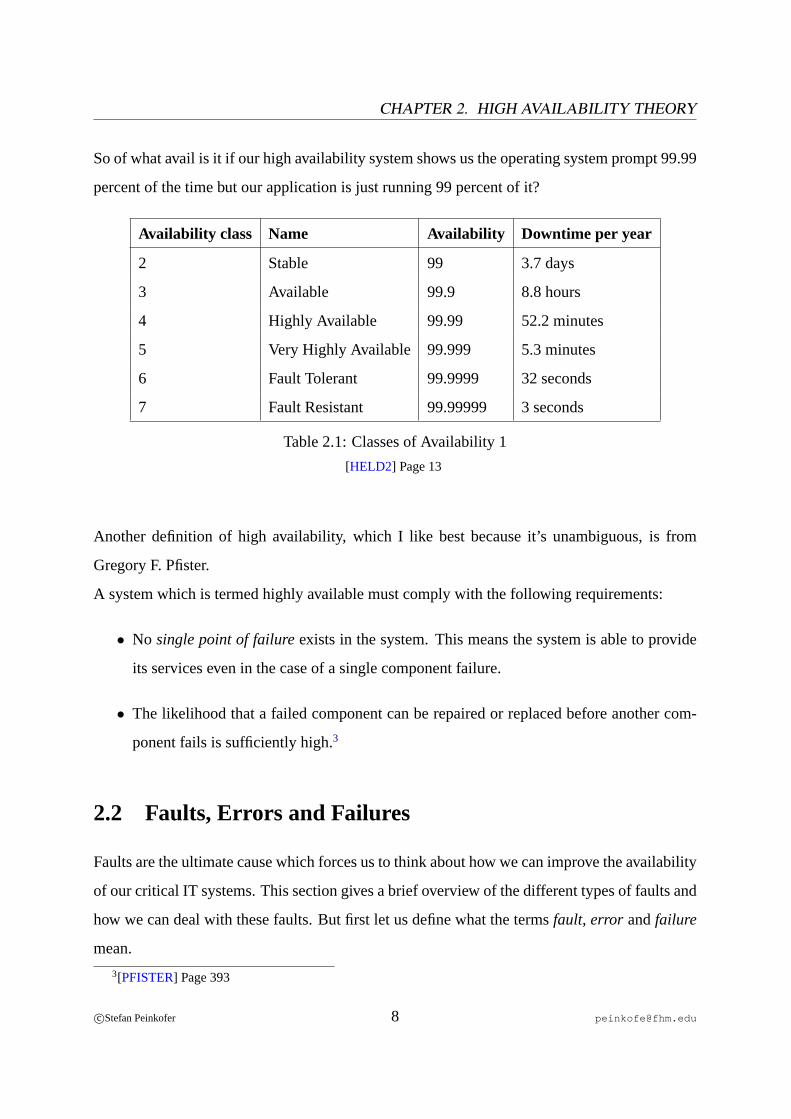
If we ask people what high availability is, they will probably show us something like table
2.1, which tells us the maximum amount of time a system is allowed to be unavailable per year.
The answer to our question would then be, “If it has a certain number of nines, it is highly
available“. At first glance, this seems reasonable because availability is measured by system
downtime.2 But if system vendors say, “Our high availability system is available 99.99 percent
of the time“, by “available“, they normally mean that it is showing an operating system prompt.
1[HELD1] Page 22[PFISTER] Pages 383-385
7
CHAPTER 2. HIGH AVAILABILITY THEORY
So of what avail is it if our high availability system shows us the operating system prompt 99.99
percent of the time but our application is just running 99 percent of it?
Availability class Name Availability Downtime per year
2 Stable 99 3.7 days
3 Available 99.9 8.8 hours
4 Highly Available 99.99 52.2 minutes
5 Very Highly Available 99.999 5.3 minutes
6 Fault Tolerant 99.9999 32 seconds
7 Fault Resistant 99.99999 3 seconds
Table 2.1: Classes of Availability 1
[HELD2] Page 13
Another definition of high availability, which I like best because it’s unambiguous, is from
Gregory F. Pfister.
A system which is termed highly available must comply with the following requirements:
• No single point of failureexists in the system. This means the system is able to provide
its services even in the case of a single component failure.
• The likelihood that a failed component can be repaired or replaced before another com-
ponent fails is sufficiently high.3
2.2 Faults, Errors and Failures
Faults are the ultimate cause which forces us to think about how we can improve the availability
of our critical IT systems. This section gives a brief overview of the different types of faults and
how we can deal with these faults. But first let us define what the termsfault, error andfailure
mean.
3[PFISTER] Page 393
c©Stefan Peinkofer 8 [email protected]
2.2. FAULTS, ERRORS AND FAILURES
• Fault / Defect- Anything that has the potential to prevent a functional unit from operating
in the way it was meant to. Faults in software are often referenced asbugs.
• Error - An error is a discrepancy between the observed and the expected behavior of a
functional unit. Errors are caused by faults that occur.
• Failure - A failure is a situation in which a system is not able to provides its services in
the expected manner. Failures result from uncorrected errors.4
2.2.1 Types of Faults
We can distinguish between three types of faults:
• Persistent Faults- Faults that appear and, without human intervention, don’t disappear.
Hardware and software can contain this type of fault in equal measure. Persistent faults
in hardware could be caused by a broken wire or micro chip, for example. In software
these faults can be caused by a design error in an application module or an inadequate
specification of the module. Persistent faults are easy to analyze. In case of a persistent
hardware fault, normally a maintenance light will flash on the affected units. If this is
not the case, we can still find the defective parts by changing the units consecutively. To
analyze persistent software faults, we can normally find a sequence of actions which will
result in the occurrence of the specific fault. That makes it easy to locate and fix the
problem. Even if the software cannot be fixed immediately, it is very likely that we will
find a procedure to work around the bug.5
• Transient Faults - Faults that appear and after a while disappear. This type of fault
appears in the hardware of the system because of outside influences like electrical in-
terferences, electrical stress peaks and so on. Software on the other hand can’t contain
transient faults. Although faults in the software may appear as transient faults, these faults
are persistent faults, activated through a procedure which is too complex to reproduce it.6
4[ELLING] Page 5, [BENEDI]5[SOLTAU] Page 146[SOLTAU] Page 14, [MENEZES] Page 1
c©Stefan Peinkofer 9 [email protected]
CHAPTER 2. HIGH AVAILABILITY THEORY
• Intermittent Faults - Faults that are similar to transient Faults but reappear after some
time. Like transient faults this type is a hardware only fault. It can be caused by overheat-
ing under high load or loose contacts, for example.7
2.2.2 Planned Downtime
When people think of downtime, they first associate it with a failure. That’s what we refer to as
unplanned downtime. But there is another type of downtime, namely the result of an intended
system shutdown. This type of downtime is termed asplanned downtime. Planned downtime
is mostly required to perform maintenance tasks like adding or replacing hardware, applying
patches or installing software updates. If these maintenance tasks cannot be performed at a
time when the system does not need to be available8, planned downtime can be considered a
failure. Companies purchase IT Systems to make money. From the company’s point of view
it makes no difference whether the system is not available because of an unplanned or planned
downtime. It is not making money, so it is broken.9
There is also another point which makes planned downtime an issue we should think about. The
ratio between planned and unplanned downtime is approximately10 two-thirds to one-third11.
The reasons which make planned downtime less bad than planned downtime is that we can
schedule planned downtime during hours when it will result in the lowest revenue losses12 and
we can prenotify users of the downtime, so they can plan to do something else while the system
maintenance is performed.13
7[ANON1]8Outside business hours for example.9[SOLTAU] Pages 14 - 15
10It highly depends on whom we ask.11[MARCUS] Page 1212[ANON2]. [SOLTAU] Page 1513[PFISTER]
c©Stefan Peinkofer 10 [email protected]
2.2. FAULTS, ERRORS AND FAILURES
2.2.3 Dealing with Faults
High availability systems are typically based on normal server hardware. Therefore the com-
ponents in these systems will fail at the same rates as they would in normal systems. The
difference between a normal system and a high availability system is the way in which they
respond to faults. This fault responding process can be divided into six elementary steps.
2.2.3.1 Fault Detection
To detect faults, high availability systems use so-called agents or probes. Agents are programs
which monitor the health of a specific hardware or software component and provide this health
information to a high availability management process. Monitoring is done by querying status
information from a component or by actively checking a component, or by both.14
For example, an agent which monitors the operation of the cooling fans can just query the
fan status from the hardware. To monitor a database application an agent program could query
the status of the application15 and/or it could perform a sequence of database transactions and
see whether they complete successfully.
2.2.3.2 Fault Isolation
Fault isolation or fault diagnosis is the process of determining which component and which
fault in the component caused the error. Since every agent is normally responsible for a single
component, the system can identify the erroneous component by determining firstly the agent
which reported the fault and secondly the component the agent is responsible for. After the
erroneous component is isolated, the system must determine which fault caused the component
to fail. However, in some error scenarios it is almost impossible to identify the fault accurately.
In this case the fault isolation process has to find out which faults could have caused the error.16
14[ELLING] Pages 7-9, [ANON3]15If supported by the application.16[ANON4], [ELLING] Page 10, [RAHNAMAI ] Page 9
c©Stefan Peinkofer 11 [email protected]

CHAPTER 2. HIGH AVAILABILITY THEORY
For example, if the network fails because the network cable is unplugged, it’s easy to iden-
tify the fault because the link status of the network interface card will switch to off. Since the
error signature “link status is off“ is unique for the fault “no physical network connection avail-
able“, it’s the only possible fault that could cause the network failure. But if the network fails
because the connected network cable is too long, it’s impossible to identify the fault unambigu-
ously. This is because the error signature for this fault is “unexpected high bit error rate“, which
is also the error signature of other faults like electromagnetic interferences.17
2.2.3.3 Fault Reporting
The fault reporting process informs components and the system administrator about a detected
fault. This can be done in various ways: Writing log files, sending E-mails, issuing a SNMP
(Simple NetworkManagementProtocol) trap, feeding a fault database and many more ways.
Independent of the way in which fault reporting is done, the usability of fault reports depends
primarily on two factors:
• Accuracy of fault isolation - The more accurate the system can determine which com-
ponent caused an error and what the reason for the error is, the better and clearer fault
information can be provided to the administrators.
• Good prioritization of faults - Different faults have different importance to the adminis-
trator. Faults which can affect the availability of the system are of course more important
than faults which cannot. Additionally, faults of the latter type occur much more often
than the former ones. Reporting both types with the same priority to the system adminis-
trator makes it harder to respond to the faults in an appropriate manner, first because the
administrator may not be able to determine how critical the reported fault is and second
because the administrator may lose sight of the critical faults because of the huge amount
of noncritical ones.18
17[ELLING] Page 818[ELLING] Pages 10 - 12
c©Stefan Peinkofer 12 [email protected]

2.2. FAULTS, ERRORS AND FAILURES
2.2.3.4 Fault Correction
A fault correction process can only be performed by components which are able to detect and
correct errors internally and transparent to the other components. The most famous example for
this type of component isError CorrectingCode(ECC) memory. On each memory access it
checks the requested data for accuracy and automatically corrects invalid bits before it passes
the data to the requestor.19
2.2.3.5 Fault Containment
Fault containment is the process of trying to prevent the effects of a fault from spreading out over
a defined boundary. This should prevent a fault from setting off other faults in other components.
If two componentsA andB share one common componentC, like a SCSI bus or a shared disk,
a fault in componentA could propagate over the shared componentC to the componentB. To
prevent this, the fault must be contained in componentA. On high availability cluster systems,
for example the typical boundary for faults are servers. This means that containing a fault is
done by keeping the faulty server off the shared components.20
2.2.3.6 System Reconfiguration
The system reconfiguration step recovers the system from a non-correctable fault. The way in
which the system is reconfigured depends on the fault. For example, if a network interface card
of a server fails, the server will use an alternate network interface card. If a server in a high
availability cluster system fails completely, for example, the system will use another server to
provide the services of the failed one.21
19[ELLING] Pages 6 and 1120[ELLING] Pages 12 - 1321[ELLING] Pages 13 - 14
c©Stefan Peinkofer 13 [email protected]
CHAPTER 2. HIGH AVAILABILITY THEORY
2.3 Avoiding Single Points of Failure
A Single Point Of Failure (SPOF) is anything that will cause unavailability of the system if it
fails. Obvious SPOFs are the hardware components of the high availability system like cables,
controller cards, disks, power supplies, and so on. But there are also other types of SPOFs, such
as applications, network and storage components, external services like DNS, server rooms,
buildings and many more. To prevent all these components from becoming SPOFs, the common
strategy is to keep them redundant. So in case the primary component breaks, the secondary
component takes over.
Although it is easy to remove a SPOF, it may be very complex firstly to figure out the SPOFs
and secondly determine whether it is cost effective to remove the SPOF. To find the SPOFs we
must look at the whole system workflow, from the data backend over the HA system itself to
the point of the clients. This requires a massive engineering effort of many different IT sub-
divisions. After all the SPOFs are identified, we must do a risk analysis for every component
which constitutes a SPOF to find out how expensive a failure of the component would be. The
definition of risk is:
Risk = Occurrence Possibility ∗ Amount of Loss
The occurrence possibility has to be estimated. To give a good estimation, we could use the
mean time between failure (MTBF) information of components or assurance field studies or
consult an expert. To calculate the amount of loss, we must know how long it takes to recover
from a failure of the specific component and how much money we lose because of the system
unavailability. After we calculate the risk, we can compare it to the costs of removing the SPOF
to see if we should either live with the risk or eliminate the SPOF.22
22[MARCUS] Pages 27 - 28 and 32 - 33
c©Stefan Peinkofer 14 [email protected]
2.4. HIGH AVAILABILITY CLUSTER VS. FAULT TOLERANT SYSTEMS
2.4 High Availability Cluster vs. Fault Tolerant Systems
Many people use the termshigh availability clusterandfault tolerant systeminterchangeably
but there are big differences between them. Fault tolerant systems use specialized, proprietary
hardware and software to guarantee that an application is available without any interruption.
This is achieved not only by duplicating each hardware component but also by replicating every
software process of the application. So in the worst case scenario, in which the memory of a
server fails, the replicated version of the application continues to run. In contrast to that a high
availability cluster doesn’t replicate the application processes. If the memory of a server in a
high availability cluster fails, the application gets restarted on another server. For a database
system, running on a high availability cluster, this means for instance that the users get dis-
connected from the database and all their not yet committed transactions are lost. As soon as
they reconnect, they can normally start their work again. The users of a fault tolerant database
system would in this scenario not even notice that something is going wrong with their database
system.23
However, high availability clusters have some advantages compared to fault tolerant systems.
They are composed of commodity hardware and software so they are less expensive and can
be deployed in a wider range of scenarios. While performing maintenance tasks like adding
hardware or applying patches, application availability is not impacted because most of these
tasks can be done on server after server. Additionally, high availability clusters are able to re-
cover from some types of software faults, which are single points of failures in fault tolerant
systems.24
23[BENDER] Page 324[ELLING] Page 53
c©Stefan Peinkofer 15 [email protected]
Chapter 3
High Availability Cluster Theory
What has been discussed in the last chapter applies to high availability systems in general. This
is why the termhigh availability clusterhas been avoided as far as possible. Although people
often usehigh availability systemandhigh availability clustersynonymously, a system which
is highly available doesn’t necessarily have to be a cluster. As the definition in chapter2.1 on
page7 said, a high availability system must not contain a single point of failure. This character-
istic applies to some non-clustered systems as well. Especially high-end, enterprise scale server
systems like theSUN Fire Enterpriseor HP Superdomeservers are designed without a single
point of failure and because of their hot-plug functionality of almost every component, a failed
component can be replaced without service disruption.
In the following chapter we will discuss the basic theory of high availability clusters. We will
look at the building blocks of a high availability cluster, how they work together, what particular
problems arise and how these problems are solved.
3.1 Clusters
A cluster in the context of computer science is an accumulation of interconnected standalone
computers, working together on a common problem. To the users, the cluster thereby acts like
one large consistent computer system. Usually there are two reasons to build a cluster, either
16
3.2. NODE LEVEL FAIL OVER
to deliver the computing power or the reliablility1 that a single computer system can’t achieve
without being much more expensive than a cluster2. The several computers forming a cluster
are usually referenced ascluster nodes. The boot up of the first cluster node will initialize the
cluster. This is referenced asincarnationof a cluster. A cluster node which is up and running
and delivers its computing resources to the cluster is referenced ascluster member. Therefore,
the event when a node starts to deliver its computing resources to an already incarnated cluster
is referenced asjoining the cluster.
A high availability cluster, in the context of this thesis, is a cluster which makes anappli-
cation instancehighly available by running the application instance on one cluster node and
starting the application instance on another node in case either the application instance itself or
the cluster node the application instance ran on failed. This means that on a high availability
cluster, no more than one specific instance of an application is allowed to run at a time. An
application instance is thereby defined as the collectivity of belonging together processes of the
application, the corresponding IP address on which the processes are listening and the files and
directories in which theconfigurationandapplication state informationfiles of the application
instance are stored. Application state information files are, for instance,.pid files or log files.
So on a high availability cluster it is only possible to run an specific application more than once
at a time if each set of belonging together processes listens on a dedicated IP address and uses
a dedicated set of configuration and application state information files.
3.2 Node Level Fail Over
A cluster typically consists of two or more nodes. To achieve high availability, the basic concept
of a high availability cluster is known asfail over. When a cluster member fails, the other cluster
members will do the work of the failed member. This concept sounds rather simple, but there
are a few issues we have to look at:
1Or both.2[WIKI1]
c©Stefan Peinkofer 17 [email protected]
CHAPTER 3. HIGH AVAILABILITY CLUSTER THEORY
1. How can the other members know that another member failed?
2. How can the other members know which work the failed member did and which things
they need in order to do the work?
3. Which cluster member(s) should do the work of the failed node?
4. How can the other members access the data the failed node used for its work?
5. How do the clients of the failed node know which member they have to contact if a fail
over occurred?
3.2.1 Heartbeats
Cluster members continuously send so-calledheartbeatmessages to the other cluster members.
To transport these heartbeat messages, several communication paths like normalEthernetcon-
nections, proprietarycluster interconnects, serialconnections orI/O interconnectscan be used.
These heartbeat messages indicate to the receiver that the cluster member which sent it is op-
erational. Every cluster member expects to receive another heartbeat message from every other
cluster member within a specific time interval. When an expected heartbeat message fails to
appear within the specified time, the node whose heartbeat message is missing is considered
dead.
Of course real-life heartbeat processing is not that easy. The problem is that sending and re-
ceiving heartbeat messages is ahard real-timetask because a node has to send its next heartbeat
message before exceeding a deadline which is given by the other nodes. Unfortunately, almost
none of the common operating systems which are used for high availability clustering, are capa-
ble of handling hard real-time task. The only things that can be done to alleviate the problem are
giving the heartbeat process the highest scheduling priority and preventing parts of the heartbeat
process from getting paged out and, of course, preventing the complete heartbeat process from
getting swapped out onto disk. However, this doesn’t solve the problem completely. Maybe the
node managed to send the heartbeat message within the deadline but one or some of the other
c©Stefan Peinkofer 18 [email protected]
3.2. NODE LEVEL FAIL OVER
nodes didn’t receive the message by the deadline. Reasons could be that network traffic is high
or some nodes are experiencing a high workload and hence the message receive procedure from
the network card to the heartbeat process is taking too long. To alleviate the problem further, we
can use dedicated communication paths for the heartbeat messages, though this doesn’t solve
the problem completely. The last thing we can do is set the deadline to a reasonably high value
so that the probability of a missed deadline is low enough or consider a node dead only if a
specific number of heartbeats have not occurred.3 However, the problem itself cannot be elimi-
nated completely and, therefore, the cluster system must be able to respond appropriately, when
the problem occurs. How cluster systems do this in particular is discussed in chapter3.4.1on
page35.
When we denote a node as failed we mean from now on that the other cluster members no
longer receive heartbeat messages from the node, regardless of the cause.
3.2.2 Resources
Everything in a cluster which can be failed over from one cluster member to another is called a
resource. The most famous examples for resources are application instances, IP addresses and
disks. Resources can depend on one another. For example an application may depend on an IP
address to listen and a disk which contains the data of the application.
A cluster system must be aware of the resources and their dependencies. An application which
runs on a cluster node but of which the cluster system is not aware is not highly available be-
cause the application won’t be started elsewhere if the node the application is currently running
on dies. On the other hand, an application resource which depends on a disk resource also isn’t
highly available if the cluster system is not aware of the dependency. In case the cluster member
currently hosting the resources dies, the application resource may get started on one member
and the disk may be mounted on another member. Even if they get started on the same node,
3[PFISTER] Pages 419 - 421
c©Stefan Peinkofer 19 [email protected]

CHAPTER 3. HIGH AVAILABILITY CLUSTER THEORY
they may get started in the wrong order. Even if they get started in the right order, the cluster
system would start the application even if it failed in mounting the shared disk.
In addition to that, resources can depend not only on resources which have to be started on
the same node. They may just depend on a resource which has to be online, independent of the
cluster member it runs on.4 For example anapplication serverlike Apache Tomcat may depend
on a MySQL database. But for Tomcat it’s not important that the MySQL database runs on the
same node.
Another challenge is that resources may not be able to run on all cluster nodes, for exam-
ple, because an application is not installed on all nodes or some nodes can’t access the needed
application data.
To keep track of all cluster resources, their dependencies and their potential host nodes, the
cluster systems use a cluster-wideresource repository.5 Since the cluster system itself usu-
ally cannot figure out what resources and what dependencies exist on the cluster6, it typically
provides a set of tools which allow the administrator to add, remove and modify the resource
information.
To define which resources must run on the same node, most cluster systems use so-calledre-
source groups. On these cluster systems, a resource group is the entity which will be failed over
to another node. Between the resources within a resource group, further dependencies have to
be specified to indicate the order in which the resources have to be started.7 To designate a
resource to depend on another resource running elsewhere in the cluster, the resources must be
put into two different resource groups and either a dependency between the two resources or a
4[PFISTER] Pages 398 - 4005[PFISTER] Page 3986That would be the optimal solution, but it’s very hard to implement.7[ELLING] Pages 102 - 104
c©Stefan Peinkofer 20 [email protected]
3.2. NODE LEVEL FAIL OVER
dependency between the two resource groups has to be specified8. For clarity reasons, method
two is preferable because in this case resource dependencies exist only within a resource group.
However, not all cluster systems stick with this.
3.2.3 Resource Agents
A cluster system contains many different types of resources. Almost anyresource typerequires
a customstart-upprocedure. As we already know, the cluster system knows which resources
exist and how they depend on another. But now there’s another question to answer. How does
the cluster system know what exactly it has to do to start a particular type of resource? The an-
swer to this question is, it doesn’t know and it doesn’t have to know. The cluster system leaves
this task to an external program or set of programs calledresource agents. Resource agents are
the key to one of the main features of high availability clusters. Almost any application can be
made highly available. All that is needed is a resource agent for the application.
What the cluster system knows about the start up of a resource is which resource agent it has to
call. Typically resources get not only started but also stopped or monitored. So the basic func-
tions a resource agent must provide arestart, stopandmonitor functions. The cluster system
tells the agent what it should do and the agent performs whatever is needed to carry out the task
and returns to the cluster system whether it was successful or not.
3.2.4 Resource Relocation
When a cluster member fails, the resources of the failed node have to be relocated on the remain-
ing cluster members. In a two-node cluster the decision of which node will host the resources is
straightforward. In a cluster of three or more nodes things get more difficult. The best solution
would be to distribute the resource groups among the remaining nodes in such a manner that
every node has roughly the same workload. An even better solution would be to distribute the
resource groups in such a manner that theservice level agreementsof the various applications
8Dependent on the used cluster system.
c©Stefan Peinkofer 21 [email protected]

CHAPTER 3. HIGH AVAILABILITY CLUSTER THEORY
are violated as few as possible. However this requires a facility which has a comprehensive
understanding of the workload or the service levels of the applications. Some cluster systems
which are tightly integrated with the operating system9 have such facilities and therefore can
provide this type of solution. But the majority of high availability cluster systems are not so
smart.10 They use various more or less good solutions like:
• Call a user defined program which determines which node is best for a particular resource
group.11
• Let the administrator define constraints on how resource groups should be allocated
among the nodes.
• Use an user defined list of nodes for each resource group which indicates that the resource
group should be run on the first node in the list, if this is not possible on the second node
in the list, and so on.
• Distribute the resource groups so that every cluster member runs roughly the same number
of resources.
3.2.5 Data Relocation
If we want to fail over an application from one node to another, we have to fail over the ap-
plication data as well. Basically there are two ways to achieve this. Either deploy a central
disk to which all/some cluster nodes are connected or replicate the data from the application
hosting node to all/some of the other nodes. Both methods have benefits and drawbacks. In the
following section, we will discuss how the two techniques basically work and compare them to
each other.
9Like the VMScluster.10[PFISTER] Pages 416 - 41711[PFISTER] Page 416
c©Stefan Peinkofer 22 [email protected]

3.2. NODE LEVEL FAIL OVER
3.2.5.1 Shared Storage
A shared storageconfiguration requires that every cluster member which should potentially be
able to access a particular set of application data is physically connected to one or more central
disk(s) which contain(s) the application data. Therefore, as figure3.1 shows, a special type of
I/O interconnect is required which must allow more than one host to be attached to it. In the
past, a couple of proprietary I/O interconnects with this feature existed12. Nowadays mostly
two industry standard I/O interconnects are used:
• Multi-Initiator SCSI (Small ComputerSystemInterface) is used in low-end, two-node
cluster systems. The SCSI bus allows two hosts to be connected to the ends of the bus
and share the disks which are connected in between.
• Fibre Channel(FC) is used in high-end and more than two-node cluster systems. With
fibre channel it’s possible to connect many disks and hosts together in a storage network.
This is often referred to asStorageAreaNetwork(SAN).
Shared Disks
I/O Interconnect
Public Network
Figure 3.1: Shared Storage
12And probably still exist.
c©Stefan Peinkofer 23 [email protected]

CHAPTER 3. HIGH AVAILABILITY CLUSTER THEORY
3.2.5.2 Remote Mirroring
A remote mirroringconfiguration typically uses a network connection to replicate the data. As
figure3.2 shows, every node needs a local attached disk which holds a copy of the data and a
network connection to the other nodes. Depending on the application, the replication process
can be done in several intervals and on several levels. For example the data of a network file
server has to be replicated instantaneously on the disk block level, whereas the data of a domain
name server may just require a file level replication, done manually by the administrator, every
time he has changed something in the DNS files.
Updates
Local AttachedDisks
Local AttachedDisks
Public Network
Figure 3.2: Remote mirroring
However, in any case it must be ensured that every replication member holds the same data.
This means that a data update must be applied either on all members or on no member at all.
To achieve this, atwo-phase commit protocolcan be used. In phase one, every member tries
to apply the update but also remembers the state before the update. If a member successfully
applies the update it sends out an OK message. If it doesn’t update, it sends an ERROR message.
Phase two begins after all members have sent their message. If all members send an OK, the
c©Stefan Peinkofer 24 [email protected]

3.2. NODE LEVEL FAIL OVER
state before the update is discarded and the write call on the source host returns successfully.
If at least one member has sends an ERROR message, the members restore the state before the
update and the write call on the source host returns with an error.13
3.2.5.3 Shared Storage vs. Remote Mirroring
• Performance - The read and write performance of shared storage is virtually the same
as that of a local attached storage. Remote mirroring uses a local attached disk for read
operations, so the read performance can be the same as with shared storage. But the write
operations have to block until all replication targets have updated their data. In addition,
the replication source and target hosts must run a replication process which consumes
some CPU resources.14 So write performance is not as good as with shared storage but it
may be sufficient depending on the application which uses the data.
• Synchronisation - This is no problem for shared storage since only one potential data
source exists. Using thetwo-phase commit protocolfor remote mirroring ensures that the
data is kept in sync, but using it can be a performance issue. However, if the write call on
the source host returns immediately after the update was carried out on the local disk and
the replication targets are notified about the update, but does not wait until all targets have
updated their data successfully, data loss is possible, if a replication target is not able to
apply the update. Another problem with remote mirroring is that a node which is down
for some reason holds outdated data. So before the node can be put back in service again,
the data on the node has to be resynced.15 In addition to that it must be ensured that at
any point in time, only one replication source exists.
• Possible node distance- Multi-Initiator SCSI bus length is limited to 12 meters. Fibre
channel can span distances up to 10 kilometres without a repeating device. With the use
of repeating devices no theoretical distance limitation exists. With remote mirroring vir-
tually no distance limitation exists, either. However, the transmission delays have to be
13[SMITH]14[PFISTER] Page 40515[PFISTER] Page 406
c©Stefan Peinkofer 25 [email protected]

CHAPTER 3. HIGH AVAILABILITY CLUSTER THEORY
kept in mind for large distance fibre channel and remote mirroring configurations. Al-
though it is more critical for remote mirroring because the packets have to travel through
the TCP/IP stack, the delay of large distance fibre channel links cannot be ignored com-
pletely. For example, in a fibre optics cable light can be transmitted approximately one
metre in five nanoseconds16. If a target device is 10 kilometres away, we have around trip
distance of 20 km, since we must send a packet to the target and await a response from
it. With a distance of 20 kilometres we have a delay of 100 microseconds. A high per-
formance hard disk drive has amean access timeof 6 milliseconds17. So the delay of the
fibre channel link adds 1.66 percent of the disk’s mean access delay to the overall delay.
That is tolerable in most cases, but if we want to span a distance of 100 kilometres the
fibre channel link delay adds 16.66 percent of the disk’s mean access delay to the overall
delay. Especially for applications which perform many small random disk accesses this
might become a performance issue.
• Disaster tolerance- Since the SCSI bus length can be up to 12 meters, both cluster
nodes and the storage must be located in a single site. In case of a disaster like a flood for
instance the whole cluster may become unavailable. A remote mirroring configuration
can survive such a disaster since the cluster nodes and with it the data can be located
in different sites.18 Fibre channel storage configurations are not disaster tolerant per se
since we could use only one fibre channel storage device, which can be placed only on
one site, of course. To make fibre channel configuration disaster tolerant, we can put
one storage device on each site and usesoftware RAID(RedundantArray of Independent
Disks) to mirror the data. Since software RAID is not the optimal solution to mirror disks,
today’s more advanced fibre channel storage devices provide in-the-boxoff-site mirroring
capabilities.
16[MELLOR] and [MOREAU] Page 19173 milliseconds foraverage seek time+ 2 milliseconds foraverage rotational delay+ 1 millisecond which
compensates the palliation of the hard disk manufacture’s marketing department.18[PFISTER] Page 403
c©Stefan Peinkofer 26 [email protected]
3.2. NODE LEVEL FAIL OVER
• Simultaneous data access- In conjunction with special file systems19, the data on shared
storage solutions can be accessed by multiple nodes at the same time. Remote mirroring
solutions don’t provide this capability yet.
• Costs- Shared storage configurations using fibre channel are typically the most expensive
solutions. We need special fibre channel controller cards, one or two fibre channel storage
enclosures and eventually two or more fibre channel hubs or switches. Low budget fibre
channel solutions are available with costs of approximately 20,000 EUR and enterprise
level fibre channel solutions can cost millions. The costs of multi-initiator SCSI and
remote mirroring solutions are roughly the same. For shared SCSI we need common
SCSI controller cards and at least two external SCSI drives or an external SCSI attached
RAID sub-system. Remote mirroring requires Ethernet adapters, some type of local disk
in each replication target host and a license for the remote mirroring software. SCSI and
remote mirroring solutions cost about 1,500 to 15,000 EUR.
3.2.6 IP Address Relocation
Clients don’t know on which cluster node their application is running. In fact they don’t even
know that the application is running on a cluster. So clients cannot use the IP address of a clus-
ter node to contact their application because in case of a fail over the application would listen
on a different IP address. To solve this problem, every application is assigned a dedicated IP
address, which will be failed over together with the application. Now, regardless of which node
the application is running on, the clients can always contact the application through the same IP
address.
To makeIP Address Fail Overreasonably fast, we have to address an issue with thedata link
layerof LANs. The link layer doesn’t use IP addresses to identify the devices on the network; it
usesMediaAccessControl (MAC) addresses. For this reason a host, which wants to send some-
thing over the network to another host, must first determine the MAC address of the network
19Which are discussed in chapter3.5on page41.
c©Stefan Peinkofer 27 [email protected]
CHAPTER 3. HIGH AVAILABILITY CLUSTER THEORY
interface through which the IP address of the remote host is reachable. In Ethernet networks,
theAddressResolutionProtocol (ARP) is responsible for this task. ARP basically broadcasts
a question on the network, asking if anybody knows the corresponding MAC address to an IP
address and awaits a response. To keep the ARP traffic low and to speed up the address resolu-
tion process, operating systems usually cache already resolved IP - MAC address mappings for
some time. This means that a client wouldn’t be able to contact a failed over IP address until
the corresponding ARP cache entry on the client expired. The solution is that a cluster member
which takes over an IP address sends out agracious ARP message. This is a special ARP packet
which is broadcast to the network devices, announcing that the IP address is now reachable over
the MAC address of the new node. Thus the ARP caches of the clients will be updated and a
new TCP/IP connection can be established.20
3.2.7 Fencing
As we already know, missing heartbeat messages from a node needn’t necessarily mean that a
node is really dead and therefore is not hosting resources or issuing I/O operations anymore.
Taking over the resources in this state is potentially dangerous because it could end up having
more than one instance of the resources running. This situation can lead to application unavail-
ability, for example because of an duplicate IP address error. On the storage level, this can even
lead to data corruption and data loss. So before a cluster member takes over the resources of
a failed node, it has to make sure that the failed node is really dead or at least that the failed
node doesn’t access shared disks and doesn’t host resources anymore. The operation which
achieves this is calledfencing. In the following section, some of the common fencing methods
are discussed in more detail.
3.2.7.1 STOMITH
STOMITH is an acronym forShoot The Other MachineIn The Head, which means that the
failed node is rebooted or shut down21 by another cluster member. Since the cluster member
20[KOPPER] Page 12221Based on the cluster developer’s religion.
c©Stefan Peinkofer 28 [email protected]

3.2. NODE LEVEL FAIL OVER
which wants to take over the resources can’t ask the failed node to reboot/shut down itself, some
type of external device is needed which can reliably trigger the reboot/shut down of the failed
node. The most commonly used STOMITH devices are software controllable power switches
and uninterruptible power supplies since the most reliable method to reboot/shut down a node
is to perform a power cycle of the node or just power off the node. Of course this method is not
the optimal solution, and therefore STOMITH is only used in environments in which no other
method can be used.
Note: Many people use the acronymSTONITH(ShootTheOther NodeIn TheHead) instead
of STOMITH.
3.2.7.2 SCSI-2 Reservation
SCSI-2 Reservationis a feature of the SCSI-2 command set which allows a node to prevent
other nodes from accessing a particular disk. To fence a node off the storage, a cluster member
which wants to take over the data of a failed node must first put a SCSI reservation on the disk.
When the failed node tries to access the reserved disk, it receives aSCSI reservation conflict
error. To prevent the failed node from running any resources, a common method is that a node
which gets a SCSI reservation conflict error “commits suicide“ by issuing akernel panicwhich
implicitly stops all operations on the node. When the failed node becomes a cluster member
again, the SCSI reservation is released, so that all nodes can access the disks again. However
SCSI-2 reservations have a drawback: they act in amutual exclusionmanner, which means that
only one node is able to reserve and access the disk at a time. So simultaneous data access of
more than two nodes is not supported.22
3.2.7.3 SCSI-3 Persistent Group Reservation
SCSI-3 Persistent Group Reservationsis the logical successor of SCSI-2 reservations and as the
name suggests, it allows a group of nodes to reserve a disk. SCSI-3 group reservations allow
22[ELLING] Page 110
c©Stefan Peinkofer 29 [email protected]

CHAPTER 3. HIGH AVAILABILITY CLUSTER THEORY
up to 64 nodes toregister on a disk, by putting a unique key on it23. In addition, one node
can reserve the disk. The reserving node can choose between different reservation modes. The
mode which is typically used in cluster environments isWRITE EXCLUSIVE / REGISTRANTS
ONLY which means that only registered nodes have write access to the disk. Since nodes can
register on the disk even if a reservation is already in effect, the disks are usually continuously
reserved by one cluster member. To fence a node from the disk, the cluster members remove the
registration key of the failed node so it can no longer write to it.24 If the node which should be
fenced currently holds the reservation of the disk, the reservation is also removed and another
cluster member reserves the disk. To keep a fenced node from re-registering on the disk, the
cluster software ensures that the registration task is only performed by the node at boot time
when it joins the cluster.
23In fact, the key is written by the drive firmware.24[ELLING] Page 110
c©Stefan Peinkofer 30 [email protected]

3.2. NODE LEVEL FAIL OVER
3.2.8 Putting it all Together
Now that we have discussed the building blocks of node level fail over let’s look on an example
fail over scenario. As shown in figure3.3, we have three cluster membersWORP, HAL and
EARTHin our example scenario. Every member is hosting one resource group. The application
data is stored on a shared storage pool.
Heartbeat Interconnect
WORP HAL EARTH
R1 R2 R3
I'm OK
I'm O
K
I'm OK
I/O Interconnect
Mount
Public Network
ClientClient Access
Figure 3.3: Sample fail over 1
c©Stefan Peinkofer 31 [email protected]
CHAPTER 3. HIGH AVAILABILITY CLUSTER THEORY
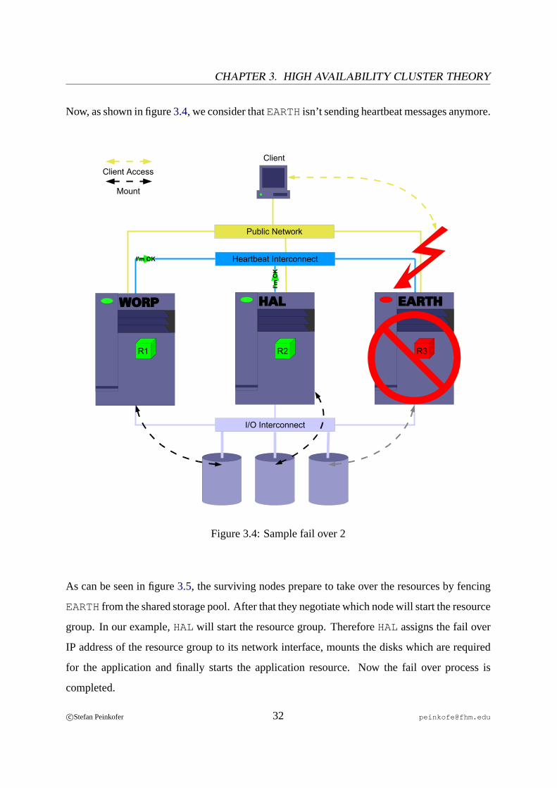
Now, as shown in figure3.4, we consider thatEARTHisn’t sending heartbeat messages anymore.
Heartbeat Interconnect
WORP HAL EARTH
R1 R2 R3
I'm OK
I'm O
K
I/O Interconnect
Mount
Public Network
ClientClient Access
Figure 3.4: Sample fail over 2
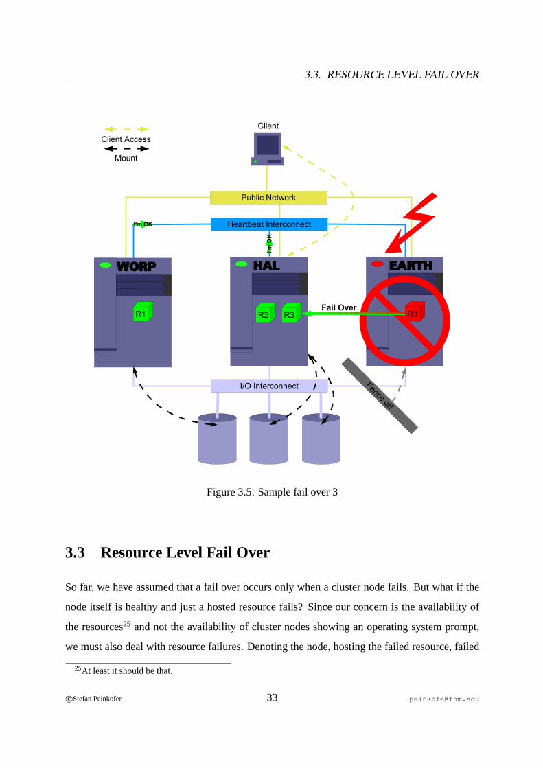
As can be seen in figure3.5, the surviving nodes prepare to take over the resources by fencing
EARTHfrom the shared storage pool. After that they negotiate which node will start the resource
group. In our example,HALwill start the resource group. ThereforeHALassigns the fail over
IP address of the resource group to its network interface, mounts the disks which are required
for the application and finally starts the application resource. Now the fail over process is
completed.
c©Stefan Peinkofer 32 [email protected]
3.3. RESOURCE LEVEL FAIL OVER
Heartbeat Interconnect
WORP HAL EARTH
R1 R3
I'm OK
I'm O
K
I/O Interconnect
Mount
Public Network
ClientClient Access
Fence off
R2 R3 Fail Over
Figure 3.5: Sample fail over 3
3.3 Resource Level Fail Over
So far, we have assumed that a fail over occurs only when a cluster node fails. But what if the
node itself is healthy and just a hosted resource fails? Since our concern is the availability of
the resources25 and not the availability of cluster nodes showing an operating system prompt,
we must also deal with resource failures. Denoting the node, hosting the failed resource, failed
25At least it should be that.
c©Stefan Peinkofer 33 [email protected]
CHAPTER 3. HIGH AVAILABILITY CLUSTER THEORY
and initiating a node level fail over would do the job but it’s obviously not the best solution. The
node may be hosting many other resources which operate just fine. The best solution would be
to fail over just the resource group which contains the failed resource.
As we have discussed in chapter3.2.3on page21 resource agents can monitor the health of
a resource. So to observe the state of the resources, the cluster system will ask the resource
agent from time to time to perform the monitor operation. When a resource agent returns a neg-
ative result, the cluster system will either immediately initiate a fail over of the resource group
or it will first try to restart the resource locally and just fail over if the resource still fails. To fail
over, the cluster system will stop the failed resource and all resources which belong to the same
resource group by requesting that the appropriate resource agents perform the stop operation.
After all resource are stopped successfully, the cluster system will ask the other nodes in the
cluster to take over the resource group.
Since the node, which hosted the failed resource originally, is still a reputable member of the
cluster, the node taking over must not fence the node. It is up to the resource agents to stop
the resources reliably, to prevent multiple instances of the same resource from running. The
resource agent must make sure that the resource was stopped successfully and return an error if
it failed in doing so. How the cluster system reacts to such an error is dependent on the cluster
system or the configuration. Basically there are two options: either leave the resource alone and
call for human intervention or stop the resource by removing the node from the cluster mem-
bership and then performing a node level fail over. Stopping the resource is implicit in this case
because the node is fenced off during the node level fail over.
Another problem arises if a resource fails because of a failure which will cause the resource
to fail on every node, it will be taken over. Typically this is caused by shared data failures or
application configuration mistakes. In such a case the resource group will be failed over from
node to node until the resource can be started successfully again. Theseping-pong fail overs
are usually not harmful, but they are not desirable because they are typically caused by failures
c©Stefan Peinkofer 34 [email protected]

3.4. PROBLEMS TO ADDRESS
which require human intervention. In other words, ping-pong fail overs provide no benefit, so
most cluster systems will give up failing over a resource group if it failed to startN times on
every cluster member.
3.4 Problems to Address
In the fail over chapter above we left some problems which might occur on a high availability
cluster unaddressed. In this chapter we want to look at these problems and discuss how a cluster
system can deal with them.
3.4.1 Split Brain
Thesplit brain syndromeor cluster partitioningis a common failure scenario in clusters. It is
usually caused by a failure of all available heartbeat paths between one or more cluster nodes.
In such a scenario a working cluster is divided into two or more independentcluster partitions,
each assuming it has to take over the resources of the other partition(s). It is very hard to predict
what will happen in such a case since each partition will try to fence the other partitions off. In
the best case scenario, a single partition will manage to fence all the other partitions off before
they can do it and therefore will survive. In the worst and more likely case, each partition
will fence the other partitions off simultaneously and therefore no partition will survive. How
this can happen can be easily understood in a STOMITH environment, in which the partitions
simultaneously trigger the reboot of the other partitions. In a SCSI reservation environment it’s
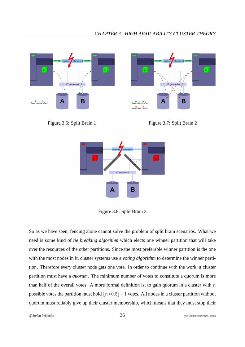
not so obvious but it can occur too. Like figure3.6 shows, for example in a two-node cluster
with two shared disksA andB, node one reservesA and thenB and node two reservesB and
thenA. As shown in figure3.7 this procedure leads to a deadlock and because both nodes will
get a SCSI reservation error when reserving the second disk, both nodes will stop working.
c©Stefan Peinkofer 35 [email protected]
CHAPTER 3. HIGH AVAILABILITY CLUSTER THEORY
BA
R1 R2
I'm OK I'm OK
Reservation in effect
I/O Interconnect
Heartbeat Interconnect
Figure 3.6: Split Brain 1
BA
R1 R2
Reservation in effect
I/O Interconnect
Reservation conflict
I'm OK I'm OKHeartbeat Interconnect
Figure 3.7: Split Brain 2
R1 R2Fence offFence
off
BA
I/O Interconnect
Heartbeat Interconnect
Figure 3.8: Split Brain 3
So as we have seen, fencing alone cannot solve the problem of split brain scenarios. What we
need is some kind oftie breaking algorithmwhich elects one winner partition that will take
over the resources of the other partitions. Since the most preferable winner partition is the one
with the most nodes in it, cluster systems use avoting algorithmto determine the winner parti-
tion. Therefore every cluster node gets one vote. In order to continue with the work, a cluster
partition must have aquorum. The minimum number of votes to constitute a quorum is more
than half of the overall votes. A more formal definition is, to gain quorum in a cluster withn
possible votes the partition must holdbn∗0.5c+1 votes. All nodes in a cluster partition without
quorum must reliably give up their cluster membership, which means that they must stop their
c©Stefan Peinkofer 36 [email protected]
3.4. PROBLEMS TO ADDRESS
resources and must not carry out any fencing operation, so the winner partition can fence the
nodes in the other partitions and take over their resources.
Assigning votes only to cluster nodes is not sufficient in two-node cluster configurations be-
cause in a split brain situation or if one node dies, no partition can constitute a quorum and
therefore every node will give up its cluster membership. To prevent this we must use an ad-
ditional vote which will deliver quorum to one of the two partitions. A common approach to
deliver this additional vote is the use of aquorum disk. A quorum disk must be shared between
the two nodes and delivers one additional vote to the cluster. Now when the nodes lose all
heartbeat paths, they first try to acquire the vote of the quorum disk by an atomictest and set
method, like the SCSI-2 or SCSI-3 reservation feature or by using some kind of synchronisa-
tion algorithm which eliminates the possibility of both nodes thinking they have acquired the
quorum disk. Using this method, only one node will gain quorum and therefore can continue as
a viable cluster.
Although a quorum disk is not required in a cluster of more than two nodes, its deployment
is advisable to prevent unnecessary unavailability if none of the cluster partitions can constitute
quorum – for example when a four-node cluster splits into two partitions, each holds two votes,
or when two of the four nodes die. The optimal quorum disk configuration in a2+ node cluster
is to share the quorum disk among all nodes and assign it a vote ofN−1 whereN is the number
of cluster nodes. So the minimal votes needed to gain quorum isN . Since the quorum disk has
a vote ofN − 1 a single node in the cluster can gain quorum. This provides the advantage of
system availability, even if all but one node fails. However this has the disadvantage that when
a cluster is partitioned, the partition with fewer nodes could gain quorum if it wins the race
to the quorum disk. To avoid this, the partition which contains the most nodes must be given
a head start. An easy and reliable way to achieve this is that every partition waitsS seconds
before it tries to acquire the quorum disk, whereasS is the number of nodes which are not in
the partition. This approach will reliably deliver quorum to the partition with the most nodes.
c©Stefan Peinkofer 37 [email protected]
CHAPTER 3. HIGH AVAILABILITY CLUSTER THEORY
A few cluster systems don’t support the concept of quorum devices. These systems solve the
problem of two-node clusters by asserting that even a single-node cluster partition has quorum,
and therefore has the permission to fence the other node off. To prevent both nodes from getting
fenced at the same time, they use a random time delay before the fencing operation is carried
out. However, this approach may cause the nodes to enter afence loop. Fence loops are dis-
cussed in chapter3.4.2on page38.
We also have to discuss the relationship between quorum and fencing. At first glance, it seems
that through the use of the quorum algorithm, the fencing step becomes dispensable. For the
majority of cluster systems this is not true. Most cluster systems are built on top of the operat-
ing system as a set of user processes. If a cluster is partitioned, the nodes in one partition don’t
know anything about the state of the nodes in the other partition. Maybe the cluster software
itself failed and is no longer able to stop the resources, or maybe the operating system is caus-
ing errors on the shared storage even though the resources have been stopped. So the nodes
in the quorum partition cannot rely on the convention that a node without quorum will stop
its resources and the I/O operations on the shared disks. So for these cluster systems, quorum
defineswho should proceedand successful accomplishment of the fencing operations defines
that it is safe to proceed.
It is worth mentioning that some cluster systems which are tightly integrated with the oper-
ating system, like theVMScluster, don’t need the fencing step. The loss of quorum causes the
operating system to suspend all I/O operations and processes. On these cluster systems, having
quorum also means it’s safe to proceed. Of course this requires the quorum algorithm itself and
the “loss of quorum code“ to work reliably under all circumstances.
3.4.2 Fencing Loops
As already discussed in chapter3.4.1 on page37, some cluster systems ignore quorum in
two-node cluster configurations. If a node is not shut down or halted, but rebooted as an ef-
fect of being fenced, the nodes will enter a fencing loop if the fencing was an effect of a split
c©Stefan Peinkofer 38 [email protected]
3.4. PROBLEMS TO ADDRESS
brain syndrome. In a fencing loop, the fenced nodeA will reboot and therefore try to join the
cluster, once it’s up again. The cluster system onA will notice that it cannot reach the other
nodeB and fence nodeB to make sure that it is safe to incarnate a new cluster. After nodeB
has rebooted, it cannot reach nodeA and will fence nodeA and so on. The nodes will continue
with this behavior as long as they are not able to exchange heartbeat messages or until human
intervention occurs.
If a cluster system ignores quorum, it is not possible to prevent the nodes from entering a
fencing loop. This fact has to be kept in mind when designing a cluster which uses such a
cluster system. The only thing that can be done to alleviate the problem is to use any available
interconnect between the nodes to exchange heartbeat messages, so the likelihood of a split
brain scenario is minimized.
The reason cluster software developers may choose to fence a node by rebooting and not halting
the node is that it is likely that the failure can be removed by rebooting the node.
3.4.3 Amnesia
Amnesiais a failure mode in which a cluster is incarnated with outdated configuration infor-
mation. Amnesia can occur if the administrator does some reconfiguration on the cluster, like
adding resources, while one or more nodes are down. If one of the down nodes is started and
joins the cluster again it receives the configuration updates from the other nodes. However, if
the administrator brings down the cluster after he does the reconfiguration and then starts one
or more of the nodes which were down during the reconfiguration, they will form a cluster that
is using the outdated configuration.26 Some cluster systems prevent this by leaving the names
of the nodes which were members of the last cluster incarnation on a shared storage medium.
Before a node incarnates a new cluster it checks to determine whether it was part of the last
incarnation and if not, it waits until a member of the last incarnation comes up.27 Some other
26[ELLING] Page 3027[ELLING] Pages 107 - 108
c©Stefan Peinkofer 39 [email protected]
CHAPTER 3. HIGH AVAILABILITY CLUSTER THEORY
cluster systems leave the task of avoiding amnesia to the system administrator.
3.4.4 Data Corruption
Even if we could assume that a healthy node doesn’t corrupt the data it is using, we cannot
assume the same of a failed node. Maybe it failed while it was writing a file to disk, for ex-
ample. The cluster software ensures that data is not corrupted by uncoordinated simultaneous
data access of more than one node. As we have seen, data corruption is not only caused by
this failure scenario. Even the fencing operation could cause data corruption when it fences
a node in the middle of an I/O operation. So the node which takes over the data must accept
that the data may got corrupted and it needs some strategies to recover from that data corruption.
To deal with data corruption, we can basically use two different approaches. The first one
is to use some kind ofanalyzing and repairprogram like thefsckcommand for UNIX file sys-
tems. Those programs will check to determine whether the data got corrupted. If so, they will
try to recover it by bringing the data back to a usable state, somehow. However, these tools are
usually very time consuming because they have to “guess“ which parts of the data are corrupted
and how to recover them. Therefore it would be useful if the corrupted data could tell the taking
over node what the problem is and how it can be fixed. The key to this approach aretransac-
tions. Among other things, they providedurability andatomicity. This means that a transaction
which has completed will survive a system failure and that a transaction which could not be
completed can be undone. This is achieved by maintaining alog file on disk which contains all
the changes that were made to the data and a property which indicates whether the change was
already successfully applied or not. To get a better understanding of transactions, let’s briefly
look at the steps of an example transaction:28
1. Update request “Change valueA to 5“ comes in
2. Look up the current value ofA (e.g. 1) and append a record to the log file containing
“Changed valueA from 1 to 5“
28[PFISTER] Pages 408 - 409
c©Stefan Peinkofer 40 [email protected]
3.5. DATA SHARING
3. Make sure that the log record is written to disk
4. Change valueA to 5 on disk
5. Note in the log file record that the update was applied
6. Make sure that the log record is written to disk
7. Return success to the requestor
When a node takes over the data of another node, it just has to look at the log file and undo the
changes which aren’t marked as applied yet. It is worth mentioning that this algorithm is even
tolerant against corruption of the log file. For example if step 3 is not carried out completely,
and therefore, the log file is corrupted, the corrupted log file record can be ignored because no
changes have been made to the data yet.
Almost any modern operating system uses transactional based file systems because of the great
advantages of transactions, compared to the analyze and repair tools. These file systems are
usually termed asjournalizingor loggingfile systems.
3.5 Data Sharing
As mentioned in chapter3.2.5.3on page25 the use of shared storage devices provides the op-
portunity to let multiple nodes access the data on the shared storage at the same time. Of course,
what benefit this provides to high availability clusters is a legitimate question, since a resource
can only run on one node at a time. In fact, there are not so many scenarios in which this is
beneficial. Generally speaking, it’s only valuable if a set of applications which normally has to
run on a single node in order to access a common set of data can be distributed among two or
more nodes to distribute the workload.
For example if we want to build a file server cluster which provides the same data to UNIX
and Windows users, we have to use two different file serving applications, namely NFS and
c©Stefan Peinkofer 41 [email protected]
CHAPTER 3. HIGH AVAILABILITY CLUSTER THEORY
Samba. Without sharing the data between the cluster nodes, both resources have to be located
on the same node. With sharing the data, we can distribute the load among two nodes by run-
ning NFS on one and Samba on another node.
Unfortunately, standard file systems are not able to be mounted more than once at a time. To
understand why this restriction is in effect, we must take a look at how these file systems operate.
Every file system containsdataandmeta data. Data is the actual content of the files and meta
data contains the management information of the file system, like
• which disk blocks belong to which file,
• which disk blocks are free,
• which directories exist and which files are in them.
If a file system is mounted, parts of the file system data and meta data are cached in the main
memory of the computer which has mounted the file system. If a cached part of the file system
is modified, the changes are applied to the disk and to the cache. If a cached part of the file
system is read, the information is retrieved only from main memory, since this is many times
faster than retrieving it from disk.29 In addition the operating system on the computer which
has mounted the file system assumes that it has exclusive access to the file system. Therefore
it does not need to pay attention to file system modifications which are carried out by another
computer which has mounted the file system at the same time, since this is forbidden.
In order to be able to mount a file system on more than one node simultaneously, four main
problems have to be solved.
• Meta data cache inconsistency- Changes of the meta data, which are carried out by one
node, are not recognized by the other nodes. For example, if nodeA creates a new file
X and allocates disk block1 for it, it will update the file system’s free block list in its
29[STALKER]
c©Stefan Peinkofer 42 [email protected]

3.5. DATA SHARING
local memory as well as on the disk, but nodeB is unaware of this update. Now if nodeB
creates a new fileY, it will allocate disk block1, too, since the cached free block list on
B still indicates that block1 is not yet allocated.30
• Meta data inconsistency- The file system assumes that it has exclusive access to the meta
data and therefore does not need anylocking mechanismfor that. Meta data changes are
not atomic operations but a series of I/O operations. If two nodes perform an update of
the same meta data item at the same time, the meta data item on the disk can become
corrupted.
• Data cache inconsistency- A once written or read block will remain in thefile system
cacheof the node for some time. If a block is written by a node while it is cached by
another node, the file system cache of that node becomes inconsistent. For example, node
A reads block1 from disk, which contains the value1000. Now when nodeB changes the
value of block1 to 2000, the cache of nodeA becomes outdated. But sinceA is not aware
of that, it will pass the value1000 back to the processes which request the value of block
1 until the file system cache entry expires.31
• Data inconsistency- If a process locks a file for exclusive access, this lock is just in effect
on the node on which the process runs. Therefore a process on another node could gain a
lock for the same file at the same time. This can lead to data inconsistency. For example,
let nodeA lock file X and read a value, say4000, from it. Now nodeB locks the file too
and reads the same value. NodeA adds1000 to the value andB adds2000 to the value.
After that nodeA updates the value on the disk and then nodeB updates the value too. So
the new value on disk is6000 but it’s supposed to be7000.
The special file systems which are able to deal with these problems are usually termed ascluster
file systemsorSAN file systems. In the following sections we will look at the differences between
cluster and SAN file systems as well as the different design approaches of these file systems.
30[STALKER]31[STALKER]
c©Stefan Peinkofer 43 [email protected]
CHAPTER 3. HIGH AVAILABILITY CLUSTER THEORY
3.5.1 Cluster File System vs. SAN File System
Beforestorage area networkswere invented, using a cluster file system was the only possibility
to share a file system on the I/O interconnect level. With the emergence of storage area networks
as an industry standard shared I/O interconnect, customers wanted to be able to share their file
systems not only within a cluster but also among virtually any node which is attached to the
SAN. So companies like IBM, SUN and many more began to developstand alone shared file
systems, which are termed SAN file systems.
Actually it is very hard to set a clear boundary between cluster and SAN file systems. One
approach is that a cluster file system is a shared file system which cannot be deployed without
an appropriate cluster system because it makes use of functions the cluster system provides. On
the other hand, some shared file systems32 don’t rely on a cluster system but behave exactly like
a file system which does. They simply implement the needed cluster concepts themselves. So a
better definition may be that a cluster file system uses the concepts of cluster membership and
quorum in order to determine which hosts are allowed to access the file system whereas SAN
file systems don’t. If we use this definition, we can point out further differences between cluster
and SAN file systems:
1. SAN file systems must deploy acentral file system coordinatorwhich manages the file
system accesses. To perform a file system operation, a node has to get the permission of
the file system coordinator first. If the node fails to contact the coordinator it must not
write to the file system. In contrast, cluster file systems can, but do not have to, deploy
such a coordinator since every node is allowed to access the file system, as long as it is a
member of the quorum partition, a fact which hosts on a SAN file system are not aware
of.
2. SAN file systems are not highly available by default since the file system coordinator is a
single point of failure. However, the coordinator task can usually be manually failed over
to an alternate host. Cluster file systems which use a central file system coordinator will
32Like theLustrefile system.
c©Stefan Peinkofer 44 [email protected]
3.5. DATA SHARING
automatically ensure that the file system coordinator task is always done by a member of
the quorum partition.
3. SAN file systems can be deployed in a cluster as a cluster file system33. But making
the file system highly available as a SAN file system, meaning that nodes outside of
the cluster can access the file system too, can be difficult if the cluster system uses SCSI
reservation for fencing.34 This is because the cluster software will ensure that only cluster
members can access the disks, so non-cluster members are fenced by default.
4. Cluster file systems can usually only be shared between nodes which run the same op-
erating system type. SAN file systems can typically be shared between more than one
operating system type.
3.5.2 Types of Shared File Systems
This chapter discusses the different approaches to how file systems can be shared between hosts.
The first two methods discussed deal with file systems which really share access to the physical
disks, whereas the third one deals with a virtual method of disk sharing, sometimes termedI/O
shipping.
3.5.2.1 Asymmetric Shared File Systems
On asymmetric sharedfile systems, every node is allowed to access the file system data, but
only one is allowed to access the meta data. This node is calledmeta data serverwhereas the
other nodes are calledmeta data clients. To access meta data, all meta data clients must request
this from the meta data server. So if a meta data client wishes to create a file, for example, it
advises the meta data server to create it and the meta data server returns the disk block address
which it has allocated for the file to the meta data client.35 Since all meta data operations are
coordinated by a single instance,meta data consistencyis assured implicitly.
33The use of quorum and membership is implicit in this case through the cluster software.34Therefore some vendors like IBM offer special appliances which provide a highly available file system direc-
tor.35[KRAMER]
c©Stefan Peinkofer 45 [email protected]
CHAPTER 3. HIGH AVAILABILITY CLUSTER THEORY
3.5.2.2 Symmetric Shared File Systems
Onsymmetric sharedfile systems, every node is allowed to access not only the file system data
but also the meta data directly. In order to prevent meta data inconsistency, it has to be ensured
that only one host can modify a specific meta data item at a time, and that no host is able to
read a meta data item which is currently being changed by another node. This functionality is
provided by a file system widelock manager.
3.5.2.3 Proxy File Systems
On proxiedfile systems, the disks are not physically shared. Instead, one node mounts the file
system physically and shares the file system with the other nodes over a network connection.
The node which has mounted the file system physically is calledfile system proxy server; the
other nodes are calledfile system proxy clients. In principle a proxy file system works like a
network file system like NFS or CIFS(CommonInternetFile System). The difference is that
network file systems share the files which are located on some type of file system, whereas
proxy file systems directly share the file system on which the files are located. For example,
let’s consider that a server exports an UFS file system over NFS and over a cluster proxy file
system. The network file system clients mount the exported file system as NFS file system but
the cluster nodes mount the exported file system directly as UFS.
If an application on a file system proxy client requests a file system operation, the kernel reroutes
it over the network connection to the kernel on the file system proxy server, which carries out
the actual I/O operation and returns the result to the requesting node.36
Usually, this type of file system is only deployed in clusters since in non-cluster environments
network file systems are widely accepted as a standard for sharing data over the network. Since
only one instance controls access to the whole file system,dataandmeta data consistencyare
implicit.
36[ARPACI] Pages 8 - 9
c©Stefan Peinkofer 46 [email protected]
3.5. DATA SHARING
3.5.3 Lock Management
As we have seen, file locks and eventually even locks on meta data items must be maintained
file system wide so thatdataandmeta data inconsistencyis avoided. To implement locking in
a distributed environment, there are two basic approaches. The first is deploying a central lock
server and the second is distributing the lock server tasks among the nodes. The basic problems
a lock manager has to deal with are deadlock detection, releasing locks of failed nodes and
recovering the file system locks if the/a lock manager has failed.
The concepts ofcentralized lock managementare similar to the meta data server concept of
asymmetric shared file systems. The process of requesting a lock is the same as requesting a
meta data operation. Since all lock management operations are done on a single node, dead-
lock detection is no problem because ordinary algorithms can be used for this. Centralized lock
management can be used by a cluster file system but it must be used by a SAN file system, since
the central lock manager coordinates the file system accesses.
With distributed lock management, every node can be a lock server for a well defined, not over-
lapping subset of resources. For example nodeA is responsible for files beginning withA-M and
nodeB is responsible for files beginning withN-Z 37. The main advantage of this method is that
the computing overhead for lock management can be distributed among all nodes.38 The main
disadvantage is that deadlock detection is much more complex and slower, since a distributed
algorithm has to be used.
How the lock manager deals with locks of failed clients depends on whether it is used by a
cluster file system or not. On a cluster file system, the lock manager knows when a node fails
and therefore can safely release all locks of the failed member.39 On a SAN file system the lock
server doesn’t know if a client has failed, so another strategy must be used. One possible solu-
37Of course this is an abstract example.38[KRONEN] Pages 140 - 14139[KRONEN] Page 142
c©Stefan Peinkofer 47 [email protected]
CHAPTER 3. HIGH AVAILABILITY CLUSTER THEORY
tion is to grant locks only for a specific period of time, calledlease time. If a client needs a lock
for longer than the lease time, it has to re-request the lock before the lock times out. If the client
is not able to contact the lock server to request more time, it must suspend all I/O operations
until it can contact the lock server again. Assuming this works reliably, the lock manager can
safely release all locks for which the lease time has expired.
To recover the lock state in case of a lock manager failure, two different strategies can be
used. The first one is to keep a permanent copy of the lock information on a disk so if a lock
manager fails, another node can read the last lock state and take over the log manager function.
Of course, this method performs not very well, since a hard disk access is required for each lock
operation. The other method is that every node keeps a list of the locks it currently owns. To
recover the lock state, the new lock manager asks all nodes to tell it what locks are in effect on
the system.40
3.5.4 Cache consistency
The final thing we have to discuss is how the data and meta data caches can be kept synchro-
nized on all nodes. For this purpose basically three different approaches can be deployed.
The first and easiest method is calledread-modify-write. The method is so easy because read
means reading from disk, so no caching is done at all. Of course a file system which uses this
method does not perform very well. But it may be suitable for solving the meta data cache
problem in symmetric shared file systems41.
The second concept isactive cache invalidation. If a node wants to modify an item on the
disk, it notifies all other nodes about that. The notified nodes will look in their local cache if it
contains the announced item and, if so, they will remove it from the cache or mark the cache
40[PFISTER] Pages 418 - 41941[YOSHITAKE] Page 3
c©Stefan Peinkofer 48 [email protected]

3.5. DATA SHARING
entry as invalid42.
The last method ispassive cache invalidation. It’s based on maintaining a version number
for each file system item. If a node modifies the item, the version number gets incremented.
If another node wants to read the item, it looks first at the version number of the item on disk
and compares it with the version number of the item in the cache. If they match, the node can
use the cached version; if not, it has to re-read it from the disk. Of course, having a version
number for every disk block, for example, would be too large an overhead. Because of this,
version numbers are usually assigned at the level of lockable resources. For example if a lock
manager allows file level locks, every file gets a version number. The coupling of passive cache
invalidation and locking adds another advantage. Instead of writing and reading the version
numbers to/from the disk by each node individually, the numbers can be maintained by the lock
manager. So if a node requests a lock, the version number of the locked item is passed to the
node together with the lock.43
42[KRONEN] Page 14243[KRONEN] Page 142
c©Stefan Peinkofer 49 [email protected]
Chapter 4
Designing for High Availability
After we have seen how high availability clusters work in general, we have to look at some ba-
sic design considerations, which have to be taken in account when planning a high availability
cluster solution. The chapter is divided into three main areas of design considerations. The
first area deals with general high-level design considerations which are usually implemented
together with the IT management. The second area is about planning the hardware layout of the
cluster system and the environment in which the high availability system will be deployed. The
third area is dedicated to the various software components involved in a cluster system.
Since the concrete design of a high availability cluster solution depends mainly on the hard-
ware and software components used, the available environment and the customer requirements,
we can only discuss the general design issues here. We will look at two concrete designs in the
sample implementations in chapters6 and7. This chapter also addresses design issues which
are not directly related to cluster systems but deal with high availability in general. It’s worth
mentioning that if someone plans to deploy a high availability cluster system in a poorly avail-
able environment, it’s often better to use a non-clustered system and spend the saved money on
improving the availability of the environment first.
The design recommendations and examples in the following chapters should be understood
as best case solutions to achieve a maximum of availability. In a real-life scenario, the decision
50
4.1. SYSTEM MANAGEMENT AND ORGANIZATIONAL ISSUES
for or against a particular recommendation is the result of a cost/risk analysis. Also it is possible
to implement particular recommendations only to certain extents.
4.1 System Management and Organizational Issues
High availability cluster systems provide a framework to increase the availability of IT services.
However, achieving real high availability requires more than just two servers and a cluster
software. In order to build, deploy and maintain these systems successfully, the IT management
must provide a basic framework which defines clear processes for system management and
implements some organizational rules.
4.1.1 Requirements
The first task in the design process is to identify and record the requirements of the high avail-
ability cluster system. The “requirements document“ contains high level information which
will be needed in the subsequent design process. The document is the result of an requirements
engineering process which can contain, but is not limited to, the following steps:
• Create an abstract description of the project, together with the management.
• Identify the services the system should provide and the users of the various services.
• Determine the individual availability and performance requirements of the different ser-
vices.
• Identify dependencies between services hosted by the system and services hosted by ex-
ternal systems.
• Negotiate service level agreements like service call response time and maximum down-
time with the various vendors of the system components.
• Work out a timeline for system development.1
1[ELLING] Page 198
c©Stefan Peinkofer 51 [email protected]
CHAPTER 4. DESIGNING FOR HIGH AVAILABILITY
4.1.2 Personnel
As mentioned before, high availability cannot be achieved by simply buying an expensive high
availability system. One of the key factors to high availability is the staff which administers the
system. Therefore we have to take some considerations about the personnel into account.
The first thing we have to do is to remove personnel single points of failures. For example,
when a high availability system is managed by only one system administrator, this person is a
SPOF. If he leaves the company or goes on holidays for a week, the other administrators may
not be able to operate the system in the appropriate manner. The first step in removing the SPOF
is creating a comprehensive documentation of the system design, including network topology,
hardware diagrams, deployed applications, inter-system dependencies and so on. In addition to
that a troubleshooting guide, which contains advice for various failure scenarios and hints for
problem tracking, must be created. The troubleshooting guide should also contain all problems
and their solutions which already occurred during the system deployment.2
Having system documentation is mandatory, but it is not sufficient. If a system fails and the
primary system administrator is unavailable, the backup administrator usually does not have the
time to read through the system documentation. Therefore the backup administrators have to
be trained on the system design, the handling of the various hardware and software components
and basic system troubleshooting techniques, before the system goes into production use. An
additional approach could be that a system is designed and maintained by a team of administra-
tors, in the first place.3 What has to be kept in mind is that documentation and training cannot
replace experience. Some managers think that a trained administrator has the same skills as
an administrator who has maintained a system for years. Since this is not the case, unless the
system is very simple, personnel turnover of such highly experienced people should be avoided,
if at all possible.4
2[MARCUS] Pages 289 - 2913[ELLING] Page 1994[MARCUS] Pages 291 - 293
c©Stefan Peinkofer 52 [email protected]

4.1. SYSTEM MANAGEMENT AND ORGANIZATIONAL ISSUES
To achieve real high availability, not only systems, but also the administrators, have to be highly
available. Since systems not only fail during business hours5, it must be ensured that someone
from the IT staff can be notified about failures, 24 hours a day, 7 days a week and 52 weeks a
year. The primary solution for this are pagers or mobile phones. However, this doesn’t guar-
antee that the person is reachable all the time, so this is another single point of failure which
must be removed. To solve this problem, we must define anescalation process. This process
defines which person should be notified first and which person should be notified next, in case
the first person does not respond within a specific time. Of course, the notification is useless
if the administrators cannot access the system during non-business hours. They need at least
physical access to the system around the clock. A better solution is to provide the administra-
tors additionally with remote access to the systems. This can significantly speed up the failure
response process, because the time for getting dressed and driving to the office building can be
saved. However, since some tasks can only be performed with physical access to the system,
remote access can only be an add-on for physical access.6
4.1.3 Security
Security leaks and weakness can doubtless lead to unavailability if someone in bad faith exploits
them to access the systems. But even someone in good faith could cause system downtime be-
cause of a security weakness. Therefore the systems must be protected from unauthorized
access from both outside and inside the company. Some common methods for this arefirewalls,
to protect the systems against attackers from the Internet,intrusion detection systems, to alert
of attacks and passwords that are hard to guess and are really kept secret. Additionally, as
few people as possible should be authorized to have administrative access to the system. For
example, developers should usually have their own development environment, but under some
circumstances, developers may also need access to the productive systems. Giving them admin-
istrative access to the production system when unprivileged access to the system would suffice
5In fact it seems that they fail more often during non-business hours.6[MARCUS] Pages 294 - 295
c©Stefan Peinkofer 53 [email protected]
CHAPTER 4. DESIGNING FOR HIGH AVAILABILITY
must not be allowed since privileged users have far more possibilities to make a system unavail-
able by accident than unprivileged users. If the specific task of the developer requires special
privileges, he must also not be given full administrative access but his unprivileged account has
to be assigned only the privileges which are necessary to let him carry out the specific task.7
Another aspect of security is that physical access to the system must be limited to authorized
personel.8 This is needed to protect against the famous cleaning lady pulling the power plug of
the server to plug in the vacuum cleaner and on the other hand from wilful sabotage by an angry
employee for example.
4.1.4 Maintenance and Modifications
Like any other computer system, high availability clusters require software and hardware main-
tenance and modifications from time to time. The advantage of high availability clusters is that
most of the tasks can be done without putting the whole cluster out of service. A common strat-
egy is to bring one node out of cluster operation, perform the maintenance tasks on that node,
check and see whether the maintenance was successful, bring the node back in the cluster and
perform maintenance on the next node.9 However, this means that the services are unavailable
for a short time period because the resources, hosted by the node on which the maintenance
should be applied, have to be failed over. Therefore, performing maintenance tasks in high
workload times, in which the short unavailability would affect many users, should be avoided.
In addition to that, a few maintenance tasks even require the shutdown of the whole cluster. Not
performing maintenance tasks which require that a node or the whole cluster has to be put out
of operation at all is no option, since the likelihood of unplanned downtime increases over the
time when a system is not properly maintained. So we should appoint periodicalmaintenance
7During my practice term, a customer called us to restore one of their cluster nodes. A developer wrote a “clean
up“ script which should delete all files in a particular directory and the sub directories, which are older than 30
days. The problem was that the script did not change in the directory to clean up and she scheduled the task in
the crontab of root. So in the evening, the script began to run as root, in the home directory of root, which is / on
Solaris.8[MARCUS] Pages 287 - 2889[MARCUS] Page 270
c©Stefan Peinkofer 54 [email protected]

4.1. SYSTEM MANAGEMENT AND ORGANIZATIONAL ISSUES
windows, preferable in times when the system does not have to be available or at least in low
workload times. These windows are used to perform common maintenance tasks like software
and firmware updates, adding or removing hardware, installing new applications, creating new
cluster resources, and so on.10
Unfortunately, maintenance and modification tasks are critical even if they are performed during
a maintenance window. For example the maintenance could take longer than the maintenance
window or something may break because of the performed task. Another “dirty trick“ of main-
tenance tasks is that sometimes they seem to work fine at first, but cause a system failure many
weeks after the actual maintenance task is carried out. To minimize the likelihood of mainte-
nance tasks affecting availability, we must define and follow some guidelines.
• Plan for maintenance - Every maintenance task has to be well planned in the first
place. Reading documentation and creating step-by-step guidelines of the various tasks
is mandatory. Since something could go wrong during the maintenance, identifying the
worst case scenarios and planning for their occurrence is also vital. In addition to that, a
fallback plan to roll back the changes, in case the changes do not work as expected or the
maintenance task cannot be finished during the maintenance window, has to be prepared.
• Document all changes- Every maintenance task has to be documented in arun bookor
another appropriate place like achange management system. Things to document, among
the usual things like date, time and name of the person who performed the maintenance,
are the purpose of the task, what files or hardware items were changed and how to undo
the changes. In addition to the run book, it’s a good idea to note changes in configurations
files with the same information as in the run book.
• Make all changes permanent- Especially in stressful times, administrators seem to
take the path of least resistance. In this case, it can happen that changes are applied
only in a non-permanent way. For example adding a network route or an IP address,
by the usual commandsroute and ifconfig lasts only until the next reboot unless
10[STOCK] Page 20
c©Stefan Peinkofer 55 [email protected]
CHAPTER 4. DESIGNING FOR HIGH AVAILABILITY
they are made permanent by changing the appropriate configurations files. The effect
after the next reboot, which is usually carried out some time later, most likely within
a maintenance window in which several maintenance tasks are carried out, is that the
non-permanent modifications have vanished and the users will complain about it. Since
the actual modifications were made some time ago and a system maintenance was carried
out a few minutes or hours ago, it is usually the beginning of a long fault isolation night
since everybody thinks in the first place that the problem was caused by the recent system
maintenance and not by a non-permanent modification made some days or weeks ago.
• Apply changes one after another- Applying more than one change at a time makes it
very hard to track the problem if something goes wrong. Administrators should apply
only one change at a time and after that make sure that everything still works as expected.
Rebooting after the change is also a good idea, since some changes only take full effect
after a reboot. After that, the next change can be applied.11
Another point to consider, in conjunction with maintenance, are spare parts. Keeping a spare
parts inventory can help to decrease the mean time to repair. In order to get the most benefit
of such an inventory, from the administrator’s as well as form the manager’s point of view,
some rules have to be followed. The first thing is to decide which spare parts will be stocked.
This should be at least the parts which fail the most, like disks or power supplies for example
and the parts which are hard to get, meaning they have a long delivery period or are offered
only by a few suppliers. Another point is that it must be ensured that the parts in stock are
working. So it’s mandatory to test new parts before they are put into the inventory. In addition
to that, authorized personnel must have access to the spare parts around the clock and access of
unauthorized personnel must be prevented.12
11[MARCUS] Pages 270 - 27112[MARCUS] Page 273
c©Stefan Peinkofer 56 [email protected]

4.1. SYSTEM MANAGEMENT AND ORGANIZATIONAL ISSUES
4.1.5 Testing
Every change which is planned to be applied to a productive system should first be tested in an
insular test environment. This is especially important for patches and software updates which
should be applied and for new software which should be installed. An ideal test environment
would be an identical copy of the productive system. In this case, the test environment can
be used as spare part inventory, too.13 But mostly, the test environment is a shrunken copy
with smaller servers and storage. Often a company deploys more than one nearly identical
productive system so that only one test environment is needed. Though the costs of such a
test environment are not negligible, it provides various benefits. Applying broken patches and
software on the productive systems, and therefore unplanned downtime, can be avoided. Main-
tenance tasks can be tested with no risk and performing the maintenance task on the productive
system can be done faster, since the administrators are already familiar with the specific tasks.
The test environment can also be used for training and to gain experience. In addition to that
application developers can use the test environment for developing and testing new applications.
Another aspect of testing is the regular functional checking of the productive systems. For
this purpose, common failure scenarios are initiated while monitoring the systems if they re-
spond to the failure in the desired way. But not only the cluster system itself has to be tested.
Infrastructure services, like the network, air conditioning or uninterruptible power supplies have
to be tested regularly as well.14
4.1.6 Backup
It should be self-evident that all local and shared data of the cluster has to be backed up some-
how. In addition to proper backup media handling, some additional guidelines have to be fol-
lowed to get the maximum benefit from a backup system.
1. Disk mirroring is not backup because mirroring cannot restore accidentally deleted files.15
13[STOCK] Page 2314[SNOOPY] Page 715[MARCUS] Page 238
c©Stefan Peinkofer 57 [email protected]
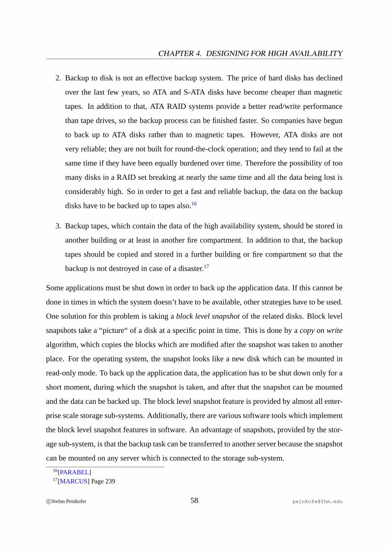
CHAPTER 4. DESIGNING FOR HIGH AVAILABILITY
2. Backup to disk is not an effective backup system. The price of hard disks has declined
over the last few years, so ATA and S-ATA disks have become cheaper than magnetic
tapes. In addition to that, ATA RAID systems provide a better read/write performance
than tape drives, so the backup process can be finished faster. So companies have begun
to back up to ATA disks rather than to magnetic tapes. However, ATA disks are not
very reliable; they are not built for round-the-clock operation; and they tend to fail at the
same time if they have been equally burdened over time. Therefore the possibility of too
many disks in a RAID set breaking at nearly the same time and all the data being lost is
considerably high. So in order to get a fast and reliable backup, the data on the backup
disks have to be backed up to tapes also.16
3. Backup tapes, which contain the data of the high availability system, should be stored in
another building or at least in another fire compartment. In addition to that, the backup
tapes should be copied and stored in a further building or fire compartment so that the
backup is not destroyed in case of a disaster.17
Some applications must be shut down in order to back up the application data. If this cannot be
done in times in which the system doesn’t have to be available, other strategies have to be used.
One solution for this problem is taking ablock level snapshotof the related disks. Block level
snapshots take a “picture“ of a disk at a specific point in time. This is done by acopy on write
algorithm, which copies the blocks which are modified after the snapshot was taken to another
place. For the operating system, the snapshot looks like a new disk which can be mounted in
read-only mode. To back up the application data, the application has to be shut down only for a
short moment, during which the snapshot is taken, and after that the snapshot can be mounted
and the data can be backed up. The block level snapshot feature is provided by almost all enter-
prise scale storage sub-systems. Additionally, there are various software tools which implement
the block level snapshot features in software. An advantage of snapshots, provided by the stor-
age sub-system, is that the backup task can be transferred to another server because the snapshot
can be mounted on any server which is connected to the storage sub-system.
16[PARABEL]17[MARCUS] Page 239
c©Stefan Peinkofer 58 [email protected]

4.1. SYSTEM MANAGEMENT AND ORGANIZATIONAL ISSUES
The major rule of backup is: The faster lost files can be restored from the backup, the better.
Unfortunately, this rule is often violated in favour of a fast backup process. Today’s magnetic
tape drives provide a write performance which is greater than the average read performance of
a file system on a single disk. To gain the full tape write performance, many backup systems
provide the ability to write more than one backup stream to a single tape simultaneously. This
speeds up the backup process but slows down the restoration process. For example if ten backup
streams are written to a tape simultaneously and the tape has a read/write performance of 30
MB/s, this means that the restore will run only with 3 MB/s18. Such features have to be used
with precaution. To speed up the overall time to restore, meaning the time which is needed from
starting the restore application until the system is available again, restoring a system should be
trained on a regular basis or at least a documented step-by-step restore procedure should be
created.
Normal backup software will require a working operating system and backup client applica-
tion in order to be able to restore the files from the backup system. So it’s a good idea to take
disk imagesof the local boot disks from time to time. These images usually back up the disk
on the block level and therefore preserve thepartition layoutand themaster boot recordof the
disk. So in case of a boot disk failure, the administrators just have to copy the disk image to the
new disk instead of reinstalling the complete operating system first, before the last backed up
state of the boot disk can be restored.
4.1.7 Disaster Recovery
Disaster recoverydeals with making the computer systems of a company (or even the whole
company) available again within a specific time span, in case of a disaster strike.19 A disaster is
an event which causes the unavailability of one or more computer systems or even the unavail-
18During my practice term, we had to spend the night and half of the next day at the customer’s site to restore 4
GB of data, because they backed up 40 parallel streams to one tape at the same time.19[ANON6]
c©Stefan Peinkofer 59 [email protected]
CHAPTER 4. DESIGNING FOR HIGH AVAILABILITY
ability of company parts or the whole company. Disasters can be major fire, flood, earthquake,
storm, war, plane crash, terrorist attack, sabotage, area wide power failure and many more.20
Clusters can protect against some, but not all, disasters because the maximum physical distance
between the cluster nodes is limited. The greater the distance between the nodes, the higher the
possibility of a split brain situation is.21 Placing the clusters in different buildings which are
some kilometres apart can protect against fire, plane crashes and floods but for other disasters,
the distance is not large enough.
There are many ways in which a company could protect against disasters and the concrete
implementation of disaster recovery goes beyond the scope of this thesis. We will just discuss
some high-level matters. The first thing which is needed is a backup computer center which is
far enough away from the primary center that the disaster cannot affect both sites.22 The second
thing that is needed for disaster recovery is a disaster recovery plan, which should contain at
least the following points:
• What types of disasters the plan covers.
• A risk analysis of each covered disaster type.
• What preventive actions were taken to prevent or contain the effects of the covered disas-
ter types.
• Who has to be notified about the disaster and who has arbitrament about all further actions
taken.
• Which systems are covered by the disaster recovery plan.
• How the data gets to the backup data center.
• Who is responsible for recovering the various systems.
20[MARCUS] Pages 302 - 30321[STOCK] Page 2222[MARCUS] Page 299
c©Stefan Peinkofer 60 [email protected]

4.1. SYSTEM MANAGEMENT AND ORGANIZATIONAL ISSUES
• With which priority the systems at the backup site should be started again.
• What steps have to be taken to start up the various systems.
• Who is responsible for maintaining the disaster recovery plan.23
It is mandatory that the disaster recovery plan is always up-to-date24 and that the procedures
in the plan are trained on a regular basis. It’s worth mentioning that even if a company cannot
afford a backup computer center for disaster recovery, it is a good idea to create at least a
computer center cold start plan. Because in case of a computer center shutdown as the effect of
a power outage, for instance, it usually takes weeks until everything works like it did before.25
4.1.8 Active/Passive vs. Active/Active Configuration
One of the main decisions which has to be made when deploying a high availability cluster is
whether at least one node should do nothing but wait until one of the others fails or whether
every node in the cluster should do some work. Anactive/passiveconfiguration has a slight
availability advantage againstactive/activeconfigurations because applications can cause sys-
tem outage, too. So the risk of a node not being available because of a software bug is higher
in an active/active configuration. However, to argue to the management that an active/passive
solution is needed can be hard because it’s not very economical. The economical balance can be
improved if the cluster contains more than two nodes so only one passive system is needed for
many active systems. But most high availability clusters used today are active/active solutions
because they appear to be more cost-efficient to the management. What has to be kept in mind
with active/active solutions is that every server must also have enough CPU power and memory
capacity to run all the cluster resources by itself. As the figures4.2 and4.1 show, active/pas-
sive solution require more servers than active/active solutions and active/active solutions require
more powerful servers than active/passive solutions.
23[ANON5]24[STOCK] Page 2025[SNOOPY] Page 8
c©Stefan Peinkofer 61 [email protected]
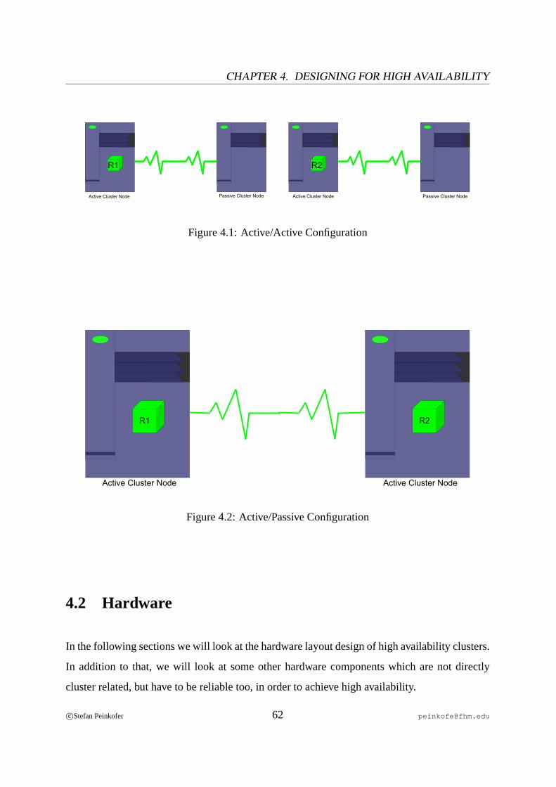
CHAPTER 4. DESIGNING FOR HIGH AVAILABILITY
R1R1 R1R2
Active Cluster Node Active Cluster NodePassive Cluster Node Passive Cluster Node
Figure 4.1: Active/Active Configuration
R1 R2
Active Cluster NodeActive Cluster Node
Figure 4.2: Active/Passive Configuration
4.2 Hardware
In the following sections we will look at the hardware layout design of high availability clusters.
In addition to that, we will look at some other hardware components which are not directly
cluster related, but have to be reliable too, in order to achieve high availability.
c©Stefan Peinkofer 62 [email protected]

4.2. HARDWARE
4.2.1 Network
Networks are not part of clusters, but since clusters usually provide their services over a net-
work, the network has to be highly available, too. There are many different implementations
which make networks highly available so we will discuss the whole issue just on a high level.
The first thing we have to consider is network connectivity. This can be divided into three
different paths:
1. Server to Switch
2. Switch to Switch
3. Switch to Router
In order to makeserver to switchconnections highly available, we need two network cards on
the server, which are connected to two different switches. In addition we need some piece of
software on the server which either detects the failure of a connection and fails communication
over to the other connection or which uses both connections at the same time and discontinues
the use of a failed connection automatically. Of course, the clients have to be connected to both
switches, too, in order to benefit from the highly available network.
Usually, a company network consist of more than two switches. In this case we have to consider
switch to switchconnections too. OnISO/OSI Layer 2, Ethernet based networks are not allowed
to contain loops. A loop is for example in a three switch network when switchA is connected
to B which is connected toC, which is connected toA. But without such a loop, one or more
switches can be a single point of failure, as shown in figure4.3.
c©Stefan Peinkofer 63 [email protected]
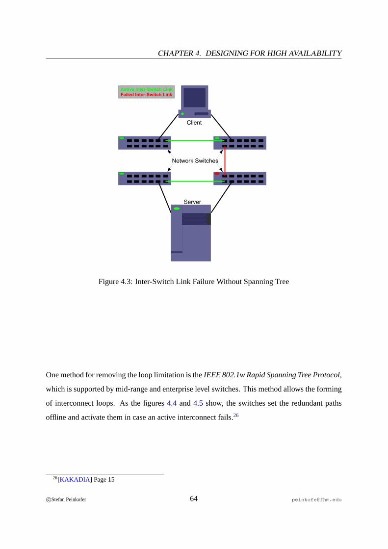
CHAPTER 4. DESIGNING FOR HIGH AVAILABILITY
Active Inter-Switch LinkFailed Inter-Switch Link
Client
Server
Network Switches
Figure 4.3: Inter-Switch Link Failure Without Spanning Tree
One method for removing the loop limitation is theIEEE 802.1w Rapid Spanning Tree Protocol,
which is supported by mid-range and enterprise level switches. This method allows the forming
of interconnect loops. As the figures4.4 and4.5 show, the switches set the redundant paths
offline and activate them in case an active interconnect fails.26
26[KAKADIA ] Page 15
c©Stefan Peinkofer 64 [email protected]
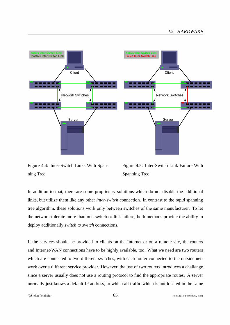
4.2. HARDWARE
Active Inter-Switch LinkInactive Inter-Switch Link
Client
Server
Network Switches
Figure 4.4: Inter-Switch Links With Span-
ning Tree
Active Inter-Switch LinkFailed Inter-Switch Link
Network Switches
Client
Server
Figure 4.5: Inter-Switch Link Failure With
Spanning Tree
In addition to that, there are some proprietary solutions which do not disable the additional
links, but utilize them like any otherinter-switchconnection. In contrast to the rapid spanning
tree algorithm, these solutions work only between switches of the same manufacturer. To let
the network tolerate more than one switch or link failure, both methods provide the ability to
deploy additionallyswitch to switchconnections.
If the services should be provided to clients on the Internet or on a remote site, the routers
and Internet/WAN connections have to be highly available, too. What we need are two routers
which are connected to two different switches, with each router connected to the outside net-
work over a different service provider. However, the use of two routers introduces a challenge
since a server usually does not use a routing protocol to find the appropriate routes. A server
normally just knows a default IP address, to which all traffic which is not located in the same
c©Stefan Peinkofer 65 [email protected]
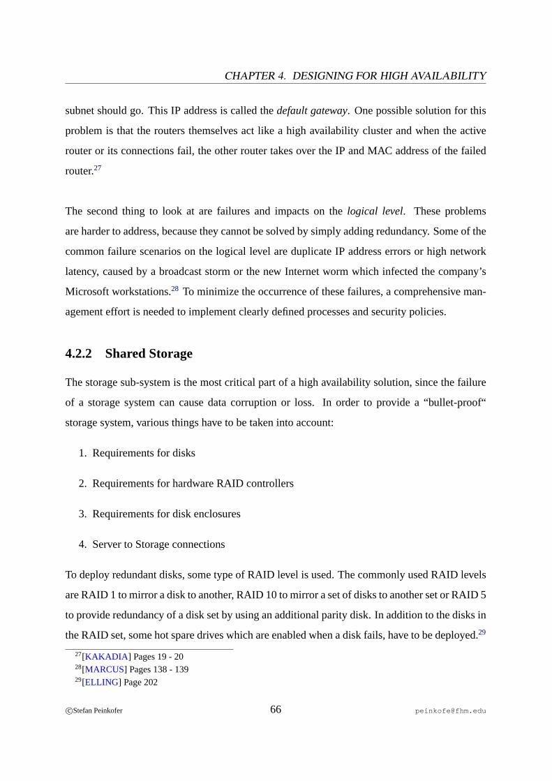
CHAPTER 4. DESIGNING FOR HIGH AVAILABILITY
subnet should go. This IP address is called thedefault gateway. One possible solution for this
problem is that the routers themselves act like a high availability cluster and when the active
router or its connections fail, the other router takes over the IP and MAC address of the failed
router.27
The second thing to look at are failures and impacts on thelogical level. These problems
are harder to address, because they cannot be solved by simply adding redundancy. Some of the
common failure scenarios on the logical level are duplicate IP address errors or high network
latency, caused by a broadcast storm or the new Internet worm which infected the company’s
Microsoft workstations.28 To minimize the occurrence of these failures, a comprehensive man-
agement effort is needed to implement clearly defined processes and security policies.
4.2.2 Shared Storage
The storage sub-system is the most critical part of a high availability solution, since the failure
of a storage system can cause data corruption or loss. In order to provide a “bullet-proof“
storage system, various things have to be taken into account:
1. Requirements for disks
2. Requirements for hardware RAID controllers
3. Requirements for disk enclosures
4. Server to Storage connections
To deploy redundant disks, some type of RAID level is used. The commonly used RAID levels
are RAID 1 to mirror a disk to another, RAID 10 to mirror a set of disks to another set or RAID 5
to provide redundancy of a disk set by using an additional parity disk. In addition to the disks in
the RAID set, some hot spare drives which are enabled when a disk fails, have to be deployed.29
27[KAKADIA ] Pages 19 - 2028[MARCUS] Pages 138 - 13929[ELLING] Page 202
c©Stefan Peinkofer 66 [email protected]

4.2. HARDWARE
The RAID functionality can either be done by software on the cluster nodes or, if available, by
a hardware RAID controller in the disk enclosure. Ifsoftware RAIDis used, some amount of
CPU and I/O capacity will be occupied by the RAID software. Since RAID 5 requires the cal-
culation of parity bits, deploying it with a software RAID solution is not recommended because
it doesn’t perform very well. In addition to that, not all software RAID solutions can be used
for shared cluster or SAN file systems.
The hardware RAIDcontroller must provide redundant I/O interfaces, so in case of an I/O
interconnect failure the nodes can use a second path to the controller. If a hardware RAID con-
troller uses a write cache it must be ensured that the controller’s write cache is battery backed
up or, if this is not the case, that the write cache is turned off. Otherwise, the data in the write
cache, which can be a few GB, is lost in case of a power outage.30 In addition to that, as shown
in figure 4.6, the RAID controllers themselves have to be redundant, so in case of a primary
controller failure, the secondary controller continues the work.
RAID Controller A RAID Controller B
SAN
Active ControllerStandby ControllerActive Connection to DisksStandby Connection to DisksActive Fibre Channel ConnectionStandby Fibre Channel Connection
Disk Enclosure
Health Monitoring
RedundantI/O Paths
Figure 4.6: Redundant RAID Controller Configuration
30[ELLING] Page 202
c©Stefan Peinkofer 67 [email protected]
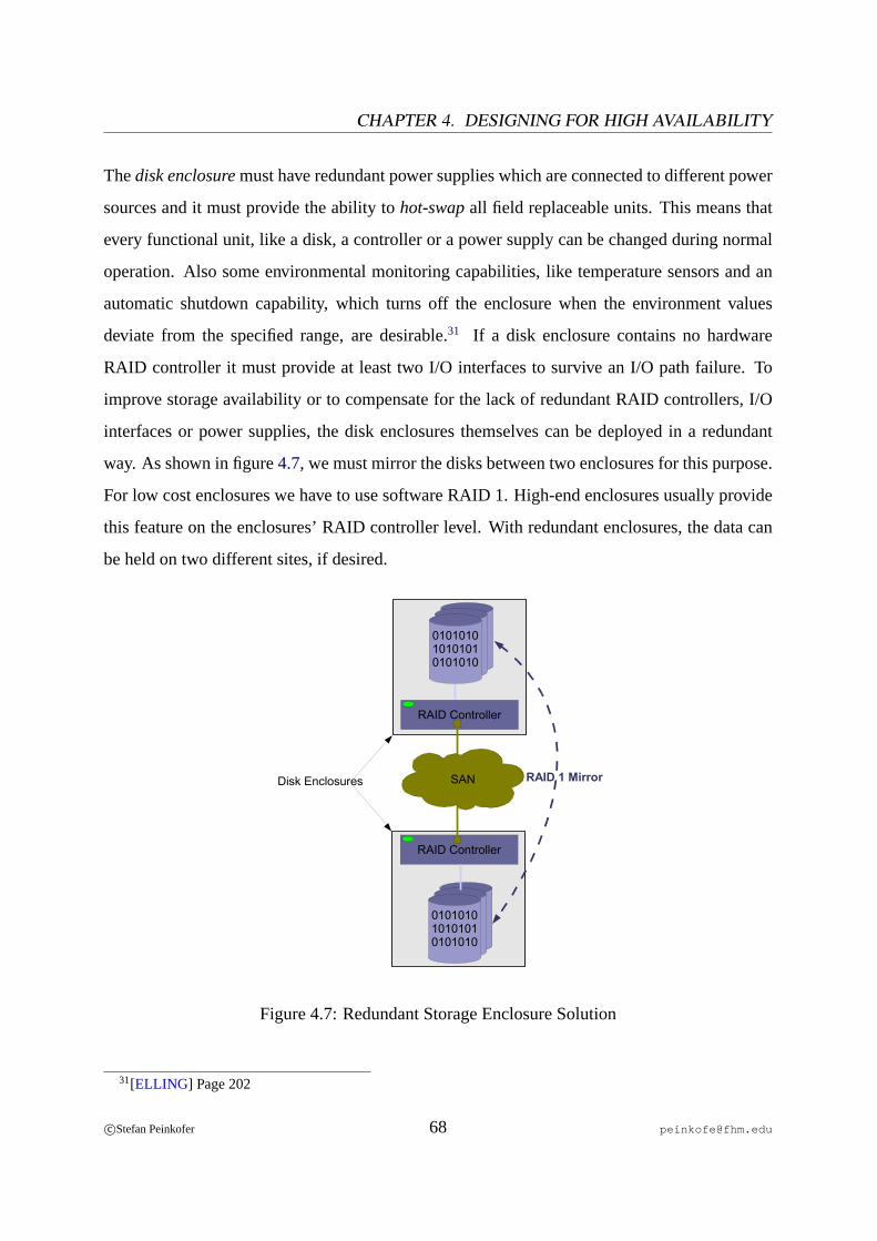
CHAPTER 4. DESIGNING FOR HIGH AVAILABILITY
Thedisk enclosuremust have redundant power supplies which are connected to different power
sources and it must provide the ability tohot-swapall field replaceable units. This means that
every functional unit, like a disk, a controller or a power supply can be changed during normal
operation. Also some environmental monitoring capabilities, like temperature sensors and an
automatic shutdown capability, which turns off the enclosure when the environment values
deviate from the specified range, are desirable.31 If a disk enclosure contains no hardware
RAID controller it must provide at least two I/O interfaces to survive an I/O path failure. To
improve storage availability or to compensate for the lack of redundant RAID controllers, I/O
interfaces or power supplies, the disk enclosures themselves can be deployed in a redundant
way. As shown in figure4.7, we must mirror the disks between two enclosures for this purpose.
For low cost enclosures we have to use software RAID 1. High-end enclosures usually provide
this feature on the enclosures’ RAID controller level. With redundant enclosures, the data can
be held on two different sites, if desired.
010101010101010101010
RAID Controller
010101010101010101010
RAID Controller
SAN RAID 1 MirrorDisk Enclosures
Figure 4.7: Redundant Storage Enclosure Solution
31[ELLING] Page 202
c©Stefan Peinkofer 68 [email protected]
4.2. HARDWARE
The same considerations as for networkserver to switchconnections apply also to fibre channel
server to switchconnections, if a SAN is used. In contrast to the networkswitch to switchcon-
nections, the loop restriction does not apply to SAN switches; hence, a SAN natively supports
fault resilient topologies. In contrast to Ethernet networks, the costs per connection port of
SANs are not yet negligible. To let the SAN tolerate more than one failure at a time, additional
inter-switchlinks are needed, so the decision regarding how many failures the SAN can tolerate
should be based upon a comprehensive cost/risk analysis.
If a cluster system is connected to a SAN and uses SCSI reservations for fencing, it must be en-
sured that it will only reserve the shared disks which are dedicated to the cluster system. Usually
the cluster system will provide a method to exclude shared disks from the fencing operation. If
this method is based on an “opt-out“ algorithm, the system administrators must continuously
maintain the list of excluded shared disks so that in case of newly added shared disks the clus-
ter does not place SCSI reservations on them. A better approach is the use ofLUN (Logical
Unit Number) masking, which provides the ability to define which hosts can access a shared
disk, directly on the corresponding storage device. However, this function is not provided by
all storage devices.
4.2.3 Server
Today’s server market provides an uncountable number of different server types, with different
availability features. Generally, high-end servers can be unrestrictedly used as cluster nodes
since they were designed with availability considerations in mind. However, things look differ-
ent at the low-end side. In low-end servers, sometimes even basic availability features are not
implemented in order to achieve a lower price. Since many smaller companies on the one hand
cannot afford and don’t even need enterprise scale servers, but on the other hand have a demand
for high availability clusters, we will look only at the basic availability features of servers in a
cluster environment.
The first component we have to look at are the power supplies. They must be redundant and
c©Stefan Peinkofer 69 [email protected]
CHAPTER 4. DESIGNING FOR HIGH AVAILABILITY
additionally provide the capability to be connected to two different power sources. The cooling
fans of the server chassis must provide at least anN + 1 redundancy, which means that the fail-
ure of one fan can be compensated by the other fans. Like the storage enclosure, environmental
monitoring and automatic shutdown functions are desirable to prevent hardware damage.32 The
server should have at least two internal disks, so that the operating system and local data can
be mirrored to the second disk. In addition, the disks should be connected to two different I/O
controllers, so in case of a controller failure only one disk is unavailable. Also it must be en-
sured that the server can also boot from the second disk, in case the primary disk fails. At least
the power supplies and the disks must be hot pluggable. The server must provide enough PCI
slots to contain the needed PCI cards like network or I/O controllers. At a minimum, it must
provide two network connections to the public net, two connections for the cluster interconnect,
and two I/O controller cards. Also it should use two separate PCI buses so the failure of a bus
affects only half of the PCI cards. Some vendors provide PCI cards which provide more than
one connection at once, such as dual or quad Ethernet cards. If such cards are used, at least two
of them must be used so the cards don’t become single points of failure. The system memory
must be ECC memory to prevent memory corruption.
In addition to the availability features, servers as well as storages should be acquired with later
increases of capacity requirements in mind. It’s always a good idea to have some free slots for
CPUs, memory and disk expansions, since otherwise we will be forced to acquire new servers
and to build a new cluster, when the actual capacity requirements exceed the system capacity.33
4.2.4 Cables
Cables are a common source of failures in computer environments. Often, they get accidentally
disconnected because someone thinks they are no longer being used or they get cut during
construction or maintenance work. To minimize the potential danger of cables, we have to
consider them in the design process. The first rule is that all cables should be labeled at both
32[ELLING] Page 20133[MARCUS] Page 40
c©Stefan Peinkofer 70 [email protected]
4.2. HARDWARE
ends. The label should tell where the cable comes from and where it should go. If the cabling is
changed for some reason, the labels have to be immediately updated, too, since a false label is
worse than no label. The second rule is that redundant cables should be laid in different lanes.
For example, if we have our cluster nodes in two different buildings and all cables between the
nodes are laid in the same lane, an excavator who digs at the wrong place will likely cut all
the cables. This rule also applies to externally maintained cables, like redundant Internet/WAN
connections and power grid connections. It is worth mentioning that we must not assume that
two different suppliers use two different cable lanes. So it has to be ensured with the suppliers
that different lanes are used.34
4.2.5 Environment
As last but not least item we have to consider in the hardware design process is the environment
in which the cluster system will be deployed. A high availability system can only be benefi-
cial if the environment meets some criteria. The first point we have to consider are the power
sources. A power outage is probably the most dangerous threat for data centers since even if the
center is well prepared, something will always go wrong in case of emergency. To minimize the
effects of a power outage, at least battery backed upuninterruptible power supplieshave to be
used, to bridge over short power outages and let the systems gracefully shut down in case of a
longer power outage. If the systems are critical enough that they have to be available even in the
case of a longer power outage, the use of backuppower generatorsis mandatory. What has to
be kept in mind is that these generators require fuel in order to operate, so the fuel tank should
be always filled completely. Also it’s a good idea to use redundant power grid connections, but
it has to be ensured that the power comes from different power lines.35
The second item to consider is the air conditioning. As we have already discussed in previous
chapters, the systems should be able to shut down themselves if the environmental temperature
gets too high. In order to prevent this situation, the air conditioning has to be redundant. High
34[SNOOPY] Page 835[SNOOPY] Pages 7 - 8
c©Stefan Peinkofer 71 [email protected]
CHAPTER 4. DESIGNING FOR HIGH AVAILABILITY
temperature can not only be caused by an air conditioning failure, it can also occur if the cooling
power of the air conditioning becomes insufficient. This can for example occur because of high
outdoor temperature or because some new servers were added to the computer room. Therefore
the environmental temperature and the relative humidity has to be monitored continuously and
someone has to be notified if it increases beyond some value.36 If the redundant air condition-
ing runs in an active/active configuration, it must be ensured that one air conditioner alone can
deliver sufficient cooling power for the computer center. Therefore the waste heat produced by
the IT systems has to be compared with the cooling power of the air conditioning, every time a
new system is added to the center.
The third problem we have to deal with is dust. Dust can cause overheating if it deposits
on cooling elements or if it clogs air filters. Also, it can damage the bearings of cooling fans.
In addition to that, metallic particles can cause short circuits in the electric components. To
minimize contamination, the air in the computer room should be filtered and the filters should
be maintained regularly.37
The fourth issue is theautomatic fire extinguishing equipment, deployed in the computer room.
Under all circumstances, the equipment must use a extinguishing device which causes no dam-
age to the electrical equipment. So water or dry powder must not be used.38 If such a system
cannot be afforded, it’s better to have no automatic fire extinguishing equipment at all, since
it usually causes more damage than the fire itself. However, in this case it is mandatory that
the fire alarms automatically notify the fire department and that fast and highly available first
responders are available, like janitors who live in the building which contains the computer sys-
tems.
In addition to the four main concerns we discussed above some other precautions have to be
taken, depending on the geographical position of the data center. For example in earthquake
36[ELLING] Page 20137[ELLING] Page 20138[ELLING] Page 201
c©Stefan Peinkofer 72 [email protected]
4.3. SOFTWARE
prone areas, the computer equipment has to be secured to the floor to prevent it from falling
over. Also, it’s a good idea to keep all computer equipment on at least the first floor, not only in
flood prone areas.
4.3 Software
The last big area of design are the software components which will be used on the cluster sys-
tem. This area is divided into four main components: the operating system, the cluster software,
the applications which should be made highly available and the cluster agents for the applica-
tions. In addition to the component specific design considerations, there are some common
issues which should be mentioned. The first rule in the software election process for a high
availability system is to use only mature and well tested software. This will minimize the like-
lihood of experiencing new software bugs, because many of them will have already been found
by other people. However, if the deployment of a “x.0 software release“ is necessary, plenty of
time should be scheduled for testing the software in a non-productive environment. All prob-
lems and bugs which are found during testing must be reported to the software producers.39 The
software producers will need some time until they deliver a patch for the bugs. This should also
be considered in the project time plan.
For each commercial software product which is deployed in the cluster, a support contract
should be concluded to get support if something doesn’t work as expected. Unlike to the open
source community, commercial software producers will not provide support at no charge. In
addition to that, not all known bugs and problems are disclosed to the public. So in order to
get the information needed, a support case has to be submitted. Without a support contract,
these calls will be deducted on a time and material basis, which is in the long term usually more
expensive than a support contract. Typically different support contracts with different service
level agreements are available. For high availability systems, premium grade support contracts
which provide the ability to get support round the clock should be chosen.
39[PFISTER] Page 395
c©Stefan Peinkofer 73 [email protected]
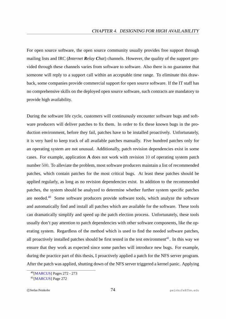
CHAPTER 4. DESIGNING FOR HIGH AVAILABILITY
For open source software, the open source community usually provides free support through
mailing lists and IRC (InternetRelayChat) channels. However, the quality of the support pro-
vided through these channels varies from software to software. Also there is no guarantee that
someone will reply to a support call within an acceptable time range. To eliminate this draw-
back, some companies provide commercial support for open source software. If the IT staff has
no comprehensive skills on the deployed open source software, such contracts are mandatory to
provide high availability.
During the software life cycle, customers will continuously encounter software bugs and soft-
ware producers will deliver patches to fix them. In order to fix these known bugs in the pro-
duction environment, before they fail, patches have to be installed proactively. Unfortunately,
it is very hard to keep track of all available patches manually. Five hundred patches only for
an operating system are not unusual. Additionally, patch revision dependencies exist in some
cases. For example, applicationA does not work with revision10 of operating system patch
number500. To alleviate the problem, most software producers maintain a list of recommended
patches, which contain patches for the most critical bugs. At least these patches should be
applied regularly, as long as no revision dependencies exist. In addition to the recommended
patches, the system should be analyzed to determine whether further system specific patches
are needed.40 Some software producers provide software tools, which analyze the software
and automatically find and install all patches which are available for the software. These tools
can dramatically simplify and speed up the patch election process. Unfortunately, these tools
usually don’t pay attention to patch dependencies with other software components, like the op-
erating system. Regardless of the method which is used to find the needed software patches,
all proactively installed patches should be first tested in the test environment41. In this way we
ensure that they work as expected since some patches will introduce new bugs. For example,
during the practice part of this thesis, I proactively applied a patch for the NFS server program.
After the patch was applied, shutting down of the NFS server triggered a kernel panic. Applying
40[MARCUS] Pages 272 - 27341[MARCUS] Page 272
c©Stefan Peinkofer 74 [email protected]

4.3. SOFTWARE
such a patch to a production environment can cause unexpected downtime and it will definitely
require planned downtime, to isolate and back out the faulty patch.
If software is deployed on a cluster system, special requirements or restrictions can exist. It
is mandatory to read the documentation of the deployed software and follow the stated guide-
lines. This is of particular importance if support contracts are concluded, since the software
producers will usually refuse to support a configuration which violates their restrictions42.
4.3.1 Operating System
The first design issue on the operating system level is the partition layout of the boot disk. The
first task for this is to find out whether the cluster software, the volume manager or an appli-
cation has special requirements for the partition layout. If these requirements are not known
before creating the partition layout, a repartitioning of the boot disk and therefore a reinstall of
the operating system may be needed. After these requirements are met, the partition layout for
the root file systemcan be designed. As a general rule, it should be as simple as possible. So
creating one partition for the whole root file system is advisable, but only if the available space
on the root file system is sufficiently big. Cluster systems typically produce a huge amount of
log file messages. These messages are usually automatically deleted after some time. However,
if the root file system is too small, it may run out of space when too many log file messages
are generated over time. In such a situation, along with all other negative effects of a full file
system, no one will be able to log on to the node, since the log on procedure will try to write
some information to disk, which of course fails. For smaller root file system partitions it is rec-
ommended to put the/var directory, which contains the system log messages, on a separate
partition so that the administrator can still log on in such a situation.
Depending on the deployed cluster software, somelocal component fail overmechanisms are
relinquished to the operating system. For example, fail over of redundant storage paths is often
42This goes so far that you will not be supported even if your problem obviously has nothing to do with the
violation.
c©Stefan Peinkofer 75 [email protected]
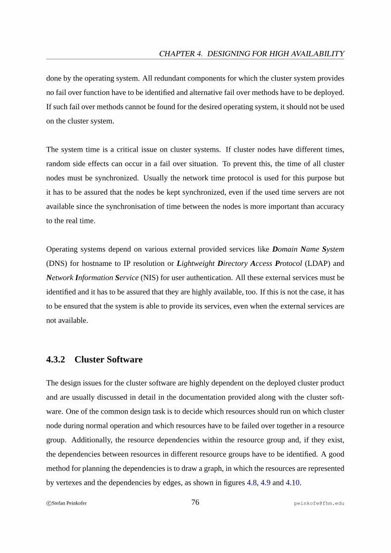
CHAPTER 4. DESIGNING FOR HIGH AVAILABILITY
done by the operating system. All redundant components for which the cluster system provides
no fail over function have to be identified and alternative fail over methods have to be deployed.
If such fail over methods cannot be found for the desired operating system, it should not be used
on the cluster system.
The system time is a critical issue on cluster systems. If cluster nodes have different times,
random side effects can occur in a fail over situation. To prevent this, the time of all cluster
nodes must be synchronized. Usually the network time protocol is used for this purpose but
it has to be assured that the nodes be kept synchronized, even if the used time servers are not
available since the synchronisation of time between the nodes is more important than accuracy
to the real time.
Operating systems depend on various external provided services likeDomain NameSystem
(DNS) for hostname to IP resolution orLightweightDirectory AccessProtocol (LDAP) and
NetworkInformationService(NIS) for user authentication. All these external services must be
identified and it has to be assured that they are highly available, too. If this is not the case, it has
to be ensured that the system is able to provide its services, even when the external services are
not available.
4.3.2 Cluster Software
The design issues for the cluster software are highly dependent on the deployed cluster product
and are usually discussed in detail in the documentation provided along with the cluster soft-
ware. One of the common design task is to decide which resources should run on which cluster
node during normal operation and which resources have to be failed over together in a resource
group. Additionally, the resource dependencies within the resource group and, if they exist,
the dependencies between resources in different resource groups have to be identified. A good
method for planning the dependencies is to draw a graph, in which the resources are represented
by vertexes and the dependencies by edges, as shown in figures4.8, 4.9and4.10.
c©Stefan Peinkofer 76 [email protected]
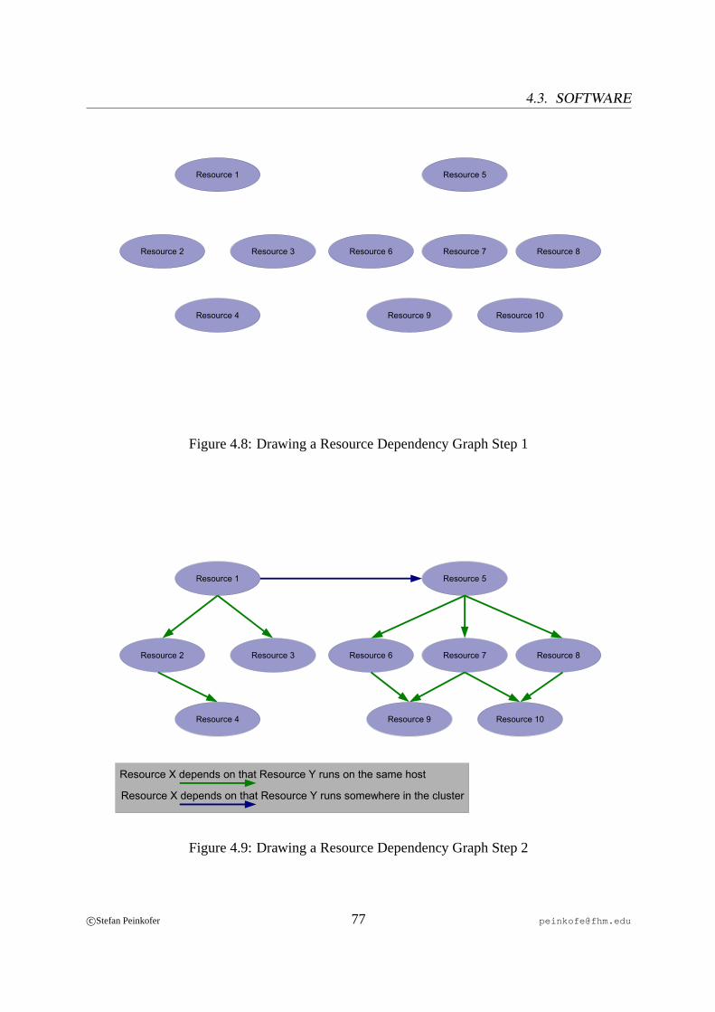
4.3. SOFTWARE
Resource 1
Resource 2 Resource 3 Resource 7Resource 6 Resource 8
Resource 5
Resource 4 Resource 9 Resource 10
Figure 4.8: Drawing a Resource Dependency Graph Step 1
Resource 1
Resource 2 Resource 3 Resource 7Resource 6 Resource 8
Resource 5
Resource 4 Resource 9 Resource 10
Resource X depends on that Resource Y runs on the same host
Resource X depends on that Resource Y runs somewhere in the cluster
Figure 4.9: Drawing a Resource Dependency Graph Step 2
c©Stefan Peinkofer 77 [email protected]
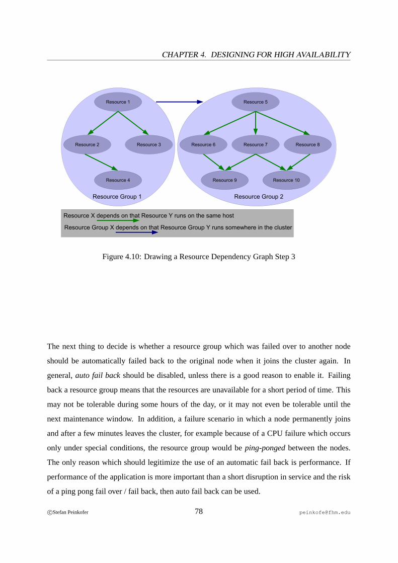
CHAPTER 4. DESIGNING FOR HIGH AVAILABILITY
Resource 1
Resource 2 Resource 3 Resource 7Resource 6 Resource 8
Resource 5
Resource 4 Resource 9 Resource 10
Resource Group 1 Resource Group 2
Resource X depends on that Resource Y runs on the same host
Resource Group X depends on that Resource Group Y runs somewhere in the cluster
Figure 4.10: Drawing a Resource Dependency Graph Step 3
The next thing to decide is whether a resource group which was failed over to another node
should be automatically failed back to the original node when it joins the cluster again. In
general,auto fail backshould be disabled, unless there is a good reason to enable it. Failing
back a resource group means that the resources are unavailable for a short period of time. This
may not be tolerable during some hours of the day, or it may not even be tolerable until the
next maintenance window. In addition, a failure scenario in which a node permanently joins
and after a few minutes leaves the cluster, for example because of a CPU failure which occurs
only under special conditions, the resource group would beping-pongedbetween the nodes.
The only reason which should legitimize the use of an automatic fail back is performance. If
performance of the application is more important than a short disruption in service and the risk
of a ping pong fail over / fail back, then auto fail back can be used.
c©Stefan Peinkofer 78 [email protected]
4.3. SOFTWARE
4.3.3 Applications
On the application level, again many design issues are unique for the particular application. The
first common design task is to decide which software product should be used in order to pro-
vide the desired service. An application which should be deployed on a high availability cluster
system has to meet some requirements. The application must provide its services through a
client/servermodel, whereby the clients access the server over a path which can be failed over
from one node to another. For example an application which is connected to its clients over a
serial line cannot be deployed on a high availability cluster. In addition, most cluster systems
will only support the use of TCP/IP asclient access path.
Some applications require human intervention to recover when they are restarted after a sys-
tem crash or they require the administrator to provide a password during the start-up process,
for example. Such applications are also not suitable for high availability clusters. In addition
to that, the recovery process must finish within a predictable time limit. The time limit can be
specified by the administrator and it is used by the cluster software to determine whether an
application failed during the start procedure.
Since the application data and eventually the application configuration files must be placed
on a shared storage, the location of these files must be configurable. If this is not the case it can
be next to impossible to place the files on a shared storage.
If the application provides its service through TCP/IP43 the cluster has to be configured to pro-
vide one or more dedicated IP addresses, which will be failed over along with the application.
For this reason, the application must provide the ability to let the system administrator define to
which IP addresses the application should bind. Some applications which do not provide this
feature will bind to all available IP addresses on the system. That behavior is acceptable, as
long as no other application running on the cluster uses the same TCP port. If both applications
43What is the default for applications deployed on a HA cluster.
c©Stefan Peinkofer 79 [email protected]
CHAPTER 4. DESIGNING FOR HIGH AVAILABILITY
ran on the same host, one application would not be able to bind to the IP addresses.44
The decision which has to be made after the software product election is how the applica-
tion will be installed. Option one is to place the application binaries and configuration files
on the shared storage and option two is to place them on the local disk of each cluster node.
Each option has assets and drawbacks. Option one provides the advantage that only one copy of
the application and configuration files has to be maintained. Applying patches or changing the
configuration has to be done only once. The disadvantage is that the application has to be shut
down cluster wide in order to upgrade the application. Option two provides the advantage of
rolling upgrades. The software can first be upgraded or reconfigured on the standby nodes and,
after that, the service can be switched over to an upgraded node in order to perform the upgrade
on the other node. This provides the additional advantage that when a problem arises during the
upgrade process or during the start of the new version or new configuration of the software, the
node which hosted the application originally provides a fail back opportunity45. The disadvan-
tage is that several copies of the application and the configuration have to be maintained. Also
it must be ensured that the configuration files are synchronized on all hosts.46
Sometimes, applications depend on services which are not provided by applications that run
on the cluster system. These services have to be identified and it must be ensured that they are
highly available. A better approach would be to deploy the applications which provide these
services on the same cluster as the applications that depend on the services. This allows the
cluster system to take care of the dependencies.
4.3.4 Cluster Agents
The design of a cluster agent depends mainly on two factors. The used cluster software, which
specifies the functions that must or can be provided by the agent and the application the clus-
44[BIANCO] Pages 45 - 4945Note that this doesn’t remove the need to test the upgrade on the test environment in the first place.46[ANON7] Pages 16 - 17
c©Stefan Peinkofer 80 [email protected]
4.3. SOFTWARE
ter agent should handle, specifies how the application can be started, stopped and monitored.
Usually, an application can be monitored in different ways and in different detail. The more
detailed the monitoring of the application is, the more failures can be detected and the better
fault reporting can be provided. What should be kept in mind is that the complexity of the
agent will increase along with the monitoring detail and therefore the likelihood that the agent
itself contains bugs and hence may fail is increased also.47 So the general design rule for the
monitoring function is as detailed as needed and as simple as possible.
One requirement of nearly any cluster system is that all or at least some of the resource agent
functions have to beidempotent. Idempotency means that the result of calling a function two or
more times in a row is the same as calling the function only once. For example calling the stop
function once should stop the resource and return successful. Calling the stop function a second
time should leave the resource stopped and return successful. Or calling the start function once
should start the resource and return successful. Calling the start function a second time should
not start the resource again48, but only return successful.
47[ELLING] Page 9548We assume that the resource is still running.
c©Stefan Peinkofer 81 [email protected]
Chapter 5
IT Infrastructure of the
Munich University of Applied Sciences
In the following chapter we will look at the infrastructure which is used by the sample imple-
mentations of the Sun Cluster and Heartbeat high availability cluster systems and also analyze
which of these components constitute a single point of failure.
5.1 Electricity Supply
As figure5.1 shows, the building which contains the server room provides three main electric
circuits whereby two of them are available in the server room and each device with a redundant
power supply is connected to both circuits. Each of the main circuits is fed by a dedicated
transformer in the basement of the building. However, each of the transformers is fed by only
one common high voltage transmission line. Therefore the provision of electricity is a single
point of failure. Because of the high costs of a second high-voltage transmission line or a
centralized uninterruptible power supply system and the relatively rare occurrence of major
power outages, this single point of failure will probably never be removed.
82

5.2. AIR CONDITIONING
Server Room
High Voltage Transmission Line
Transformers
Main circuits
Figure 5.1: Electricity Supply of the Server Room
5.2 Air Conditioning
The air conditioning of the server room is provided by two air conditioning units which work in
an active/active configuration. Although in the past one unit alone was able to handle the waste
heat of the IT systems, this is not true anymore. More and more servers have been deployed
over the last years, and so the produced waste heat has exceeded the cooling capacity of a single
air conditioning unit. So the air conditioning is a single point of failure1. A direct solution for
removing the single point of failure, namely installing new air conditioning units with higher
capacity, is not possible for cost reasons. In the building which contains the computer room,
there are two other rooms with autonomous air conditioning. Since these rooms will be released
in the near future, because the faculty which owns the rooms is moving to another building, the
redundancy of the air conditioning in the central computer room could be restored, by moving
some servers to the other rooms.
1This has already failed more than once.
c©Stefan Peinkofer 83 [email protected]
CHAPTER 5. IT INFRASTRUCTURE OF THEMUNICH UNIVERSITY OF APPLIED SCIENCES
5.3 Public Network
The public network of the Munich University of Applied Sciences spreads out over several
buildings which are distributed across the whole city. Every building is connected to a router in
building G which also contains the central server room. Indeed, mostsub-networkswithin the
buildings are redundant by using the rapid spanning tree algorithm and a proprietary enhance-
ment. The connections to the router and the router itself are not redundant. In addition to that,
no redundant Internet connection is available. So the router itself, the inter-building and Inter-
net connections are single points of failures. Unfortunately, the situation cannot be improved in
the medium term because fully redundant inter-building connections would cost several million
euros.
Although the network within the building, which contains the server room, provides redun-
dancy, most servers and workstations do not fully utilize the feature yet. They are connected
to the network over just one path. If a switch fails, network connection to/from the comput-
ers, connected to the failed switch, is lost. What makes this fact worse is that most switches
do not have redundant power supplies because of cost reasons. So, from the point of view of
the cluster system, the switch to service consumer connection is a single point of failure. In
the short term, this single point of failure is planned to be removed for the servers, which use
the services provided by the high availability clusters and the servers which provide services
on which the clusters depend. However, even in the medium term, the single point of failure
cannot be removed for workstations because the costs would be too high.
As we have seen, the public network is an area which needs further improvement in order to
provide comprehensive reliability for all who use the services provided by the cluster systems.
c©Stefan Peinkofer 84 [email protected]

5.4. SHARED STORAGE DEVICE
5.4 Shared Storage Device
As shared storage device, theSun StorEdge 3510fibre channel array is used. The array uses
hot pluggable, redundant power supplies, cooling fans and RAID controllers which fail over
the data flow transparent to the connected servers, in case of a controller failure. Also every
controller provides two I/O paths, which can be connected to the SAN. In addition to that, the
controller can work in an active/active configuration in which every controller maintains one or
more separate RAID sets. This feature is especially useful if RAID 5 is used, since the load
for computing the parity bits is distributed among both controllers. Furthermore the enclosure
provides a comprehensive set of monitoring features and in conjunction with a special software,
the administrators can be automatically notified about critical events. The 3510 also supports
LUN maskingbut unfortunately nooff-site mirroring. So mirroring disks between different en-
closures has to be done by software RAID tools.
As figure 5.2 shows, in our configuration the 3510 contains two RAID 5 sets consisting of
5 disks each and additionally two hot spare disks are deployed. To increase the performance,
the RAID sets are maintained by the controllers in an active/active configuration.
As we have seen, the 3510 storage array meets all requirements to provide highly available
data access and therefore is suitable to be deployed in a high availability cluster environment.
c©Stefan Peinkofer 85 [email protected]
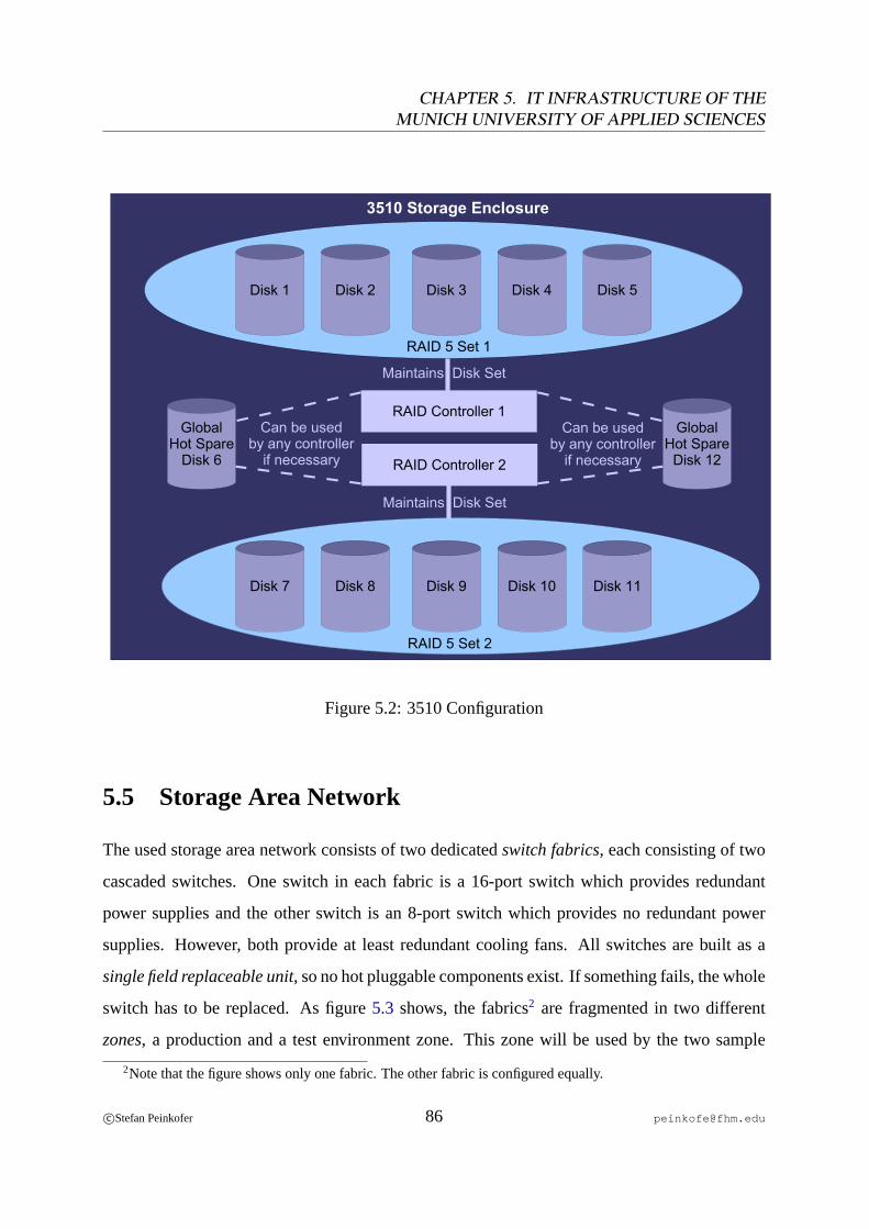
CHAPTER 5. IT INFRASTRUCTURE OF THEMUNICH UNIVERSITY OF APPLIED SCIENCES
RAID Controller 1
RAID Controller 2
Disk 1 Disk 2 Disk 3 Disk 4 Disk 5
Disk 7 Disk 8 Disk 9 Disk 10 Disk 11
GlobalHot Spare
Disk 6
GlobalHot Spare
Disk 12
RAID 5 Set 2
RAID 5 Set 1
Maintains Disk Set
Maintains Disk Set
Can be usedby any controller
if necessary
Can be usedby any controller
if necessary
3510 Storage Enclosure
Figure 5.2: 3510 Configuration
5.5 Storage Area Network
The used storage area network consists of two dedicatedswitch fabrics, each consisting of two
cascaded switches. One switch in each fabric is a 16-port switch which provides redundant
power supplies and the other switch is an 8-port switch which provides no redundant power
supplies. However, both provide at least redundant cooling fans. All switches are built as a
single field replaceable unit, so no hot pluggable components exist. If something fails, the whole
switch has to be replaced. As figure5.3 shows, the fabrics2 are fragmented in two different
zones, a production and a test environment zone. This zone will be used by the two sample
2Note that the figure shows only one fabric. The other fabric is configured equally.
c©Stefan Peinkofer 86 [email protected]
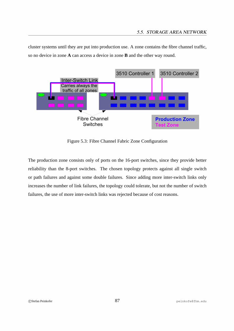
5.5. STORAGE AREA NETWORK
cluster systems until they are put into production use. A zone contains the fibre channel traffic,
so no device in zoneA can access a device in zoneB and the other way round.
Production ZoneTest Zone
3510 Controller 1 3510 Controller 2Inter-Switch LinkCarries always the traffic of all zones
Fibre ChannelSwitches
Figure 5.3: Fibre Channel Fabric Zone Configuration
The production zone consists only of ports on the 16-port switches, since they provide better
reliability than the 8-port switches. The chosen topology protects against all single switch
or path failures and against some double failures. Since adding more inter-switch links only
increases the number of link failures, the topology could tolerate, but not the number of switch
failures, the use of more inter-switch links was rejected because of cost reasons.
c©Stefan Peinkofer 87 [email protected]
Chapter 6
Implementing a High Availability Cluster
System Using Sun Cluster
6.1 Initial Situation
Currently only a single server hosts the file serving applications NFS and Samba for the users’
home directories. This server is based on the SPARC platform and runs the Solaris 9 operating
system. The home directory data is placed on a 1 TB shared disk, which is hosted on a 3510 fibre
channel storage array. The file system used on this volume is a non-shared SUN QFS, which
would also provide the possibility to be deployed as ashared SAN file system. In addition to
that, the server also hosts the Radius authentication service.
6.2 Requirements
The requirements for the new system are two-tiered. Tier one is to provide a high availability
cluster solution, using two SPARC based servers, Solaris 10 as operating system and Sun Clus-
ter as cluster software. On this cluster system, the services NFS, Samba and Radius should be
made highly available. To eliminate the need to migrate the home directory data to a new file
system, the cluster should be able to use the already existing SUN QFS file system, once the
cluster goes into production. In addition to that, the SUN QFS file system should be deployed
88
6.3. GENERAL INFORMATION ON SUN CLUSTER
asasymmetric shared SUN QFS1, and thereby act as acluster file system, in order to distribute
the load of NFS and Samba among the two nodes, by running NFS on one and Samba on the
other node.
Tier two of the requirements is to evaluate whether the SUN QFS which contains the home
directory data can also be deployed as ahighly available SAN file systemso that servers outside
of the cluster can access the home directory data directly over the SAN. This is mainly needed
for backup reasons because backing up a terabyte over the local area network would take too
much time. In order to do aLAN-less backup, the backup server must be able to mount the
home directory volume, which is of course not possible with a cluster file system.
6.3 General Information on Sun Cluster
The Sun Cluster software is actually a hybrid cluster, which can be deployed as traditionalFail
Overcluster as well asLoad Balancingor High Performancecluster. Thereby, Sun Cluster pro-
vides various mechanisms and APIs which can be used by the corresponding types of services.
For example, Sun Cluster provides an integrated load balancing mechanism whereby one node
receives the requests and distributes them among the available nodes. For High Performance
Computing, Sun Cluster provides aRemote Shared MemoryAPI, which enables an application,
running on one node, to access a memory region of another node. However, the features for
load balancing and high performance computing are not further discussed in this thesis.
Sun Cluster supports three different types of cluster interconnects.
• Ethernet
• ScalableCoherentInterconnect(SCI)
• Sun Fire Link
1QFS provides the possibility to migrate a non-shared QFS to a shared QFS and vice versa.
c©Stefan Peinkofer 89 [email protected]
CHAPTER 6. IMPLEMENTING A HIGH AVAILABILITY CLUSTER SYSTEM USINGSUN CLUSTER
For normal fail over and load balancing clusters, typically Ethernet is used as cluster inter-
connect, whereby Sun Cluster uses raw Ethernet packets to exchange heartbeats and TCP/IP
packets to exchange further data. SCI or Sun Fire Link are typically used in a high performance
computing configuration, since these interconnects enable the remote shared memory feature.
Also larger load balancing configurations may benefit from these cluster interconnects because
of their low latency and high data bandwidth.
Sun Cluster uses a shared disk asquorum tie breakerand SCSI-2 or respectively SCSI-3 reser-
vations to fence a failed node. In addition to the raw SCSI reservations, Sun Cluster deploys a
so-calledfailfastdriver on each cluster node, which initiates a kernel panic when a node gets an
SCSI reservation conflictwhile trying to access a disk.
6.4 Initial Cluster Design and Configuration
In the following sections we will discuss the design of the cluster for the tier one requirements.
6.4.1 Hardware Layout
To build the cluster, two machines of different types were available: OneSUN Fire V440and one
SUN Enterprise 450. Each server must provide various network and fibre channel interfaces:
Two for connecting to the public network, two for the cluster interconnect network and two fibre
channel interfaces for connecting to the storage area network. An additional connection for a
SUN QFS meta data networkis not needed, since a design restriction for deploying SUN QFS
as a cluster file system is that the cluster interconnect has to be used for meta data exchange. For
the public network connection, 1 GBit fibre optic Ethernet connections are deployed because the
public network switches mainly provide fibre optic ports. For the cluster interconnect, copper
based Ethernet is deployed because it is cheaper than fibre optics. Figures6.1 and6.2 show
how the interface cards are installed in the servers.
c©Stefan Peinkofer 90 [email protected]
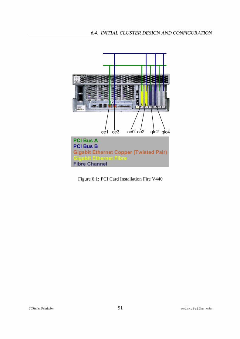
6.4. INITIAL CLUSTER DESIGN AND CONFIGURATION
qlc2 qlc4ce1 ce2ce0ce3
PCI Bus APCI Bus BGigabit Ethernet Copper (Twisted Pair)Gigabit Ethernet FibreFibre Channel
Figure 6.1: PCI Card Installation Fire V440
c©Stefan Peinkofer 91 [email protected]

CHAPTER 6. IMPLEMENTING A HIGH AVAILABILITY CLUSTER SYSTEM USINGSUN CLUSTER
ce1
ce2ce3
ce0
qlc0qlc1
glm2
PCI Bus APCI Bus BGigabit Ethernet Copper (Twisted Pair)Gigabit Ethernet FibreFibre ChannelSCSI Controller
Figure 6.2: PCI Card Installation Enterprise 450
The V440 already provides two copper gigabit Ethernet connection on board. Each of them is
addressed by a different PCI bus. The additional network and fibre channels cards are installed
in the PCI slots. One half is connected to PCI busA and the other half to PCI busB. This hard-
ware setup of the V440 can tolerate a PCI bus failure. Unfortunately, this could not be achieved
for the Enterprise 450, although it provides two dedicated PCI buses. The problem is that one
of the busses provides only two PCI slots which can handle 64-bit cards and all interface cards
require 64-bit slots.
c©Stefan Peinkofer 92 [email protected]
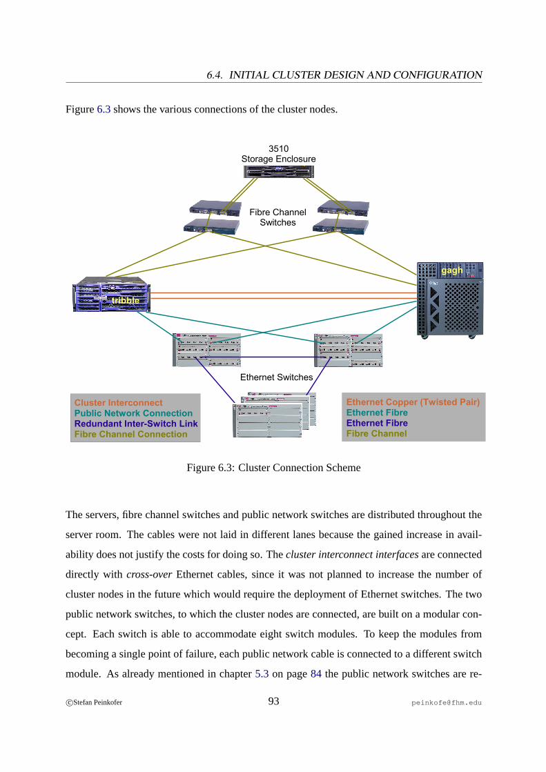
6.4. INITIAL CLUSTER DESIGN AND CONFIGURATION
Figure6.3shows the various connections of the cluster nodes.
Cluster InterconnectPublic Network ConnectionRedundant Inter-Switch LinkFibre Channel Connection
Ethernet Copper (Twisted Pair)Ethernet FibreEthernet FibreFibre Channel
Fibre ChannelSwitches
3510Storage Enclosure
tribble
gagh
Ethernet Switches
Figure 6.3: Cluster Connection Scheme
The servers, fibre channel switches and public network switches are distributed throughout the
server room. The cables were not laid in different lanes because the gained increase in avail-
ability does not justify the costs for doing so. Thecluster interconnect interfacesare connected
directly with cross-overEthernet cables, since it was not planned to increase the number of
cluster nodes in the future which would require the deployment of Ethernet switches. The two
public network switches, to which the cluster nodes are connected, are built on a modular con-
cept. Each switch is able to accommodate eight switch modules. To keep the modules from
becoming a single point of failure, each public network cable is connected to a different switch
module. As already mentioned in chapter5.3 on page84 the public network switches are re-
c©Stefan Peinkofer 93 [email protected]
CHAPTER 6. IMPLEMENTING A HIGH AVAILABILITY CLUSTER SYSTEM USINGSUN CLUSTER
dundantly connected together. Each server is connected to both fibre channel fabrics, so it can
survive a whole fabric failure.
The V440 contains four hot pluggable 74 GB SCSI disks, which are all connected to a single
SCSI controller. This single point of failure cannot be removed, since theSCSI back plane, to
which the disks are connected, provides only a single I/O controller connection. The Enterprise
450 contains three hot pluggable 74 GB SCSI, whereby two are connected to SCSI controllerA
and one is connected to SCSI controllerB. Even though the V440 provides a hardware RAID
option for the local disks, it is not used in order to simplify management, since the Enterprise
450 does not provide such an option and therefore software RAID has to be used to mirror the
boot disks. So it was decided to use software RAID on both servers.
The Enterprise 450 provides three redundant power supplies, but it provides only a single power
connector. So connecting the server to two different main power circuits is not possible and
therefore power connection is a single point of failure on this machine. The V440 provides two
redundant power supplies and each provides a dedicated power connector. This machine is con-
nected to two different main power circuits. Uninterruptible power supplies are not deployed
because of the high maintenance costs for the batteries.
As we have seen, the servers are not completely free of single points of failures. Unfortu-
nately, the ZaK cannot afford to buy other servers. Fortunately, the possibility that a component
which constitutes a single point of failure in these systems will fail is very low, except with the
non-redundant power connection, of course. The single points of failures are accepted because
the costs to remove those points are greater than the benefit of the gained increase in availability.
c©Stefan Peinkofer 94 [email protected]
6.4. INITIAL CLUSTER DESIGN AND CONFIGURATION
6.4.2 Operating System
Except for some special requirements concerning the boot disk partition layout, the operating
system is installed as usual. Every node has to be assigned a hostname and single public net-
work IP address during the installation. The hostname assigned in this step is calledphysical
hostname. The V440 is namedtribble and the Enterprise 450 is namedgagh .
6.4.2.1 Boot Disk Partition Layout
For the boot disk partition layout, there are two design requirements from theSolaris Volume
Manager(SVM), which is used for software mirroring the boot disk, and the Sun Cluster soft-
ware. The SVM requires a small, at least 8 MB large, partition on which thestate database repli-
caswill be stored. The state database replicas contain configuration and state information about
the SVM volumes. The Sun Cluster software requires a partition at least 512 MB large, which
will contain theglobal device files. This partition has to be mounted on/globaldevices .
The global device file system will be exported to all cluster nodes over aproxy file system. This
allows all cluster members to access the devices of all other cluster members. In addition to
that, the global device file system contains an unified disk device naming scheme, which iden-
tifies each disk device, be it shared or non-shared, by a cluster wide unique name. For example
instead of accessing a shared disk on two nodes over two different operating system generated
device names each node can access the shared disk over a common name.
For theroot file systempartition layout, a single 59 GB partition was created. A dedicated
/var partition for log files is not needed because of the more than sufficient size of theroot
partition. For theswap partition, an 8 GB large partition was created. Since the Enterprise 450
has 4 GB memory and the V440 has 8 GB memory, 8 GB swap space should suffice. Table6.1
gives an overview of the partition layout.
c©Stefan Peinkofer 95 [email protected]

CHAPTER 6. IMPLEMENTING A HIGH AVAILABILITY CLUSTER SYSTEM USINGSUN CLUSTER
Slice Tag Mount Point Size
0 root / 59 GB
1 swap swap 8 GB
2 backup na 68 GB
6 usr /globaldevices 1 GB
7 usr na 52 MB
Table 6.1: Boot Disk Partition Layout
6.4.2.2 Boot Disk Mirroring
For the boot disk mirroring, three disks are used. Two are used for mirroring and the third
acts as a hot spare drive. The use of a hot spare drive is not necessarily needed. However, it
is a good idea to have a third drive which contains an additional set of state data replicas, so
using this third disk as a hot spare drive is the obvious procedure. To understand why the third
drive is recommended, we must understand how the Solaris Volume Manager works. To deter-
mine whether and which state database replicas are valid, the SVM uses amajority consensus
algorithm. This algorithm works in the following way:
• The system is able to continue operation when at least the half of the state database
replicas are available/valid.
• The system will issue a kernel panic when less than half of the state database replicas are
available/valid.
• The system cannot boot intomulti-user modewhen the number of available/valid state
database replicas constitutes no quorum2.3
The SVM requires at least three state database replicas. If these three are distributed among
only two disks, the failure of the wrong disk, namely the one which contains two state database
2(boverall number of state database replicas ∗ 0, 5c + 1)3[ANON8] Page 67
c©Stefan Peinkofer 96 [email protected]
6.4. INITIAL CLUSTER DESIGN AND CONFIGURATION
replicas, will lead to a system panic. If four state database replicas are distributed evenly among
the two disks, the failure of one disk will disallow the system from being rebooted without hu-
man intervention. With a third disk and three or six state database replicas distributed evenly
among the disks, a single disk failure will not compromise system operation.
To recover the system, in case the state database replicas cannot constitute a quorum, the system
must be booted intosingle user modeand the unavailable/invalid state database replicas have to
be removed so the available/valid ones can constitute a quorum again.
To mirror the root disk, each of the three disks has to have the same partition layout, since
the Solaris Volume Manager will not mirror the whole disk, but each partition separately. To
be able to mirror a partition, the partitions on the disk have to be first encapsulated in apseudo
RAID 0 volume, also referred to assub mirror. Thereby, each volume has to be assigned a
unique name of the formd<0-127> . Since the mirroring of RAID 0 volumes creates a new
volume which also needs a unique name, the following naming scheme is used to keep track of
the various volumes:
• The number of the mirrored volume begins at10 and is increased by steps of10 for each
additional mirrored volume.
• The first sub mirror which is part of the mirrored volume is assigned the number
< number of mirrored volume > + 1.
• The second sub mirror which is part of the mirrored volume is assigned the number
< number of mirrored volume > + 2.
• The hot-spare sub mirror which is part of the mirrored volume is assigned the number
< number of mirrored volume > + 3.
A special restriction from the Sun Cluster software is that each volume, which contains a
/globaldevices file system or on which a/globaldevices file system is mounted,
c©Stefan Peinkofer 97 [email protected]

CHAPTER 6. IMPLEMENTING A HIGH AVAILABILITY CLUSTER SYSTEM USINGSUN CLUSTER
which is the/ partition in our case, has to be assigned a cluster wide unique volume name.
Tables6.2and6.3give an overview of the boot disk volumes.
Volume Name Type Parts Mount Point
d10 RAID 1 d11 d12 d13 /
d11 RAID 0 c3t0d0s04 na
d12 RAID 0 c3t1d0s0 na
d13 RAID 0 c3t2d0s0 na
d20 RAID 1 d21 d22 d23 swap
d21 RAID 0 c3t0d0s1 na
d22 RAID 0 c3t1d0s1 na
d23 RAID 0 c3t2d0s1 na
d30 RAID 1 d31 d32 d33 /globaldevices
d31 RAID 0 c3t0d0s6 na
d32 RAID 0 c3t1d0s6 na
d33 RAID 0 c3t2d0s6 na
Table 6.2: Boot Disk Volumes V440
4c = Controller ID, t = SCSI Target ID, d = SCSI LUN, s = Slice
c©Stefan Peinkofer 98 [email protected]
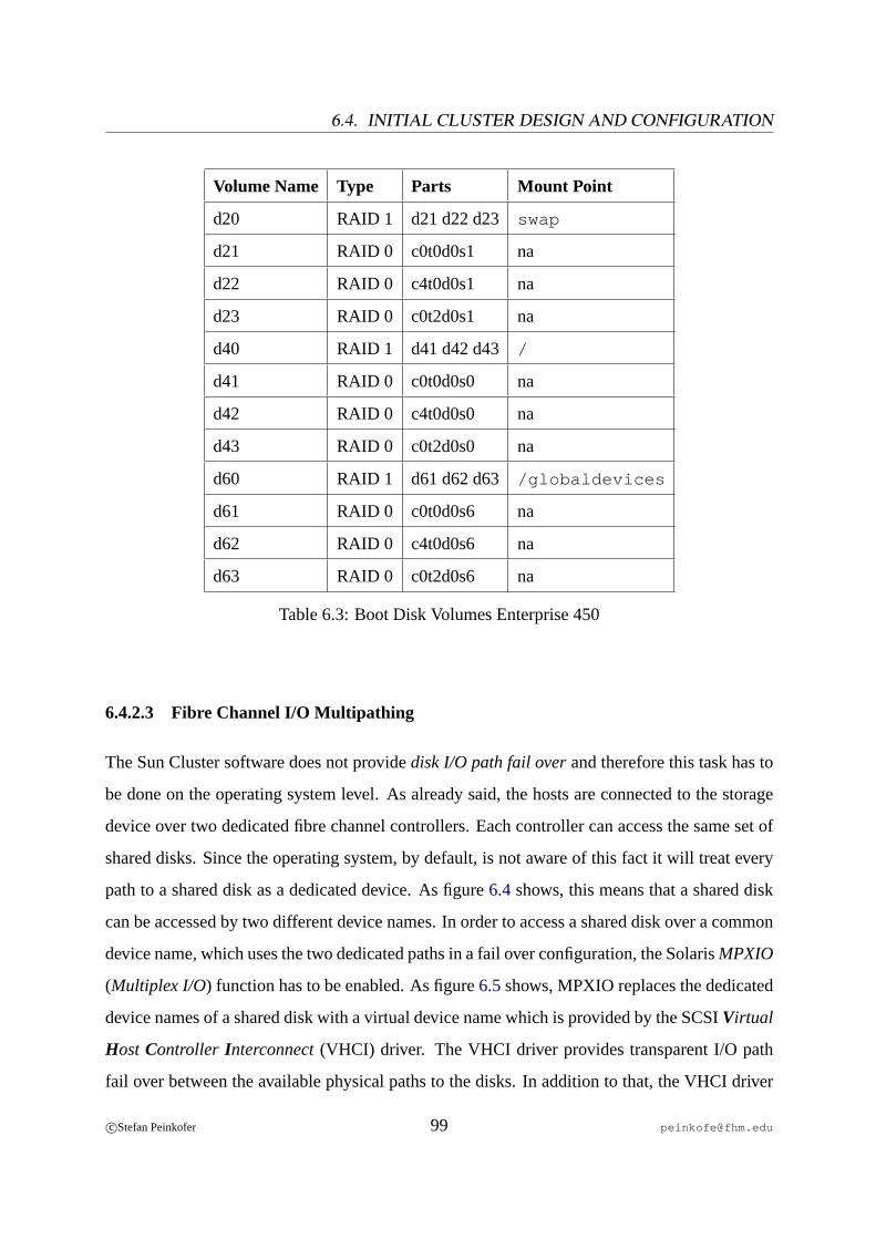
6.4. INITIAL CLUSTER DESIGN AND CONFIGURATION
Volume Name Type Parts Mount Point
d20 RAID 1 d21 d22 d23 swap
d21 RAID 0 c0t0d0s1 na
d22 RAID 0 c4t0d0s1 na
d23 RAID 0 c0t2d0s1 na
d40 RAID 1 d41 d42 d43 /
d41 RAID 0 c0t0d0s0 na
d42 RAID 0 c4t0d0s0 na
d43 RAID 0 c0t2d0s0 na
d60 RAID 1 d61 d62 d63 /globaldevices
d61 RAID 0 c0t0d0s6 na
d62 RAID 0 c4t0d0s6 na
d63 RAID 0 c0t2d0s6 na
Table 6.3: Boot Disk Volumes Enterprise 450
6.4.2.3 Fibre Channel I/O Multipathing
The Sun Cluster software does not providedisk I/O path fail overand therefore this task has to
be done on the operating system level. As already said, the hosts are connected to the storage
device over two dedicated fibre channel controllers. Each controller can access the same set of
shared disks. Since the operating system, by default, is not aware of this fact it will treat every
path to a shared disk as a dedicated device. As figure6.4shows, this means that a shared disk
can be accessed by two different device names. In order to access a shared disk over a common
device name, which uses the two dedicated paths in a fail over configuration, the SolarisMPXIO
(Multiplex I/O) function has to be enabled. As figure6.5shows, MPXIO replaces the dedicated
device names of a shared disk with a virtual device name which is provided by the SCSIVirtual
Host Controller Interconnect(VHCI) driver. The VHCI driver provides transparent I/O path
fail over between the available physical paths to the disks. In addition to that, the VHCI driver
c©Stefan Peinkofer 99 [email protected]
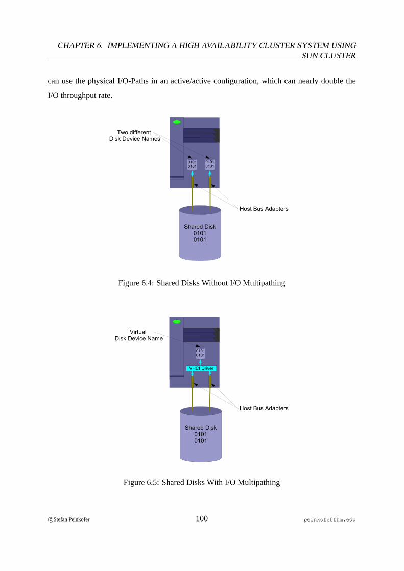
CHAPTER 6. IMPLEMENTING A HIGH AVAILABILITY CLUSTER SYSTEM USINGSUN CLUSTER
can use the physical I/O-Paths in an active/active configuration, which can nearly double the
I/O throughput rate.
Shared Disk01010101
01010101
01010101
Two different Disk Device Names
Host Bus Adapters
Figure 6.4: Shared Disks Without I/O Multipathing
Shared Disk01010101
Virtual Disk Device Name
Host Bus Adapters
01010101
VHCI Driver
Figure 6.5: Shared Disks With I/O Multipathing
c©Stefan Peinkofer 100 [email protected]
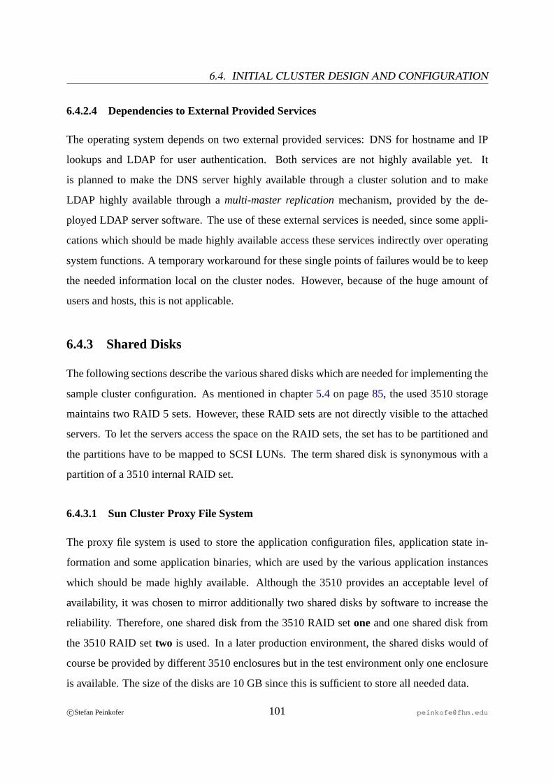
6.4. INITIAL CLUSTER DESIGN AND CONFIGURATION
6.4.2.4 Dependencies to External Provided Services
The operating system depends on two external provided services: DNS for hostname and IP
lookups and LDAP for user authentication. Both services are not highly available yet. It
is planned to make the DNS server highly available through a cluster solution and to make
LDAP highly available through amulti-master replicationmechanism, provided by the de-
ployed LDAP server software. The use of these external services is needed, since some appli-
cations which should be made highly available access these services indirectly over operating
system functions. A temporary workaround for these single points of failures would be to keep
the needed information local on the cluster nodes. However, because of the huge amount of
users and hosts, this is not applicable.
6.4.3 Shared Disks
The following sections describe the various shared disks which are needed for implementing the
sample cluster configuration. As mentioned in chapter5.4 on page85, the used 3510 storage
maintains two RAID 5 sets. However, these RAID sets are not directly visible to the attached
servers. To let the servers access the space on the RAID sets, the set has to be partitioned and
the partitions have to be mapped to SCSI LUNs. The term shared disk is synonymous with a
partition of a 3510 internal RAID set.
6.4.3.1 Sun Cluster Proxy File System
The proxy file system is used to store the application configuration files, application state in-
formation and some application binaries, which are used by the various application instances
which should be made highly available. Although the 3510 provides an acceptable level of
availability, it was chosen to mirror additionally two shared disks by software to increase the
reliability. Therefore, one shared disk from the 3510 RAID setoneand one shared disk from
the 3510 RAID settwo is used. In a later production environment, the shared disks would of
course be provided by different 3510 enclosures but in the test environment only one enclosure
is available. The size of the disks are 10 GB since this is sufficient to store all needed data.
c©Stefan Peinkofer 101 [email protected]

CHAPTER 6. IMPLEMENTING A HIGH AVAILABILITY CLUSTER SYSTEM USINGSUN CLUSTER
6.4.3.2 SUN Shared QFS
For the shared QFS file system, two disks are needed: one large disk, which contains the file
system data and one smaller disk, which contains the file system meta data. The size of the
meta data disk determines how many files and directories can be created on the file system. The
formula for calculating the needed disk size in bytes is as follows:
((number of files + number of directories) ∗ 512) + (16384 ∗ number of directories)
Since it is very difficult to predict how much files and directories will be created in the future,
the space allocated for the meta data was calculated as follows. At the time the home directory
data was migrated to the production QFS, the current number of allocated files and directories
was determined. Based on this data, the currently needed meta data disk size was calculated
and was found to be about 2 GB. This value was multiplied by an estimated growth factor of
5. On the production file system, which the cluster system should overtake someday, the meta
data disk is 10 GB large. This value was taken over for the test system. It is worth mentioning
that additional data and meta data disks can be added to a QFS later on. So when the used data
or meta data runs out of space, additional space can be added easily.
Since the deployed SUN QFS version does not supportvolume manager encloseddisks in a
shared QFS configuration5 it is not possible to mirror the disk between two enclosures, with
software. Because of this and the fact that providing two 1 TB large shared disks is too expen-
sive for the ZaK, mirroring the QFS disks was abandoned.
6.4.4 Cluster Software
The Sun Cluster software can be installed and configured in several ways. It was chosen to
manually install the software on all nodes and to configure the cluster over a text based interface
since this seems to be the least error prone procedure. During the initial configuration, the
following information has to be provided to the cluster system:
5The deployed version is 4.3. After the completion of the practice part, SUN QFS 4.4 was released, which now
supports the use of a volume manager.
c©Stefan Peinkofer 102 [email protected]
6.4. INITIAL CLUSTER DESIGN AND CONFIGURATION
• The physical host names of the cluster nodes.
• The network interface names, which should be used for the cluster interconnect.
• The global device name of the quorum disk.
After the initial configuration, the nodes are rebooted in order to incarnate the cluster for the
first time. After this, various additional configuration tasks have to be performed, to implement
the cluster design.
6.4.4.1 Cluster Time
The initial configuration procedure will automatically create a NTP configuration which will
synchronize the time between all cluster nodes. If the cluster should also synchronize to a time
server, which was true in our case, theserver directive in the NTP configuration file has to
be changed from the local clock to the IP address of the time server.
6.4.4.2 IP Multipathing
A node in a Sun Cluster system is typically connected to two different types of networks, a sin-
gle cluster interconnect networkand one or morepublic networks. For simplification reasons,
we assume in the following that the cluster nodes are connected to only one public network.
Since the cluster nodes are connected to each network over two or more network interfaces,
the failure of a single public network interface should cause the cluster not to fail over the
resource to another node, but just to fail over the assigned IP addresses to another network in-
terface. Also the failure of a single cluster interconnect interface should not cause a split brain
scenario. The way in which this functionality is achieved for the public network is different
from the way for the cluster interconnect. On the public network interfaces, the IP addresses
are assigned to only one physical interface at a time. If this interface fails, the IP addresses
are reassigned to one of the standby interfaces. On the cluster interconnect interfaces, the IP
address is assigned to a special virtual network device driver which bundles the available inter-
faces and uses them in parallel. So if a public network interface fails, clients will experience the
c©Stefan Peinkofer 103 [email protected]
CHAPTER 6. IMPLEMENTING A HIGH AVAILABILITY CLUSTER SYSTEM USINGSUN CLUSTER
network traffic stopping for a short period of time, whereas the failure of a cluster interconnect
interface is completely transparent because the IP is so to speak assigned to all cluster intercon-
nect interfaces at the same time.
Before we can discuss the public network interface fail over process in more detail, we should
first look at the various IP address and host name types, which are used by the cluster system.
• Each cluster node is assigned anode addresson the public network. The host name
assigned to this address is referred to aspublic node name. If a public network interface
fails, this IP address will be failed over to a standby interface. If the cluster node which
is assigned this address fails, this IP will not be failed over to another node. If the cluster
nodes are connected to only one public network, the public node name and node address
refer to the values which were specified for the physical hostname and IP address at
operating system installation time.
• Each cluster node is assigned an IP address on the cluster interconnect network. The host
name assigned to this address is referred to asprivate node name. If a cluster node fails,
this IP address will not be failed over to another node.
• For each resource which provides its services over a public network connection, a ded-
icated IP address is assigned to one of the public network interfaces of the node the re-
source currently runs on. The host name assigned to this address is referred to aslogical
host name. If a public network interface to which such an address is assigned fails, the IP
address will be failed over to a standby interface. Also in case of a node failure, this type
of addresses will be failed over to another node, together with the resource which uses
the IP address.
• Each interface which is connected to a public network is assigned a so-calledtest address.
This IP address will neither be failed over to another local interface, nor be failed over to
another node.
c©Stefan Peinkofer 104 [email protected]

6.4. INITIAL CLUSTER DESIGN AND CONFIGURATION
The Sun Cluster software requires that all IP addresses used on the cluster system are assigned
a unique host name. This host name to IP address mapping has to be defined in the local
/etc/hosts file and in eachname service systemthe cluster nodes use to do IP address res-
olutions.
The functionality for failing over IP addresses, between the public network interfaces is ac-
tually provided by an operating system function called IPMP (IP Multipathing). In contrast to
the MPXIO function, which is completely separated from the cluster software, the Sun Cluster
software and the IPMP function are closely coupled. This means that Sun Cluster subscribes
to the operating systemssysevent notification facilityin order to be notified about events con-
cerning the IPMP function. This allows the cluster to react to IPMP events in an appropriate
manner. For example, if IPMP detects that all public network interfaces on a node have failed,
the cluster system receives the event and will fail over all resources which use IP addresses
assigned to the failed public network connection, to another node.
To use IPMP on a node, first of all a group of two or more public network interfaces, be-
tween which the IP addresses should be failed over, has to be defined. The next step is to
assign a test address to each interface in this group. On these IP addresses, a special flag named
deprecated is set, which prevents any application but IPMP from using the IP address, since
it is not highly available. In the last step, the IP address of the public node name has to be as-
signed to one of the network interfaces in the IPMP group. Further IP addresses, which should
be failed over between the interfaces in the IPMP group, can either be assigned to the same
interface or they can be assigned to different interfaces in the group to distribute the network
load. The IP addresses of the logical host names must not be assigned to the interfaces of the
IPMP groups since the cluster software will do this automatically. Of course, these steps have
to be repeated on each cluster node.
Although the design and configuration of IPMP seems to be simple and straightforward at first
glance, it is found not to be so at further inspection. This is because IPMP behaves uniquely
c©Stefan Peinkofer 105 [email protected]
CHAPTER 6. IMPLEMENTING A HIGH AVAILABILITY CLUSTER SYSTEM USINGSUN CLUSTER
under some circumstances. To understand this, we need to take a closer look at it.
IPMP can detect an interface failure in two ways. The first way is to monitor the network inter-
face driver forlink failure events. The second way is to check the network interfaces actively,
which is done by sending and receiving ICMP echo requests/replies. Therefore the special test
addresses are used. If one of the two failure detection methods indicates a failure, the IP ad-
dresses will be failed over to another network interface in the IPMP group.
By default, IPMP will contact the IP addresses of the default gateway routers for theprobe
basedfailure detection. If no default gateway is specified on the system, it will send an ICMP
echo broadcast at start up and then elect some of the hosts which responded to it as ping hosts.
As long as one of the ping hosts responds to the ICMP echo requests, the corresponding inter-
face is considered healthy, even if another interface in the same group can reach more ping hosts.
If an interface is considered failed, IPMP will set a special flag calledfail on all IP addresses
which are currently assigned to the failed interface. This flag prevents applications from using
these IP addresses to send data. As long as another interface in the IPMP group is considered
healthy, this is no problem since no IP address, except for the test addresses, will be assigned to
the failed interface. If all interfaces of the IPMP group are considered failed, the applications
are not available anymore. Of course, this will trigger a fail over of the resources but under the
following circumstances, a fail over won’t help. In a configuration in which only a single not
highly available default router exists, the failure of the router would cause all public network
interfaces to be considered failed since the router does not respond to the ICMP echo replies
anymore. If all cluster nodes use the same, single default router entry, all cluster nodes are
affected by this router failure and so the public network IPMP groups of all cluster nodes would
be considered failed. This would cause the applications on the cluster to become unavailable,
even to clients which can access the cluster directly, without the router.
Fortunately IPMP provides a method to specify the ping targets manually, by setting static
c©Stefan Peinkofer 106 [email protected]
6.4. INITIAL CLUSTER DESIGN AND CONFIGURATION
host routes to the desired ping hosts. So with this feature, it can be assured that IPMP will not
use a single, not highly available ping target.
On our cluster nodes, four of the most important servers for the cluster are manually speci-
fied as ping nodes.
• Mail server
• LDAP server
• DNS server
• NIS server
6.4.4.3 Shared File System for Application Files
To mirror the two disks designated for the Sun Cluster proxy file system that will contain the
application configuration files, state information files and binaries, the Solaris Volume Manager
is used. In contrast to the local disk mirroring procedure, the mirroring of shared disks is a little
bit more complicated. In addition to that, theshared disk volumesare controlled by the Sun
Cluster software, which is not the case with local disk volumes.
First of all a so-calledshared disk sethas to be created. During creation of the disk set, the
global device names of the shared disks and the physical hostnames of the nodes, which should
be able to access the shared disks, have to be specified. A shared disk set can be controlled by
only one node at a time. This means that only one node can mount the volumes of a disk set
at a time. The node which controls the disk set currently is referred to asdisk set owner. If the
disk set owner is no longer available, ownership of the disk set is failed over by Sun Cluster to
another host which was specified as potential owner at disk set creation time. When the disks
are added to the disk set, they are automatically repartitioned in the following way: The first
few cylinders are occupied by slice 7, which contains the state database replicas. The rest of the
available space is assigned to slice 0. Also, one state database replica is created automatically on
c©Stefan Peinkofer 107 [email protected]
CHAPTER 6. IMPLEMENTING A HIGH AVAILABILITY CLUSTER SYSTEM USINGSUN CLUSTER
slice 7 of each disk. If the disks should not be automatically repartitioned, the partition layout
of the disks must meet the requirement that slice 7 begins at cylinder0 and has sufficient space
to contain the state database replica6. However, for our cluster configuration, this is not required
since all application configuration, state information files and binaries should be placed on one
slice. After the disk set is created, the mirrored volumes can be created by first encapsulating
the appropriate slices in pseudo RAID 0 volumes and then creating RAID 1 volumes which
consist of the appropriate sub mirrors.
Before the RAID 1 volumes can be used, the two cluster nodes must be configured as so-called
mediator hostsof the disk set. While it is easy to understand how the cluster nodes are config-
ured as mediator hosts, this is simply done by calling a single command which takes the name
of the disk set and the physical hostnames of the cluster nodes as command line arguments, it
is hard to understand why and under which circumstances mediator hosts are needed.
The majority consensus algorithm for state database replicas, described in chapter6.4.2.2on
page96, is not applicable to shared disk sets. On shared disk sets, the loss of half of the state
database replicas would render the system already unusable. In configurations in which a failure
of a single component, like a disk enclosure or a disk controller would cause the loss of half
of the state database replicas, this component would be a single point of failure, although it is
redundant. The Sun Cluster documentation calls such configurationsdual disk stringconfigu-
rations, whereby adisk string, in the context of a fibre channel environment, consists of asingle
controller disk enclosure, its physical disks and the fibre channel connections from the enclo-
sure to the fibre channel switches. Since we use a dual controller enclosure and two disks from
two different RAID sets, the failure of a RAID set would cause the described scenario in our
configuration. Therefore we must remove this special single point of failure. To remove such
special single points of failure in general, the Solaris Volume Manager provides two options:
• Provide additional redundancy by having each component threefold, so the failure of a
single component causes only the loss of a third of the state database replicas.
6Usually at least 4 MB.
c©Stefan Peinkofer 108 [email protected]
6.4. INITIAL CLUSTER DESIGN AND CONFIGURATION
• Configure cluster nodes as mediator hosts, which act as additional vote in the case only
half of the state database replicas are active/valid.
Mediator host configurations must meet the following criteria. Unfortunately, the reason why
these rules apply is not documented:
• A shared disk set must be configured with exactly two mediator hosts.
• Only the two hosts which act as mediator hosts for the specific shared disk set are allowed
to be potential owners of the disk set. Therefore only these two hosts can act ascluster
proxy file system serverfor the file systems, contained on the disks within the disk set.
These rules do not mean that the number of cluster nodes is limited to two but only that physical
access to a particular disk set is limited to two of the cluster nodes.
Mediator hosts keep track of the commit count of the state database replicas in a specific shared
disk set. Therefore they are able to decide whether a state database replica is valid or not. Before
we can discuss the algorithm, which is used by the Solaris Volume Manager to decide whether
access to the disks is granted or not, we must first define two terms.
• Replica quorum- It is achieved when more than half of the total number of state database
replicas in a shared disk set are accessible/valid.
• Mediator quorum- It is achieved when both mediator hosts are running and they both
agree on which of the current state database replica commit counts is the valid one.7
The algorithm works as follows.
• If the state database replicas constitute replica quorum, the disks within the disk set can
be accessed. No mediator host is involved at this time.
• If the state database replicas cannot constitute replica quorum, but half of the state database
replicas are accessible/valid and the mediator quorum is met, the disks within the disk set
can be accessed.7[ANON9]
c©Stefan Peinkofer 109 [email protected]
CHAPTER 6. IMPLEMENTING A HIGH AVAILABILITY CLUSTER SYSTEM USINGSUN CLUSTER
• If the state database replicas cannot constitute replica quorum, but half of the state database
replicas are accessible/valid and the mediator hosts cannot constitute mediator quorum
but one of the two mediator hosts is available and the commit counts of the state database
replicas and the mediator host match, the system will call for human intervention to de-
cide whether access to the disk in the disk set should be granted or not.
• In all other cases, access to the disk set is automatically limited to read-only access.8
After the mediator hosts are defined, the proxy file system can be created on the mirrored vol-
umes. This is done by creating an UFS file system as usual and specifying the mount option
global in the /etc/vfstab configuration file. The/etc/vfstab file contains informa-
tion about which disk partition or volume should be mounted to which mount point and which
mount options should be applied. According to the Sun Cluster documentation, the shared file
systems should be mounted under/global/<disk group name>/<volume name>
but actually any mount point which exists on all cluster nodes can be used. Theglobal mount
option defines that the Sun Cluster software should enable the proxy file system feature for the
specified file system. If the specified block device is a volume of a shared disk set, the disk
set owner is automatically also the file system proxy server node. If the current disk set owner
leaves the cluster for some reason, the cluster software will automatically fail over the disk set
ownership and with it the file system proxy task to another node which is configured to be a
potential owner of the particular disk set.
Although all cluster members can access the data on a shared proxy file system, there is a
performance discrepancy between the file system proxy server node and the file system proxy
client nodes. The Sun Cluster software provides the ability to define that the file system proxy
server task should be failed over together with a specific resource group so the applications in
the resource group get the maximum I/O performance on the shared file system. In a scenario
in which application data that is frequently accessed is placed on the proxy file system, such a
configuration is highly recommended.
8[ANON9]
c©Stefan Peinkofer 110 [email protected]
6.4. INITIAL CLUSTER DESIGN AND CONFIGURATION
If more than one resource group requires this feature and the underlying block devices of the
proxy file systems are managed by SVM, a shared disk set has to be created for each resource
group so that the disk ownership, and with it the file system proxy server tasks for the file sys-
tems contained in the disk set, can be failed over independently for each resource group.
For the sample cluster system, the choice was made to use only one common proxy file system
for all application instances since the only data which is frequently changed are the application
log files and the I/O performance of a proxy file system client is considered as sufficient for this
task. One shared disk group nameddg-global-1 was created, which consists of the two 10
GB volumes, described in chapter6.4.3.1on page101. Since the automatic partition feature
was used, the sub mirrors encapsulate slice 0 of the shared disks. The mirror volume is named
d100 and the two sub mirrorsd101 andd102 , according the used naming scheme. The proxy
file system is mounted on/global/dg-global-1/d100 .
6.4.4.4 Resources and Resource Dependencies
This chapter gives a high-level overview of the various resources, resource dependencies and
resource groups which were configured for our cluster system. Based on the requirements, the
cluster should provide three highly available applications. Each application requires a dedicated
IP address and it requires that the global proxy file system is mounted before the application is
started. In addition, NFS and Samba require that the meta data server of the shared QFS file
system is online on the cluster. The needed resources and resource dependencies are shown in
figure6.6.
c©Stefan Peinkofer 111 [email protected]

CHAPTER 6. IMPLEMENTING A HIGH AVAILABILITY CLUSTER SYSTEM USINGSUN CLUSTER
nfs-cl1-rg
ha-user-nfs-home
ha-nfs-appfs smb-cl1-rg
ha-user-smb-home
ha-smb-appfs
radius-cl1-rg
ha-user-radiusd-auth
ha-radius-appfs
qfsclusterfs
ha-nfs ha-smb
ha-radius
ha-qfs
Resource X depends on that Resource Y runs on the same host
Resource X depends on that Resource Y runs somewhere in the cluster
ResourceResource Group
Figure 6.6: Resources and Resource Dependencies on the Sun Cluster
The names of the vertexes are the resource names, whereby theha-user-* resources rep-
resent the application resources, the*-cl1-rg represent the IP address resources and the
ha-*-appfs the resource which ensures that the global proxy file system is mounted. In
addition, there is the special resourceqfsclusterfs , which represents the meta data server
of the QFS shared file system. The green arrows define strong dependencies between the re-
sources, which means the resources have to be started on the same node, whereby the resource
an arrow points to has to be started before the resource the arrow starts from. For the blue ar-
rows, the same is true but it defines a weak dependency, which means that the resource must just
be started somewhere in the cluster. The bright ellipses indicate that the resources contained in
the ellipse form a resource group.
c©Stefan Peinkofer 112 [email protected]

6.4. INITIAL CLUSTER DESIGN AND CONFIGURATION
The default resource group location is as follows:
• V440: ha-nfs , ha-qfs , ha-radius
• E450:ha-smb
This is founded on the following thoughts: The V440 has more than twice the CPU power, that
the E450 has. According to the requirements, NFS and Samba should be run on two different
nodes. Since most of the file serving will be done by NFS, the NFS resource group is placed on
the V440. In addition, the QFS resource group is also placed on the V440 since the host, which
acts as QFS meta data server, has a slight I/O performance advantage. The Radius resource
group is also placed on the V440 because it has more CPU power. However, the CPU power
occupied by Radius is marginal, so it could also be placed on the E450. The Enterprise 450 also
hosts, in addition to the Samba resource group, the proxy file system server by default since
Samba will write the most log file messages to the shared proxy file system.
The creation of resource groups and resources is done by a common command, which basi-
cally takes as arguments:
• whether a resource group or a resource should be created,
• the name of the entity to create,
• dependencies to one or more other resources or resource groups,
• zero or more resource group or resource attributes.
In addition, when creating a resource, the resource type and the resource group, in which the
resource should be created, have to be specified. The resource group and resource attributes
contain values which are either used by the cluster system itself or by the corresponding cluster
resource agent.
c©Stefan Peinkofer 113 [email protected]
CHAPTER 6. IMPLEMENTING A HIGH AVAILABILITY CLUSTER SYSTEM USINGSUN CLUSTER
The common two resource types on which the application resource depend are calledLogi-
calHostnameandHAStoragePlus. The LogicalHostname resource is responsible for assigning
one or more IP addresses to the appropriate public network interfaces. To create a LogicalHost-
name resource, a comma separated list of logical hostnames has to be specified when creating
the resource. Even if the cluster system is connected to more than one public network it is
not necessary to specify the IPMP group to which the IP address should be assigned, since the
resource agent will automatically assign it to the IPMP group which is connected to the appro-
priate public network. The HAStoragePlus resource ensures that one or more file systems are
mounted. In addition to that, it provides the feature of failing over the cluster file system proxy
server task for the specified file systems onto the cluster node on which the HAStoragePlus
resource is started. To create a HAStoragePlus resource, one or more mount points have to be
assigned, in a colon separated list, to the resource propertyFilesystemMountPoints .
6.4.5 Applications
In the following sections we will discuss the design and configuration of the deployed applica-
tions. The application binaries for NFS and SUN QFS are installed through Solaris packages
locally on each host so that rolling upgrades can be performed. Radius and Samba are installed
on the cluster proxy file system, since these applications have to be compiled manually and
so the overhead of compiling each application twice is avoided. To be able to perform rolling
upgrades on the two globally placed applications, a special configuration was applied. On the
global proxy file system, which is mounted on/global/dg-global1/d100 , two directo-
ries were created, one namedslocal-production and the otherslocal-testing . On
both nodes, the directory/usr/slocal is a symbolic link to eitherslocal-production
or slocal-testing . Within the directories, two further directories were created, one named
samba-stuff and the other namedradius-stuff .
To compile and test a new application version,/usr/slocal is linked on one node to
slocal-testing . Then the application is compiled on this node with the install prefix
/usr/slocal/<application>-stuff . After the application is successfully compiled
c©Stefan Peinkofer 114 [email protected]

6.4. INITIAL CLUSTER DESIGN AND CONFIGURATION
and tested, the<application>-stuff directory is copied to theslocal-production
directory and the/usr/slocal link on the node is set back toslocal-production .
6.4.5.1 SUN QFS
The SUN QFS file system is a high performance file system, which can be used as a stand alone
or as an asymmetric shared SAN file system. The SUN QFS cluster agent will make the meta
data server service of a shared QFS highly available, by automatically failing over the meta data
server task to another cluster node, when needed. Additionally the agent will mount the shared
file system automatically on the cluster nodes when they join the cluster.
For the use of SUN QFS as cluster file system, several restrictions exist. First of all it is not
possible to access the file systems from outside the cluster. Second, the meta data traffic has
to travel over the cluster interconnect. Third, although the configuration files must contain the
same information on all nodes, all configuration files must be placed locally on the cluster nodes
in the directory/etc/opt/SUNWsamfs/ . And fourth, all cluster nodes which should be able
to mount the file system must be configured as a potential meta data server.
In order to create a SUN QFS shared file system, first of all, two configuration files have to
be created. The first configuration file, namedmcf contains the file system name and the global
device names of the shared disks for file system data and meta data. The second file, called
hosts.<file system name> , contains a mapping entry for each cluster node, which
should be able to mount the file system. Such an entry maps the physical host name to an IP
address, which the node will use to send and receive meta data communication messages. As
already mentioned, the IP address which has to be specified when QFS is used as a cluster file
system is the address of the cluster interconnect interface. In addition to that, this file provides
the ability to define that a corresponding node cannot become a meta data server. However,
because of the special restrictions for the use of SUN QFS in a cluster environment, this feature
must not be used. After the configuration files are created, the file system can be constructed.
After that, the file system has to be registered in the/etc/vfstab configuration file. In this
c©Stefan Peinkofer 115 [email protected]
CHAPTER 6. IMPLEMENTING A HIGH AVAILABILITY CLUSTER SYSTEM USINGSUN CLUSTER
file the QFS file system must be assigned a mount point and the mount optionshared , which
indicates that the file system is a shared SUN QFS, must be set.
Now, the shared QFS can be registered on the cluster software. First a resource group has
to be created and, after this, the QFS cluster resource has to be registered within the resource
group. During the registration of the QFS resource, thefile system mount pointhas to be speci-
fied. After this, the resource group can be brought online for the first time.
SUN QFS does not depend on an IP address which will be failed over together with the meta
data server, since a special region of the meta data disk contains the information indicating
which node currently acts as meta data server. So a meta data client which wants to mount the
file system looks in this special region to determine which host it has to contact for meta data
operations. In case of a meta data server fail over, the change will be announced to the meta
data clients so they can establish a new connection to the new meta data server.
6.4.5.2 Radius
As Radius server, the open source software Freeradius is deployed. Since no Freeradius Solaris
package is available, the program had to be compiled from source and therefore the application
binaries are placed on the global proxy file system. Also no cluster agent for Freeradius was
available, so a new cluster agent for Freeradius had to be developed. The development of the
agent is discussed in chapter6.5on page123. To deploy Freeradius in conjunction with the clus-
ter agent, the application configuration must meet some special requirements. The Freeradius
cluster agent allows more than one instance of Freeradius to be run; of course, all of these have
to bind to different IP addresses. Therefore, each Freeradius instance needs a dedicated direc-
tory on a shared file system, which contains the configuration files, application state information
and log files of the instance. The name of this instance directory has to be exactly the same as
the cluster resource name of the corresponding Freeradius resource. However, on our cluster,
only one instance is needed. The instance directory is namedha-user-radiusd-auth
and it’s located in the directory/usr/slocal/radius-stuff/ on the cluster proxy file
c©Stefan Peinkofer 116 [email protected]

6.4. INITIAL CLUSTER DESIGN AND CONFIGURATION
system. Inside this directory, the following directory structure has to be created.
1 e t c
2 va r
3 va r / run
4 va r / run / r a d i u s
5 va r / l og
6 va r / l og / r a d i u s
7 va r / l og / r a d i u s / r a d a c c t
After that, the default configuration directoryraddb , which is located in
<specified-install-prefix-at-compile-time>/etc has to be copied to the
ha-user-radiusd-auth/etc directory. Now the configuration can be customized to
meet the respective needs. The general configuration of Freeradius is not further discussed
here. However, some cluster specific configuration changes are needed:
• The configuration directivebind_address has to be set to the IP which will be used
by the Radius resource group as fail over IP address so the Freeradius instance will only
listen for requests on the dedicated IP address
• The configuration directiveprefix has to be set to the application instance directory,
that is/usr/slocal/radius-stuff/ha-user-radiud-auth in our configu-
ration.
• The configuration directiveexec_prefix has to be set to the installation prefix which
was specified at compile time, which is/usr/slocal/radius-stuff in our con-
figuration.
• All public node names configured on the cluster must be allowed to access the Radius
server, to monitor the service. For this, the node names have to be configured as Radius
clients. Since Radius works withshared secret keysto encrypt the password sent between
client and server, all these client entries must be given the same shared secret key.
In the next step, a local user has to be created on each cluster node, which will be used by the
cluster agent to monitor the Freeradius instance. Usually Freeradius will be configured to use
c©Stefan Peinkofer 117 [email protected]

CHAPTER 6. IMPLEMENTING A HIGH AVAILABILITY CLUSTER SYSTEM USINGSUN CLUSTER
one or more remote password backends, either directly or indirectly over the operating system
functions. Even if these backends are highly available, it is recommended to use a local user
for monitoring the service. This is because in a scenario in which the password backend is not
available, the resource would fail consecutively on every cluster node it is failed over to, which
would cause Sun Cluster to put the resource group in a maintenance state to prevent further
ping-pong fail overs. If a resource group is in this maintenance state, it can only brought online
with human intervention again, so even if the password backend becomes available again, the
Radius resource group would remain offline. In contrast to a cluster wide failure of the authen-
tication backend, a situation in which one cluster node can access the password backend and
the other node can’t is very unlikely, since the only likely failure scenario which could cause
such a behavior is the failure of all public network interfaces on a node9 and this will cause a
resource fail over anyway.
In the last step, a file namedmonitor-radiusd.conf has to be created in theetc direc-
tory of the Radius instance directory. In this file the two following values have to be specified:
• RADIUS_SECRET- The shared secret key which should be used by the monitoring func-
tion
• LOCAL_PASSWORD- The password of the local user which was created for the monitor-
ing function
To register the Radius instance on the cluster system, a resource group has to be created. After
this a LogicalHostname resource for the IP address and a HAStoragePlus resource have to be
created, which ensures that the file system that contains the Radius instance directory has been
mounted. After this, the Freeradius resource can be created. To create the Freeradius resource,
the following specialresource parametershave to be set:
• Resource_bin_dir - This is the absoluteinstallation prefix path, with which Freera-
dius was compiled
9We assume here that the password backend is connected to the cluster over the public network.
c©Stefan Peinkofer 118 [email protected]
6.4. INITIAL CLUSTER DESIGN AND CONFIGURATION
• Resource_base_dir - This is the absolute path to the Freeradius instance directory
• Local_username - This is the user name with which the monitoring function will try
to authenticate
• Radius_ld_lib_path - This defines the directories which contain shared libraries,
used by Freeradius
There are several other resource parameters which can be set, but usually don’t have to be be-
cause they are set to reasonable values by default. These additional values are further discussed
in chapter6.5 on page123. In addition to that, it has to be specified that the Radius resource
depends on the HAStoragePlus resource. For the LogicalHostname resource, this does not have
to be specified since the Sun Cluster software implicitly assumes that all resources in a resource
group depend on the IP address resource. After this, the resource group can be brought online
for the first time.
6.4.5.3 NFS
The application binaries needed by NFS are usually automatically installed during the operating
system installation. Configuring NFS as a cluster resource is relatively straightforward. First of
all a directory on a shared file system has to be created. On our cluster it is created on the cluster
proxy file system under/global/dg-global1/d100/nfs . After this, the resource group
has to be created whereby a special resource group property namedPathprefix has to be
set to the created directory on the shared storage. The NFS resource requires that hostname and
RPC (RemoteProcedureCall) lookupsare performed first on the local files before the operating
system tries to contact an external backend like DNS, NIS or LDAP. Therefore, thename service
switchconfiguration, which is located in the file/etc/nsswitch.conf , has to be adopted.
The directivehosts: has to be set to:
cluster files [SUCCESS=return] <external services>
and the directiverpc: has to be set to:
files <external services> .
c©Stefan Peinkofer 119 [email protected]
CHAPTER 6. IMPLEMENTING A HIGH AVAILABILITY CLUSTER SYSTEM USINGSUN CLUSTER
The statement[SUCCESS=return] defines that no external services should be queried if
the corresponding entry is found in the local files. This statement is only needed for the
hosts: directive, since it is already the default setting for therpc: directive. The next
step is to create a directory namedSUNW.nfs within the directory which was specified as
Pathprefix during resource group creation. Within theSUNW.nfs directory a file named
dfstab.<resource name> has to be created, whereby<resource name> is the name
which will be assigned to the NFS resource. On our cluster, the file is named
dfstab.ha-user-nfs-home . Thedfstab file contains the configuration of which di-
rectories are to be shared with which hosts. For the share configuration, the following special
restrictions apply:
• The hostnames of the cluster interconnect interfaces must not have access to the NFS
service.
• All hostnames which are assigned to public network interfaces of the cluster must have
read/write access to the NFS service. Also, it turned out that these hostnames must be
specified twice, once with thefull qualified domain nameand once with the bare host-
name.
After this, the LogicalHostname and the HAStoragePlus resource can be created within the re-
source group. The last step is to create the NFS resource, whereby only the dependencies to the
HAStoragePlus and the QFS resource have to be specified during creation.
It is worth mentioning that the NFS resource uses theSUNW.nfs directory not only for the
dfstab configuration file, but also for state information, which enables the NFS program
suite to perform NFS lock recovery in case of a resource fail over. The core NFS program
suite consists of three daemons,nfsd , lockd andstatd , wherebynfsd is responsible for
file serving,lockd is responsible for translating NFS locks, acquired by clients into local file
system locks on the server andstatd keeps track of which clients have currently locked files.
If a client locks a file,statd creates a file underSUNW.nfs/statmon/sm which is named
like the client hostname which acquired the lock. If the NFS service is restarted,statd looks
c©Stefan Peinkofer 120 [email protected]
6.4. INITIAL CLUSTER DESIGN AND CONFIGURATION
in the SUNW.nfs/statmon/sm directory and notifies each hostname for which a file was
created in the directory to re-establish all locks the client held prior to the server restart.
6.4.5.4 Samba
Like Radius, Samba, the windows file serving application for UNIX, has to be compiled from
source and therefore the application binaries are placed on the cluster proxy file system. Since
the Samba cluster agent provides the ability to run multiple Samba instances on the cluster, each
instance requires a dedicated directory on a shared file system to store configuration files, appli-
cation state information and log files. The names of these directories can be chosen freely. For
our cluster, it was chosen to use theNetBIOSname of the Samba instance (SMB-CL1-RG) as in-
stance directory name. The directory was created under
/usr/slocal/samba-stuff/SMB-CL1-RG . Within the instance directory, the follow-
ing subdirectory structure has to be created.
1 l i b
2 l o g s
3 n e t l o g o n
4 p r i v a t e
5 s h a r e s
6 va r
7 va r / l o c k s
8 va r / l og
After this, the Samba configuration filesmb.conf has to be created in thelib directory of
the instance directory. The general configuration of Samba is not further discussed here, but
again some cluster specific configuration settings have to be applied which are listed as follows:
• interface - Must be set to the IP address or hostname of the dedicated IP address for
the Samba resource group.
• bind interfaces only - Must be set to true so thatsmbd and nmbd, the core
daemons of the samba package, only bind to the IP address specified by theinterface
directive.
c©Stefan Peinkofer 121 [email protected]

CHAPTER 6. IMPLEMENTING A HIGH AVAILABILITY CLUSTER SYSTEM USINGSUN CLUSTER
• netbios name - Must be set to the NetBIOS name of the dedicated IP address, speci-
fied by theinterface directive.
• log file - Specifies the absolute path to thesamba.log file, which should be located
under<instance-directory>/var/log/samba.log
• lock directory - Specifies the absolute path to the lock directory, which should be
located under<instance-directory>/var/locks
• pid directory - Specifies the absolute path to the pid directory, which should be
located under<instance-directory>/var/locks
• private dir - Specifies the absolute path to the Samba private directory, which should
be located under<instance-directory>/private
After this, a local user has to be created, which will be used by the monitor function of the cluster
agent to test Samba. This user has to be created as a UNIX account and as a Samba account.
Also a subdirectory has to be created within one of the directories, which will be shared by
Samba. Ownership of this subdirectory must be set to the newly created monitor user. In the
next step, the Samba resource group, the LogicalHostname and HAStoragePlus resources have
to be created. After that, a special configuration file, used by the Samba resource agent, has to
be created. In this configuration file, the following information has to be provided:
• RS- The name of the Samba application resource which should be created.
• RG- The name of the resource group in which the Samba application resource should be
created.
• SMB_BIN- The absolute path to the Sambabin directory.
• SMB_SBIN- The absolute path to the Sambasbin directory.
• SMB_INST- The absolute path to the Samba instance directory.
• SMB_LOG- The absolute path to the Samba instance log directory.
c©Stefan Peinkofer 122 [email protected]
6.5. DEVELOPMENT OF A CLUSTER AGENT FOR FREERADIUS
• SMB_LIB_PATH- A list of directories which contain shared libraries, used by Samba.
• FMUSER- The username of the local user which was created for the monitor function.
• FMPASS- The password of the monitor user.
• RUN_NMBD- Specification of whether the Samba resource uses the NetBIOS daemon
nmbd or not.
• LH - Specification of the IP address or hostname which was configured by the
interface directive in thesmb.conf file.
• HAS_RS- Specification of the resources on which the Samba resource depends.
The last step is to call a special program, provided by the Samba cluster agent, which will regis-
ter the Samba resource on the cluster, based on the information in thecluster agent configuration
file.
6.5 Development of a Cluster Agent for Freeradius
In the following sections we will look at the development of a cluster agent for the Freeradius
application. The Sun Cluster software provides various ways and extensive APIs to implement
a cluster agent. To discuss all of them would go beyond the scope of this thesis and therefore
we will look only at the particular topics which were necessary to build the Freeradius cluster
agent. Before we can discuss the concrete implementation of the agent, we must first look at
how a cluster agent interacts with the cluster software.
6.5.1 Sun Cluster Resource Agent Callback Model
The Sun Cluster software defines a fixed set ofcallback methods, which will be executed by the
cluster software under well defined circumstances. The cluster software also defines which tasks
the individual callback methods require the cluster agent to do, which arguments are provided
to the cluster agent and which return values are expected from the cluster agent. To implement a
c©Stefan Peinkofer 123 [email protected]
CHAPTER 6. IMPLEMENTING A HIGH AVAILABILITY CLUSTER SYSTEM USINGSUN CLUSTER
cluster agent, a dedicatedcallback functionprogram has to be written for each callback method,
whereby a cluster agent is not required to implement all defined callback methods. A cluster
agent for Sun Cluster does not consist of a single executable but of various executables which
implement a specific callback function. The callback functions can either be implemented inC
programsor in executable shell scripts.
To define which callback function the cluster software should call for carrying out a particu-
lar callback method, a so-calledResourceTypeRegistration(RTR) file has to be created, which
must contain among other things a mapping between callback method and callback function.
In the following section, we will look briefly at the defined callback methods.
• Prenet_start - This method is called before the LogicalHostname resources in the same
resource group are started. This can be used to implement special start-up tasks which
have to be carried out before the IP addresses are configured.
• Start - This method is called when the cluster software wants to start the resource. This
function must implement the appropriate procedure to start the application and it must
only return successfully if the application was successfully started.
• Stop - This method is called when the cluster software wants to stop a resource. This
function must implement the appropriate procedure to stop the application and must only
return successfully if the application was successfully stopped.
• Postnet_stop- This method is called after the LogicalHostname resource in the same
resource group is stopped. This can be used to implement special stop tasks which have
to be carried out after the IP addresses are unconfigured.
• Monitor_start - This method is called when the cluster software wants to start the re-
source monitoring. This function must start the monitor program for the particular appli-
cation and must only return successfully if it succeeds in starting the resource monitoring
program.
c©Stefan Peinkofer 124 [email protected]
6.5. DEVELOPMENT OF A CLUSTER AGENT FOR FREERADIUS
• Monitor_stop - This method is called when the cluster software wants to stop the re-
source monitoring. This function must stop the monitor program and must only return
successfully if the monitoring program is stopped.
• Monitor_check - This method is called when the cluster software wants to determine
whether the resource is runnable on a particular hosts. This function must perform the
needed steps to predict whether the resource will be runnable on the node or not.
• Validate - This method is called on any hosts which is configured to be able to run the
resource, when:
– a resource of the corresponding type is created
– resource propertiesof a resource of the corresponding type are changed
– resource group propertiesof a group which contains a resource of the corresponding
type are updated.
Since the function is called before the particular action is carried out, this function is not
used to test the new configuration but to do a basic sanity check of the environment on
the nodes.
• Update - This method is called by the cluster software to notify a resource agent when
resource, resource groupor resource type propertiesare changed. This function should
implement the appropriate steps to reinitialize the resource with the new properties.
• Init - The cluster software will call this function on all nodes which are potentially able
to run the resource, when the resource is set to themanaged state by the administrator.
Themanaged state defines that the resource is controlled by the cluster software, which
means for example that the resource can be brought online by an administrative command.
It also means that the cluster software will automatically bring the resource online on the
next node which joins the cluster. This function can be used to perform initialization tasks
which have to be carried out when the resource becomes managed.
c©Stefan Peinkofer 125 [email protected]
CHAPTER 6. IMPLEMENTING A HIGH AVAILABILITY CLUSTER SYSTEM USINGSUN CLUSTER
• Fini - The cluster software will call this function on all nodes which are configured to
be able to run the resource, when the resource is set to theunmanaged state by the
administrator. This function can be used to perform clean up tasks which have to be
carried out before a resource becomes unmanaged.
• Boot - If the resource is inmanaged state, the cluster software will call this function on
a node which is configured to be able to run the resource, when the node joins the cluster.
This function can be used to perform initialization task which have to be carried out when
a node joins the cluster.
The Sun Cluster software requires that the callback functions forStop, Monitor_stop, Init ,
Fini , Boot andUpdateare idempotent. Except for theStart andStopmethods, which must be
implemented by the cluster agent, all other methods are optional.
6.5.2 Sun Cluster Resource Monitoring
As we saw in the previous chapter, Sun Cluster defines no direct callback method for resource
monitoring, i.e. it does not call the monitoring function directly and evaluates the return value of
the function to determine whether the resource is healthy or not. Instead it defines two callback
methods to start and stop the monitoring. This means that a cluster agent, which should perform
resource monitoring, must implement aProbe function, which is started and stopped by the two
callback methods and which continuously monitors the application in the configured interval.
In addition to that, theProbe function must be able to initiate the appropriate actions when the
probe failed, i.e. it must first decide whether the application should be restarted or failed over
and second it must trigger the appropriate action by itself.
6.5.3 Sun Cluster Resource Agent Properties
The Sun Cluster software defines a set ofresource type propertiesand resource properties
which are used to specify the configuration of a cluster agent. The values or default values
respectively for the properties are specified in the Resource Type Registration file of the cluster
c©Stefan Peinkofer 126 [email protected]

6.5. DEVELOPMENT OF A CLUSTER AGENT FOR FREERADIUS
agent. Resource type properties specify general attributes which are common for all resources
of the specific type. Resource properties specify attributes which can be different for each
resource of the specific type. In addition to the predefined set of resource properties, the cluster
agent developer can define additional resource properties which contain special configuration
attributes for the agent. In the following two sections we will look at some important resource
type properties and resource properties.
6.5.3.1 Resource Type Properties
The most important resource type properties are the “callback methodto callback function“
mapping properties, which were already discussed in chapter6.5.1on page123. Besides that,
the following important resource type properties exist:
• Failover - Defines whether the resource type is a fail over or a scalable resource. A
fail over resource cannot be simultaneously online on multiple nodes, whereas a scalable
resource can. Scalable resources are typically deployed when Sun Cluster is used as a
Load Balancing or High Performance Computing cluster.
• Resource_type - Defines the name of the resource type.
• RT_basedir - Defines the absolute path to the directory, to which the resource agent is
installed.
• RT_version - Defines the program version of the cluster agent.
• Single_instance - If this property is set to TRUE, only one resource of this type can
be created on the cluster.
• Vendor_ID - Defines the name of the organization which created the cluster agent.
The syntax for defining resource type properties in the RTR is as follows:
<property-name> = <value>;
c©Stefan Peinkofer 127 [email protected]

CHAPTER 6. IMPLEMENTING A HIGH AVAILABILITY CLUSTER SYSTEM USINGSUN CLUSTER
6.5.3.2 Resource Properties
• <Callback Method>_timeout - Defines the time in seconds the
<Callback Method> is allowed run until the cluster considers the execution of the
corresponding callback function failed.
• Resource_dependencies - Takes a comma separated list of resources in the same
or in another resource group, on which the resource depends.
• Resource_name - The name of the resource. This value is specified when a new
resource is created.
• Retry_count - The number of times theProbe function should try to restart the re-
source before it triggers a fail over.
• Retry_interval - This defines the time span, beginning with the first restart attempt,
after which therestart retrycounter will be reset.
• Thorough_probe_interval - Defines the time interval in seconds which should
elapse between two resource monitor sequence invocations.
In contrast to the resource type properties, a resource property is defined by one or more re-
source property attributes. The most important resource property attributes are:
• Default - The default value for the resource property
• Min - The minimum allowed value for a resource property of the data typeInteger .
• Max - The maximum allowed value for a resource property of the data typeInteger .
• Minlength - The minimum allowed length of a resource property of the data type
String or Stringarray .
• Maxlength - The maximum allowed length of a resource property of the data type
String or Stringarray .
c©Stefan Peinkofer 128 [email protected]
6.5. DEVELOPMENT OF A CLUSTER AGENT FOR FREERADIUS
• Tuneable - This attribute specifies under which circumstances the administrator is al-
lowed to change the value of the resource property. Legal values are:
– NONE- The value can never be changed.
– ANYTIME- The value can be changed at any time.
– AT_CREATION- The value can only be changed when a resource is created.
– WHEN_DISABLED- The value can only be changed when the resource is in disabled
state.
To definecustom resource properties, the special resource property attributeExtension and
one of the following resource property attributes which define the data type of the custom re-
source property have to be specified:
• Boolean
• Integer
• Enum
• String
• Stringarray
The syntax for defining resource properties in the RTR is as follows:
{
PROPERTY = <property name>;
<resource property attribute>; | <resource property attribute>
= <attribute value>;
...
<resource property attribute>; | <resource property attribute>
= <attribute value>
}
c©Stefan Peinkofer 129 [email protected]
CHAPTER 6. IMPLEMENTING A HIGH AVAILABILITY CLUSTER SYSTEM USINGSUN CLUSTER
6.5.4 The Sun Cluster Process Management Facility
All processes which will be started by the callback functions should run under the control of
theProcessManagementFacility (PMF). The PMF continuously checks to determine whether
the application process or at least one of its child processes is alive. If not, it restarts the ap-
plication. To start an application instance under the control of PMF, a special command has to
be called to which the command to start the application has to be assigned as an argument. To
identify an application instance which was “created“ under the control of PMF, aunique iden-
tifier tag has to be specified as argument, when calling the PMF to start an application. Since
it is not desirable for PMF to restart an application indefinitely, the resource property values of
Retry_count andRetry_interval are also specified as arguments.
Besides the process control, PMF provides some other functions to the callback functions. For
example a callback function can send a signal to all processes of an application instance by
calling the PMF, specifying the identification tag of the application instance and the signal to
send to the processes.
6.5.5 Creating the Cluster Agent Framework
Creating a comprehensive cluster agent from scratch is very complex and time consuming be-
cause various callback functions have to be implemented and a comprehensive understanding
of how Sun Cluster requires a cluster agent to be written is needed. Fortunately, the Cluster
Software provides a Graphical User Interface, with which a cluster agent can be created. This
wizard allows even a person with virtually no experience in programming to create a cluster
agent in two steps. In the first step, the values for the resource type propertiesVendor_ID ,
Resource_type , RT_version andFailover have to be specified and the user has to
choose whether the agent programs will be “written“ as aC or a Kornshellprogram. In the
second step, the commands to start and stop the applications and an optional command which
will carry out the application health check have to be specified. The only requirement for these
commands is that they return 0 if they are successful and a value other than 0 if they are not.
c©Stefan Peinkofer 130 [email protected]
6.5. DEVELOPMENT OF A CLUSTER AGENT FOR FREERADIUS
In addition to that, for each of the three callback methods, adefault timeouthas to be specified,
which is assigned as the default of the corresponding<Callback Method>_timeout re-
source property. After that, the wizard will create the needed source and configuration files,
compile the sources if necessary and create a Solaris installation package.
Although the creation of a cluster agent by using the wizard is very easy, it has one major
drawback. The wizard provides no facility to pass any resource or resource type properties to
the commands for starting, stopping and checking the applications. This means:
• If the agent should be deployed on another cluster, it is required that the commands be
installed to the same path to which they were installed on the original system.
• Only one resource of this type can be created on the cluster because the location of the
instance directory which contains the configuration, log and application state information
files is “hard coded“.
However, these restrictions do not render the wizard useless, since the created source files can
be used as a framework which can be manually adapted to the actual requirements.
6.5.6 Modifying the Cluster Agent Framework
One primary goal for the development of the Freeradius cluster agent was that it should be
reusable on other cluster systems and that it should provide the ability to deploy more than one
Freeradius resource on one cluster. Therefore, thecluster agent creation wizardwas used to
create the needed source files, which were manually extended by the needed functionality to
make it freely configurable. To do so, the following callback functions had to be adopted:
• Start
• Validate
In addition to that, theProbe function had to be adopted, which is responsible for calling the
health check program in regular intervals to determine whether the resource is healthy and if
c©Stefan Peinkofer 131 [email protected]
CHAPTER 6. IMPLEMENTING A HIGH AVAILABILITY CLUSTER SYSTEM USINGSUN CLUSTER
this is not the case, to react in the appropriate manner.
For theStart callback function, the following resource extension properties were defined in
the RTR file:
• Radiusd_bin_dir - This value defines the absolute path to the directory which con-
tains the Radius application binary.
• Resource_base_dir - This value defines the absolute path to the directory which
will contain the instance directory of the Radius resource.
• Radiusd_ld_lib_path - This value defines a list of directories which contain shared
libraries, used by the Radius application.
The functional extension of theStart callback function is that it determines the values of the
three resource extension properties and uses them to assemble the start command. Instead of
calling:
/usr/slocal/radius-stuff/bin/radiusd -d \
/usr/slocal/radius-stuff/etc/raddb
which would start the Freeradius application and tell it that the configuration files are found in
the directory which was specified after the-d parameter, it will now call:
<Radiusd_bin_dir>/radiusd -d \
<Resource_base_dir>/<Resource_name>/etc/raddb .
The path specified by<Resource_base_dir> was not directly used as instance directory,
since this property is assigned a default value and there is no way to force a value assigned
to an extension property to be unique throughout all resources of the same type. So when
more than one Freeradius resource is created on the cluster, the creator could forget to specify
a different value for the property and, therefore, both resources would use the same instance
directory which could lead to random side effects. Therefore it was chosen to force the re-
source creator to create a unique instance directory by using the resource name, which has to
c©Stefan Peinkofer 132 [email protected]
6.5. DEVELOPMENT OF A CLUSTER AGENT FOR FREERADIUS
be unique throughout the cluster as the name for the instance directory. The directories speci-
fied by<Radiusd_ld_lib_path> are passed as command line argument to the PMF call
which executes the start command. This causes the PMF to assign the directories to the en-
vironment variableLD_LIBRARY_PATHin the environment in which PMF will call the start
command so thedynamic linkerwill also include these directories to search forshared libraries.
The Validate function, created by the cluster agent creation wizards, checks to determine
whether the application start command exists and is an executable file. The function was ex-
tended like theStart callback function, and instead of checking whether the file:
/usr/slocal/radius-stuff/bin/radius
exists and is executable, it checks the file which is specified by:
<Radiusd_bin_dir>/radiusd
The other checks of theValidate function need not be adapted.
For theProbe function, the following resource extension properties were defined:
• Probe_timeout - Defines the time in seconds the health check program is allowed to
run until theProbe function considers the execution of the health check program failed.
This extension property is actually defined by the cluster agent creation wizard.
• Radius_port - The TCP port on which the Radius daemon listens for incoming re-
quests.
• Radius_dictionary - This allows the user to specify a path to an alternateRadius
Dictionary file, which the health check program should use to communicate with the
Radius daemon.
• Login_attempts - This defines how many times the health check program tries to
authenticate against Radius before it considers the Radius instance unhealthy.
c©Stefan Peinkofer 133 [email protected]

CHAPTER 6. IMPLEMENTING A HIGH AVAILABILITY CLUSTER SYSTEM USINGSUN CLUSTER
• Local_username - This defines the username the health check function will use to
authenticate against Radius.
• Radius_secrets_file - This defines the absolute path to a file which contains the
password of theLocal_username and the Radius secret which will be used to encrypt
the password before it is sent to the Radius daemon. It was chosen to place this informa-
tion in a external file, to which only privileged users have access, rather than put it in the
cluster configuration since the resource properties can also be read by unprivileged users.
• RFC_user_password - This defines whether the health check program should use
User-Password, which is suggested by the Radius RFC, orPassword, which is currently
expected by the Freeradius application, as “password command“ in the Radius network
protocol.
• Probe_debug - This defines whether the health check program should do extensive
logging or not.
• SCDS_syslog - This defines the absolute path to theSun ClusterData Service syslog
program the health check application will use to submit log messages.
Except for theProbe_timeout property, the values of these properties are not used by the
Probe function directly but are passed to the program which carries out the actual application
health check, which is discussed in the next section. In addition to these values, the hostname
of the cluster node the resource is currently running on is passed to the health check program,
too.
The complete source of the Radius cluster agent can be found on the CD-ROM which is de-
livered along with this document.
6.5.7 Radius Health Checking
For the health check of the Freeradius application, it was chosen to perform a Radius authentica-
tion of a local user. Although the Freeradius program suite provides a Radius client application,
c©Stefan Peinkofer 134 [email protected]

6.6. USING SUN QFS AS HIGHLY AVAILABLE SAN FILE SYSTEM
this application cannot be used as a health check application because it reports failures only by
printing an error message tostderr but not by setting the exit code to a value other than 0.
Another health check program was needed because of this fact.
The health check program used for the Radius resource agent is an adopted version of a mon-
itoring script provided by the Open Source service monitoring toolmon. The check program
is written in PERL by James Fitz Gibbon and it is based upon Brian Moore’s Radius monitor
script, posted to the mon mailing list. The program was adopted to meet the special require-
ments of the Freeradius daemon and the requirements of the Sun Cluster environment.
6.6 Using SUN QFS as Highly Available SAN File System
Although Sun supports the deployment of a shared SUN QFS file system inside a cluster as
a cluster file system, Sun does not support the deployment of it as ahighly available SAN file
system, which would allow computers from outside the cluster to access the file system asmeta
data clients. For the ZaK there are two main reasons why the use of a shared SUN QFS as
highly available SAN file system, in addition to the use as cluster file system, is desirable:
1. Ability to do LAN-less backup. Doing a full backup of one TB data over the local area
network cannot be finished within a adequate time span. Since the backup system of the
ZaK is also connected to the storage area network, the obvious solution is to back up the
data directly over the SAN. Therefore, the backup system, which cannot be part of the file
serving cluster because it is a dedicated cluster, managed by an external company, must
be able to mount thehome directory file system.
2. Increased I/O performance. Some services, which run on servers outside the cluster, have
currently mounted the home directories over NFS. If these servers could mount the home
directory file system natively asshared file system meta data clients, they would benefit
from the increased I/O performance.
c©Stefan Peinkofer 135 [email protected]
CHAPTER 6. IMPLEMENTING A HIGH AVAILABILITY CLUSTER SYSTEM USINGSUN CLUSTER
Unfortunately, using a shared SUN QFS as cluster file system and highly available SAN file
system is not only unsupported but also is not possible without applying special workarounds.
For this, basically three challenges have to be accomplished. In the following chapters we will
discuss these challenges and the possible ways to accomplish them.
6.6.1 Challenge 1: SCSI Reservations
6.6.1.1 Problem Description
The Sun Cluster software uses SCSI reservations to fence failed nodes from the shared storage
devices. Which reservation method, SCSI-2 or SCSI-3, the cluster software uses is automati-
cally determined by the cluster software in the following way: For each shared disk, which is
connected to exactly two cluster nodes, SCSI-2 reservations are used. For shared disks which
are connected to more than two cluster nodes, SCSI-3 persistent group reservations are used.
This behavior is “hard wired“ and cannot be overwritten by a configuration parameter. A shared
QFS meta data client needs at least read/write access to the shared disk(s) which contain(s) the
file system data and read access to the shared disk(s) which contain(s) the file system meta data.
The read access to the meta data disks is needed to read the file system super block that contains
the information regarding which host currently acts as meta data server.
Our cluster system consists of two nodes. This implies that the cluster software uses SCSI-2
reservations for fencing. As long as both cluster nodes are up, servers outside of the cluster
can access the shared disk, since the disks are not reserved. If one cluster node goes down, the
remaining node will reserve all shared disks, so the servers outside of the cluster cannot access
the file system anymore.
6.6.1.2 Possible Solutions
For the SCSI reservation problem, three possible solutions were found. Solution one is rela-
tively straightforward. The Sun Cluster software allows the administrator to set a special flag
called LocalOnly on a shared disk. This flag causes the cluster software to exclude the
c©Stefan Peinkofer 136 [email protected]

6.6. USING SUN QFS AS HIGHLY AVAILABLE SAN FILE SYSTEM
disk from the fencing operation. If all disks which are used by the shared QFS are marked as
LocalOnly , the servers outside of the cluster will be able to access the shared file system
even if only one cluster node is up. However, this course is potentially dangerous and may lead
to a corruption of the file system. A shared QFS does not require that the data and meta data
disks be fenced in case a meta data client which has mounted the file system fails. However, it
requires that if the server, which acted as the file system meta data server, fails, it be fenced off
the meta data disk before another server can take over the meta data server task. If the shared
QFS file system is deployed outside of a cluster, this is done by human intervention and if it is
deployed inside a cluster it is done by the fencing mechanism. So the discussed solution cannot
eliminate the possibility that a failed cluster node, which acted as meta data server, accesses the
meta data disks, after the task was taken over by another cluster member.
The second and third solutions are a little bit more complex than the first one. In addition
they require at least a three-node cluster, since they rely on SCSI-3 persistent group reserva-
tions. To understand them, we have to discuss how Sun Cluster uses SCSI-3 persistent group
reservations for shared disk fencing. The principles of SCSI-3 persistent group reservations
were already discussed in chapter3.2.7on page28. The Sun Cluster software uses the de-
scribedWRITE EXCLUSIVE / REGISTRANTS ONLYreservation type. This allows any server
which is attached to the disk to access the shared disk on a read-only basis and it allows write
access only to those servers which are registered on the shared disk. Registering means that a
node puts a unique 8-byte key on a special area on the disk, by issuing a special SCSI command.
The key is created by the Sun Cluster software as follows: The first 4 bytes contain thecluster
ID, which was created by the cluster software during the first time configuration process. The
next 3 bytes are zero and the last byte contains thenode IDof the corresponding cluster node.
The node ID is a number between 1 and 64 and indicates the sequence in which the cluster
nodes were installed. To fence a failed cluster node from the disks, the cluster software on the
remaining cluster nodes computes theregistrationof the failed node and removes it10 from the
shared disks by a special SCSI-3 command. If the failed node joins the cluster again, the cluster
10And with it the reservation, if held by the node.
c©Stefan Peinkofer 137 [email protected]
CHAPTER 6. IMPLEMENTING A HIGH AVAILABILITY CLUSTER SYSTEM USINGSUN CLUSTER
software on the node places its registration key on the shared disks again.
Solution two is basically the same idea of solution one, applied to a SCSI-3 persistent group
reservation environment. As already said theWRITE EXCLUSIVE / REGISTRANTS ONLYpre-
vents only write access to a shared disk from unregistered servers, and servers from outside the
cluster must only have read-only access to the meta data disk. So theLocalOnly flag has
only been applied to the shared disk(s) which contain(s) the file system data. In this config-
uration, it is assured that a failed meta data server node is fenced off the meta data disks and
since the shared QFS does not require that a server is fenced off the file system data disks, file
system consistency is ensured. With this solution, a virtually unlimited number of cluster exter-
nal servers can access the file system and in addition to that, the servers can run any operating
system which is supported by QFS11.
Although solution two seems to be sufficient, there is one imponderability. Although a QFS
meta data client should not need write access to the file system meta data disks in theory, it is
nowhere explicitly documented that it does not need write access in practice, too. So it cannot
be ruled out that a QFS meta data client will try to write to the shared meta data disks for some
special reason. The third solution goes a completely different way; instead of excluding disks
from the SCSI-3 persistent group reservation, it includes the servers outside of the cluster in the
SCSI-3 persistent group reservation. Therefore, a small application is needed, which registers
the external server to the shared disks, used by SUN QFS. This application must be executed
on any external host which should access the file system, since SCSI-3 registrations can only
be removed by another node but not added for another node. Since SCSI-3 reservations are
persistent, which means they survive power cycles of servers and storage and the Sun Cluster
software will only remove the keys of failed cluster members from the shared disks to fence
a cluster node off the shared disks, this step has to carried out only once when a new server
is added to the shared QFS file system. To eliminate the imponderability that a reservation is
lost for some reasons, the registration application could also be called every time before the
11Which is currently only Solaris and a few Linux distributions.
c©Stefan Peinkofer 138 [email protected]

6.6. USING SUN QFS AS HIGHLY AVAILABLE SAN FILE SYSTEM
shared QFS file system is mounted on the node since multiple reservations of a server are not
possible. Unfortunately no freely available application which is able to place SCSI-3 persistent
group reservations on shared disks exists. Although such an application is delivered with the
Sun Cluster software, it cannot be used since it is tightly integrated with the cluster software
and works only on a cluster node which is a member of a quorum cluster partition. Fortunately,
Solaris provides a well documented programming interface namedmultihost disk control inter-
face. By using this interface, such an application can be created easily.
With this solution, the servers outside of the cluster have full read/write access to all shared
disks used by QFS. This simulates exactly the conditions which exist on a shared SUN QFS
which is deployed outside of a cluster. In addition to that, the fencing mechanism of the cluster
is not impacted since all shared disks are included in the fencing operation. However, the over-
all count of servers which can access the file system is limited to 64 because SCSI-3 persistent
group reservations can handle only 64 registrants. In addition to that, the application which reg-
isters a server can only be used on Solaris, since the used programming interface is not available
on other operating systems. If operating systems other than Solaris should be able to access the
file system, a new SCSI reservation application has to be found or written.12
6.6.2 Challenge 2: Meta Data Communications
6.6.2.1 Problem Description
As described in section6.4.5.1on page115, the meta data communication between cluster
nodes has to travel over the cluster interconnect network. This restriction is in effect because
of the following reason: The QFS resource agent makes only the QFS meta data server service
highly available and therefore only monitors the function of the meta data server. What is left
completely unaddressed by the QFS resource is the surveillance of whether a meta data client
12Since QFS currently only supports Solaris and Linux, I did an Internet search for a Linux version of such an
application. What I found was the sg3_utils, a set of applications which use functions provided by the Linux SCSI
Generic Driver. Unfortunately I cannot say whether these tools work since during my tests, I had no success in
placing a SCSI-3 reservation on a shared disk. But this may be because I used the tool in the wrong way.
c©Stefan Peinkofer 139 [email protected]

CHAPTER 6. IMPLEMENTING A HIGH AVAILABILITY CLUSTER SYSTEM USINGSUN CLUSTER
is able to communicate with the meta data server or whether the meta data server is able to
communicate with all meta data clients in the cluster. This functionality is implicitly achieved
by using the cluster interconnect as meta data interconnect, since all members of the quorum
cluster partition are always able to communicate with each other over the cluster interconnect.
If the meta data communication travelled over network interfaces other than the cluster inter-
connect interfaces, the failure of all these interfaces on a cluster node would either prevent the
node from accessing the file system or prevent all other nodes from accessing the file system, de-
pending upon whether the node was a meta data client or meta data server. Of course, if a node
were not able to access the file system anymore, the resources which depend on the file system
would be failed over to another node because the monitor function of these resources would fail.
If the interfaces failed on the meta data server, all services which depend on the file system
would be failed over to the meta data server, since it is the only node which is able to access
the file system anymore. In a two-node cluster, this behavior is in principle no problem, but
we should keep in mind that the resources are failed over to the node which actually caused the
problem, so this behavior should not be desirable. In a 2+N node cluster or if external servers
should be able to access the file system, this behavior is not desirable because the meta data
server service should be failed over to another node so that all nodes, except the one which
caused the problem, are able to access the file system again.
Since dedicated physical network interfaces cannot be used for meta data communication be-
tween the cluster nodes, the obvious solution would be to connect the external servers to the
cluster interconnect network. However, this is not possible either, since the Sun Cluster soft-
ware requires that only cluster nodes are connected to the cluster interconnect network.
6.6.2.2 Possible Solutions
As we have seen, the fundamental problem with meta data communication is that cluster nodes
must use the cluster interconnect for sending and receiving meta data messages and cluster ex-
c©Stefan Peinkofer 140 [email protected]
6.6. USING SUN QFS AS HIGHLY AVAILABLE SAN FILE SYSTEM
ternal hosts must not use the meta data interconnect for this. So to get around this restriction,
the host which currently acts as meta data server should be able to send and receive meta data
communications over more than one IP address. This would provide the ability to use the cluster
interconnect network for sending and receiving meta data messages to/from cluster nodes and
to use a public network for sending and receiving meta data messages to/from cluster external
nodes. Fortunately, SUN QFS provides such a feature by simply mapping a comma separated
list of IP addresses to the corresponding physical hostname of the node, in thehosts.<file
system name> configuration file.
SUN recommends for cluster external shared QFS file systems that meta data messages be sent
over a dedicated network. To provide highly available meta data communication between the
potential meta data servers within the cluster and the cluster external meta data clients, at least
two redundant cascaded switches are needed and each cluster node and external node must be
connected by two network interfaces to the switches so that interfaceA is connected to switch
A and interfaceB is connected to switchB.
To provide local interface IP address fail over, an IPMP group consisting of the two meta data
network interfaces has to be defined on each cluster and external node. Additionally, each of
the newly created IPMP groups is assigned an IP address which will be failed over between
the corresponding local interfaces of the group. This IP addresses have to be added to the
hosts.<file system name> to tell QFS that it should also use these addresses for meta
data communication.
As discussed in section6.6.2.1on 139, if the meta data communication does not travel over
the cluster interconnect but over a normal network connection, the failure of this network con-
nection on the current meta data server would prevent the meta data client hosts from being able
to access the file system. Since the meta data network, which connects the cluster nodes with
the cluster external hosts together, is a normal network connection, special precautions have to
be taken so that the cluster system can appropriately respond in case all interfaces in the meta
c©Stefan Peinkofer 141 [email protected]
CHAPTER 6. IMPLEMENTING A HIGH AVAILABILITY CLUSTER SYSTEM USINGSUN CLUSTER
data IPMP group of the current meta data server fail. What is meant by “appropriately respond“
is fail over the meta data server task to a cluster node which still has connectivity to the external
meta data network. To achieve this behavior, a LogicalHostname resource has to be created
within the resource group which contains the QFS resource. The IP address which is assigned
to the LogicalHostname resource must be from the same subnet as the meta data network IP
addresses are from, so the resource will assign the IP address to the meta data IPMP group.
Now, when all interfaces of the meta data IPMP group fail on the current meta data server, the
LogicalHostname resource will fail and therefore the resource group, which contains the Log-
icalHostname resource and the QFS resource, will be failed over to a cluster node whose meta
data IPMP group is healthy.
As discussed in section6.4.4.2on page103IPMP will set the special flagfail on IP addresses,
assigned to a failed interface. When all interfaces in the meta data IPMP group have failed,
whereby failed can mean that just the elected ping nodes are not reachable, this can become a
problem. As long as another cluster node exists whose meta data IPMP group is not considered
failed this is no problem. But maybe all cluster nodes have automatically selected the same
set of ping nodes. In this case, the meta data server service would become unavailable to the
external hosts. In order to prevent this scenario, the ping nodes have to be specified manually
on the cluster nodes. Basically, there are three options which will result in the desired cluster
node behavior and will keep the IPMP group from being considered failed because of a “false
alarm“ caused by the IPMP probe based failure detection mechanism:
• All external meta data client hosts are configured as ping targets of the cluster nodes. In
doing so, the IPMP probe based failure detection will only consider an IPMP group failed
if all external meta data clients hosts are not reachable. The advantage of this method
is that it actually monitors the logical connectivity to the external meta data client hosts.
The drawback of this option is that the IPMP ping host configuration has to be adopted
each time a new external meta data client is configured.
• Each cluster node is configured to use only its own IPMP test addresses as ping nodes.
c©Stefan Peinkofer 142 [email protected]
6.6. USING SUN QFS AS HIGHLY AVAILABLE SAN FILE SYSTEM
This method simply bypasses the IPMP probe based failure detection mechanism since
the IPMP test addresses of the local interfaces are always available. The drawback of this
method is that only physical connection failures can be detected.
• If the network switches, deployed in the meta data network, are reachable through an IP
address13, the addresses of the switches to which the cluster nodes are directly connected
can be used as ping targets. This is based on the thought that a switch which no longer
responds to a ping request has a problem and, therefore, the IP address should be failed
over to another interface, which is connected to another switch. The advantage of this
option is that the IPMP ping host configuration does not have to be adopted if a new
external meta data client is configured.
The external meta data client hosts are configured to use only the IP address, provided by the
LogicalHostname resource in the QFS resource group as ping node. Since this IP is always
hosted by the current meta data server, this configuration is the best case solution since a path
is only considered failed when the meta data server host cannot be reached over that path.
6.6.3 Challenge 3: QFS Cluster Agent
6.6.3.1 Problem Description
The QFS cluster agent implements the two optional callback methodsValidate and
Monitor_check which both will validate the QFS configuration file
hosts.<file system name> . The methods will fail if not all “physical hostnameto
meta data IP address“ mappings in the file are according the following syntax:
<public network hostname> <cluster interconnect IP of the node>
Since the syntax of thehosts.<file system name> does not meet this criteria anymore,
because an additional IP address was specified after the cluster interconnect IP to solve chal-
lenge 2, the two functions will fail. To understand the effects of this failure, we will look a little
closer at these callback functions.13For example to provide a configuration interface over the network.
c©Stefan Peinkofer 143 [email protected]

CHAPTER 6. IMPLEMENTING A HIGH AVAILABILITY CLUSTER SYSTEM USINGSUN CLUSTER
• Validate - The Validate function is called on any host which potentially can run this
resource, when a resource is created or when resource or resource type attributes are
changed by the administrator. The failure of theValidate method will prevent the re-
source from being created or the property from being updated.
• Monitor_check - The Monitor_check function is called on a host to which the cluster
system wants to fail over the resource, to determine whether the resource will be runnable
on that particular host. Unfortunately it is not documented in which cases this function is
called exactly. By observing the cluster system, the following could be determined: When
a node failure, a failure of the QFS meta data server resource or a manual relocation
of the resource with a special administrator command caused the resource relocation,
theMonitor_check command was not executed. The only failure scenario in which an
execution of theMonitor_check function could be observed was the failure of a resource
on which the QFS meta data server resource depends. Since an IP address resource was
added to the QFS resource group, on which the QFS resource implicitly depends, a failure
of the meta data IPMP group would keep the QFS resource from failing over because the
Monitor_check function was called and failed.
6.6.3.2 Possible Solutions
Since both theValidate andMonitor_check functions of the QFS cluster agent are binary ex-
ecutable files, the only possible solution to solve this problem is to replace the two functions.
This can be done in either of two ways.
The first and easiest way is to replace just the two executable files for theValidate and the
Monitor_check functions. The disadvantage of this solution is that applying a patch for the
SUN QFS file system will overwrite the replaced files and so the files will have to be replaced
every time the QFS file system is patched.
The second way is to tell the cluster system to use other callback functions for theValidate
c©Stefan Peinkofer 144 [email protected]

6.6. USING SUN QFS AS HIGHLY AVAILABLE SAN FILE SYSTEM
andMonitor_check methods. Unfortunately the two values cannot be changed by simply call-
ing an administrative command. To change the values, the QFS cluster agent resource type
registration file has to be changed. To let the changes come into effect, the QFS resource type
has to be newly registered within the cluster system. If it was not registered before, this is no
problem. If it was, the resource type must be first unregistered which means that every resource
of this type has to be removed as well. The advantage of this method is that the changes remain
in effect even when the QFS file system is patched.
Since it is hard to determine which tasks the two callback functions would carry out, the re-
placed files do nothing but pass a return value of 0 (OK) back. For theValidate method,
this means that newly created QFS resources and resource type property or resource property
changes should be deliberate and require extensive testing. For theMonitor_check method,
this means that in the special case that the meta data server task is failed over to a node, which
is really not capable of running the resource, the fail over process takes a little bit longer. This
is because the cluster system will not notice that the resource is not able to run on that host until
the Start method or theMonitor method fails. But since the likelihood of such a scenario is
reasonably small, this risk can be tolerated.
6.6.4 Cluster Redesign
The following sections describe the redesign of the sample cluster implementation in order to
use the SUN QFS as highly available SAN file system.
6.6.4.1 Installation of a Third Cluster Node
To solve the SCSI reservation challenge, it was chosen to implement the solution which uses
SCSI-3 persistent group reservations in conjunction with a special program which registers an
external meta data client host on the SUN QFS disks to gain read/write access to them.
As already said, this solution requires a three-node cluster since Sun Cluster will use SCSI-2
c©Stefan Peinkofer 145 [email protected]

CHAPTER 6. IMPLEMENTING A HIGH AVAILABILITY CLUSTER SYSTEM USINGSUN CLUSTER
reservations on a two-node cluster. Since the cluster interconnect of our cluster is implemented
as two direct cross-over network connections, the cluster interconnect had to be reconfigured to
use network switches so an additional cluster node can be connected to the cluster interconnect
network. This task is relatively easy and can be done in a rolling upgrade manner. First, one
cluster interconnect path is removed from the cluster configuration; after this, the correspond-
ing network interfaces are connected to the first switch; and then the cluster configuration is
updated to use the new path. After this, the same procedure is carried out for the remaining
cluster interconnect paths.
To save hardware costs, it was decided to use the two switches for the cluster interconnect
network as well as for the meta data network for the external meta data clients. Figure6.7
shows the reconfigured cluster interconnect and meta data network.
TrunkedInter-Switch Link
gagh
tribble
Cluster Interconnect VLAN Meta-Data VLAN
Physical Network InterfaceVirtual Network InterfaceVirtual Network Interface
Node 3
EthernetSwitches
Figure 6.7: Cluster Interconnect and Meta Data Network Connection Scheme
c©Stefan Peinkofer 146 [email protected]

6.6. USING SUN QFS AS HIGHLY AVAILABLE SAN FILE SYSTEM
Since Sun Cluster requires that the cluster interconnect is a dedicated network, to which only
cluster nodes have access, twotagged, port based VLANsare configured on each switch, one
for the cluster interconnect network and one for the meta data network. As figure6.7 shows,
switch ports which connect cluster nodes are assigned to bothtagged VLANsand the other ports
are assigned only to the tagged VLAN for the meta data network.
Tagged VLANs provide the ability to partition a physical network into several logical networks
which are identified by aVLAN ID. To designate a switch port as a member of a VLAN, the
corresponding VLAN ID is assigned to that port, whereby it is possible to assign more than one
VLAN ID to a single port. If a port is a member of more than one VLAN, which are assigned
asuntagged VLANsto the port, it seems for the attached host that all traffic comes and goes to a
single network. If the VLANs are assigned as tagged VLANs, all Ethernet packets are assigned
a MAC header extensionwhich contains the corresponding VLAN ID. Since the attached host
is not aware of this header extension by default, these packets are dropped until a special vir-
tual VLAN network interfacewhich is aware of the VLAN ID extension field, is defined. To
configure the VLAN interface, the VLAN ID of the VLAN, which the interface should use to
send and receive data, has to be specified. So on our cluster nodes, two virtual VLAN inter-
faces, one for the cluster interconnect and one for the meta data network are configured upon
each physical interface which is connected to one of the two switches. So although a common
physical connection is used, for the cluster software and the other applications it looks like two
dedicated networks exist.
After the cluster interconnect network was reconfigured, the third cluster node was installed.
Figure6.8shows the adopted connection scheme of the cluster.
c©Stefan Peinkofer 147 [email protected]
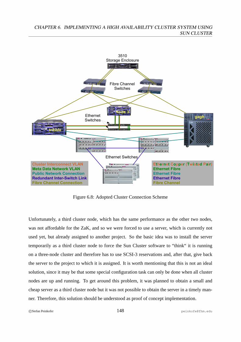
CHAPTER 6. IMPLEMENTING A HIGH AVAILABILITY CLUSTER SYSTEM USINGSUN CLUSTER
Cluster Interconnect VLANMeta Data Network VLANPublic Network ConnectionRedundant Inter-Switch LinkFibre Channel Connection
Ethernet Copper (Twisted Pair)Ethernet FibreEthernet FibreEthernet FibreFibre Channel
Node 3gagh
Fibre ChannelSwitches
3510Storage Enclosure
EthernetSwitches
Ethernet Switches
tribble
Figure 6.8: Adopted Cluster Connection Scheme
Unfortunately, a third cluster node, which has the same performance as the other two nodes,
was not affordable for the ZaK, and so we were forced to use a server, which is currently not
used yet, but already assigned to another project. So the basic idea was to install the server
temporarily as a third cluster node to force the Sun Cluster software to “think“ it is running
on a three-node cluster and therefore has to use SCSI-3 reservations and, after that, give back
the server to the project to which it is assigned. It is worth mentioning that this is not an ideal
solution, since it may be that some special configuration task can only be done when all cluster
nodes are up and running. To get around this problem, it was planned to obtain a small and
cheap server as a third cluster node but it was not possible to obtain the server in a timely man-
ner. Therefore, this solution should be understood as proof of concept implementation.
c©Stefan Peinkofer 148 [email protected]
6.6. USING SUN QFS AS HIGHLY AVAILABLE SAN FILE SYSTEM
Since the third cluster node couldn’t be used as a “real“ cluster node, only a small subset of
the discussed configuration tasks which are necessary for the cluster node to join the cluster
was performed. This subset consisted of the following tasks:
• Connect the third cluster node to the SAN.
• Install the operating system without mirroring the boot disk.
• Install the cluster software.
• Configure for the first time the cluster software on the third node.
At the point when the third node joins the cluster for the first time, the cluster updates the
global device databaseand uses SCSI-3 persistent group reservations for every shared disk
which can be accessed by all three cluster nodes, which in our case are all shared disks since
the third cluster node is connected to the same SAN zone as the others. After the third node was
installed and joined the cluster, the vote count of the quorum disk had to be adjusted, since now,
four possible votes were available in the cluster: three from the cluster nodes and one from the
quorum disk. To achieve that even a single node can constitute a quorum if it owns the quorum
device, three votes are needed and so the quorum disk must be assigned a vote count of two.
This is done by removing and then reassigning the quorum device from or respectively to the
cluster configuration. Now the cluster assigns the quorum device automatically a vote count of
two. After this, the third node was brought offline and given back to the project to which it was
assigned.
6.6.4.2 Meta Data Network Design
As already said, it was chosen to use the two switches for the cluster interconnect network also
for the meta data network. The basic difference between the cluster interconnect network and
the meta data network is that the meta data network, which uses IPMP for making the network
connections highly available, requires that the two switches are connected together since the
meta data server could listen on an interface which is connected to switchA and an external
c©Stefan Peinkofer 149 [email protected]
CHAPTER 6. IMPLEMENTING A HIGH AVAILABILITY CLUSTER SYSTEM USINGSUN CLUSTER
meta data client could listen on an interface which is connected to switchB. In order to provide
a redundant inter-switch link, the switches are connected together by two paths, which are used
in a trunkingconfiguration, i.e. the switches will utilize both connections simultaneously. Since
these inter-switch connections are only required for the meta data network, the inter-switch links
are configured to forward only the traffic of themeta data network VLAN.
After this, the LogicalHostname resource was created within the QFS resource group. As IPMP
ping targets of the cluster nodes, it was chosen to use the IP addresses of the two switches. The
decision is based on the thought that maintaining a list of all external meta data clients is too
error prone, since adding a new external meta data client to the list can be easily overseen.
In the last step, the QFS configuration filehosts.<file system name> was adopted,
so that each cluster node bound the meta data server to itscluster interconnect IPand itsmeta
data network IP.
6.6.4.3 QFS Cluster Agent Reconfiguration
To get around the restrictions of the QFS cluster agent, it was chosen to change the resource type
configuration not to use the original callback functions but to use the replacements. Since the
QFS cluster agent was already configured on the cluster and, therefore, the QFS resource type
was already configured, the resource type had to be unregistered. Therefore, all resources had
to be brought offline and set to the unmanaged state. Then, the resource dependencies between
QFS and the NFS and the Samba resources had to be deleted. After this, the QFS resource had
to be deleted. Finally, the QFS resource type could be unregistered. In the next step, the QFS
resource type configuration was adopted so that theValidate and Monitor_Check callback
methods pointed to the void replacement callback functions. After this, the resource type was
registered again, the QFS resource was created and the dependencies between the QFS resource
and the NFS and Samba resources were re-established.
c©Stefan Peinkofer 150 [email protected]
Chapter 7
Implementing a High Availability Cluster
System Using Heartbeat
7.1 Initial Situation
The databases for the telephone directory and the Identity Management System are currently
hosted on two x86 based servers. The server which hosts the Identity Management System
database runs Red Hat Linux 9, which is no longer supported by Red Hat. The server which
hosts the telephone directory database runs Fedora Core 2 Linux. The databases are currently
located on local SCSI disks. The Identity Management System database is placed on a hardware
RAID 5 of four disks and the telephone directory database is placed on a software RAID 1 of
two disks.
7.2 Customer Requirements
The requirements of the new system are to provide a reference implementation of a high avail-
ability cluster solution, using two identical x86 based servers, Red Hat Enterprise Linux 4 as
operating system and Heartbeat 2.x as cluster software. On this cluster system, the two Post-
greSQL databases for the Identity Management System and the telephone directory should be
made highly available in anactive/activeconfiguration.
151
CHAPTER 7. IMPLEMENTING A HIGH AVAILABILITY CLUSTER SYSTEM USINGHEARTBEAT
Since Heartbeat 2.0.0 was released only a few weeks before the cluster system was created,
the main purpose of this cluster system is to evaluate whether the latest Heartbeat version1 at
that time is already reliable enough to be deployed on a production system.
7.3 General Information on Heartbeat Version 2
Heartbeat is a typicalFail Over cluster. Although Heartbeat supports that more than one in-
stance of a particular resource is online simultaneously through so-calledresource clones, it
provides no functions for load balancing or high performance computing. So the use of these
resource clones is very limited.
Heartbeat supports two types of cluster interconnects:
• Ethernet
• Serial Interfaces
Since Heartbeat exchanges heartbeats over the TCP/IP protocol, it is highly recommended to
use a serial connection in addition to the Ethernet based cluster interconnects so that a split
brain scenario, caused by a failure of the TCP/IP stack, is avoided.
Heartbeat uses noquorum tie breaker, like a quorum disk. This is mainly caused by the fact that
the Linux kernel provides poor and unreliable support for SCSI-2 and SCSI-3 reservations. The
Heartbeat developers are currently deliberating about usingping nodesas quorum tie breakers
but this solution is still under design. Because of the poor SCSI reservation support, Heartbeat
also cannot use SCSI reservation for fencing and so it has to use STONITH. Since no quorum
tie breaker is available, Heartbeat ignores quorum in a two-node configuration. To prevent the
two nodes from “STONITHing“ each other simultaneously, one of the two nodes is given a
head start. Which node is given the head start is negotiated between the two cluster nodes each
time a node joins the cluster.1Which was 2.0.2 during this thesis.
c©Stefan Peinkofer 152 [email protected]
7.4. CLUSTER DESIGN AND CONFIGURATION
7.3.1 Heartbeat 1.x vs. Heartbeat 2.x
To understand the desire to use Heartbeat 2.x on the cluster system, we must briefly look at the
differences between Heartbeat version 1 and 2.
• The maximum number of cluster nodes is limited to two in version 1, whereas it is vir-
tually unlimited in version 2. At the time of this writing version 2 has been successfully
tested with 16 nodes.
• Heartbeat version 1 monitors only the health of the other cluster node, but not the re-
sources which run on the cluster. Therefore version 1 provides onlynode level fail over.
Heartbeat version 2 deploys a resource manager which can call monitoring functions to
determine whether a resource is healthy or not and can react to a resource failure in the
appropriate way. So version 2 provides alsoresource level fail over.
• With Heartbeat version 1 it is only possible to define a single resource group for each
cluster node. Heartbeat version 2 provides the ability to define a virtually infinite number
of resource groups.
So the feature set of Heartbeat version 2 meets the requirements on a modern high availability
cluster system whereas version 1 lacks some fundamental features.
7.4 Cluster Design and Configuration
In the following sections we will discuss the design of the Heartbeat cluster system.
7.4.1 Hardware Layout
To build the cluster, two identical dual CPU servers were available. The required external
connections the server had to provide are as follows:
• 2 network connections for the public network.
• 1 network connection for the cluster interconnect.
c©Stefan Peinkofer 153 [email protected]
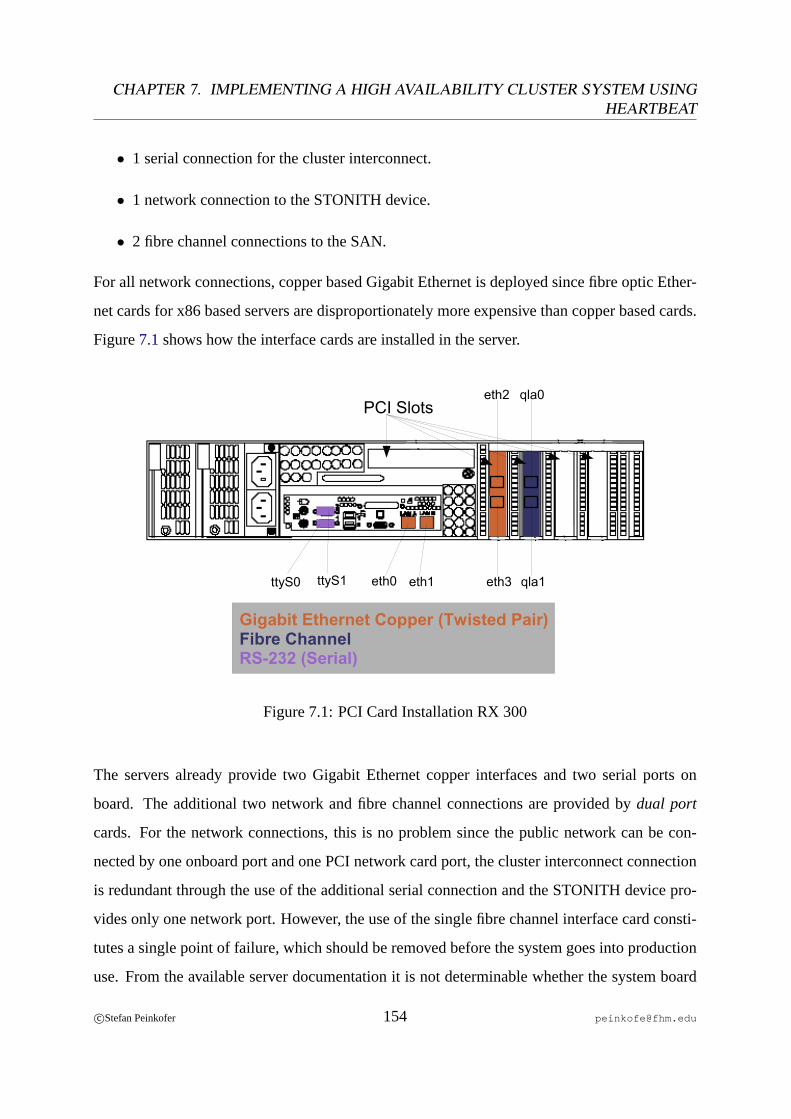
CHAPTER 7. IMPLEMENTING A HIGH AVAILABILITY CLUSTER SYSTEM USINGHEARTBEAT
• 1 serial connection for the cluster interconnect.
• 1 network connection to the STONITH device.
• 2 fibre channel connections to the SAN.
For all network connections, copper based Gigabit Ethernet is deployed since fibre optic Ether-
net cards for x86 based servers are disproportionately more expensive than copper based cards.
Figure7.1shows how the interface cards are installed in the server.
eth0 eth1 eth3
eth2 qla0
qla1
Gigabit Ethernet Copper (Twisted Pair)Fibre ChannelRS-232 (Serial)
ttyS0 ttyS1
PCI Slots
Figure 7.1: PCI Card Installation RX 300
The servers already provide two Gigabit Ethernet copper interfaces and two serial ports on
board. The additional two network and fibre channel connections are provided bydual port
cards. For the network connections, this is no problem since the public network can be con-
nected by one onboard port and one PCI network card port, the cluster interconnect connection
is redundant through the use of the additional serial connection and the STONITH device pro-
vides only one network port. However, the use of the single fibre channel interface card consti-
tutes a single point of failure, which should be removed before the system goes into production
use. From the available server documentation it is not determinable whether the system board
c©Stefan Peinkofer 154 [email protected]
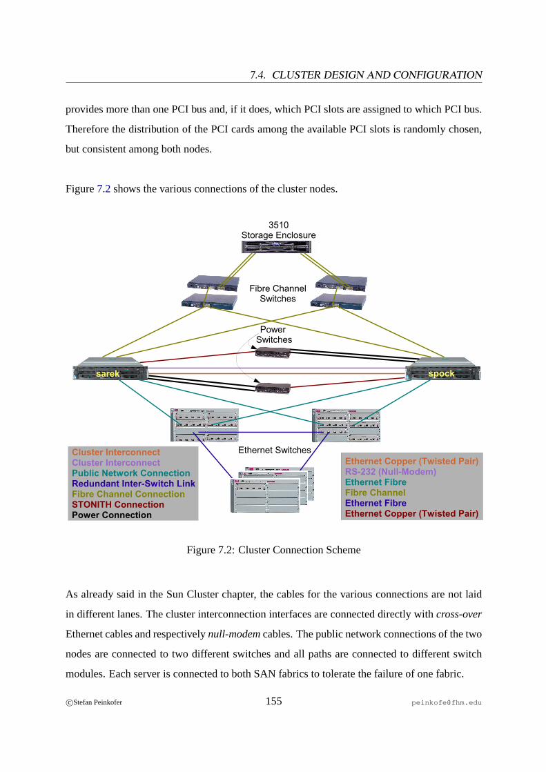
7.4. CLUSTER DESIGN AND CONFIGURATION
provides more than one PCI bus and, if it does, which PCI slots are assigned to which PCI bus.
Therefore the distribution of the PCI cards among the available PCI slots is randomly chosen,
but consistent among both nodes.
Figure7.2shows the various connections of the cluster nodes.
Cluster InterconnectCluster InterconnectPublic Network ConnectionRedundant Inter-Switch LinkFibre Channel ConnectionSTONITH ConnectionPower Connection
Ethernet Copper (Twisted Pair)RS-232 (Null-Modem)Ethernet FibreFibre ChannelEthernet FibreEthernet Copper (Twisted Pair)
Fibre ChannelSwitches
3510Storage Enclosure
Ethernet Switches
sarek spock
Power Switches
Figure 7.2: Cluster Connection Scheme
As already said in the Sun Cluster chapter, the cables for the various connections are not laid
in different lanes. The cluster interconnection interfaces are connected directly withcross-over
Ethernet cables and respectivelynull-modemcables. The public network connections of the two
nodes are connected to two different switches and all paths are connected to different switch
modules. Each server is connected to both SAN fabrics to tolerate the failure of one fabric.
c©Stefan Peinkofer 155 [email protected]

CHAPTER 7. IMPLEMENTING A HIGH AVAILABILITY CLUSTER SYSTEM USINGHEARTBEAT
Each server contains 6 hot pluggable 147 GB SCSI disks, which are all connected to a sin-
gle SCSI controller. This single point of failure cannot be removed, since the SCSI back plane
provides only a single I/O controller connection. Although the servers were purchased with a
hardware RAID controller option, this RAID controller cannot be used. This is because the
RAID controller option is realized by a relatively new technology calledZero Channel RAID.
A traditional RAID controller combines theSCSI controllerandRAID controller task in one
logical unit, i.e. the disks are directly connected to the RAID controller. In a Zero Channel
RAID configuration, the disks are connected to a typical SCSI controller which is placed on
the motherboard and the RAID controller is installed to a special PCI slot. This provides the
advantage that the RAID functionality can be upgraded without recabling the disk connections.
However, at the time the cluster was set up, no driver for the purchased Zero Channel RAID
controller was available for Red Hat Enterprise Linux 4. In addition to that, the results of a per-
formance test, using a Linux distribution which provides drivers for this controller showed that
the performance of the Zero Channel RAID controller is inferior to the performance of software
RAID. So it was chosen to abandon and uninstall the Zero Channel RAID controller.
The servers provide two redundant power supplies whereby each power supply is connected
to a different main power circuit. As on the Sun Cluster, no uninterruptible power supplies are
deployed because of the maintenance costs.
7.4.2 Operating System
For the installation of the operating system, no special requirements exist. Every node is as-
signed aphysical hostnameand a public network IP address as usual. On our Heartbeat cluster,
the nodes are namedspock andsarek .
7.4.2.1 Boot Disk Partition Layout
Since no special requirements for the boot disk partition layout exist, the created layout is very
simple. Although both servers have 4 GB main memory, it was chosen to put theroot file
c©Stefan Peinkofer 156 [email protected]
7.4. CLUSTER DESIGN AND CONFIGURATION
systemand theswap areaon different disks, since each server has enough local disks and it will
provide a slight performance advantage in case the swap area is really needed sometime. So
one disk, which will be used for the root file system, contains a single partition which consumes
the whole space of the disk and one disk, which will be used for the swap area, contains two
partitions, a 8 GB large swap partition and a partition which consumes the left space of the disk,
but will not be used.
7.4.2.2 Boot Disk Mirroring
Since each server contains 6 disks, it was chosen to use three disks, to mirror the disk which
contains the root file system and three disks to mirror the disk which contains the swap file
system, whereby in each case two disks are mirrored and the third disk is assigned as hot spare
drive which will stand in when one of the two disks fails. Since the setup of the software mir-
roring can be done through a graphical user interface2 during the operating system installation
it is recommended to do so.
The Linux software RAID driver mirrors not the whole disk but only partitions. Therefore,
first of all, the four remaining disks have to be partitioned equally to the corresponding disks
which should be mirrored. After that, it has to be defined which partition from which disks
should be used as mirror and which partition should be assigned as hot spare to the mirror. Af-
ter that, the virtual devices which represent the mirrored partition will be created and it has to
be specified which partition should be used for which file system. Finally the operating system
will directly install itself to the mirrored disks.
7.4.2.3 Fibre Channel I/O Multipathing
Like Sun Cluster, Heartbeat does not provideI/O path fail over for the storage devices and,
therefore, this task has to be done on the operating system level. Forfibre channel I/O mul-
tipathing, which provides the ability to fail over the I/O traffic to the second fibre channel
2Which works.
c©Stefan Peinkofer 157 [email protected]

CHAPTER 7. IMPLEMENTING A HIGH AVAILABILITY CLUSTER SYSTEM USINGHEARTBEAT
connection in case the first one fails, two different methods can be deployed on Red Hat Enter-
prise Linux 4.
The first method is to use theMulti Disk (MD) driver which is contained in the official Linux
kernel and is also used for thesoftware RAIDfunctions. The driver will utilize one fibre chan-
nel connection at a time and fail over the I/O traffic to the alternate path when the first path
fails. The drawback of this method is that the MD driver works only with a simple,non-meshed
SAN. Non-meshed SAN means that only two different paths to a single disk exist. Although
the currently deployed SAN is non-meshed, the ZaK does not want to abandon the option to
upgrade to a meshed SAN topology later.
The second method is to use a proprietary driver software for the deployed fibre channelHost
BusAdapter(HBA), provided by the manufacturer of the HBAs, Qlogic. This driver supports
I/O multipathing natively. It recognizes that the same shared disks can be accessed over two or
more paths and directly discloses only onelogical shared diskto the operating system, instead
of representing each path to the disk as a dedicated disk. As the MD driver, the HBA driver
utilizes only one path to a shared disk at a time and fails over to another path in case the active
path fails. The advantage of this driver is that it also supportsmeshedSAN topologies. The dis-
advantage is that this driver does not work with the active/active RAID controller configuration
of the deployed 3510 storage array. To understand why this restriction is in effect, we have to
look at how the multipathing part of the HBA driver works, but before that we have to look a
little bit closer at the addressing scheme of the fibre channel protocol.
Each participant in a fibre channel environment has a unique ID which is referred to asWorld
Wide Name(WWN). The following list gives an overview of some fibre channel environment
participants.
• Fibre channel host bus adapter cards.
• Fibre channel ports on a host bus adapter card.
c©Stefan Peinkofer 158 [email protected]

7.4. CLUSTER DESIGN AND CONFIGURATION
• Fibre channel storage enclosures.
• RAID controllers within a fibre channel storage enclosure.
• Fibre channel ports on RAID controllers.
• Fibre channel switches.
• Fibre channel ports on a switch.
Figure7.3 gives an overview of the important WWNs which are assigned to the 3510 storage
enclosure.
WWN ofController 1
WWN ofController 2
Partition 3WWN of LUN 2 (A)
Partition 2WWN of LUN 1 (A)
Partition 1WWN of LUN 0 (A)
RAID-Set ARAID-Set A RAID-Set B
WWN of Enclosure
Partition 3WWN of LUN 2 (B)
Partition 2WWN of LUN 1 (B)
Partition 1WWN of LUN 0 (B)
Figure 7.3: Important World Wide Names (WWNs) of a 3510 Fibre Channel Array
As shown in the figure, each LUN, which is a partition of a 3510 internal RAID 5 set and which
we refer to asshared disk, is assigned a dedicated WWN and the enclosure itself is assigned a
WWN, too. In addition to that, a LUN is assigned not only a WWN but also aLUN number. In
contrast to the WWN which has to be unique throughout the fibre channel environment, a LUN
number is only unique in the scope of the RAID controller, which exports this LUN to the “out-
side“. Therefore on each RAID controller which is connected to the fibre channel environment,
a LUN 0 for instance can exist.
c©Stefan Peinkofer 159 [email protected]
CHAPTER 7. IMPLEMENTING A HIGH AVAILABILITY CLUSTER SYSTEM USINGHEARTBEAT
It follows that I/O multipathing software should use the LUN WWNs to identify the various
paths available to a particular LUN. Unfortunately, the multipathing function of the HBA driver
does not use the LUN WWNs for this but uses another approach. It uses the WWN of the
storage enclosure in conjunction with the LUN number to determine which paths to a particular
LUN are available. This works perfectly for storage enclosures with only one RAID controller
or with two RAID controllers in an active/passive configuration but introduces a big problem in
active/active dual RAID controller configurations.
Let’s consider that on an enclosure two LUNs are exported, one on each RAID controller.
Both LUNs are assigned the LUN number 0 which is allowed since the LUNs are exported by
different controllers. The HBA driver will now “think“ that it has four dedicated paths to a
single LUN 0 which is wrong since in effect there are two dedicated LUN 0 which each can be
reached over two paths in each case. The HBA driver makes this mistake because it assumes
that from a single storage enclosure, only one LUN 0 can be exported and therefore each LUN
0 from the same storage enclosure represents a single physical disk space.
To work around this problem, there are basically two solutions. The first solution would be
to reconfigure the 3510 to use an active/passive RAID controller configuration. Since this con-
figuration would degrade the performance of the 3510 which would affect not only the Linux
servers, but also the Solaris servers, which constitute the majority of SAN attached hosts, this
solution is not acceptable for the ZaK.
The second solution is to configure the SAN in such a manner that the Linux servers can only
access one of the RAID controllers of the 3510 enclosure. Therefore, thezone configurationon
the fibre channel switches has to be changed. In addition to the already deployed test environ-
ment zone, an additional zone has to be created which contains the switch ports that connect the
Linux servers and the switch ports that connect the first or respectively second RAID controller
of the 3510. Since fibre channel zones allow a specific port to be a member of more than one
zone, this configuration is acceptable since the original test environment zone, to which the
c©Stefan Peinkofer 160 [email protected]
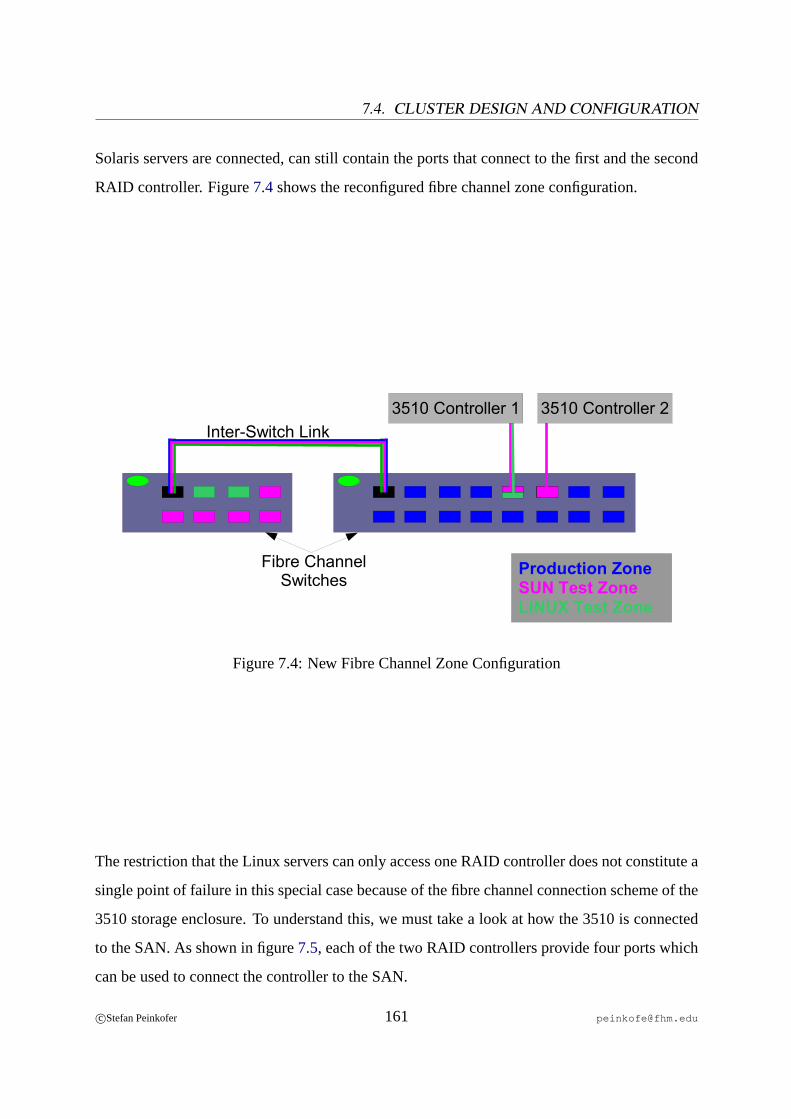
7.4. CLUSTER DESIGN AND CONFIGURATION
Solaris servers are connected, can still contain the ports that connect to the first and the second
RAID controller. Figure7.4shows the reconfigured fibre channel zone configuration.
Production ZoneSUN Test ZoneLINUX Test Zone
3510 Controller 1 3510 Controller 2
Fibre ChannelSwitches
Inter-Switch Link
Figure 7.4: New Fibre Channel Zone Configuration
The restriction that the Linux servers can only access one RAID controller does not constitute a
single point of failure in this special case because of the fibre channel connection scheme of the
3510 storage enclosure. To understand this, we must take a look at how the 3510 is connected
to the SAN. As shown in figure7.5, each of the two RAID controllers provide four ports which
can be used to connect the controller to the SAN.
c©Stefan Peinkofer 161 [email protected]
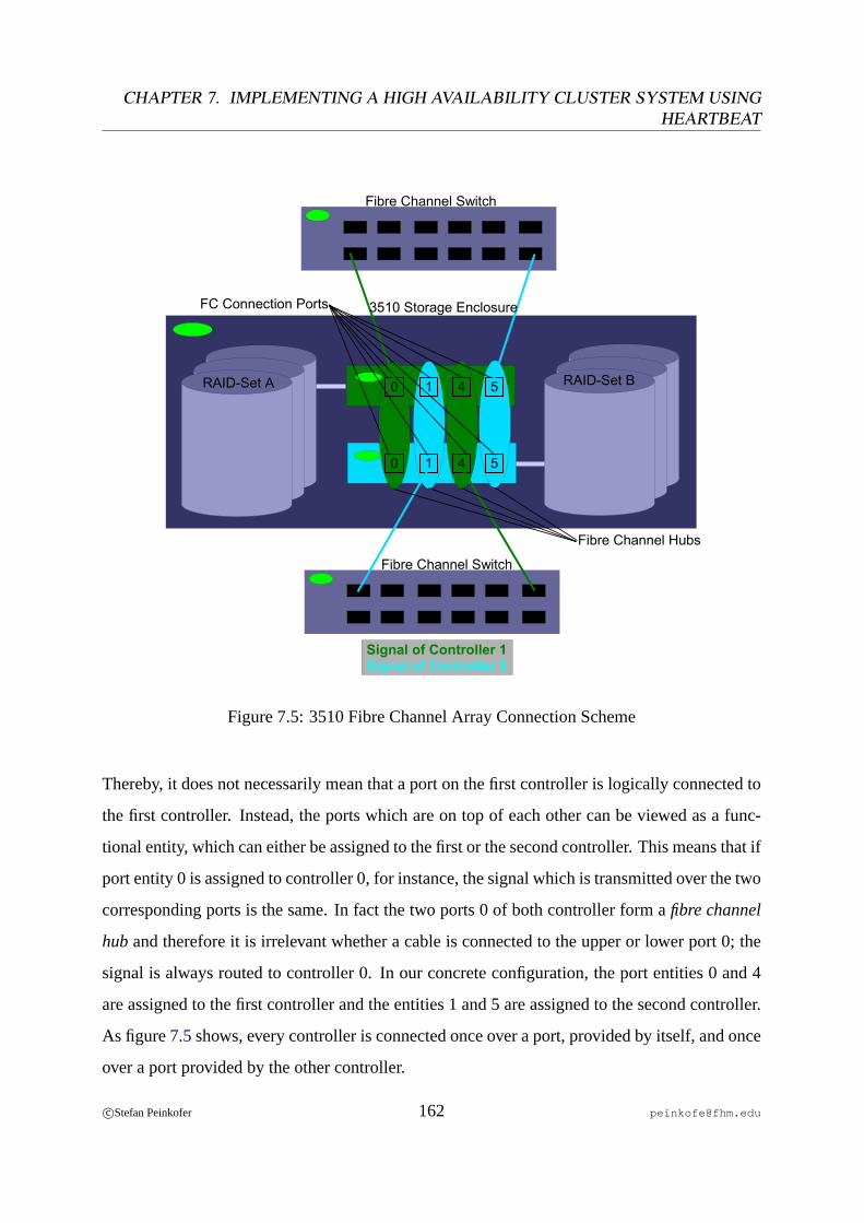
CHAPTER 7. IMPLEMENTING A HIGH AVAILABILITY CLUSTER SYSTEM USINGHEARTBEAT
RAID-Set A RAID-Set B10 4 5
10 4 5
Fibre Channel Switch
Fibre Channel Switch
Signal of Controller 1Signal of Controller 2
FC Connection Ports
Fibre Channel Hubs
3510 Storage Enclosure
Figure 7.5: 3510 Fibre Channel Array Connection Scheme
Thereby, it does not necessarily mean that a port on the first controller is logically connected to
the first controller. Instead, the ports which are on top of each other can be viewed as a func-
tional entity, which can either be assigned to the first or the second controller. This means that if
port entity 0 is assigned to controller 0, for instance, the signal which is transmitted over the two
corresponding ports is the same. In fact the two ports 0 of both controller form afibre channel
huband therefore it is irrelevant whether a cable is connected to the upper or lower port 0; the
signal is always routed to controller 0. In our concrete configuration, the port entities 0 and 4
are assigned to the first controller and the entities 1 and 5 are assigned to the second controller.
As figure7.5shows, every controller is connected once over a port, provided by itself, and once
over a port provided by the other controller.
c©Stefan Peinkofer 162 [email protected]

7.4. CLUSTER DESIGN AND CONFIGURATION
What will happen in case of a controller failure is shown in figure7.6. The ports of the failed
controller will become unusable and the work will be failed over to the second controller. So
even if a zone contains only the first controller, the two switch ports are connected to both
controllers and, therefore, this special zone configuration can survive a controller failure.
RAID-Set ARAID-Set A RAID-Set B10 4 5
0 4 5
Fibre Channel Switch
Fibre Channel Switch
FC Connection Ports
Fibre Channel Hubs
3510 Storage Enclosure
Signal of Controller 1Signal of Controller 2No Signal
RAID-Set A RAID-Set B
1
Figure 7.6: 3510 Fibre Channel Array Failure
7.4.2.4 IP Multipathing
Like on a Sun Cluster, a node in a Heartbeat cluster is typically connected to two different types
of networks, the cluster interconnect network and one or more public networks. To provide a
c©Stefan Peinkofer 163 [email protected]
CHAPTER 7. IMPLEMENTING A HIGH AVAILABILITY CLUSTER SYSTEM USINGHEARTBEAT
local network interface IP fail overfunctionality either for the public network or the cluster
interconnect network interfaces, a special virtual network interface driver calledbonding driver
has to be used. This driver is part of the official Linux kernel. Using this special interface driver
for the cluster interconnect network interfaces is only required if applications running on the
cluster should be able to communicate with each other over the cluster interconnect interfaces.
Heartbeat itself does not require that this driver be used for local interface IP address fail over on
the cluster interconnect interfaces because is can also utilize the various IP addresses, assigned
to the cluster interconnect interfaces, in parallel to sending an receiving heartbeat messages.
To configure and activate the bonding driver, first of all the appropriate kernel module has to
be loaded whereby some driver parameters have to be set. The interesting parameters for a fail
over configuration of the bonding driver are the following:
• mode - This specifies the operation mode of the bonding module. Besides the desired
active/passivefail over mode, several other modes which distribute the load among the
interfaces are available.3
• miimon - This specifies the time interval in milliseconds in which the bonding driver
will evaluate the link status of the physical network interfaces to determine whether the
interface has a link to the network or not. Usually a value of 100 milliseconds is sufficient.
• downdelay - This defines the time delay in milliseconds after which the IP address will
be failed over when the bonding driver encounters a link failure on the active interface.
The value should be set to at least twice themiimon interval to prevent false alarms.
• updelay - This defines the time delay in milliseconds after which the IP address will
be failed back, when the bonding driver encounters that the link on the primary interface
was restored.
By loading the bonding driver, one virtual network device will be created. If multiple bonding
devices are needed, for example for the public network and the cluster interconnect, either a
3The bonding driver was originally developed for the Beowulf high performance computing cluster.
c©Stefan Peinkofer 164 [email protected]
7.4. CLUSTER DESIGN AND CONFIGURATION
special parameter has to be specified when loading the driver which defines how much bonding
interfaces should be created or the driver has to be loaded multiple times. The second method
provides the advantage that the additional bonding interface can be assigned a different config-
uration, whereas the first method will create all bonding interfaces with the same configuration.
The bonding driver also provides aprobe basedfailure detection. In contrast to IPMP on Solaris,
this method does not send and receive ICMP echo requests and replies but sends and receives
ARP requests and replies to/from specified IP addresses. Unfortunately either thelink basedor
theprobe basedfailure detection can be used by the bonding driver. For our cluster system, it
was chosen to use the link based failure detection, because a probe based failure detection could
be easily refitted by implementing a user space program which pings a set of IP addresses and
initiates a manual interface fail over when no ICMP echo reply is received anymore.
After the bonding driver is loaded, the newly created virtual network interface appears as a
normal network device on the system and therefore IP addresses are able to be assigned to it in
the usual ways. Before the IP addresses, configured on the virtual interface, can be used, the
two physical network interfaces, between which the IP addresses will be failed over, have to
be assigned to the virtual network interface. This is done by calling a special command which
takes the name of the desired virtual network interface and the names of the active and passive
physical network interfaces as arguments.
To make this configuration persistent across reboots, the system documentation of the deployed
Linux distribution has to be consulted, because the method for doing so differs from distribution
to distribution.
7.4.2.5 Dependencies to External Provided Services
The operating system depends on the DNS service which is provided by an external host. Since
the DNS service is not highly available yet, this service constitutes a single point of failure.
Fortunately, access to the databases on the cluster nodes is restricted to four hosts. So in order
c©Stefan Peinkofer 165 [email protected]
CHAPTER 7. IMPLEMENTING A HIGH AVAILABILITY CLUSTER SYSTEM USINGHEARTBEAT
to work around this single point of failure, the hostname to IP address mappings of these hosts
are stored in the local/etc/hosts file of the cluster nodes, which will be used in addition to
DNS to perform hostname to IP and IP to hostname resolutions.
7.4.2.6 Time Synchronization
To synchronize the time between the cluster nodes, the NTP configuration from the Sun Clus-
ter was copied and adapted to the Heartbeat cluster environment. Since our Heartbeat cluster
possesses only one Ethernet cluster interconnect, synchronizing the time between the cluster
nodes over this single path constitutes a single point of failure. However it is doubtful that the
redundant path over the public network is more reliable than the cluster interconnect path, since
the path over the network involves more components which could fail. The optimal solution
would be to use the cluster interconnect path as well as the public network path for sending
and receiving NTP messages. This means that the NTP daemon has to send and receive NTP
messages to/from a single node over two dedicated IP addresses, whereby the NTP daemons
will treat every IP address as a dedicated node. From the available documentation it could not
be determined if such a configuration is supported, so another solution was deployed.
On our cluster system, it was chosen to synchronize the time between the nodes only over
the single cluster interconnect path. In addition to that, each cluster node synchronizes to three
different NTP servers over the public network connection. So in case the Ethernet cluster in-
terconnect path fails, the time on the cluster nodes stays synchronized because all nodes are
still synchronized to the time servers. So this configuration tolerates asingle path failureand
therefore is suitable to be deployed on the cluster.
7.4.3 Shared Disks
For the example Heartbeat cluster, two shared disks to store the database files are needed. Be-
cause of the current size of the databases, which are 7.3 GB for the Identity Management System
database and 1.1 GB for the telephone directory database, a 50 GB shared disk and a 10 GB
c©Stefan Peinkofer 166 [email protected]

7.4. CLUSTER DESIGN AND CONFIGURATION
shared disk were chosen, respectively. This space should be sufficient for the planned utilization
time of the databases.
To prevent the cluster nodes of the Sun Cluster system from putting SCSI reservations on these
two disks, access to the two disk is restricted to the two Linux nodes by the LUN masking
feature of the 3510 storage array.
Although it would be desirable to mirror the shared disks across two 3510 enclosures in the
production environment it was chosen to set this aside because although it is possible to create a
software mirror configuration between two shared disks by using the MD driver, the Heartbeat
developers highly recommended not using the MD driver for mirroring shared disks. This is
because the MD driver was not built with shared disks in mind. The work around to fail over
a MD mirrored shared disk is to remove the RAID set on the server which currently maintains
the RAID set and then to create the RAID set on the second server again. According to some
postings on the Heartbeat mailing list, this procedure is error prone and every time the RAID
set is failed over the mirror has to be resynced. So in order to mirror shared disk by software on
a Linux system, commercial products have to be used, which is not intended by the ZaK.
7.4.4 Cluster Software
In the following sections we will look at the initial setup of the Heartbeat environment.
7.4.4.1 Installation of Heartbeat
The Heartbeat program suite is available as precompiled installation packages for various Linux
distributions as well as plain program sources. Since no installation package is available for Red
Hat Enterprise Linux 4, it was chosen to manually compile the Heartbeat program suite. Before
the Heartbeat program can be compiled, it is mandatory to create a user namedhaclient ,
which is a member of the grouphacluster on all cluster nodes. If this is not done before
Heartbeat is compiled, the program suite will not work because of erroneous file permissions.
c©Stefan Peinkofer 167 [email protected]
CHAPTER 7. IMPLEMENTING A HIGH AVAILABILITY CLUSTER SYSTEM USINGHEARTBEAT
To compile Heartbeat, the usualconfigure; make; make install procedure has to
be carried out, as with any other Linux program which is compiled from source.
After the Heartbeat program suite is installed, the kernelwatchdoghas to be enabled, which
is done by loading the appropriate kernel module. The watchdog module will automatically
reboot a node when it is not continuously queried by an application. This can be understood
as local heartbeat; when Heartbeat does not contact the watchdog for a specific time interval,
the watchdog will consider the system failed and reboots it. It is important to set a special
module option when loading the watchdog module, which defines that the watchdog timer,
once enabled, can be disabled again by the software, since otherwise a manual shutdown of the
Heartbeat program would cause the system to reboot.
7.4.4.2 Configuration of Heartbeat
After Heartbeat is installed and the watchdog module is loaded, the initial Heartbeat configura-
tion can be created. This is done by creating the two filesha.cf andauthkeys . Theha.cf
contains the main configuration of Heartbeat. In the following section, we will look at the most
important configuration options of theha.cf :
• node - Defines the name of a cluster node. The name specified here must exactly match
the output of thehostname command. For our configuration, onename entry for
sarek and one forspock has to be specified.
• bcast - This defines the name of a network interface, which Heartbeat will use tobroad-
castheartbeat packages to the other nodes. In our case, one entry for the dedicated cluster
interconnect interfaceeth3 and one for the public network interfacebond0 is used. Al-
though Heartbeat can useunicastsandmulticastsfor exchanging heartbeat messages over
Ethernet, it is highly recommended to use thebroadcast mode, since it is the least error
prone way to exchange messages over an Ethernet network.
• udpport - This defines the UDP port to which heartbeat packages are sent. This param-
eter must only be specified if more than one Heartbeat cluster share a common network
c©Stefan Peinkofer 168 [email protected]
7.4. CLUSTER DESIGN AND CONFIGURATION
for exchanging heartbeat packages, since the packages are not sent directly to the appro-
priate cluster nodes, but broadcast to the whole network. Therefore, each cluster must
use a unique UDP port so that the packages are received only by the appropriate cluster
nodes.
• serial - This defines the name of a serial interface, which Heartbeat will use to ex-
change heartbeat messages to another node. In our case, one entry for the serial device
/dev/ttyS1 is specified.
• baud - This defines the data rate which will be used on the serial interface(s) to exchange
heartbeat messages.
• keepalive - This defines the time interval in seconds in which a node will send heart-
beat messages.
• warntime - This defines the time span in seconds after which a warning message will be
logged, when Heartbeat detects that a node is not sending heartbeat messages anymore.
• deadtime - This defines the time span in seconds after which Heartbeat will declare
a node dead, when Heartbeat detects that the node is not sending heartbeat messages
anymore.
• initdead - When the Heartbeat program is started, it will wait this time span until it
declares the cluster nodes, from which no heartbeat messages were received yet, dead.
• auto_failback - This defines whether resource groups should be automatically failed
back or not.
• watchdog - This defines the path to the device file of the watchdog.
• use_logd - This defines whether Heartbeat will use the system’ssyslog daemonor a
custom log daemonto write log messages. The advantage of the custom log daemon is
that the log messages are writtenasynchronously, which means that the Heartbeat pro-
cesses do not have to wait until the log message is written to the file, but can continue right
c©Stefan Peinkofer 169 [email protected]
CHAPTER 7. IMPLEMENTING A HIGH AVAILABILITY CLUSTER SYSTEM USINGHEARTBEAT
after the log messages are delivered to the log daemon. This increases the performance
of Heartbeat.
• crm - This defines whether Heartbeat should run inHeartbeat v2mode which uses the
newClusterResourceManager(CRM) to manage the resources or if it should run in the
Heartbeat v1 compatibility mode.
The authkeys configuration file defines a password and a hash algorithm, with which the
heartbeat messages are signed. The following hash algorithms can be specified:
• CRC- Use theCyclic RedundantCodehash algorithm
• MD5- Use theMD5 hash algorithm
• SHA1- Use theSHA1hash algorithm
The CRC method should only be used if all paths used as cluster interconnect are physically
secure networks, since it provides no security but only prevents against packet corruption.
After Heartbeat is configured, it has to be tested whether the specified cluster interconnect paths
work. Therefore, Heartbeat provides a special command which will test whether the specified
paths can be used as cluster interconnect paths. The most common failure scenarios, which
disable Heartbeat from sending heartbeat messages are bad firewall rules on Ethernet interfaces
and faulty cabling between serial interfaces.
7.4.4.3 File System for the Database Files
Since PostgreSQL cannot benefit from a shared file system and Heartbeat itself does not pro-
vide a shared file system, the deployed file system on the shared disk is a usual Linuxext3file
system. Although Linux in general supports many file systems and some of them provide a
better performance than theext3file system,ext3has to be used, since it is the only file system
which is supported by Red Hat Enterprise Linux 4.
c©Stefan Peinkofer 170 [email protected]
7.4. CLUSTER DESIGN AND CONFIGURATION
After the two file systems have been created on the shared disks, an appropriate mount point
has to be created for each shared disk. In contrast to Solaris, the “disk partitionto mount point“
mapping has to be specified in the/etc/fstab file but the Heartbeat developers recommend
that it should not be specified in this file, to avoid the file system being accidentally mounted
manually.
7.4.5 Applications
The only application which will be made highly available on the cluster system is the Post-
greSQL database software. Although PostgreSQL was already installed together with the oper-
ating system, it was chosen to use a self compiled version of PostgreSQL because the version
delivered along with the operating system is 7.x and theup-to-dateversion is 8.x. The de-
cision for PostgreSQL version 8.x is mainly founded on the fact that version 8.x provides a
point-in-time recoverymechanism. With point-in-time recovery it is possible to restore the
database state the database had at a specific point in time. This is useful for example when
the database is logically corrupted by a database command, like an accidental deletion of data
records. Without point-in-time recovery, the backup of the database has to be restored, which
may be taken hours before the actual database corruption. So all database changes made since
the last database backup are lost. With point-in-time recovery, only the changes which were
made after the database corruption are lost since the database can berolled backto the point in
time right before the execution of the hazardous command.
It was chosen to store the PostgreSQL application binaries on the local disks of the cluster
nodes, since noshared file systemis used and therefore two instances of the application binaries
have to be maintained anyway. Therefore storing the application binaries on the shared disks
would provide no benefit.
Before PostgreSQL can be compiled, a user calledpostgres , which is member of the group
postgres has to be created. After that, the compilation and installation of PostgreSQL is
done like with any other software which has to be compiled from source.
c©Stefan Peinkofer 171 [email protected]
CHAPTER 7. IMPLEMENTING A HIGH AVAILABILITY CLUSTER SYSTEM USINGHEARTBEAT
After PostgreSQL is installed, the databases instance files on the shared disks have to be created.
In the first step, the shared disks have to be mounted on the appropriate mount points. After
that, a directory calleddata has to be created on both shared disks. It must be ensured that the
mount points and the data directories are owned by thepostgres user and thepostgres
group and that user and group have full access to them. After that, the database instance files
have to be created within bothdata directories, by calling a special PostgreSQL command.
After the database instance files are created, the database instances have to be configured. This
is done by adopting thepostgresql.conf file which has been automatically created along
with the database instance files within thedata directory. To use PostgreSQL on the cluster,
the following configuration parameters have to be changed:
• listen_addresses - The value of this parameter has to be set to the IP address which
is assigned to the specific database instance. If the database should not listen to any IP
address, this value must be empty, since PostgreSQL will bind to the localhost IP address
by default. Therefore when both PostgreSQL would run on the same node, one instance
would fail to bind to the localhost IP address, since the other instance is already bound to
the IP on the same TCP port.
• unix_socket_directory - This is the directory in which the PostgreSQL instance
will create its UNIX domain socket file, which will be used by local clients to contact
the database. Since the default value for this parameter is/tmp and the socket directory
cannot be shared by PostgreSQL instances, it has to be set to a different directory for
each PostgreSQL instance. On our cluster it was chosen to use the directory to which the
shared disk of the specific PostgreSQL instance is mounted.
Finally, both PostgreSQL instances must be configured to accept connections of thepostgres
user from all IP addresses which are bound to the public network interfaces of the cluster nodes.
This is needed because the health check function of the PostgreSQL resource agent does not
specify a password when connecting to the database instance.
c©Stefan Peinkofer 172 [email protected]

7.4. CLUSTER DESIGN AND CONFIGURATION
7.4.6 Configuring the STONITH Devices
In this section we will discuss how theSTONITH deviceshave to be configured so that Heart-
beat is able to determine which STONITH devices can be used to STONITH a particular node.
Heartbeat treats a STONITH device like a normal cluster resource. Depending on whether
only one or multiple nodes can access the STONITH device simultaneously, aSTONITH re-
sourcecan be active only on one or on multiple nodes at a time. Depending on the deployed
STONITH device, the hostnames of the cluster nodes which can be “STONITHed“ by a partic-
ular STONITH resource are either configured as acustom resource propertyof the STONITH
resource or directly on the STONITH device. The STONITH devices for which Heartbeat re-
quires that the hostnames are configured on the STONITH device usually provide a way to let
the administrator assign names to the various outlet plugs. To define that a cluster node can be
“STONITHed“ by such a device, all outlet plugs which are connected to the particular host must
be assigned the hostname of the particular cluster node. When Heartbeat starts the resource of
such a STONITH device, it will query the particular hostnames directly from the STONITH
device.
It is worth mentioning how Heartbeat carries out a STONITH operation. In every cluster parti-
tion, a so-calledDesignatedCoordinator (DC) exists, which is among other things responsible
for initiating STONITH operations. If the DC decides to STONITH a node it broadcasts a re-
quest containing the name of the node to STONITH, to all cluster members, including itself.
Every node which receives the request will look if it currently runs a STONITH resource which
is able to STONITH the particular node and if so will carry out the STONITH operation and
announce whether the STONITH operation failed or succeeded to the other cluster members.
7.4.7 Creating the Heartbeat Resource Configuration
Since the configuration of resources and resource groups for Heartbeat is not as easy and well
documented as for Sun Cluster, we will look in the following sections with a little more detail
on how exactly the resources and resource groups are defined.
c©Stefan Peinkofer 173 [email protected]

CHAPTER 7. IMPLEMENTING A HIGH AVAILABILITY CLUSTER SYSTEM USINGHEARTBEAT
7.4.7.1 Resources and Resource Dependencies
Based on the requirements, the cluster should provide two highly available PostgreSQL database
instances, whereby each node should run one instance by default. Therefore each database in-
stance requires a dedicated IP address and that the shared disk which contains the database files
of the instance is mounted. It was chosen to deploy additionally two other resource types which
are used to inform the administrators in case of a failure.
Since Heartbeat requires that a node must be able to fence itself but in our case every node
is only connected to the STONITH device which allows to fence the other node, in addition to
the two STONITH resources for thephysical STONITH devices, two STONITH resources for
software STONITH deviceshave to be deployed. To STONITH a node, the software STONITH
devices will initiate a quick and ungraceful reboot of the node.
Figure 7.7 shows the needed resources and resource dependencies whereby two specialities
exists:
1. The STONITH resources are not configured within a resource group. This is done because
Heartbeat does not necessarily require that a resource is contained in a resource group and
since all STONITH resources are independent of each other the overhead of defining four
additional resource groups can be saved.
2. The IP address, shared disk and application resources do not really depend on the two
resources which are used to notify the administrators but since the failure of the resource
group which contains the database instance is from interest for the administrators, the two
resources have to be contained in the same resource group as the database application
instance.
c©Stefan Peinkofer 174 [email protected]

7.4. CLUSTER DESIGN AND CONFIGURATION
infobase_mailalarmType: MailTo
infobase_audioalarmType: AudibleAlarm
infobase_ipType: IPAddr
infobase_dataType: Filesystem
infobase_postmasterType: Postgres
kill_sarekType: wti_nps
suicide_spockType: suicide
telebase_mailalarmType: MailTo
telebase_audioalarmType: AudibleAlarm
telebase_ipType: IPAddr
telebase_dataType: Filesystem
telebase_postmasterType: Postgres
kill_spockType: wti_nps
suicide_sarekType: suicide
infobase_rg telebase_rg
Resource X depends on that Resource Y runs on the same host
Resource X has a pseudo dependency to Resource Y
ResourceResource GroupSTONITH Resource
Figure 7.7: Resources and Resource Dependencies on the Heartbeat Cluster
A special constraint on the STONITH resources is that the resources for the physical STONITH
devices are only allowed to run on the node which is connected by the Ethernet connection to
the corresponding STONITH device whereas the resources of the software STONITH devices
are only allowed to run on the node which should be fenced by the resource. Figure7.8shows
the valid location configuration of the STONITH resources and figure7.9shows the invalid one.
c©Stefan Peinkofer 175 [email protected]
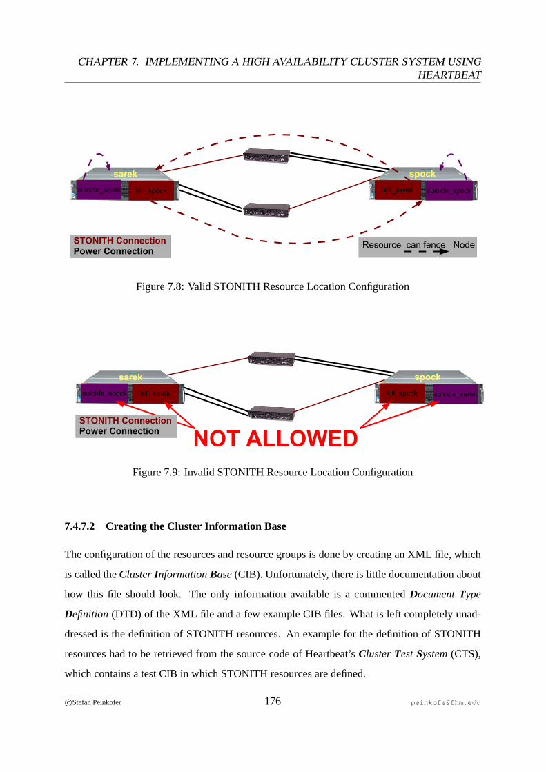
CHAPTER 7. IMPLEMENTING A HIGH AVAILABILITY CLUSTER SYSTEM USINGHEARTBEAT
STONITH ConnectionPower Connection
kill_spock suicide_spock
sarek spockkill_sareksuicide_sarek
Resource can fence Node
Figure 7.8: Valid STONITH Resource Location Configuration
kill_spocksuicide_spock
sarek spock
kill_sarek suicide_sarek
NOT ALLOWEDSTONITH ConnectionPower Connection
Figure 7.9: Invalid STONITH Resource Location Configuration
7.4.7.2 Creating the Cluster Information Base
The configuration of the resources and resource groups is done by creating an XML file, which
is called theClusterInformationBase(CIB). Unfortunately, there is little documentation about
how this file should look. The only information available is a commentedDocumentType
Definition (DTD) of the XML file and a few example CIB files. What is left completely unad-
dressed is the definition of STONITH resources. An example for the definition of STONITH
resources had to be retrieved from the source code of Heartbeat’sClusterTestSystem(CTS),
which contains a test CIB in which STONITH resources are defined.
c©Stefan Peinkofer 176 [email protected]
7.4. CLUSTER DESIGN AND CONFIGURATION
In contrast to Sun Cluster, the definition of resources and resource groups is very complex
since Heartbeat requires in addition to the usual resource group and resource information also
information about what the Cluster Resource Manager should do with the resource group or
resource when certain events occur. Since the discussion of all possible configuration options
the CIB provides, would go beyond the scope of this thesis we will limit the discussion to a
logical description of the CIB, which was created for our cluster system. However, the example
CIB file is contained on the CD-ROM, delivered along with this document.
The Cluster Information Base is divided into three sections. Section one contains the basic
configuration of the Cluster Resource Manager, which is responsible for all resource related
tasks, like starting, stopping and monitoring the resources. Section two contains the actual con-
figuration of the resource groups and resources. Section three contains constraints which could
define for example on which node a resource should run by default or could define resource
dependencies between resources, contained in different resource groups.
In the Cluster Resource Manager configuration segment, the following information was pro-
vided:
• A cluster transition, like a fail over, has to be completed within 120 seconds. If the
transition takes longer, it is considered failed and a new transition has to be initiated.
• By default every resource can run on every cluster node.
• The Cluster Resource Manager should enable fencing of failed nodes.
For the resource groups, the following information was specified:
• The corresponding name of the resource group.
• When the Resource Group should be failed over because of a node failure, the Resource
Manager must not start the resources of the resource group, until the failed node can be
successfully fenced.
c©Stefan Peinkofer 177 [email protected]
CHAPTER 7. IMPLEMENTING A HIGH AVAILABILITY CLUSTER SYSTEM USINGHEARTBEAT
Heartbeat implicitly assumes that the order in which the resources within a resource group are
defined reflects the resource dependencies of the resources within this group. This means that
Heartbeat will start the resource group by starting the resources within the group in a top-down
order and it will stop them in the reverse order. So the resources within the resource groups are
specified in the following order:
• AudibleAlarm
• MailTo
• IPaddr
• Filesystem
• Postgres
To configure a resource, the following information has to be provided:
• The name of the resource.
• The class of the cluster agent which should be used for the resource. ForHeartbeat v2
resource agents, which provide a monitoring callback function, the class has to be set to
ocf (OpenClusterFramework).
• The name of the resource agent to use.
• The name of the vendor who implemented the resource agent. Heartbeat v2 defines that
OCF resource agents, which are implemented by different vendors, can have the same
name. This option is used to distinguish between them.
• The timeout of theStart callback function, after which a not yet completedStart opera-
tion is considered failed.
• The timeout of theStopcallback function, after which a not yet completedStopoperation
is considered failed.
c©Stefan Peinkofer 178 [email protected]

7.4. CLUSTER DESIGN AND CONFIGURATION
• The timeout of theMonitor callback function, after which a not yet completedMonitor
operation is considered failed.
• The time interval in which theMonitor function should be executed.
• The custom resource properties of the specific resource type. The concrete custom re-
source properties, specified for the deployed resource types are:
– AudibleAlarm
∗ The hostname of the cluster node on which the resource group should run by
default.
– MailTo
∗ The E-mail addresses of the administrators who should be notified.
– IPaddr
∗ The IP address of thelogical hostname, which should be maintained by this
resource. Like on Sun Cluster, the network interface to which the IP address
should be assigned need not be specified because the resource agent will auto-
matically assign it to the appropriate network interface.
– Filesystem
∗ The device name of the disk partition, which should be mounted.
∗ The directory to which the disk partition should be mounted.
∗ The file system type which is used on the disk partition.
– Postgres
∗ The directory to which the PostgreSQL application was installed.
∗ The directory which contains the database and configuration file of the Post-
greSQL instance.
∗ The absolute path to a file, to which all messages which are written by the
PostgreSQL process tostdout andstderr , are redirected.
c©Stefan Peinkofer 179 [email protected]
CHAPTER 7. IMPLEMENTING A HIGH AVAILABILITY CLUSTER SYSTEM USINGHEARTBEAT
∗ The hostname of the IP address to which the PostgreSQL instance is bound.
The order in which the resources are defined within the resource group causes one negative side
effect. The failure of aStart of Stopcallback function of theAudibleAlarmor MailTo resource
would cause the Cluster Resource Manager cancel to start or stop the resource group and fail it
over to another node. Since the two resources are only used to notify the administrator about a
fail over, the failure of such a resource does not justify that the start or stop of a resource group
is cancelled on a node and therefore may remain inactive until a human intervention occurs. To
get around this problem the Cluster Resource Manager was configured to ignore the failure of
a callback function, provided by these resources so in case a function of these resources fails,
the Cluster Resource Manager will pretend that it didn’t fail. Additionally the Cluster Resource
Manager was configured not to perform any monitoring operation on the two resources.
For the other resources within the group, the following behavior was configured: If theStart or
Monitor callback functions fail or time out, the resource group should be failed over to another
node. If theStop callback function fails or times out, the node on which the resource group is
currently hosted should be fenced. This is needed, in order to fail over the resource group in this
case, since the failure of a stop operation indicates that the resource is still running. The fencing
of the node, on which the failure of the stop operation occurred, will implicitly stop the resource
and therefore another node can take over the resources after the node is fenced successfully.
As already said, the STONITH resources were defined without being assigned to a specific
resource group. To configure a STONITH resource, the following information has to be pro-
vided:
• The STONITH resource can be started without any prerequisites, like a successful fencing
of a failed node.
• When any callback function of the STONITH resources fails, the corresponding
STONITH resource should be restarted. Since the STONITH resources cannot be failed
over in our configuration, this is the only sensible option.
c©Stefan Peinkofer 180 [email protected]
7.4. CLUSTER DESIGN AND CONFIGURATION
• The name of the STONITH resource.
• The class of the STONITH resource agent, which isstonith .
• The name of the deployed STONITH device type.
• The timeout of theStart callback function.
• The timeout of theStopcallback function.
• The timeout of theMonitor callback function.
• The time interval in which theMonitor function should be performed.
• The custom resource properties of the specific STONITH resource type. The concrete
custom resource properties, specified for the deployed STONITH resource types are:
– wti_nps (Physical STONITH device)
∗ The IP address of the STONITH device.
∗ The password which has to be specified in order to log in to the STONITH
device.
– suicide (Software STONITH device)
∗ No custom resource property is needed, since the suicide resource will query
the name of the node which can be “STONITHed“ by calling thehostname
command.
In the third section, the following constraints were defined:
• The resource group of the Identity Management System database,infobase_rg should
run onspock by default.
• The resource group of the telephone directory databasetelebase_rg should run on
sarek by default.
c©Stefan Peinkofer 181 [email protected]
CHAPTER 7. IMPLEMENTING A HIGH AVAILABILITY CLUSTER SYSTEM USINGHEARTBEAT
• The STONITH resourcekill_sarek , which can be used byspock to fencesarek ,
can only run onspock .
• The STONITH resourcesuicide_spock , which can be used byspock to fence itself,
can only run onspock .
• The STONITH resourcekill_spock , which can be used bysarek to fencespock ,
can only run onsarek .
• The STONITH resourcesuicide_sarek , which can be used bysarek to fence itself,
can only run onsarek .
7.5 Development of a Cluster Agent for PostgreSQL
In the following section we will look at the development of a cluster agent for the PostgreSQL
application. ForHeartbeat v2 resource agents, Heartbeat provides a small library, implemented
as a shell script, which currently provides some functions forlogginganddebuggingand defines
somereturn valuesand file system paths to various important Heartbeat directories. Before we
can discuss the implementation of the PostgreSQL agent, we must first look at the interaction
model between Heartbeat and the cluster agent.
7.5.1 Heartbeat Resource Agent Callback Model
Like Sun Cluster, Heartbeat provides a fixed set of callback functions, which will be called
by the cluster software under well defined circumstances. In contrast to Sun Cluster, Heart-
beat provides the ability to define further callback functions. Since the only way to call these
functions is to define that Heartbeat should call them in regular time intervals, the use, these
additional callback functions provide, is limited. One possible use case would be to implement
an additional monitor function that performs a more comprehensivehealth checking procedure
which uses more computing resources and therefore should not be called so often as the basic
monitoring function. For the predefined callback methods Heartbeat also defines the task of
c©Stefan Peinkofer 182 [email protected]

7.5. DEVELOPMENT OF A CLUSTER AGENT FOR POSTGRESQL
this callback method and the expected return values. To implement a Heartbeat cluster agent,
one executable function which contains all callback functions has to be developed. To call a
specific callback function, Heartbeat will pass themethod nameas command line argument to
the cluster agent. In fact, Heartbeat does not require that a cluster agent is written in a specific
programming language, but typically the cluster agents are implemented as shell scripts.
In the following we will look briefly at the predefined callback methods:
• Start - This method is called when Heartbeat wants to start the resource. The function
must implement the necessary steps to start the application and it must only return suc-
cessfully if the application was started.
• Stop - This method is called when Heartbeat wants to stop a resource. The function must
implement the necessary steps to stop the application and it must only return successfully
if the application was stopped.
• Status- The Heartbeat documentation does not describe under which circumstances this
callback method is called; it just states that it is called in many places. The purpose of the
status callback method is to determine whether the application processes of the specific
resource instance are running or not.
• Monitor - This method is called by Heartbeat in a regular, definable time interval to
verify the health of the resource. It only must return successfully if the specific resource
instance is considered healthy, based on the performed health check procedure.
• Meta-data - The Heartbeat documentation does not describe under which circumstances
this callback method is called. It must return a description of the cluster agent in XML
format. The description contains the definition of theresource agent propertiesand the
definition of the implemented callback functions. The description this function returns
is comparable to theresource type propertiesandcustom resource propertieswhich are
contained in the resource type registration file of a Sun Cluster agent.
c©Stefan Peinkofer 183 [email protected]

CHAPTER 7. IMPLEMENTING A HIGH AVAILABILITY CLUSTER SYSTEM USINGHEARTBEAT
Heartbeat requires that a cluster agent implements at least theStart, Stop, StatusandMeta-data
callback methods.
7.5.2 Heartbeat Resource Monitoring
As we saw in the previous chapter, Heartbeat defines a direct callback function for the resource
monitoring task. In contrast to Sun Cluster, Heartbeat requires the resource agent just to return
the health statusof the resource instance and the appropriate actions for a failed resource are
determined and carried out by Heartbeat itself.
7.5.3 Heartbeat Resource Agent Properties
Like Sun Cluster, Heartbeat defines a set ofresource type propertiesand resource properties
which are used to define the configuration of a cluster agent. As already discussed, additional
custom resource propertiescan be specified, too. In contrast to Sun Cluster, which provides a
common file for all properties, the resource type properties and custom resource properties are
specified within the cluster agent and passed to Heartbeat by theMeta-data function and the
resource properties are specified directly in thecluster information base.
7.5.3.1 Resource Type Properties
In the following section, we will look at the resource type properties of a Heartbeat cluster agent
and their corresponding attributes:
• resource-agent - This property specifies general information about the cluster agent.
It takes the following attributes:
– name - Defines the name of the resource agent type.
– version - Defines the program version of the agent.
• action - This property defines a callback function which the cluster agent provides. It
takes the following attributes:
c©Stefan Peinkofer 184 [email protected]

7.5. DEVELOPMENT OF A CLUSTER AGENT FOR POSTGRESQL
– name - Defines the name of the callback function.
– timeout - Defines the default timeout, after which the cluster will consider the
function failed, if it has not yet returned.
– interval - Defines the default interval in which the function should be called.
This attribute is only necessary for monitoring functions.
– start-delay - Defines the time delay Heartbeat will wait after the execution of
aStart function before it calls the status function.
7.5.3.2 Custom Resource Properties
To define a custom resource property, the special propertyparameter in conjunction with the
propertycontent has to be specified in the XML description which is printed tostdout by
theMeta-data callback function. The propertyparameter takes the following attributes:
• name - The name of the custom resource property.
• unique - Defines whether the value assigned to the custom resource property must be
unique across all configured instances of this cluster agent type or not.
Thecontent property takes the following attributes:
• type - This attribute defines the data type of the custom resource property value. Valid
types are:boolean , integer andstring .
• default - This attribute defines the default value which is assigned to the custom re-
source property.
The values of the custom resource properties can be individually overwritten in the cluster
information base, for each resource of the specific type. The values of these properties as well
as the values of the normal resource properties are passed to the resource agent as environment
variables which are named according the following naming scheme:
$OCF_RESKEY_<property name> .
c©Stefan Peinkofer 185 [email protected]

CHAPTER 7. IMPLEMENTING A HIGH AVAILABILITY CLUSTER SYSTEM USINGHEARTBEAT
7.5.4 Creating the PostgreSQL Resource Agent
A Heartbeat resource agent has to be created from scratch since Heartbeat provides neither an
agent builder similar to Sun Cluster, nor aresource agent template. Since there is sparse doc-
umentation about how to create a resource agent it is a good idea to look at the cluster agents,
which are delivered along with Heartbeat, to determine how a Heartbeat cluster agent should be
programmed. We will look at the development of a Heartbeat cluster agent in a bit more detail
than we did in the Sun Cluster section because there is still so little documentation about it. The
source of the cluster agent can be found on the CD-ROM delivered along with this document.
A special requirement of Heartbeat is that each function a cluster agent provides must be idem-
potent.
7.5.4.1 Possible Return Values
TheOpen Cluster Frameworkdefines a fixed set of return values a cluster agent is allowed to
return. The defined return values are:
• OCF_SUCCESS- Must be returned if a callback function finished successfully.
• OCF_ERR_GENERIC- Must be returned if an error occurred which does not match any
other defined error return code.
• OCF_ERR_ARGS- Must be returned if a custom resource property value is not reason-
able.
• OCF_ERR_UNIMPLEMENTED- Must be returned if the callback function name, speci-
fied by Heartbeat as command line argument, is not implemented by the resource agent.
• OCF_ERR_PERM- Must be returned if a task cannot be carried out because of wrong
user permissions.
• OCF_ERR_INSTALLED- Must be returned if the application or a tool which is used by
the cluster agent is not installed.
c©Stefan Peinkofer 186 [email protected]
7.5. DEVELOPMENT OF A CLUSTER AGENT FOR POSTGRESQL
• OCF_ERR_CONFIGURED- Must be returned if the configuration of the application in-
stance is invalid for some reason.
• OCF_NOT_RUNNING- Must be returned if the application instance is not running.
It is worth mentioning that except for theStatuscallback function, the cluster agent must not
print messages tostdout or stderr since doing so can cause segmentation faults in Heart-
beat under special circumstances. To print messages, the special functionocf_log has to be
used, which is provided by Heartbeats cluster agent library and writes the messages directly to
the appropriate log file.
7.5.4.2 Main Function
The main function of the cluster agent must perform initialization tasks like retrieving thecus-
tom resource property valuesfrom the shell environment. In addition to that, it should validate
whether all external commands used by the resource agent functions are available and whether
the custom resource property values are set reasonably. In the last step, the main function must
call the appropriate callback function, which was specified by Heartbeat as command line argu-
ment.
7.5.4.3 Meta-data Function
The PostgreSQL resource agent defines the following custom resource properties:
• basedir - Defines the absolute path of the base directory, to which PostgreSQL was
installed. This value does not have to be unique, since many resource instances can use
the same application binaries.
• datadir - Defines the absolute path of the directory in which the database and configu-
ration files of the application instance are stored. This value has to be unique since every
instance must use different database and configuration files.
• dbhost - Defines the hostname or IP address on which the specific PostgreSQL instance
is listening.
c©Stefan Peinkofer 187 [email protected]
CHAPTER 7. IMPLEMENTING A HIGH AVAILABILITY CLUSTER SYSTEM USINGHEARTBEAT
• logfile - Defines the absolute path of a file, to which thestdout andstderr output
of the PostgreSQL instance is redirected.
7.5.4.4 Start Function
TheStart function should validate the configuration of the application instance before it tries
to start the application and returnOCF_ERR_CONFIGUREDif the configuration is invalid.
TheStart function of the PostgreSQL resource agent performs the following steps:
• Determine if the directory specified by the custom resource propertydatadir contains
PostgreSQL database and configuration files. If not, returnOCF_ERR_ARGS.
• Determine if the version of the database files matches the deployed PostgreSQL version4.
If not, returnOCF_ERR_CONFIGURED.
• Determine if the specified instance of PostgreSQL is already running. If so, return
OCF_SUCCESSimmediately for idempotency reasons.
• Remove the application state filepostmaster.pid , if it exists. This step is needed
because PostgreSQL will store the key of itsshared memory areain this file. In an
active/activeconfiguration it is very likely that both PostgreSQL instances will use the
same key, since they are running on different nodes. However, if one node dies and the
instance is failed over, PostgreSQL will refuse to start the instance on the other node as a
precaution, because a shared memory segment with the same key it used before already
exists. PostgreSQL suggests the following two options to deal with such a situation:
– Remove the shared memory segment manually, which cannot be done in this special
case because the shared memory segment belongs to another PostgreSQL instance.
– Remove thepostmaster.pid file, which will cause PostgreSQL to create a new
shared memory segment, which then is implicitly assigned a different key.
4The format of the database files can change between major releases.
c©Stefan Peinkofer 188 [email protected]

7.5. DEVELOPMENT OF A CLUSTER AGENT FOR POSTGRESQL
• Call the appropriate command, which starts the PostgreSQL instance.
• Wait five seconds and then determine if the specified instance of PostgreSQL is running.
If so, returnOCF_SUCCESS, if not returnOCF_ERR_GENERIC.
7.5.4.5 Stop Function
TheStop function of the PostgreSQL resource agent performs the following steps:
• Call the appropriate command which stops the PostgreSQL instance. Do not check to
determine whether the call returned successfully or not because of idempotency reasons.
• Determine if the specified application instance is still running. If so return
OCF_ERR_GENERIC, if not returnOCF_SUCCESS.
7.5.4.6 Status Function
TheStatusfunction of the PostgreSQL resource agent performs the following step:
• Determine if a PostgreSQL process exists in the process list, which uses the directory
specified by the custom resource propertydatadir as instance directory. If so print
running to stdout and returnOCF_SUCCESS. If not print stopped to stdout
and returnOCF_NOT_RUNNING.
7.5.4.7 Monitor Function
TheMonitor function of the PostgreSQL resource agent performs the following steps:
• Determine if the specified instance of PostgreSQL is already running. If not, return
OCF_NOT_RUNNING. This is important since it is not guaranteed that the monitoring
function is not called until the start function is called. ReturningOCF_ERR_GENERIC
in this case would indicate to Heartbeat that the resource has failed and Heartbeat would
trigger the appropriate action for a failed resource, like failing over the resource for ex-
ample.
c©Stefan Peinkofer 189 [email protected]

CHAPTER 7. IMPLEMENTING A HIGH AVAILABILITY CLUSTER SYSTEM USINGHEARTBEAT
• Connect to the PostgreSQL server, which listens on the hostname or IP address as speci-
fied by the custom resource propertydbhost . Then call the following SQL commands:
– Remove the test database calledhb_rg_testdb .
– Create the test databasehb_rg_testdb again.
– Create a database table within the test database.
– Insert a data record to the test table.
– Select the inserted data record from the test table.
– Delete the test table.
– Remove the test database.
• If any of the performed SQL commands, except for the first database remove call, failed,
returnOCF_ERR_GENERIC, otherwise returnOCF_SUCCESS.
7.6 Evaluation of Heartbeat 2.0.x
As already discussed in chapter4.3on page73, a “brand new“ software version should not be
deployed in a production environment without performing a comprehensive set oftest cases,
in the first place. The following sections will discuss the testing process which was used to
evaluate the maturity of Heartbeat 2.0.2.
7.6.1 Test Procedure Used
Usually, software is tested by comparing the actual behavior of the software with the expected
behavior described by the software specification. The Heartbeat 2.0.x implementation orients
itself on theOpen Cluster Frameworkspecification. Unfortunately, not the whole OCF specifi-
cation is implemented in Heartbeat 2.0.x yet and the OCF specification does not cover all things
which are implemented in Heartbeat 2.0.x. For Heartbeat 2.0.x itself, no real specifications ex-
ist. The only available information about the desired behavior is the Heartbeat documentation.
Unfortunately, the sparse documentation which is available is not sufficient to derive a complete
c©Stefan Peinkofer 190 [email protected]
7.6. EVALUATION OF HEARTBEAT 2.0.X
specification. In addition to that, the behavior of Heartbeat is mainly swayed by the deployed
configuration. To test Heartbeat 2.0.x under these conditions, it was chosen to create a test pro-
cedure which initiates common cluster events and failure scenarios. The reaction of Heartbeat
to these failure scenarios was then compared to the expected behavior which was derived partly
from the available documentation, partly by comments in the source code and partly by implicit
knowledge of cluster theory.
Although Heartbeat provides an automated test tool calledCluster TestSystem(CTS) it was
chosen to use a manual test procedure. This decision is mainly founded on the following
thoughts:
• The Heartbeat developers could not guarantee that the CTS would work with the con-
figuration, which was created for our cluster system since the CTS cannot deal with all
possible CIB constructs.
• Setting up the CTS test environment would take a lot of time, which would be wasted in
case the CTS really could not deal with the concrete CIB configuration.5
The several steps of the developed test procedure, as well as the expected behavior, are shown
in table7.1.
(Note: With the terms ofstarting andstoppinga resource group, it is meant that the resources
belonging to the resource group are started or stopped and it is implicitly assumed that they are
started or stopped in the right order.)
Since at the time the test steps were developed, Heartbeat provided no function to manually fail
over resource groups yet, theauto_failback option was enabled for the test procedure so
that a resource group is automatically failed back to the default node by the time the node joins
the cluster again. In addition to that, Heartbeat was only started manually and not automatically
at system start.
5The initial timeline for the practice part was already violated because of two unexpected software bugs, found
in the Solaris operating system and the Sun Cluster software.
c©Stefan Peinkofer 191 [email protected]
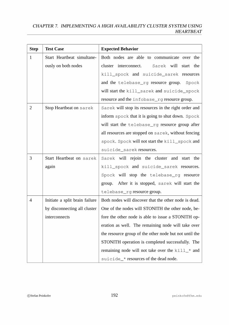
CHAPTER 7. IMPLEMENTING A HIGH AVAILABILITY CLUSTER SYSTEM USINGHEARTBEAT
Step Test Case Expected Behavior
1 Start Heartbeat simultane-
ously on both nodes
Both nodes are able to communicate over the
cluster interconnect. Sarek will start the
kill_spock and suicide_sarek resources
and the telebase_rg resource group. Spock
will start thekill_sarek andsuicide_spock
resource and theinfobase_rg resource group.
2 Stop Heartbeat onsarek Sarek will stop its resources in the right order and
inform spock that it is going to shut down.Spock
will start the telebase_rg resource group after
all resources are stopped onsarek , without fencing
spock . Spock will not start thekill_spock and
suicide_sarek resources.
3 Start Heartbeat onsarek
again
Sarek will rejoin the cluster and start the
kill_spock and suicide_sarek resources.
Spock will stop the telebase_rg resource
group. After it is stopped,sarek will start the
telebase_rg resource group.
4 Initiate a split brain failure
by disconnecting all cluster
interconnects
Both nodes will discover that the other node is dead.
One of the nodes will STONITH the other node, be-
fore the other node is able to issue a STONITH op-
eration as well. The remaining node will take over
the resource group of the other node but not until the
STONITH operation is completed successfully. The
remaining node will not take over thekill_* and
suicide_* resources of the dead node.
c©Stefan Peinkofer 192 [email protected]
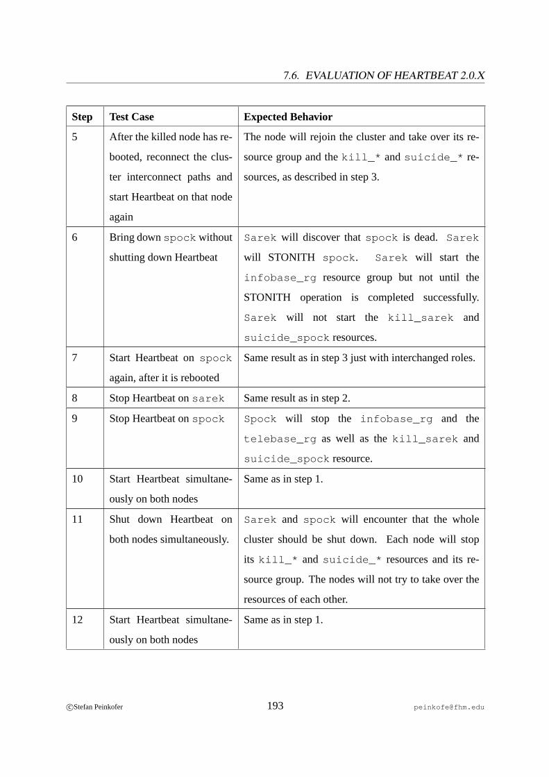
7.6. EVALUATION OF HEARTBEAT 2.0.X
Step Test Case Expected Behavior
5 After the killed node has re-
booted, reconnect the clus-
ter interconnect paths and
start Heartbeat on that node
again
The node will rejoin the cluster and take over its re-
source group and thekill_* andsuicide_* re-
sources, as described in step 3.
6 Bring downspock without
shutting down Heartbeat
Sarek will discover thatspock is dead. Sarek
will STONITH spock . Sarek will start the
infobase_rg resource group but not until the
STONITH operation is completed successfully.
Sarek will not start the kill_sarek and
suicide_spock resources.
7 Start Heartbeat onspock
again, after it is rebooted
Same result as in step 3 just with interchanged roles.
8 Stop Heartbeat onsarek Same result as in step 2.
9 Stop Heartbeat onspock Spock will stop the infobase_rg and the
telebase_rg as well as thekill_sarek and
suicide_spock resource.
10 Start Heartbeat simultane-
ously on both nodes
Same as in step 1.
11 Shut down Heartbeat on
both nodes simultaneously.
Sarek and spock will encounter that the whole
cluster should be shut down. Each node will stop
its kill_* and suicide_* resources and its re-
source group. The nodes will not try to take over the
resources of each other.
12 Start Heartbeat simultane-
ously on both nodes
Same as in step 1.
c©Stefan Peinkofer 193 [email protected]
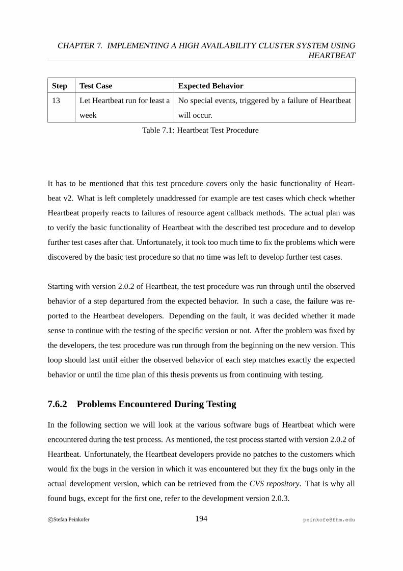
CHAPTER 7. IMPLEMENTING A HIGH AVAILABILITY CLUSTER SYSTEM USINGHEARTBEAT
Step Test Case Expected Behavior
13 Let Heartbeat run for least a
week
No special events, triggered by a failure of Heartbeat
will occur.
Table 7.1: Heartbeat Test Procedure
It has to be mentioned that this test procedure covers only the basic functionality of Heart-
beat v2. What is left completely unaddressed for example are test cases which check whether
Heartbeat properly reacts to failures of resource agent callback methods. The actual plan was
to verify the basic functionality of Heartbeat with the described test procedure and to develop
further test cases after that. Unfortunately, it took too much time to fix the problems which were
discovered by the basic test procedure so that no time was left to develop further test cases.
Starting with version 2.0.2 of Heartbeat, the test procedure was run through until the observed
behavior of a step departured from the expected behavior. In such a case, the failure was re-
ported to the Heartbeat developers. Depending on the fault, it was decided whether it made
sense to continue with the testing of the specific version or not. After the problem was fixed by
the developers, the test procedure was run through from the beginning on the new version. This
loop should last until either the observed behavior of each step matches exactly the expected
behavior or until the time plan of this thesis prevents us from continuing with testing.
7.6.2 Problems Encountered During Testing
In the following section we will look at the various software bugs of Heartbeat which were
encountered during the test process. As mentioned, the test process started with version 2.0.2 of
Heartbeat. Unfortunately, the Heartbeat developers provide no patches to the customers which
would fix the bugs in the version in which it was encountered but they fix the bugs only in the
actual development version, which can be retrieved from theCVS repository. That is why all
found bugs, except for the first one, refer to the development version 2.0.3.
c©Stefan Peinkofer 194 [email protected]
7.6. EVALUATION OF HEARTBEAT 2.0.X
7.6.2.1 Heartbeat Started Resources Before STONITH Completed
While performingtest step 4it was encountered that when a node triggered the STONITH of
the other node, it did not wait until the STONITH operation completed before it started to take
over the resource group of the other node. Therefore for a small period of time, the resources
were active simultaneously on both nodes, which led to data corruption. After reporting the bug
to the Heartbeat mail list, a developer responded that the problem is already known and fixed
in the currentCVS version. Unfortunately, it turned out that the problem was only fixed for
resources which are not contained in a resource group. After reporting this to the mail list, the
problem was fixed for the resources contained in a resource group as well.
7.6.2.2 The Filesystem Resource Agent Returned False Error Codes
With the new CVS version, which fixed problem 1, a new bug was introduced which was en-
countered bytest step 1. The callback functionsStatusandMonitor of the Heartbeat cluster
agentFilesystem, which is responsible for mounting and unmounting shared disks, returned
OCF_ERR_GENERICwhen the resource was not started yet. As discussed in chapter7.5.4.1
on page186, the right error code for this scenario would beOCF_NOT_RUNNING. Since Heart-
beat calls theMonitor method once before it calls theStart method, this caused Heartbeat not
to start the resource groups, since it assumes that a return code ofOCF_ERR_GENERICindi-
cates that a resource is unhealthy, even if it is not started yet. What happened is that each node
tried to start its resource group, which failed because of the wrong return code, so the resource
groups were failed over to the respective other node, on which the start of the resource group
failed as well, of course. After that, Heartbeat left the resource groups alone, to avoid further
ping-pong fail overs. Fortunately, the problem was easy to isolate and so a detailed description
to fix the bug was provided to the Heartbeat developers.
7.6.2.3 Heartbeat Could not STONITH a Node
Again, the new CVS version, which fixed problem 2, introduced a new bug, which was encoun-
tered bytest step 4. Apparently, Heartbeat was not able to carry out STONITH operations. The
c©Stefan Peinkofer 195 [email protected]
CHAPTER 7. IMPLEMENTING A HIGH AVAILABILITY CLUSTER SYSTEM USINGHEARTBEAT
cause of this problem was an unreasonable “if-condition“ in the STONITH code, which caused
the STONITH operation to return with an error before the actual STONITH command was
called. So what happened was that both nodes continuously tried to issue STONITH operations
to fence the other node, which failed. The problem was reported to the Heartbeat developers,
who fixed the unreasonable “if-condition“.
7.6.2.4 Heartbeat Stopped Resources in the Wrong Order
After problem 3 was fixed, it was encountered that the specific stop procedure of Heartbeat,
carried out intest step 9, stopped the resources in the resource group not in the right order,
but in a random one. After a basic fault analysis, it turned out that this behavior could only
be observed when Heartbeat was shut down on the last cluster member. The effects of this bug
were random; sometimes everything worked fine, sometimes the application data disk remained
mounted after Heartbeat was stopped. The problem was reported to the Heartbeat developers,
who included the problem in their bug database. A final solution is still pending, since it seems
that a fix will require a significant amount of work to be done.
7.6.2.5 STONITH Resources Failed After Some Time
The last problem which was encountered was very hard to analyze because the actual problem
cause was not Heartbeat itself but the deployed STONITH devices. Duringtest step 13, the
STONITH resources of the physical STONITH devices became inactive after some time. The
available Heartbeat log files showed that the monitoring function of the STONITH resource
timed out. After that Heartbeat stopped the STONITH resource and then tried to restart the
STONITH resource again, which failed. After 2 seconds, a log file message which said that the
STONITH daemon, which is responsible for carrying out all STONITH operations on the cor-
responding node, was killed because of asegmentation fault. Since thesegmentation fault log
messagewas not generated by the STONITH daemon itself but by Heartbeat, which monitors
its child processes and respawns them if they exit, we assumed that the segmentation fault of
the STONITH daemon actually happened already before the monitoring method timed out but
was logged only after the timeout. Therefore we assumed that the segmentation fault was the
c©Stefan Peinkofer 196 [email protected]
7.6. EVALUATION OF HEARTBEAT 2.0.X
initial cause of the problem. The Heartbeat developers said that they already knew this problem,
but were not able to reproduce it reliably and asked us if they could get access to our systems
to track the bug. So we gave them access to our machines and they fixed the segmentation fault
problem. Unfortunately, it turned out that the segmentation fault did not cause the problem, but
was only a consequence of it, since even with the fixed version of Heartbeat, the STONITH
resources still became inactive after some time; the only difference was that the STONITH dae-
mon caused no segmentation fault anymore.
After a short period of perplexity, we decided to concentrate on the timed out monitoring method
of the STONITH resource, which connects to the STONITH device over the network, calls the
help command and disconnects from the STONITH device. Since Heartbeat v1 provides a
command line tool, which performs the same procedure as the monitoring method, it was cho-
sen to exercise the STONITH device by continuously calling this tool in a loop. The intention
of this test was to figure out if the problem is caused by Heartbeat itself, by the STONITH code
or by the STONITH device6. At the beginning of this test, the monitoring command completed
within a second. After a short time period, the command took about 3 to 5 seconds to complete
and after another short period of time, the monitoring command completed unsuccessfully after
30 seconds. During this period, the monitoring function repeatedly printed out error messages,
which said that it was not able to log in to the STONITH device. After stopping the test after
this event, it was tried to ping the STONITH device and it didn’t respond to the ping request
anymore. Funnily enough, the STONITH device began to respond to the ping messages after
2 minutes again, which is the configured network connection timeout on the STONITH device
and the monitoring function could be called successfully again, too.
So the fault could be isolated to afirmware bugof the STONITH device. Unfortunately, the
manufacturer of the deployed STONITH devices does not provide firmware upgrades at all,
so the source problem could not be eliminated. Since the STONITH device recovered auto-
matically after 2 minutes, the last idea to work around the problem was to call the monitoring
6In fact no one expected that the problem could be caused by the STONITH device at this point.
c©Stefan Peinkofer 197 [email protected]

CHAPTER 7. IMPLEMENTING A HIGH AVAILABILITY CLUSTER SYSTEM USINGHEARTBEAT
function in time intervals higher than 2 minutes. Unfortunately, it turned out that even with a
time interval of 4 minutes, the problem still occurred. The only difference was that it occurred
not after some minutes but after some days. So it was decided to replace the STONITH devices
with other ones. After an evaluation of which other STONITH devices are supported by Heart-
beat and which of them provide the ability to connect to at least two different power sources so
the power source of a node does not become a single point of failure, it turned out that only one
other STONITH device can be used7. Unfortunately, it turned out that this STONITH device is
hard to get in Germany and so it didn’t arrive in time for this thesis.
Since this version of Heartbeat passed the test procedure in a tolerable manner, because ex-
cept for the STONITH resource problem which was not caused by Heartbeat and the resource
stop problem, which occurs only under rare circumstances, the whole test procedure could be
completed successfully, it was decided to stop the tests at this point. It has to be mentioned
that the CVS version will not be used if this system goes into production use. Therefore the
test process cannot be considered finished since because of the ongoing development it is very
likely that new bugs are introduced. At least after the announcement of thefeature freezefor
the next stable Heartbeat version, the test process has to be run through again. Unfortunately,
this was not possible because the feature freeze was announced too late for this thesis.
7In fact there was a second one but it is not available anymore because production was discontinued.
c©Stefan Peinkofer 198 [email protected]
Chapter 8
Comparing Sun Cluster with Heartbeat
In the following sections we will look at the differences and similarities between Sun Cluster
and Heartbeat. Thereby we will limit our discussion to a high-level comparison, since compar-
ing the two products on the implementation level would be like comparing apples and oranges.
The first section will be limited to the comparison of the pure Cluster Software. Since a high
availability cluster solution has to be seen as a complete system, consisting of hardware, op-
erating system and cluster software, we will look at further pros and cons that result from the
concrete system composition:
• Sun Cluster - Solaris - SPARC hardware
• Heartbeat v2 - Linux - x86 hardware
8.1 Comparing the Heartbeat and Sun Cluster Software
The following section will discuss the benefits and drawbacks of Heartbeat and Sun Cluster.
8.1.1 Cluster Software Features
• Maximum number of cluster nodes- Sun currently officially limits the number of sup-
ported nodes to 16. However, parts of the cluster software, like theglobal device file
systemare obviously already prepared for 64 nodes. So it seems to be very likely that Sun
199
CHAPTER 8. COMPARING SUN CLUSTER WITH HEARTBEAT
Cluster will support 64 nodes with one of the next software releases. Heartbeat v2 has no
limitation of the number of cluster nodes. At the time of this writing, Heartbeat has been
verified to run on a 16-node cluster.
• Supported Operating Systems- Sun Cluster can only be deployed on Solaris for SPARC
and Solaris for x86 whereby the x86 version provides only a subset of the features from
the SPARC version. The limitation to Solaris results mainly from the tight integration
of Sun Cluster and the Solaris kernel. Although Heartbeat is also called theLinux-HA
project, it is not limited to the use of Linux as operating system. Heartbeat is also known
to run on FreeBSD, Solaris and MacOS X. In fact, when Heartbeat can be compiled
cleanly on an operating system there are good chances that it will also run on the cor-
responding OS. One person even tried to cluster Windows servers by using Heartbeat
in the cygwinenvironment. Unfortunately it is not known whether the experiment was
successful or not.
• Supported Shared File Systems- As we already know, Sun Cluster supports theSun
Cluster proxy file systemand theSun QFS SAN file systemas shared cluster file systems.
At the time of this writing, Heartbeat currently does not support any shared file system.
This does not necessarily mean that Heartbeat won’t work with a shared file system;
it only means that Heartbeat requires the user to find out whether Heartbeat works in
conjunction with a specific shared file system or not. However, the Heartbeat developers
plan to support theOracle ClusterFile System(OCFS) 2, which is distributed under the
terms of the GNU Public License, with one of the next Heartbeat releases.
• Out-of-the-box Cluster Agents- Heartbeat v2 currently only ships with OCF resource
agents forApache, DB2, IBM WebsphereandXinetd. Sun Cluster currently provides 32
cluster agents, which support, amongst others,Oracle RAC (Real Application Cluster,
SAP, IBM WebsphereandSiebel.
c©Stefan Peinkofer 200 [email protected]
8.1. COMPARING THE HEARTBEAT AND SUN CLUSTER SOFTWARE
8.1.2 Documentation
Sun provides a comprehensive set of documentation, which is comprised of a few thousand
pages. Despite the great size of the documentation, it is well structured in several documents,
so the right documentation for a particular topic can be retrieved relatively quickly and the docu-
mentation is always kept up-to-date. The documentation itself is mainly written asstep-by-step
instructions which lead the user straight to the desired goal. The only drawback, which is in
fact only experienced by expert users, is that the documentation does not always describe how
particular tasks are carried out by Sun Cluster in detail. But since this knowledge is usually not
needed to build a “supported“ Sun Cluster system it may be legitimate from a normal user’s
point of view. In addition to the general Sun Cluster documentation, a comprehensive “on-line“
help guide for the various cluster commands is available in the form of UNIX man pages.
The Heartbeat documentation provides great room for improvement. First of all, the avail-
able documentation is very unstructured, which makes it very time consuming to retrieve the
information for a particular topic. Second, only one documentation set for all available Heart-
beat versions exists, which makes it in some cases very hard to determine whether particular
information is valid for the concrete Heartbeat version deployed. Third, the documentation
leaves some important topics either completely unaddressed or contains only a subset of the
needed information. Fourth, Heartbeat provides virtually no “on-line“ help for the various
cluster commands. The only advantage of the Heartbeat documentation is that it provides some
information about how certain things are implemented, which are of course not very useful for
users who just want to build a Heartbeat cluster, but are very interesting to people who want to
learn something about how a high availability system could be implemented.
8.1.3 Usability
Sun Cluster provides a comprehensive set of command line tools which can be used to con-
figure and maintain the cluster system. The common command line options of the tools are
named consistently throughout all commands, which eases the use of the tools and after a short
c©Stefan Peinkofer 201 [email protected]
CHAPTER 8. COMPARING SUN CLUSTER WITH HEARTBEAT
adaptation phase, the commands can be used nearly intuitive1. In addition to that, the command
line tools prevent the user from accidentally misusing the tools, by verifying whether the ef-
fects caused by the execution of the specific command are sensible or not. In addition to the
command line tools, the Sun Cluster software also provides a graphical user interface for con-
figuring and maintaining the cluster. However, not all possible tasks can be carried out by the
graphical user interface, but for configuring a cluster and for performing normal “day-to-day“
tasks, the graphical user interface should be sufficient. In addition to that, the SUN Cluster
software provides an easy to use graphical user interface which allows even users with virtually
no programming experience to create custom cluster agents.
The command line tools provided by Heartbeat are still evolving. In Heartbeat version 2.0.2
even some important command line tools, like a tool which allows the user to switch individ-
ual resource groups on- and offline, were missing. However, version 2.0.3 will introduce the
missing commands. Compared to the Sun Cluster command line tools, the tools provided by
Heartbeat are more complex to use. Another drawback in the usability of Heartbeat is that a user
needs programming experience to create a cluster agent. However, the greatest drawback in the
usability of Heartbeat is the configuration of the Cluster Information Base, since the structure
of the XML file is very complex and it provides an overwhelming number of set screws which
probably ask too much of a not so experienced user. Fortunately, this drawback was already
recognized by the Heartbeat developers and so they are currently developing a graphical user
interface for configuring Heartbeat and the Cluster Information Base.
8.1.4 Cluster Monitoring
Sun Cluster provides a cluster monitoring functionality by using a Sun Cluster module for the
general purpose monitoring and management platformSun Management Center. Heartbeat
itself provides only a simple, text oriented monitoring tool. However, through the use of ad-
ditional software components like theSpumoniprogram, which enables virtually any program
1Yes, command line tools can be intuitive, at least to UNIX gurus.
c©Stefan Peinkofer 202 [email protected]
8.1. COMPARING THE HEARTBEAT AND SUN CLUSTER SOFTWARE
which can be queried via local commands to be health-checked via SNMP, Heartbeat can be
integrated in enterprise level monitoring programs likeHP OpenViewor OpenNMS.
8.1.5 Support
In the following we will compare the support which is available for the discussed cluster prod-
ucts. Therefore, we will look first at the support which is available at no charge and then at the
additional support through commercial support contracts.
8.1.5.1 Free Support
Sun provides two sources for free support for the Sun Cluster software. Source one is aknowl-
edge databasecalledSunSolve. This database provides current software patches as well as in-
formation of already known bugs and troubleshooting guides for common problems. However,
the knowledge base does not contain all the information which is contained in Sun’s internal
knowledge base and therefore for some problems, it is necessary to consult the Sun support to
get information about how to fix the problem.
The second source is aWeb forumfor Sun Cluster users. Registered users can post their ques-
tions to the forum but use of this forum seems to be very limited, since most of the questions to
which users have replied could easily have been answered by the SunSolve knowledge database
and to most of the questions which could not be answered by SunSolve, users have not replied.
The Heartbeat community provides free support over their Heartbeatuser mailing list, which is
also available as a searchable archive. In addition to the mailing list, a HeartbeatIRC channel
exists, over which a user can get in touch with the Heartbeat developers in real time. Questions
to the mailing list are usually answered within 24 hours, whereby most of the questions are
directly answered by the Heartbeat developers themselves, who are very friendly and patient2.
If response time is no issue, the quality of support, provided through the mailing list, can be
2A factor which is not self-evident in Open Source and commercial software forums.
c©Stefan Peinkofer 203 [email protected]

CHAPTER 8. COMPARING SUN CLUSTER WITH HEARTBEAT
compared to the quality of the commercial telephone support for Sun Cluster.
8.1.5.2 Commercial Support
Sun provides two commercial support levels for the Sun Cluster software,standard leveland
premium levelsupport, whereby the support is already included in the license costs for the
software. The standard support level allows the user to submit support calls during extended
business hours which are 12 hours from Monday to Friday. The reaction time3 depends on the
priority of the support call and is 4 hours for high priority, 8 hours for medium priority and 24
hours for low priority support calls. The premium support level allows the user to submit sup-
port calls 24 hours a day, 7 days a week. The reaction time is 2 hours for medium priority and 4
hours for low priority support calls. High priority support calls will be immediately transferred
to asupport engineer. In addition to this support, Sun offers the opportunity to place a contract
with SunsRemoteEnterpriseOperationServices Center(REOS) which will undertake the task
of doing the installation of the system as well as remote monitoring and administration tasks.
The Heartbeat community itself does not provide commercial support. However, third par-
ties like IBM Global Services or SUSE/Novell provide the ability to place support contracts for
Heartbeat. SUSE for example provides various support levels for their SUSE Linux Enterprise
distribution, which includes support for Heartbeat. Unfortunately, currently only Heartbeat
v1 is supported by SUSE, since the SUSE Linux Enterprise distribution does not yet contain
Heartbeat v2. The support levels vary from support during normal business hours and 8 hours
response time, to 24/7 support with 30 minutes response time. The costs for this support varies
from 8,100 EUR to 343,000 EUR per year whereby the support seems to enfold all SUSE En-
terprise Linux installations of the organization. In addition to this support, SUSE provides also
a remote management option, which is very similar to Sun’s REOS.
3This is the time interval which is allowed to elapse between the point in time the support call is submitted and
the point in time a support engineer responds to the call.
c©Stefan Peinkofer 204 [email protected]

8.1. COMPARING THE HEARTBEAT AND SUN CLUSTER SOFTWARE
8.1.6 Costs
Currently, the license costs for Sun Cluster constitute 50 EUR per employee per year, which
includes standard support for the Sun Cluster software. For premium support, the license costs
are 60 EUR. In addition to that, Sun charges further license costs for some cluster agents. Since
Heartbeat is distributed under the terms of the GNU Public License, it is available at no cost.
8.1.7 Cluster Software Bug Fixes and Updates
Bugs encountered in a specific Sun Cluster version are fixed by applying patches, which are
provided by Sun over the SunSolve knowledge base. Therefore bug fixes can be applied with-
out upgrading the software to a new version, whereby nearly all patches can be applied by a
rolling upgrade process. For Sun Cluster version updates, a distinction must be made between
minor andmajor version updates. Minor version updates, which are denoted by extending the
version number by the release date of the update, can be performed by a rolling upgrade pro-
cess. Major version updates, for example from version 3.0 to 3.1, require the shutdown of the
whole cluster and therefore cannot be applied by a rolling upgrade process. The same is true for
updates of the Solaris operating system. This is caused by the tight integration of Sun Cluster
and the Solaris kernel.
Bugs encountered in a specific Heartbeat version cannot be fixed by applying patches, since
the Heartbeat developers do not provide patches. The only chance to fix the bug is to deploy
a successor version which does not contain the bug. This can mean that if no stable successor
version exists yet, either the unstable CVS version has to be used or the user must wait until the
next stable version is released. The only way to get around this problem would be to use a Linux
distribution which providesback portsof recent bug fixes, for the Heartbeat version which was
shipped with the Linux distribution. All Heartbeat version updates, except the update fromv1
to v2, can be performed by a rolling upgrade process. In addition to that, all types of operating
system updates can be performed by a rolling update process, too, since Heartbeat is decoupled
from the deployed operating system kernel.
c©Stefan Peinkofer 205 [email protected]

CHAPTER 8. COMPARING SUN CLUSTER WITH HEARTBEAT
8.2 Comparing the Heartbeat and Sun Cluster Solutions
In the following sections we will look at further benefits and drawbacks which result from
the concrete combination of Heartbeat together with Linux on x86 hardware and Sun Cluster
together with Solaris on SPARC hardware.
8.2.1 Documentation
Although the documentation of Linux and x86 hardware is not as bad as the Heartbeat doc-
umentation, the documentation of Solaris and SPARC hardware is still better. This is mainly
founded on the fact that all documentation of Sun Cluster, Solaris and SPARC servers can be
accessed over a common Web site, which is well structured and covers all important issues in
step-by-stepguides. In addition to that, the Solaris “on-line“ help, provided by UNIX man
pages, provides far more information than the man pages of Linux and in contrast to Linux,
Solaris provides a man page for every command line and graphical application.
8.2.2 Commercial Support
Since virtual identically support contracts can be placed for Linux and x86 servers as well as
for Solaris and SPARC servers, no differences in the available support levels exist. However,
the SPARC solution provides one advantage: The support of the overall system is provided by
a single company whereas for the x86 solution, at least two companies are involved, namely the
company which provided the hardware and the company which provided the Linux distribution.
Theoretically this should constitute no drawback, but in the real world it occurs from time to
time that a support division of a company shifts the responsibility on to the support division of
another company and the other way round. For example, consider a failure scenario in which
a server reboots from time to time without giving a hint of what caused the problem. The
company which provides the support for Linux will begin with saying that this is not caused by
Linux but by the server hardware, and the company which provides the support for the hardware
will say it is caused by Linux. So to get support at all, the customer must first prove that the
c©Stefan Peinkofer 206 [email protected]
8.2. COMPARING THE HEARTBEAT AND SUN CLUSTER SOLUTIONS
problem is caused by either Linux or the server hardware. With a SPARC solution, the task of
determining which component caused the failure is totally relinquished to the Sun support.
8.2.3 Software and Firmware Bug Fixes
The main advantage of the SPARC solution for software and firmware patches is that all re-
quired patches can be downloaded from a common Web page. In addition to that, Sun usually
keeps track of patch revision dependencies between the cluster software, the operating sys-
tem and firmware patches and notifies users about this dependencies in the respective patch
documentation. Since with a Linux solution, at least two companies are always involved, the
operating system and firmware patches have to be downloaded from two different places and it
is not guaranteed that the companies keep track of dependencies between their patches and the
patches of other companies.
8.2.4 Costs
The overall costs for servers and operating system for a x86 solution should be about 10 to 20
percent lower than the costs for a comparable SPARC solution. This is because of the slightly
higher hardware costs for SPARC systems, since license costs are demanded neither for Linux
nor for Solaris.
8.2.5 Additional Availability Features
The use of midrange and enterprise level SPARC servers in conjunction with Solaris provides
further availability features. This features are discussed in the following section.
• Hot plug PCI bus - PCI devices can be removed and added without rebooting the system.
Indeed, some x86 servers provide this feature too, but not all PCI cards, available for
x86 severs support this feature and using the hot plug functionality with Linux is more
complex than with Solaris.
c©Stefan Peinkofer 207 [email protected]
CHAPTER 8. COMPARING SUN CLUSTER WITH HEARTBEAT
• Hot plug memory and CPUs- Memory and CPUs can be removed and added without
rebooting. Although it seems that some x86 systems support this feature4, the Linux
support for hot plug memory and CPUs is still in the alpha state.
• Automatic recovery from CPU, memory and PCI device failures- If one of the men-
tioned components fail, the system will be rebooted by a kernel panic. During the reboot,
the failed component will be unconfigured and the system will restore system operation
without using the failed component. Unfortunately, no information about whether x86
systems provide such a functionality could be found.
8.2.6 “Time to Market“
Assuming that Heartbeat v2 works as expected, the overall time which is currently needed to
design and configure a Sun Cluster system is less than the time which is needed to build a
Heartbeat v2 system. This is mainly caused by the lack of documentation of the Heartbeat
software. However, assuming that the documentation of Heartbeat is as good as the documen-
tation for Sun Cluster, the time to market for a simple cluster configuration which does not use
a shared file systemandsoftware mirrored shared disksand which does not require the devel-
opment of a cluster agent would be approximately the same for both system types. For more
complex cluster configurations, thetime to marketshould be less for Sun Cluster since these
configurations can be implemented in a very straightforward way, whereas a Linux - Heartbeat
combination usually requires the user to perform complex configuration tasks to implement a
complex configuration.
8.3 Conclusion
As we have seen, the harnessed team Sun Cluster, Solaris and SPARC provides a comprehen-
sive high availability cluster solution, which is mature and reliable enough to be deployed in a
production environment. However, if commercial support from Sun is required it is mandatory
4For example the ES7000 servers from Unisys.
c©Stefan Peinkofer 208 [email protected]
8.3. CONCLUSION
that the concrete cluster configuration matches all special configuration constraints of the vari-
ous applications.
For the harnessed team Heartbeat v2, Linux and x86, things look different yet. As we have
seen, Heartbeat v2 still contains too many bugs and the documentation is not good enough.
However, with the basic design of Heartbeat v2 and the already planned improvements, Heart-
beat v2 has the potential to become the best freely available cluster solution which does not
need to hide from commercial cluster systems. If the documentation of Heartbeat is improved,
there will be no reason not to deploy a Heartbeat v2 cluster in a production environment. So
it is worth it to keep an eye on the evolution of Heartbeat v2. Linux and the x86 hardware
lack still some high availability features which are desirable in midrange and enterprise scale
configurations and the features already available are complicated to configure and to use. How-
ever, since many big companies like IBM, Red Hat and SUSE/Novell enforce Linux and x86 as
an enterprise suitableoperating system - hardware combination, it can be expected that these
things will improve over time.
c©Stefan Peinkofer 209 [email protected]
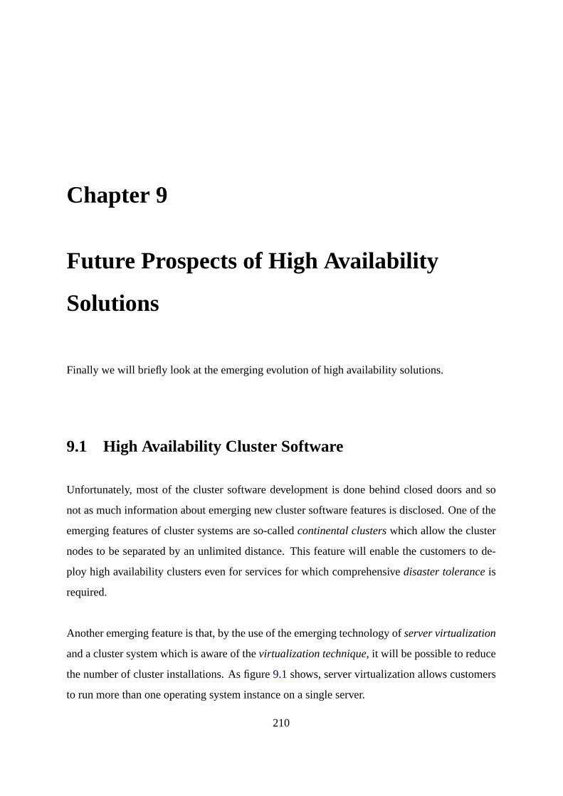
Chapter 9
Future Prospects of High Availability
Solutions
Finally we will briefly look at the emerging evolution of high availability solutions.
9.1 High Availability Cluster Software
Unfortunately, most of the cluster software development is done behind closed doors and so
not as much information about emerging new cluster software features is disclosed. One of the
emerging features of cluster systems are so-calledcontinental clusterswhich allow the cluster
nodes to be separated by an unlimited distance. This feature will enable the customers to de-
ploy high availability clusters even for services for which comprehensivedisaster toleranceis
required.
Another emerging feature is that, by the use of the emerging technology ofserver virtualization
and a cluster system which is aware of thevirtualization technique, it will be possible to reduce
the number of cluster installations. As figure9.1shows, server virtualization allows customers
to run more than one operating system instance on a single server.
210

9.1. HIGH AVAILABILITY CLUSTER SOFTWARE
R1
R3
R2
R4
Virtual Hosts
Physical Hosts
Cluster Application Cluster Application
Figure 9.1: High Availability Cluster and Server Virtualization
If the cluster system is aware of the underlying virtualization technique, it will be possible to
deploy a single cluster instance which maintains all services, contained in the various operating
system instances. As figure9.2 shows, to make these services highly available, the cluster
system will no longer fail over the application instance, but fail over the whole virtual operating
system instance.
c©Stefan Peinkofer 211 [email protected]
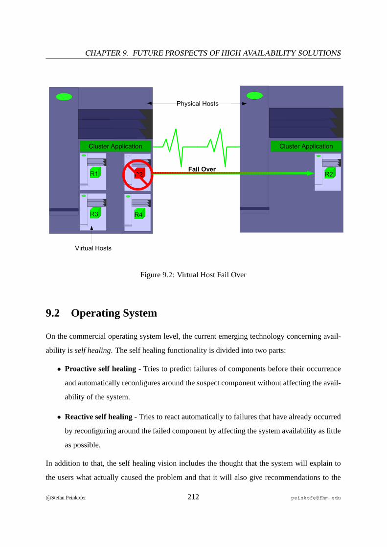
CHAPTER 9. FUTURE PROSPECTS OF HIGH AVAILABILITY SOLUTIONS
R1
R3
R2
R4
Virtual Hosts
Cluster Application Cluster Application
R2 Fail Over
Physical Hosts
Figure 9.2: Virtual Host Fail Over
9.2 Operating System
On the commercial operating system level, the current emerging technology concerning avail-
ability is self healing. The self healing functionality is divided into two parts:
• Proactive self healing- Tries to predict failures of components before their occurrence
and automatically reconfigures around the suspect component without affecting the avail-
ability of the system.
• Reactive self healing- Tries to react automatically to failures that have already occurred
by reconfiguring around the failed component by affecting the system availability as little
as possible.
In addition to that, the self healing vision includes the thought that the system will explain to
the users what actually caused the problem and that it will also give recommendations to the
c©Stefan Peinkofer 212 [email protected]
9.3. HARDWARE
user regarding what should be done to fix the problem. If these recommendations are reliable
enough, themean time to repaircan be reduced, since the task to find a solution for the problem
is already done by the system itself.
On the non-commercial operating system level, we can expect that more and more of the avail-
ability features which are currently available on the commercial operating systems will be im-
plemented and that the configuration and administration of these features will be as easy as they
are on the commercial operating systems.
9.3 Hardware
On the hardware level, we can expect that the reliability of hardware components will improve
over time. In addition to that, more and more availability features, which are currently only
available for midrange and enterprise scale hardware, will also be available for entry level hard-
ware. Also, the complexity of the configuration and administration of hardware components
like storage sub-systemsor Ethernet switchesandrouterswill be reduced.
c©Stefan Peinkofer 213 [email protected]
Appendix A
High Availability Cluster Product
Overview
TableA.1 gives an overview of the most important high availability cluster products.
214

HA
CM
PH
eart
beat
HP
Ser
vice
guar
d
Vend
orIB
MO
pen
Sou
rce
Hew
lett-
Pac
kard
Ope
ratin
gS
yste
m(s
)A
IXLi
nux,
Sol
aris
,Fre
eBS
D,M
acO
SX
,oth
ersH
P-U
X,L
inux
Har
dwar
eP
ower
PC
x86,
SP
AR
C,P
ower
PC
,oth
ers
Itani
um,P
A-R
ISC
,x86
Num
ber
ofN
odes
32no
tlim
ited
16
Web
http
://w
ww
.ibm
.com
http
://w
ww
.linu
x-ha
.org
http
://w
ww
.hp.
com
IRIS
aF
ailS
ave
Life
keep
erLi
nux
Fai
lSav
eb
Vend
orS
GI
Ste
elE
yeTe
chno
logy
Ope
nS
ourc
e(S
GIo
rigin
ally
)
Ope
ratin
gS
yste
m(s
)IR
IXLi
nux,
Win
dow
s(N
T,20
00,2
003)
Linu
x
Har
dwar
eM
IPS
x86,
Pow
erP
Ccx8
6,(m
aybe
othe
rsto
o)
Num
ber
ofN
odes
832
16
Web
http
://w
ww
.sgi
.com
http
://w
ww
.ste
eley
e.co
m/
http
://os
s.sg
i.com
Red
Hat
Clu
ster
Sui
teS
unC
lust
erW
indo
ws
Clu
ster
Vend
orR
edH
atS
unM
icro
syst
ems
Mic
roso
ft
Ope
ratin
gS
yste
m(s
)R
edH
atLi
nux
Sol
aris
Win
dow
s(N
T,20
00,2
003)
Har
dwar
ex8
6S
PA
RC
,x86
x86
Num
ber
ofN
odes
1616
8d
Web
http
://w
ww
.red
hat.c
omht
tp://
ww
w.s
un.c
omht
tp://
ww
w.m
icro
soft.
com
Tabl
eA
.1:
Hig
hA
vaila
bilit
yC
lust
erP
rodu
cts
aN
ote
that
this
isno
typo
.bT
hede
velo
pmen
toft
his
prod
ucti
sdi
scon
tinue
d.c L
inux
only
.dF
orfa
ilov
erco
nfigu
ratio
ns.
c©Stefan Peinkofer 215 [email protected]

Nomenclature
API Application Programming Interface
ARP Address Resoluation Protocol
ATA Advanced Technology Attachments
BIOS Basic Input/Output System
CIB Cluster Information Base
CIFS Common Internet File System
CPU Central Processing Unit
CRC Cyclic Redundancy Check
CRM Cluster Resource Manager
CTS Cluster Test System
CV S Concurrent Versions System
DC Designated Coordinator
DNS Domain Name System
DTD Document Type Definition
ECC Error Correction Code
FC Fibre Channel
GNU GNU’s Not Unix
HA High Availability
HBA Host Bus Adapter
HP Hewlett-Packard
HTTP Hypertext Transfer Protocol
216
IBM International Business Machines
ICMP Internet Control Message Protocol
IEEE Institute of Electrical and Electronics Engineers
IP Internet Protocol
IPMP IP Multipathing
IRC Internet Relay Chat
ISO International Organization for Standardization
LAN Local Area Network
LDAP Lightweight Directory Access Protocol
LUN Logical Unit Number
MAC Media Access Control
MB Megabyte
MD Multi Disk
MPXIO Multiplex Input/Output
MTBF Mean Time Between Failure
MTTR Mean Time To Repair
NFS Network File System
NIS Network Information System
NTP Network Time Protocol
OCF Open Cluster Framework
OCFS Oracle Cluster File System
OS Operating System
OSI Open Systems Interconnection
PCI Peripheral Component Interconnect
PERL Practical Extraction and Report Language
PMF Process Management Facility
c©Stefan Peinkofer 217 [email protected]

APPENDIX A. HIGH AVAILABILITY CLUSTER PRODUCT OVERVIEW
PXFS Proxy File System
QFS Quick File System
RAC Real Application Cluster
RAID Redundant Array of Independent Disks
REOS Remote Enterprise Operation Services Center
RFC Requests for Comments
ROM Read Only Memory
RPC Remote Procedure Call
RTR Resource Type Registration
SAM Storage and Archive Manager
SAN Storage Area Network
SCI Scalable Coherent Interconnect
SCSI Small Computer System Interface
SMART Self-Monitoring, Analysis and Reporting Technology
SNMP Simple Network Management Protocol
SPARC Scalable Processor Architecture
SPOF Single Point Of Failure
SQL Structured Query Language
STOMITH Shoot The Other Machine In The Head
STONITH Shoot The Other Node In The Head
SV M Solaris Volume Manager
TCP Transmission Control Protocol
UDP User Datagram Protocol
UFS Unix File System
V HCI Virtual Host Controller Interconnect
V LAN Virtual Local Area Network
c©Stefan Peinkofer 218 [email protected]

V MS Virtual Memory System
WAN Wide Area Network
WLAN Wireless Local Area Network
WWN World Wide Name
XML Extensible Markup Language
ZaK Zentrum für angewandte Kommunikationstechnologien
c©Stefan Peinkofer 219 [email protected]

Bibliography
[ANON1] Anonymous, Reliability and Failure
[ANON2] Anonymous, Live system upgrades
[ANON3] Anonymous, High Availability Whitepaper
[ANON4] Anonymous, Fault Isolation
[ANON5] Anonymous, Disaster Recovery Plan of the University of Arkansas
[ANON6] Anonymous, Disaster Recovery Planning
[ANON7] Anonymous, Sun Cluster Data Services Planning and Administration Guide for So-laris OS
[ANON8] Anonymous, Solaris VolumeManager Administration Guide
[ANON9] Anonymous, Solaris man pages (man mediator)
[ARPACI] Arpaci, Remzi H., Communication Behavior of a Distributed Operating System
[BENDER] Bender William J., Joshi Abhinav, High Availability Technical Primer
[BENEDI] Benediktsson Oddur, Fault, failure and error
[BIANCO] Bianco Joseph, Lees Peter, Rabito Keven, SUN CLUSTER 3 Programming, Pren-tice Hall PTR, 2004, ISBN: 0130479756
[ELLING] Elling Richard, Read Tim, Designing Enterprise Solutions with Sun Cluster 3.0,Prentice Hall PTR, 2002, ISBN: 0130084581
[HELD1] Held Andrea, Grundlagen der Hochverfügbarkeit
[HELD2] Held Andrea, Hochverfügbarkeit: Kennzahlen und Metriken
[KAKADIA] Kakadia Deepak, Halabi Sam, Cormier Bill, Enterprise Network Design Patterns:High Availability, Sun Blueprints
[KOPPER] Kopper Karl, The Linux Enterprise Cluster, No Starch Press, 2005, ISBN:1593270364
220
BIBLIOGRAPHY
[KRAMER] Kramer, Shoshani, Agarwal, Draney, Et al, Deep scientific computing requiresdeep data
[KRONEN] Kronenberg Nancy P., Levy Henry M., Strecker Wiliam D.,VAXclusters: AClosely-Coupled Distributed System
[MARCUS] Marcus Evan, Stern Hal, Blueprints for High Availability, John Wiley & Sons Inc.,2004, ISBN: 0471356018
[MELLOR] Mellor Chris, Hitting the buffers/Fibre Channel buffers inhibit long-distance
[MENEZES] Menezes Telmo, Costa Diamantino, Tavares Miguel, On the Extension of Xcep-tion to Support Software Fault Models
[MOREAU] Moreau Ken, A Survey of Cluster Technologies
[PARABEL] Parabel Matthias, Disk-Backup kann ein Sicherheitsrisiko sein
[PFISTER] Pfister Gregory F., In Search of Clusters, Prentice Hall PTR, 1998, ISBN:0138997098
[RAHNAMAI] Rahnamai K., Arabshahi P., Yan T.-Y., Pham T., Finley S. G., An IntelligentFault Detection and Isolation Architecture For Antenna Arrays
[SMITH] Smith Jerry, What is two-phase commit?
[SNOOPY] Snoopy, Igor,der Schalter,Igor,der Schalter!!!, UpTimes, September 2005
[SOLTAU] Soltau Michael, Unix/Linux Hochverfügbarkeit, MITP, 2002, ISBN: 3826607759
[STALKER] Stalker Software Inc, Cluster Technology and File Systems
[STOCK] Stockebrand Benedikt, Zuverlässigkeit vor, hinter, unter und über dem Cluster, Up-Times, September 2005
[WIKI1] Anonymous, Computer cluster
[YOSHITAKE] Yoshitake Shinkai, Yoshihiro Tsuchiya, Takeo Murakami, Alternatives of Im-plementing a Cluster File Systems
c©Stefan Peinkofer 221 [email protected]