Embed Size (px)
Citation preview
012-01
ATALANTE 2004 Nîmes (France) June 21-25, 2004 1
Designing and Demonstration of the UREX+ Process Using Spent Nuclear Fuel
George F. Vandegrift, Monica C. Regalbuto, Scott Aase, Allen Bakel, Terry J. Battisti,* Delbert Bowers, James P. Byrnes, Mark A. Clark, Dan G. Cummings,* Jeff W. Emery, John R. Falkenberg, Artem V. Gelis,
Candido Pereira, Lohman Hafenrichter, Yifen Tsai, Kevin J. Quigley, and Mark H. Vander Pol
Chemical Engineering Division, Argonne National Laboratory, 9700 S. Cass Ave., Argonne IL, USA, 60439-4837, [email protected]
*Analytical Laboratory, Argonne National Laboratory, Idaho Falls, ID, USA 83402
Abstract – As part of the Advanced Fuel Cycle Initiative, Argonne National Laboratory demonstrated the UREX+ process using a 2-cm centrifugal contactor. The UREX+ process consisted of five solvent extraction processes that separated dissolved spent fuel into seven fractions. Following dissolution, uranium and technetium were recovered from the feed in separate product streams. Uranium was recovered in high yield (>99.9%) with a purity that would allow its disposal as nonTRU low-level waste; >99% of the Tc was recovered in high purity. In the next process, which was designed by researchers at INEEL, cesium and strontium were removed from the UREX raffinate. After feed adjustment, plutonium and neptunium were recovered in the NPEX process with high yield and impurity levels making it suitable for use as feed to MOX fuel. The raffinate of the NPEX process was fed to a TRUEX process where the minor actinides and rare-earth elements were recovered. The TRUEX product was fed directly to a Cyanex 301 process where minor actinides were purified from rare-earth elements. (Raffinates from the TRUEX and Cyanex 301 processes could be disposed separately or together.) Results of this demonstration and the AMUSE code used to design it will be discussed.
INTRODUCTION
The UREX+ process is being developed at Argonne National Laboratory (ANL) and other national laboratories under the Advanced Fuel Cycle Initiative (AFCI), funded by the U.S. Department of Energy’s Office of Nuclear Energy, Science and Technology [1]. At the end of Fiscal Year 2003, the complete UREX+ solvent extraction process was demonstrated using multistage, countercurrent centrifugal contactors in ANL's Chemical Engineering Division [2].
Processing Goals
The recovery and purification goals of the UREX+ process as set by the AFCI program are:
• Uranium recovery must be >90%. Its purity requirement would allow its disposal as low-level waste according to 10CFR61.55. The criterion to contain less than 100 nCi/g of TRU is the most difficult to meet, requiring a decontamination factor from plutonium of >105. If the uranium is destined for recycle in reactor fuel, its purity requirements are greater and would be governed by ASTM C 788-98.
• Technetium recovery must be >95% to provide a 20-fold decrease in off-site dose reduction. If transmutation of Tc is the chosen option, the Tc product must contain less than 16 µg of fissile actinides per g of Tc.
• Iodine recovery during fuel dissolution should be >95% to provide a 20-fold decrease in off-site dose reduction. If transmutation of I is the chosen option, the I product must contain less than 4 µg of fissile actinides per g of I.
• A 97% recovery is required for Cs and Sr to make their contributions to the heat load in the repository equal to that of all other fission products. The purity requirement for the Cs/Sr decay-storage form is 100 nCi/g TRU content to allow its ultimate disposal as low-level waste.
• Plutonium/neptunium recovery must be >99%. The purity of this product stream is required to meet mixed-oxide (MOX) fuel specifications as described in ASTM C833-01.
012-01
ATALANTE 2004 Nîmes (France) June 21-25, 2004 2
• Based on a 100-fold reduction of heat load to the repository, a recovery of 99.5% is required for americium and curium. Based on fast-reactor recycle of all TRU, the lanthanide content of the Am/Cm product must be <20mg/g uranium plus TRU.
• The two raffinates from the UREX+ process—TRUEX, containing all soluble fission products but Cs, Sr, Tc, I, and the rare earth elements, and Cyanex 301, containing the rare earth elements—will be converted to a solid for disposal in the repository. The recovery for each component listed above means that 100% minus that per cent recovery shows up in this solid, e.g., only 1% of Pu and 3% of Cs and Sr can be left in these raffinates.
Process Demonstration
The UREX+ process demonstration was run twice, initially with a simulated dissolved spent fuel derived from ORIGEN2 code data, and subsequently with a feed consisting of actual spent fuel that had been dissolved in nitric acid. For the actual-dissolved-fuel demonstration, a pin of irradiated Big Rock Point uranium oxide fuel was dissolved in nitric acid at elevated temperature and pressure. The volume and concentration of the initial nitric acid solution was adjusted to provide a uranium solution appropriate to the low-acid requirements of the UREX process. The composition of the fuel pin was calculated by John Stillman (ANL Nuclear Engineering Division) using the ORIGEN2 code with the following input: (1) burn-up of 29,600 MWd/MT, (2) initial enrichment of 4.6% 235U, (3) 1% gadolinium burnable poison, and (4) cooling time of 21 years. Additional input was derived from the known and assumed operating parameters of the Big Rock Point boiling water reactor. In preparation for dissolution, the fuel pin was chopped into 3- to 5-cm segments.
Three multistage 2-cm centrifugal contactors were used for this demonstration—one unit located in a shielded cell, a second in a glovebox, and a third in a vacuum-frame hood. Because of the presence of 137Cs, 90Sr, and 154Eu in the dissolved fuel, most of the UREX+ process had to be run in the shielded cell. Uranium and technetium were extracted from the dissolved fuel in the shielded cell; however, stripping of Tc and then U from the loaded UREX solvent was conducted in a glovebox and a hood,
respectively. The entire flowsheets for CCD-PEG (Cs and Sr removal), NPEX (Pu and Np removal), TRUEX (Am, Cm, and rare-earth-fission-product removal), and Cyanex-301 (separation of Am and Cm from the rare earths) were run sequentially in the same shielded-cell contactor. Extensive decontamination and refitting of feed and effluent stages and lines were required between each process demonstration. Because the solvent for the CCD-PEG process is denser than water, refitting and decontamination were a far greater effort before and after this process. The process flowsheets were designed for the number of stages available for use and therefore were not optimized for plant-scale processes. In addition, a plant would use continuous banks of contactors, and would not require refitting and decontamination between process segments.
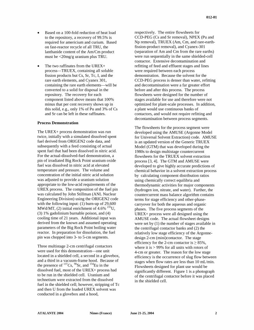
The flowsheets for the process segment were developed using the AMUSE (Argonne Model for Universal Solvent Extraction) code. AMUSE is an updated version of the Generic TRUEX Model (GTM) that was developed during the 1980s to design multistage countercurrent flowsheets for the TRUEX solvent extraction process [3, 4]. The GTM and AMUSE were developed to give highly accurate predictions of chemical behavior in a solvent extraction process by calculating component distribution ratios using chemically correct equilibria and thermodynamic activities for major components (hydrogen ion, nitrate, and water). Further, the countercurrent mass balance algorithm contains terms for stage efficiency and other-phase-carryover for both the aqueous and organic phases. The five process segments of the UREX+ process were all designed using the AMUSE code. The actual flowsheet designs were set by (1) the number of stages available in the centrifugal contactor banks and (2) the relatively low stage efficiency of the Argonne-design 2-cm (mini)contactor. The stage efficiency for the 2-cm contactor is ≥ 85%, where it is > 99% for all units with rotors of 4-cm or greater. The reason for the low stage efficiency is the occurrence of slug flow between stages when flow rates are less than 10 mL/min. Flowsheets designed for plant use would be significantly different. Figure 1 is a photograph of the centrifugal contactor before it was placed in the shielded cell.
012-01
ATALANTE 2004 Nîmes (France) June 21-25, 2004 3
UREX Segment
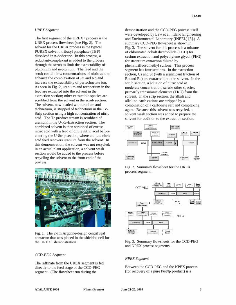
The first segment of the UREX+ process is the UREX process flowsheet (see Fig. 2). The solvent for the UREX process is the typical PUREX solvent, tributyl phosphate (TBP) dissolved in n-dodecane. In this process, a reductant/complexant is added to the process through the scrub to limit the extractability of plutonium and neptunium. The feed and the scrub contain low concentrations of nitric acid to enhance the complexation of Pu and Np and increase the extractability of pertechnetate ion. As seen in Fig. 2, uranium and technetium in the feed are extracted into the solvent in the extraction section; other extractible species are scrubbed from the solvent in the scrub section. The solvent, now loaded with uranium and technetium, is stripped of technetium in the Tc-Strip section using a high concentration of nitric acid. The Tc product stream is scrubbed of uranium in the U-Re-Extraction section. The combined solvent is then scrubbed of excess nitric acid with a feed of dilute nitric acid before entering the U-Strip section, where a dilute nitric acid feed recovers uranium from the solvent. In this demonstration, the solvent was not recycled; in an actual plant application, a solvent wash section would be added to the process before recycling the solvent to the front end of the process.
Fig. 1. The 2-cm Argonne-design centrifugal contactor that was placed in the shielded cell for the UREX+ demonstration.
CCD-PEG Segment
The raffinate from the UREX segment is fed directly to the feed stage of the CCD-PEG segment. (The flowsheet run during the
demonstration and the CCD-PEG process itself were developed by Law et al., Idaho Engineering and Environmental Laboratory (INEEL) [5].) A summary CCD-PEG flowsheet is shown in Fig. 3. The solvent for this process is a mixture of chlorinated cobalt dicarbollide (CCD) for cesium extraction and polyethylene glycol (PEG) for strontium extraction diluted by phenyltrifluoromethyl sulfone. This process segment has four sections. In the extraction section, Cs and Sr (with a significant fraction of Rb and Ba) are extracted into the solvent. In the scrub section, a solution of nitric acid at moderate concentration, scrubs other species, primarily transuranic elements (TRU) from the solvent. In the strip section, the alkali and alkaline-earth cations are stripped by a combination of a carbonate salt and complexing agent. Because this solvent was recycled, a solvent wash section was added to prepare the solvent for addition to the extraction section.
Fig. 2. Summary flowsheet for the UREX process segment.
Fig. 3. Summary flowsheets for the CCD-PEG and NPEX process segments.
NPEX Segment
Between the CCD-PEG and the NPEX process (for recovery of a pure Pu/Np product) is a
012-01
ATALANTE 2004 Nîmes (France) June 21-25, 2004 4
significant feed adjustment step. Feed adjust is required to (1) thermally destroy the reductant/complexant added in the UREX process to suppress extraction of plutonium and neptunium, (2) increase the concentration of nitric acid, and (3) convert and maintain plutonium and neptunium in the extractable (IV) oxidation state. In the demonstration, this procedure increased the volume of solution. However, in an operating plant this process would be done with extensive evaporation, and, therefore, volume reduction.
Following feed adjustment, the CCD-PEG raffinate is fed to the NPEX process (Fig. 3). The NPEX solvent composition is the same as for UREX, typical PUREX solvent. Impurities are removed from the solvent in the scrub section, and plutonium and neptunium are stripped using the same reductant/complexant that was fed to the scrub section of the UREX process. Because of the limited number of stages available to us in the shielded cell, there was no solvent wash or recycle of the solvent.
TRUEX Segment
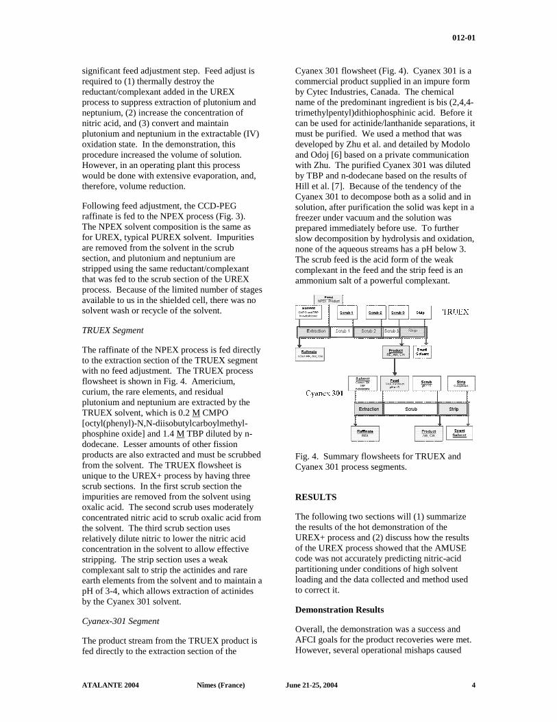
The raffinate of the NPEX process is fed directly to the extraction section of the TRUEX segment with no feed adjustment. The TRUEX process flowsheet is shown in Fig. 4. Americium, curium, the rare elements, and residual plutonium and neptunium are extracted by the TRUEX solvent, which is 0.2 M CMPO [octyl(phenyl)-N,N-diisobutylcarboylmethyl-phosphine oxide] and 1.4 M TBP diluted by n-dodecane. Lesser amounts of other fission products are also extracted and must be scrubbed from the solvent. The TRUEX flowsheet is unique to the UREX+ process by having three scrub sections. In the first scrub section the impurities are removed from the solvent using oxalic acid. The second scrub uses moderately concentrated nitric acid to scrub oxalic acid from the solvent. The third scrub section uses relatively dilute nitric to lower the nitric acid concentration in the solvent to allow effective stripping. The strip section uses a weak complexant salt to strip the actinides and rare earth elements from the solvent and to maintain a pH of 3-4, which allows extraction of actinides by the Cyanex 301 solvent.
Cyanex-301 Segment
The product stream from the TRUEX product is fed directly to the extraction section of the
Cyanex 301 flowsheet (Fig. 4). Cyanex 301 is a commercial product supplied in an impure form by Cytec Industries, Canada. The chemical name of the predominant ingredient is bis (2,4,4-trimethylpentyl)dithiophosphinic acid. Before it can be used for actinide/lanthanide separations, it must be purified. We used a method that was developed by Zhu et al. and detailed by Modolo and Odoj [6] based on a private communication with Zhu. The purified Cyanex 301 was diluted by TBP and n-dodecane based on the results of Hill et al. [7]. Because of the tendency of the Cyanex 301 to decompose both as a solid and in solution, after purification the solid was kept in a freezer under vacuum and the solution was prepared immediately before use. To further slow decomposition by hydrolysis and oxidation, none of the aqueous streams has a pH below 3. The scrub feed is the acid form of the weak complexant in the feed and the strip feed is an ammonium salt of a powerful complexant.
Fig. 4. Summary flowsheets for TRUEX and Cyanex 301 process segments.
RESULTS
The following two sections will (1) summarize the results of the hot demonstration of the UREX+ process and (2) discuss how the results of the UREX process showed that the AMUSE code was not accurately predicting nitric-acid partitioning under conditions of high solvent loading and the data collected and method used to correct it.
Demonstration Results
Overall, the demonstration was a success and AFCI goals for the product recoveries were met. However, several operational mishaps caused
012-01
ATALANTE 2004 Nîmes (France) June 21-25, 2004 5
less than optimized process behavior. For example, during the UREX segment, a leak developed in the scrub section during the run. The raffinate flow rate dropped from the prescribed value to 86% and finally to 74% of the value over the course of the run. The prescribed scrub flow rate was 67% of the raffinate flow rate. Assuming the drop in raffinate flow was primarily due to loss of aqueous scrub flow as the leak increased during the run, the “steady-state” samples collected at the end of the run were taken when the most of the scrub section and the entire extraction section saw a greatly decreased amount of complexant/reductant, leading to less plutonium decontamination of the U and Tc product than expected.
Another mishap was an inadvertent shutoff of the feeds to the scrub, strip, and acid wash sections of the CCD-PEG sections near the end of the run. Without these feeds entering the contactor, the solvent loaded with the alkali and alkaline-earth fission products was fed directly to the first extraction stage, resulting in contamination of the extraction stages. Not enough feed was left following the mishap to recover completely from this process upset, resulting in poor mass balance and process performance.
The bulk of the data collected during the demonstration was measured by ICP-MS (inductively coupled plasma-mass spectroscopy). Data were also collected by gamma and alpha-pulse measurements as appropriate. TIMS (thermal ionization mass spectrometry) was used for uranium and plutonium isotopic analysis for the dissolved-fuel solution and feed solution for the UREX+ process. Nitric acid was measured by titration, using oxalic acid to allow hydrogen-ion analysis with high concentrations of uranium in solution. The contents of organic samples were stripped into aqueous solutions before undergoing analysis.
The following subsections summarize how the effluent streams met the AFCI process goals. Details of the results can be found elsewhere [8].
U- and Tc -Products
Uranium recovery in the U-product stream was greater than 99.95%. Technetium recovery in the Tc-product was 95%. Impurities to the technetium product were primarily ruthenium and chemically unlikely barium. The fissile
content of Tc was experimentally equivalent to the target value. The fissile content was divided 65/35 U-235/Pu-239.
The fission products in the uranium product were far below the low-level waste (LLW) Class-C limits. However, the TRU limit was missed by a factor of 5, due to plutonium contamination resulting from the process upset. The uranium product contained a 2x10⁻⁴ fraction of the plutonium that was in the feed stream. Meeting the TRU limit required that the fraction be <4x10⁻⁵ of the initial plutonium be in the uranium product. A factor of 5 decreases could easily be achieved under planned operation. The U product from the FY 02 UREX demonstration at the Savannah River Technology Center [9] and the ANL simulant run both easily met the TRU waste limit.
Cs/Sr-Product
The Cs/Sr product contained 96% of the cesium and 99% of the strontium, and most of the Rb and Ba. However, mass balance calculations for the process segment showed that the flowsheet was far from steady state; more Cs and Sr were discharged from the effluents than was being fed to the process at the time when the samples were taken. This product contained over 50 times more TRU than allowed for non-TRU waste. The bad performance was due to an operational upset and should not be considered due to chemical or engineering uncertainties. This process will be demonstrated again in 2004 to show its efficacy.
Pu/Np-Product
The Pu/Np product contained 99.5% of the plutonium and 71% of the neptunium. The method used to maintain neptunium as Np(IV) in the NPEX segment was not successful; further development work is underway to better control the neptunium oxidation state. However, most of the Np lost to the raffinate in NPEX was recovered in the Cyanex 301 product, for a total recovery of >98%. The requirement for less than 3-mg lanthanides/g-heavy metal was easily met; the product contained <2x10⁻² mg-lanthanides/g of Pu/Np.
Am/Cm Product
The Cyanex-301 product contained >98% of the Am and >79% of the Cm. Given the large uncertainty in the Cm data, its recovery is almost
012-01
ATALANTE 2004 Nîmes (France) June 21-25, 2004 6
certainly equivalent to that of Am. Of major interest is the fractionation of the rare-earth elements in the Cyanex-301 process. Lanthanum, cerium, and praseodymium all reported to the Am/Cm product, while all the other rare earths acted as expected by not extracting [6, 7]. Recent data collected at INEEL, [10] and flowsheet modeling incorporating INEEL distribution-ratio data into AMUSE at ANL has shown that, although the lighter rare earths are considerably more extractable that the heavier rare earths, flowsheets can be easily designed to give complete separation of Am and Cm from all rare earths.
Combined Raffinates
The combined raffinates from TRUEX and the Cyanex-301 processes are bound for the repository. They should contain less than 5% of the uranium and technetium and 1 % of the TRU elements. They did contain <0.0006% of the uranium, 3.4% of the Tc, 0.02% of the Pu, <2% of Np, <0.04% of the Am, and <1.2% of the Cm.
HNO3 Distribution at High U Loadings
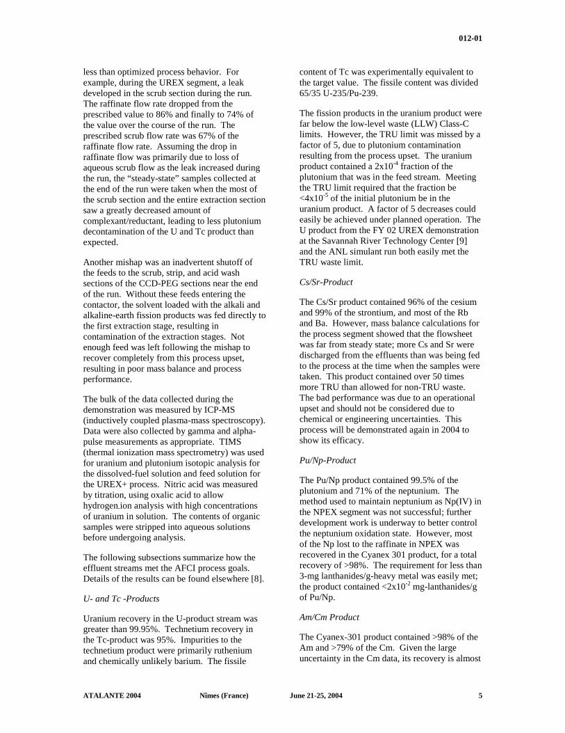
Stage samples of the organic and aqueous phases were collected after shutdown of the Tc-strip sections of the UREX process, and analyzed for metals by ICP-MS and hydrogen ion by titration. Shown in Fig. 5 are the measured and AMUSE-calculated stage profiles for hydrogen ion at the end of the demonstration. AMUSE predicted too high a stage concentration in both the organic and aqueous phases in the Tc-strip and acid-scrub sections (where uranium loading was high).
0.0
0.5
1.0
1.5
2.0
2.5
3.0
3.5
4.0
4.5
1 2 3 4 5 6 7 8 9 10 11 12 13 14 15 16 17 18 19 20 21 22 23 24 25 26 27 28 29 30 31 32 33Stage
[H],
M
Aqueous AMUSEOrganic AMUSEAqueous ExptOrganic Expt
U-RE-EXTRACTION
TC-STRIP
ACID SCRUB
Fig. 5. Experimentally-determined and AMUSE predicted stage concentration profiles for hydrogen ion in the Tc-strip sections prior to modification of the AMUSE loading module.
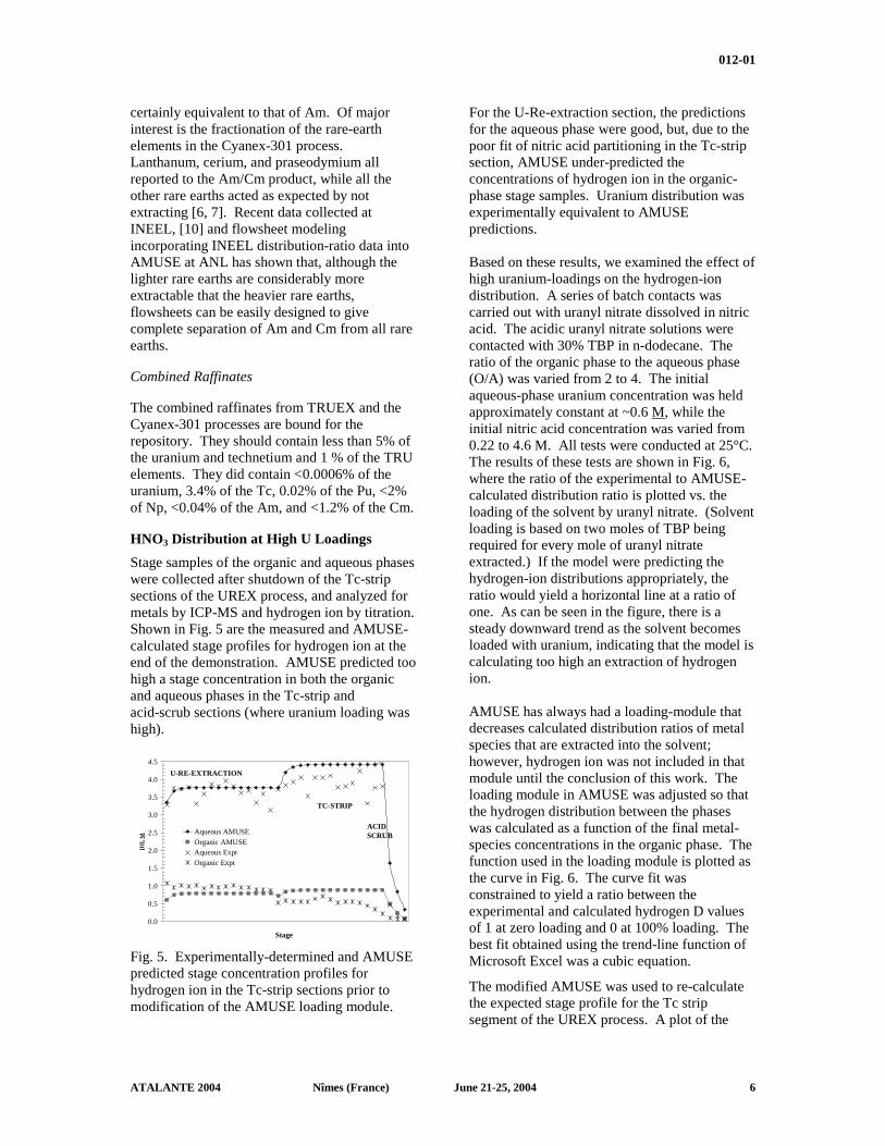
For the U-Re-extraction section, the predictions for the aqueous phase were good, but, due to the poor fit of nitric acid partitioning in the Tc-strip section, AMUSE under-predicted the concentrations of hydrogen ion in the organic-phase stage samples. Uranium distribution was experimentally equivalent to AMUSE predictions. Based on these results, we examined the effect of high uranium-loadings on the hydrogen-ion distribution. A series of batch contacts was carried out with uranyl nitrate dissolved in nitric acid. The acidic uranyl nitrate solutions were contacted with 30% TBP in n-dodecane. The ratio of the organic phase to the aqueous phase (O/A) was varied from 2 to 4. The initial aqueous-phase uranium concentration was held approximately constant at ~0.6 M, while the initial nitric acid concentration was varied from 0.22 to 4.6 M. All tests were conducted at 25°C. The results of these tests are shown in Fig. 6, where the ratio of the experimental to AMUSE-calculated distribution ratio is plotted vs. the loading of the solvent by uranyl nitrate. (Solvent loading is based on two moles of TBP being required for every mole of uranyl nitrate extracted.) If the model were predicting the hydrogen-ion distributions appropriately, the ratio would yield a horizontal line at a ratio of one. As can be seen in the figure, there is a steady downward trend as the solvent becomes loaded with uranium, indicating that the model is calculating too high an extraction of hydrogen ion. AMUSE has always had a loading-module that decreases calculated distribution ratios of metal species that are extracted into the solvent; however, hydrogen ion was not included in that module until the conclusion of this work. The loading module in AMUSE was adjusted so that the hydrogen distribution between the phases was calculated as a function of the final metal-species concentrations in the organic phase. The function used in the loading module is plotted as the curve in Fig. 6. The curve fit was constrained to yield a ratio between the experimental and calculated hydrogen D values of 1 at zero loading and 0 at 100% loading. The best fit obtained using the trend-line function of Microsoft Excel was a cubic equation.
The modified AMUSE was used to re-calculate the expected stage profile for the Tc strip segment of the UREX process. A plot of the
012-01
ATALANTE 2004 Nîmes (France) June 21-25, 2004 7
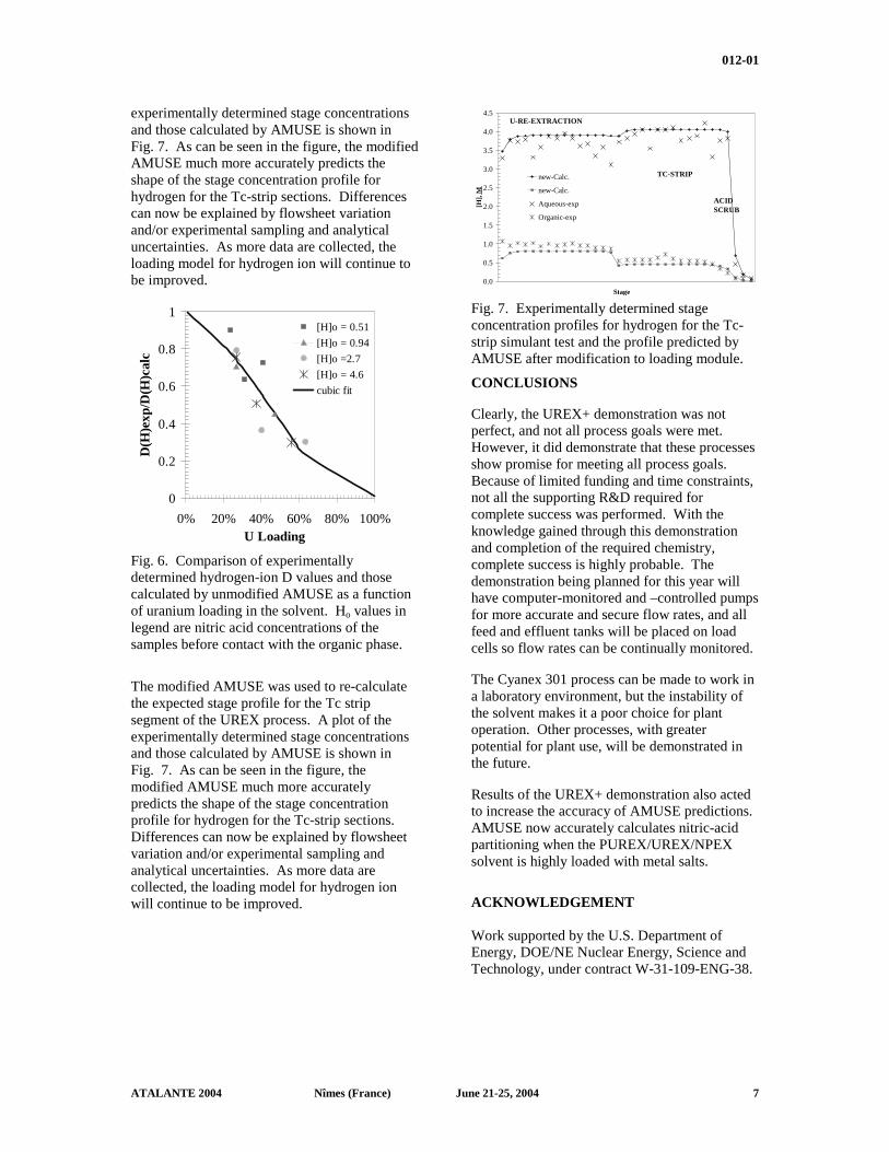
experimentally determined stage concentrations and those calculated by AMUSE is shown in Fig. 7. As can be seen in the figure, the modified AMUSE much more accurately predicts the shape of the stage concentration profile for hydrogen for the Tc-strip sections. Differences can now be explained by flowsheet variation and/or experimental sampling and analytical uncertainties. As more data are collected, the loading model for hydrogen ion will continue to be improved.
0
0.2
0.4
0.6
0.8
1
0% 20% 40% 60% 80% 100%U Loading
D(H
)exp
/D(H
)cal
c
[H]o = 0.51
[H]o = 0.94
[H]o =2.7
[H]o = 4.6
cubic fit
Fig. 6. Comparison of experimentally determined hydrogen-ion D values and those calculated by unmodified AMUSE as a function of uranium loading in the solvent. Ho values in legend are nitric acid concentrations of the samples before contact with the organic phase.
The modified AMUSE was used to re-calculate the expected stage profile for the Tc strip segment of the UREX process. A plot of the experimentally determined stage concentrations and those calculated by AMUSE is shown in Fig. 7. As can be seen in the figure, the modified AMUSE much more accurately predicts the shape of the stage concentration profile for hydrogen for the Tc-strip sections. Differences can now be explained by flowsheet variation and/or experimental sampling and analytical uncertainties. As more data are collected, the loading model for hydrogen ion will continue to be improved.
0.0
0.5
1.0
1.5
2.0
2.5
3.0
3.5
4.0
4.5
1 3 5 7 9 11 13 15 17 19 21 23 25 27 29 31 33Stage
[H],
M
new-Calc.
new-Calc.
Aqueous-exp
Organic-exp
U-RE-EXTRACTION
TC-STRIP
ACID SCRUB
Fig. 7. Experimentally determined stage concentration profiles for hydrogen for the Tc-strip simulant test and the profile predicted by AMUSE after modification to loading module.
CONCLUSIONS
Clearly, the UREX+ demonstration was not perfect, and not all process goals were met. However, it did demonstrate that these processes show promise for meeting all process goals. Because of limited funding and time constraints, not all the supporting R&D required for complete success was performed. With the knowledge gained through this demonstration and completion of the required chemistry, complete success is highly probable. The demonstration being planned for this year will have computer-monitored and –controlled pumps for more accurate and secure flow rates, and all feed and effluent tanks will be placed on load cells so flow rates can be continually monitored.
The Cyanex 301 process can be made to work in a laboratory environment, but the instability of the solvent makes it a poor choice for plant operation. Other processes, with greater potential for plant use, will be demonstrated in the future.
Results of the UREX+ demonstration also acted to increase the accuracy of AMUSE predictions. AMUSE now accurately calculates nitric-acid partitioning when the PUREX/UREX/NPEX solvent is highly loaded with metal salts.
ACKNOWLEDGEMENT Work supported by the U.S. Department of Energy, DOE/NE Nuclear Energy, Science and Technology, under contract W-31-109-ENG-38.
012-01
ATALANTE 2004 Nîmes (France) June 21-25, 2004 8
REFERENCES
1. J. J. Laidler and J. C. Bresee, “The Advanced Fuel Cycle Initiative of the U.S. Department of Energy: Development of Separations Technologies,” Proceedings of WM-04, Tucson, AZ February-March, 2004.
2. S. Aase, A. Bakel et al., “Demonstration of the UREX+ Process on Irradiated Nuclear Fuel,” 13th Annual Separations Science and Technology Conference, Gatlinburg, TN, October 2003.
3. G.F. Vandegrift, D. B. Chamberlain, C. Conner, J. M. Copple, J. A. Dow, L. Everson, J. C. Hutter, R. A. Leonard, L. Nuñez, M. C. Regalbuto, J. Sedlet, B. Srinivasan, S. Weber, and D. G. Wygmans, “Development and Demonstration of the TRUEX Solvent Extraction Process,” Proceedings of WM-93, Vol. 2, 1045.
4. G. F. Vandegrift and M. C. Regalbuto, “Validation of the Generic TRUEX Model Using Data from TRUEX Demonstrations with Actual High-Level Waste,” Proceedings of the Fifth International Conference on Radioactive Waste Management and Environmental Remediation (ICEM’95) Vol. 1, Cross-Cutting Issues and Management of High-Level Waste and Spent Fuel, Berlin, Germany, September 3-7, 1995, 457.
5. J. D. Law, R. S. Herbst, D. R. Peterman, R. D. Tillotson, and T. A. Todd, “Development of a Cobalt Dicarbollide/Polyethylene Glycol Solvent Extraction Process for Separation of Cesium and Strontium to Support Advanced Aqueous Reprocessing,” Proceedings of GLOBAL 2003, New Orleans, LA, November 2003.
6. G. Modolo and R. Odoj, “Influence of the Purity and Irradiation Stability of Cyanex 301 on the Separation of trivalent Actinides from Lanthanides by Solvent Extraction,” J. Rad. Nucl. Chem., vol 228 (1998), 83.
7. C. Hill, C. Madic, P. Baron, M. Ozowa, and Y. Tanaka, “Trivalent Minor Actinide/Lanthanide Separations, Using Organophosphinic Acids, J. Alloys and .Compounds, vol. 271-23 (1998), 159.
8. G. F. Vandegrift et al., “Lab-Scale Demonstration of the UREX+ Process,” Proceedings of WM-04, Tucson, AZ February-March, 2004.
9. M. C. Thompson, M. A. Norato, G. F. Kessinger, R. A. Pierce, T. S. Rudisill, and J. D. Johnson, “Demonstration of the UREX Solvent Extraction Process with Dresden Reactor Fuel Solution,” WSRC-TR-2002-00444, Revision0, September 30, 2002.
10. Private communication with J. D. Law, INEEL.