Embed Size (px)
Citation preview

Designing an Induction Cooker Using the S08PT Family by: Leo Pan, Dennis Lui, T.C. Lun
1 Introduction This application note describes how to use the Freescale PT60 8-bit MCU to develop a complete induction cooker as a quick start reference design for customers.
This application is an implementation example of System Design Guideline for 5V 8-bit families in Home Appliance Applications (AN4476) and How To Develop a Robust Software in Noise Environment (AN4463).
Contents 1 Introduction ............................................... 1 2 System Overview ....................................... 2 3 Hardware Design ....................................... 5 4 Firmware Design ..................................... 11 5 Conclusion ............................................... 17 6 References ............................................... 17 Appendix A Control Board Schematic ...... 18 Appendix B Power Board Schematic ........ 19
Freescale Semiconductor, Inc. Document Number: AN5030
Application Note Rev. 0 11/2014
© Freescale Semiconductor, Inc., 2014. All rights reserved. ___________________________________________________________________
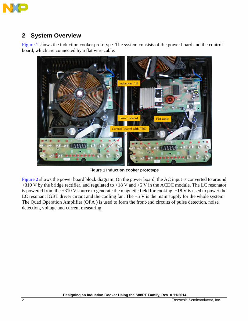
2 System Overview Figure 1 shows the induction cooker prototype. The system consists of the power board and the control board, which are connected by a flat wire cable.
Figure 1 Induction cooker prototype
Figure 2 shows the power board block diagram. On the power board, the AC input is converted to around +310 V by the bridge rectifier, and regulated to +18 V and +5 V in the ACDC module. The LC resonator is powered from the +310 V source to generate the magnetic field for cooking. +18 V is used to power the LC resonant IGBT driver circuit and the cooling fan. The +5 V is the main supply for the whole system. The Quad Operation Amplifier (OPA ) is used to form the front-end circuits of pulse detection, noise detection, voltage and current measuring.
Designing an Induction Cooker Using the S08PT Family, Rev. 0 11/2014 2 Freescale Semiconductor, Inc.
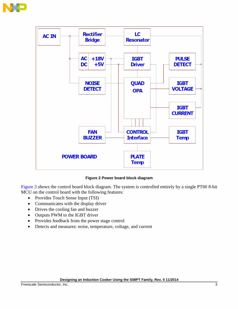
Figure 2 Power board block diagram
Figure 3 shows the control board block diagram. The system is controlled entirely by a single PT60 8-bit MCU on the control board with the following features:
• Provides Touch Sense Input (TSI) • Communicates with the display driver • Drives the cooling fan and buzzer • Outputs PWM to the IGBT driver • Provides feedback from the power stage control • Detects and measures: noise, temperature, voltage, and current
Designing an Induction Cooker Using the S08PT Family, Rev. 0 11/2014 Freescale Semiconductor, Inc. 3

Figure 3 Control board block diagram
Designing an Induction Cooker Using the S08PT Family, Rev. 0 11/2014 4 Freescale Semiconductor, Inc.

3 Hardware Design The pin assignment of the PT60 MCU is designed to be compatible with the 64-pin LQFP and the 44-pin LQFP, and it is also compatible to be migrated to the Kinetis E series MCUs. The following subsections provide detailed descriptions for each circuit portion. Refer to Figure 17 and Figure 18 for the reference symbols.
3.1 LED driver The LED driver circuitry is shown in Figure 4. A traditional 4-digit 7-segment LED module is used to display the cooking time and error information. Additionally, 22 LED indicators composed of 3-digit 8-segments are used to indicate the cooker's operation mode and operation levels. The 4-digit 7-segment LED module and the 22 LED indicators are driven by an LED driver – TM1668, which is controlled by the MCU through three GPIOs. The display content will be updated and refreshed into the TM1668 LED driver instantly by the MCU through the 3-wire interface. According to AN4476, RC filters are added on the 3-wire interface and placed closely to TM1688 on the PCB to improve the EMC performance.
Figure 4 LED driver circuit
3.2 Touch Sense Input (TSI) The Touch Sense Input circuitry is shown in Figure 5 and the Touch Sense Input PCB layout is shown in Figure 6. To improve the EMC performance, 5 pF capacitors are added on touch sense inputs and placed closely to the touch pads on the PCB, 470 Ω resistors are added on the touch sense input paths in series and placed closely to the corresponding MCU TSI input pins on the PCB, and dedicated GND shielding for all the TSI routing traces is also added.
Designing an Induction Cooker Using the S08PT Family, Rev. 0 11/2014 Freescale Semiconductor, Inc. 5

Figure 5 Touch Sense Input circuitry
Figure 6 Touch Sense Input PCB layout
Designing an Induction Cooker Using the S08PT Family, Rev. 0 11/2014 6 Freescale Semiconductor, Inc.
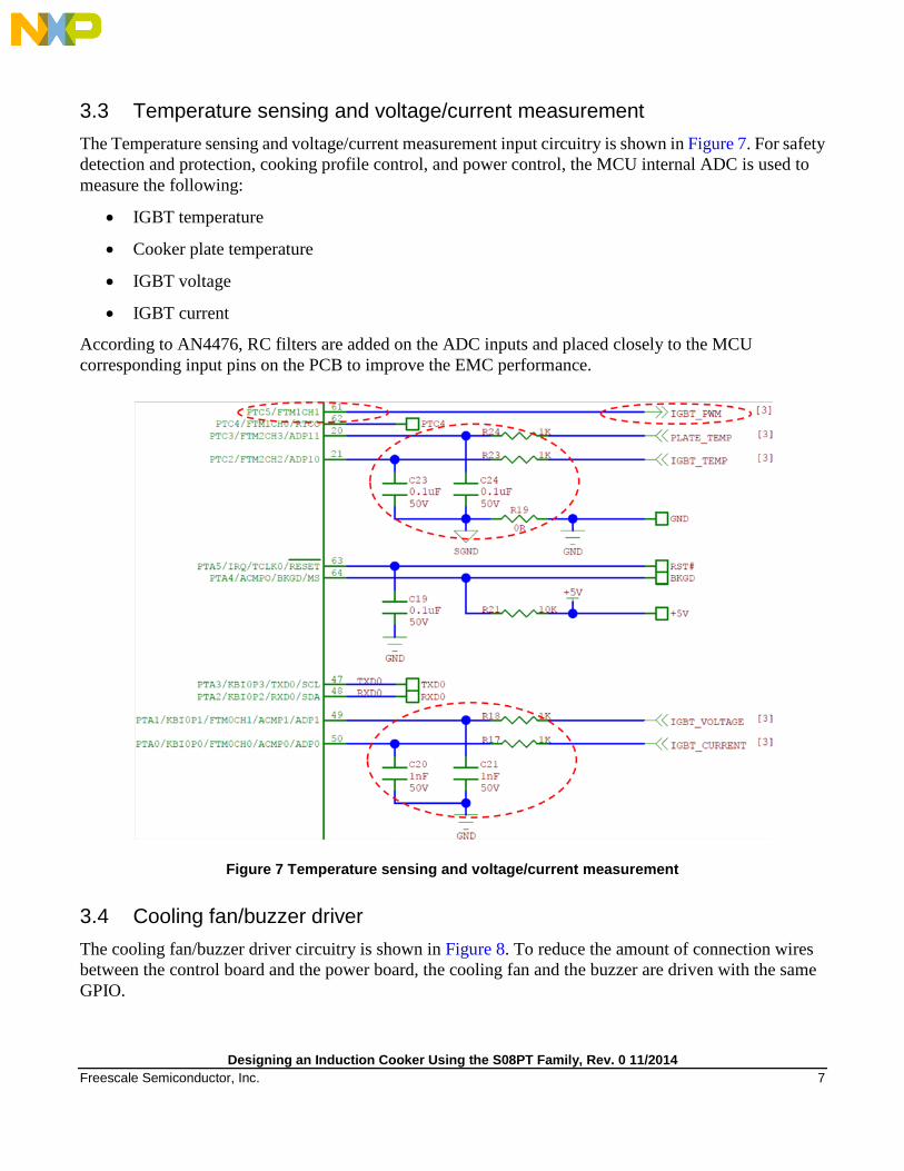
3.3 Temperature sensing and voltage/current measurement The Temperature sensing and voltage/current measurement input circuitry is shown in Figure 7. For safety detection and protection, cooking profile control, and power control, the MCU internal ADC is used to measure the following:
• IGBT temperature
• Cooker plate temperature
• IGBT voltage
• IGBT current
According to AN4476, RC filters are added on the ADC inputs and placed closely to the MCU corresponding input pins on the PCB to improve the EMC performance.
Figure 7 Temperature sensing and voltage/current measurement
3.4 Cooling fan/buzzer driver The cooling fan/buzzer driver circuitry is shown in Figure 8. To reduce the amount of connection wires between the control board and the power board, the cooling fan and the buzzer are driven with the same GPIO.
Designing an Induction Cooker Using the S08PT Family, Rev. 0 11/2014 Freescale Semiconductor, Inc. 7

Figure 8 Temperature sensing and voltage/current measurement
3.5 Noise detection The noise detection circuitry is shown in Figure 9. When high frequency or high voltage noise is present on the AC input, the comparator output will be low on NOISE_DET. NOISE_DET is logical AND with IGBT_PWM to stop the IGBT driver from exciting the LC resonator when noise is detected. In the meantime, NOISE_DET is sent to KBI input to generate an interrupt for further noise detection handling. According to AN4476, the RC filter is added on the KBI input and placed closely to the MCU corresponding input pin on the PCB to improve the EMC performance.
Figure 9 Noise detection
Designing an Induction Cooker Using the S08PT Family, Rev. 0 11/2014 8 Freescale Semiconductor, Inc.

Figure 10 LC Resonator, IGBT PWM driver, and pulse detection
3.6 Pulse detection The pulse detection circuitry is shown in Figure 10. When the LC resonator is excited by the IGBT, the IGBT Vce voltage is differentiated from the +310 V power input so that the comparator outputs pulses on PULSE_DET. PULSE_DET is connected to the MCU FTM2 input for valid cookware detection and IGBT PWM parameter configuration. According to AN4476, the RC filter is added on the FTM2 input and placed closely to the MCU corresponding input pin on the PCB to improve the EMC performance, as shown in Figure 4.
3.7 IGBT PWM driver The IGBT PWM driver circuitry is shown in Figure 10. The IGBT_PWM signal is output from FTM1CH1, as shown in Figure 7, and it is logical AND with NOISE_DET for noise protection, as shown in Figure 10. The Totem pole circuit converts the PWM signal from 5 V to 18 V so that the IGBT can be driven properly.
3.8 LC resonator A typical LC Resonant circuit is shown in Figure 10. The LC Resonant equivalent circuit and its waveform are shown in Figure 11. As shown, the induction coil and the cookware form the resonant Lr, so Lr is a variable when a different cookware is used in cooking. Proper Lr and Cr should be selected so that the LC resonant frequency (f0 = 1/2π√LrCr) is higher than 20 KHz to avoid audio frequency.
Designing an Induction Cooker Using the S08PT Family, Rev. 0 11/2014 Freescale Semiconductor, Inc. 9

Figure 11 LC resonant equivalent circuit and its waveform
Designing an Induction Cooker Using the S08PT Family, Rev. 0 11/2014 10 Freescale Semiconductor, Inc.
4 Firmware Design Proper firmware design enables a cost effective system and improves the overall system performance. The following subsections provide the detailed descriptions for an effective firmware design.
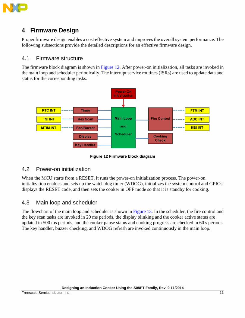
4.1 Firmware structure The firmware block diagram is shown in Figure 12. After power-on initialization, all tasks are invoked in the main loop and scheduler periodically. The interrupt service routines (ISRs) are used to update data and status for the corresponding tasks.
Figure 12 Firmware block diagram
4.2 Power-on initialization When the MCU starts from a RESET, it runs the power-on initialization process. The power-on initialization enables and sets up the watch dog timer (WDOG), initializes the system control and GPIOs, displays the RESET code, and then sets the cooker in OFF mode so that it is standby for cooking.
4.3 Main loop and scheduler The flowchart of the main loop and scheduler is shown in Figure 13. In the scheduler, the fire control and the key scan tasks are invoked in 20 ms periods, the display blinking and the cooker active status are updated in 500 ms periods, and the cooker pause status and cooking progress are checked in 60 s periods. The key handler, buzzer checking, and WDOG refresh are invoked continuously in the main loop.
Designing an Induction Cooker Using the S08PT Family, Rev. 0 11/2014 Freescale Semiconductor, Inc. 11

Figure 13 Main loop and scheduler flowchart
4.4 Timer Software timers are used for the scheduler, buzzer beep time counting, task delay, and so on. The RTC ISR updates these timers in a 1 ms period.
4.5 Key handler The key handler is invoked continuously in the main loop to check if any key code is pushed into the key buffer by the key scan task. If a valid command is confirmed, it invokes the corresponding task to take action for cooking.
4.6 Fan/buzzer The buzzer is enabled in different tasks for notice and warning purposes when necessary. When the buzzer is enabled, MTIM ISR is used to toggle the buzzer driven by the GPIO output in a preset frequency. The cooling fan is driven with the same GPIO as the buzzer to reduce the amount of connection wires between the control board and the power board. Therefore, the fan driver status must be restored when the buzzer is off.
Designing an Induction Cooker Using the S08PT Family, Rev. 0 11/2014 12 Freescale Semiconductor, Inc.

4.7 Display The display buffer is updated and refreshed into the display driver instantly during the different application tasks. The display blinking status is updated in a 500 ms period. Some error codes are defined as shown in Table 1.
Table 1 Display error code definition
Error Code Description Error Code Description
E001 External reset E100 AC Input Noise Detected
E002 WDOG reset E101 AC Input Undervoltage
E003 Illegal Opcode reset E102 AC Input Overvoltage
E004 Illegal Address reset E104 IGBT Over Temperature
E005 ICS module reset E108 Plate Over Temperature
E006 Low Voltage Detect reset E110 IGBT Over Current
E021 No cookware error
E022 No echo pulse error
4.8 Key scan The key scan task is invoked in a 20 ms period. It analyzes key scan data that are updated by the TSI ISR and pushes the corresponding key code into the key buffer when the pads touch occurs. As shown in Figure 15, heavy noise is generated during cookware detection and IGBT driver ramp-up, because the Cr in the LC resonator is discharged within a short time through the IGBT. To prevent the TSI from capturing the wrong data that are caused by these heavy noises, the key scan task must not be invoked during this stage.
4.9 Fire control The fire control task is invoked in a 20 ms period before the Key Scan task begins. All power control activities are completed during the fire control task. Prior to starting the cooker, the fire control task performs the following:
• Measures the AC input voltage to check whether undervoltage or overvoltage occurs. • Monitors the noise detection output to check whether any high frequency or high voltage noise
presents on the AC input. • Senses the IGBT and the cooker plate temperature to determine whether it is safe to cook.
When all fire control tasks are complete and pass, it then performs cookware detection: • Confirms IGBT driver PWM parameter settings. • Begins IGBT driver ramp-up. • Implements over-driving and cookware removed detection when cooking is in progress.
Designing an Induction Cooker Using the S08PT Family, Rev. 0 11/2014 Freescale Semiconductor, Inc. 13

As described in Section 4.8 “Key scan”, heavy noise occurs during cookware detection and IGBT driver ramp-up. To prevent the TSI from capturing the wrong data, the fire control will not begin cookware detection and IGBT driver ramp-up if TSI scanning is in progress.
4.9.1 Cookware detection All induction heating (IH ) applied systems are developed by using electromagnetic induction, and thus ferromagnetic metal such as cast iron or stainless steel cookware must be used for an induction cooker. For safety purposes, a reasonable size of cookware must also be used. For example, the cooker must not start if a small stainless steel spoon is placed on the plate. Therefore, valid cookware detection is very important. As shown in Figure 14, the pulses count output from PULSE_DET shown in Figure 10 is changed when a different cookware is placed on top of the cooker plate. This feature can be used for valid cookware detection.
Figure 14 Cookware detection
4.9.2 IGBT driver PWM parameter setting As shown in Figure 15, the first pulse width that can be captured by the MCU FTM2 in cookware detection is around half of the LC resonant period (T0 = 2π√LrCr). With this captured pulse width, the IGBT driver PWM parameter can be set accordingly to match different cookware used. To prevent overvoltage on IGBT Vce, the maximum IGBT driver PWM pulse width is set to 1.5 times of T0/2.
Designing an Induction Cooker Using the S08PT Family, Rev. 0 11/2014 14 Freescale Semiconductor, Inc.
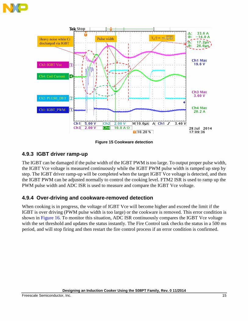
Figure 15 Cookware detection
4.9.3 IGBT driver ramp-up The IGBT can be damaged if the pulse width of the IGBT PWM is too large. To output proper pulse width, the IGBT Vce voltage is measured continuously while the IGBT PWM pulse width is ramped up step by step. The IGBT driver ramp-up will be completed when the target IGBT Vce voltage is detected, and then the IGBT PWM can be adjusted normally to control the cooking level. FTM2 ISR is used to ramp up the PWM pulse width and ADC ISR is used to measure and compare the IGBT Vce voltage.
4.9.4 Over-driving and cookware-removed detection When cooking is in progress, the voltage of IGBT Vce will become higher and exceed the limit if the IGBT is over driving (PWM pulse width is too large) or the cookware is removed. This error condition is shown in Figure 16. To monitor this situation, ADC ISR continuously compares the IGBT Vce voltage with the set threshold and updates the status instantly. The Fire Control task checks the status in a 500 ms period, and will stop firing and then restart the fire control process if an error condition is confirmed.
Designing an Induction Cooker Using the S08PT Family, Rev. 0 11/2014 Freescale Semiconductor, Inc. 15

Figure 16 Over driving and cookware removed detection
4.10 Cooking check The cooking check task is invoked in a 60 second period. The IGBT temperature and the cooker plate temperature are monitored for safety control, and the plate temperature and cooking timer are updated for cooking profile control.
Designing an Induction Cooker Using the S08PT Family, Rev. 0 11/2014 16 Freescale Semiconductor, Inc.

5 Conclusion A complete induction cooker reference design is illustrated as a cost effective and high EMC performance example to enable customers to adapt the Freescale PT60, 8-bit microcontroller solution into their products quickly.
6 References Additional documentation that may be useful includes the following and are available at freescale.com.
• Design Mircowave Oven Using S08PT Family (document AN4596)
• EMC Design Considerations for MC9S08PT60 (document AN4438)
• System Design Guideline for 5V 8-bit families in Home Appliance Applications (document AN4476)
• How To Develop a Robust Software in Noise Environment (document AN4463)
• Designing for Board Level Electromagnetic Compatibility (document AN2321)
• Improving the Transient Immunity Performance of Microcontroller-Based Applications (document AN2764)
Designing an Induction Cooker Using the S08PT Family, Rev. 0 11/2014 Freescale Semiconductor, Inc. 17

Appendix A Control Board Schematic Figure 17 shows the details of the PT60 control board connections.
Figure 17 Control board schematic
Designing an Induction Cooker Using the S08PT Family, Rev. 0 11/2014 18 Freescale Semiconductor, Inc.

Appendix B Power Board Schematic Figure 18 shows the details of the PT60 power board connections.
Figure 18 Power board schematic
Designing an Induction Cooker Using the S08PT Family, Rev. 0 11/2014 Freescale Semiconductor, Inc. 19

How to Reach Us:
Home Page: freescale.com
Web Support: freescale.com/support
Information in this document is provided solely to enable system and software implementers to use Freescale products. There are no express or implied copyright licenses granted hereunder to design or fabricate any integrated circuits based on the information in this document.
Freescale reserves the right to make changes without further notice to any products herein. Freescale makes no warranty, representation, or guarantee regarding the suitability of its products for any particular purpose, nor does Freescale assume any liability arising out of the application or use of any product or circuit, and specifically disclaims any and all liability, including without limitation consequential or incidental damages. “Typical” parameters that may be provided in Freescale data sheets and/or specifications can and do vary in different applications, and actual performance may vary over time. All operating parameters, including “typicals,” must be validated for each customer application by customer’s technical experts. Freescale does not convey any license under its patent rights nor the rights of others. Freescale sells products pursuant to standard terms and conditions of sale, which can be found at the following address: freescale.com/SalesTermsandConditions.
Freescale, the Freescale logo, and Kinetis are trademarks of Freescale Semiconductor, Inc., Reg. U.S. Pat. & Tm. Off. All other product or service names are the property of their respective owners. © 2014 Freescale Semiconductor, Inc.
Document Number: AN5030 Rev. 0 11/2014