Embed Size (px)
Citation preview
Next, we must teach the loop, nodal and modified nodal analysis. And we have to teach all of this. in order to explain that anywhere the loop or nodal methods are applicable, we shall prefer them, as giving less equations (i.e. being computationally less expensive) than the general modified nodal analysis. And we have to teach them in a matrix topological way, to allow students the possibility of writing simple programs for solving different circuits. I found it too difficult to teach such material using the dynamic circuit as example: the reactive ele- ments with their Laplace impedance and ad- mittance. the sources due to the initial conditions expressed in the s-domain, the Laplace equations of the inductive coupling, are all a too heavy burden for a beginner. So, I prefer to give the student the possibility of mastering the analysis methodology by apply- ing it fint to very simple circuits: networks containing only DC sources andone-portresis- tors. The txtension to resistive circuits contain- ing controlled sources will not be too difficult. Simple exercises containing equivalent resis- tance computation, basic circuit theorems etc. can be left as homework problems.
Students are now prepared to be intro- duced to general dynamic circuit analysis. Again, any method will be first taught for circuits containing only independent sour- ces and two-terminal resistors, inductors, capacitors, coupling being introduced in the next phase. The sinusoidal steady state will become a simple particular case of the dynamic analysis, by requiring a little lec- ture time. Now is the time for introducing market available circuit analysis programs (includrd the beloved SPICE), but also the symbolic computation programs which are gaining more and more importance. State equations, transfer functions, with their zeros and poles, impulse and step response, frequency response are the next topics.
By this time, with all the fundamental and compulsory circuit theory subjects be- hind us. if time allows. we can introduce an advanced subject taught at the undergradu- ate level. The choice can be among time- variable networks, sensitivities and optimization, switched-capacitor circuits, etc.. using computer-aided methods. And after texhing all these subjects and passing the exam (by the students and .... the lec- turer). we can breathe freely: we taught cir- cuits SERIOUSLY. CD Reference
1. R.A. Rohrer. “Taking Circuits Seriously,”
40
DESIGNER’S CASEBOOK
A Simple One-Shot Multivibrator capacitor Cz (the exact figure depends on the leakage currents of D2 and D3).
I. M. Filanovsky Thecircuitistriggeredbythepush-button Universiw of Alberta switch S. Depressing S discharges C2via Rh, Edmonton, Alberta, Canada and creates a short positive spike at the base
of Qz (the base potential momentarily raises to 2Vcc - 0.7V). Then Q2 Will be off and, as T he ubiquitous 555 timer is fquently a result, Q1 and Q3 will be off also. As soon as Q3 is off the transistor Q4 will be on, and the output voltage drops to vo = V ~ L = Vcc - [(RI I/R7xVRef - 0.7V)I. The circuit is in its
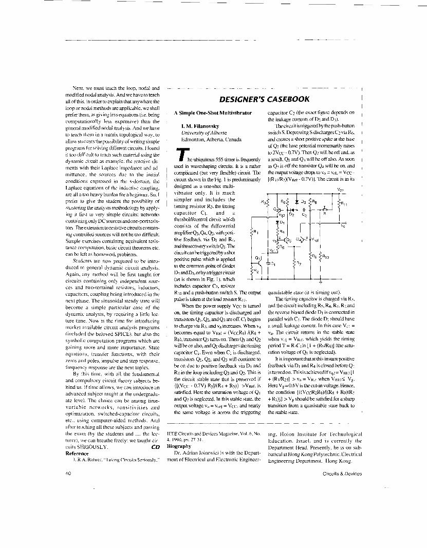
used in waveshaping circuits. It is a rather complicated (but very flexible) circuit. The ckuit shown in the Fig. 1 is predominantly designed as a one-shot multi- vibrator only. It is much simpler and includes the timing resistor R3, the timing capacitor C1, and a thresholdcontrol circuit which consists of the differential amplifier Q,Q4, Q2, with posi- tive feedback via D1 and h, andtherecoveryswitchQl. The circuit can be triggered by a shot positive pulse which is applied to the common point of diodes Dz and&, orby atrigger circuit
vcc
(as is shown in Fig. l), which includes capacitor C2, resistor Rio and a push-button switch S. The output pulse is taken at the load resistor RI I .
When the power supply Vcc is tumed on, the timing capacitor is discharged and transistors Qi, 42, and Q3 are off. CI begins to charge via R3, and va increases. When va
R9), transistor 4 3 tums on. Then QI and 4 2 will beon also, andQl discharges the timing capacitor CI . Even when Ci is discharged, transistors Qi, 42 , and Q3 will continue to be on due to positive feedback via Di and R4 in the loop including 4 3 and Q2. This is the circuit stable state that is preserved if { [(VCC - 0 . W Rsl/(h + R5)) >vRef, is satisfied. Here the saturation voltage of Qi and Q2 is neglected. In this stable state, the output voltage vo = V ~ H = Vcc, and nearly the same voltage is across the triggering
becomes equal to VRef = (VCCR~) /(R8 +
I 1 I + quasistable state (it is timing out).
The timing capacitor is charged via R3, and the circuit including Rs, a, R I , R2 and the reverse biased diode D1 is connected in parallel with CJ. The diode Di should have a small leakage current. In this case VCi = va. The circuit retums in the stable state when vci = VRef, which yields the timing period T = R3C I In [ 1 + (RdRx)] (the satu- ration voltage of Qi is neglected).
It is important that at this instant positive feedback via D1 and & is closed before QI is tumedon. Thisisachievedif V@=VBEI [ 1
HereV, =0.6V is the cut-in voltage. Hence, the condition { ((VCCR~R~)/[(RX + R9)(R1 + R2)]) > V, should be satisfied for a sharp transition from a quasistable state back to the stable state.
1 1
1
+ (Rj/R2)] 2. va = VRer when VBEI< vg. I 1 1 I
-~
IEEE Circuits and Devices Magazine. Vol. 6. No. 4, 1990, pp. 27-3 1 . Biography
Dr. Adrian Ioinovici is with the Depart- ment of Electrical and Electronic Engineer-
ing, Holon Institute for Technological Education, Israel, and is currently the Department Head. Presently, he is on sab- batica] at H~~~ ~ ~ ~ ~ ~ ~ l ~ t ~ ~ h ~ i ~ . Electrical ~ ~ ~ i ~ ~ ~ - i ~ ~ Department, H~~~ K ~ ~ ~ .
Circuits & Devices


![waveform generator multivibrator [Read-Only]ggn.dronacharya.info/.../Vsem/waveform_generator_multivibrator.pdf · •Three type of Multivibrator:- Astable (free running), monostable](https://img.pdfslide.us/doc/110x75/5fc8515215411b379f4f5bb9/waveform-generator-multivibrator-read-onlyggn-athree-type-of-multivibrator-.jpg)