Embed Size (px)
Citation preview
Aussi disponible en français – CRT-43
TRC-43 Issue 3
November 2012
Spectrum Management and Telecommunications Telecommunications Regulation Circular
Designation of Emissions, Class of Station and Nature of Service

i
Preface Telecommunications Regulation Circulars (TRC) are issued as required to provide information to those engaged in telecommunications in Canada. In keeping with new developments, the content of these circulars is subject to change at any time. It is therefore suggested that interested persons consult the nearest district office of Industry Canada for additional details. While every reasonable effort has been made to ensure accuracy, no warranty is expressed or implied. As well, these circulars have no status in law. Comments and suggestions may be directed to the following address: Director General Engineering, Planning and Standards Branch Industry Canada 300 Slater Street, 19th Floor Ottawa, Ontario K1A 0C8 Email: [email protected] All Spectrum Management and Telecommunications publications are available on the following website: http://ic.gc.ca/spectrum.

ii
Contents
1. Introduction................................................................................................................................... 1
2. Definitions...................................................................................................................................... 1
3. Related Documents ....................................................................................................................... 1
4. Class of Station and Nature of Service Designators .................................................................. 2 4.1 Class of Station Designators ............................................................................................... 2 4.2 Nature of Service Designators ............................................................................................ 4
5. Designation of Emissions.............................................................................................................. 5
6. Designation of Necessary Bandwidth.......................................................................................... 5
7. Classification of Emissions ........................................................................................................... 5 7.1 First symbol—Type of modulation of the main carrier ...................................................... 6 7.2 Second symbol—Nature of signal(s) modulating the main carrier .................................... 7 7.3 Third symbol—Type of information to be transmitted....................................................... 7 7.4 Fourth symbol—Details of signal(s)................................................................................... 8 7.5 Fifth symbol—Nature of multiplexing ............................................................................... 9
8. Determination of Necessary Bandwidths.................................................................................... 9
9. Examples of Designation of Emissions...................................................................................... 11

Designation of Emissions, Class of Station and Nature of Service TRC-43
1
1. Introduction The purpose of this document is to outline designation of emissions, class of station and nature of service information used by Industry Canada for radio equipment certification purposes and for the issuance of licences to permit the operation of radio stations in Canada. Radio stations and their emissions are classified into various categories as detailed in this document. When applying for a licence to operate a radio station in accordance with the procedures established by Industry Canada, an applicant shall, to the extent possible, use the methods and symbols contained in this document. 2. Definitions The following definitions of operational terminology may assist in the designation of radio emissions. Necessary bandwidth: The width of the frequency band which is just sufficient to ensure the transmission of information at the rate and with the quality required under specified conditions for a given class of emission. Telegraphy: A form of telecommunication in which the transmitted information is intended to be recorded on arrival as a graphic document;1 the transmitted information may sometimes be presented in an alternative form or may be stored for subsequent use. Telecommand: The use of telecommunication for the transmission of signals to initiate, modify or terminate functions of equipment at a distance. Telemetry: The use of telecommunication for automatically indicating or recording measurements at a distance from the measuring instrument. Telephony: A form of telecommunication primarily intended for the exchange of information in the form of speech. 3. Related Documents The following International Telecommunication Union (ITU) spectrum management document should be consulted: Recommendation ITU-R SM.1138: Determination of necessary bandwidths including examples for their calculation and associated examples for the designation of emission.
1 A graphic document records information in a permanent form and is capable of being filed and consulted; it may take the
form of written or printed matter or the form of a fixed image.
Designation of Emissions, Class of Station and Nature of Service TRC-43
2
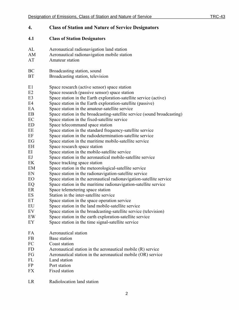
4. Class of Station and Nature of Service Designators 4.1 Class of Station Designators AL Aeronautical radionavigation land station AM Aeronautical radionavigation mobile station AT Amateur station BC Broadcasting station, sound BT Broadcasting station, television E1 Space research (active sensor) space station E2 Space research (passive sensor) space station E3 Space station in the Earth exploration-satellite service (active) E4 Space station in the Earth exploration-satellite (passive) EA Space station in the amateur-satellite service EB Space station in the broadcasting-satellite service (sound broadcasting) EC Space station in the fixed-satellite service ED Space telecommand space station EE Space station in the standard frequency-satellite service EF Space station in the radiodetermination-satellite service EG Space station in the maritime mobile-satellite service EH Space research space station EI Space station in the mobile-satellite service EJ Space station in the aeronautical mobile-satellite service EK Space tracking space station EM Space station in the meteorological-satellite service EN Space station in the radionavigation-satellite service EO Space station in the aeronautical radionavigation-satellite service EQ Space station in the maritime radionavigation-satellite service ER Space telemetering space station ES Station in the inter-satellite service ET Space station in the space operation service EU Space station in the land mobile-satellite service EV Space station in the broadcasting-satellite service (television) EW Space station in the earth exploration-satellite service EY Space station in the time signal-satellite service FA Aeronautical station FB Base station FC Coast station FD Aeronautical station in the aeronautical mobile (R) service FG Aeronautical station in the aeronautical mobile (OR) service FL Land station FP Port station FX Fixed station LR Radiolocation land station

Designation of Emissions, Class of Station and Nature of Service TRC-43
3
MA Aircraft station ML Land mobile station MO Mobile station MR Radiolocation mobile station MS Ship station NL Maritime radionavigation land station NR Radionavigation mobile station OD Oceanographic data station OE Oceanographic data interrogating station PL Combination of two or more classes of station (limited to collective entries made under the
terms of the ITU’s Radio Regulations, Article 20.5) RA Radio astronomy station RM Maritime radionavigation mobile station RN Radionavigation land station SA Meteorological aids mobile station SM Meteorological aids base station SS Standard frequency and time signal station TA Earth station in the amateur-satellite service TB Aeronautical earth station TC Earth station in the fixed-satellite service TD Space telecommand earth station TE Satellite EPIRB in the mobile-satellite service TF Fixed earth station in the radiodetermination-satellite service TG Ship earth station TH Earth station in the space research service TI Coast earth station TJ Aircraft earth station TK Space tracking earth station TL Mobile earth station in the radiodetermination-satellite service TM Earth station in the meteorological-satellite service TN Fixed earth station in the radionavigation-satellite service TO Mobile earth station in the aeronautical radionavigation-satellite service TQ Mobile earth station in the maritime radionavigation-satellite service TR Space telemetering earth station TT Earth station in the space operation service TU Land mobile earth station TW Earth station in the earth exploration-satellite service TX Fixed earth station in the maritime radionavigation-satellite service TY Base earth station TZ Fixed earth station in the aeronautical radionavigation-satellite service

Designation of Emissions, Class of Station and Nature of Service TRC-43
4
UA Mobile earth station UB Earth station in the broadcasting-satellite service (sound broadcasting) UD Space telecommand mobile earth station UE Earth station in the standard frequency-satellite service UH Mobile earth station in the space research service UK Space tracking mobile earth station UM Mobile earth station in the meteorological-satellite service UN Mobile earth station in the radionavigation-satellite service UR Space telemetering mobile earth station UT Mobile earth station in the space operation service UV Earth station in the broadcasting-satellite service (television) UW Mobile earth station in the earth-exploration-satellite service UY Earth station in the time signal-satellite service VA Land earth station 4.2 Nature of Service Designators AS2 Stations using adaptive system AX Fixed station used for provision of services related to aircraft flight safety CO Station open to official correspondence exclusively CP3 Station open to public correspondence CR Station open to limited correspondence CV Station open exclusively to correspondence of a private agency FS Land station established solely for the safety of life HP4 Fixed station using high altitude platform MX Fixed station used for transmission of meteorological information OT Station open exclusively to operational traffic of the service concerned PX Fixed station used for press transmission RC Non-directional radiobeacon RD Directional radiobeacon RG Radio direction-finding station RT Revolving radiobeacon
2 Adaptive System: A radiocommunication system which varies its radio characteristics according to channel quality.
(ref. the ITU’s Radio Regulations No. 1.109A) 3 Public correspondence: Any telecommunication which the offices and stations must, by reason of their being at the
disposal of the public, accept for transmission (CS). (ref. the ITU’s Radio Regulations No. 1.116) 4 High altitude platform station: A station located on an object at an altitude of 20-50 km and at a specified, nominal, fixed
point relative to the Earth. (ref. the ITU’s Radio Regulations No. 1.66A)

Designation of Emissions, Class of Station and Nature of Service TRC-43
5
ST5 Fixed station using tropospheric scatter 5. Designation of Emissions Emissions are designated according to their necessary bandwidth and their classification. The first four characters of the designation of an emission describe the necessary bandwidth. These four characters are followed by three to five additional characters which describe the classification. Examples of emissions designators are provided in Section 9. 6. Designation of Necessary Bandwidth The necessary bandwidth, as determined in accordance with the formulas and examples given in this TRC, are expressed by three numerals and one letter. The letter occupies the position of the decimal point and represents the unit of bandwidth. The first character shall not be zero or K, M, or G. Necessary bandwidths shall be designated as shown below: between 0.001 and 999 Hz shall be expressed in Hz (letter H); between 1.00 and 999 kHz shall be expressed in kHz (letter K); between 1.00 and 999 MHz shall be expressed in MHz (letter M); and between 1.00 and 999 GHz shall be expressed in GHz (letter G). Examples of designated necessary bandwidths would be:
0.002 Hz = H002 0.1 Hz = H100 25.3Hz = 25H3 400 Hz = 400H 2.4 kHz = 2K40
6 kHz = 6K00 12.5 kHz = 12K5 180.4 kHz = 180K 180.5 kHz = 181K 180.7 kHz = 181K
1.25 MHz = 1M25 2 MHz = 2M00 10 MHz = 10M0 202 MHz = 202M 5.65 GHz = 5G65
7. Classification of Emissions A minimum of three symbols are used to describe the basic characteristics of radio waves: 1. The first symbol—Type of modulation of the main carrier 2. The second symbol—Nature of the signal(s) modulating the main carrier 3. The third symbol—Type of information being transmitted
5 Tropospheric scatter: The propagation of radio waves by scattering as a result of irregularities or discontinuities in the
physical properties of the troposphere. (ref. the ITU’s Radio Regulations No. 1.164)
Designation of Emissions, Class of Station and Nature of Service TRC-43
6
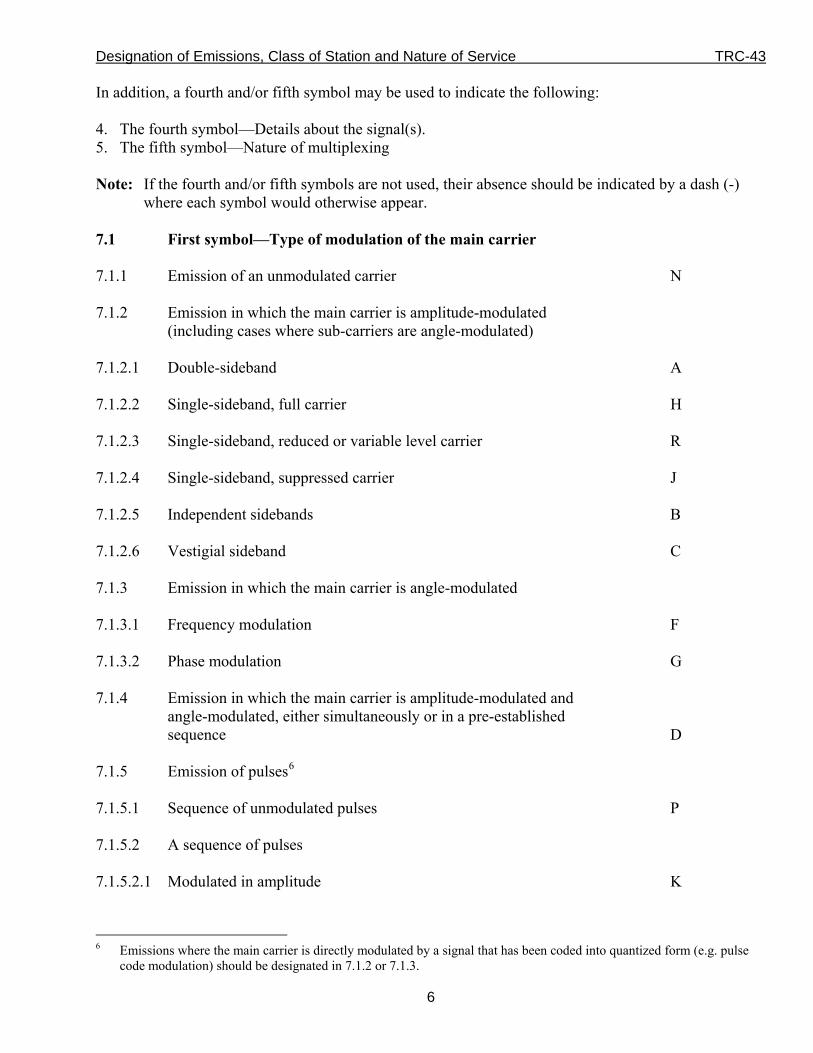
In addition, a fourth and/or fifth symbol may be used to indicate the following: 4. The fourth symbol—Details about the signal(s). 5. The fifth symbol—Nature of multiplexing Note: If the fourth and/or fifth symbols are not used, their absence should be indicated by a dash (-)
where each symbol would otherwise appear. 7.1 First symbol—Type of modulation of the main carrier 7.1.1 Emission of an unmodulated carrier N 7.1.2 Emission in which the main carrier is amplitude-modulated (including cases where sub-carriers are angle-modulated) 7.1.2.1 Double-sideband A 7.1.2.2 Single-sideband, full carrier H 7.1.2.3 Single-sideband, reduced or variable level carrier R 7.1.2.4 Single-sideband, suppressed carrier J 7.1.2.5 Independent sidebands B 7.1.2.6 Vestigial sideband C 7.1.3 Emission in which the main carrier is angle-modulated 7.1.3.1 Frequency modulation F 7.1.3.2 Phase modulation G 7.1.4 Emission in which the main carrier is amplitude-modulated and angle-modulated, either simultaneously or in a pre-established sequence D 7.1.5 Emission of pulses6 7.1.5.1 Sequence of unmodulated pulses P 7.1.5.2 A sequence of pulses 7.1.5.2.1 Modulated in amplitude K
6 Emissions where the main carrier is directly modulated by a signal that has been coded into quantized form (e.g. pulse
code modulation) should be designated in 7.1.2 or 7.1.3.

Designation of Emissions, Class of Station and Nature of Service TRC-43
7
7.1.5.2.2 Modulated in width/duration L 7.1.5.2.3 Modulated in position/phase M 7.1.5.2.4 In which the carrier is angle-modulated during the period of the pulse Q 7.1.5.2.5 Which is a combination of the foregoing or is produced by other means V 7.1.6 Cases (not covered above) in which an emission consists of the main carrier modulated, either simultaneously or in a pre-established sequence, in a combination of two or more of the following modes: amplitude, angle, and/or pulse W 7.1.7 Cases not otherwise covered X 7.2 Second symbol—Nature of signal(s) modulating the main carrier 7.2.1 No modulating signal 0 7.2.2 A single channel containing quantized or digital information without the use of a modulating sub-carrier7 1 7.2.3 A single channel containing quantized or digital information with the use of a modulating sub-carrier8 2
7.2.4 A single channel containing analog information 3 7.2.5 Two or more channels containing quantized or digital information 7 7.2.6 Two or more channels containing analog information 8 7.2.7 Composite system with one or more channels containing quantized or digital information, together with one or more channels containing analog information 9 7.2.8 Cases not otherwise covered X 7.3 Third symbol—Type of information to be transmitted9 7.3.1 No information transmitted N
7 Emissions where the main carrier is directly modulated by a signal that has been coded into quantized form (e.g. pulse
code modulation) should be designated in 7.1.2 or 7.1.3. 8 This excludes time-division multiplex. 9 In this context, the word “information” does not include information of a constant, unvarying nature, such as the
information provided by standard frequency emissions, continuous wave and pulse radars, etc.

Designation of Emissions, Class of Station and Nature of Service TRC-43
8
7.3.2 Telegraphy—for aural reception A 7.3.3 Telegraphy—for automatic reception B 7.3.4 Facsimile C 7.3.5 Data transmission, telemetry, telecommand D 7.3.6 Telephony (including sound broadcasting) E 7.3.7 Television (video) F 7.3.8 Combination of the above W 7.3.9 Cases not otherwise covered X 7.4 Fourth symbol—Details of signal(s) 7.4.1 Two-condition code with elements of differing numbers and/or durations A 7.4.2 Two-condition code with elements of the same number and duration without error correction B 7.4.3 Two-condition code with elements of the same number and duration with error correction C 7.4.4 Four-condition code in which each condition represents a signal element (of one or more bits) D 7.4.5 Multi-condition code in which each condition represents a signal element (of one or more bits) E 7.4.6 Multi-condition code in which each condition or combination of conditions represents a character F 7.4.7 Sound of broadcasting quality (monophonic) G 7.4.8 Sound of broadcasting quality (stereophonic or quadraphonic) H 7.4.9 Sound of commercial quality (excluding categories given in subparagraphs 7.4.10 and 7.4.11) J 7.4.10 Sound of commercial quality with the use of frequency inversion or band splitting K 7.4.11 Sound of commercial quality with separate frequency-modulated signals to control the level of demodulated signal L 7.4.12 Monochrome M

Designation of Emissions, Class of Station and Nature of Service TRC-43
9
7.4.13 Colour N 7.4.14 Combination of the above W 7.4.15 Cases not otherwise covered X 7.5 Fifth symbol—Nature of multiplexing 7.5.1 None N 7.5.2 Code-division multiplex10 C 7.5.3 Frequency-division multiplex F 7.5.4 Time-division multiplex T 7.5.5 Combination of frequency-division multiplex and time-division multiplex W 7.5.6 Other types of multiplexing X 8. Determination of Necessary Bandwidths For the full designation of an emission, the necessary bandwidth—indicated in four characters—must appear before the classification symbols. When used, the necessary bandwidth must be determined by one of the following methods: (a) use of the formulas and examples of necessary bandwidths, as well as designation of corresponding
emissions provided in Section 9, based on the latest version of Recommendation ITU-R SM.1138; (b) computation in accordance with methods detailed in an applicant’s submission, provided that these
methods are accepted by the Department; (c) use of the measured occupied bandwidth,11 in cases not covered by (a) or (b) above. In the formulation of the table, the following terms have been used: Bn = necessary bandwidth (Hz) B = modulation rate in bauds (Bd)
10 Includes bandwidth expansion techniques. 11 Defined as the width of a frequency band, such that below the lower and above the upper frequency limits, the mean
powers emitted are each equal to 0.5% of the emitted power. This is also known as the 99% emission bandwidth. For transmitters in which there are multiple carriers, contiguous or non-contiguous in frequency, the occupied bandwidth is to be the sum of the occupied bandwidths of the individual carriers.

Designation of Emissions, Class of Station and Nature of Service TRC-43
10
N = maximum possible number of black plus white elements to be transmitted per second, in facsimile
M = maximum modulation frequency (Hz) C = sub-carrier frequency (Hz) D = peak deviation, i.e. half of the difference between the maximum and minimum values of
the instantaneous frequency. The instantaneous frequency (Hz) is the time rate of change in phase (rad), divided by 2π.
t = pulse duration(s) at half-amplitude tr = pulse rise time(s) between 10% and 90% of amplitude K = an overall numerical factor that varies according to the emission and that depends upon the
allowable signal distortion. In the case of orthogonal frequency division multiplexed multi-carrier signal, K is the number of active sub-carriers.
Nc = number of baseband channels in radio systems employing multi-channel multiplexing Ns = frequency separation between two sub-carriers (kHz) fP = continuity pilot sub-carrier frequency (Hz) (continuous signal utilized to verify
performance of frequency-division multiplex systems).
Designation of Emissions, Class of Station and Nature of Service TRC-43
11
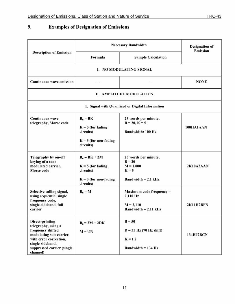
9. Examples of Designation of Emissions
Necessary Bandwidth
Description of Emission Formula
Sample Calculation
Designation of
Emission
I. NO MODULATING SIGNAL
Continuous wave emission
--- --- NONE
II. AMPLITUDE MODULATION
1. Signal with Quantized or Digital Information
Continuous wave telegraphy, Morse code
Bn = BK K = 5 (for fading circuits) K = 3 (for non-fading circuits)
25 words per minute; B = 20, K = 5 Bandwidth: 100 Hz
100HA1AAN
Telegraphy by on-off keying of a tone- modulated carrier, Morse code
Bn = BK + 2M K = 5 (for fading circuits) K = 3 (for non-fading circuits)
25 words per minute; B = 20 M = 1,000 K = 5 Bandwidth = 2.1 kHz
2K10A2AAN
Selective calling signal, using sequential single frequency code, single-sideband, full carrier
Bn = M Maximum code frequency = 2,110 Hz M = 2,110 Bandwidth = 2.11 kHz
2K11H2BFN
Direct-printing telegraphy, using a frequency shifted modulating sub-carrier, with error correction, single-sideband, suppressed carrier (single channel)
Bn = 2M + 2DK M = ½B
B = 50 D = 35 Hz (70 Hz shift) K = 1.2 Bandwidth = 134 Hz
134HJ2BCN

Designation of Emissions, Class of Station and Nature of Service TRC-43
12
Necessary Bandwidth
Description of Emission Formula
Sample Calculation
Designation of
Emission
Telegraphy, multi-channel with voice frequency, error correction, some channels are time-division multiplexed, single-sideband, reduced carrier
Bn = highest central frequency + M + DK M = ½B
15 channels; highest central frequency = 2,805 Hz B = 100 D = 42.5 Hz (85 Hz shift) K = 0.7 Bandwidth = 2.885 kHz
2K89R7BCW
2. Telephony (Commercial Quality)
Telephony, double-sideband (single channel)
Bn = 2M M = 3,000 Bandwidth = 6 kHz
6K00A3EJN
Telephony, single-sideband full carrier (single channel)
Bn = M M = 3,000 Bandwidth = 3 kHz
3K00H3EJN
Telephony, single-sideband, suppressed carrier (single-channel)
Bn = M - lowest modulation frequency
M = 3,000 Lowest modulation frequency = 300 Hz Bandwidth = 2.7 kHz
2K70J3EJN
Telephony with separate frequency modulated signal to control the level of demodulated speech signal, single-sideband, reduced carrier (Lincompex) (single channel)
Bn = M Maximum control frequency = 2,990 Hz M = 2,990 Bandwidth = 2.99 kHz
2K99R3ELN

Designation of Emissions, Class of Station and Nature of Service TRC-43
13
Necessary Bandwidth
Description of Emission Formula
Sample Calculation
Designation of
Emission
Telephony with privacy, single-sideband, suppressed carrier (two or more channels)
Bn = NcM - (lowest modulation frequency in the lowest channel)
Nc = 2 M = 3,000 Lowest modulation frequency = 250 Hz Bandwidth = 5.75 kHz
5K75J8EKF
Telephony, independent sideband (two or more channels)
Bn = sum of M for each sideband
2 channels M = 3,000 Bandwidth = 6 kHz
6K00B8EJN
3. Sound Broadcasting
Sound broadcasting double-sideband
Bn = 2M M may vary between 4,000 and 10,000, depending on the quality desired
Speech and music
M = 4,000 Bandwidth = 8 kHz
8K00A3EGN
Sound broadcasting, single-sideband, reduced carrier (single channel)
Bn = M M may vary between 4,000 and 10,000, depending on the quality desired
Speech and music M = 4,000 Bandwidth = 4 kHz
4K00R3EGN
Sound broadcasting, single-sideband, suppressed carrier
Bn = M - lowest modulation frequency
Speech and music M = 4,500 Lowest modulation frequency = 50 Hz Bandwidth = 4.45 kHz
4K45J3EGN
Designation of Emissions, Class of Station and Nature of Service TRC-43
14
Necessary Bandwidth Description of Emission
Formula Sample Calculation
Description of
Emission
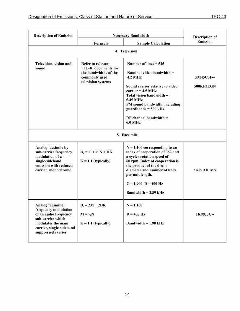
4. Television
Television, vision and sound
Refer to relevant ITU-R documents for the bandwidths of the commonly used television systems
Number of lines = 525
Nominal video bandwidth = 4.2 MHz
Sound carrier relative to video carrier = 4.5 MHz Total vision bandwidth = 5.45 MHz FM sound bandwidth, including guardbands = 500 kHz RF channel bandwidth = 6.0 MHz
5M45C3F--
500KF3EGN
5. Facsimile
Analog facsimile by sub-carrier frequency modulation of a single-sideband emission with reduced carrier, monochrome
Bn = C + ½ N + DK
K = 1.1 (typically)
N = 1,100 corresponding to an index of cooperation of 352 and a cycler rotation speed of 60 rpm. Index of cooperation is the product of the drum diameter and number of lines per unit length.
C = 1,900 D = 400 Hz Bandwidth = 2.89 kHz
2K89R3CMN
Analog facsimile; frequency modulation of an audio frequency sub-carrier which modulates the main carrier, single-sideband suppressed carrier
Bn = 2M + 2DK M = ½N K = 1.1 (typically)
N = 1,100 D = 400 Hz Bandwidth = 1.98 kHz
1K98J3C--

Designation of Emissions, Class of Station and Nature of Service TRC-43
15
Necessary Bandwidth Description of Emission
Formula Sample Calculation
Designation of
Emission
6. Composite Emissions
Double-sideband, television relay
Bn = 2C + 2M + 2D Video limited to 5 MHz, audio on 6.5 MHz, frequency modulated with sub-carrier deviation of 50 kHz
C = 6.5x10⁶
D = 50 x103 Hz
M = 15,000
Bandwidth = 13.13 MHz
13M1A8W--
Double-sideband radio-relay system, frequency division multiplex
Bn = 2M 10 voice channels occupying base band between 1 kHz and 164 kHz
M = 164,000
Bandwidth = 328 kHz
328KA8E--
Double-sideband emission of VOR with voice
(VOR = VHF omnidirectional radio range)
Bn = 2Cmax+ 2M + 2DK
K = 1 (typically)
The main carrier is modulated by: - a 30 Hz sub-carrier - a carrier resulting from a 9,960 Hz tone - a telephone channel - a 1,020 Hz keyed tone for continual Morse identification Cmax = 9,960 M = 30 D = 480 Hz Bandwidth = 20.94 kHz
20K9A9WWF
Independent sidebands; several telegraph channels with error correction together with several telephone channels with privacy; frequency division multiplex
Bn = sum of M for each sideband
Normally composite systems are operated in accordance with standardized channel arrangements (e.g. Rec. ITU-R F.348)
3 telephone channels and 15 telegraphy channels
Bandwidth = 12 kHz
12K0B9WWF

Designation of Emissions, Class of Station and Nature of Service TRC-43
16
Necessary Bandwidth Description of Emission
Formula Sample Calculation
Designation of Emission
III. FREQUENCY MODULATION
1. Signal with Quantized or Digital Information
Telegraphy without error correction (single channel)
Bn = 2M + 2DK M = ½B K = 1.2 (typically)
B = 100 D = 85 Hz (170 Hz shift) Bandwidth = 304 Hz
304HF1BBN
Telegraphy, narrow-band direct printing with error correction (single channel)
Bn = 2M + 2DK M = ½B K = 1.2 (typically)
B = 100 D = 85 Hz (170 Hz shift) Bandwidth = 304 Hz
304HF1BCN
Selective calling signal Bn = 2M + 2DK M = ½B K = 1.2 (typically)
B = 100 D = 85 Hz (170 Hz shift) Bandwidth = 304 Hz
304HF1BCN
Four-frequency duplex telegraphy
Bn = 2M + 2DK B = Modulation rate (Bd) of the faster channel
If the channels are synchronized,
M = ½B (Otherwise: M = 2B) K = 1.1 (typically)
Spacing between adjacent frequencies = 400 Hz
Synchronized channels: B = 100 M = 50 D = 600 Hz Bandwidth = 1.42 kHz
1K42F7BDX

Designation of Emissions, Class of Station and Nature of Service TRC-43
17
Necessary Bandwidth
Description of Emission
Formula Sample Calculation
Designation of
Emission
2. Telephony (Commercial Quality)
Commercial telephony Bn = 2M + 2DK K = 1 (typically, but under certain conditions, a higher value of K may be necessary)
For an average case of commercial telephony,
D = 5,000 Hz M = 3,000 Bandwidth = 16 kHz
16K0F3EJN
3. Sound Broadcasting
Sound broadcasting Bn = 2M + 2DK K = 1 (typically)
Monaural D = 75,000 Hz M = 15,000 Bandwidth = 180 kHz
180KF3EGN
4. Facsimile
Facsimile by direct frequency modulation of the carrier; black and white
Bn = 2M + 2DK M = ½N K = 1.1 (typically)
N = 1,100 elements/sec D = 400 Hz Bandwidth = 1.98 kHz
1K98F1C--
Analog facsimile Bn = 2M + 2DK M = ½N K = 1.1 (typically)
N = 1,100 elements/sec D = 400 Hz Bandwidth = 1.98 kHz
1K98F3C--

Designation of Emissions, Class of Station and Nature of Service TRC-43
18
Necessary Bandwidth
Description of Emission
Formula Sample Calculation
Designation of
Emission
5. Composite Emissions (see Table 1)
Radio relay system, frequency division multiplex
Bn = 2fP + 2DK K = 1 (typically)
60 telephone channels occupying baseband between 60 kHz and 300 kHz; rms per channel deviation: 200 kHz
Continuity pilot at 331 kHz produces 100 kHz rms deviation of main carrier
D = 200 x 103 x 3.76 x 2.02 = 1.52 x 10⁶ Hz
fP = 0.331 x 10⁶ Hz Bandwidth = 3.702 MHz
3M70F8EJF
Radio relay system; frequency division multiplex
Bn = 2M + 2DK K = 1 (typically)
960 telephone channels occupying baseband between 60 kHz and 4,028 kHz; rms per channel deviation: 200 kHz Continuity pilot at 4,715 kHz produces 140 kHz rms deviation of main carrier D = 200 x 103 x 3.76 x 5.5 = 4.13 x 10⁶ Hz M = 4.028 x 10⁶ fP = 4.715 x 10⁶ (2M + 2DK)>2 fP Bandwidth = 16.3 MHz
16M3F8EJF
Radio relay system; frequency division multiplex
Bn = 2fP 600 telephone channels occupying baseband between 60 kHz and 2,540 kHz; rms per channel deviation: 200 kHz; continuity pilot at 8,500 kHz produces 140 kHz rms deviation of main carrier. D = 200 x 103 x 3.76 x 4.36 = 3.28 x 10⁶ Hz; M = 2.54 x 10⁶ K = 1 fP = 8.5 x 10⁶ (2M + 2 DK) < 2fP Bandwidth = 17 x 106 = 17 MHz
17M0F8EJF
Necessary Bandwidth

Designation of Emissions, Class of Station and Nature of Service TRC-43
19
Description of Emission
Formula Sample Calculation Designation of
Emission
Amplitude modulation is used to modulate a carrier with digital bit stream.
Bn = 2BK K = 1 (typically)
Microwave system is digitally modulated at a rate of 5 megabits per second. The carrier is amplitude modulated and 4 signalling states are used. B = R/(log2 4) = 5,000,000/( log2 4) = 2,500 kilobaud
Bandwidth = 5.0 MHz
5M00A1WDN
IV. PULSE MODULATION
1. Radar
Unmodulated pulse emission
Bn = 2K/t K depends upon the ratio of pulse duration to pulse rise time. Its value usually falls between 1 and 10, and in many cases, it does not need to exceed 6.
Primary Radar Range resolution: 150 m.
K = 1.5 (triangular pulse
where t ≃ tr, only components down to 27 dB from the strongest are considered)
Then: t = 2 x (range resolution) / velocity of light = 2 x 150/(3 x 108) = 1 x 10⁻⁶ seconds Bandwidth = 3 MHz
3M00P0NAN

Designation of Emissions, Class of Station and Nature of Service TRC-43
20
Necessary Bandwidth
Description of Emission
Formula Sample Calculation
Designation of
Emission
2. Composite Emissions
Radio relay system Bn = 2K/t K = 1.6
Pulse position modulated by 36 voice channel baseband
Pulse width at half amplitude = 0.4 μsec
Bandwidth = 8 MHz
(Bandwidth independent of the number of voice channels)
8M00M7EJT
V. MISCELLANEOUS
Orthogonal frequency division multiplexing (OFDM) or coded OFDM (COFDM)
Bn = Ns.K 53 active sub-carriers are used, each spaced 312.5 kHz apart (K=53 and Ns=312.5 kHz). Data sub-carriers can be BPSK, QPSK, QAM modulated.
Bn = 312.5 kHz x 53 = 16.6 MHz
16M6W7D
Binary Frequency Shift Keying
If (0.03 < 2D/R < 1.0),
then:
Bn = 3.86D + 0.27R
If (1.0 < 2D/R < 20)
then:
Bn =2.4D + 1.0 R
Digital modulation used to send 1 megabit per second by frequency shift keying with 2 signalling states and 0.75 MHz peak deviation of the carrier.
R = 1 x 106 bits per second;
D = 0.75 x 10⁶ Hz;
Bn = 2.8 MHz
2M80F1DBC
Designation of Emissions, Class of Station and Nature of Service TRC-43
21
Necessary Bandwidth Description of Emission
Formula Sample Calculation
Designation of
Emission
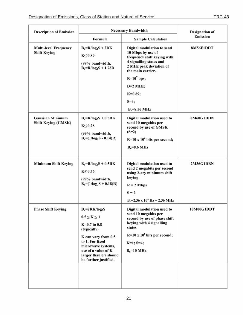
Multi-level Frequency Shift Keying
Bn=R/log2S + 2DK
K≤ 0.89
(99% bandwidth, Bn=R/log2S + 1.78D
Digital modulation to send 10 Mbps by use of frequency shift keying with 4 signalling states and 2 MHz peak deviation of the main carrier.
R=107 bps;
D=2 MHz;
K=0.89;
S=4;
Bn=8.56 MHz
8M56F1DDT
Gaussian Minimum Shift Keying (GMSK)
Bn=R/log2S + 0.5RK
K≤ 0.28
(99% bandwidth, Bn=(1/log2S - 0.14)R)
Digital modulation used to send 10 megabits per second by use of GMSK (S=2)
R=10 x 106 bits per second;
Bn=8.6 MHz
8M60G1DDN
Minimum Shift Keying Bn=R/log2S + 0.5RK
K≤ 0.36
(99% bandwidth, Bn=(1/log2S + 0.18)R)
Digital modulation used to send 2 megabits per second using 2-ary minimum shift keying:
R = 2 Mbps
S = 2
Bn=2.36 x 10⁶ Hz = 2.36 MHz
2M36G1DBN
Phase Shift Keying Bn=2RK/log2S
0.5 ≤ K ≤ 1
K=0.7 to 0.8 (typically)
K can vary from 0.5 to 1. For fixed microwave systems, use of a value of K larger than 0.7 should be further justified.
Digital modulation used to send 10 megabits per second by use of phase shift keying with 4 signalling states
R=10 x 106 bits per second;
K=1; S=4;
Bn=10 MHz
10M00G1DDT
Designation of Emissions, Class of Station and Nature of Service TRC-43
22
Necessary Bandwidth Description of Emission
Formula Sample Calculation
Designation of
Emission
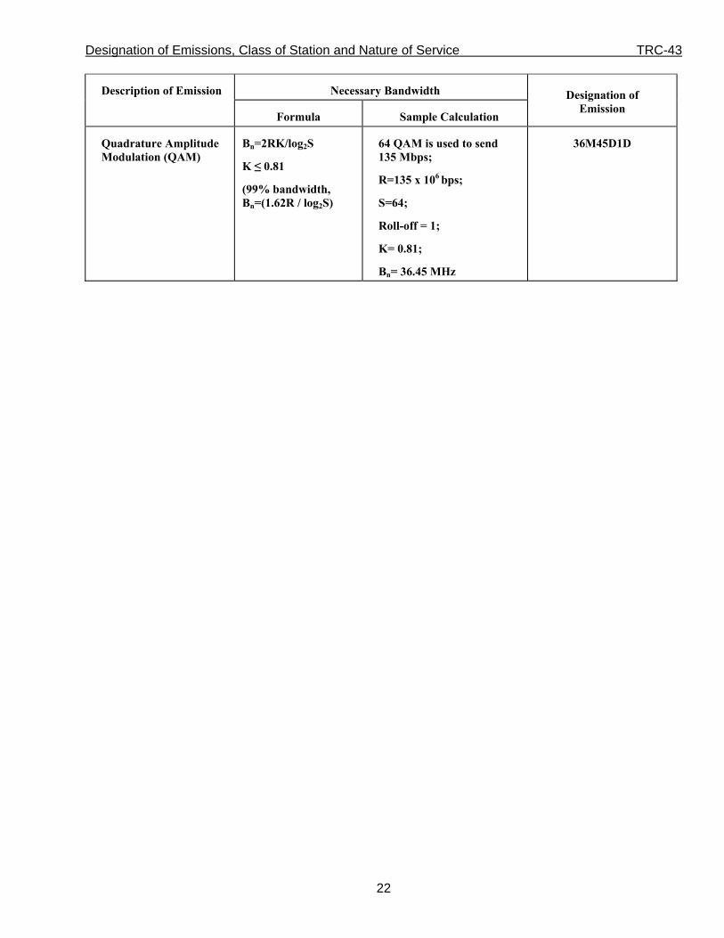
Quadrature Amplitude Modulation (QAM)
Bn=2RK/log2S
K ≤ 0.81
(99% bandwidth, Bn=(1.62R / log2S)
64 QAM is used to send 135 Mbps;
R=135 x 106 bps;
S=64;
Roll-off = 1;
K= 0.81;
Bn= 36.45 MHz
36M45D1D

Designation of Emissions, Class of Station and Nature of Service TRC-43
23
Table 1 ‒ Multiplying Factors for Use in Computing D, Peak Frequency Deviation,
in FM Frequency Division Multiplex (FM/FDM) Multi-Channel Emissions
For FM-FDM systems, the necessary bandwidth is:
Bn=2M + 2DK
The value of D, or peak frequency deviation, in these formulas for Bn is calculated by multiplying the rms value of per-channel deviation by the appropriate “multiplying factor” shown below.
In the case where a continuity pilot of frequency fp exists above the maximum modulation frequency M, the general formula becomes:
Bn = 2fp + 2DK
In the case where the modulation index of the main carrier produced by the pilot is less than 0.25 and the rms frequency deviation of the main carrier produced is less than or equal to 70% of the rms value of per-channel deviation, the general formula becomes either:
Bn = 2 fp or Bn = 2M + 2DK,
whichever is greater.
Number of telephone channels, Nc Multiplying factor12
(Peak factor) x antilog (value in dB above modulation reference level / 20)
3 < Nc < 12 4.47 x antilog (a value in dB specified by the equipment manufacturer or station licensee, subject to administration approval / 20)
12 ≤ Nc < 60 3.76 x antilog ((2.6 + 2 log Nc) / 20)
Number of telephone channels, Nc Multiplying factor13
(Peak factor) x antilog(value in dB above modulation reference level / 20)
60 ≤ Nc < 240 3.76 x antilog ((-1+4 log Nc) / 20)
Nc ≥ 240 3.76 x antilog ((-15+10log Nc) / 20)
12 In the above chart, the multipliers 3.76 and 4.47 correspond to peak factors of 11.5 dB and 13.0 dB respectively. It is
recognized that some systems that carry appreciable quantities of data or information other than voice may have different loading factors than the preferred ones shown above.
13 In the above chart, the multipliers 3.76 correspond to peak factors of 11.5 dB.