Embed Size (px)
Citation preview

Paper presented @ Automotive Noise and Vibration Congress, 27th-28th Jan 2016, Pune, India
Design Validation of an Integrated Transmission System
Vikas Manjrekar1, S Shamasundar2*, Samarth Shrivastava3
1 Executive Vice President, R&D& Strategic Sourcing, AVTEC Ltd, Pithampur, MP. Email: [email protected] 2* Managing Director, ProSIM R&D Pvt Ltd, Bangalore. Email: [email protected]
3CAE Engineer, R&D, AVTEC Ltd, Pithampur, MP. Email: [email protected]
ABSTRACT
Authors have worked on design and development of an integrated transmission system for a 4x4
SUV. Design, design verification and validation, design optimisation of torque transfer components - gear
pairs, shafts, synchroniser, differential, bearings etc., and housings were carried out. Multi-body dynamic
analysis has been carried out to determine time dependent bearing loads. Finite element analysis was
conducted to determine the stresses, vibrations and validate the design. Durability assessment was carried
out to determine the fatigue life of all the components in the transmission system, considering the duty cycle
loads as per customer statement of requrements. Transient dynamic analysis of the transmission system
was carried out. Resonance analysis is carried out to determine the critical speed and components causing
resonance /noise. Acoustic analysis was carried out to predict the noise generated. Using virtual
prototyping principles, the design validation of the transmission system was done and design parameters
were optimised. Gear engagement analyses, synchroniser engagement behaviour, transmission efficiency,
have been calculated.
Physical prototyping and testing was carried out for design validation. Vibration, Noise, and durability were
measured in the test rigs. Paper discusses the issues in modelling (multi-body dynamic simulation, finite
element analysis, and durability) and also in the testing practices. Authors discuss the challenges faced in
the development process and ways to overcome typical problems in the development. Commercially
available software tools such as SIMPACK, ABAQUS, and FESAFE have been used in this study.
Key Words: NVH, durability, fatigue life, gear box, transmission, differential, synchroniser, FEM analysis,
resonance, noise isolation, SIMPACK, FESAFE, ABAQUS, Modal Analysis, Harmonic Analysis.
INTRODUCTION:
Gear box design and development is a complex exercise calling for interdisciplinary expertise. OEM
demands on higher performance (such as NVH, durability and so on,) are continuously increasing. Using
technology, methods, guidelines, and tools available at their fingertips, designers can develop superior
designs. Only by effective utilization of research budget an organization can develop improved design,
which can result in cost savings and systematic production [1].
The integrated transmission reported in this paper has been designed, verified and validated, and
qualified deploying principles of virtual as well as physical prototyping and testing. These have been done
as per the customer statement of requirement and customer prescribed testing standards.
Effect of the accuracies of manufacturing gears, bearings, housing & all torque transfer on gear box
performance are analyzed. The design objectives considered in design were the customer prescribed
levels of load capacity, reliability, service life (which comprises of endurance life & fatigue life. Noise &

Paper presented @ Automotive Noise and Vibration Congress, 27th-28th Jan 2016, Pune, India
vibration test for this transmission was carried out for isolation / elimination of unwanted noise &
vibration from the system.
Design of Gearbox:
The transmission (gearbox) discussed in this paper is an integrated transmission & transfer case & shown
in Figure-1. This is different from conventional transmission in many aspects. Conventional transmission
which has been used in AWD vehicles has transfer case separately attached where as integrated
transmission has transfer case mounted directly on rear cover housing for compactness and NVH
improvement.
Design of a 5-speed transmission with an integrated transfer case has many challenges. First of all a new
product development plan has to be made and the work flow has to be in line with the plan. Challenges
like material selection for all the torque transfer parts, housing parts, synchronizer, bearings and other
miscellaneous parts has to be considered appropriately. Environmental condition of usage from -30 /+50
degree Celsius for material was a major challenge for performance and durability. Engineering analysis
of design such as DFMEA, PFMEA, and GD&T have been done since this was a new product.
Figure-1: Integrated Transmission & Transfer Case
5 speed manual transmission Motor shift transfer case

Paper presented @ Automotive Noise and Vibration Congress, 27th-28th Jan 2016, Pune, India
The process for new product design and development has followed various stage gate process which
capture voice of customer (VOC) and business viability, translating VOC in design followed by design for
performance, fitment, manufacturing, (for quality and cost) and serviceability before signing off with
customer. The main task of design process is to create a relationship between the product function,
product structure & complimenting with requirement with other critical aggregates (engine, chassis, Axles
etc) of vehicle.
Product function for integrated transmission is to run vehicle in 5 forward speeds & 1 reverse speed within
the specified torque & rpm range. It has also a transfer case with differential which makes the vehicle
alltime 4WD and can accommodate differential speed in front and rear axle. To increase flexibility and
feature in the system to fulfilling customer requirements the transfer case has been designed with 2
speeds reduction (low & high) & a differential. Differential facilitates in locking & unlocking the power
flowing in forward & reverse axle. In lock state both the forward & reverse axle receive equal torque & in
unlock state both the axle receive unequal torque & power transmission.
This transmission has many design changes with respect to conventional 5 speed transmission. Therefore,
tunneling of transmission in the vehicle body has been analyzed to improve the compatibility and
performance of other critical aggregates. Corresponding system assemblies combining components for a
satisfactory design structure has been developed to fulfill assembly requirements. One of the most
weighted quality assessment parameter of gearbox nowadays is acoustic noise level. A gearbox is rated
according to the noise level depending on the customer acceptability with bench mark vehicles /
competitions [2].
A full consecrated test rig has been installed with 3 electric servo control motors for load & speed
application. Durability cycle & fatigue cycle have been developed for accelerated testing by designers with
field usage and B10 life specified by customer. Performance measurement has been done by developing
durability cycles i.e. endurance cycle & fatigue cycle as per voice of customer. Table 1 illustrates load
cases for durability testing transmission on rig.
Table1. Load Cases of durability cycle for transmission
S.no. % of total time Front Axle (% of total torque) Rear Axle (% of total torque)
1 10% 100% 100%
2 30% 120% 80%
3 30% 80% 120%
4 10% 140% 60%
5 10% 60% 140%
6 5% 200% 0%
7 5% 0% 200%
Design Validation:
Optimised design was finalized based on the simulation and modeling explained in the next sections.
Prototypes of the optimized model were manufactured for design validation by testing. Durability cycle
for integrated transmission has been developed & the transmission has been tested for 752 hours.

Paper presented @ Automotive Noise and Vibration Congress, 27th-28th Jan 2016, Pune, India
Durability & fatigue cycles have been done for 2 transmission prototypes. Figure-2 shows the test rig used
for testing these transmissions.
While testing the performance of a gearbox it is necessary to test the torque carrying capacity of the
gearbox at different speeds and noise generation in normal running conditions. Theoretical calculations
using ISO (International Standards Organization) & AGMA (American Gear Manufacturing Association)
standards were used for specifying torque ratings. A validation test rig with AC regenerative motors
simulating 4WD environment was used for validation. Since the gear performance is highly dependent on
number of parameters such as material, design, manufacturing, operation & environment therefore a
noise insulated acoustic chamber has been built for testing [3]. This rig also offers a versatile loading
environment where actual working conditions like oil temperature sensing, shift feel, vehicle inclination,
traction (loading) can be simulated in laboratory testing.
Figure-2: Test Rig for Integrated Transmission
Modeling and Simulation:
A model of the complete integrated transmission system (consisting of gear pairs, bearings, shafts,
housing, differential, synchronizer etc.,) has been developed to create virtual prototype and simulate all
the tests virtually. Simulation involved in creating a digital mockup of the assembly, developing discretized
models, conducting multi-body dynamic simulations, finite element analysis, acoustic analysis, and
durability analysis and fatigue life assessment. Non-linear contact analysis has been performed to
account for the contact friction conditions.
Multi-body dynamic Simulation
For dynamic analysis of drive train, multibody dynamics (MBD) simulation software SIMPACK is used to build the virtual model and to simulate. In a drive train, meshing of the gear teeth is a common source of internal excitation [4]. Gearbox housing, transfer case and shafts are considered as flexible when modeling in SIMPACK. Flexible models in FE can have a large number of degree of freedoms (DOF’s), in the order of magnitude of ten thousand up to several hundred thousand. The reduction to a smaller set of DOF’s, in the order of magnitude of one up to ten, which can be imported in to SIMPACK is done with the component mode synthesis (CMS) technique. The Craig-Bampton method is a well-established CMS technique [7]. This reduction involves the creation of a set of static constraint modes and fixed-interface normal modes with their corresponding Eigen frequencies [5]. The accuracy of the flexible body in the multibody model is determined by the accuracy of the FE model, and the number of modes that were taken into account during the CMS reduction [6]. Gear wheels are modeled in SIMPACK using inbuilt
Paper presented @ Automotive Noise and Vibration Congress, 27th-28th Jan 2016, Pune, India
modeling element. Backlash, multiple tooth contact and material properties are all taken into account in modeling. Shafts are mounted on the housing with nonlinear bearing stiffness and damping values. Synchronizer components (synchro cone, block rings, hub and sleeve) are modeled as sub-model and assembled with the main model. Synchronizer shifter force has considered to engaging different speed. Transmission and Transfer Case are modeled as sub assembly in Main model via sub structuring. Load cases is applied to the main model via sub structuring. Figure-3 shows the complete gearbox system topology in a 2D framework. Topology diagram helps to understand the load transfer path in an intuitive way.
Figure-3. Topology diagram of complete gearbox system
A multi-body dynamic (MBD) model thus created in SIMPACK, is used to extract time dependent bearing forces. Gearbox is mounted accounting for mounting stiffness and damping values. The sensor elements (used in vibration and noise testing) are modeled at the probe locations to extract acceleration. Input torque and speed are applied at the input shaft and for output shaft the reverse torque is applied.
Finite Element Analysis, Durability assessment
Authors have used a commercial software ABAQUS for finite element analysis and FESAFE for fatigue life
(damage) and durability assessment. Standards assumptions such as isotropic material have been invoked.
For FEM analysis, second order tetrahedral elements are used.
The stress results from FE analysis is used in durability analysis of housings and TT components. The
fatigue properties are assigned for all components and as per vehicle usage conditions the duty cycle load
is considered during durability analysis. The fatigue life (number of cycles) is estimated for transmission
assembly. The number of cycles observed in housing assembly is 10E7 cycles. Issues associated with

Paper presented @ Automotive Noise and Vibration Congress, 27th-28th Jan 2016, Pune, India
fatigue damage (life) and durability assessment have been described by other researchers [8]. Care to be
taken during fatigue life and fatigue hot spot assessment are described in [9].
Acoustic analysis is carried out to predict the noise generated by Finite element method. Major
components contributing to the noise in the integrated Transmission housings, TT parts were considered
in the analysis. Air volume is considered as a cylinder shape (acoustic structure) from transmission axis
and air media properties are assigned to acoustic elements. The acoustic structure is discretized as per
wave length criteria and analysis is done at the 1/3rd Octave band and the average sound pressure level
(dB) at the required probe location for different load cases were extracted at the corresponding
frequencies.
Results and discussion:
Due to paucity of space limited results are presented here in this paper. Figure-4 shows the input torque,
and output torques at rear and front drive shafts. Gear box transmission efficiency is calculated using the
input and output torques. Efficiency of gearbox is associated primarily with tooth friction and lubrication
churning losses. Churning losses are independent nature of gears and gears ratios. Input torque applied
to input shaft and output torque are measured from the system. Efficiency of gearbox due to friction was
found in the range of 98% to 99%. Time dependent bearing force history calculated by SIMPACK is shown
in Figure-5. This is converted into frequency dependent forces by using FFT (Fast Fourier Transformation)
in SIMPACK post processing. The Bearing forces are used to conduct structural analysis in FE program.
Efficiency of the gearbox for different gear engagement was calculated considers the gear friction. The
FFT converted bearing forces are used in acoustic analysis in FE program. Resonance analysis is carried
out to find out critical components (which contribute more vibrational signals to the resultant vibration
of whole system) in system. Acceleration at probe locations in gearbox housing are extracted from the
SIMPACK sensor elements. Using order analysis in SIMPACK, the critical components in the system for all
gear engagement was identified. For example, the Figure-6 shows, at a particular speed acceleration is
higher for the 3rd gear pair which is having meshing frequency 21Hz. From the same plot we can observe
another gear pair from transfer case of meshing frequency 28Hz is accelerating. TC gear pair is accelerating
at second harmonic speed can be observed at 56th order. The speed synching time over the frictional
torque for applied shifter force has analyzed for each engagement. Time dependent bearing load was
applied to acoustic analysis to find out noise generated in each speed range.

Paper presented @ Automotive Noise and Vibration Congress, 27th-28th Jan 2016, Pune, India
Figure-4: Input and output torques for efficiency calculation.
Figure-5: Bearing Load at TC Input Shaft
Figure-6: Campbell Diagrams in 3D (order, RPM, acceleration) and 2D (Order, acceleration)

Paper presented @ Automotive Noise and Vibration Congress, 27th-28th Jan 2016, Pune, India
A modal dynamic analysis is conducted. Some of the dominant mode shapes of transmission system is
shown in figure-7.
Mode – 1 (358.11 Hz) Mode – 2 (362.73 Hz)
Mode – 6 (617.06 Hz) Mode – 7 (642.89 Hz)
Figure-7: Mode shapes of Transmission system.
Von Misses stress observed on the transmission assembly for a particular static analysis case is shown in
Figure-8. Stress / strain fields calculated by finite element analysis are used to carry out the fatigue life
and durability analysis. Lifetime of transmission components was determined. Towards this the life
available (described as number of cycles for fatigue crack initiation) at the fatigue hot spot had to be more
than the prescribed limit, viz., 10E7 cycles. This would mean available design life of the entire integrated
system is higher than the life expected by customer, and would meet and pass the specification.
Figure-8: von Misse’s stress on transmission housing assembly
Paper presented @ Automotive Noise and Vibration Congress, 27th-28th Jan 2016, Pune, India
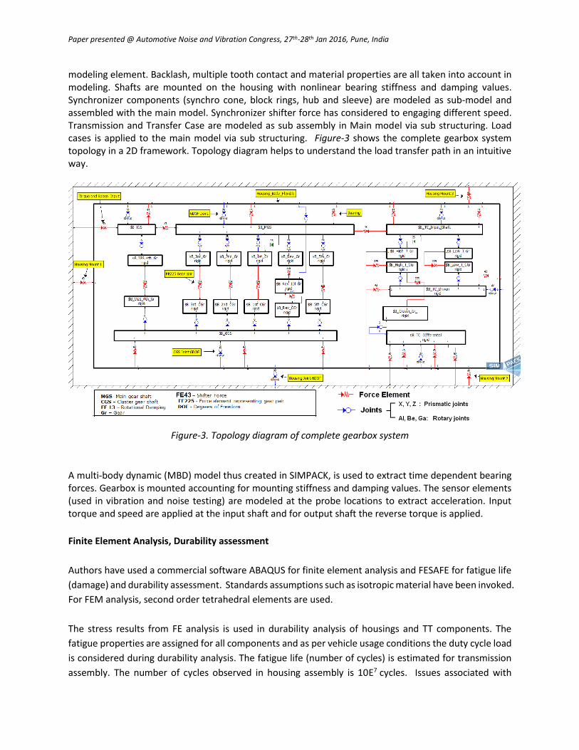
The noise level extracted for one of the load cases at a particular probe location is shown in Figure-9.
Figure-9: Noise level for a particular gear engagement case at a probe location
Conclusions:
A methodology of design and development of a new integrated gear transmission system for 4x4
SUV (AWD) is explained.
By using a combination of virtual and physical prototyping and testing, the design objectives set
forth by the customer was achieved. This included
o Achieving a durability for 10e7Cycles
o Achieving a noise level less than 73 dBA
o Optimising the structure with sufficient factor of safety.
Using simulation techniques cost and time saving has been achieved in the design and
development cycle.
References:
1. Hales Crispin, 2003. “Respect Design or Expect Disaster!”International Conference On Engineering
Design, Iced 03 Stockholm, August 19-21, 2003.
2. Ognjanovic M. &Milutinovic M., 2013. “Design for Reliability Based Methodology for Automotive
Gearbox Load Capacity Identification”, Journal of Mechanical Engineering, Vol 59(2013)5, 311-
322.
3. Rosic et.al, 2005. “Optimum Design of Multispeed Gearboxes and Modeling of Transmission Components”, V International Scientific Conference, Heavy Machinery-HM'05 Kraljevo.
4. Alexander Neubauer,2014” Simulation Methods for NVH-Development of a Double Clutch Transmission Gearbox “ , SIMPACK User Meeting .
5. F. Vanhollebek, J. Helsen2, J. Peeters1, D. Vandepitte2, W. Desmet2,”Combining multibody and acoustic simulation models for wind turbine gearbox NVH optimization

Paper presented @ Automotive Noise and Vibration Congress, 27th-28th Jan 2016, Pune, India
6. Dr. Berthold Schlecht, Tobias Schulze, “Multibody system Simulation of Wind turbine for Determination of Additional Dynamic loads”, SIMPACK User Meeting.
7. SIMPACK Documentation 8. Wufu Ma, "Strength and fatigue calculations of a planet gear carrier", (PERA Technology (Beijing)
Co. Ltd., Chengdu 610016, Sichuan, P.R.China) 9. Fe-safe 6.5 User Manual. Dassault Systems