Embed Size (px)
Citation preview
Design techniquesThe design process involves
1.Developing conceptual view of the system2.Establishing system structure
3.Identifying data streams and data stores4.decomposing high level functions into sub functions
5.Establishing relationships and interconnections

• Developing a conceptual view of a software system involves determining the type of system to be built.
• The system may be database system,etc.• A data store is a conceptual data structure.• During external and architectural design, one
identify stack, queue or file. • The exact implementation is known only the
detailed design• During external and architectural design, data
structures are defined as data abstraction.
• Data stores and data streams are specified using data flow diagrams, data dictionaries and data abstraction techniques.
• External data streams are identified during software requirements analysis and external design.
• Internal data streams and data stores are developed during architectural design.
• Several techniques developed for software design
• 1.stepwise refinement• 2. levels of abstraction• 3. structured design• 4. integrated top-down development• 5. jackson design method• These techniques are called as design
methodlogies.
• Design techniques are based on top-down and bottom-up design strategies.
• In top-down, attention is focused on global aspects of the overall system.
• As the design progresses, the system is decomposed into subsystems and more consideration is given to specific issues.
• Backtracking is fundamental to top-down approach.• To minimize backtracking, designers use mixed
strategy .• The advantage of top down strategy is that
attention is given to customer’s needs, user interfaces.

• In the bottom up approach, the designer identify a set of objects, actions and relationships to the problem solution.
• Bottom up design require redesign and design backtracking.
• The success of bottom-up design depends on identifying the proper se of primitive ideas sufficient to implement the system.
• Bottom up design and implementation permits assessment of subsystem performance during system evolution.
• Using top-down methods, performance evaluation is not known until the entire ysstem is assembled.

• 5.4.1 stepwise refinement• It is a top-down technique for decomposing a
system from high-level specifications into more elementary levels.
• It is known as ‘stepwise program development’ and ‘successive refinement’.
• The activities are1. Decomposing design decisions to elementary
levels.2. Isolating design aspects that are not truly
interdependent.
3.Postponing decisions concerning representation details as long as possible.
4. Carefully demonstrating that each successive step in the refinement process is a faithful expansion of previous steps.
Stepwise refinement begins with specifications derived during requirements analysis and external design.
The problem is first decomposed into a few major processing steps that will demonstrably solve the problem.
The process is then repeated for each part of the system until it is decomposed in sufficient detail so that implementation in an executable programming language is straightforward.

• The early stages of refinement are typically stated in an informal pseudo code that becomes more precise as the refinement proceeds.
• The resulting design is close to, statements from the implementation language.
• Successive refinement is used to perform detailed design of the individual modules in a software product.
• The major benefits of stepwise refinement as a design technique are:
1. top-down decomposition2. incremental addition of detail3. postponement of design decisions4. Continual verification of consistencyUsing stepwise refinement, a problem is
segmented into small, manageable pieces and the amount of detail that is dealt is minimized.

• 5.4.2 Levels of abstraction• Levels of abstraction is described by dijkstra as a
bottom up design technique.• In his system, each level of abstraction is
composed of a group of related functions• Some functions are visible some are not visible.• The internal functions are used to perform tasks
common to the work performed.• Each level of abstraction performs a set of
services for the functions on the next higher level of abstraction.
• Each level of abstraction has exclusive use of certain resources.
• Other levels are not permitted to access.• Higher level functions invoke lower level
functions.• But lower level functions cannot invoke any
higher level functions.

• 5.4.3 structured design• Structured design was developed by
constantine as a top-down technique for architectural design of software systems.
• The basic approach is systematic conversion of data flow diagrams into structure charts.
• As in section 5.2, coupling measures the degree to which two distinct modules are bound together.
• Cohesion is a measure of the relationship of elements within a module to one another.

• A well designed system exhibits a low degree of coupling between modules and a high degree of cohesion among elements in elements.
• The 1st step in structured design is review and refinement of the data flow diagram developed during requirements definition and external design.
• The 2nd step is to determine whether the system is transform-centered or transaction driven, and to derive a high level structure chart based on this determination
• The 3rd step in structured design is decomposition of each subsystem using guidelines such as coupling, cohesion, information hiding, levels of abstraction, data abstraction, and the other decomposition criteria
• In addition to coupling, cohesion, data abstraction, information hiding and other information hiding and other decomposition criteria, the concepts of “scope of effect” and “scope of control” can be used to determine the relative positions of modules in a hierarchical framework.
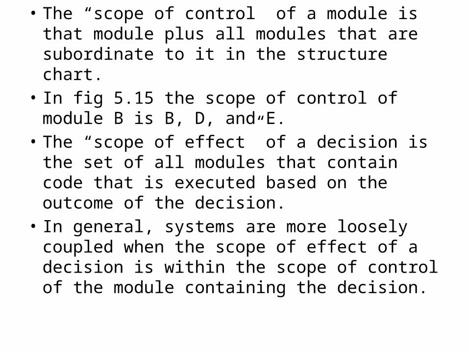
• The “scope of control” of a module is that module plus all modules that are subordinate to it in the structure chart.
• In fig 5.15 the scope of control of module B is B, D, and E.
• The “scope of effect” of a decision is the set of all modules that contain code that is executed based on the outcome of the decision.
• In general, systems are more loosely coupled when the scope of effect of a decision is within the scope of control of the module containing the decision.

• In fig 5.15 suppose execution of some code in module B depends on the outcome of a decision, in module E. either E will return a control flag to B or the decision process will have to be repeated in B.
• The former approach requires additional code to implement the flag and results in control coupling between B and E.
• The latter approach requires duplication of some of E’s code in module B.
• Duplication of code is inefficient and causes difficulties in coordinating changes to both copies if the decision process should change.
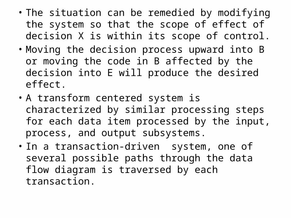
• The situation can be remedied by modifying the system so that the scope of effect of decision X is within its scope of control.
• Moving the decision process upward into B or moving the code in B affected by the decision into E will produce the desired effect.
• A transform centered system is characterized by similar processing steps for each data item processed by the input, process, and output subsystems.
• In a transaction-driven system, one of several possible paths through the data flow diagram is traversed by each transaction.
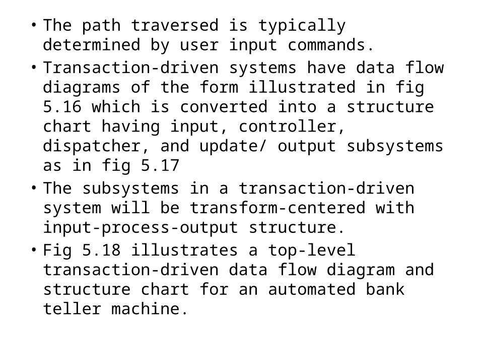
• The path traversed is typically determined by user input commands.
• Transaction-driven systems have data flow diagrams of the form illustrated in fig 5.16 which is converted into a structure chart having input, controller, dispatcher, and update/ output subsystems as in fig 5.17
• The subsystems in a transaction-driven system will be transform-centered with input-process-output structure.
• Fig 5.18 illustrates a top-level transaction-driven data flow diagram and structure chart for an automated bank teller machine.
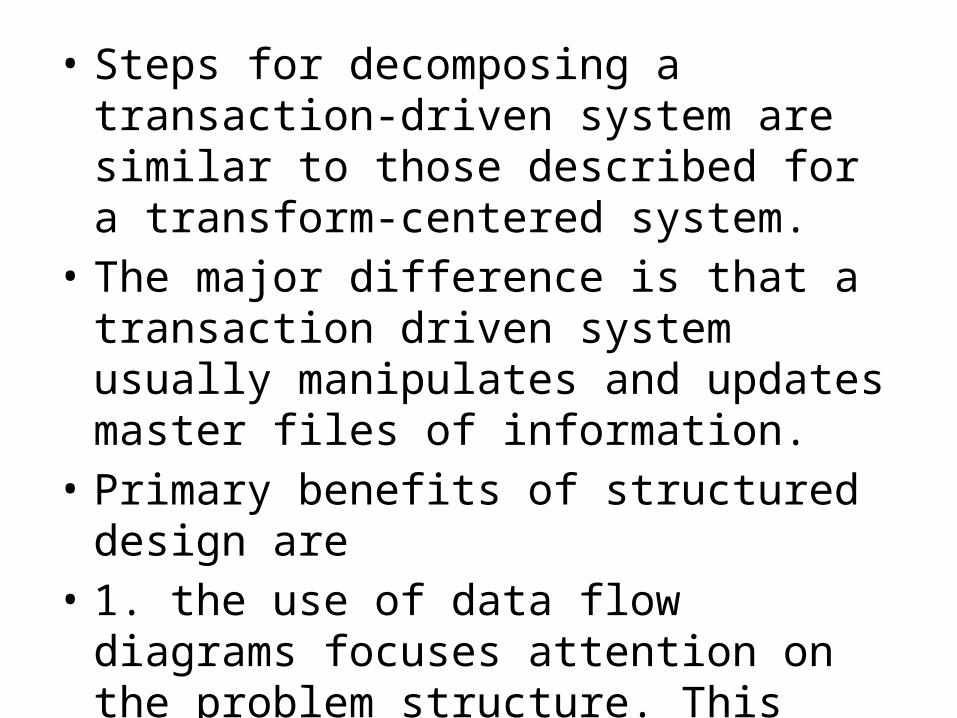
• Steps for decomposing a transaction-driven system are similar to those described for a transform-centered system.
• The major difference is that a transaction driven system usually manipulates and updates master files of information.
• Primary benefits of structured design are• 1. the use of data flow diagrams focuses
attention on the problem structure. This follows naturally from requirements analysis and external design.

• 2. the method of translating data flow diagrams into structure charts provides a method for initiating architectural design in a systematic manner.
• 3. data dictionaries can be used in conjunction with structure charts to specify data attributes and data relationships.
• 4. design heuristics such as coupling and cohesion, and scope of effect and scope of control provide criteria for systematic development of architectural structure and for comparison of alternative design structures.
• 5. detailed design techniques and notations such as successive refinement, can be used to perform detailed design of the individual modules.
• The primary strength of structured design is provision of a systematic method for converting data flow diagrams into top-level structure charts.
• The primary disadvantage of structured design is that are structured as sequences of processing steps.
• Decomposing a system into processing steps is inconsistent with the design criterion of information hiding
• 5.4.4 Integrated top-down development• Integrated top- down development integrates
design, implementation, and testing.• Here, design proceeds top-down from the
highest – level routines.• It has the primary function of coordinating
and sequencing the lower level routines.• Lower level routines may be implementations
of elementary functions• It is explained by the example.
• It is assumed that the design of a system has proceeded to the point illustrated in fig 5.19
• The purpose of procedure MAIN is to coordinate and sequence the GET, PROCESS, and PUT routines.
• These 3 routines communicate through MAIN• SUB1 and SUB2 communicate through PROCESS• The implementation and testing strategy is
illustrated in fig 5.19• The stubs referred to in fig 5.19 are dummy routines
written to simulate sub functions that are invoked higher-level functions.
• As coding and testing progresses, the stubs are expanded into full functional units.
• Design and coding are integrated because expansion of a stub will typically require creation of new stubs to support it.
• Test cases are developed systematically, and each routine is tested in the actual operating environment.
• The advantage of integrated top-down approach is distribution of system integration across the project.
• The primary disadvantage is that early high-level design decisions may have to be reconsidered when the design progresses to lower levels.
• The system is very expensive test harness for newly added procedures.
• It is necessary to first write and test some low-level procedures before proceeding with top-down development.
• Despite these disadvantages, the ability to demonstrate early prototypes of the system using program stubs, and the distribution of system integration throughout the project schedule make top-down development an attractive approach.
• 5.4.5 jackson structured programming•

• 5.4.6 summary of design techniques• The following comments reflect an admittedly
subjective evaluation of the various techniques.• Stepwise refinement provides a general framework
for problem solving by placing emphasis on the importance of proceeding from general concerns to specific details in small incremental steps.
• The greatest strength = the attention focused on verifying that each successive step is a faithful expansion of previous steps.
• The greatest weakness = the foresight required to accomplish top-down decomposition
• It is a valuable technique for detailed design of the individual modules in a software system.
• The greatest strengths of levels of abstraction= the strict hierarchical ordering imposed between levels, the hiding of internal functions within levels, and the sharing of global data only within levels.
• The greatest weakness= the lack of criteria to guide the placement of functions within the hierarchy.
• Structured design is an architectural design technique that involves conversion of data flow diagrams into structure charts.
• The greatest strength = the systematic transition from data flow diagrams to structure charts, the emphasis placed on interfaces when using structure charts, and the use of coupling, cohesion, and other modularization criteria.
• The greatest weakness = the use of data flow diagrams and structure charts decomposes a system into a sequence of processing steps.
• Integrated top-down development strategies integrates design, implementation, and testing.
• Advantages of integrated top-down development include the ability to experiment with successive prototypes as the system evolves, and the gradual integration of subsystems.
• The main disadvantage = the necessity for design backtracking and the potential for considerable rewriting of code.
• Jackson structured programming transforms input and output data structures into a program structure that will map the input files to the output files.
• The greatest strength = the almost mechanical process of creating a program structure from the data structures.
• The primary weakness = the problems of structure clash and backtracking, and the limited amount of creativity possible within the framework of the method.

• 5.5 Detailed Design considerations• Detailed design is concerned with specifying • algorithmic details, • concrete data representation,• interconnections among functions and• data structures and • packaging of the software product.• The starting point for detailed design is an
architectural structure for which algorithmic details and concrete data representations are to be provided.
• Implementation addresses issues of • programming language syntax, • coding style,• internal documentation, and• insertion of testing and debugging probes into the
code.• Detailed design permits• design of algorithms and• data representations at a higher level of
abstraction and • notation than the implementation language
provides.

• Detailed design provides a vehicle for design inspections, structured walkthroughs, and the critical design review.
• The detailed design representation may utilize key words from the implementation language to specify control flow, and declaration statements from the implementation language to specify data representation.
• Product packaging is an important aspect of detailed design.

• Packaging is concerned with the manner in which • global data items are selectively shared among
program units, • specification of static data areas, • packaging of program units as functions and • subroutines, • specification of parameter passing mechanisms, • file structures and file access techniques, and • the structure of compilation units and load modules.• Given the architectural and detailed design
specifications, any programmer familiar with the implementation language should be able to implement the software product.
• 5.6 Real time and distributed system design• In this section, we discuss some of the
problems encountered in designing real-time and distributed systems.
• According to franta, a distributed system consists of a collection of nearly autonomous processors that communicate to achieve a coherent computing system.
• Each processor possesses a private memory, and processors communicate through an interconnection network.

• Major issues in designing a distributed system includes
• The topology of the communication network• Establishing rules for accessing the shared
communication channel.• Allocating application processing functions to
processing nodes in the network.• Establishing rules for process communication
and synchronization.

• The design of distributed systems is complicated by allocating network functionality between hardware and software components of the network.
• Message traffic between nodes must be analyzed to establish the necessary communication rates.
• Reliability issues like loss of communication link or loss of a processing node must be considered.
• Mechanisms for message flow control, error control in response to failures of redundancy checks in arriving messages, systems status monitoring, and network diagnostic techniques must be considered.
• Mechanisms for addressing processes in remote nodes, queue management in the network interconnection devices, message flow control between nodes, allocation of the communication network to various nodes, messages parity error checks, and system status monitoring must be specified.
• Real time systems typically sense and control external devices, respond to external events, and share processing time between multiple tasks.

• A real time network for process control may consist of several minicomputers connected to one or more large processors.
• Each processor is connected to a cluster of real time devices.
• So, processing power is placed at “natual” sites in the system and data can be processed at the point of reception rather than at a central node, thus reducing communication bandwidths.

• Decomposition criteria for distributed real-time systems include the need to maintain process simplicity and to minimize inter process communication bandwidths by communicating simple processed messages rather than raw data.
• Several notations have been developed to support analysis and design of real time and distributed systems.
• They are RSL,SDLP, NPN, communication ports.
• Traditional considerations like hierarchy, information hiding and modularity are important concepts for design of real time systems.
• High level issues of networking, performance and reliability must be analyzed and designed before the component nodes or processes are developed
• 5.7 Test plans• The test plan is the product of software
design.• The test plan specifies• the objectives of testing,• The test completion criteria,• The system integration plan,• Methods to be used on particular modules
and the particular test cases to be used.

• There are 4 types of tests that a software product must satisfy
• Functional tests• Performance tests• Stress tests• Structural tests• Functional tests and performance tests are
based on the requirements specification they are designed to demonstrate that the system satisfies the requirements.

• Functional test cases specify typical operating conditions, typical input values and typical expected results.
• Special values, files and arrays containg identical values, the identity matrix, the zero matrix should be tested.
• Performance tests should be designed to verify response time, execution time, throughput, primary and secondary memory utilization and traffic rates on data channels and communication links.

• Stress tests are designed to overload a system in various ways, such as attempting to sign on more than the maximum allowed number of terminals, processing more than the allowed number of identifiers or static levels, or disconnecting a communication link.
• The purpose of stress testing are to determine the limitations of the system and when the system fails, to determine the manner in which the failure is manifest.
• Stress test provide valuable insight concerning the strengths and weakness of a system
• Structural tests are concerned with examining the internal processing logic of a software system.
• The goal of structural testing is to traverse a specified number of paths through each routine in the system to establish thoroughness of testing.
• 5.8 Milestones, walkthroughs, and inspections• The two major milestones during software design
are the preliminary design review(PDR) and the critical design review(CDR).
• The PDR is typically held near the end of architectural design and prior to detailed design.
• CDR occurs at the end of detailed design and prior to implementation.
• Depending on the size and complexity of the product being developed, the PDR and CDR may be large, formal affairs involving several people, or they may consist of an informal meeting between a programmer and the project leader.

• The major goal of a PDR is to demonstrate that the externally observable characteristics and architectural structure of the product will satisfy
• The customer’s requirements,• Functional characteristics,• Performance attributes,• External interfaces,• User dialogues,• Report formats, • Exception conditions and exception handling, • Product subsets, • Future enhancements to the product• Should be reviewed during the PDR.
• The PDR diagrams given in fig 5.10• One of two outcomes is likely for a PDR:• The PDR may expose enough serious problems
that a subsequent PDR is scheduled or• The PDR may expose only minor errors that
can be corrected reviewed at CDR.• The CDR is held at the end of detailed design
and prior to implementation.• Among other things, CDR provides a final
management decision point to build or cancel the system.

• The CDR is in essence of repeat of the PDR, but with the benefit of additional design effort.
• The team conducting a CDR may or may not examine the additional level of detail contained in the detailed design specification.
• Only critical modules are subjected to detailed review.
• A sign-off is required to indicate that the milestone has been achieved.
• 5.8.1 walkthroughs and inspections• A structured walkthrough is an in-depth, technical
review of some aspect of a software system.• Walkthroughs can be used at any time, during any
phase of a software project.• Thus, all or any part of the software requirements, • the architectural design specifications, • the detailed design specifications,• the test plan, • the code, • supporting documents, or • a proposed maintenance modification • can be reviewed at any stage of evolution.
• The focus of a walkthrough is on detection of errors and not on corrective actions.
• The reviewee is responsible for follow-up and for informing the reviewers of corrective actions taken.
• Design inspections are conducted by teams of trained inspectors who work from checklists of items to examine.
• Special forms are used to record problems encountered.
• In one experiment, 67 percent of the errors found in a software product
• during product development were found using design and
• code inspection prior to unit testing.• Another experimenter reported 70 percent
error removal using inspections.• Formal design and code inspections are thus
an effective mechanism for error detection and removal.

• 5.9 Design Guidelines1. Review the requirements specification. In
particular, study the desired functional characteristics and performance attributes of the system.
2. Review and expand external interfaces, user dialogues, and report formats developed during requirements analysis.
3. Review and refine the data flow diagrams developed during requirements analysis and external design. Identify internal data stores and elaborate the processing functions.

4. Identify functional abstractions and data abstractions. Record them using a design notation.
5. Define the visible interfaces for each functional abstraction and each data abstraction. Record them using a design notation.
6. Define the modularization criteria to be used in establishing system structure.
7. Apply the techniques of your particular design method to establish system structure. For eg, derive the input and output data structures and convert the data structures into a processing structure.
8.Iterate steps 4 through 7 and as necessary steps 1 through 7 until a suitable structure is achieved.
9. Verify that the resulting system structure satisfies the requirements.
10. Develop interface specifications for the procedures in each module.
11. Conduct the preliminary design review.12. Develop concrete data representations for
the data stores and data abstractions.

13. Expand the procedure templates of fig 5.10 to include the information in level 3.
14. Specify algorithmic details for the body of each procedure in the system, using successive refinement, HIPO diagrams, pseudo code, structured English and or structured flowcharts. Develop concrete data representations and interconnections between data structures and algorithms.
15. Conduct the critical design review.16. Redesign as necessary.