Embed Size (px)
Citation preview
Design Submission Procedure
Procedures are subject to change without notice. Check the Capital Project Delivery web
site to ensure this is the current version. Last Update: 07/30/2009.
Page 1 of 54
Introduction The purpose of the Design Submission Procedure is to provide the New Jersey Department of Transportation (NJDOT) with reasonable assurance that the design of the project is proceeding and that the designer has considered all areas that can have a major impact on the design of the project.
This document is organized in the following manner:
• Introduction
• Preliminary Design Submission (PDS) Procedure
• Final Design Submission (FDS) Procedure
• Plans, Specification, and Estimate (PS&E) Submission Procedure
• Quality Checklist, Designer and Department Certification Procedure
• Design Submission Review and Approval Procedure The document’s intent is to serve as a guide to the designer to provide direction when preparing Preliminary (PDS) and Final Design Submissions (FDS) and Plans, Specifications and Estimates (PS&E) Submissions for the Department’s review and approval.
The content of the PDS, FDS and PS&E are project specific and will vary from project to project depending upon the design issues involved. The Designer, the Project Manager, Subject Matter Experts, and the FHWA when required, shall meet and review the information that the designer has developed, which will determine the submission’s final content. All Preliminary and Final Design Submissions shall be reviewed by the Value Solutions Team in the Division of Capital Program Support. This is a multi-disciplined team that covers all elements of the project in its QA review. In addition, Construction Management shall receive the Final Design Submission for its review of the construction cost estimate and schedule. The review and approval of the PDS indicates that NJDOT, the Project Manager, and the Designer have agreed to the conceptual design. This will allow the Designer to proceed with the final design of the project. The PDS should include only those items that are necessary to clearly indicate the Designer’s intent or have critical impacts on the project’s design. It is the Designer’s responsibility to maintain an open dialog with the NJDOT throughout the design process. Continuous communication and coordination is essential between the Designer, the Project Manager (PM), and all Subject Matter Experts (SME). Review, input and approvals will need to be solicited from the Department’s Subject Matter Experts as the design progresses. During the design of the project, it is critical that the Designer, Project Manager, and Subject Matter Experts engage in Interactive Communications to reach consensus on the development of Design Elements. This consensus shall be documented within the Design Communications Report (DCR). The DCR will be submitted as part of the Preliminary and Final Design Submissions. See the Interactive Communications Procedure for the description of this process.

Design Submission Procedure
Procedures are subject to change without notice. Check the Capital Project Delivery web
site to ensure this is the current version. Last Update: 07/30/2009.
Page 2 of 54
Definitions Feasibility Assessment Report Submission (FA) – Recommendation on project feasibility by the Division of Project Development and the Project Manager with supporting documentation. Full Oversight – A project is a full oversight project when it receives any federal funding and requires complete review and approval responsibilities by FHWA. Interim Submission – A report or a design submittal of a specific activity or activities, or portion of an activity, as defined by the Project Delivery Process Network and the Design Activity Manual. The Interim Submission will not be included in the Preliminary or the Final Design Submission. The Interim Submission will be determined via the Interactive Communication Procedure, and documented within the project’s Design Communications Report. Preliminary Design Submission (PDS) – Includes the project scope, all engineering and environmental work that has been developed to date for the project, plans, text submission, construction schedule, Engineer’s estimate, the quality checklist and the Design Communications Report. Final Design Submission (FDS) – Includes all plans, specifications, design calculations, quantities calculations, Engineer’s estimates (construction costs estimate), construction schedule, the quality checklist and the Design Communications Report. Designer’s Plans, Specifications, and Estimates (DPS&E) – The DPS&E is when the designer is preparing the contract plans, preparing the final specifications, and final estimate, for submission to the PM preceding the advertising of the project. Plan, Specifications & Estimate Submission (PS&E) – The last submission of all plans, specifications, design calculations, quantity calculations, and engineer’s estimates, incorporating all comments resulting from review of the Final Design Submission and from interactive communications. Quality Checklist – The quality checklist is an electronic file with a list of design items which the designer must check off to indicate if the items are in compliance with current practices and policies. The quality checklist is one component of quality management and is used to assure that the quality functions are integrated into the Design Process. Justification must be given for all items not in compliance with current practices and policies. The checklist is a mandatory requirement of the Preliminary and Final Design Submissions.
Design Communications Report (DCR) – The Design Communications Report (DCR) is a collection of all communication and agreements / resolutions of design elements made during Interactive Communications for a particular project. The DCR is a mandatory requirement of the Preliminary Design, Final Design and Pre-PS&E Submissions. Text Submission – A part of the preliminary design submission, that consists primarily of text. The text submission explains how conclusions were reached.
Design Submission Procedure
Procedures are subject to change without notice. Check the Capital Project Delivery web
site to ensure this is the current version. Last Update: 07/30/2009.
Page 3 of 54
Environmental Impact Statement (EIS) – An EIS is an environmental document that is needed if there will be significant environmental impact resulting from the construction of a project. Categorical Exclusion (CE) – A CE is an environmental document that is needed if there will be only minor or no environmental impact from a project. Environmental Assessment (EA) – An EA is frequently done to determine if an EIS or CE document should be prepared.
Pipeline Submissions Requirements Pipeline I: Feasibility Assessment Report Submission Preliminary Design Submission Final Design Submission Plan, Specification & Estimate Submission
For projects with a total cost greater than $ 100M, the following document is required:
Financial Plan, based on FHWA Financial Plan Guidance
For projects with a total cost greater than $ 500M, the following documents are required: Financial Plan, based on FHWA Financial Plan Guidance Project Management Plan, based on FHWA Project Management Plan Guidance
Pipeline II: Preliminary Design Submission Final Design Submission Plan, Specification & Estimate Submission
For projects greater than $ 100M, the following document is required:
Financial Plan, based on FHWA Financial Plan Guidance
For projects greater than $ 500M, the following documents are required: Financial Plan, based on FHWA Financial Plan Guidance Project Management Plan, based on FHWA Project Management Plan Guidance
Pipeline III: Final Design Submission Plan, Specification & Estimate Submission
Pipeline IV: To Maintenance (refer to maintenance policies and procedures)
NOTE: Pre-PS&E Submissions are required on all Full Oversight Projects.

Design Submission Procedure
Procedures are subject to change without notice. Check the Capital Project Delivery web
site to ensure this is the current version. Last Update: 07/30/2009.
Page 4 of 54
Design Standards The Designer shall provide a list to the PM, of the applicable design standards and Procedures being used to design the project. Only the design standards that are being used should be listed in the preliminary design submission. A partial list is provided below:
AASHTO 1. A Policy on Geometric Design of Highways and Streets 2. Highway Definitions 3. Roadside Design Guide 4. A Policy on Design Standards – Interstate Systems 5. A Policy on U-Turn Median Openings on Freeways 6. AASHTO Guide for the Design of Pavement Structures 7. AASHTO – An Informational Guide for Roadway Lighting 8. AASHTO LRFD Bridge Design Specifications 9. AASHTO Standard Specifications for Highway Bridges 10. AASHTO Standard Specifications for Moveable Highway Bridges 11. AASHTO Standard Specifications for Structural Supports for Highway Signs,
Luminaries and Traffic Signals 12. AASHTO Manual on Foundation Investigations 13. AASHTO/AWS Bridge Welding Code 14. AASHTO Guide Specifications for Horizontally Curved Highway Bridges 15. AASHTO Guide Specifications for Fracture Critical Non-redundant Steel Bridge
Members
NJDOT 1. Roadway Design Manual 2. Bridges & Structures Design Manual 3. Road User Cost Manual 4. Design Exceptions Manual 5. Survey Manual 6. New Jersey State Highway Access Management Code 7. Procedure: Designer Requirements for Revocations, Modifications and
Adjustments of Access, dated April 2001, Office of Access Design 8. Maintenance Manual 9. Pavement Design Manual (AASHTO Companion) 10. Soil Erosion and Sediment Control Standards 11. Standard Specifications for Road and Bridge Construction 12. Electrical Material Specifications 13. Standard Roadway Construction/Traffic Control/ Electrical/Bridge Construction
Details 14. Sample Plans 15. CADD Manual 16. Context Sensitive Design Policy – Document #200113, October 4, 2001

Design Submission Procedure
Procedures are subject to change without notice. Check the Capital Project Delivery web
site to ensure this is the current version. Last Update: 07/30/2009.
Page 5 of 54
17. Context Sensitive Design Training Manual 18. Capital Project Delivery Website 19. Construction Schedule Manual 20. All required Baseline Document Changes, Corrective Action Notices and Quality
Improvement Advisories
OTHERS 1. AREMA Manual for Railway Engineering 2. TRB Highway Capacity Manual 3. Manual on Uniform Traffic Control Devices 4. FHWA Roadway Lighting Handbook 5. ITE Handbook 6. Illuminating Engineering Society (IES) Lighting Handbook 7. NFPA National Electric Code (NEC) 8. National Electrical Manufacturers Association (NEMA) 9. American Society for Testing and Materials (ASTM) 10. Underwriters Laboratories (UL) 11. Occupational Safety and Health Administration (OSHA) 12. FHWA Federal Aid Policy Guide (FAPG) 13. Hydraulic Engineering Circular No. 19, Hydrology 14. Hydraulic Engineering Circular No. 12, Drainage of Highway Pavements 15. Hydraulic Engineering Circular No. 22, Urban Drainage Design Manual 16. Hydraulic Design Series No. 5, Hydraulic Design of Highway Culverts 17. NJDEP Technical Manual for Stream Encroachment Permits 18. HEC 1, Flood Hydrograph Package 19. HEC 2, Water Surface Profile 20. HEC RAS, River Analysis System 21. HEC 18 Evaluating Scour at Bridges 22. HEC 20 Stream Stability of Highway Structures 23. HEC 23 Bridge Scour and Stream Instability Countermeasures 24. HY 8, FHWA Culvert Analysis 25. TR 20, Project Formulation, Hydrology 26. TR 55, Urban Hydrology for Small Watersheds 27. Hydrain Drainage Analysis 28. American Standard for Nursery Stock, American Association of Nurserymen, Inc. 29. Hortus III

Design Submission Procedure
Procedures are subject to change without notice. Check the Capital Project Delivery web
site to ensure this is the current version. Last Update: 07/30/2009.
Page 6 of 54
Preliminary Design Submission (PDS) General
The PDS consists of a Plan Submission, PDS Text Submission, a PDS Quality Checklist and Designer’s Certification, a Preliminary Construction Cost Estimate, and the Design Communications Report (DCR).
Preliminary Design Submission (PDS) Requirements
1. Plan Submissions - The content of the plan submission will vary depending upon the unique aspects of each project. The Project Manager and the Designer shall determine the amount of detail that is required for their project’s PDS. This determination shall be based upon the plans that were developed in order to support the approval of the environmental document for the project, as well as any other plan sheets that have been developed that may clarify the Designer’s intent.
PDS Plan Submissions may include some or all of the following, depending on the amount of detail that is required, as determined by the PM and the Designer.
• Key Sheet
• Preliminary Roadway Plans (Typical Sections, Construction Plans, Profile Sheets, Tie Sheets, Grade Sheets, Cross Section Sheets)
• Preliminary Structural Plans
• Preliminary ROW Plans
• Preliminary Signing and Signal Plans
• Preliminary Staging / Traffic Control Plans
• Preliminary Lighting Plans
• Preliminary Drainage and Soil Erosion and Sediment Control Plans
• ITS Facilities Layout Plan
• Preliminary Access Cut – Outs
• Preliminary Jurisdictional Limit Plans
2. A completed PDS Quality Checklist and the Designer Certification shall be included.
3. A current copy of the Design Communications Report (DCR) documenting all interactive communications, agreements, and resolutions in the Preliminary Design stage shall be included in the PDS Submission. 4. A Preliminary Construction Cost Estimate using AASHTO TRNS*PORT CES in accordance with Construction Cost Estimating Guidelines shall be included.

Design Submission Procedure
Procedures are subject to change without notice. Check the Capital Project Delivery web
site to ensure this is the current version. Last Update: 07/30/2009.
Page 7 of 54
5. A PDS Text Submission shall be included. PDS Text Submission Requirements
Project Description The Designer shall provide a detailed project description. It documents the following:
• Scope Statement
• Purpose and Need / Feasibility Assessment / Environmental Documentation
• Project Deliverables
• Preliminary Project Schedule and Milestones, for construction
• Preliminary Project Budget, for construction
• A list of design standards used
Public/Community Involvement The Designer should list all known stakeholders and report how they were engaged as well as list all known and anticipated public/community impacts and commitments in both the temporary construction and final constructed configuration of the project. The Designer should discuss in the text the approach in addressing all public / community impacts and opportunities associated with the project. Environmental Documentation EIS & EA Projects: The Designer shall provide a summary of the EIS or EA document
including the Project Need and Project Description. CE Projects: The Designer shall insert the approved CE Environmental
Document without attachments. Environmental Impacts & Commitments: The Designer should address all known and
anticipated environmental impacts and commitments in both the temporary construction and final constructed configuration of the project. The Designer should discuss his approach in addressing all environmental impacts of the project.

Design Submission Procedure
Procedures are subject to change without notice. Check the Capital Project Delivery web
site to ensure this is the current version. Last Update: 07/30/2009.
Page 8 of 54
Design Criteria The Designer shall list the applicable design criteria for the specific project. An example of typical information is listed below: Roadway Design Criteria
Functional Classification Urban or Rural
Reference: (Highway Functional Classification –FHWA – March 1989)
Highway Classification Interstate, Principal Arterial, Minor Arterial, Collector Roads, etc (See Section 2-02 NJDOT Design Manual 2001)
Design Speed Reference: (AASHTO Policy of Geometric Design of Highways and Streets 2004; also see Section 2-03.3 of the NJDOT Roadway Design Manual 2001)
Design Vehicle Reference (Table 2-2 of the NJDOT Roadway Design Manual
Traffic Design Criteria
Construction Year Design Year ADT ADT
AADT AADT
DHV DHV
Directional Distribution Directional Distribution
Percentage of Trucks
Level of Service Level of Service (LOS)
Reference: (AASHTO Policy on Geometric Design of Highways and Streets 2004; also see NJDOT Design Manual 2001, Section 203) Pavement Design Criteria
Current and Future Traffic Volumes
Percentage of Light and Heavy Trucks
18-Kip Load Equivalency Factors
Life cycle and User Delay Costs
Directional and Lane Distribution Factors
Construction Specifications Standard ____________________________ years Standard Input: _______________________

Design Submission Procedure
Procedures are subject to change without notice. Check the Capital Project Delivery web
site to ensure this is the current version. Last Update: 07/30/2009.
Page 9 of 54
Bridge Design Criteria
Design Loading
Operational Importance Factor * 1.05 – 1.0
Seismic Bridge Classification
Vessel Impact Classification
Under Clearances
* Highway
* Railroad
* Waterway
Reference: (current NJDOT Bridge & Structures Design Manual) * Bridge Design Manual specifies that NHS structures shall be 1.05 and Non-NHS
structures are to be 1.0
Design Elements When appropriate, the Designer should refer to the Design Communications Report. Geometrics The Designer should describe all geometric design issues for the project that are not addressed by the plan submission. Any outstanding or anticipated issues or impacts should be listed and the Designer should clearly define the approach to addressing these items. Pavement Design The Designer should discuss the pavement design considerations for the project. These considerations should be listed by roadway section and consider life cycle cost analysis. The Designer shall identify all design issues and describe the approach in addressing these issues in the design phase of the project. Pavement Design Considerations may include: 1. General description of existing pavement conditions, including Pavement
Management Systems Data, core results and Falling Weight Deflectometer analysis.
2. Rehabilitation schemes vs. reconstruction. 3. Life cycle cost analysis including user delay costs. 4. The pavement recommendation should address, but not be limited to the
following items if applicable:
a. Pavement performance b. Traffic

Design Submission Procedure
Procedures are subject to change without notice. Check the Capital Project Delivery web
site to ensure this is the current version. Last Update: 07/30/2009.
Page 10 of 54
c. Roadbed soil d. Materials of construction e. Environment f. Drainage g. Reliability h. Potential maintenance issues i. Constructability issues including construction staging j. Impact of the general concept of traffic control plans k. Special details and materials specifications
Structural Design The Designer shall describe the structural and geotechnical recommendations developed to date for the project. These recommendations should be listed by structure. The Designer shall identify all design issues and describe the approach in addressing these issues in the design phase of the project. Below is a partial list of items a Designer may need to address in this section. Structural Design Recommendations may include: 1. General description of proposed bridge sites and existing bridge conditions,
including a summary of the Deck Evaluation Survey Report. 2. Rehabilitation schemes vs. replacements. 3. Potential for future widening. 4. A structural recommendation may address depending on how far the design
has progressed:
a. Optimization of materials, beam spacing and span arrangements, considering both traffic control and stage construction of current and future deck replacement and/or widening.
b. Special requirements for corrosive environments; such as construction in marine environments
c. Type of efficient expansion deck joint system. d. Need for use of a high load multi-rotational bearing system. e. Treatment of ground and overhead utilities, if required. f. Special construction methods when adjacent buildings and/or
structures may be impacted. g. Aesthetic treatment. h. Potential maintenance issues caused by construction method i. Constructability issues j. Construction Staging k. False work usage must address temporary vertical clearance, temporary
opening width, temporary support system. l. Precast unit vs. cast in place element usage. m. Impact of the general concept of traffic control plans on the bridge

Design Submission Procedure
Procedures are subject to change without notice. Check the Capital Project Delivery web
site to ensure this is the current version. Last Update: 07/30/2009.
Page 11 of 54
construction. n. Special details o. Design Exception for a substandard condition that meets functional
requirements. p. Seismic Considerations q. Waterway Opening r. Scour Considerations s. Use of high performance materials; such as high performance steel or high
performance concrete t. Use of weathering steel u. Unique concepts; such as integral abutments v. Bridge security assessment w. Substructure sheeting, including abutment and pier types x. Design issues related to environmental constraints; such as contaminated
soils locations
The following activities may be required for development of the Preliminary Structural Design submission:
1. Structure location and type. 2. Horizontal and vertical roadway geometry 3. Completed subsurface exploration program 4. Completed laboratory and onsite testing 5. Seismic analysis for new/reconstructed structures and seismic retrofit analysis for
existing structures 6. Hydraulic and scour analysis
Geotechnical Design
1. General description of the geological conditions of the project site. 2. Summary of all subsurface exploration data accumulated to date, including
finalized boring logs, boring location plan sheets, subsurface soil profiles, laboratory or insitu test results, presence of acid producing soils and groundwater information. Soil profiles should include existing water table and the standard penetration blow counts.
3. Interpretation and analysis of the subsurface data, including laboratory and insitu testing, and a determination of the design soil engineering properties, including unit weight, shear strength, compressive strength and compressibility.
4. The geotechnical recommendations may address the following depending on the design’s progress:
a. Comparison of feasible foundation types, including constructability. b. Discussion of possible retaining structure types, including constructability. c. Settlement (i.e. amount and rate of settlement) and methods of
remediation/ construction under consideration. d. Stability and methods of stabilization under consideration.

Design Submission Procedure
Procedures are subject to change without notice. Check the Capital Project Delivery web
site to ensure this is the current version. Last Update: 07/30/2009.
Page 12 of 54
e. Proposed methods of dewatering, where necessary. f. Estimated depth of scour. g. Seismic concerns for foundations in accordance with the appropriate
current AASHTO specifications for the design of highway bridges. h. The need for temporary and/or permanent sheeting or cofferdams. i. Pertinent information concerning existing substructures when
alterations are proposed. j. Special methods of construction when adjacent structures may be
impacted by the proposed construction. k. A compilation of preliminary data significant to the stability of rock cut
slopes, including mapping of rock exposures, geophysical surveys, core drilling observations and identifications, field and laboratory tests, and existing data, such as publications, maps, aerial photos and other previous work.
l. Discussions on blasting and excavation considerations, and potential rock fall remediation and stabilization methods.
Survey Parameters The Designer should include a narrative summary of the survey report without tables and attachments. In addition, the Designer should address all other known or anticipated survey issues. The following is a partial list of issues that may need to be addressed. 1. Additional survey required due to change conditions 2. Field verification issues 3. Planned work within the limits of the project that will be done prior to award or
during construction. 4. Sufficient Control points supplied to the Designer by a previous Designer 5. Construction layout 6. Verification of data 7. Wetland and woodland delineation
Intelligent Transportation Systems (ITS) Depending on the project scope and complexity, it may be necessary to define and/or develop the ITS requirements. The Designer should describe the ITS needs for the project, including locations of each ITS device, and the proposed methods of operation and integration of each device and system. The Designer should identify and describe all ITS design issues for the project. All outstanding or anticipated design/ operational issues or impacts should be listed and the Designer shall clearly define the approach to addressing these items in design. All design work related to the ITS needs that is required to be performed under other activities (i.e., Traffic Signal & Safety Engineering, Utility & Railroad Engineering, Survey, ROW Engineering, Structural Design, etc.) should be identified and addressed under the appropriate activities.
Design Submission Procedure
Procedures are subject to change without notice. Check the Capital Project Delivery web
site to ensure this is the current version. Last Update: 07/30/2009.
Page 13 of 54
The major ITS tasks to be performed by the Designer include:
1. Identify the ITS needs of the project
a. List stakeholders b. Coordination required with stakeholders c. Review existing ITS plans and system reports. d. Verify/evaluate existing/proposed ITS systems operations. e. List ITS needs.
2. ITS System Definition Summary.
The summary should be of sufficient detail to describe the ITS needs and define the methods of operation and the level of integration. The summary should contain all information required to proceed with the design. a. Describe the existing/proposed system operations. b. Describe operation of each type of ITS device and system. c. Identify/resolve impacts to the existing devices and systems d. Describe the operation of the existing/ proposed
communications backbone and equipment. e. Describe the Designer’s approach to the integration of the proposed
devices into the existing/proposed systems operation. f. Describe Designer’s approach to the integration of the proposed
devices and systems into the Traffic Operation Center (TOC) operations. g. Described the modifications/upgrade of existing devices and
systems (including remote hubs & the TOC). h. Prepare a system(s) block diagram of the proposed final
systems operation. i. Include minutes of all meetings with stakeholders documenting their
concurrence to the proposed systems and their operation.
Traffic Engineering 1. Signals: The Designer should describe all issues relating to the installation of
permanent and temporary traffic signals. The Designer should define all reasons for selecting the locations to be signalized. The Designer should describe any special considerations such as emergency preemption systems for railroad grade crossing and emergency vehicle systems. Below is a partial list of items to be addressed:
a. Traffic signal warrant analysis

Design Submission Procedure
Procedures are subject to change without notice. Check the Capital Project Delivery web
site to ensure this is the current version. Last Update: 07/30/2009.
Page 14 of 54
b. Signal spacing c. Queuing and weaving analysis d. Pedestrian needs e. Signal timings and signal coordination f. Time Space Diagram g. Accident analysis and diagrams – Last 3 years
2. Signing: The Designer should identify the signing needs for the project including
overhead signs, sign structures and any special signing that will be required.
3. Striping: The Designer should identify the striping and pavement marking needs for the project. If overhead signs are to be used on the project, a striping plan shall be prepared and used to identify lane sensitive signing and overhead sign structure locations.
4. Traffic Control / Staging: The Designer should provide an analysis of construction related traffic impacts and mitigation. See also “Constructability” of this document. Findings should be presented in a detailed Traffic Impact Report as per the NJDOT Design Manual if required by NJDOT Traffic Operations. The Designer shall submit a copy of the report to the Traffic Signal and Safety Engineering Unit and to Traffic Operations for review.
5. Permanent Safety Devices: The Designer should determine the need for beam
guide rail, median barrier, crash cushions, raised pavement markers, rumble strips, delineators, fencing along control of access freeways, and any other safety device that may be required.
6. Electrical Engineering Design: Highway Lighting Systems and Ornamental
Lighting Systems. The Designer should determine and demonstrate the need for highway lighting and the illumination of overhead sign structures by following the New Jersey Department of Transportation Design Manual – Roadway Section II. The Designer shall design temporary lighting in accordance with the NJDOT Design Manual. In addition, the Designer shall be responsible for the electrical design of traffic signals including, but not limited to, conduit, foundations, wiring, block wiring diagrams, loop detector locations, loop detectors schedule and load center. All signalized intersections are to be illuminated.
Landscape and Urban Design The Designer should discuss proposed Landscape enhancements for the project. Below is a partial list of items that may need to be addressed. 1. Context Sensitive Design and community input 2. Unique architectural, historical and environmental features 3. Streetscape improvements 4. Vegetation preservation requirements 5. Landscape planting requirements
Design Submission Procedure
Procedures are subject to change without notice. Check the Capital Project Delivery web
site to ensure this is the current version. Last Update: 07/30/2009.
Page 15 of 54
6. Safety issues including sight distance, clear zone and headlight glare plantings 7. Reforestation requirements including a reforestation plan (over 1/2 acre) 8. Aesthetic Treatments including overall project aesthetics and visual continuity
and structural aesthetics including bridges, retaining walls and noise barriers. Wetland mitigation requirements
9. Wildflower planting requirements 10. Soil erosion and sediment control certifications and requirements 11. Maintenance issues including accessibility for mowing and litter pickup, proper
signage for wildflower beds, extended warranties on plantings and thicker non-vegetative surfaces.
Additionally, based on input from the NJDOT and the NJDOT Project Manager, the Designer should include a recommendation as to whether the landscape architecture work will be performed by the NJDOT or a landscape architectural design consultant.
Access Design The Designer should review all existing driveways within the project limits to determine if they are in conformance with the applicable requirements of the Access Code. The Designer will provide a recommendation for each non-conforming driveway as to whether the Department should consider granting a waiver with supporting documentation or propose an adjustment, modification or revocation of access. Hydrology & Hydraulics The Designer should discuss the drainage plan to collect storm water runoff from the roadway surface, right of way, and tributary offsite areas, convey it along and through the right of way and discharge it to an adequate receiving area without causing adverse on or offsite impacts. The design must strive to maintain compatibility and minimize interference with existing drainage patterns, control flooding of the roadway surface for design flood events, and minimize environmental impacts from highway related storm water runoff. Consideration should also be given to avoid deep cuts and utilities whenever possible. Examples of items/issues that may need to be addressed are listed below: 1. Flood design recurrence interval 2. Evaluation of existing system and part to remain including video verification of
condition of all existing drainage pipes 3. Proposed pipe material 4. Design measures for control of storm water to enhance water quality 5. Selection of water retention detention basin locations 6. Outfall protection 7. ROW/easement needs for outfall, conveyance and basins 8. Utility conflicts 9. Flood Hazard Area permit

Design Submission Procedure
Procedures are subject to change without notice. Check the Capital Project Delivery web
site to ensure this is the current version. Last Update: 07/30/2009.
Page 16 of 54
Design Exceptions The Designer shall list and describe the proposed design exceptions for the project. This shall include a discussion of all substandard elements being improved to meet design standards by this project. The Designer shall also discuss and provide solid, logical reasoning for not improving substandard elements in this project. Included in this discussion must be an accident analysis and diagrams and any proposed mitigative measures for any remaining substandard elements included in this project. The design exceptions must be submitted for approval at the time of the PDS submission. For projects with full FHWA oversight, design exceptions must be approved by FHWA.
Maintainability The Designer should describe all of the known or anticipated maintenance issues for the project as well as his approach to addressing each of these items including:
1. Long term maintenance costs and responsibilities. Where possible, assign
maintenance of special features to municipalities or other agencies. 2. Accessibility to replacement items for special features through extra inventory or
detailed information on suppliers and part numbers.
Utility and Railroad Engineering The Designer should ensure that the following Utility and Railroad related milestones have been addressed. In addition, any outstanding utility issues on the project should be described along with the Designer’s approach to addressing each.
1. Engineering dialog is established with each Utility and Railroad Owner affected
by the Project 2. Existing Utilities are shown on the Project Base Plan. 3. Utility Agreement Base Plans have been developed for each Utility and/or
Railroad. 4. Identify potential utility conflicts with proposed highway facilities. Designer
performs subsurface utility engineering. 5. Unavoidable Utility Conflicts are listed on the Utility Owner Design
Authorization (checklist) for each Owner 6. Utility Conflicts are indicated on Utility Base Plans for each Utility 7. Conceptual Schemes of Accommodation for each Utility are developed 8. Utility Right of Way issues are satisfied. 9. Utility Accommodations are included in the Project Permits 10. When the project includes a Railroad the Railroad has approved the impact on its
facilities.
Right Of Way Impacts The Designer should discuss all Right of Way issues pertaining to the project

Design Submission Procedure
Procedures are subject to change without notice. Check the Capital Project Delivery web
site to ensure this is the current version. Last Update: 07/30/2009.
Page 17 of 54
particularly those which may invoke a lengthy acquisition or condemnation process. The Designer should discuss possible alternatives that could avoid or reduce impact to sensitive parcels as well as opportunities for scenic acquisitions and reforestation. Jurisdiction The Designer should include the status of Jurisdictional Agreements as well as a description of any outstanding or anticipated Jurisdictional issues along with the Designer’s approach in addressing these issues including maintenance of Streetscape Projects, special features and Context Sensitive Design Elements.
Bicycle / Pedestrian Impacts The Designer should describe all bicycle and pedestrian issues, impacts and commitments related to the project and the approach in addressing these items. Constructability The Designer should describe the issues that affect the construction of the project. The Designer has to provide a constructable project, and should identify constraints that have a significant impact on the construction methods and schedule, and describe the recommended methods or schemes to address these issues when developing the design of the project. The following is a partial list of items a Designer may need to address in this section:
1. Sufficient work zone for construction, equipment, materials delivery and storage,
erection of materials, overhead facilities etc. 2. Needs for temporary structures, sheeting, shielding, cofferdams, lighting, signals,
drainage, pedestrian access, guiderail etc. 3. Impacts on emergency and delivery services (fire, police, mail, garbage etc.) 4. Impacts of night or weekend operations 5. Seasonal restraints such as utility relocations, recreational or business usage,
water table fluctuations, planting schedules, permit conditions 6. Historical sites, public commitments and context sensitive designs 7. Grade differentials between stages 8. Long lead times for product deliveries and material suppliers availability 9. Demolitions and asbestos investigations/abatements 10. Drivability of foundation items such as piles and sheeting 11. Review for conflicts and coordinate with other construction projects in the area 12. Maintenance issues including accessibility in noise/privacy wall areas, mowing
and plowing considerations and maintenance of landscaping beds. 13. Maintaining access to properties during construction

Design Submission Procedure
Procedures are subject to change without notice. Check the Capital Project Delivery web
site to ensure this is the current version. Last Update: 07/30/2009.
Page 18 of 54
Construction Cost Estimate The Construction Cost Estimate will be prepared in accordance with the Construction Cost Estimating Guide. The Designer will utilize the most current forms that are available. Construction Schedule The Designer should develop a preliminary Primavera construction schedule and narrative using the Capital Program Management Construction Scheduling Standard Coding and Procedures for Designers and Contractors Manual as a guide. The project schedule shall provide a duration range based on past project history vs. construction cost and should address all known construction elements proposed for development by the design. It should factor in all elements contained in the Preliminary Design Submission and also reflect other influences such as multiyear funding, cost loading, public commitments, high Road User Costs and minimization of construction seasons. The Designer should also include a preferred start date and the reasons for choosing it, (i.e. complete construction in one construction season or beginning stage cannot be started due to winter or permit conditions, etc.)
Materials The Designers shall discuss the use of any non-standard materials or products, especially specialty concrete mixes and related testing requirements. Additionally, Designers need to consider if materials meet the Buy American requirements. Proposed Bidding Method The Designer should discuss the issues that affect the need to accelerate a project’s construction schedule and recommend one of the four bidding methods defined in the Capital Program Management Construction Scheduling Standard Coding and Procedures for Designers and Contractors Manual if acceleration of the project is desirable. The decisions will be documented in the Design Communications Report. The Designer should indicate the reasons for the method selected and shall take into account such things as high road user costs, seasonal requirements, community and business impacts, emergency serviceability or safety factors, user delays etc. The Designer should also address the ROW, Utility, Environmental and funding needs required to execute the method. Specifications The Designer should include the following if the information has been developed:
Design Submission Procedure
Procedures are subject to change without notice. Check the Capital Project Delivery web
site to ensure this is the current version. Last Update: 07/30/2009.
Page 19 of 54
1. A description shall be included for any anticipated “non-standard” items,
including non-standard proprietary items or experimental items, and anticipated major revisions to standard items/language (specify on list whether revised or non-standard specification is experimental or immediate need).
2. A description of any unique features of the project relative to the construction and proposed revisions to any Standard Specifications, including the current SI.
The descriptions must be sufficient to justify the appropriateness or applicability of the non-standard or unique work instead of the current standards. It is not required to provide detailed plans and specifications with the justification, however, the justification must clearly detail why a comparable standard item and/or standard specification can not be used. The description should also address any potential maintenance issues with that non-standard work. The Designer should determine if similarly proposed work is currently under review and development to issue a standard, and whether that is applicable for use on the project.
New Technologies and Products (NTP)
The Designer should describe the selection of new technologies and products to be used including a list of non-standard items that will require development of a new specification. The selection of a new technologies item or product can be obtained by one of two methods:
1. Selected from the current NTP database found on the NJDOT/CPM web site 2. Development of new items by communication with the respective SME units as to
the specific needs of the project. This discussion shall include documentation covering the information listed on the NTP Evaluation Sheet (Form QMS NTP1) located on the NTP Website. A material safety data sheet (MSDS) and/or disclosure of hazard or safety issues must also be submitted
Others (as needed, per the Designer and Project Manager)
Issues not covered under previous subheadings will be discussed through Interactive Communications, and documented in the Design Communications Report.
Final Design Submission (FDS) General
The FDS consists of all plans, specifications, construction schedule, design calculations, quantities, engineer’s estimates, the quality checklist, designer certification, and the Design Communications Report.

Design Submission Procedure
Procedures are subject to change without notice. Check the Capital Project Delivery web
site to ensure this is the current version. Last Update: 07/30/2009.
Page 20 of 54
The final design submission shall be submitted to the Project Manager, and shall include: 1. Project specific special provisions submitted on CD, with one hard copy. 2. Construction schedule submitted on CD with one hard copy. 3. The Engineer’s Estimate will be sent electronically to NJDOT. The data files and
two printed copies of the Engineer’s Estimates, in accordance with The Construction Cost Estimating Guide for Final Estimates.
4. One set of full-scale 22 by 36 inch (841 by 594 millimeters) CADD plans. The full set of plan sheets, including project specific standard details that are modified, non-standard details, as well as all details revised by BDC issued subsequently to the release of the latest standard detail booklet issued by the Department, are to be consecutively numbered. Titles shall be in accordance with the current Sample Plans (pdf 13.93m).
5. The project limits are shown on the plans.
Roadway Plan Development
See also, Sample Plans. The plans shall include the following items: Key Sheet
1. Proper project name. 2. Location map showing the project, with the begin and end of project labeled. 3. Right of Way information and Design Traffic Data 4. Boxes numbering utilities, Structures, Index to sheets. 5. The required notes. 6. Any required signatures Estimate – Distribution of Quantities Sheet
1. Proper item nomenclature, no abbreviations. 2. Arrangement of items in the same order as the standard specifications. 3. All items from all sheets are included on this sheet. 4. Proper unit designations (cubic feet, lump sum, etc.) 5. All quantities rounded to whole numbers. 6. “If and where directed” quantities provided on possible extra work items (contact
specifications engineer for prior approval) for bituminous / asphalt items only. 7. Other “if and where directed” quantities should only be provided where the
Department wants to insulate itself from specific risk of quantity deviation, or as indicated on the sample plans.
8. Do not duplicate items, i.e., “reset castings” vs. “reset casting, sanitary sewer.” Typical Section Sheets

Design Submission Procedure
Procedures are subject to change without notice. Check the Capital Project Delivery web
site to ensure this is the current version. Last Update: 07/30/2009.
Page 21 of 54
1. Show all typical sections, labeled by station numbers. 2. Show proposed conditions superimposed on existing conditions. 3. Show pavement box. 4. List materials, show grades, label thicknesses and widths. 5. Show slopes and ROW limits. Construction Plan Sheets
1. Index for the construction plan sheets. 2. Demolitions
a. Buildings and tracts defined. b. Demolition and parcel number. c. Building described, house number. d. Cellars, floor slabs. e. Clearing site area, if the project involves only demolition.
3. Beginning and end of project (state/ federal), stations and federal numbers shown; stops and resumes shown.
4. Limits of milling shown. 5. Show proposed driveway. 6. Limits of removal of concrete base and surface courses, and removal of
bituminous concrete overlay clearly shown. 7. Method of payment is indicated for all items; contract quantities are shown. 8. Beam guide rail/ impact attenuators. 9. All pay items are indicated; contract quantities are shown on plans and estimate
sheets and specified in the standard or special provisions. 10. Information from sample plans. Profile Sheets 1. Label section of roadway. 2. Show existing and proposed profile, superimposed. 3. Show roadway slopes and vertical curve information. 4. Label existing and proposed elevations and structures. Tie Sheets 1. Show tie in to baseline. 2. Label horizontal and vertical datums. 3. Label dimensions. 4. Box with ties & alignment data. 5. Box with curve data. 6. Label monuments to be preserved. 7. Show locations for call out circles.
Grade Sheets

Design Submission Procedure
Procedures are subject to change without notice. Check the Capital Project Delivery web
site to ensure this is the current version. Last Update: 07/30/2009.
Page 22 of 54
1. Show road and ramp baseline and station numbers. 2. Label lane widths and cross slopes. 3. Label existing and proposed elevations. 4. If applicable, label top and bottom of slope or location to match existing slope. 5. Mark high points and low points. 6. Show drainage appurtenances and label inverts. 7. Label limit of disturbance line. Traffic Control (and Staging Plans) 1. Show final traffic flow. 2. Show detour routes. 3. Show traffic flow during each stage of construction, including the transition from
and to the roadway ahead of and beyond the construction area. 4. Show signage for each stage of construction, including construction signs, final
signage, and detour signage. 5. Include notes on transitions between stages. 6. Include a legend for signs and associated dimensions. 7. Show details for signs that need to be made just for this project. Electrical Plans 1. Show details for traffic signals. 2. Show wiring diagram. 3. Show box with loop detector schedule. 4. Show and label electrical appurtenances. 5. All pay items are indicated; contract quantities are shown.
Highway Lighting Plans 1. All pay items are indicated; contract quantities are shown on plans. 2. All updated and revised non-standard and standard electrical details are included. 3. Indicate the type of lights to be used. 4. Indicate the locations for the lights. 5. Indicate the type and size of poles. 6. show and label all lighting appurtenances. Intelligent Transportation System Plan
1. Final device and service locations 2. Fiber optic cable wiring diagrams 3. System block diagrams 4. Traffic signal, CCTV, HAR, and VMS utility conflict corrections 5. Non-standard details 6. Complete plan quantities 7. Signal timing schedule

Design Submission Procedure
Procedures are subject to change without notice. Check the Capital Project Delivery web
site to ensure this is the current version. Last Update: 07/30/2009.
Page 23 of 54
8. Loop detectors and schedule 9. Load center(s) 10. List of standard electrical details
Traffic Signing and Striping Plans 1. Show roads and ramps with locations for signs 2. Show roadway striping, including dimensions and direction of traffic. 3. All pay items are indicated; contract quantities are shown. 4. Show details for signs. 5. Show traffic signal locations. 6. Show dimensions including minimum height for signals. 7. Show posts for traffic signals.
Landscape Plans 1. Show proposed planting and landscape architectural work. 2. Label trees by type and label wildflower seeding areas. 3. Show ROW line, easements, no access areas, signs, guide rail, curbs, sidewalks,
structures, fencing, retaining or noise walls, drainage features, and proposed topography where needed.
4. Label top and toe of slope. 5. Box with quantities. Cross Sections
1. First sheet(s) show the method of cross sections. 2. Cut and fill quantities 3. Topsoil quantities and limits 4. Stripping quantities and limits (cuts and fills) 5. Regulated Material quantities and limits 6. Excavation and quantities, including estimated % wet, estimated % rock, and
final grades 7. Retaining walls, crib walls, abutments, piers and buildings (foundations) 8. Limits of backfill 9. Note describing additional embankment available from project excavation to
reduce borrow
Environmental Plan (EP) The following outlines the development of final EP plans. The purpose of these actions is to ensure that environmental commitments and other sensitive environmental or land use issues which could affect the design, right of way or construction of a
Design Submission Procedure
Procedures are subject to change without notice. Check the Capital Project Delivery web
site to ensure this is the current version. Last Update: 07/30/2009.
Page 24 of 54
project are properly “tracked” and included into construction plans so that they may be ultimately implemented by the Resident Engineer/contractor.
Process
1. At the conclusion / approval of the environmental document, Environmental Team Coordinator and the Project Manager will complete a list of the following items:
• Environmental commitments that were integrated into the environmental document.
• Anticipated conditions/constraints that may result from required construction permits.
• Environmentally Sensitive Parcels (ESPs) such as contaminated soils or property, parkland, historic sites, etc.
• Items for which Utilities and Right of Way must be notified in writing. (Note: This is a separate process involving Environmental Team Coordinator, ROW and the Attorney General’s Office.)
2. The above list is included in the project’s CED file, or if the project is covered by
a different environmental document, then the list is inserted into the appropriate main file. Copies of the list are sent to the Designer and the Project Manager.
3. The Project Manager will ensure that the scope of work for final design involves
the preparation of the Environmental Plan (EP) sheets which will be included in the project’s construction plans for both the Preliminary and Final Design Submissions and is part of the contract documents for advertisement.
4. The EP sheets are initially based on the information provided through the above
list. As detailed design information is generated and when construction permit conditions become clearly defined, the EP sheets are developed and updated among the Project Manager, designer and E - Team. (For details on EP Sheets, refer to the discussion on “EP Sheets - Development and Content” which follows below.)
5. The EP sheets will be checked by the E-Team for accuracy / consistency with
commitments, constraints and permit conditions during the plan development stages and especially during the Environmental Reevaluation (for Federal projects) prior to requests for FHWA authorization for ROW and construction.
6. At the pre-construction meeting, the Resident Engineer, contractor and Project
Manager will discuss the information contained in the EP Sheets to ensure compliance during construction.
Environmental Plan Sheets – Development and Content

Design Submission Procedure
Procedures are subject to change without notice. Check the Capital Project Delivery web
site to ensure this is the current version. Last Update: 07/30/2009.
Page 25 of 54
The purpose of the Environmental Plan (EP) sheets are to provide the Project Manager, designer, Resident Engineer and construction contractor an easy way to monitor, update and implement during construction all environmental commitments and permit conditions on a project. It will also graphically indicate the location of any sensitive environmental resources, land uses and / or other properties. Sensitive resources / land uses to be identified on the EP Sheets include: historic sites, parklands, wetlands, regulated streams, floodplains, contaminated properties, conservation lands, endangered / threatened species habitat, daily or seasonal constraints and any others which may pertain to the specific project.
The following information is to be provided on the EP Sheets:
1. Appropriate scale plans of the project will be used so that when the project is
small enough, the entire project can be shown on one plan sheet. If the project length is too long to show on one sheet, then only those locations with environmental constraints need to be shown with an indication of the particular constraint.
2. The sheets will clearly indicate areas where the contractor is not permitted to
enter upon, store materials or construct in, such as adjacent wetlands, contaminated property, historic sites or parks.
3. Soil erosion and sedimentation control measures (e.g. silt fence, hay bales,
turbidity barriers, temporary detention basins, etc.). 4. Notes which reference the appropriate section of the specifications and/or plan
sheets which may give important details related to a particular environmental constraint.
5. Notes which reference applicable permits, their expiration dates and, if relevant,
“time” or seasonal constraints to any construction activities. 6. Notes that indicate any other specific Department commitment to local authorities
(e.g., no work during a town’s “Shad Festival”, no night work adjacent to a hospital, etc.).
7. Contaminated Properties should note the following: Underground Storage Tank
properties with the approximate location of the tanks to be removed; Areas of Regulated Material; Environmental soil samples locations; A table listing environmental contaminants detected in soils and/or groundwater above applicable NJDEP cleanup criteria; Existing monitoring wells requiring protection, modification and/or sealing.
Structural Plan Development

Design Submission Procedure
Procedures are subject to change without notice. Check the Capital Project Delivery web
site to ensure this is the current version. Last Update: 07/30/2009.
Page 26 of 54
General Presentation
1. The size and type of Contract drawing sheets shall be according to the Sample
Plans. Contract drawings shall also be transmitted electronically as per the Structural Design CADD Standards.
2. When preparing design drawings, every effort shall be made to draw the plans, sections, elevations and details accurately to scale. Generally, the scales should be large enough to show clearly all dimensions and details necessary for construction of the structure.
3. All lines on the drawing shall be dense in opacity and of sufficient width so as to have some residual density when reduced 50% photographically. All characters shall be open, bold, uniform and formed with a dense but not wide line. Space between the letters shall be one-half the width of the widest letter, and space between the lines of lettering shall be one-half the height of the tallest letter.
4. All detail views shall be placed on the drawings with adequate space between them, and drawn large enough to be easily read when reduced 50% photographically. When it is difficult to enter the required lettering size on certain views because of space restrictions, the characters should be drawn as close as possible to the required size, or the characters should be drawn as close as possible to the location where the note belongs and arrows should be used to show where they belong.
5. Each sheet of design contract drawings shall be thoroughly checked and initialed by the designer and the checker.
6. The north arrow symbol for the State Plane Coordinate System shall be placed on the General Plan and on any plan whenever it is important for orientation.
7. Designers must be particularly careful that sufficient "over-all" and "tie-in" dimensions and geometric data are given on the plan.
8. Showing of details or dimensions in more than one place shall be kept to a minimum.
9. If, because of lack of space on a particular sheet, it is necessary to place a view or a section on another sheet, both sheets should be clearly cross-referenced.
10. When misinterpretation is possible, the limits of pay items shall be clearly indicated on the corresponding details of structure.
11. Abbreviation of words shall generally be avoided, and those abbreviations which are not in common use shall be explained.
12. Use of terms such as (10 equal spaces = 61' 8") shall be avoided. Instead, the notation should read (10 spaces @ 6' 2" = 61' 8").
13. Graphic Bar Scales shall be shown on Plan Sheets. Refer to Guide Plate 3.17-1 of the Bridges and Structures Design Manual for guidance.
14. The following shall be included with the Final Plan submission: a. Two (2) sets of the Design and Quantity Calculations. b. Four (4) copies of each of the Special Provisions, Construction Bar Chart
and Engineer's Estimate.

Design Submission Procedure
Procedures are subject to change without notice. Check the Capital Project Delivery web
site to ensure this is the current version. Last Update: 07/30/2009.
Page 27 of 54
Key Plan to Structures
This is usually the first sheet in the bridge plans in contracts that have two or more structures. It includes:
1. Index to Bridge Drawings.
2. Relative location of new bridges, culverts, retaining walls, overhead sign
structures and bridge mounted signs. 3. Relative locations of existing bridges to be altered or demolished. The plan is intended as a quick reference for all the structure work in the contract plans. A scale of 1" = 100' or 1" = 200' is desirable. Use of bridge numbers, overhead sign structure numbers, wall numbers, culvert numbers, etc. in addition to names, is required. Structure numbers shall also be shown in the index.
Estimate of Quantities - Bridge All structural items, quantities, and measurement units are listed.
General Plan and Elevation
This is usually the first sheet for each structure. It includes: 1. Index of Drawings: This lists the Bridge Sheet titles and numbers for the
structure. 2. Summary of Quantities Box: This lists each item and its estimated Contract
Quantity for the structure.
3. General Notes: This lists the criteria used in designing the structure. Hydraulic and hydrologic data are shown for waterway structures.
4. Profiles: These show proposed profile lines, vertical curve information, tangent
grades, original ground line, stationing and proposed finished grade elevations.
5. Plan: This is a plan view of the entire structure. It indicates:
• Relative position of the structure
• Skew of the structure
• Certain dimension, such as: - Lane widths - Lengths of spans from center to center of bearings - Sidewalk and parapet widths - Proposed slope protection location
• Point of minimum vertical clearance
Design Submission Procedure
Procedures are subject to change without notice. Check the Capital Project Delivery web
site to ensure this is the current version. Last Update: 07/30/2009.
Page 28 of 54
• Location of borings
• Stationing
• Bearings of baselines
• Locations of subsurface and above ground utilities and complete information
• Geometrics
• Working and control points
• Beginning and end of bridge (stationing)
• Temporary and permanent sheeting limits 6. Elevation: This is a pictorial illustration of the structure. It indicates:
• General appearances of the completed structure
• Approximate original ground line and assumed rock line
• Minimum vertical clearance (actual and required)
• Locations of fixed and expansion bearings
• Approximate clearances (actual and required)
• Temporary construction clearances 7. Section: This is usually a section taken through the plan view. It indicates:
• Transverse deck grades (cross-slopes)
• Transverse dimensions of the superstructure
• Number of girders and spacing dimensions
• Approximate original ground line and assumed rock line
• Approximate pile positions
• Location of utilities
• Finished grade line
Demolition of Existing Bridges
This sheet is a schematic outline with general information necessary to assist bidders in determining the extent of the work. The minimum information is:
• Plan, elevation and typical sections with key dimensions and elevations
• Extent of removal and staging
• Estimate of the quantities of the principal items to be removed.
• Route and Section number under which the bridge was built.
• Bridge number (7 digits).
• Any other information which, in the judgment of the engineer, will be of value to all concerned.
The following note shall be indicated on this sheet:

Design Submission Procedure
Procedures are subject to change without notice. Check the Capital Project Delivery web
site to ensure this is the current version. Last Update: 07/30/2009.
Page 29 of 54
The information presented hereon is for informational purposes only and is not guaranteed to be correct. Bidders shall visit the site before submitting bids to ascertain the extent of the work. If the original bridge plans are available, a half-tone reproduction of the General Plan and Elevation sheet, modified to suit, should be considered for inclusion in the above Plans. Pile Plan
This is a plan view of footings and piles. It includes:
• Stationing
• Bearings of baselines
• Nominal Axial Compression Resistance
• Factored Axial Compression Resistance* (* see at end of this subheading)
• Nominal Uplift Resistance
• Factored Uplift Resistance
• Required Driving Resistance for Determination of the Bearing Value using PDA and CAPWAP**
• Required Resistance for WEAP Analysis of the Pile Driving System***
• The Contractor shall submit a completed “Pile and Driving Equipment Data Form” and wave equation analysis using WEAP to demonstrate that piles can be driven with reasonable effort as indicated in the Specifications to the ordered lengths without damage
• The Contractor shall conduct PDA measurements and CAPWAP analysis for those designated piles, or as directed by the Resident Engineer
• Relative position of footings
• Location of test piles and/or load tests
• Pile tip details
• Pile splice details
• Estimated Pile Tip Elevation
• Minimum Pile Tip Elevation (only specified if necessary)****
• Pile cut-off elevations
• Batter of piles
• All dimensions required to construct piles and footings
• Number of piles in each footing unit and total estimated length of piles in each footing unit
• Numbering system of piles for identification purposes.
• Pile type, size, and the associated material properties.
• Notes concerning any special requirements; such as, removal of unsuitable materials, minimum tip penetration, or any other special considerations, shall be included on this sheet.

Design Submission Procedure
Procedures are subject to change without notice. Check the Capital Project Delivery web
site to ensure this is the current version. Last Update: 07/30/2009.
Page 30 of 54
* Resistance Factor Determination: Test piles are required to be monitored with PDA and CAPWAP. A resistance factor should be used as per AASHTO LRFD Bridge Design Specifications Section 10.5.5.2.3.
** Required Resistance for PDA: Generally this value should be equal to the value of
Nominal Axial Compression Resistance. However, if minimum pile tip elevation is required this value could be higher to account for the driving resistance from the layers that are not to be considered for the permanent bearing resistance.
*** Required Resistance for WEAP: Generally this value should be equal to the resistance
required for the PDA. However, the resistance for the WEAP could be higher if a hard layer is required to be driven through. If this is the case, the Required Driving Resistance for PDA shall be used for the bearing value determination during pile driving.
**** Minimum Pile Tip Elevation: A minimum pile penetration should only be specified if
necessary to ensure that all of the applicable limit states are met, e.g., lateral deflection, uplift, scour, down drag and pile group settlement. A minimum pile penetration should not be specified solely to meet axial compression resistance.
Abutments
These sheets include: 1. Plan: A plan view of the abutment which includes:
• Bearing lines
• An outline of the abutment footing
• Location, spacing and clearances of horizontal reinforcement steel in the footing
• Footing and abutment dimensions
• An outline of the abutment walls
• Locations of section views
• Bearing locations 2. Elevation: A front view of the abutment and walls which includes:
• Pertinent dimensions and elevations
• Typical reinforcement steel locations, spacing and clearances
• Locations of horizontal construction joints
• Relative pile locations in completed foundation
• Batter of walls and piles 3. Sections: Typical sections through abutment walls which include:
• Pertinent dimensions and elevations
• Typical reinforcement steel locations, spacing, cover and clearances
• Locations of horizontal construction joints
• Batter of walls and piles
• Relative pile locations in completed foundations

Design Submission Procedure
Procedures are subject to change without notice. Check the Capital Project Delivery web
site to ensure this is the current version. Last Update: 07/30/2009.
Page 31 of 54
These sheets also include:
• Estimated quantities of items incorporated on the sheet.
• Details of bent reinforcement bars.
• Reinforcement bar lists - These are used in computing net theoretical mass.
• Details of foundation and bridge excavation pay limits.
• Details of epoxy waterproofing pay limits.
• Details of concrete slope protection.
• Details of joint and joint sealing.
Piers
These sheets include:
1. Plan: A top view of the pier which indicates:
• Pertinent dimensions
• Bridge seat elevations
• Column spacing
• Bearing locations
• Locations of section views
• Bearing lines
• The limits for temporary shielding, dimensioned from the structure
2. Elevation: A side view of the pier which usually indicates:
• Pertinent dimensions and elevations
• Locations of section views
• Reinforcement steel location, spacing, cover and clearances
• Spiral reinforcement pitch
• Relative pile locations in completed foundation
• Pile cut off detail
• The horizontal limits for temporary shielding
3. End Elevation: An end view of the pier. It may indicate:
• Reinforcement steel location, spacing, cover and clearances
• Architectural details (rustication strips, chamfers, etc.)
• Epoxy waterproofing pay limits
• Pertinent dimensions
• Relative pile locations in completed foundation
• Pile cut off detail 4. Sections: Sections taken through the columns and cap beams to better indicate
dimensions and reinforcement steel locations. 5. Estimated Quantities: Estimated quantities of the items incorporated in the pier.
This sheet may also include:
Design Submission Procedure
Procedures are subject to change without notice. Check the Capital Project Delivery web
site to ensure this is the current version. Last Update: 07/30/2009.
Page 32 of 54
• Detail of foundation excavation pay limits in the pier area.
• Details of bent reinforcement bars.
• Reinforcement bar lists ¬These are used in computing net theoretical weight.
Structural Steel
These sheets usually include: 1. Framing Plan: A top view of the centerlines of the steel girders. This view usually
indicates:
• Lengths of stringers from centerline of bearings to centerline of bearings
• Locations of and spacing between diaphragms
• Identification of individual stringers
• Bearing lines
• Angle between centerline of bearings and stringers
• Elevations of the tops of the stringers at the centerline of bearings
• Skew of bridge
• Sizes of diaphragm channels
• Location and identification of utilities 2. Elevations: Side views of the different girders. These views usually indicate:
• Shear connector spacing
• Transverse intermediate stiffener spacing
• Flange dimensions
• Length of plates
• Depth of web plates
• Splices
3. Shear Connector Details 4. Diaphragm Details 5. Sections at pertinent locations 6. Schedule of Cambers and Deflections 7. Shear Lock Device Details 8. Estimated Quantities Box: Estimated quantities of structural steel and shear
connectors.
9. Notes: These notes might include the size of bolts or rivets, type of steel, weld symbols and sizes, structural steel paint system designation and finish coat color, notes

Design Submission Procedure
Procedures are subject to change without notice. Check the Capital Project Delivery web
site to ensure this is the current version. Last Update: 07/30/2009.
Page 33 of 54
concerning Notch Toughness, Fracture Control Plan, and welding inspection testing symbol requirements.
Pre-stressed Concrete Beams
These sheets will usually include:
1. Framing plan Centerline of bearings Top view of the centerlines of the beams and diaphragms. This usually indicates:
• Spacing between beams and between diaphragms
• Identification of individual beams
• Spacing of utility supports 2. Estimated quantities box 3. Details of Beams and reinforcement 4. Details of diaphragms 5. Construction notes 6. Design criteria 7. Location and identification of utilities Bearings Refer to Section 24 of the Bridges and Structures Design Manual for guidance on plan requirements. Deck Slab
This sheet will usually include: 1. Plan: A top view of the deck slab. This usually indicates the size and location of
reinforcement steel and joints. 2. Sections: A typical section through the deck slab usually indicates:
• Deck thickness
• Haunch thickness
• Typical reinforcement steel location
• Location of profile line, transverse grades
• Pertinent dimensions
• Utilities location and identification
• Overlays
Sections through deck joints usually indicate:
• Pertinent dimensions
• Reinforcement locations
• Notes pertaining to joints and sealers
• Type of joint

Design Submission Procedure
Procedures are subject to change without notice. Check the Capital Project Delivery web
site to ensure this is the current version. Last Update: 07/30/2009.
Page 34 of 54
3. Small scale schematic diagram showing the following minimum information:
• Baseline and other control lines - Stations at 25 feet intervals
• Cross - slope percentages
• Elevations @ 25 feet intervals
• Horizontal curve layout information
• Contours at 10 feet intervals between variable cross - slopes
• This information is used by the Review Engineer and Designer to determine if adverse geometrics precludes the use of machine finishing of the bridge deck.
4. Details
• Copper water stop
• Preformed joint sealer and installation
5. Reinforcement Steel Bar List ¬ These are used in computing net theoretical weight.
6. Estimated Quantities Box
7. Small scale diagram showing concrete placing sequence for continuous spans. Detail Sheets There may be one or more sheets under this heading. The details may be typical or specific. These may indicate:
• Parapets, Pylons, lettering panels, year plate, guide rail attachment details
• Deck joints / sidewalk joints / parapet joints
• Bridge railings, Chain link fence
• Junction boxes, Rigid metallic conduit sleeves
• Lighting standard foundations
• Bearing details
• Form panel arrangement and scoring for abutments, parapets, walls, etc
• Anchor bolts
• Pay limits for foundation and bridge excavation
• Utilities / utility support details
• Granite masonry or Stainless Steel Pier Protection
• Fender systems
• Scour countermeasures
• Navigational lighting and access
• Seismic details
• Approach slabs
• Sub-structure repair

Design Submission Procedure
Procedures are subject to change without notice. Check the Capital Project Delivery web
site to ensure this is the current version. Last Update: 07/30/2009.
Page 35 of 54
Conglomerations of "Typical Details", such as Foundation Excavation, Structural Details, Wall Sections, etc. all on the same sheet, should be avoided. Typical structural details should be shown with the structural steel drawings, foundation excavation payment limits should be shown on the abutment and pier drawings, etc. Standard Drawings Examples of Standard Drawings can be found in Division 2 of the Bridges and Structures Design Manual. They can be downloaded off of the NJDOT website. The use of the above, together with other standard drawings, will be permitted for use with bridge plans; however, the following Procedures shall be observed: 1. For contracts that contain more than one bridge, applicable standard detail sheets
shall be provided with each structure. 2. Applicable details which apply to the structure should be indicated or the plan
sheet should be marked "OMIT" for the non-applicable details. 3. Reference to the Standard Drawings should be included in the Index of Drawings
shown on the General Plan and Elevation Sheet. Specialty Sheets These sheets can include:
• Modifications of railroad electrification facilities
• Protective shield over electrified railroad tracks Culverts This is a sheet showing culvert type structures. They usually include: 1. Plan: This is a plan view of the entire structure. It indicates:
• Length of culvert sections
• Overall dimensions
• Reinforcement steel
• Stations
• Skew to base lines
• Stage construction 2. Elevation: This is a front view of the culvert which indicates:
• Pertinent elevations
• Types and locations of wall joints
• Invert elevations
• Reinforcement steel
• Location of section views
• Location of utilities
Design Submission Procedure
Procedures are subject to change without notice. Check the Capital Project Delivery web
site to ensure this is the current version. Last Update: 07/30/2009.
Page 36 of 54
• Cut - off walls 3. Sections: Typical sections through culvert and retaining walls which indicates:
• Pertinent dimensions and elevations
• Reinforcement steel
• Location of joints
• Batter of walls These sheets also include:
• Estimated quantities of items incorporated on the sheet.
• Details of bent reinforcement bars.
• Reinforcement bar lists.
• Details of foundation and channel excavation payment lines.
• Details of epoxy seal coat payment lines.
• General Notes indicating design criteria and hydrologic data.
• Foundation data, as required Retaining Walls 1. Plan: A top view of the wall and footing which indicates:
• Pertinent dimensions
• Location of piles (if not shown on the footing and pile location plan)
• Reinforcement steel location, cover and spacing in footings
• Boring locations and identification
• Back of wall drainage details
2. Elevation: A side view of the wall which usually indicates:
• Pertinent dimensions and elevations
• Location of section views
• Reinforcement steel location, cover and spacing
• Pile locations in the finished structure
• Wall identification numbers
• Back of wall drainage and flow line elevations
3. Sections: Sections taken through the wall to better indicate dimensions, reinforcement steel locations, concrete cover for rebars, pile locations, elevations
4. Estimated Quantities: Estimated quantities for the items incorporated in the wall.
This sheet may also include:
• Detail of foundation excavation pay limits
• Details of bent reinforcement bars
• Reinforcing bar list
5. Alternate Proprietary Walls: Plan sheets shall include, but not be limited, to the following:

Design Submission Procedure
Procedures are subject to change without notice. Check the Capital Project Delivery web
site to ensure this is the current version. Last Update: 07/30/2009.
Page 37 of 54
• Plan and Elevation Sheet
• Control data for horizontal and vertical alignment
• Plan and elevation view of wall
• Boring locations
• Limits of Common Structure Volume
• Design parameters; such as, allowable bearing capacity
• Seismic Criteria
• General Details
• End of wall interfaces
• Wall/barrier details
• Excavation, temporary sheeting
• Architectural Treatments Overhead Sign Structures The sheets for overhead, cantilever and bridge mounted sign supports, are usually located at the end of the bridge plans. Also, reference the Standard Drawings package Overhead and Cantilever Sign Structure Details. Temporary Structures 1. This sheet is a schematic outline of the temporary bridge to provide bidders with
minimum criteria. The information includes:
• General Notes - This lists the criteria in designing the structure such as applicable
specifications (AASHTO, AREAMA), minimum design loading and permissible increases in allowable stresses.
- Hydraulic and hydrologic data are shown for waterway structures.
• Profiles - These show proposed profile lines, vertical curve information,
tangent grades, original ground line, stationing, and proposed finished grade elevation.
• Plan: This is a plan view of the entire structure. It indicates: - Skew of the structure - Certain dimensions, such as: - Lane Widths - Sidewalk Widths - Location and identification of borings - Location of subsurface and above ground utilities -
• Elevation: The schematic elevation illustrates: - Original ground line and assumed rock line - Minimum vertical clearances - Minimum lateral clearances

Design Submission Procedure
Procedures are subject to change without notice. Check the Capital Project Delivery web
site to ensure this is the current version. Last Update: 07/30/2009.
Page 38 of 54
2. All of the documents and procedures required shall apply to temporary structures. All certificates and permits required shall be obtained during the design phases. Any changes in the plan during advertising or construction will necessitate application for amendments to the permit.
3. Approach roadways for temporary structures shall be detailed in the roadway plan
portion of the Contract Plans.
Specifications - Special Provisions Specifications compliment the plans and together they provide information for the contractor to complete the work and for the Department to control the work of a construction project. The specifications must not duplicate or be inconsistent with what is on the plans. Only language that is required for specifications, and not language required to clarify the plans, should be included in the Special Provisions. Language should not be duplicated in the Special Provisions if it is contained in the notes on the plans. Special provisions combine the current Standard Input (SI) with the project specific information. Definitions for the terms Specifications, Standard Specifications, and Special Provisions can be found in the NJDOT Standard Specifications for Road and Bridge Construction. The following terms are defined and / or additional guidance is provided to assist the Designer in the preparation of Special Provisions: Electrical Material Specifications: In addition to the Standard Specifications book, there is an additional document for the standard material requirements of electrical items. Standard Input (SI): The most current approved revisions and additions to the Standard Specifications, with instructional text and locations noted where decisions must be made or information provided specific to a project in order to complete the Special Provisions. Preparation of the Special Provisions by the Designer will begin prior to the Preliminary Design Submission since the design and preparation of the plans, estimate and schedule must be consistent with specifications. All pay items must be covered by either the standard Specifications or by the Special Provisions. The Specifications prepared for items of work should include, as applicable, the following sections:
1. Description: Provides a general description of the item. 2. Materials: Specifies the materials to be used and how they will be tested. Other
sections of the Standard Specifications, such as Division 900, or ASTM and AASHTO standards should be referenced where applicable.
3. Construction Requirements: Specifies the methods, equipment and performance
required to complete the work. This may include references to other sections of the Standard Specifications.

Design Submission Procedure
Procedures are subject to change without notice. Check the Capital Project Delivery web
site to ensure this is the current version. Last Update: 07/30/2009.
Page 39 of 54
4. Measurement and Payment: Describes exact item name and how the item will be
measured for payment, such as: by unit, linear foot, cubic yard or lump sum. If new (non- standard) items are required, a new item number must have a suffix indicating if the item is a measured item or a pay proposal item. The items must match the plans, and may also include additional clarification on what additional work is or is not included.
Prior to developing any new items, the Designer should ensure that no standard items can be used to construct the intended work. Use of the standards provides for more consistent estimating / bidding and control of the work by both the Department and the contractors. Many of the standard items have sufficient variability in the specifications to allow for most construction requirements. The specifics of a project may require modifying a standard specification to create a new item.
Final Design Submission (FDS) Requirements
The Designer must refer to the respective Baseline Document Change (BDC) Announcement that has issued the most current SI(s), other issued BDC(s), Corrective Action Notices (CAN(s)), Quality Improvement Advisories (QIA(s)) and All Design Unit (ADU) memorandums on completing the specifications. These documents are also available on the Department’s Web site and through the Engineering Documents Unit.
Consultant Design Projects For Consultant design projects, the Designer shall submit the following to the Project Manager for the FDS in addition to the other FDS requirements (transmittal forms will be as provided by the Project Manager, see sample forms).
1. Copies of the Project Specific Standard Inputs (SI) marked with proposed revisions 1. and/or additions. The Project Manager shall also submit this to other applicable reviewers as established.
NOTE: For Projects over $10 Million
The Designer will transmit an “electronic file” of the FD Submission Special Provisions to the Department’s Project Manager (PM) for all projects with an estimated construction cost of $10 million or more. Designer’s instructions to the PM are to include that the project exceeds $10 Million, and the PM is to forward the “electronic file” to the Director, Construction Services and Materials. The Director, Construction Services and Materials will forward the “electronic file” of the Special Provisions to the Comptroller.

Design Submission Procedure
Procedures are subject to change without notice. Check the Capital Project Delivery web
site to ensure this is the current version. Last Update: 07/30/2009.
Page 40 of 54
2. New and Revised Items Listing: List of all new and revised items incorporated into the project since the previous submission.
NOTE: The transmittal memo must note if there are none. 3. Quality Checklist: The completed checklist and supporting documents and
justification will be included in the submission. 4. Design Communications Report (DCR): A current copy of the DCR,
documenting all Interactive Communications and agreements / resolutions in the Preliminary Design Phase and Final Design Phase, will be included in the submission.
In-House Design Projects For in-house design projects, the Designer shall submit the following to the Project Manager for the FDS in addition to the other FDS requirements (transmittal forms will be as provided by the Project Manager, see sample forms). The various units must provide all additions and revisions to their respective information to the Production Team Manager in advance of the Final Submission Date. The Production Team will incorporate these and provide printed copies of the revised Project Specific SI(s) and No. 2, 3, & 4 to the Project Manager and other applicable units with the FDS:
1. Revised Project Specific Standard Inputs (SI): The Designer will provide a printed copy of the part of the project specific SI that needs to be revised, along with justification, to the Project Manager for resolution. Other units that have comments that affect the Special Provisions should clearly address those through Interactive Communications with the Project Manager and project Designer. Master
NOTE: For Projects over $10 Million
The Designer will transmit an “electronic file” of the FD Submission Special Provisions to the Department’s Project Manager (PM) for all projects with an estimated construction cost of $10 million or more. Designer’s instructions to the PM are to include that the project exceeds $10 Million, and the PM is to forward the “electronic file” to the Director, Construction Services and Materials. The Director, Construction Services and Materials will forward the “electronic file” of the Special Provisions to the Comptroller.
2. New and Revised Items Listing: List of all new and revised items incorporated into the project since the previous submission. NOTE: The transmittal memo must note if there are none.

Design Submission Procedure
Procedures are subject to change without notice. Check the Capital Project Delivery web
site to ensure this is the current version. Last Update: 07/30/2009.
Page 41 of 54
3. Quality Checklist: The completed checklist and supporting documents and justification will be included in the submission.
4. Design Communications Report (DCR): A current copy of the DCR,
documenting all Interactive Communications and agreements / resolutions in the Preliminary Design Phase and Final Design Phase, will be included in the submission.
Design Submission Procedure
Procedures are subject to change without notice. Check the Capital Project Delivery web
site to ensure this is the current version. Last Update: 07/30/2009.
Page 42 of 54
Contracts Meeting
The Project Manager shall schedule a Contracts Meeting approximately 2 weeks after completion of Final Design. This will provide a reasonable timeframe for the designer to make any required changes to the contract documents. The meeting is mandatory for all projects and shall be attended by the Project Manager, the Designer and a SME representative from the following units: Value Solutions Construction Management Traffic Operations FHWA (invited to attend if Federal Project) The desired outcome of the meeting is to identify constructability issues that may not have been adequately addressed or have been overlooked in the preparation of the contract documents, The Project Manager shall ensure that the meeting agenda includes a review of all items provided in the Contracts Meeting Checklist. The PM is also responsible to ensure that all necessary changes that result from the meeting are incorporated into the contract document and that all pertinent decisions and required changes are documented by the Designer in the Design Communications Report (DCR).
Designers Plans, Specification, and Estimate (DPS&E) Submission The Plans, Specifications, and Estimate (PS&E) Submission comes after the Designers Plans, Specification, and Estimate (DPS&E) submission. The Designer makes a DPS&E to the NJDOT Project Manager.
NOTE: Pre-PS&E Submissions are required on all Full Oversight Projects. The Pre-PS&E is an early and extra submission to provide time for FHWA to review prior to the submission of the PS&E package. At this time, the FHWA will have the opportunity to review the Pre-PS&E Package and to make their comments to the Project Manager and the Designer. Refer to the Stewardship Agreement.
DPS&E Development
Designer Responsibility:
1. Plans: All plan sheets are the be finalized and included in the DPS&E
submission. 2. Final Design Submission Review Responses: The Designer’s responses to
all previous reviews and Final Design Submission review comments. If a

Design Submission Procedure
Procedures are subject to change without notice. Check the Capital Project Delivery web
site to ensure this is the current version. Last Update: 07/30/2009.
Page 43 of 54
Pre-PS&E was submitted, the Designer is to formally respond to all Pre-PS&E comments from FHWA.
3. Construction Schedule: Receive Final Schedule from Construction
Scheduling. 4. Construction Estimate: Receive Final Engineer’s Estimate from
Constructability.
5. Designer Certification: Complete Designer’s Certification.
6. Master Special Provisions: The hidden text and SI specifications text that does not apply to the project will be deleted. The Designer will provide an electronic Master Special Provisions to the Project Manager.
7. Design Communications Report (DCR): A current copy of the DCR
documenting all Interactive Communications and agreements / resolutions from the Preliminary Design Phase and Final Design Phase will be included in the submission.
Project Manager’s Responsibilities:
1. Upon completion of the Final Design Review, the Project Manager will
send formal notice to the Designer stating that the project can proceed to DPS&E.
2. Provide transmittal forms for the DPS&E to the Designer 3. Notify the Designer of the plan sheet requirements. Decide the number of
copies, if Mylars are required, or if an electronic submission is required. 4. For Full Oversight Projects, the FHWA will review the Pre-PS&E
Package and make comments to the Project Manager and Designer. The Project Manager will resolve any comments with the FHWA. This will be documented in the DCR using the Interactive Communications Procedure.
5. Key Map Signatures: For projects sponsored by Local and / or County
Government, the Project Manager must obtain key map signatures from the sponsoring body, in addition to obtaining the normal signatures.
6. Project Specific Approvals: During this period the Project Manager must
obtain any outstanding project specific PS&E approvals such as:
• Utility clearance letter
• Right-of-way clearance letter
• Environmental reevaluation
• Environmental checklist

Design Submission Procedure
Procedures are subject to change without notice. Check the Capital Project Delivery web
site to ensure this is the current version. Last Update: 07/30/2009.
Page 44 of 54
• Soil Erosion & Sediment Control Certification All original documents must be submitted to FHWA with the PS&E Submission.
7. Department Certification. 8. Funding must be in place prior to submitting the PS&E to Construction
Management. 9. The PS&E submission package is to be assembled by the Designer for
submission by the Project Manager to Contract Administration. The Project Manager must check to verify that the PS&E package is complete.
DPS&E Submission
The DPS&E submission package is to be assembled by the Designer and given to the Project Manager. The DPS&E submission shall include two copies of the following:
1. All plan sheets including Key Map. 2. Master Special Provisions: The Designer will provide one Master Special
Provisions to the Project Manager for submission with the PS&E package. The master Special Provisions will be developed as well as deleting all hidden text and Standard Inputs (SI) specification text that does not apply to the project.
3. Project Specific Standard Inputs (SI): The Project Specific SI with any revisions
and additions, with shading or strikethrough in the appropriate location, so that the plans, estimate/proposal, schedules and other applicable documents will match the Special Provisions. Electronic submission with one paper copy is acceptable.
4. Engineer’s Estimate: The Engineer’s Estimate is also known as the Construction
Estimate, which is the estimated cost of construction, demolition, materials, etc. 5. Original quantity calculations. 6. Original design calculations. 7. Designer’s Construction Schedule. 8. New and Revised Items Listing: List of all new and revised items since the
previous submission. Note in the transmittal memo if there are none. With any new non-standard item, a complete specification electronic file, hard copy and a set of the associated plans and details covering that item shall be submitted associated with that item.
9. Design Communications Report (DCR): A current copy of the DCR, documenting
Design Submission Procedure
Procedures are subject to change without notice. Check the Capital Project Delivery web
site to ensure this is the current version. Last Update: 07/30/2009.
Page 45 of 54
all Interactive Communications and agreements / resolutions in the Preliminary Design Phase and Final Design Phase, will be included in the submission.
10. Designer’s Certification.
PS&E Submission
The PS&E Submission includes all items from the DPS&E plus additional items. The PS&E submission package is to be assembled by the Project Manager and is submitted to Contract Administration within Construction Management. After review by Contract Administration, revisions are made and the project is ready for advertisement. The PS&E Submission includes:
1. Key Map Signatures: For projects sponsored by Local and / or County Government, the Project Manager must obtain key map signatures from the sponsoring body, in addition to obtaining the normal signatures.
2. Project Summary Information (PSI) Form. 3. Environmental reevaluation. 4. Environmental checklist. 5. Utility Clearance Certification Letter. 6. ROW Clearance Certification Letter. 7. Soil Erosion & Sediment Control Certification. 8. AC-1643 Form information. This is the form to obtain a construction job number. 9. Department Certification.
Non-Standard Projects Submission Requirements The Project Manager is to obtain Program Manager’s approval to adhere to revised procedures for the completion of an individual project or a group of similar projects; such as projects that are advertised / awarded by Authority Agencies or local governments.

Design Submission Procedure
Procedures are subject to change without notice. Check the Capital Project Delivery web
site to ensure this is the current version. Last Update: 07/30/2009.
Page 46 of 54
Quality Checklist, Designer and Department Certification
Objectives The Quality Checklist applies to Preliminary Design (PD) and Final Design (FD) submissions only. The Designer Certification applies to PD, FD, and Designers PS&E submissions. It is mandatory that the fully completed checklist and signed certification is included in the submissions. The Department Certification applies at the Certified PS&E. The checklist is a tool to assure that the Quality Assurance (QA) and Quality Control (QC) functions are integrated into the Design Process. These functions are defined as:
Quality Assurance: The methodology used to ensure that New Jersey Department of Transportation (NJDOT) design criteria and standards have been met throughout the project delivery process.
Quality Control: The specific executed activities to ensure that New Jersey
Department of Transportation (NJDOT) design criteria and standards are met.
By integrating the Quality Assurance (QA) and Quality Control (QC) functions into the Design Process, Errors and Omissions that would be caught at the end of the design phase, are now captured during the design phases. Capturing Errors and Omissions during the design phase will improve the design, improve the design’s submissions, and reduce the design and construction phases cycle time.
Pipeline 3 Projects - both the Preliminary Design and Final Design Quality Checklists are to be completed and submitted with the Final Design Submission.
Responsible Individuals
Designer:
• It is the Designer’s responsibility to prepare the Quality Checklist and Designer Certification.
• The Designer shall check the appropriate column - Yes, No, or N/A (Not Applicable) - for each line item in the checklist.
• The Designer is required to prepare a Justification Summary of all “No” responses. The Justification Summary is a part of the Quality Checklist. The Designer will use the Comments feature of Excel to document any justifications. Any comments, supporting documentation, and references will be included at the end of the document. Relevant Design Communications Reports (DCR) and

Design Submission Procedure
Procedures are subject to change without notice. Check the Capital Project Delivery web
site to ensure this is the current version. Last Update: 07/30/2009.
Page 47 of 54
Lessons Learned will be referred to in the Quality Checklist. Resolution of all “No” responses or other justifications, shall be documented in the DCR.
• The Designer Certification shall be signed by the firm’s Team Leader, Project Manager, and the Firm’s Principal.
NJDOT Project Manager (PM):
• The Project Manager (PM) receives the electronic and hardcopy Quality Checklist. The PM shall review the ‘No’ responses in the checklist and discuss the line item with the Subject Matter Expert (SME) or appropriate Project Stakeholders for resolution. The PM may request justification for items marked N/A.
• The Quality Checklist and Designer Certification shall be included in the PD and FD submissions, and shall be provided to the Subject Matter Experts (SMEs) for review when required.
• The Quality Checklist and Designer Certification shall not be included in the Pre-PS&E and PS&E submissions.
• The Department Certification shall be included in the Certified PS&E Submission to Contract Administration.
• The Design Services Certification shall be signed by the NJ DOT Design Services Project Manager, Production Manager, and Director.
Program Management Office:
• The Program Management Office (PMO) is responsible for the Quality Checklist maintenance, and will periodically reach out to ensure its effectiveness. The checklist will be reviewed and refined as needed based on inputs and comments from Designers, Project Managers, and SMEs.
Definitions
Yes: The checklist item has been checked and found to be satisfactory. The item is included and is in compliance with current practices and policies.
No: The checklist item has been checked and found to be unsatisfactory. An
explanatory comment for each "no" response must be provided on the Comments sheet and identified by the worksheet title and the checklist item row number. The resolution of No’s will be documented in the Design Communications Report.
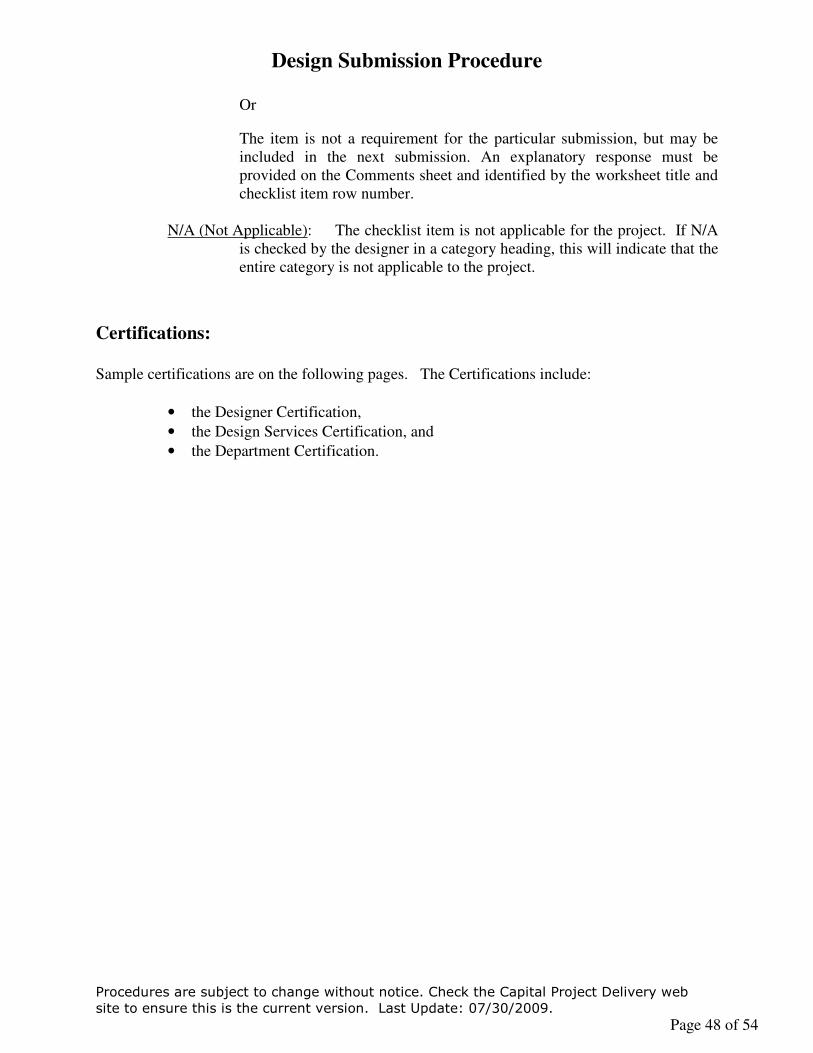
Design Submission Procedure
Procedures are subject to change without notice. Check the Capital Project Delivery web
site to ensure this is the current version. Last Update: 07/30/2009.
Page 48 of 54
Or
The item is not a requirement for the particular submission, but may be included in the next submission. An explanatory response must be provided on the Comments sheet and identified by the worksheet title and checklist item row number.
N/A (Not Applicable): The checklist item is not applicable for the project. If N/A
is checked by the designer in a category heading, this will indicate that the entire category is not applicable to the project.
Certifications: Sample certifications are on the following pages. The Certifications include:
• the Designer Certification,
• the Design Services Certification, and
• the Department Certification.

Design Submission Procedure
Procedures are subject to change without notice. Check the Capital Project Delivery web
site to ensure this is the current version. Last Update: 07/30/2009.
Page 49 of 54

Design Submission Procedure
Procedures are subject to change without notice. Check the Capital Project Delivery web
site to ensure this is the current version. Last Update: 07/30/2009.
Page 50 of 54

Design Submission Procedure
Procedures are subject to change without notice. Check the Capital Project Delivery web
site to ensure this is the current version. Last Update: 07/30/2009.
Page 51 of 54
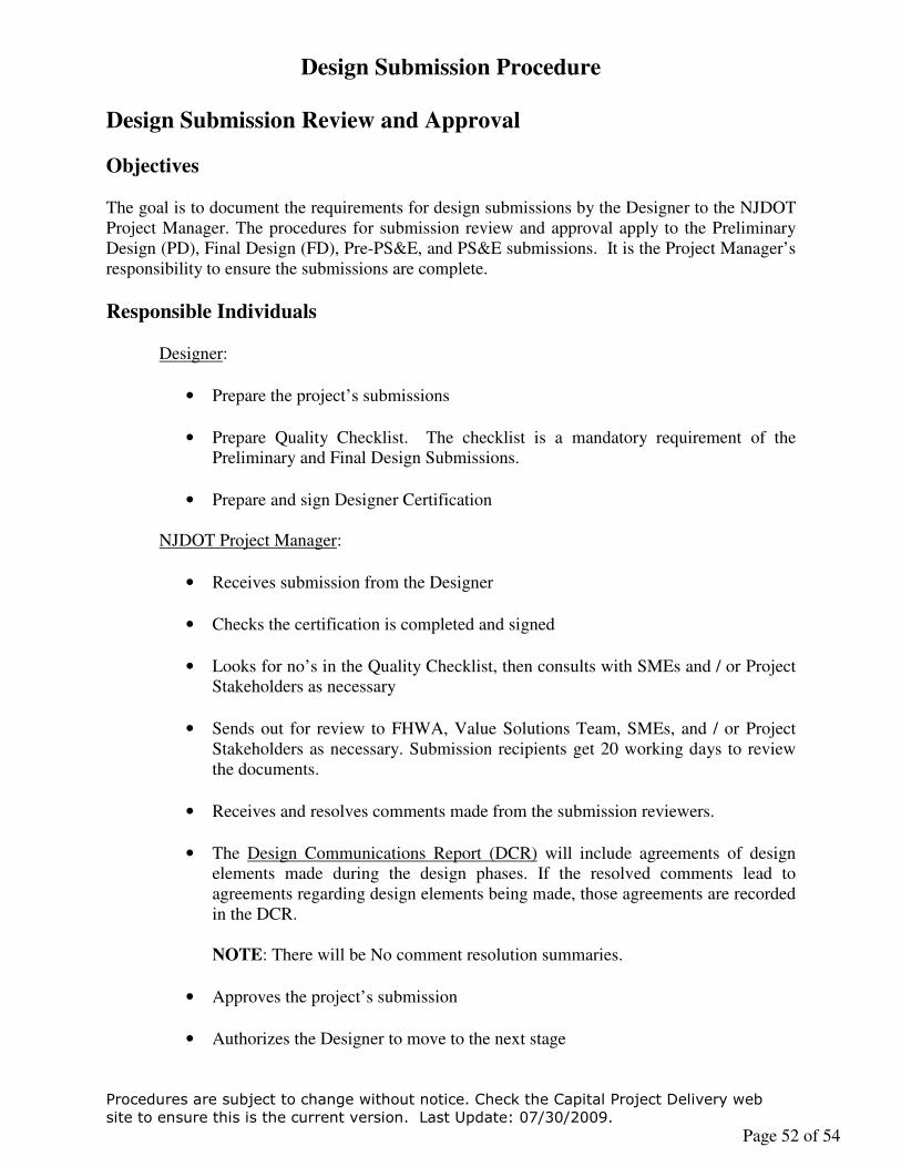
Design Submission Procedure
Procedures are subject to change without notice. Check the Capital Project Delivery web
site to ensure this is the current version. Last Update: 07/30/2009.
Page 52 of 54
Design Submission Review and Approval
Objectives
The goal is to document the requirements for design submissions by the Designer to the NJDOT Project Manager. The procedures for submission review and approval apply to the Preliminary Design (PD), Final Design (FD), Pre-PS&E, and PS&E submissions. It is the Project Manager’s responsibility to ensure the submissions are complete.
Responsible Individuals Designer:
• Prepare the project’s submissions
• Prepare Quality Checklist. The checklist is a mandatory requirement of the Preliminary and Final Design Submissions.
• Prepare and sign Designer Certification
NJDOT Project Manager:
• Receives submission from the Designer
• Checks the certification is completed and signed
• Looks for no’s in the Quality Checklist, then consults with SMEs and / or Project Stakeholders as necessary
• Sends out for review to FHWA, Value Solutions Team, SMEs, and / or Project Stakeholders as necessary. Submission recipients get 20 working days to review the documents.
• Receives and resolves comments made from the submission reviewers.
• The Design Communications Report (DCR) will include agreements of design elements made during the design phases. If the resolved comments lead to agreements regarding design elements being made, those agreements are recorded in the DCR.
NOTE: There will be No comment resolution summaries.
• Approves the project’s submission
• Authorizes the Designer to move to the next stage

Design Submission Procedure
Procedures are subject to change without notice. Check the Capital Project Delivery web
site to ensure this is the current version. Last Update: 07/30/2009.
Page 53 of 54
• Prepares the Department Certification at the Certified PS&E submission
Additional Controls: These controls are used at the discretion of the Project Manager.
• Risk Assessment should be assessed throughout the entire design phase. It is mandatory that the Risk Assessment be performed at the beginning of the project’s Preliminary Design.
a) The type of Quality controls will be dependent upon the following criteria:
- Project Scope
- Design Complexity
- Subject Matter Expert Review, as requested by the Project Manager
- Immediate environment around the project.
- Mitigating Circumstances and Issues (Other)
b) An independent review of the project can be included in the assessment.
SME’s and independent consultant / contractor will participate in the Risk Assessment. The SME’s and independent consultant / contractor will review the project plans.
c) Depending upon the Risk Assessment, a technical evaluation will be
performed and an Interim Submission will be generated documenting the evaluation's findings.
• As requested by the Project Manager or Designer, an Interim Submission will be generated. This review covers specific sections of the design during the Preliminary Design and Final Design process. The Interim Submission will provide technical rational and supporting documentation that will be used in the Preliminary Design Submission or the Final Design Submission. It will be available to any Project Stakeholder upon request from the Designer. An interim submission is reviewed and becomes a formal submission.
The Interim Submission will be reviewed by SME’s and / or independent consultant / contractor. Issues and concerns identified in the Interim Submission process will be resolved by the Designer and Project Manager. The Interim Submission will not be included in the Preliminary Design Submission and the Final Design Submission.

Design Submission Procedure
Procedures are subject to change without notice. Check the Capital Project Delivery web
site to ensure this is the current version. Last Update: 07/30/2009.
Page 54 of 54
Agreements to perform an interim submission, the content for an interim submission, and agreements resulting from the Interim Submission will be documented in the Design Communication Report.
• Additional procedures will be applied where needed. The Project Manager is responsible for identifying and implementing the procedures.