Embed Size (px)
Citation preview

Design study of advanced metallic structural integrated fan outlet guide vanes in civil jet engines Robert Gustavsson 2005
Preface This report is the written result of the compulsory master thesis work needed to gain a masters degree in mechanical engineering at Luleå University of Technology. The work corresponds to 20 university points and has been going on from August 2005 to December 2005. The thesis work has been performed under supervision of Peter Åström at the division of Computer Aided Design at Luleå University of Technology. The work has been carried out at Volvo Aero Corporation in Trollhättan, Sweden. I would like to thank my supervisor Dr. Peter Åström at Luleå University of Technology for his guidance and support and also my supervisors at Volvo Aero Corporation, Robert Reimers and Anders Sjunnesson, for their support throughout the thesis work. My thanks go also to people at Volvo Aero Corporation who have assisted me during this period. Trollhättan 2005-12-16 Robert Gustavsson
Design study of advanced metallic structural integrated fan outlet guide vanes in civil jet engines Robert Gustavsson 2005
Abstract Volvo Aero Corporation designs and manufactures components for civil jet engines. Design solutions for intermediate cases with integrated outlet guide vanes, which has the job to both carry load and direct the by pass air, are considered competitive for the future. Critical factors when designing integrated outlet guide vanes are weight, cost, structural stiffness, sound damping and operating life. Historically, the outlet guide vane (OGV) configuration has been solid vanes manufactured in materials like aluminium and titanium. A solid vane design will make the target weight for the outlet guide vanes to be exceeded, especially when engines are getting larger in diameter due to a desire to increase the by-pass flow. One way of reducing the weight of the OGV design is to make them hollow. The question is if a hollow vane will fulfil the mechanical requirements that an OGV configuration must withstand. Several concepts of OGV configurations have been developed and analyzed. Solid vane concepts have also been analyzed for reference purposes. The different concepts have also been evaluated with respect to material selection. Both the use of aluminium and titanium has been considered, since these are the most commonly used materials in outlet guide vanes. The chosen concept is made in titanium with a sheet thickness of 2 mm and has solid leading and trailing edge. The vane also has a polymer-foam core to increase the stiffness even further. During the analysis it became clear that if the outlet guide vanes are going to be made of aluminium, only solid vanes will be an option due to the low specific strength of aluminium. By making the vanes hollow in titanium, the weight can be decreased with 10% compared to making them solid in aluminium. The modal analysis showed that the vane with a foam core will have its first global eigenmode at 345 Hz, which is 20 Hz over the modal requirements. The analysis also showed that the configuration with a foam core has better strength properties and is more resistance to buckling than the configuration without a foam core.

Design study of advanced metallic structural integrated fan outlet guide vanes in civil jet engines Robert Gustavsson 2005
Table of contents 1. Introduction ................................................................................................................... 5 2. Nomenclature ................................................................................................................ 6 3. Background ................................................................................................................... 7
3.1. Intermediate case .................................................................................................. 7 3.1.1. Fan outlet guide vanes............................................................................... 8
4. Working procedure...................................................................................................... 10 5. Mechanical design requirements................................................................................. 11
5.1. HCF…................................................................................................................. 11 5.2. LCF……….. ....................................................................................................... 11 5.3. Limit load capability........................................................................................... 12 5.4. Ultimate load capability...................................................................................... 13 5.5. Hail ingestion...................................................................................................... 14
6. Possible design solutions............................................................................................. 15 6.1. The principle of sandwich structures.................................................................. 16
6.1.1. Core materials.......................................................................................... 16 7. Material ....................................................................................................................... 18
7.1. Comparison of materials..................................................................................... 18 7.1.1. Strength and stiffness .............................................................................. 18 7.1.2. Manufacturing ......................................................................................... 19 7.1.3. Corrosion and oxidation .......................................................................... 19 7.1.4. Creep ....................................................................................................... 19 7.1.5. Cost and availability................................................................................ 19 7.1.6. Fatigue ..................................................................................................... 19
7.2. Titanium and titanium alloys .............................................................................. 20 7.2.1. Titanium 6-4 ............................................................................................ 20
7.3. Aluminium and aluminium alloys ...................................................................... 20 7.3.1. Aluminium 2219...................................................................................... 21
7.4. ROHACELL® - PMI foams................................................................................ 21 8. Manufacturing ............................................................................................................. 22
8.1. Sheet metal forming............................................................................................ 23 8.2. Casting ................................................................................................................ 24 8.3. Welding............................................................................................................... 24
9. Analysis....................................................................................................................... 25 9.1. FE-models........................................................................................................... 27
9.1.1. Whole engine model................................................................................ 27 9.1.2. FE-model of the OGV ............................................................................. 29
10. Result........................................................................................................................... 31 10.1. Modal analysis .................................................................................................... 31 10.2. Impact ................................................................................................................. 34 10.3. WEM-analysis .................................................................................................... 37
10.3.1. Limit load conditions............................................................................... 37 10.3.2. Ultimate load conditions ......................................................................... 40
10.4. Buckling.............................................................................................................. 44 11. Conclusion................................................................................................................... 46

Design study of advanced metallic structural integrated fan outlet guide vanes in civil jet engines Robert Gustavsson 2005
12. Discussion ................................................................................................................... 48 13. Future work ................................................................................................................. 49 14. References ................................................................................................................... 50 APPENDIX
Title Number of pages 1 The target engine data 1 2 Material properties of ROHACELL® A 1 3 Material properties of ROHACELL® WF 1 4 Poisson ratio of ROHACELL® 1 5 Element thicknesses 1 6 List of computer files available at VAC 3

Design study of advanced metallic structural integrated fan outlet guide vanes in civil jet engines Robert Gustavsson 2005
5
1. Introduction
Volvo Aero develops and manufactures components for civil engines as well as for military jet engines. To extend their competitiveness in product development of big fan-structures, an investigation is made to examine the possibility to design these structures in lightweight materials, like composite materials. The possibility to integrate the aero dynamical function of the fan outlet guide vanes with the load carrying function is also evaluated, see Figure 1. These design changes together with the material changes has a potential to decrease the weight up to 40 %, while at the same time decrease the number of details in the engine. Another important environmental goal achieved by this new design is a reduction in noise cause by the jet engine. Volvo Aero’s main strategy in this matter is to make use of composite materials to achieve these goals.
Description of the design object
Several disciplines needs to be taken into account:Aerodynamics, engine performance (design and off-design), acoustics, cost of manufacturing, life cycle cost, weight, stiffness, strength, life, vibrations, flutter, forced excitation, bird strike resistance, erosion, corrosion etc.
σ
Figure 1. Description of the design object
The aim for this thesis work is to examine if there is any metallic material that can compete with composites in the matter of strength and weight. The work will incorporate:
• Investigation of possible materials • Different designs of integrated outlet guide vanes • Ranking and verification of the different design concepts with FE-analyses • Comparison of new designs with traditional designs in terms of design
specification necessities, weight and cost
Design study of advanced metallic structural integrated fan outlet guide vanes in civil jet engines Robert Gustavsson 2005
6
2. Nomenclature
To further enhance understanding, the following list of abbreviations has been stated. These abbreviations have been used throughout the report and are frequently used in the aviation industry. FBO Fan Blade Out FEA Finite Element Analysis FEM Finite Element Method HCF High Cycle Fatigue HPC High Pressure Compressor HPT High Pressure Turbine IMC Intermediate Case LBH Load Bearing House LCF Low Cycle Fatigue LPC Low Pressure Compressor LPT Low Pressure Turbine OGV Outlet Guide Vane TRF Turbine Rear Frame VAC Volvo Aero Corporation WEM Whole Engine Model

Design study of advanced metallic structural integrated fan outlet guide vanes in civil jet engines Robert Gustavsson 2005
7
3. Background
In order to understand how integrated outlet guide vanes affect the intermediate case it is important to understand the many aspects involved in designing an intermediate case (IMC). The role of the IMC in the engine and how it interacts with its surroundings is also important to understand. A target engine design is chosen to allow detailed requirements to be defined for the integrated guide vanes. The concept engine studied in this thesis work is supposed to replace today’s engine on short-haul aircrafts like the Boeing 737 and the Airbus 320. A more detailed description of the engine can be found in Appendix 1, and a schematic picture of a typical engine is found in Figure 2.
Figure 2. Components in a typical civil jet engine
3.1. Intermediate case The intermediate case structure includes the outer ring, integrated structural fan outlet guide vanes or load carrying struts, the mechanical connection of the outer ring to the core structure and the core structure. Figure 3 shows where the IMC is located in the engine. The intermediate case supports the high-pressure bearing structure and a low-pressure bearing support structure that includes the thrust bearings. The forces that act on the bearing generally occurs as a result of aircraft manoeuvres and forces are typically g-forces, gyro momentum and other flight induced loads. The IMC is a so-called “cold structure” since the operating temperature is considered to be fairly low compared to the parts downstream of the combustion chamber. This is also one of the reasons why the IMC usually is made of materials like titanium and aluminium.
Figure 3. Position of IMC in the GP7000 engine
Fan OGV IMC
LPT TRF
HPC
LPC
HPT

Design study of advanced metallic structural integrated fan outlet guide vanes in civil jet engines Robert Gustavsson 2005
8
3.1.1. Fan outlet guide vanes The air which passes through the fan will have a swirl angle exiting from the fan. Aerodynamically shaped guide vanes are used to redirect the flow from approximately a 35 degree swirl angle to axial flow. In the past, the fan outlet guide vanes were mounted as separate parts between the fan rotor and the intermediate case. The current trend is however to integrate the vanes into the load carrying IMC-structure. The difference between separately mounted outlet guide vane and integrated outlet guide vanes is illustrated in Figure 4. In some engines, like in the GE 90, the GP7000 and now in the latest GEnx-engine, the fan outlet guide vanes have been integrated in the IMC. Therefore, the shape with respect to aerodynamics of the structural by-pass struts must be considered. This can reduce the total weight and cost of the engine while at the same time decreasing the number of parts. By integrating the fan outlet guide vanes in the IMC-structure these can be eliminated as a separate design.
Figure 4. Separately mounted outlet guide vanes to the left and integrated outlet guide vanes to the right
There are plenty of design considerations to fulfil when designing integrated outlet guide vanes. Of great importance is how the OGV-profile is stacked in the structure i.e. how the cross sections are piled on top of each other. Because of the swirl angle imposed by the by the fan on the by pass air, and that this swirl angle varies radially decreasing outwards from the fan root of the OGV, the OGV top and bottom cross section will be different. How the OGV cross-sections are stacked will affect the mechanical performance of the OGV to a great extent.

Design study of advanced metallic structural integrated fan outlet guide vanes in civil jet engines Robert Gustavsson 2005
9
By designing the guide vane with an axially sweeped leading edge, see Figure 5, the wave front propagating from the fan will not hit the leading edge of the OGV simultaneously, thus reducing the amount of generated noise. The number of OGV:s are of great importance. A rule of thumb when designing rotor-stator components is to avoid that the number of stationary vanes is a multiple of the number of fan blades. Since the nacelle together with the pylon struts on the intermediate case makes up the two by-pass channels, it is necessary that these are located symmetrically in the intermediate case and therefore an even number of OGV:s are required. In this thesis a predefined vane profile was used together with a predefined aero-dynamical shape of the OGV:s. A design with 32 OGV:s was also selected.
Figure 5. IMC configuration with an integrated
axially sweeped OGV
x32

Design study of advanced metallic structural integrated fan outlet guide vanes in civil jet engines Robert Gustavsson 2005
10
4. Working procedure
The thesis work started with an introductory phase with the aim to understand the function of the outlet guide vane in an IMC-structure. It was also important to have an outline of how the outlet guide vane affects the engine in total. The project work was started with investigation of different configurations of integrated outlet guide vanes in different engines. A comparison between an IMC structure with only load carrying vanes and an IMC-structure with integrated outlet guide vanes was also studied. A thorough investigation of integrated OGV concepts was made to see what kind of demands a metallic OGV should withstand. This was made for example by studying design-, and load specifications for an IMC-structure with integrated outlet guide vanes. After this several ideas of different concepts came up and some of them were selected for further analysis. To analyse the different concepts several computer programs was used. First, it was necessary to learn the programs that are available at VAC, and it was decided that the pre-processing should be done in HyperMesh and the analysis in MSC Nastran and OptiStruct. To facilitate the work, different areas of investigations were created. These were made to find suitable materials that could be of interests, different manufacturing methods and what kind of analysis that had to be made to decide the OGV design. All this was investigated and is described in more detail in the next chapter in this report. Several FE-analyses were made and the results between the different concepts were compared. The results from these FE-analyses together with the manufacturing-, and cost aspects of each concept, a final concept was chosen and is presented later in this report.

Design study of advanced metallic structural integrated fan outlet guide vanes in civil jet engines Robert Gustavsson 2005
11
5. Mechanical design requirements
The IMC and the integrated outlet guide vanes needs to fulfil several design criteria, all found in the design specification for an IMC-structure. The OGV should be able to transfer loads from the IMC fan hub frame and to the forward engine mounts. Furthermore, the outlet guide vanes needs to withstand oxidation, corrosion as well as flight induced loads. The different design requirements are describe in the following. 5.1. HCF To achieve full engine life high cycle fatigue phenomena should be avoided by fulfilment of following criteria’s:
• No global eigenmode below 2:nd order of LPT • No local eigenmode below 5:th order of LPT • No local eigenmode in range of 1:st order of the fan blade passing frequency
±15%, based on LPT speed The resistance to HCF is in general determined by modal analysis and this would give the first global eigenmode of the OGV. The first eigenmode must be above 325 Hz to avoid the first five multipliers of the frequency caused by the low pressure rotor. The low pressure rotor is spinning at approximately 3900 revolutions per minute which is equivalent to a frequency of 65 Hz. The calculations can be seen below.
Hzf 6560
3900== 1:st eigenmode of LPT
Hzf 325565 =⋅= 5:th eigenmode of LPT
5.2. LCF A simplified flight cycle diagram, see Figure 6, is used to study low cycle fatigue, LCF. Fatigue occurs when a material is subjected to alternating stresses, over a long period of time. The most common type of loading cycle found in engineering applications is where the maximum stress (σmax) and minimum stress (σmin) are asymmetric (the curve is a sine wave) not equal and opposite. Since LCF calculations are time consuming and to simplify the work, LCF capability is evaluated by ensuring that the maximum stresses during a limit load case does not exceed 50% of the yield strength.

Design study of advanced metallic structural integrated fan outlet guide vanes in civil jet engines Robert Gustavsson 2005
12
Figure 6. Typical engine flight cycle 5.3. Limit load capability The limit load cases are to be considered as typical loads during a flight cycle and in ground handling of the engine. Examples of these load sets are when the engine runs at max thrust and decelerating while landing (thrust reverse). During these situations, specified deformation limits must not be exceeded. The IMC should withstand these limit loads without any permanent deformation, meaning that the local stress levels must not be above the yield strength of the material. The limit load cases are:
1. Take of rotation: Max thrust, 2g downward, and lateral gyroscopic forces 2. Arbitrary Gust: Max thrust, 5g downward and 1g laterally 3. Thrust reverse: Max revere thrust, 1g downward
It is not only the thrust force that is imposed on the OGV during take-off but also gyroscopic forces due to the rotating engine shaft. When the shaft is spinning, gyroscopic effects will create an additional resultant force acting in the radial direction. Figure 7 illustrates this phenomenon when a moment around x and y will create an additional force, P, acting in the z-direction. This is however not the most severe load case which the outlet guide vanes are subjected to. An even more severe load case is produced in the landing sequence when the breaks on the aircraft not are efficient enough so a need for additional method for bringing the aircraft to stop is required. Additional braking force is accomplished by reversing the exhaust gas stream and thereby using the engines power for decelerating. The use of thrust reverse has a huge influence on the aircrafts landing distance. Also the arbitrary gust load case is of more interest compared to the other two since this will create the worst limit load case.
Taxi: Ground
Max Thrust (Climb)
Cruise
Descent
Thrust Reverse
Taxi: Ground Idle

Design study of advanced metallic structural integrated fan outlet guide vanes in civil jet engines Robert Gustavsson 2005
13
Figure 7. Forces created by the spinning moments
of the engine during Take off 5.4. Ultimate load capability In certain situations, abnormal loads may act on the IMC-structure. These loads are defined as ultimate load cases. These extreme load cases must be considered when designing the IMC and examples of ultimate load cases are:
4. Emergency landing 9g in axial direction 2a. Arbitrary Gust x 1.5 1.5 x (Max thrust, 5g downward and 1g laterally) 3a. Thrust reverse x 1.5 1.5 x (Max revere thrust, 1g downward) 5. Rotation imbalance Rotating imbalance of 600 kN at fan CofG
Fan blade out is considered as an ultimate load case. When a fan blade for some reason escapes from the fan root and hits the fan case a large turning momentum is induced on the fan case and on the IMC. The fan blade out scenario has been analysed by imposing forces represent the unbalance created of the fan rotor. This force will approximately be 600 kN at the fan centre of gravity. After a fan blade out accident, the component should have sufficient residual capability to withstand windmilling operation for 2,5h. During these ultimate load situations, plasticity is allowed only at small areas of the component but the ultimate tensile strength can never be exceeded anywhere in the structure. This stress criteria is more describe under chapter 0 where he result of the FBO-analysis is presented. A buckling analysis must also be made to evaluating the sheet thickness of the OGV. The buckling requirement for this kind of model is 3. Therefore a buckling load factor of 3 must be obtained during the buckling analysis with a buckling force of 100 kN, since this force is estimated to rise during a FBO.

Design study of advanced metallic structural integrated fan outlet guide vanes in civil jet engines Robert Gustavsson 2005
14
5.5. Hail ingestion The engine is subjected to two hail ingestion scenarios and should withstand ingestion of both 25mm and 50 mm hailstones. The aim is to investigate if rupture will occur in the structure during an impact load. The 25 mm hail is considered to produce a limit load and should hence not cause any plasticity in the structure while the 50 mm hailstone is considered to give rise to an ultimate load case where small amounts of local plasticity can be tolerated. To investigate this, a transient analysis must be done with forces for each of the concepts, material, sheet thickness and diameter of the ice hails. These forces must be calculated and have been received from Anders Sjunnesson at VAC. These forces have been calculated by using plate theory and are comparing the ratio between maximum strains with allowable strain.

Design study of advanced metallic structural integrated fan outlet guide vanes in civil jet engines Robert Gustavsson 2005
15
6. Possible design solutions
Historically, the OGV configuration has consisted of solid vanes manufactured in materials like aluminium and titanium. However, with a solid vane solution, the total weight for the outlet guide vanes will be too high, especially when the engines are getting larger in diameter. The trend towards large-diameter jet engines is driven by the fact that a larger diameter increases the by-pass flow in the jet engine, which is a desirable characteristic. One solution to reduce the weight of the OGV design is thus to make the vanes hollow. Making the OGV:s hollow will however cause some manufacturing difficulties. Traditionally, solid vanes have been casted but since the configuration will bee too complicated for a one-piece casting this is not an option for hollow vanes. Therefore a fabrication manufacturing technique must be developed to make hollow vanes a reality. Different OGV design concepts have been developed. If a simple hollow vane does not fulfil the mechanical requirements that an OGV must withstand, a concept with a foam core has also been suggested. The reason to add a foam core is that the core will contribute to the configuration by adding extra stiffness and little extra weight. Three different concepts have been analysed:
1. Solid vanes 2. Sheet metal vanes, with a defined thickness combined with a solid leading- and
trailing edge 3. Sheet metal vanes, with a defined thickness combined with a solid leading- and
trailing edge and a foam core
Figure 8. Vane crossection with a solid leading and trailing edge
A vane filled with a polymer foam will form a sandwich structure. Sandwich structures generally have a high stiffness-to-weight ratio. The combination of high stiffness and low weight is desirable due to fuel economy reasons, environmental issues and potential for higher profits while at the same time maintaining component performance. A more detailed description of sandwich structures mechanics and related works is presented in chapter 6.1.

Design study of advanced metallic structural integrated fan outlet guide vanes in civil jet engines Robert Gustavsson 2005
16
6.1. The principle of sandwich structures Sandwich structures consist of thin, high-density outer and inner facings, and a thick, low-density core. They overcome the problem of increasing weight with increasing material thickness and are thus particularly useful in aerospace applications. In sandwich structures the core sustains the shear load, while the faces take the compressive and tensile bending loads. Typical face materials include aluminium alloys, fibre-reinforced plastics, titanium and steel. Sandwich panels are found in a wide variety of applications, e.g. in aircrafts wings, fuselage and in various part in the aircraft engine such as for instance in fan casings. A key design criterion for high-performance structural component parts in aerospace applications is the stiffness-to-weight ratio. The performance of sandwich structures depends primarily upon the surface facings and the distance between them. A large distance between the surfaces faces give a large geometrical moment of inertia, thus leading to high bending stiffness. The behaviour of a sandwich structure under bending can be seen in Figure 9.
Figure 9. A sandwich structure under bending load 6.1.1. Core materials Structurally, the core serves two functions. First, it separates the faces and resists deformations perpendicular to the face plane. Secondly, it provides a certain degree of shear rigidity along planes that are perpendicular to the faces. Various materials and material structures are utilized for cores e.g. foamed polymers. Another frequently used core structure is the honeycomb structure – thin foils that have been formed into interlocking hexagonal cells, with axes oriented perpendicular to the face planes. The material of the honeycomb structure may be similar to the face material. Figure 10 shows an aluminium honeycomb core and a foam-core.
Bending stiffness: By = Eskin * h2 * t/2 Assumption: Eskin >> Ecore
h = hcore t/h < ¼

Design study of advanced metallic structural integrated fan outlet guide vanes in civil jet engines Robert Gustavsson 2005
17
While the most important thing with the surface skins in combination with the core material is the potential for high stiffness-to-weight ratio. Aluminium honeycomb core made of aluminium for example have a great potential for performance with regard to weight due to that a high compression modulus can be obtained with a minimum of material. Honeycomb core materials have established themselves firmly in aerospace applications and some typical structural components are leading edges on the wing and empennage, landing gear doors and other access doors. But honeycomb structures are costly which is why polymer foams are of interest. Polymer foam has a lower compression modulus compared to a honeycomb structure but comparable is shear strength. These polymer foams meet the requirements in aircraft design and are widely used as core materials for demanding sandwich structures such as landing gear doors, pressure bulkheads, stringer stiffened panels, flap vanes, engine cowling doors and flight control surfaces.
Figure 10. Top left: A honeycomb structure with panels. Bottom left: The honeycomb core. Right: A structure with foam core
Design study of advanced metallic structural integrated fan outlet guide vanes in civil jet engines Robert Gustavsson 2005
18
7. Material
Aerospace industry material demands include improved toughness, lower density, increased resistance to fatigue and corrosion. The boundaries of what materials can withstand are being constantly extended as manufacturers strive to improve the performance of the next generation of aircrafts. Titanium and aluminium are two of the key materials facing these demands. These material alloys are used in a large number of aerospace applications, from lightly loaded components through to load carrying structures in aircrafts and aircraft engines. The choice of material for the OGV involves a wide range of considerations including manufacturing processes, material costs, and availability. Another important factor when selecting the material is if there is any previous experience of the material in question. The two different alloys that have been selected in this thesis work during the analysis can be seen in Table 1. 7.1. Comparison of materials Recent attention has been given to alloys of aluminium, titanium and other low-density metals as engineering materials for transportation. Reduced weight has a large effect on reduced fuel consumption which contributes to the notion of the next generation of environmental friendly jet engines. An important characteristic of these materials is the specific strength, which is quantified by the tensile strength – density ratio. Even though an alloy of one of these low-density metals may have a tensile strength that is lower in comparison to a more dense material such as steel, on a weight basis, the low-density material will be able to sustain a larger load. When comparing the materials, the following properties were investigated:
• Strength and stiffness (E-modulus) • Manufacturability • Corrosion and oxidation • Creep • Cost and availability • Fatigue resistance
7.1.1. Strength and stiffness Mechanical properties such as yield- and ultimate strength have to be high since the IMC-structure is one of the main load carrying structures in the engine. Stiffness describes a material resistance to deform and is measured in terms of Young’s modulus. Young’s modulus also has a thermal dependence and decreases with increasing temperatures.

Design study of advanced metallic structural integrated fan outlet guide vanes in civil jet engines Robert Gustavsson 2005
19
7.1.2. Manufacturing When selecting material for a design, the manufacturing properties of the chosen material are of great importance. It is important that the material can be processed by the most common methods such as by forging, casting and welding. If not, the result is often a more complex and expensive manufacturing. 7.1.3. Corrosion and oxidation Oxidation is when metals react with oxygen. The process is also known as scaling or dry corrosion. Most metals will react with oxygen at room temperature. The rate of reaction at room temperature is low and the oxide layer that forms on the surface acts as a barrier to further oxidation. 7.1.4. Creep Creep is a diffusive process where the material permanently strains as a function of stress, time and temperature. The creep process typically begins when the absolute temperature is greater than 0.3 - 0.5 of the melting temperature. The general shape of creep curves is consistent across metals, ceramic and polymers. To avoid failure in the engine, selected materials must have a high resistance to creep at the operating temperature. 7.1.5. Cost and availability The cost benefit analysis is typically performed downstream of the concept development stage of product development i.e. when the material decision is finalized. Because new materials are usually more complex and often require closer control and even new technologies for their processing, components made from such materials are more expensive. Common bulk materials, e.g. steel, are typically much less expensive than materials intended for special applications e.g. titanium and super alloys. 7.1.6. Fatigue Many failures in mechanical assemblies can be deduced to as fatigue failure. Fatigue occurs when a material is subjected to alternating stresses, over a long period of time. Low cycle fatigue in this specific consideration is one whole flight cycle with a number of load cases, and high cycle fatigue refers to the loading iterations that occur during the flight cycle.

Design study of advanced metallic structural integrated fan outlet guide vanes in civil jet engines Robert Gustavsson 2005
20
7.2. Titanium and titanium alloys Titanium and titanium alloys are relatively new engineering materials that possess an extraordinary combination of properties. The pure metal has relatively low density, high melting point and low elastic modulus. Some titanium alloys are of extremely high strength, have high ductility and can be easily forged and machined. These unique combinations of mechanical and physical properties together with the corrosion resistance are the reason why titanium alloys have become desirable for the demanding aerospace industry. Titanium has superior structural efficiency in high strength compared to structural steels and aluminum alloys, especially as service temperatures increase. This permits optimized alloy selection which can be tailored for a critical component based on whether it is controlled by strength and fatigue, or toughness and crack growth. Titanium alloys exhibit a low modulus of elasticity, roughly half that of steels and nickel alloys. Titanium has relatively low density, about 56% of that of steel and half of that of nickel and copper alloys. Together with high strength, this contributes too much lighter and/or smaller components for both static and dynamic structures, like aerospace engines and airframes. 7.2.1. Titanium 6-4 The most widely used titanium alloy is the Ti-6Al-4V alpha-beta alloy. This alloy is well understood and is also very tolerant on variations in fabrication operations, despite its relatively poor room-temperature shaping and forming characteristics compared to steel and aluminium. Alloy Ti-6Al-4V, which has limited section size hardenability, is most commonly used in the annealed condition. Another important factor when selecting this alloy was that there is an earlier experience working with this alloy at VAC. The combination of high strength-to-weight ratio, excellent mechanical properties, and corrosion resistance makes titanium 6-4 the best material choice for many critical applications. The material properties of titanium 6-4 can be seen in Table 1. 7.3. Aluminium and aluminium alloys Aluminium is a lightweight, corrosion resistant structural material that can be strengthened through alloying and, depending on composition, further strengthened by heat treatment and/or cold working. Among its advantages are: low density (2700 kg/m3) compared to steel (7900 kg/m3), good corrosion resistance and easy to fabricate. The mechanical strength of aluminium may be enhanced by cold working and by alloying. Principal alloying elements include copper, magnesium, silicon and zinc. A generation of new aluminium-lithium alloys have been developed recently for use by the aircraft and aerospace industries. These materials have relatively low densities (between 2500 kg/m3 and 2600 kg/m3), high specific modulus of elasticity and excellent fatigue and low-temperature toughness properties. However, these materials are more

Design study of advanced metallic structural integrated fan outlet guide vanes in civil jet engines Robert Gustavsson 2005
21
costly to manufacture than conventional aluminium alloys since special processing techniques are required as a result of lithium’s chemical reactivity. 7.3.1. Aluminium 2219 Aluminium 2219 is a forging alloy and is one of the most widely used alloys in the 2000 series and is being used in the aerospace industry for many different of applications. This standard structural alloy, one of the most popular for medium and high strength requirements, has good toughness characteristics. The 2219-alloy has also excellent corrosion resistance to atmospheric conditions. Aluminium 2219 is easily welded and joined by various commercial methods. The material properties of aluminium 2219 can be seen in Table 1. Table 1. Material data for the OGV design
7.4. ROHACELL® - PMI foams ROHACELL® is a polymethacrylimide- (PMI-) hard foam, which is used as a core material in sandwich structures. It has appropriate mechanical and thermal properties for aerospace use compared to other foams. These foams are used in a variety of applications, ranging from mobility to sports and recreational equipment, medical technology and communications to components for aerospace use. The classical requirement to be met in aircraft design is low weight combined with optimum mechanical properties. ROHACELL® is widely used as core material for demanding sandwich structures, such as for landing gear doors. This PMI-foam shows outstanding strength-to-weight ratio even at elevated temperatures and excellent fatigue behavior. Due to the good resistance to compressive creep, it can be used under high temperature and high pressure conditions. ROHACELL® A (= Aircraft grade) is a plastic foam based on PMI. The field of application for this foam is aircraft construction. The heat distortion temperature is 180°C, densities range from 30 to 75 kg/m3 and the product has an elastic modulus ranging from 36 to 160 MPa. A more detailed table of the mechanical properties can be seen in Appendix 2. ROHACELL® WF (= grade with increased heat distortion resistance) is a plastic foam based on PMI. ROHACELL® WF serves as a core material in advanced sandwich components used in aircraft and aerospace construction and is easy to shape. The heat distortion temperature is 205°C, densities range from 52 to 200 kg/m3 and the elastic modulus range from 75 to 350 MPa. A more detailed table of the mechanical properties can be seen in Appendix 3.
Yield strength [MPa]
Ultimate tensile strength
[MPa]
Youngs modulus [MPa]
Density [kg/m3]
Poissons ratio
Specific strength
Specific stiffness
Titanium 6-4 880 950 113.8 4430 0.34 0.20 0.257 Aluminium 2219 395 475 72 2840 0.33 0.14 0.254

Design study of advanced metallic structural integrated fan outlet guide vanes in civil jet engines Robert Gustavsson 2005
22
8. Manufacturing
Casting is almost always used to manufacture today’s modern intermediate cases including the outlet guide vanes. Since the price for big castings is very high, a fabricated intermediate case concept has been developed. Fabrication means that smaller pieces are manufactured and then assembled to a complete OGV. This means that the manufacturing cost will be less since smaller castings can be performed by a larger number of manufacturers. That’s one of the reasons why a fabricated concept of an OGV has been developed in the thesis work. The OGV geometry is made by two formed plates in sheet metal with a solid leading and trailing edge, see Figure 11. The solid parts are casted, and since these parts are small, the process of casting them is relatively simple. The two sheet plates are then welded on to the leading and trailing edge. The two stubs on the inner- and outer ring that the vanes are welded on are also casted. There are many advantages of casting the stubs, of which one is the possibility to obtain tight tolerances between the vane and the outer ring. This will eliminate sharp edges leading to stress concentrations. The fillet between the vane and the outer ring is also very easy to obtain when casting the stubs. The manufacturing techniques presented above are described in detail later in this chapter as is also special considerations regarding machining of different materials like titanium and aluminium. There are different ways of assembling the vanes to the fan hub frame and the outer ring. Combinations of titanium and aluminium cannot be welded which means configurations with this combination of materials must be assembled by screws. To fulfil the requirements of mechanical loads, temperature loads, LCF and so on, a closer calculation must be done to investigate the influence of the number of holes in the front and rear flange of the OGV. The screws should be made out of a material with high structural stiffness and strength. Super alloys, such as Inconell 718, are typically used in this type of applications.
Figure 11. Shows the manufacturing techniques and how the different parts are welded together
Solid leading edge: Casting
Solid trailing edge: Casting
Sheet plate: Forming
Weld
Weld
Weld
Weld

Design study of advanced metallic structural integrated fan outlet guide vanes in civil jet engines Robert Gustavsson 2005
23
8.1. Sheet metal forming The formability of a sheet metal is a measure of the metal’s ability adapt to a certain imposed geometry. The formability is a complex issue and it is dependent on the material properties of the sheet metal and therefore it varies when comparing the formability between titanium and aluminium. Titanium is more difficult to form compared to steel and aluminium. Titanium possesses certain unique characteristics that affect formability, and these must be considered when undertaking titanium forming operations. Titanium has a relatively low Young’s modulus, about half that of stainless steel. The low Young’s modulus together with its high yield strength results in greater spring-back during forming and requires compensation either during bending or by post-bend treatment. Springback generally depends on the relationship between the size of the bend radii and the sheet thickness. Titanium and titanium alloys can be cold formed and hot formed in standard forming equipment using techniques similar to those of stainless steels. The room temperature ductility of titanium and its alloys is generally less than that of common structural metals including stainless steels. This necessitates more generous bend radii and less allowance for stretch formability when cold forming. Before a titanium sheet is formed, it should be clean and free of surface defects such as nicks, scratches or grinding marks. All scratches deeper than the finish produced by 180-grit emery should be removed by sanding. A radius should be created on sharp edges to prevent edge cracking. Surface oxides can lead to cracking during cold forming and should be removed by mechanical or chemical methods. Oil, fingerprints, dirt and chemicals should be removed before heating, since the salt in these pollutions could cause so-called hot-salt-cracking on the surface during heating. Aluminium is much easier to form compared to titanium. Aluminium forming is used extensively in the automotive industry and can be used to manufacture aluminium sheet plates in the OGV structure.

Design study of advanced metallic structural integrated fan outlet guide vanes in civil jet engines Robert Gustavsson 2005
24
8.2. Casting Today, casting continues to be the most widely used method for structural vane manufacturing. Technical advances have been made, but the principle remains the same: molten metal is poured into a mould to duplicate a desired geometric shape. Investment casting, often called lost wax casting, is regarded as a precision casting process to fabricate near-net-shaped metal parts from almost any alloy. This casting technique is used in the production of complex, often thin-walled, castings. The casting method is one way of casting the complex shape of the OGV and works for both titanium and aluminium. One disadvantage with casting alloys is that they exhibit poor material properties (e.g. lower yield strength) compared to forged alloys and sheet metal. The investment casting process begins with fabrication of a pattern with the same basic geometrical shape as the finished cast part. Patterns are normally made of investment casting wax that is injected into a metal wax injection die. Fabricating the injection die is much expensive and can require several months of lead time. Once a wax pattern is produced it is then dipped in ceramic slurry, covered with sand stucco and are then allowed to dry. Once the ceramic has dried, the removal of the wax begins and after that only the ceramic mould remains. The mould is then preheated to a specific temperature and filled with molten metal, and finally creating the metal casting. Once the casting has cooled sufficiently, the mould shell is then removed away from the casting. 8.3. Welding Commercially pure titanium and most titanium alloys can be welded by procedures and equipment used in welding of stainless steel and aluminium. Because of the high reactivity of titanium and titanium alloys at temperatures above 550°C, additional precautions must be applied to shield the weldment from contact with air. Also, the titanium base metal and the filler metal must be clean to avoid contamination during welding. Unalloyed titanium and all alpha titanium alloys are weldable. Also the alpha-beta alloy Ti-6A-4V is weldable. Welding severely affect the material properties. Alloy composition, welding procedure, and subsequent heat treatment are highly important in determining the final properties of welded joints. Gas-tungsten arc welding (TIG) is the most widely used welding process for joining titanium and titanium alloys except for parts with a thick weld cross section. Electron-beam welding (EB) is used in the aircraft- and aerospace industries for producing high-quality welds in titanium and titanium alloy plates. Because the welding is performed in a vacuum atmosphere, low contamination of the weldment is achieved.

Design study of advanced metallic structural integrated fan outlet guide vanes in civil jet engines Robert Gustavsson 2005
25
9. Analysis
Several analyses were made to decide the OGV-configuration. Dimensions and thickness of the different parts of the outlet guide vane were altered between individual simulation runs. A number of analyses had to be made before a final configuration could be selected. The configurations were investigated using titanium and aluminium. A concept with a combination of titanium and aluminium was also investigated since during the analysis it became clear that some vanes were exposed to more stress than others. That’s how the idea of use a material with better strength properties at these vanes, see Figure 12. Optimizing material usage by using different materials at different locations will reduce the manufacturing cost since aluminium is cheaper to use and has better machinability properties.
Titanium*
Titanium** Figure 12. Configuration with a combination of titanium and aluminium
5 vanes at top engine mount, * 3 vanes at gearbox, ** 24 other vanes, ***
Aluminium*** Aluminium***

Design study of advanced metallic structural integrated fan outlet guide vanes in civil jet engines Robert Gustavsson 2005
26
The weight of the different configurations can be seen in Table 2. Notice that this weight comparison takes no concern of the different strength/stiffness properties that each configuration and material have. Table 2. Weight of different vane configuration
*) Vane without foam core
Sheet thickness [mm]
Weight, 1 vane [kg]
Weight, 32 vanes [kg]
Titanium 6-4 2* 1.86 59.52 2 1.88 60.16 2.5* 2.19 70.08 2.5 2.21 70.72 3.0* 2.53 80.96 3.0 2.54 81.28 solid 3.22 103.04 Aluminium 2219 2* 1.15 36.80 2 1.16 37.12 2.5* 1.35 43.20 2.5 1.37 43.84 3.0* 1.55 49.60 3.0 1.57 50.24 solid 2.10 67.20

Design study of advanced metallic structural integrated fan outlet guide vanes in civil jet engines Robert Gustavsson 2005
27
9.1. FE-models Different techniques have been used to perform the analyses. For the stiffness analysis a WEM has been used while in the other three, only a sector including one OGV with a small part of the outer ring, inner ring and hub was analysed. 9.1.1. Whole engine model To evaluate and analyse the behaviour of the intermediate case and the integrated outlet guide vanes in the jet engine, a whole engine model (WEM) was used. This WEM has been developed at VAC and is being used in other similar projects at VAC. The only modification that had to be done was the outlet guide vanes in the IMC-structure. On this model different load cases were analysed that would simulate different flight conditions, events during the flight cycle or other events that’s affects the intermediate case and the integrated outlet guide vanes. A whole engine model may be used to perform linear and non-linear, static and dynamic analyses in order to provide information of stresses and displacements for further detail design and analysis. The different parts of the WEM are mostly modelled with shell-, beams- and rigid elements, see Figure 13. The surrounding structure transfer loads and momentums onto the IMC and the outlet guide vanes during a WEM analysis.
Figure 13. Whole engine model

Design study of advanced metallic structural integrated fan outlet guide vanes in civil jet engines Robert Gustavsson 2005
28
9.1.1.1. Constraints Different kinds of constraints were used when analysing the whole engine model to simulate the engine mounts. The IMC contains two different types of engine mounts, two mounts in the rear wall of the inner ring (4, 5) and two mounts on the outer ring on the top of the IMC (1, 2). Two engine mounts is also placed on the outer ring of the turbine rear frame (TRF) in the end of the engine (7, 8). The two engine mounts (1, 2) that are located on the top of the outer ring of the IMC, see Figure 14, has been modelled by two rod-elements attached to an external node. The two thrust lugs (4, 5) that are located on the back wall of the torsion box, see Figure 14, have been modelled by two thrust links which is connected to the pylon under the wing. The thrust links are simulated by two rod-elements and are connected to an external node for each thrust link. Number 3 is a rod element and is just a safe precaution if the other two (1, 2) will be disabled. The rear engine mounts, number 6, 7 and 8 in Figure 14, are located on the top of the outer ring of the TRF. The engine mounts were simulated by a beam element in 7 and a rod element in 8, since a rod element doesn’t have any rotational degrees of freedom. This will prevent rigid body rotations. Number 6 is a rod element and is just a safe precaution if the other two (7, 8) will be disabled.
Figure 14. Locations of the constraints
1 23
45 6
7
8

Design study of advanced metallic structural integrated fan outlet guide vanes in civil jet engines Robert Gustavsson 2005
29
9.1.2. FE-model of the OGV A FE-model with combined shell- and solid elements has been used. Solid elements are used in the leading and trailing edge and in the middle of the vane to symbolize the polymer foam. Shell elements are used for the sheet plate between the leading and trailing edge, see Figure 15. The light blue symbolize the polymer foam, green colour the sheet plate, orange the solid leading edge and red the solid trailing edge.
Figure 15. FE-model of the vane Simplifications have been made when creating the mesh of the OGV. The connections between the solid parts to the sheet, in the leading and trailing edge, overlap two elements. This will take care of the rotational degrees of freedom between the solid and shell elements and will provide a good connection between the shell and the solid elements. The connection is made so that the shell- and solid element are sharing same nodes. The technique will cause material to be overlapping since the shell elements are being offsets inward toward the solid elements. The vane model is then placed into the intermediate case model, see Figure 16, which in turn is used within the whole engine model.
Figure 16. FE-model of the IMC with integrated OGV:s
Foam
Solid leading edge
Solid trailing edge
Sheet plates

Design study of advanced metallic structural integrated fan outlet guide vanes in civil jet engines Robert Gustavsson 2005
30
Figure 17. FE-models of a sector used in the modal, buckling and impact analysis. The left sector is a hollow vane and the right sector is the a solid vane
The FE-model of the solid vane is different compared to the one representing the hollow vane, see figure 17. The solid vane is modeled with shell elements with different thickness in the axial direction. Variable thickness will give get a more accurate result when analyzing solid vanes. The different element thicknesses can be seen in Table 14 in Appendix 5. The FE-model of the hollow vane is similar to the one shown in Figure 15 except for the solid elements between the shell elements that symbolize the foam. The model consists therefore only by the solid elements symbolize the solid leading and trailing edge and the shell elements the sheet metal. The element length became approximately 10x10 mm. This element size may be to big considering the vane profile. It is desirable to have a least six solid elements through the thickness of the FE-model. But since the vane profile is very thin and long this will lead to a large amount of elements which leads to an increase in analyze time and computer resources. Therefore only two elements through thickness were modelled. This will lead to that the stiffness will be to high in the solid leading and trailing parts. Also the foam which is modelled with solid elements is to stiff. This little extra stiffness was accepted since the foam has a very low density and Young’s modulus compared to titanium and aluminium and will not affect the analyse result to a great extent.
Design study of advanced metallic structural integrated fan outlet guide vanes in civil jet engines Robert Gustavsson 2005
31
10. Result
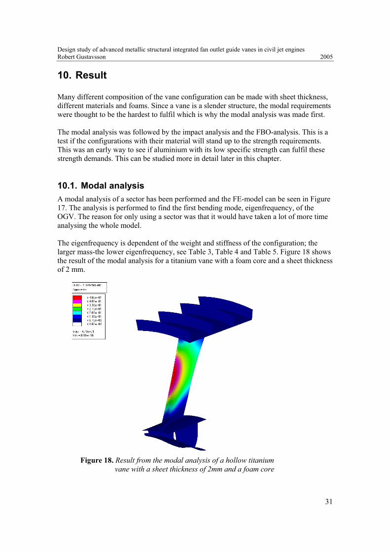
Many different composition of the vane configuration can be made with sheet thickness, different materials and foams. Since a vane is a slender structure, the modal requirements were thought to be the hardest to fulfil which is why the modal analysis was made first. The modal analysis was followed by the impact analysis and the FBO-analysis. This is a test if the configurations with their material will stand up to the strength requirements. This was an early way to see if aluminium with its low specific strength can fulfil these strength demands. This can be studied more in detail later in this chapter. 10.1. Modal analysis A modal analysis of a sector has been performed and the FE-model can be seen in Figure 17. The analysis is performed to find the first bending mode, eigenfrequency, of the OGV. The reason for only using a sector was that it would have taken a lot of more time analysing the whole model. The eigenfrequency is dependent of the weight and stiffness of the configuration; the larger mass-the lower eigenfrequency, see Table 3, Table 4 and Table 5. Figure 18 shows the result of the modal analysis for a titanium vane with a foam core and a sheet thickness of 2 mm.
Figure 18. Result from the modal analysis of a hollow titanium
vane with a sheet thickness of 2mm and a foam core

Design study of advanced metallic structural integrated fan outlet guide vanes in civil jet engines Robert Gustavsson 2005
32
Table 3. Results from the modal analysis of solid vanes Weight [kg] Mode 1 [Hz] Mode 2 [Hz] Titanium 6-4 3.22 303 423 Aluminium 2219 2.10 325 447 Table 4. Results from the modal analysis of hollow vanes with solid leading and trailing
edge Sheet thickness
[mm] Weight
[kg] Mode 1
[Hz] Mode 2
[Hz] Titanium 6-4 2.0 1.86 330 410 2.5 2.19 334 433 3.0 2.53 335 451 Aluminium 2219 2.0 1.15 359 435 2.5 1.35 363 461 3.0 1.55 365 483 Table 5. Results from the modal analysis of hollow vanes with solid leading and trailing
edge and a foam core Sheet thickness
[mm] Weight
[kg] Mode 1
[Hz] Mode 2
[Hz] Titanium 6-4 2.0 1.88 345 437 2.5 2.21 344 454 3.0 2.54 343 471 Aluminium 2219 2.0 1.16 375 468 2.5 1.37 374 485 3.0 1.57 373 502 Configuration 3 has been analysed with ROHACELL 31A which is the foam with lowest density and Young’s modulus among the different ROHACELL foams. The result shows that almost every configuration will satisfy the demand to have their first global eigenmode over 325 Hz. Solid vanes will merely fulfil this limit of 325 Hz except for the solid aluminium vane which is dangerously close to the limit. The result also showed that the third configuration, with a foam core, got a higher frequency than the second configuration with no foam core. The reason for this is the high stiffness-to-weight ratio supplied by a sandwich structure. To obtain comparable eigenfrequencies without a foam core, the sheet thickness must be increased considerably which affects the weight of the OGV negatively.

Design study of advanced metallic structural integrated fan outlet guide vanes in civil jet engines Robert Gustavsson 2005
33
One way to increase the eigenfrequency for solid titanium vanes is to increase the thickness of the vane profile since this will increase the stiffness of the structure. Several modal analyses showed that the thickness of each lay up of the FE-model must be approximately 35% thicker to fulfil the requirements. Increasing vane profile thickness will result in a larger mass. The weight of a 35% thicker vane will be 4.35 kg which is 1.13 kg heavier and results in a first global eigenmode at 327 Hz, see Table 6. Table 6. New profile-thickness of a solid titanium vane
Lay up Original thickness [mm]
35% increase in thickness [mm]
1 4.25 5.74 2 5.75 7.76 3 7.75 10.46 4 10.25 13.84 5 10.75 14.51 6 11.25 15.19 7 10.75 14.51 8 10.25 13.84 9 8.75 11.81 10 7.75 10.46 11 6.75 9.11 12 4.75 6.41 13 3.25 4.39 14 2.25 3.04
Original weight [kg]
New weight [kg]
Weight, 1 vane 3.22 4.35 Weight, 32 vanes 103 139
Original first eigenmode [Hz]
New first eigenmode [Hz]
Frequency 303 327

Design study of advanced metallic structural integrated fan outlet guide vanes in civil jet engines Robert Gustavsson 2005
34
10.2. Impact A transient analysis is done to symbolize ice inhalation or that a small stone hits the outlet guide vanes during flight. The impact force is modelled to act on one node in the front on the vane during a very short time. The impact node is connected with RBE3-elements to eight nodes on the vane. A RBE3-element is a HyperMesh element that includes multiple 1-D elements, which are defined between a single independent (slave) node and one ore more dependent (master) nodes. The impact force is applied on the slave node and is then transferred to the master nodes on the vane structure. The impact forces were handed out from Anders Sjunnesson at VAC and have been calculated using plate theory and will compare the ratio between maximum strains with allowable strain. These forces are unique for each concepts, material, sheet thickness and size of the ice hails. The analysis has been done with two different ice-hail sizes, one with a diameter of 25 mm and one with a diameter of 50 mm. The impact from a 25 mm diameter hail is considered to be a limit load case and should not cause any plasticity in the structure while an impact from a 50 mm diameter hail is considered to correspond to an ultimate load case where a small area of plasticity is allowed. The analysis aim is to investigate if rupture will occur anywhere in the structure during an impact load. If the allowable strain is exceeded in the impact, parts of the structure may need to be exchanged after a flight in a bad weather. The impact angle indicated by α in Figure 19 was about 45 degrees and the point of attack is behind the solid part of the leading edge on the sheet plate since the solid elements in the leading edge are too stiff, see chapter 9.1.2.
Impactx
y YI
0
Y_LE
2*L
t_max
t_LE
α
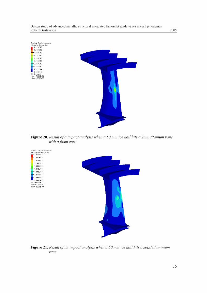
Figure 19. Impact load scenario The result of the analysis is presented in Table 7 while Figure 20 shows the result of an impact analysis when a 50 mm ice hail hits a 2 mm titanium vane with a foam core. Figure 21 shows the result of an impact analysis when a 50 mm ice hail hits a solid aluminium vane.

Design study of advanced metallic structural integrated fan outlet guide vanes in civil jet engines Robert Gustavsson 2005
35
Table 7. Result of the impact analysis t
[mm] εlimit, 25 mm
[%] εultimate, 50 mm
[%] εps/εps_rup
[%] σlimit
[MPa] σultimate [MPa]
Titanium 6-4 1.5 0.299 1.280 1.533 322.92 1382.4 Titanium 6-4 1.8 0.186 0.812 0.972 200.88 876.96 Titanium 6-4 *) 2.0 0.158 0.694 0.831 170.64 749.52 Titanium 6-4 2.0 0.141 0.622 0.745 151.20 671.76 Titanium 6-4 *) 2.5 0.077 0.377 0.452 83.59 407.16 Titanium 6-4 2.5 0.086 0.373 0.447 92.56 402.84 Titanium 6-4 solid 0.061 0.316 0.378 65.84 341.17 Aluminium 2219 2.0 0.204 0.895 1.357 146.88 644.40 Aluminium 2219 3.0 0.084 0.658 0.9974 60.05 473.76 Aluminium 2219 solid 0.061 0.325 0.493 43.70 234.00 *) Vane not filled with PMI-foam εps_rup is the strain rupture of the material and the ratio εps/εps_rup, which can be seen in Table 7, must therefore be under 1 to avoid rupture. Titanium 6-4 Aluminium 2219 εps_rup 0.8348 εps_rup 0.6597 yield strength 880 MPa yield strength 395 MPa ultimate tensile strength 950 MPa ultimate tensile strength 475 MPa E-modulus 108 GPa E-modulus 72 GPa The titanium vane with a sheet thickness of 1.5 mm will cause rupture on the structure since the stress is above the ultimate tensile strength and the configuration with a thickness on 1.8 mm is dangerously close the limit of 880 MPa. The conclusion is that a minimum thickness of a titanium vane with a foam core is 1.8 mm but 2.0 mm is recommendable. Notice also that a vane with a thickness of 2 mm and no foam core will get approximately 80 MPa higher maximum stress compared with a vane with a foam core. The comparison is made between two different vanes with same weight. This shows how the core material in a sandwich structure affects the structural stiffness and strength properties of the vane. The result also shows that a hollow aluminium vane can not stand up to the requirements of an impact load since the stresses will be too high for aluminium with an ultimate tensile strength of 475 MPa. Therefore, only solid aluminium vanes were analysed further since this is the only configuration in aluminium that can fulfil all the demands of the strength requirements.
Design study of advanced metallic structural integrated fan outlet guide vanes in civil jet engines Robert Gustavsson 2005
36
Figure 20. Result of a impact analysis when a 50 mm ice hail hits a 2mm titanium vane
with a foam core
Figure 21. Result of an impact analysis when a 50 mm ice hail hits a solid aluminium vane

Design study of advanced metallic structural integrated fan outlet guide vanes in civil jet engines Robert Gustavsson 2005
37
10.3. WEM-analysis The whole engine model (WEM) and the load cases discussed previously form the basis for the stiffness analysis of the IMC and OGV structure. No hollow vanes in aluminium have been analysed under limit and ultimate load conditions since the impact analysis showed that only solid aluminium vanes fulfil the strength requirements. 10.3.1. Limit load conditions The result from the limit load cases can be seen in Table 8 and shows that the displacements for node 1 and 6 in different configurations during an arbitrary gust, since this became the worst limit load case during the analysis. Node 1 in the centre of the fan and node 6 is the centre of the load bearing in the IMC-structure. The y-and z-directions can bee seen in Figure 23, Figure 24 and Figure 25.
Table 8. Displacements of node 1 and 6 during an arbitrary gust [mm] Node 1 Node 6
Conf. y z y z 1 -2.81 -9.06 -5.19 -10.52 2 -2.32 -8.80 -4.48 -10.17 3 -3.50 -9.55 -6.81 -11.30
Conf: 1. Titanium vanes with a thickness of 2 mm with foam core
2. Solid titanium vanes 3. Solid aluminium vanes
Relative displacement conf.1: 24.206.981.252.1019.5 2222 =+−+ Relative displacement conf.2: 01.280.832.317.1048.4 2222 =+−+ Relative displacement conf.3: 02.355.950.330.1181.6 2222 =+−+ Figure 22 shows the global displacements of the engine from a WEM-analysis with 2 mm titanium vanes with a foam core. Figure 23, Figure 24 and Figure 25 shows the displacements of node 1 and 6 which is presented in Table 8. The stresses obtained from the limit load cases showed that all configurations fulfilled the demands of stiffness- and strength since the yield strength in none of the configurations was exceeded.

Design study of advanced metallic structural integrated fan outlet guide vanes in civil jet engines Robert Gustavsson 2005
38
Figure 22. WEM displacement during a limit load case simulating an arbitrary gust
Figure 23. Displacement of node 1 and 6 during a limit load case simulating an arbitrary
gust with 2 mm titanium vanes with foam core

Design study of advanced metallic structural integrated fan outlet guide vanes in civil jet engines Robert Gustavsson 2005
39
Figure 24. Displacement of node 1 and 6 during a limit load case simulating an arbitrary
gust with solid titanium vanes
Figure 25. Displacement of node 1 and 6 during a limit load case simulating an arbitrary
gust with solid aluminium vanes

Design study of advanced metallic structural integrated fan outlet guide vanes in civil jet engines Robert Gustavsson 2005
40
10.3.2. Ultimate load conditions The worst load case scenario under an ultimate load condition is a rotating imbalance caused by a fan blade out. When a fan blade releases from the fan and hits the containment zone, its kinetic energy will induce a large turning momentum on the fan case. This moment is to be absorbed by the intermediate case and the integrated outlet guide vanes. In the fan blade out analysis this force of 600 kN at the fan centre of gravity, caused by the rotation imbalance, has been the input in this analysis. Figure 26 shows the result of stresses obtained of an FBO analysis of a 2 mm titanium vane with a foam core.
Figure 26. Result showing the stresses obtained during a FBO analysis of a 2mm
titanium vane with a foam core The different values on the legend-scale in the picture correspond to the material properties of titanium and aluminium. The first two is the yield strength (blue) and ultimate tensile strength (green) of aluminium and the next two the yield strength (yellow) and ultimate tensile strength (red) of titanium. This scale on the legend is the same for all of the FBO-plots that are presented in this chapter.
High stress concentrations at top engine mounts and gear box

Design study of advanced metallic structural integrated fan outlet guide vanes in civil jet engines Robert Gustavsson 2005
41
The maximum stresses will not unexpectedly occur on the vanes at the top engine mounts and at the gear box and especially in the connections between the vane and the inner and outer rings. The high stresses at the connections between the vanes and ring are not that high in the reality since only shell elements has been used there. This will lead to unreasonable high stress concentrations at these areas. At these places on the IMC-structure detailed stress analyses must be done to investigate the high stresses more thorough. This means a FE-model with solid elements and radiuses can be introduced at the connections between vane and ring. But since a detailed stress analysis hasn’t been done during this thesis work a more widespread stress criteria must be set up. It is very important to set up correct and equal stress criteria between the configurations so an accurate and reasonable comparison between the different configurations can be made. It was decided that during a fan blade out, not more then 5-8 % of the length of the vane may not bee exposed to stresses over the yield strength of the material. This would correspond to four elements out from the connection between vane and ring since an element length of approximately 10x10 mm was used. Similar criteria was set for the ultimate tensile strength for the material, but only two elements at the connections were allowed to be above limit, which corresponds to approximately 2-4 % of the vane length. Figure 26 shows the stress cause by a FBO of a 2 mm titanium vane with a foam core and it shows that small areas will exceed the yield- and ultimate tensile strength. But these stresses fall in to the stress criteria that were set up since the areas became too small. A more detailed picture over the interesting areas with the highest stresses can be seen in Figure 27 and Figure 28.
Figure 27. Result showing the stresses obtained during a FBO analysis of 2 mm titanium
vanes with a foam core at the top engine mounts

Design study of advanced metallic structural integrated fan outlet guide vanes in civil jet engines Robert Gustavsson 2005
42
Figure 28. Result showing the stresses obtained during a FBO analysis of 2 mm titanium
vanes with a foam core at the gear box A FBO analysis has also been done on solid aluminium vanes and 2 mm titanium vanes with a foam core at the engine mounts and gear box. The result showed that the stresses on the vanes near the top engine mount and gear box will be too high for aluminium, see Figure 29 and Figure 30. Since the areas where the ultimate tensile strength was exceeded were too large, a modification has to be made if this vane configuration is to be used. One thing is to increase the thickness of the aero profile so it will have a bigger cross sectional area, which will decrease the stresses in the structure. But this will increase the weight of the vane which is an unwanted effect. One interesting result was that 2 mm titanium vanes with a foam core at the top engines mounts and gear box combined with solid aluminium vanes “on the sides” caused higher stresses on the aluminium vanes compared to if only solid aluminium vanes are used. The stress level of the aluminium vanes became so high that it would be difficult to realize this configuration. The explanations for this is that this configurations with both titanium and aluminium vanes will have different stiffness/strength properties around the IMC and therefore cause higher stresses on the aluminium vane, which has a lower specific strength compared to titanium. If a configuration with different strength and stiffness properties around the configuration is used it will deform asymmetrically, even under a symmetric load, creating high-stress areas where the aluminium vanes are located. Therefore it is better to only have aluminium vanes compared to have titanium vanes at the top engine mounts and gear box and solid aluminium vanes “on the sides”.

Design study of advanced metallic structural integrated fan outlet guide vanes in civil jet engines Robert Gustavsson 2005
43
Figure 29. Result showing the stresses obtained during a FBO analysis of solid
aluminium vanes and 2 mm titanium vanes with a foam core at the engine mounts and gear box. Picture shows the vanes at the top engine mounts
Figure 30. Result showing the stresses obtained during a FBO analysis of solid
aluminium vanes and 2 mm titanium vanes with a foam core at the engine mounts and gear box. This picture shows the vanes at the gear box

Design study of advanced metallic structural integrated fan outlet guide vanes in civil jet engines Robert Gustavsson 2005
44
10.4. Buckling When the intermediate case is subjected to large compressive forces, there is a risk for buckling phenomena. Euler-buckling theory is used to determine the stresses caused by the applied load and restraints on the structure, and the analysis result is a buckling load factor that is applied as a multiplier to the applied load. The load application can be seen in Figure 31. Certain areas of the IMC are estimated to be more sensitive regarding to buckling. This sensitivity is especially true for the outlet guide vanes. Evaluating the sheet thickness a linear buckling analysis was made to locate these sensitive areas of the IMC and the OGV. The buckling analysis has been carried out on a sector shown in Figure 17.
Figure 31. FE-model of the buckling analysis.
The applied force is shown in the picture The applied force was 100 kN. This force is estimated to rise during a FBO. The buckling requirement for this kind of model is 3. Therefore a buckling load factor of 3 must be obtained during the buckling analysis with buckling force of 100 kN. The analysis shows that almost every configuration fulfils the buckling requirements, see Table 9. The most interesting result with this analysis is that a 2 mm titanium vane without a foam core will not fulfil the buckling requirement of a buckling factor of 3 compared to a 2 mm titanium vane with a foam core. This shows that the foam contributes the structure with extra resistance to buckling. To fulfil the buckling requirements with a titanium vane without a foam core the sheet thickness must be around 2.5 mm with in the end will lead to a heavier configuration compared the a 2 mm titanium vane with a foam core. Figure 32 shows the result of a buckling analysis of a 2 mm titanium vane with a foam core.

Design study of advanced metallic structural integrated fan outlet guide vanes in civil jet engines Robert Gustavsson 2005
45
Table 9. Buckling load factor and buckling load Thickness
[mm] Buckling load
factor Buckling load
[kN] Titanium 6-4 1.5 2.7 270 Titanium 6-4 1.8 3.7 370 Titanium 6-4*) 2.0 2.2 220 Titanium 6-4 2.0 4.3 430 Titanium 6-4*) 2.5 3.8 380 Titanium 6-4 2.5 6.0 600 Titanium 6-4 3.0 7.9 790 Titanium 6-4 solid 9.8 980 Aluminium 2219 2.0 3.7 370 Aluminium 2219 3.0 6.6 660 Aluminium 2219 solid 8.7 870 *) Vane not filled with PMI-foam
Figure 32. The first buckling mode for a titanium vane with a thickness of 2 mm
and foam core
Design study of advanced metallic structural integrated fan outlet guide vanes in civil jet engines Robert Gustavsson 2005
46
11. Conclusion
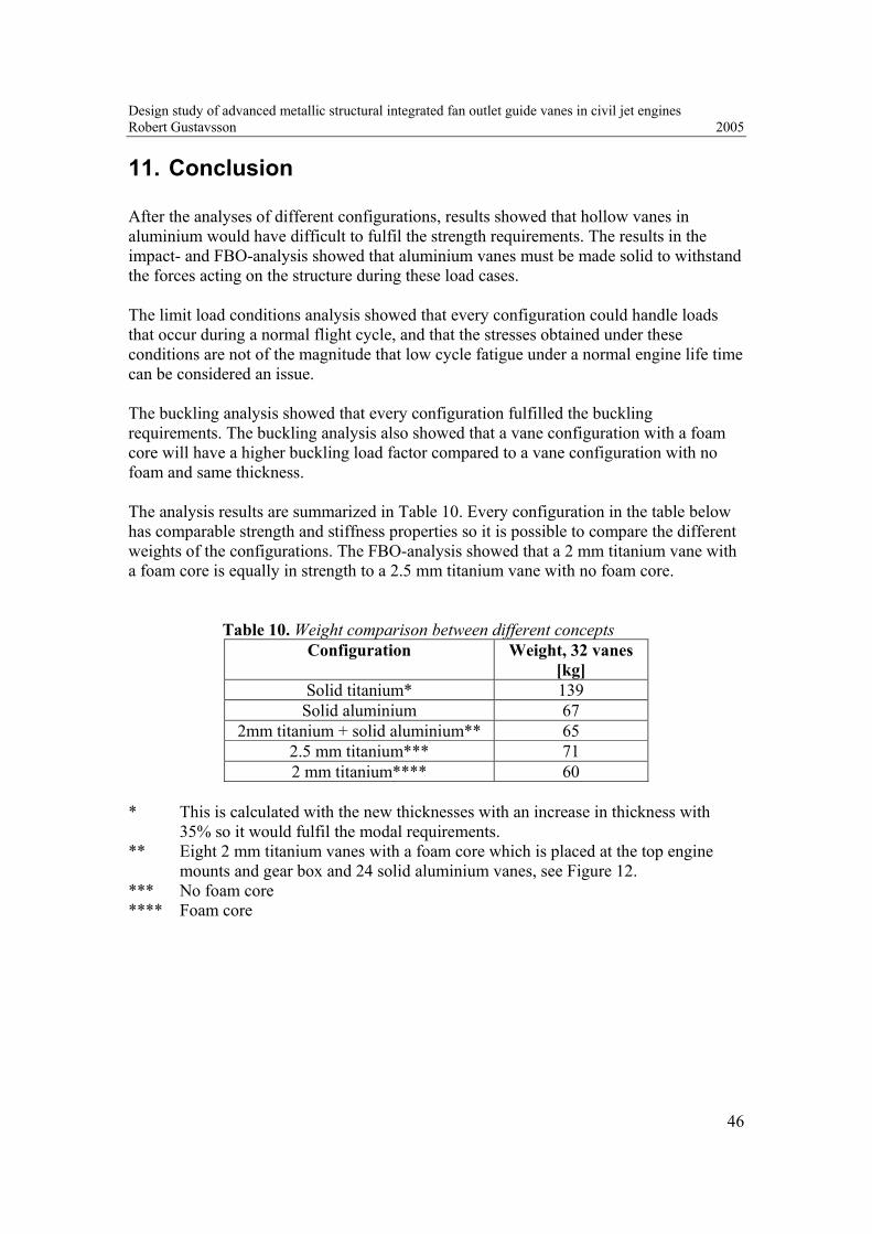
After the analyses of different configurations, results showed that hollow vanes in aluminium would have difficult to fulfil the strength requirements. The results in the impact- and FBO-analysis showed that aluminium vanes must be made solid to withstand the forces acting on the structure during these load cases. The limit load conditions analysis showed that every configuration could handle loads that occur during a normal flight cycle, and that the stresses obtained under these conditions are not of the magnitude that low cycle fatigue under a normal engine life time can be considered an issue. The buckling analysis showed that every configuration fulfilled the buckling requirements. The buckling analysis also showed that a vane configuration with a foam core will have a higher buckling load factor compared to a vane configuration with no foam and same thickness. The analysis results are summarized in Table 10. Every configuration in the table below has comparable strength and stiffness properties so it is possible to compare the different weights of the configurations. The FBO-analysis showed that a 2 mm titanium vane with a foam core is equally in strength to a 2.5 mm titanium vane with no foam core.
Table 10. Weight comparison between different concepts Configuration Weight, 32 vanes
[kg] Solid titanium* 139
Solid aluminium 67 2mm titanium + solid aluminium** 65
2.5 mm titanium*** 71 2 mm titanium**** 60
* This is calculated with the new thicknesses with an increase in thickness with
35% so it would fulfil the modal requirements. ** Eight 2 mm titanium vanes with a foam core which is placed at the top engine
mounts and gear box and 24 solid aluminium vanes, see Figure 12. *** No foam core **** Foam core

Design study of advanced metallic structural integrated fan outlet guide vanes in civil jet engines Robert Gustavsson 2005
47
There is also of interest to see what kind of mechanical demand that will be the dimensioning analysis for each of the configurations with different materials. This is presented in Table 11 below. Table 11. Critical requirements analysis for each configuration
Vane configuration Modal Impact Strength Solid aluminium X Solid titanium X 2mm aluminium with foam a foam core X - 2mm aluminium X - 2mm titanium with a foam core X 2mm titanium X
The solid titan configuration does not fulfil the eigenfrequency demands with the first local eigenmode over 325 Hz. To fulfil the modal requirements a more ticker vane-profile of approximately 35% is needed and this leads to an increase in weight by 1.13 kg. Solid aluminium is on the limit to fulfil 325 Hz. But aluminium has a low specific strength and that leads to that it will be an FBO that will be the dimensioning analysis. But solid aluminium vanes have a higher mass then a hollow titanium vane which is a big disadvantage. Hollow titanium vanes have extraordinary strength to weight properties which means that a smaller thickness is possible compared to aluminium and that leads to weight reduction. If the vane has a foam core the eigenmodes will be high above limit compared to a vane with no foam core so only the strength analysis was the dimensioning one. The FBO analysis together with the impact analysis resulted in that a sheet thickness of 2 mm became the best configuration. This together with a core consisting of polymer foam will increase the local eigenmodes, approximately 5%, which is a good advantage when dealing with thin and long structures like integrated outlet guide vanes.

Design study of advanced metallic structural integrated fan outlet guide vanes in civil jet engines Robert Gustavsson 2005
48
12. Discussion
The cost aspect is something that has not been considered in this work, and there is something to think about in the cost aspect when designing integrated outlet guide vanes, One thing to consider is that; what is the most desirable, a vane with high material and manufacturing cost with a low weight like a hollow titanium vane or a solid aluminium vane with a less expensive material and manufacturing cost with a higher weight? The answer to that is probably a more expensive OGV with a low weight since low weight is something that every engine manufacturers struggle to accomplish and therefore probably willing to pay some extra for. By making the outlet guide vanes hollow the weight will decrease. But making them hollow will lead to a more complicated manufacturing. If the vanes have been solid, casting could have been an option. But making the vanes hollow it will be very difficult to cast these profiles so a fabrication technique must be developed, which may lead to a higher manufacturing cost. Also the choice of titanium before aluminium will lead to higher material cost. It is also more difficult to machine titanium than aluminium which leads to a higher manufacturing cost.

Design study of advanced metallic structural integrated fan outlet guide vanes in civil jet engines Robert Gustavsson 2005
49
13. Future work
The analysis made during this thesis work has only been a comparison between hollow vanes with solid vanes. During the analysis it became obvious that the highest stresses on the structure will be at the connections between the vane and the fan hub frame and the outer ring. Therefore a more detailed stress analysis with solid elements must be done to get a closer look at the connections and also to decide the radiuses between the vane and connecting parts. The manufacturing aspect must be considered. Since one-piece casting is not a good option many different ways of making these outlet guide vanes are available. One way is presented in this report, but their might be better solutions to manufacture these vanes since a thorough investigation not has been done in this area. Also a cost comparison between the different configurations must be done. The cost aspect is an important thing to consider when choosing concepts. Price comparison between the different materials, aluminium and titanium, must be done and also a more detailed manufacturing preparation with the different manufacturing techniques and costs for each of the materials must be worked out properly before any final concept is chosen.
Design study of advanced metallic structural integrated fan outlet guide vanes in civil jet engines Robert Gustavsson 2005
50
14. References
Literature Sirius (2002-2003), Intermediate case for the jet engine RM250-2s Universitetstryckeriet, Luleå University of Technology Granberg P., Hiswåls F. (2002). Intermediate case with integrated outlet guide vanes – A concept study of the mechanical behavior of integrated outlet guide vanes in aluminium Master thesis, Luleå University of Technology Westman E-L. (2003), Litteraturstudie; Formning i Titan Division of solid mechanics, Luleå University of Technology U.S. Department of Transportation, Federal Aviation Administration, Office of Aviation Research (2003). Metallic Materials Properties Development and Standardization (MMPDS) Washington D.C. 20591 Internet 2005-12-08 Degussa, www.performance-plastics.com 2005-12-08 The Aluminium Association, Inc., www.aluminum.org 2005-12-08 Key to metals, www.key-to-metals.com 2005-12-08 RTI International metalls, Inc., www.rti-intl.com/

Design study of advanced metallic structural integrated fan outlet guide vanes in civil jet engines Robert Gustavsson 2005
APPENDIX
Title Number of pages 1. The target engine data 1 2. Material properties of ROHACELL® A 1
3. Material properties of ROHACELL® WF 1
4. Poisson ratio of ROHACELL® 1
5. Element thicknesses 1
6. List of computer files available at VAC 3

Thesis work: Integrated outlet guide vanes Robert Gustavsson Volvo Aero Corporation 2005
1
Appendix 1. The target engine data A specific target engine design is chosen to allow detailed requirements to be defined for the integrated guide vanes. The target engine design is a 2-spool installation, in the thrust range 133kN (30 lbf). A 2-spool engine means that the engine and the LPT must be driven with the same shaft as the fan, which is to slow to be effective. In order to make two spooled engines more effective a geared fan can be introduced. The fan is then rotating separately from the LPT and there by letting the LPT and LPC rotate at higher speeds. Table 12 describes the general characteristics for the target engine. Table 12. General engine characteristics
Characteristic Value Unit
Max Take Off Thrust 133 (30) kN (klb)
Engine Weight (target) < 2500 kg
By-Pass Ratio ~10-12 1
Fan Tip Diameter 1.7 (67) m (in)
Engine Length ~2.9 (114) m (in)
Description
Engine Installation Under wing
Forward Mount Hybrid Mount: Engine mount on outer bypass duct, core mounted thrust lugs
Gearbox Nacelle mounting (Core mount optional) The bypass ratio in a jet engine is the ratio between how much air that passes outside the core in the by-pass channel and the amount of air that passes through the core and in to the combustion process. About 75-80 percent of the total thrust of the engine is generated by the by pass air and it contributes to a large extent to the ability of noise reduction and fuel economy.

Thesis work: Integrated outlet guide vanes Robert Gustavsson Volvo Aero Corporation 2005
2
Appendix 2. Material properties of ROHACELL® A ROHACELL® A: Aircraft
ROHACELL® A (Aircraft grade) is a closed-cell rigid foam plastic based on PMI (polymethacrylimide) which does not contain any CFCs. The field of application for ROHACELL® A is aircraft construction. Curing temperature up to 130C (266F). Curing pressure up to 0.35 MPa (50 psi). Sandwich components using ROHACELL® A as core material can be realized in a single work step (= cocuring). The structural components can be manufactured in an autoclave and by means of RTM. ROHACELL® A is easy to shape. Thermoformability is another advantage of the core material.
Technical Data Heat distortion temperature 180°C, densities from 30 to 75 kg/m³, compressive strength 0.4 to 1.5 MPa, processing up to 125°C/0.35 MPa
Physical Forms Sheets and blocks in thicknesses of 4 to 85 mm (other thicknesses on request), sizes up to 2.500 x 1.250 mm
Properties Unit ROHACELL® 31 A
ROHACELL® 51 A
ROHACELL® 71 A
ROHACELL® 110 A
Standard
Density kg/m3 lbs./cu.ft.
32 2.0
52 3.25
75 4.68
110 6.87
DIN 53420/ISO 845 ASTM D 1622
Compressive strength
MPa psi
0.4 58
0.9 130
1.5 217
3.0 435
DIN 53421/ISO 844 ASTM D 1621
Tensile strength MPa psi
1.0 145
1.9 275
2.8 406
3.5 507
DIN 53455/ISO 527-2 ASTM D 638
Flexural strength MPa psi
0.8 116
1.6 232
2.5 362
4.5 652
DIN 53423/ISO 1209 ASTM D 790
Shear strength MPa psi
0.4 58
0.8 116
1.3 188
2.4 348
DIN 53294 ASTM C 273
Elastic modulus MPa psi
36 5,220
70 10,150
92 13,340
160 23,200
ISO 527-2 ASTM D 638
Shear modulus MPa psi
13 1,885
19 2,775
29 4,205
50 7,250
DIN 53294 ASTM C 273
Elongation at break
% 3.5 4.0 4.5 4.5 DIN 53455/ISO 527-2 ASTM D 638
Heat distortion resistance
°C °F
180 356
180 356
180 356
180 356
DIN 53424

Thesis work: Integrated outlet guide vanes Robert Gustavsson Volvo Aero Corporation 2005
3
Appendix 3. Material properties of ROHACELL® WF ROHACELL® WF: Aerospace, higher heat distortion resistance
ROHACELL® WF (= grade with increased heat distortion resistance) is a closed-cell rigid foam plastic based on PMI (polymethacrylimide) which does not contain any CFCs. ROHACELL® WF serves as a core material in advanced sandwich components used in aircraft and spacecraft construction. Curing temperature up to 180C (356F). Curing pressure up to 0.70 MPa (100 psi). Sandwich components using ROHACELL® WF as core material can be realized in a single work step (= cocuring). The structural components can be manufactured in an autoclave and by means of RTM. ROHACELL® WF is easy to shape. Thermoformability is another advantage of the core material.
Technical Data Heat distortion temperature 205°C, densities from 52 to 200 kg/m³, compressive strength 0.8 to 15.8 MPa, processing up to 180°C/0.7 MPa
Physical Forms Sheets and blocks in thicknesses of 4 to 70 mm (other thicknesses on request), sizes up to 2.500 x 1.250 mm
Properties Unit ROHACELL® 51 WF
ROHACELL® 71 WF
ROHACELL® 110 WF
ROHACELL® 200 WF
Standard
Density kg/m3 lbs./cu.ft.
52 3.25
75 4.68
110 6.87
205 12.81
DIN 53420/ISO 845 ASTM D 1622
Compressive strength
MPa psi
0.8 116
1.7 246
3.6 522
9.0 1,305
DIN 53421/ISO 844 ASTM D 1621
Tensile strength MPa psi
1.6 232
2.2 319
3.7 536
6.8 986
DIN 53455/ISO 527-2 ASTM D 638
Flexural strength MPa psi
1.6 232
2.9 420
5.2 754
12.0 1,740
DIN 53423/ISO 1209 ASTM D 790
Shear strength MPa psi
0.8 116
1.3 188
2.4 348
5.0 725
DIN 53294ASTM C 273
Elastic modulus MPa psi
75 10,875
105 15,225
180 26,100
350 50,750
ISO 527-2ASTM D 638
Shear modulus MPa psi
24 3,480
42 6,090
70 10,170
150 21.750
DIN 53294ASTM C 273
Elongation at break
% 3,0 3.0 3.0 3.5 DIN 53455/ISO 527-2 ASTM D 638
Heat distortion resistance
°C °F
205 401
200 392
200 392
200 392
DIN 53424

Thesis work: Integrated outlet guide vanes Robert Gustavsson Volvo Aero Corporation 2005
4
Appendix 4. Poisson ratio of ROHACELL® The values were determined in a tensile test according DIN 53455/ASTM D 1622. Due to the measuring method with the strain gauges there is a scattering of the values. The values represent a series of measurements carried out of Röhm in 1992.
Table 13. Poisson ratio
RC Type Poisson ratio
RC 31 IG / A 0.43 RC 51 IG / A 0.40 RC 71 IG / A 0.37
RC 110 IG / A 0.38 RC 51 WF 0.34 RC 71 WF 0.37 RC 110 WF 0.37 RC 200 WF 0.33 RC 300 WF 0.38

Thesis work: Integrated outlet guide vanes Robert Gustavsson Volvo Aero Corporation 2005
5
APPENDIX 5. Element thicknesses The different element thicknesses used in the FE-model of the solid vane can be seen in Table 14. Each lay-up symbolizes the different element properties which can bee seen in Figure 33.
Table 14. Element thickness
Figure 33. Different lay-ups of the vane
Lay up
Element thickness [mm]
1 4.25 2 5.75 3 7.75 4 10.25 5 10.75 6 11.25 7 10.75 8 10.25 9 8.75
10 7.75 11 6.75 12 4.75 13 3.25 14 2.25

Thesis work: Integrated outlet guide vanes Robert Gustavsson Volvo Aero Corporation 2005
6
Appendix 6. List of computer files available at VAC Thesis report F:\Verksamh\Teknologi\ExjobbVT2005\Robert G\Projektdokument\Rapport\… Modal analysis F:\Verksamh\Teknologi\ExjobbVT2005\Robert G\Analys\Modal\… Modal_foamcore.hm Modal_hollow.hm Modal_solid_PSHELL.hm Modal_foamcore.res Modal_hollow.res Modal_solid_PSHELL.res Buckling analysis F:\Verksamh\Teknologi\ExjobbVT2005\Robert G\Analys\Buckling\… Buckling_solid_PSHELL.hm Titan\Buckling_2mmTi_foamcore.dat Titan\Buckling_2mmTi_hollow.dat Titan\Buckling_3mmTi_foamcore.dat Titan\Buckling_15mmTi_foamcore.dat Titan\Buckling_18mmTi_foamcore.dat Titan\Buckling_25mmTi_foamcore.dat Titan\Buckling_25mmTi_hollow.dat Titan\Buckling_solidaTi_PSHELL.dat Aluminium\Buckling_2mmAl_foamcore.dat Aluminium\Buckling_3mmA_foamcore.dat Aluminium\Buckling_solidaAl_PSHELL.dat

Thesis work: Integrated outlet guide vanes Robert Gustavsson Volvo Aero Corporation 2005
7
Impact analysis F:\Verksamh\Teknologi\ExjobbVT2005\Robert G\Analys\Impact\… Impact.hm Impact_solid_PSHELL.hm Impact_forces\Force_Al_25mm_tid10.bdf Impact_forces\Force_Al_50mm_tid10.bdf Impact_forces\Force_Ti_25mm_tid10.bdf Impact_forces\Force_Ti_50mm_tid10.bdf Titan\Impact_18mmTi_foamcore.bdf Titan\Impact_18mmTi_foamcore_25mm.dat Titan\Impact_18mmTi_foamcore_50mm.dat Titan\Impact_2mmTi_foamcore.bdf Titan\Impact_2mmTi_foamcore_25mm.dat Titan\Impact_2mmTi_foamcore_50mm.dat Titan\Impact_2mmTi_hollow.bdf Titan\Impact_2mmTi_hollow_25mm.dat Titan\Impact_2mmTi_hollow_50mm.dat Titan\Impact_25mmTi_hollow.bdf Titan\Impact_25mmTi_hollow_50mm.dat Titan\Impact_solidTi_PSHELL.bdf Titan\Impact_solidTi_PSHELL_25mm.dat Titan\Impact_solidTi_PSHELL_50mm.dat Aluminium\Impact_2mmAl_foamcore.bdf Aluminium\Impact_2mmAl_foamcore_25mm.dat Aluminium\Impact_2mmAl_foamcore_50mm.dat Aluminium\Impact_3mmAl_foamcore.bdf Aluminium\Impact_3mmAl_foamcore_25mm.dat Aluminium\Impact_3mmAl_foamcore_50mm.dat Aluminium\Impact_solidAl_PSHELL.bdf Aluminium\Impact_solidAl_PSHELL_25mm.dat Aluminium\Impact_solidAl_PSHELL_50mm.dat
Thesis work: Integrated outlet guide vanes Robert Gustavsson Volvo Aero Corporation 2005
8
WEM analysis F:\Verksamh\Teknologi\ExjobbVT2005\Robert G\Analys\WEM\… Helmotormodell.hm Helmotormodell_foamcore_pylon.hm Helmotormodell_foamcore_solid_PSHELL_pylon.hm Helmotormodell_hollow_pylon.hm Helmotormodell_solid_PSHELL_pylon.hm Limit_load_cases\Helmotormodell_limit_2mmTi_foamcore.dat Limit_load_cases\Helmotormodell_limit_2mmTi_foamcore.bdf Limit_load_cases\Helmotormodell_limit_2mmTi_hollow.dat Limit_load_cases\Helmotormodell_limit_2mmTi_hollow.bdf Limit_load_cases\Helmotormodell_limit_25mmTi_foamcore.dat Limit_load_cases\Helmotormodell_limit_25mmTi_foamcore.bdf Limit_load_cases\Helmotormodell_limit_25mmTi_hollow.dat Limit_load_cases\Helmotormodell_limit_25mmTi_hollow.bdf Limit_load_cases\Helmotormodell_limit_solidAl_PSHELL.dat Limit_load_cases\Helmotormodell_limit_solidAl_PSHELL.bdf Limit_load_cases\Helmotormodell_limit_solidTi_PSHELL.dat Limit_load_cases\Helmotormodell_limit_solidTi_PSHELL.bdf Limit_load_cases\TOrot\Helmotormodell_limit_TOrot_2mmTi_foamcore.dat Limit_load_cases\TOrot\Helmotormodell_limit_TOrot_2mmTi_foamcore.bdf Imbalance\Helmotormodell_imbalance_2mmTi_foamcore.dat Imbalance\Helmotormodell_imbalance_2mmTi_foamcore.bdf Imbalance\Helmotormodell_imbalance_2mmTi_hollow.dat Imbalance\Helmotormodell_imbalance_2mmTi_hollow.bdf Imbalance\Helmotormodell_imbalance_18mmTi_foamcore.dat Imbalance\Helmotormodell_imbalance_18mmTi_foamcore.bdf Imbalance\Helmotormodell_imbalance_25mmTi_foamcore.dat Imbalance\Helmotormodell_imbalance_25mmTi_foamcore.bdf Imbalance\Helmotormodell_imbalance_25mmTi_hollow.dat Imbalance\Helmotormodell_imbalance_25mmTi_hollow.bdf Imbalance\Helmotormodell_imbalance_2mmTi_foamcore_solidAl_PSHELL.dat Imbalance\Helmotormodell_imbalance_2mmTi_foamcore_solidAl_PSHELL.bdf Imbalance\Helmotormodell_imbalance_solidAl_PSHELL.dat Imbalance\Helmotormodell_imbalance_solidAl_PSHELL.bdf Imbalance\Helmotormodell_imbalance_solidTi_PSHELL.dat Imbalance\Helmotormodell_imbalance_solidTi_PSHELL.bdf


![2. AXIAL FLOW FANS€¦ · Fan with profile blades of adjustable stagger angle. No guide vanes [6] Dr. János VAD – AXIAL FLOW TURBOMACHINERY 3 Fig. 2.7. Industrial fan. Outlet](https://img.pdfslide.us/doc/110x75/5f0588f07e708231d4137189/2-axial-flow-fans-fan-with-profile-blades-of-adjustable-stagger-angle-no-guide.jpg)