Embed Size (px)
Citation preview
Design Standards No. 3
CANALS AND RELATED STRUCTURES
CHAPTER 1 CANAL AND LATERALS
2 GENERAL DESIGN INFORMATION FOR STRUCTURES
3 DIVERSION DAMS
4 DIVERSION HEADWORKS 5 CANAL STRUCTURES 6 WATER MEASUREMENT STRUCTURES 7 CROSS DRAINAGE AND PROTECTIVE STRUCTURES 8 PIPE DISTRIBUTION SYSTEMS
9 BRIDGES
UNITED STATES DEPARTMENT OF THE INTERIOR
BUREAU OF RECLAMATION
OFFICE OF CHIEF ENGINEER DENVER, COLORADO
IINITED STATES DEPAR’I’MENT OF THE INTERIOR
EUREAU C F H ECLOAMA TION Office of Cl-,icf Engineer -. ‘.-.. ‘-“WI’, Colorado 80225
TRANSMITTAL OF DESIGN STANDARDS
Number and Title:
Release No. DS-3-5
Design Standards No. 3 - CANALS AND RELATED STRUCTURES
Insert Sheets:
Design Standards No. 3 (182 sheets)
Remove Sheets:
Design Standards No. 3
Other revisions:
Summary of changes:
This Design Standards has been completely revised and updated to present current Bureau ‘- practice in the design of canals and related structures. Among the more significant changes or
additions are the following:
1. A statement of the Bureau’s new waterway policy, which places emphasis on lining waterways or placing them in pipes.
2. A description of several types of autcmatic control features, and a discussion of the importance of considering automation of a canal system in the planning and design stage.
3. An increase in the maximum concrete compressive stress from 3,000 to 3,750 pounds per square inch.
NOTE: This is a complete replacement for Design Standards No. 3.
Approved:
Acting Chief Engine December 8, 1367
Date
n (To be filled in by employee who files this release in appropriate folder.
The above change has been made in the Design Standards.
Signature mte
UNITED STATES DEPARTMENT OF THE INTERJOR
BUREAU OF RECLAMATION
DESIGN STANDARDS NC. 3
CANALS AND RELATED STRUCTURES .
TABLE OF CONTENTS
Chapter 1 Canals and Laterals 2 General Design Information for Structures 3 Diversion Dams 4 Diversion Headworks 5 Canal Structures 6 Water Measurement Structures 7 Cross Drainage and Protective Structures 8 Pipe Distribution Systems 9 Bridges
DS-3-5 - 12/8/67 . . . Ill
Canals and Related Structures Chap. 1 Canals and Laterals
TcELE OF CONTENTS
GENERAL REQUIREMENTS
.
.
Paraqraph
1.1 Introduction 1. 2 Water Demand 1.2A Acreage to be Irrigated 1.2B Duty of Water 1.2c Seepage Losses 1.2D Evaporation 1.3 Flow Capacity
:::
::t
:-i 1: 10 1.11 1.12 1.13
1. i4 1.15 1.15A 1.15B 1.15c i. 16 1.17 1.18 1.19 1.20 1.2OA 1.20B i. 20C 1.21 1.22
1.23 Power Canals 1.23A Hydraulic Bore 1.24 Drainage Systems 1.25 Wasteway Channels
CANAL LINING POLICY
PoIicy Justification
UNLINED CANALS OR LATERALS
Definition Cross Section Location Curvature and Velocity Freeboard Bank Top Width an? Berm Flow Formulas Hydraulic Bore
LINED CANALS OR LATERALS
Definition Cross Section
Hard-surface Linings Buried-membrane Linings Earth Linings
Location Curvature and Velocity Freeboard Bank Top Width and Berm Flow Formulas
Manning’s Roughness Coefficient Effects of Roughness and Hydraulic Radius Effect of Channel Sinuosity
Hydraulic Bore Winter Operation
OTHER WATERWAYS
DS-3-5 - 12/8/67
Chap. 1 Canals and Laterals Canals and Related Structures
TABLE OF CONTENTS--Continued
Figure Number
, I
2
3A
3B
4
5
6
7
98 10
::: 13
14
DS-3-5 - 2/8/67
LIST OF FIGURES
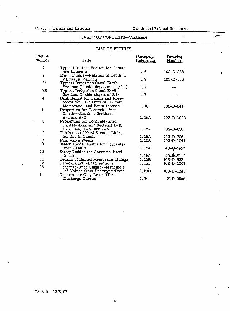
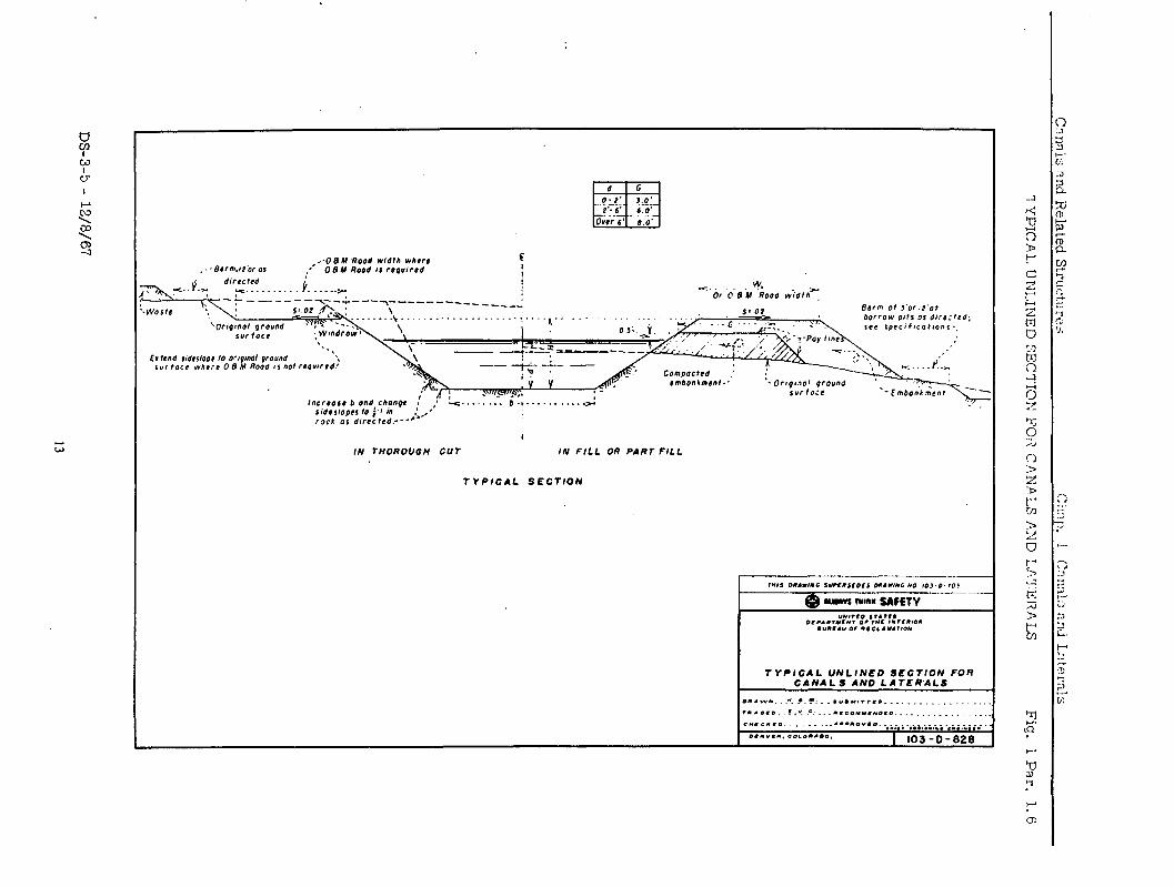
Typical Unlined Section for Canals and Laterals
Earth Canals--Relation of Depth to Allowable Velocity
Typical Irrigation Canal Earth Sections (Inside slopes of l-1/2:1)
Typical Irrigation Canal Earth Sections (Inside slopes of 2~1)
Bank Height for Canals and Free- board for Hard Surface, Buried Membrane, and Earth Linings
Properties for Concrete-lined Canals- -Standard Sections A-l and A-2
Properties for Concrete-lined Canals--Standard Sections B-2, B-3, B-4, B-5, and B-6
Thickness of Hard Surface Lining for Use in Canals
Flap Valve Weeps Safety Ladder Rungs for Concrete-
lined Canals y&ladder for Concrete-lined
. Details of Buried Membrane Linings Typical Earth-lined Sections Concrete-lined Canals--Manning’s
“n” Values from Prototype Tests Concrete or Clay Drain Tile--
Discharge Curves
Paragraph Reference
1.6
1.7
1.7
1.7
g%-$k!f 103-D-828
103-D-308
.--
-- s
1.10 103-D-341
1.15A 103-D-1042
1.15A 103-D-630
1.15A 103-D-706 1.15A 103-D-1044
1.15A
1.15A 1.15B 1.15C
1.2oB
40-p-5927
40-Ib-6112 103-D-632 103-D-1043
103-D-1045
1.24 X-D-3548
.
.
l 4
vi
Canals and Related Structures Chap. 1 Canals and Laterals
.1
.2
GENERAL REQUIREMENTS
The following paragraphs deal briefly with total water demand and flow capacity requirements, the two general requirements which must be ful- filled by any type of canal and lateral system. Except where otherwise noted, the material included herein relates to canals and laterals to be used for irrigation. In the structural designs selected for illustration, there may be instances in which current design practices differ in some respects from those illustrated.
The total water demand requirement to fulfill the project purpose must be provided by the irrigation canal system. It is primarily based upon four factors: acreage to be irrigated, estimated duty of water, estimated seepage losses plus an allowance for operational waste, and evaporation loss.
A.
B.
C.
The net acreage to be irrigated is based on detailed land classification and preliminary canal location surveys. The exact acreage cannot be
Acreage to be
computed until final canal locations are made. Irrigated
The duty of water, or the quantity of water required per acre,’ to be used for preliminary studies of a canal system, may best be estimated from records of the use of water under similar conditions on similar areas and crops. A detailed study of the soil and subsoil character- istics, irrigable land, drainage conditions, methods of water applica- tion, nature of crops, rainfall and evaporation, and other pertinent factors may be required. (See also Part 2 of Volume V, Irrigated Land Use, of the Reclamation Manual, regarding land classification. )
Seepage loss is usually expressed in cubic feet per square foot of wetted area in 24 hours. It is generally estimated from the loss in water depth in a reach of canal having uniform slope and cross section. For preliminary estimates it may be assumed that, in typical unlined earth canals under usual conditions, about one-third of the total water diverted will be lost by seepage, operational waste, and evaporation. Reported seepage losses frequently include a certain amount of struc- ture leakage, operational waste, and overdelivery to the irrigators. Seepage may at times constitute a gain to the canal rather than a loss, if the ground water is sufficiently high and other natural factors are advantageous. (Seepage of irrigation water from higher lands is some- times a contributing factor to high ground water along a canal. ) Thus, an accurate prediction of seepage loss is extremely difficult to make and the results are at best uncertain. The prediction of seepage must therefore be based on judgment within the limits of existing data and natural factors. The Moritz formula sug ests computations of total seepage loss in cubic feet per second (cfs per mile of canal as follows: 7
where
S = loss in cfs per mile of canal, Q = discharge of canal in cfs, V = mean velocity of flow in fps, and C = cubic feet of water lost in 24 hours
through each square foot of wetted area of canal prism.
Observations on eight different projects gave the following average figures for the value of C in earth canals. These factors are suitable
1. 1
INTRODUCTION
WATER DEMAND
Duty of
Water
Seepage Losses
DS-3-5 - 12/8/67
1.m
Evaporation
FLOW CAPACITY
POLICY
Chap. 1 Canals and Laterals Canals and Related Structures
GENERAL REQUIREMENTS--Continued
for rough preliminary estimates, but measurements have shown that actual seepage losses vary widely within each of the general soil types, For design purposes, therefore, it is usually necessary to make estimates of seepage losses in questionable areas on the basis of field tests.
Tvoe of material Value of C
Cemented gravel and hardpan with sandy loam
0.34
Clay and clayey loam Sandy loam Volcanic ash Volcanic’ash with sand Sand and volcanic ash or clay Sandy soil with rock Sandy and gravelly.soil
0.41
EE 0: 98 1.20 1.68 2.20
Seepage losses from properly constructed concrete-lined canals should norm&y be relatively small. However, subsequent partial f-ailure or poor construction or maintenance of the concrete lining may result in large losses. Other types of lining are susceptible to varying amounts of seepage loss, .dependi.ng on the type, quality of construction, and related natural factors. The possibility of appreciable losses from lined canals should be kept in mind when preparing initial estimates of water requirements. Technical Bulletin No. 1203 entitled “Measuring Seepage From Irrigation Channels, ” issue< in September 1959 by the Agriculture Research Service, U. S. Department of Agriculture, will prove helpful in estimating seepage losses.
D. Evaporation from canals and laterals is usually such a small quantity compared with seepage that it may be neglected. However, where there are reservoirs along a canal, evaporation should be considered.
.3 Flow-capacity requirements of various parts of a system are determined and used as a basis of conveyance design. These flow capacities must satisfy the water demand at the various points in the system. The maximum demand may generally be estimated at 125 to 150 percent of the average demand. Systems operating for a 12-month season may require a capacity large enough to carry, in the maximum month, from 10 to 15 percent of the total annual demand. Those operating for a 7-month season may require a capacity large enough to carry, in the maximum month, from 20 to 25 percent or more of the total annual demand. However, capacities should be made adequate to serve the maximum lo-day demand. The actual maximum demand should be determined by detailed analyses of individual projects.
.4
CANAL LINING POLICY
It is the policy of the Bureau of Reclamation, in order to conserve water and to secure other benefits, to consider fully the lining or placing in pipe of all constructed waterways for the conveyance and distribution of project water supplies. In those instances where the recommendations do not call for lining or pipe, full justification for using an unlined waterway will be required. On unauthorized projects for which field studies are not complete, this policy shall be adopted at once. On presently authorized but unconstructed projects, and for those projects on which field investigations are completed, this policy shall be adopted in advance planning studies.
P
c
DS-3-5 - 12/a/67
Canals and Related Structures Chap. 1 Canals and Laterals
1. 5
CANAL LINING POLICY--Continued
. 5 Justification for using unlined waterwaS ‘s is sometimes very complicated because of the large number of factors to be considered.
JUSTIFICATION Consideration
must be given to seepage rates with and without lining, the value of water saved, operation and maintenance costs, drainage costs or value of land taken out of cultivation by seepage, canal size, reservoir size, right-of-way, allowabie velocities, structure costs, and the various types of lining or pipe correlated with the other conditions. Considerations should also include in- tangible factors inherent in a given project to be benefited and values assigned these factors whenever possible; The Bureau’s publication “Economic Justi- fication for Canal Lining in Irrigation Distribution Systems” presents proce- dures and guidelines which can be used in making economic studies.
UNLINED CANALS OR LATERALS
-6 An unlined canal or lateral is defined as an open channel excavated and shaped DEFINITION to the required cross section in natural earth or fill without special treatment of the wetted surface. Compaction of bank or fill material for the purpose of stabilization is not considered as a lining operation. See Figure 1.
.7 The cross section selected for a canal or lateral should be such as to carry the maximum capacity discussed in Paragraph 1.3 and should satisfy the proper relationships between bottom width, water depth, side slopes, free- board, bank dimensions, and future operation and maintenance. The ratio of bottom width to depth usually ranges from 2: 1 for small channels to 8: 1 for canals with capacities of about 10,000 cfs. The side slopes of a canal depend upon the stability of the material in which it is constructed. Inside slopes of 1 .5:i or 2: 1 (horizontal to vertical) are practically standard for earth canals under ordinary conditions; on sidehill locations the inside slope of the uphill bank may be made steeper, if the material will stand, to avoid excessive excavation.
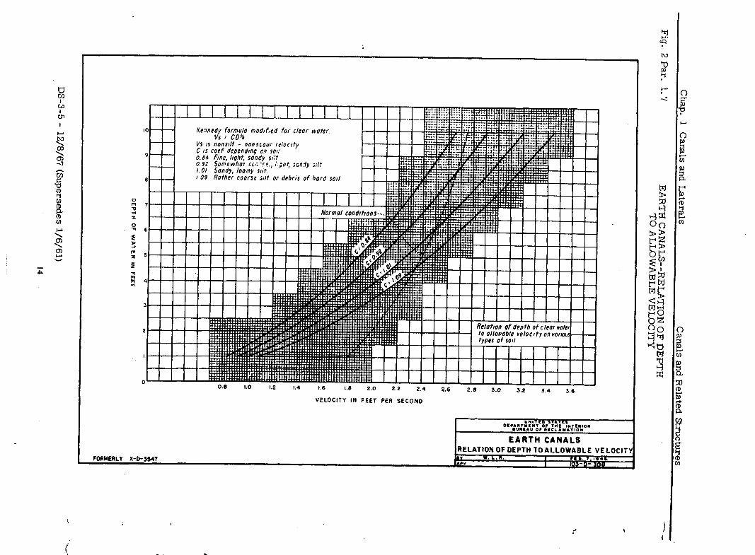
Operation and maintenance problems should be considered in the selection of canal cross-section characteristics, such that an overall economy of initial cost and maintenance expense may be obtained. Figure 2 is a curve showing suggested nonsilt, nonscour velocities for clear water running in canals. These velocities ordinarily require modification in Bureau designs due to the variability of soils and sediment in the water. (See Paragraph 1.12. ) Fig- ures 3A and 3B include tables of typical earth sections for irrigation canals with l-1/2:1 and 2:l inside slopes, respectively.
.8 A canal should divert from a supply source at sufficient elevation (static or pumped) to reach, with proper gradiert- * land to be irrigated.
1 3 .ind by the most economic route, the The water section may, at various points along the
canal, be partially or entirely in either cut or fill, depending on the location selected to satisfy requirements o f safety, structural design, distribution, and least annual cost includina maintenance. If the water section is partially or entirely in fill, consideratcon should be given to the use of compacted em- bankments or other suitable means of preventing excess seepage and percola- tion through the fill. At turnouts the canal water surface must be high enough to permit irrigation of the land. .
CROSS SECTION
LOCATION
.9 The allowable curvature for unlined canals depends on the size or capacity, CURVATURE velocity, soil, and canal section. A small lateral, 20 cfs or less in capzc- AND ity, flowing at low velocity, 2 feet per second or less, will require only a VELOCITY very small radius of curvat’ure. A large canal, 2,500 cfs or more in capac- ity, will require a much larger radius regardless of the velocity.
Velocities in unlined canals ordinarily vary from 1.0 to 3.5 feet per second. Whiie not an extreme mathematical variable, velocity does have appreciable
DS-3-5 - 12/8/67
3
1. 10
Chap. 1 Canals and Laterals Canals and Related Structures -
UNLINED CANALS OR LATERALS--Continued .:’
CURVATURE AND
VELOCITY (Cont’d. )
influence on the radius of curvature required. Water flowing at a velocity of 3.5 feet per second will cause more erosion and develop larger waves than water flowing at 1.0 feet per second around the same radius curves.
The character of the soil has a decided influence on the radius of curvature required. Soil may range from firm to shifting, and its stability may be quite sensitive to the curvilinear flow of the water. -
i In order to develop a satisfactory rule for determining the radius of curvature required, it is necessary to establish some ratio or ratios of radius of curva- ture to dimensional elements of a canal section. Since the factors already discussed vary simultaneously with dimensional elements, it is possible to establish such ratios only within general limits. A suggested rule is that the radius to the canal centerline should be from three to seven times the water surface width (the larger ratios for the larger capacities), depending upon the size or capacity of the canal, the soil characteristics, and the velocity. Con- sideration of all factors is required for an acceptable solution.
r
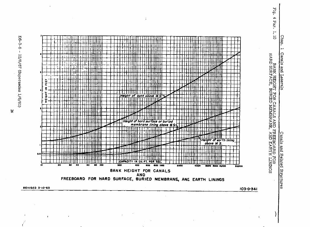
FREE- . 10 Freeboard in a canal will normally be governed by considerations of the canal BOARD size and location, velocity, storm-water inflow, water-surface fluctuations
caused by checks, wind action, soil characteristics, percolation gradients, operating-road requirements., and availability of excavated material. The typical earth sections listed 111 Figures 3A and 3B include the recommended minimum freeboard, and the height of bank above the water surface as shown in Figure 4 may also be used as a guide. These illustrations are based upon average Bureau practice, and it is emphasized that they will not necessarily serve for all conditions. Greater bank heights than those needed for hydraulic reasons may be used where excess excavation exists, provided that undesir- able conditions with respect to right-of-way, maintenance, structures, and
. . design elements are not thereby introduced; in the latter event the excess material should be disposed of in some other manner. The use of excessively high banks, particularly on sidehills, increases the hazard of bank sloughing.
BANE TOP WIDTH’
11 Banks used as operation and maintenance roads may range from 12 feet wide for canals with a capacity of 100 cfs to 20 feet and wider for canals with a
AND capacity of 2,500 cfs or more. Access to waterways should always be pro- BERM vided and is usually accomplished by an operating road on the bank. Where
the operating road is not on the bank, the width of bank may be as small as 3 feet for the small laterals. If borrow material is required to build canal or lateral banks, such borrow should be kept to a minimum and the borrow pits should be drained. Operation and maintenance roads should be located at a minimum height above the water surface, to facilitate maintenance of the canal.
Berms reduce bank loads which may cause sloughing of earth into the canal set tion. Steeper slopes may be used above the berm, provided the material is stable.
Canal and lateral banks should be finished so that, even where there are no regular operating roads, the lines of the bank are regular enough to permit the use of power mowers and other power equipment to control the growth of weeds and maintain the canal sections.
Waste banks and cuts should be made to blend with the surrounding terrain where possible. Every effort should be made to obtain an appearance which does not disrupt :i~d naturai terrain and beauty.
FLOW FORMULAS *
12 The Manning formula is generally used for open-channel flow. The formula is as followz~
4
- -
DS-3-5 12/8/67
Canals and Related Structures Chap. 1 Canals and Laterals
1.12
UNLINED CANALS OR LATERALS--Ccntinued
3
t - 1.486 ,a& n
where
V = velocity of water in feet per second, s = slope of energy gradient in feet per foot, r = hydraulic radius (water area divided by
wetted perimeter), and n = coefficient of roughness.
A roughness coefficient “n” of 0.025 is generally used for earth canals with capacities less than 100 cfs and 0.020 or 0.0225 for larger canals. Recom- mended coefficients of roughness are given in the Bureau’s Hydraulic and Excavation Tables.
For uniform channel sections covered with sand and gravel, the Manning’s “I-I” may be determined by the Strickler equation,
n = 0.0342 d 50 l/e
where ciiO equals the size in feet for which 50 percent of bed material by weight is finer.
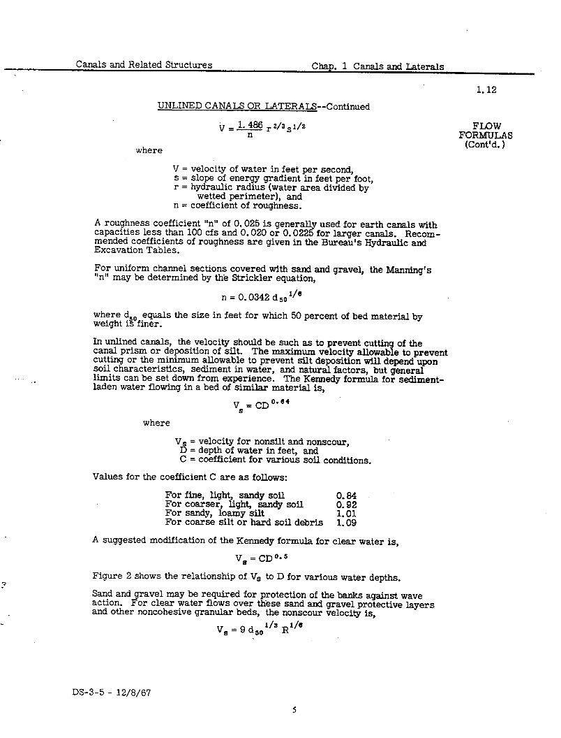
In unlined canals, the velocity should be such as to prevent cutting of the canal prism or deposition of silt. The maximum velocity allowable to prevent cutting or the minimum allowable to prevent silt deposition will depend upon soil characteristics, sediment in water, and natural factors, but general limits can be set down from experience. The Kennedy formula for sediment- laden water flowing in a bed of similar material is,
where
VS = velocity for nonsilt and nonscour, D = depth of water in feet, and C = coefficient for various soil conditions.
Values for the coefficient C are as follows:
For fine, light, sandy soil 0.84 For coarser, light, sandy soil 0.92 For sandy, loamy silt 1.01 For coarse silt or hard soil debris 1.09
A suggested modification of the Kennedy formula for clear water is,
V, = CD0m5
Figure 2 shows the relationship of V, to D for various water depths.
Sand and gravel may be required for protection of the banks against wave action. For clear water flows over these sand and gravel protective layers and other noncohesive granular beds, the nonscour velocity is,
Vs = 9 d50’/J $I6
DS-3-5 - 12/8/67
FLOW FORMULAS
(Cont’d. 1
1.13
Chap. 1 Canals and Laterals Canals and Related Structures
UNLINED CANALS OR LATERALS--Continued
FLOW FORMULAS
(Cont’d. 1
After a channel is in operation for an extended period, heavy concentrations of fine sediments in the flow may cause cementing (cohesion) of some fine sands in the bed. This often results in an increase in the nonscour velocities of up to 50 percent.
.
Bureau canal designs are based on the capacity required to supply the maxi- mum lo-day demand period. This results in canals and laterals being oper- ated for most of the year at below design capacity and usually with checks to make deliveries. Because of this, any sediment above colloidal size in the supply water will have to be excluded from the headworks or removed some- where from the system. Thus canals and laterals are usually designed to avoid scour at maximum discharge, and some provision is made to remove or exclude the sediment at the headworks or remove it from certain reaches of the canal. In transport canals to powerplants or offstream reservoirs, adequate sediment-carrying ability should be provided.
HYDs%X;LIC .13 Hydraulic bore, which is discussed briefly under Subparagraph 1.23A, may occur in unlined canals. It may be caused by the shutdown of a pumping plant, rapid closure of a check or gate, or as a result of sudden inflow causing a wave in the canal.
LINED CANALS OR LATERALS
DEFINITION .14 Lined canals or laterals may be divided into three groups: hard surface, buried membrane, and earth linings. Hard-surface linings include portland cement concrete linings, shotcrete linings, asphalt concrete linings, exposed prefabricated asphait linings, brick linings, stone linings, exposed plastic linings, soil-cement linings, and precast concrete linings. Buried-membrane linings include sprayed-in-place asphalt, prefabricated asphalt, plastics, and bentonite. Earth linings include thick compacted earth, thin compacted earth, lcosely placed earth, and bentonite soil mixtures. For information on canal linings see current edition of the Bureau publication “Linings for Irrigation Canals. ”
CROSS .15 Cross Section. SECTION
Hard-surface Linings
I
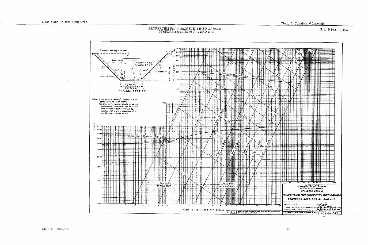
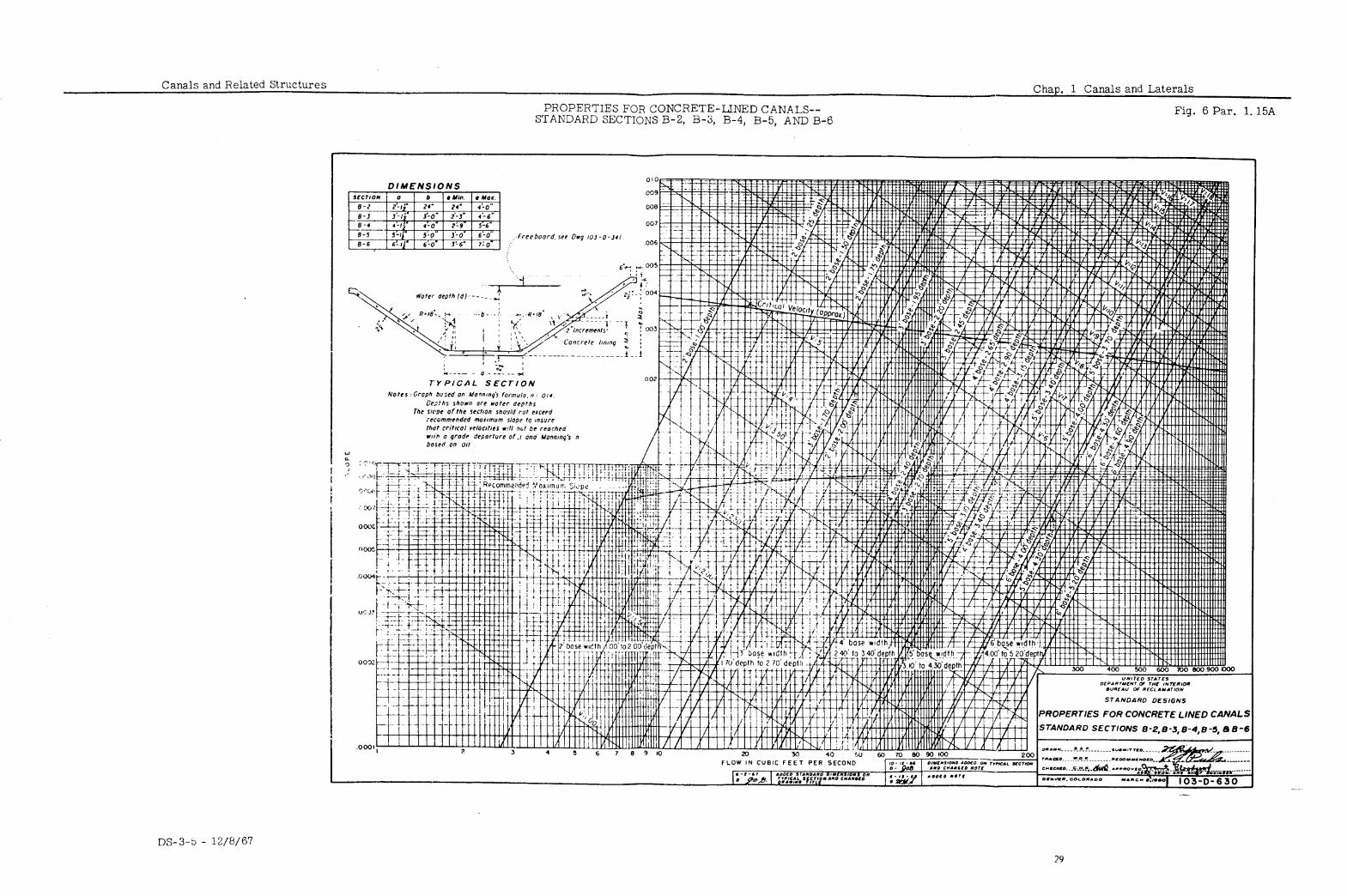
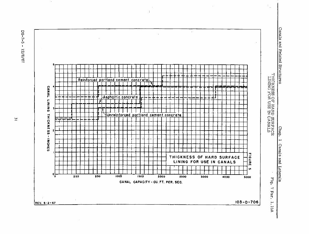
A. Since the cost of ‘i hard-surface lining usually amounts to a large per- centage of the total cost of constructing a iined canal, the section with the least perimeter is the most economical. A semicircle has the small- est perimeter for a given area, but a semicircular section is not practi- cal because the top portions of the sides are too steep. From experience, the steepest satisfactory side slopes for most large canals from both con- struction and maintenance considerations are l-1/2: 1. Steeper slopes may be used on small laterals where the soil materials will remain stable. Hard-surface-lined canals are usually designed with a ratio of base width to water depth of from 1 to 2. Small canals normally have a ratio of nearly 1, while the ratio for large canals may exceed 2. Figures 5 and 6 show standard dimensions and hydraulic properties for small canals with concrete lining. Figure 7 shows normal lining thickness.
The location of the canal bottom with respect to the ground-water table is especially important. If the ground-water table is above the canal bottom, outside hydrostatic pressure may rupture the lining when the canal is emptied or the water surface drawn down. In cold climates the canal bottom must be at least 3 feet above the water table to prevent dam- age from freezing and thawing. In soils having high capillarity a greater distance above water table is advisable. If hard-surface lining is used
.’
-..__- i
DS-3-5 - 12/8/67
Canals and Related Structures Chap. 1 Canals and Laterals
1.15B . . . . LINED CANALS OR LATERALS--Continued
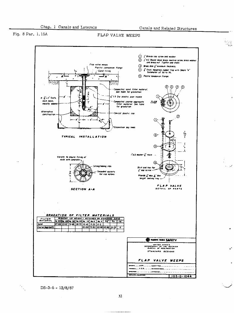
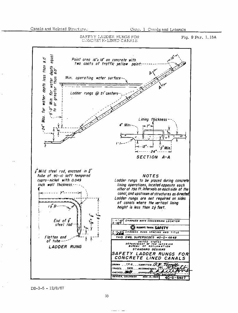
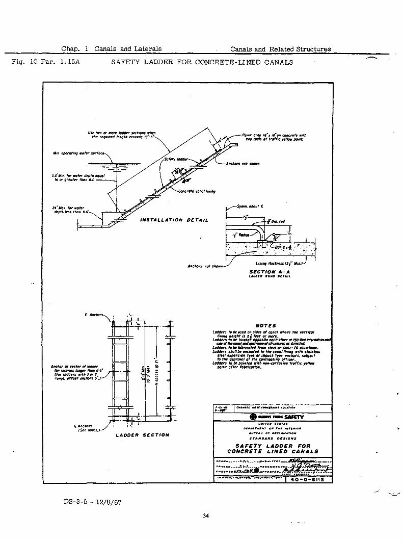
with high ground water, gravel or tile and gravel underdrains with suit- Hard-surface able outlets must be‘provided to reduce the probability of damaging the lining. Figure 8 shows a flap valve drain outlet for use with a hard- surface lining. The lining must be placed against a stable foundation of existing or compacted material. If expansive clay is present, the treat: ment consists of overexcavating and replacing with a minimum of 2 feet of nonexpansive material or maintaining a near saturated foundation un- til the lining is placed. The expansive characteristics of the material will determine the load necessary to confine it. In reaches where ex- pansive clay or high ground water exists, consideration should be given to omitting the lining or relocating the canal. Figures 9 and 10 show typical safety ladders for concrete-lined canals.
B. Buried-membrane lining is normally installed only to reduce water loss Buried- by seepage. A cover must be provided to protect the membrane from membrane exposure to the elements.and from injury by turbulent water, stock, plant growth, and maintenance equipment. The depth of cover depends
Linings
on cover material, size of canal, water velocity, and canal side slopes. Gravel is generally required at the beach belt in larger canals for pro- tection against wave action. The canal bottom width should be aboilt four times the water depth or greater and the side slopes 2: 1 or flatter. Long- radius curves are desirable at the intersection of the side slopes and the bottom to improve stability and to more nearly approach the final shape of the canal section after it has been in operation. When rounded uni- formly graded gravels or sands have been used for cover material, 2:l side slopes have proved to be too steep. There is also danger that the cover material may slough down the bank during placing. Such sloughing may carry the membrane down the slope with it, causing it to crack or tear. Flatter side slopes and placing the cover material on the canal bottom and lower portions of the side slopes first, may prevent damaging the membrane lining. At structures the membrane should be carefully bonded to the cutoff and should be lowered a sufficient distance away from the structure to provide space for extending riprap protection where required. Laboratory tests of the available cover material are desirable in determining the side slopes and mixtures of available mate- rials to be used for best results. Crushed rock or angular cover mate- rial should never be placed directly on the membrane because of the danger of puncturing it. Earth, gravelly material, and gravel have been used for cover over membrane linings. A small amount of lean clay will add stability, especially to gravelly materials and gravel. See Figure 11 for details of buried-membrane lining.
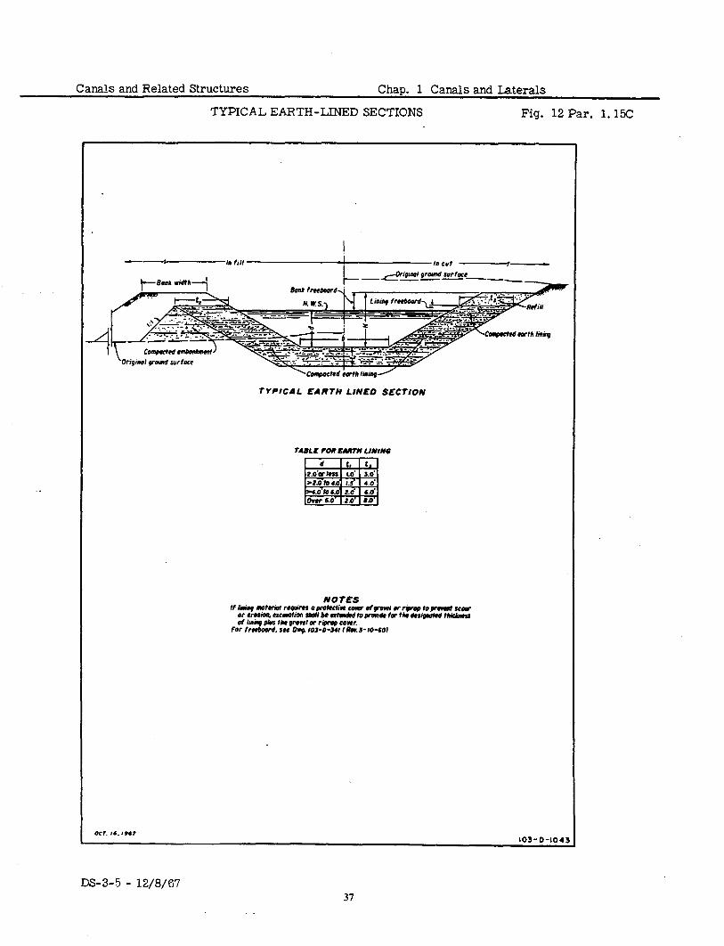
C. Earth linings normally have a 3- to 8-foot thickness on the canal sides, Earth measured horizontally, and a 12- to 24-inch bottom thickness of com- pacted select material. However, any compacted section 12 inches thick
Linings
or more is considered to be thick compacted earth lining. shows typical earth-lined sections.
Figure 12 Thin compacted earth linings usually
have a 6- to 12-inch layer of compacted cohesive soil with a protective cover of 6 to 12 inches of coarse soil or gravel. Loosely placed earth lining generally consists of a loose earth blanket of selected fine-grained soils dumped into the canal and spread over the bottom and sides to a thickness of about 12 inches. Bentonite soil mixtures usually consist of a sandy soil and bentonite mixed together and compacted. The thickness varies with local conditions. The bottom width to depth ratio and side slopes should be about the same as for unlined sections discussed in Paragraph 1.7.
.16 The location requirements for lined canals are about the same as for unlined LOCATION canals discussed in Paragraph 1.8, but a lined canal may economically fol- low a more direct route.
DS-3-5 - 12/8/67
1.17
Chap. 1 Canals and Laterals Canals and Related Structures
CURVA- ,17 TURE AND VELOCITY
. .
FREE- .18 BOARD
BANE TOP .19 WIDTH AND
BERM
FLOW .20 The Manning formula, which is generally used for open-channel flow, is pre- FORMULAS sented and discussed in Paragraph 1.12.
Manning’ s Roughness Coefficient
A. Values of the MIxming roughness coefficient “n” used in design for most lined canals are as follows:
LINED CANALS OR LATERALS--Continued
The allowable curvature for lined canals depends on the size and capacity, velocity, material used for lining, and the canal section. Hard-surface lin- ings permit higher velocities than earth sections. Usually these velocities should be less than 8 feet per second to avoid the possibility of converting velocity head through a crack to pressure head under the lining and lifting the lining. A mathematical check using an “n” value of 0. CO3 less than the design “n” used for the lining is also required to make certain the depth of flow does not approach critical depth closely enough to develop standing waves at sections where the bottom might be raised above theoretical grade due to construction tolerances.
Buried-membrane linings are usually covered with available material using thickness and canal section changes as required for stability. Velocities which are permissible in ordinary earth canals, where some erosion can be tolerated, may be too high for a buried-membrane lining where shallow scour may entirely remove the protective cover material from buried membrane. It must be realized that for a given velocity clear water may scour, while water carrying considerable sediment may build sandbars, with all other canal conditions being the same. From experience, it appears that the maxi- mum velocity for buried-membrane-lined canals of a given size and shape is about two-thirds of that permissible for unlined earth canals in similar mate- rials (see Paragraph 1.9). The permissible velocities in earth-lined canals vary with the type of lining and material, and usually range from 1 to 4 feet per second.
All influencing factors must be considered in determining the minimum radius of curvature. A suggested guide is that the minimum radius to canal center- line should be from three to seven times the water surface width if erodible linings are used. The smaller ratio is normally used for small canals while the larger ratio is needed for large canals. A concrete-lined canal should have a minimum radius of three times the water surface width.
Freeboard for lined canals will depend upon a number of factors, such as the size of canal, velocity of water, curvature of alinement, storm water enter- ing the canal, wind and wave action, and anticipated method of operation. The normal freeboard varies from 6 inches for small laterals to 2 feet or more for large canals. Figure 4 represents average Bureau practice as a guide for determining minimum freeboard and bank height for canals with hard-surface, buried-membrane, and earth linings.
The height of canal bank above the top of the lining usually varies from 6 inches for small laterals to over 2 feet for large canals. (See Figure 4. )
.A 2- to g-foot berm is normally provided at the top of hard-surface linings for the construction convenience of trimming and lining machinery. Backfill should be placed on this berm from the top of the lining and sloping upward to the earth bank, to prevent surface drainage from entering the subgrade behind the canal lining. The top width of canal banks and berms for lined canals should be about the same as for unlined canals discussed in Para- graph 1.11.
DS-3-5 - 12/8/67
Canals and Related Structures Chap. 1 Canals and Laterals
1.20B
LINED CANALS OR LATERALS--Continued
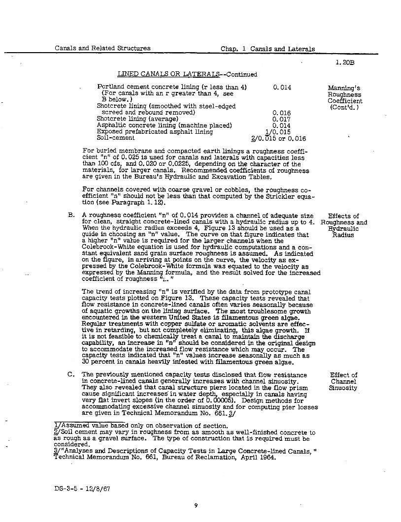
Portland cement concrete lining (r less than 4) 0.014 (For canals with an r greater than 4, see B below. )
Shotcrete lining (smoothed with steel-edged screed and rebound removed) 0.016
Shotcrete lining (average) 0.017 Asphaltic concrete lining (machine placed) 0.014 Exposed prefabricated asphalt lining Soil-cement 2/O. ~~-:I%. 016
For buried membrane and compacted earth linings a roughness coeffi- cient “n” of 0.025 is used for canals and laterals with capacities less than 100 cfs, and 0.020 or 0.0225, depending on the character of the materials, for larger canals. Recommended coefficients of roughness are given in the Bureau’s Hydraulic and Excavation Tables.
Manning’ s Roughness Coefficient (Cont’d. )
For channels covered with coarse gravel or cobbles, the roughness co- efficient “n” should not be less than that computed by the Strickler equa- tion (see Paragraph 1.12).
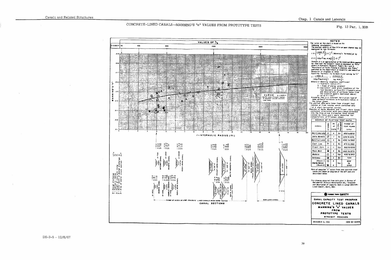
B. A roughness coefficient “n” of 0.014 provides a channel of adequate size Effects of for clean, straight concrete-lined canals with a hydraulic radius up to 4. When the hydraulic radius exceeds 4, Figure 13 should be used as a
Roughness and
guide in choosing an ‘In” value. The curve on that figure indicates that Hydraulic
Radius a higher “n” value is required for the larger channels when the Colebrook-White equation is used for hydraulic computations and a con- stant equivalent sand grain surface roughness is assumed. As indicated on the figure, in arriving at points on the curve, the velocity as ex- pressed by the Colebrook-White formula was equated to the velocity as expressed by the Manning formula, and the result solved for the increased coefficient of roughness “t. ”
The trend of increasing “n” is verified by the data from prototype canal capacity tests plotted on Figure 13. These capacity tests revealed that flow resistance in concrete-lined canals often varies seasonally because of aquatic growths on the lining surface. The most troublesome growth encountered in the western United States is filamentous greeri algae. Regular treatments with copper sulfate or aromatic solvents are effec- tive in retarding, but not completely eliminating, this algae growth. If it is not feasible to chemically treat a canal to maintajn the discharge capability, an increase in “ntt should be considered in the original design to accommodate the increased flow resistance which may occur. The capacity tests indicated that “n” values increase seasonally as much as 30 percent in canals heavily infested with filamentous green algae.
C. The previously mentioned capacity tests disclosed that flow resistance Effect of in concrete-lined canals generally increases with channel sinuosity. Channel They also revealed that canal structure piers located in the flow prism cause significant increases. in water depth, especially in canals having
Sinuosity
very flat invert slopes (in the order of 0.00005). Design methods for accommodating excessive channel sinuosity and for computing pier losses are given in Technical Memorandum No. 661.2
lJAssumed value based only on observation of section. 2JSoil cement may vary in roughness from as smooth as well-finished concrete to as rough as a gravel surface. considered.
The type of construction that is required must be
3J”Analyses and Descriptions of Capacity Tests in Large Concrete-lined Canals, ‘I Technical Memorandum No. 661, Bureau of Reclamation, April 1964.
DS-3-5 - 12/8/67
Chap. 1 Canals and Laterals Canals and Related Structures
1.21
LINED CANALS OR LATERALS--Continued
HYDRAU - LIC BORE
WINTER OPERA -
TION
. .
POWER CANALS
Hydraulic Bore
DRAINAGE SYSTEMS
.21 Hydraulic bore, which, is discussed briefly under Subparagraph 1.23A, may occur in lined canals. It may be caused by the shutdown of a pumping plant, rapid closure of a check or gate, or as a result of a sudden inflow causing a wave in the canal.
. 22 The primary difficulty in winter operation is the accumulation of frazil ice in the canal, especially at the inlets to structures such as siphons or penstocks.
Winter operation can be maintained by designing the system for one of two methods of operation:
A. To be operated at a capacity sufficient to prevent freezing. This pre- sumes that the water temperature at the headworks is sufficiently above freezing to offset the heat loss in the canal. -
B. If the first alternative is not feasible, the canal should be designed for operation under an ice cover. than 2.2 feet per second.
A cover forms readily at velocities less Further, frazil ice rises to form surface ice
at velocities less than 2 feet per second. further heat loss is virtually eliminated.
Once an ice cover is formed, * The design and operation may
be greatly simplified if uniform flow is maintained during the winter months.
.23
In either case, abrupt changes in grade or alinement should be avoided, as turbulence is essential to frazil ice production.
In the design of a power canal for winter operation, consideration should be given to the value of head that can be saved by using a velocity of 2 feet per second on a flat slope. The saving in head may offset the first cost of the larger canal section.
OTHER WATER WAYS
Power canals convey water from the sources of supply to the penstocks of powerplants. The primary difference between power and irrigation canals is the purpose to be accomplished. The value of power produced should be con- sidered in determining the most economical canal section. Power canals will usually have more sudden changes in flow than irrigation canals. Waste- ways are generally required just upstream from the powerplant, and the hy- draulic bore must be computed in order to provide adequate freeboard on the Cd.
A. A hydraulic bore is caused by a sudden change of discharge at any point in an open channel. It results in a moving wave going upstream or down- stream in the channel. If the wave is caused by suddenly’stopping the flow of water in a channel, as is the case in a powerplant shutdown or rapid closure of a check or gate, the hydraulic bore will travel upstream at a high velocity. The momentum, pressure, volume, and gravity ef- fect must all be considered in computing the characteristics of the wave and its effect upon the channel. The downstream leveling of the water surface that occurs after the bore wave has passed must also be eval- uated to determine the maximum rise in the water surface.
.24 The purpose of a drainage system is to remove excess water .from the ground surface or subsoil. A drainage system may be required to prevent water- logging of the land due to precipitation, irrigation waste, canal seepage, or high ground-water table. The possible need for a drainage system should
DS-3-5 - 12/8/67 IO
Canals and Related Structures \ Chap. 1 Canals and Laterals
1.25
OTHER WATER WAYS--Continued
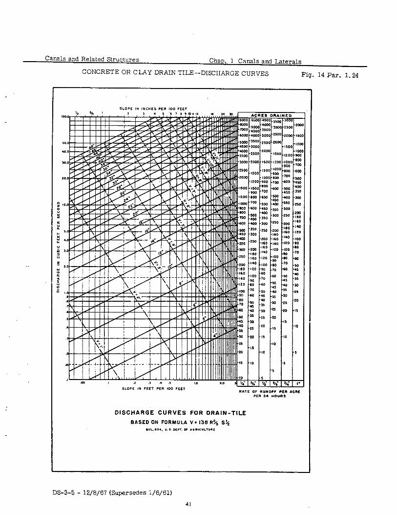
always be considered with the desigqof an irrigation system. Open or under- DRAINAGE ground drains or a combination thereof may be used to effect an economical system to serve the needs of the area. The general design requirements for ?i::tE:: I . open drains are similar to those for irrigation channels. Open-joint tile pipe as well as closed-joint pipe may be used in underground drains. ure 14 for discharge curves for concrete or clay drain tile.
See Fig-
.25 Wasteway channels are sometimes required to dispose of excess water in WASTEWAY canals. They are needed to dispose of operational waste or floodwater that CHANNELS has entered the canal, or to empty the canal. The general requirements for wasteway channels are similar to those for irrigation channels, depending on local conditions. Owing to infrequent use of wasteway channels at full capac- ity, the allowable velocity at full flow is usually greater than for an irrigation canal of similar capacity.
DS-3-5 - 12/8/67
II
1
w
s-0 G At Rood width wncrr E ,*’ OGM Rood is rcqvrrrd I
IN THOROUGR CUT IN FILL OR PART FILL
TYPICAL SECtION
TYPICAL UNLINED SEOTION FOR CANALS AND LATER’ALS
10
Vs 15 nonsdt - nonstoui wiocfty
9
ti 1 i ii ”
0.6 1.0 1.2 1.4 1.6 1.6 2.0 2.2 2.4 76 3R in x0 II .c
VELOCITY IN FEET PER SECOND
UNlTrsmrn DCC.II”C”~ 0, I”L I”IL”l0”
.““I.” 0, RsCL.Y.IIQ*
EARTH CANALS RELATION OF DEPTH TO ALLOWABLE VELOCIT’ u . . . I ..I .PY I - -
L
. , \. , .a ,
.*
z -
Canals and Related Structures Chap. 1 Canals and Laterals
.
. .
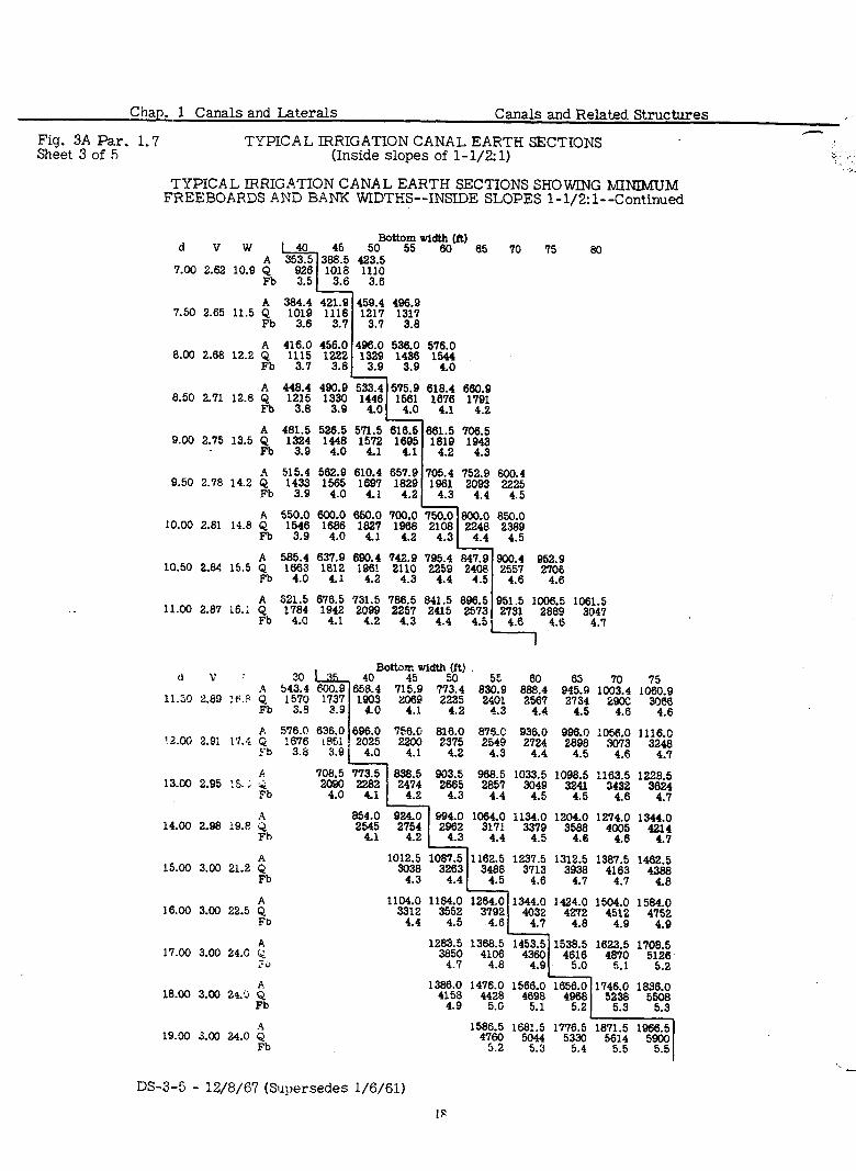
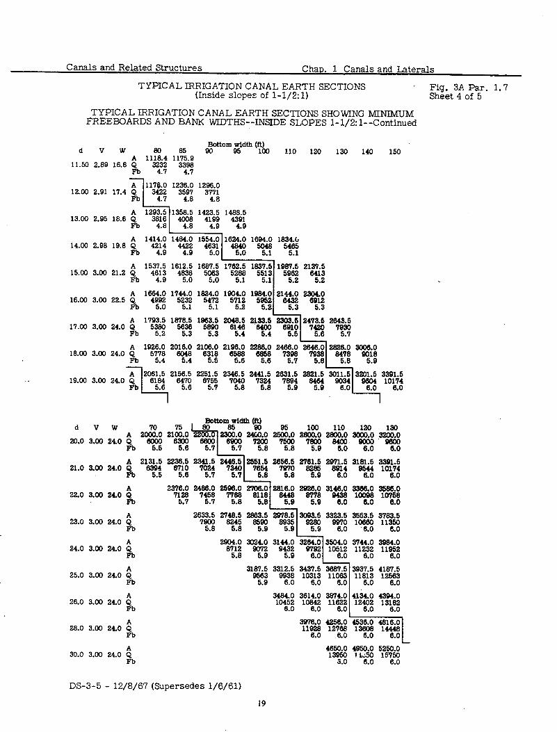
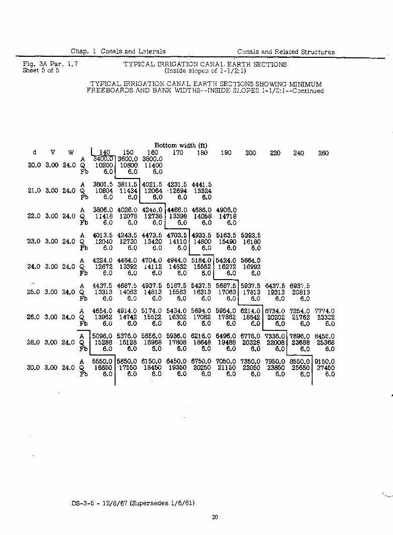
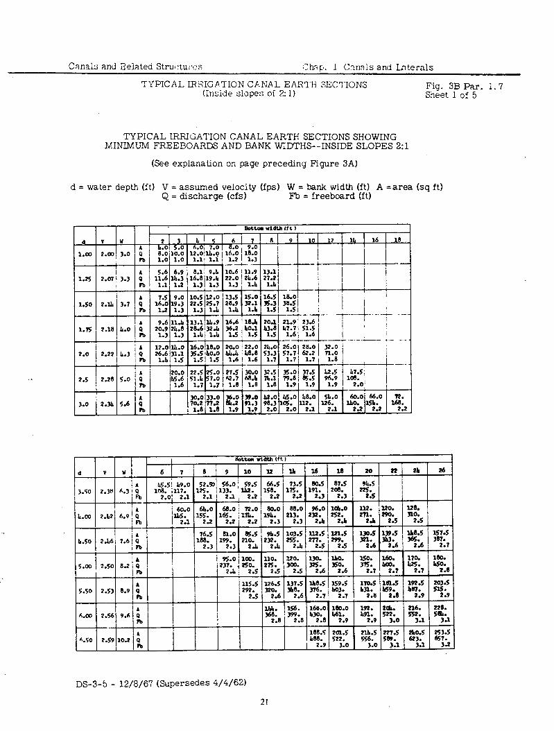
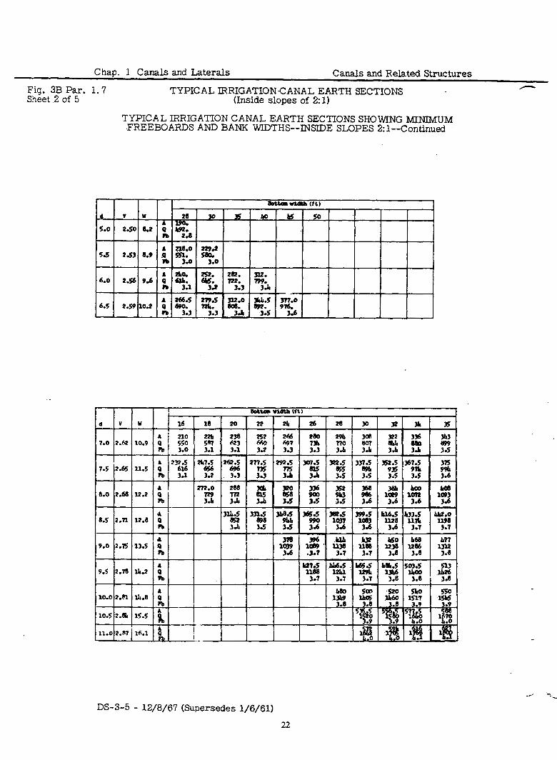
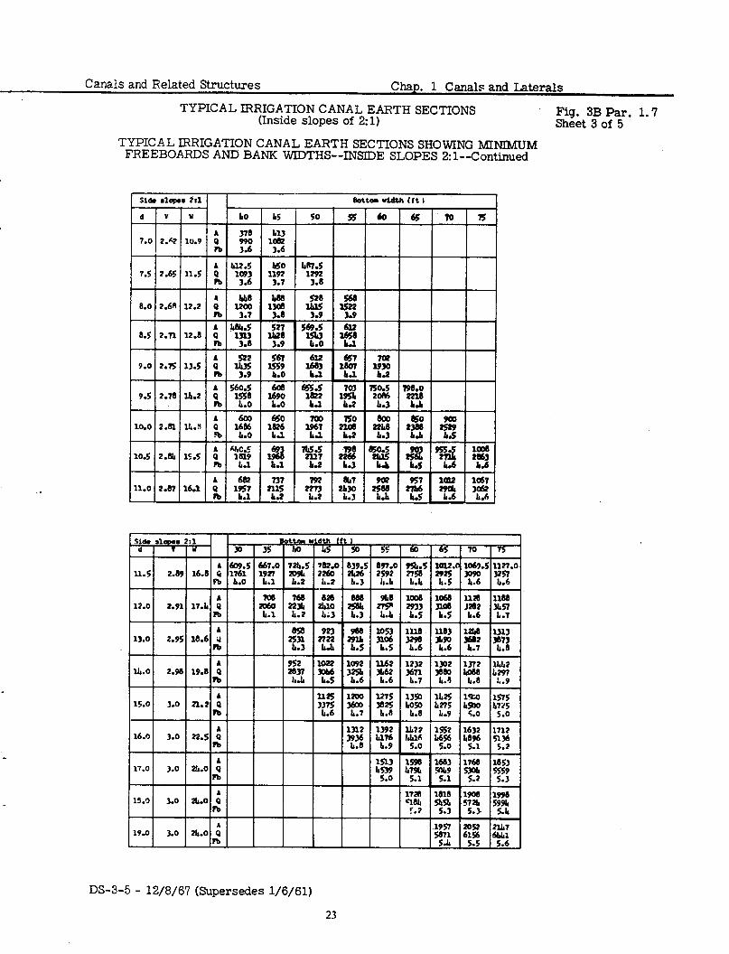
IRRIGATION CANAL EARTH SECTIONS--INSIDE SLOPES l-1/2:1 and 2:l.
(An explanation of the tables shown as Figures 3A and 3B)
General
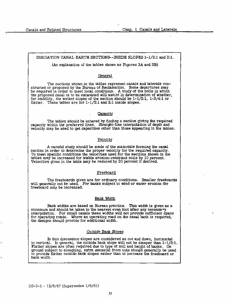
The sections shown in the tables represent canals and laterals con- structed or proposed by the Bureau of Reclamation. Some departures may be required in order to meet local conditions. A study of the soils in which the proposed canal is to be excavated will assist in determination of whether, for stability, the wetted slopes of the section should be l-1/2:1, l-3/4:1 or flatter. These tables are for l-1/2:1 and 2:l inside slopes.
Caoaci ty
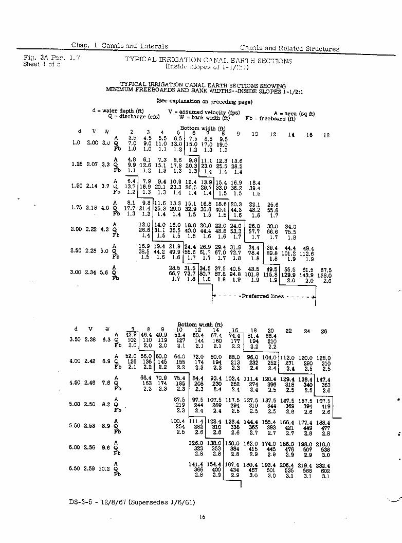
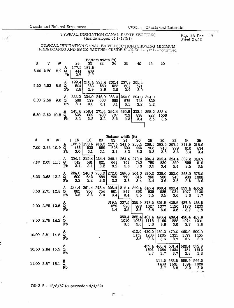
The tables should be entered by finding a section giving the required capacity within the preferred lines. Straight-line interpolation of depth and velocity may be used to get capacities other than those appearing in the tables.
Velocity
A careful study should be made of the materials forming the canal section in order to determine the proper velocity for the required capacity. To meet specific conditions the velocities used for the sections shown in the tables may be increased for stable erosion-resistant soils by 10 percent. Velocities given in the table may be reduced by 20 percent if desired.
Freeboard
The freeboards given are for ordinary conditions. Smaller freeboards will generally not be used. For banks subject to wind or water erosion the freeboard may be increased.
Bank Width
Bank widths are based on Bureau practice. This width is given as a minimum and should be taken to the nearest even foot after any necessary interpolation. For small canals these widths will not provide sufficient space for operating roads. Where an operating road on the canal bank is required, the designs should provide for additional width.
Outside Bank Slopes
In this discussion slopes are considered as out and down, horizontal to vertical. In general, the outside bank slope will not be steeper than l-1/2:1. Flatter slopes are often required due to type of soil and height of banks. On ground subject to sloughing, extra material from cuts should generally be used to provide flatter outside bank slopes rather than to increase the freeboard or bank. width.
DS-3-5 - 12/8/67 (Supersedes l/6/61)
15
Chap. 1 Canniu and Lrterals ‘C3mls arid I?&ted Structures
Fief. 3A ?ar. 1. ‘I Sheet ! af 5
TYPICAL lRi?IG.4?‘10N C.l?f‘i.A,I. EzZHl I-f SEC?‘IONS (Insid<. :J~I:YJ~)c~ tif i-i/:!: .I )
TYPICAL IRRIGATION CANAL EARTH SECTIONS SHOWING MINIMUM FREEBGAFDS Ah3 BANK WIDTHS--INSIDE SLOPES l-1/2:1
(See explanation on preceding page)
d = water depth (ft) Q = discharge (cfs)
V = assumed velocit (fps) W = bank width ft) I
A = area (sq ft) Fb = freeboard (ft)
.
d v w 325 3 545 5 Bottom width (ft
15:o 765 17:o 8’5 d
$ 9 4.5 10 6 5 12 14 16 18 1.0 2.00 3.u 7.0
9.0 11.0 1310
Fb 1.0 1.0
19’0 9 5
1.1 1.2 1.2 1.3 1:3
3.3 $ 4.8 1.25 6.1 2.07 7.3 8.6 9.8 9.9 I 11.1 .12.6 15.1
12.3 13.6 17.8 20.3
Fb 23.0
1.1 1.2 25.5 28.2
1.3 1.3 1.3 1.4 1.4 1.4
9.4 10.9 12.4 13.9 15.4 20.1 23.3 26.5 29.7 33.0 1 1.3 1.4 1.4 1.4 1.5
1.50 2.14 3.7 ib 1;:; -L $3 . .
1.75 2.18 4.0 ib 1;:; 2f:i - .
2.00 12.0
2.22 4.3 $ Fb 2!:f
11.6 13.3 15.1 16.8 18.6 25.3 29.0 32.9 36.6 40.5
1.4 1.4 1.5 1.5 1.5
16.9 18.4 36.2 39.4
1.5 1.5
20.3 22.1 25.6 4f.i 4y6 5t.;
if.” .I 35.5 16.0 40.0 18.0 20.0 44.4 22.0 24.0 26.0 30.0 48.8
34.0 53.3 1.5 1.5 66.6 1.5 1.6 75.5 1.6
1.7
I “7.;
. 1.7 1.8
2.50 2.28 5.0 ; 16.9
Fb “2
3.00 2.34 5.6 ; Fb ---- -Preferred lines - - - - -
d V W Bottom width (ft)
3.50 2.38 6.3 Q
4.00 2.42 6.9 Q 8;9: 8$ti$ 9;&; lO;k;
2.3 2.3 2.4 2.4
4.50 2.46 ij 6;6f ‘pi; 7l58; 84.4 7.6 93.4 102.4 111.4 120.4
252 Fb 2.2 2.3 2.3 “2”: . “2”: . 2.4 :7: . ig: .
5.00
g7.5
2.50 8.2 $ ‘ii; Fb 2.3 L “z’t .
5.50 2.53 8.9 $ 100.4 ‘111.4
254 282 Fb 2.5 2.6
6.00 2.56 9.6 6 1236ii Fb 2.8
10;7& 11;7.; 12;7; 137.5
2.4 2.5 2.5 . i4z
?io4 2.6
138.0 353 2.8
14;6; 15;4.
2.8 2.9
2.6 2.6 2.6
133.4 144.4 155.4 166.4 17:X; 1888;
2.7 2.8 2.8
150.0 162.0 174.0 186.0 384 415 445 476 ‘98.& 2y&
2.9 2.9 2.9 2.9 3.0
18:6& 19$. 2Of53& 21$ 23ti;
3.0 3.0 3.1 3.1 3.1
DS-3-5 - 12/8/67 (Supersedes l/6/61)
16
22 24 26
Canals and Related Structures Chap. 1 Canals and Laterals
I _,: .A,,. . . TYPICAL IRRIGATION CANAL EP.RTH SECTIONS
(Inside slopes of l-1/2:1) Fig. 3A Par. 1.7 Sheet 2 of 5
TYPICAL IRRIGATION CANAL EARTH SECTIONS SHOWING MINTMUM FREEBOARDS AND BANK WIDTHS--INSIDE SLOPES l-l/2:1--Continued
d V W
5.00 2.50 8.2 $ Fb
A 199.4 210.4 221.4 232.4 5.50 2.53 8.9 Q 529 532 560 588 23i6; 262+:
Fb . 2.9 2.9 2.9 2.9 3.0
17t85 187 Bigtorn 5 $dth (f\) 35 40 45 50
444 469 2.7 2.7
I
A ‘222.0 6.00 2.56 9.6 Q 568
Fb 3.0
A 245.4 6.50 2.59 10.2 Q 636
Fb 3.2
d VW 1 16 18 20 Bot&m w;&th (ft)
26 28 30 32 34 35 A 182i; 199.5 213.5 227.5 241.5 255.5 7.00 2.62 10.9 Q
Fb 3.0
532; 318.5 596 633 659 26;9; 28;i; 29;%; 3Ui; 834
.
535; . 3.1 3.2 3.2 3.3 3.3 3.3 3.4 3.4
A 204.4 7.50 2.65 11.5 Q 542
Fb 3.1 249.4 264.4 277940” 29$& 309.4 324.4 339.4 346.9
661 701 820 860 899 919 3.2 3.2 3.3 3.3 3.3 3.4 3.4 3.5 3.5
376.0
A 8.50 2.71 12.8 Q 24;4; 26;ti; 2778j; Fb 3.2 3.3 3.3
9.00 2.75 13.5 6 Fb
9.50 2.78 14.2 : Fb
29i6f 31;a; L 3.4 3.4 31g9ii 337.5 t2: 3.4 . 363.4
'03': .
329.4 346.4 363.4 380.4 397.4
899; . 939 3.5 985 3.5 1033; . 1077 3.6
355.5 373.5 391.5 409.5 427.5
;7,8 . 1032; . 1077 3.6 1126 3.6 1176 3.7
420.4 439.4 458.4 467.9 1169 1222 1274 1301
3.6 3.6 3.7 3.8
10.00 2.81 14.8 ; Fb
10.50 2.84 15.5 i$ Fb
11.00 2.87 16.1 $ Fb
450.0 470.0 490.0 500.0 1265 1321 1377 1405
3.6 3.7 3.7 3.8
459.4 1305
'3.7371 480.4 501.4 522.4 1364 1424 1484
3.7 3.8
511.5 533.5 555.5
1436; 1531 3.8 1594 3.9
405.9 1100
3.7 436.5 1200
3.8
532.9 1513
3.8
566.5 1626
3.9
DS-3-5 - 12/8/67 (Supersedes 4/4/62)
17
Chap. 1 Canals and Laterals Canals and Related Structures I
Fig. 3A -
Par. 1.7 TYPICAL IRRIGATION CANAL EARTH SECTIONS ’ Sheet 3 of 5 (Inside slopes of l-l/Z: 1) .: .~ .,. ,. .; :j :y.. .,._a..
TYPICAL IRRIGATION CANAL EARTH SECTIONS SHOWING MINIMUM FREEBOARDS AND BANK WIDTHS--INSIDE SLOPES 1-l/2:1--Continued
d VW A
- 35djo5 45 ,275 -O52 “‘%I’*’ 05 70 75 00 388 5
7.00 2.62 10.9 Q 9i6 lOi iii0 Fb 3.5 3.6 3.6
A 384.4 421.9 459.4 496.9 7.50 2.65 11.5 Q
Fb 103’; 1131; 1231; 1;1;
. . . .
A 8.00
416.0 456.0 496.0 536.0 576.0 2.68 12.2 Q
Fb 1\1; 1232; 1;2; 1;: 1%
. . . . .
A 8.50
448.4 490.9 533.4 575.9 618.4 660.9 2.71 12.8 Q
L?b 1231; l;? 144; 1546 ‘647; 1791
. . . 4.2 . .
A 9.00
481.5 526.5 571.5 616.5 861.5 706.5 2.75 13.5 Q
Fb 13;2; 1y; 1:: 1:9; ‘$1; 1yi
. .
A 9.50 2.78 14.2
515.4 562.9 610.4 657.9 705.4 752.9 800.4 Q 1433; l%j; ‘“49: 182; ly; 2093 2225 Fb . . . 4.4 4.5
A 10.00
550.0 600.0 650.0 700.0 750.0 800.0 850.0 2.81 14.8 Q
Fb ‘5j$6 1% 1827 1968 2’40; 2248 2348;
. . 4.1 4.2 . 4.4 .
A 585.4 637.9 742.9 795.4 847.9 10.50 2.84 15.5 Q
Fb
‘f%; ‘84’: 690.4 it!; 214; 2259 27; 900.4 “;5; 952.9 2700
. . 4.4 4.6 . .
A Il.00 2.87 16.: zb
S21.5 676.5 731.5 786.5 841.5 896.5 951.5 1006.5 174; ‘94: 2ff; 224; “‘a3
1061.5
3047 . . 4.7
l
.
c
3 ? -2
55 60 65
. 15.00 3.00 21.2 $
Fb
1104.0 1184.0 16.00
1264.0 3.00 22.5 : 3312
FO 4.4 3545;
. 3’4; .
1368.5 17.00 3.00 24.c : 12388; 4106
14:%& 1543ss;; 1623.5 1708.5
zti 4.7 4.8 4.9 5.0 4:7T . 515226 .
*-
18.00 3.00 2s.O $
Fb
19.00 3.00 24.0 : Fb
‘38X$ 1476.0 4420
4.9
15466; ‘64%; 175426 18;%3.&
5.0 5.1 5.2 5.3 5.3
1586.5 4760
16885 17;;; ‘8;iii I:&.&
5.2 5.3 5.4 5.5 5.5
DS-3-5 - I2/8/67 (Supersedes l/6/61)
d V W 80 85 90 Q*j'ti 100 110 120 130 140 Bottom (ft)
150 A lUl8.j ll;;i;
11.50 2.89 18.8 Q Fb 4.7 4.7
I 1176.0 1236.0 1296.0
12.00 2.91 17.4 Q 344; 354978 3771 . . 4.8
A 1423.5 1488.5 13.00 2.95 18.6 Q -1 12g93; 13:;; 4199 4391
Fb 4.8 4.8 4.9 4.9 A 14.00 2.98 19.8 Q 14$.. l44Mti; 15456:
'6z% 1694.0 1834.b
Fb 4.9 4.9 5.0 5.0 5?f %T . A 1537.5 1612.5 1687.5 1762.5 1837.5 1987.5 2137.5
15.00 3.00 21.2 Q 4:; y; y; 5;y 555'; 5;6; 64l; Fb.......
A 1744.0 1824.0 1904.0 1984.0 2144.0 2304.0 16.00 3.00 22.5 Q lz4.i 5;3: 5:7: 5751; 5:; M5q 69513
Fb 5.0. . . . . .
17.00 3.00 24.0 A 1793.5 1878.5 lQ63.5 2048.5 2l33.5 2303.5 2473.5 2643.5 Q 5z 5;; m59$I 6:4: E 6:; 742; 7;F Fb........
A 1926.0 2016.0 2106.0 2196.0 2286.0 2466.0 2646.0 2826.0 3006.0 18.00 3.00 24.0 Q 5;748 yi 6351: 6;y % 7359$ 79: 84jrt 9051;
Fb.........
23.0 3.00 24.0 : Fb
Canals and Related Structures Chap. 1 Canals and Laterals
TYPICAL IRRIGATION CANAL EARTH SECTIONS (Inside slopes of l-1/2:1)
. Fig. 3A Par. 1.7 Sheet 4 of 5
TYPICAL IRRIGATION CANAL EARTH SECTIONS SHOWING MINIMUM FREEBOARDS AND BANK WIDTHS--INSIDE SLOPES l-1/2: l--Continued
dVW
2633.5 2748.5 2863.5
7% % Y!t
24.0 3.00 24.0 : Fb
3187.5 3312.5 3437.5 3687.5 25.0 3.00 24.0 $
Fb 9;6; 9:; loss';
. 1106y
.
26.0 3.00 24.0 : Fb
28.0 3.00 24.0 : Fb
30.0 3.00 24.0 : Fb
3976.0 C256.0 fly0 12;6;
. .
6.0 6.0
3553.5 3783.5
1% . 11;: . 3744.0 3984.0
"i3i . % . 3937.5 4187.5
"881; . 12563 6.0
41i4.0 4394.0
12Z . 13i8i .
4650.0 4950.0 5250.0
1% It;? 15750 6.0
DS-3-5 - 12/8/67 (Supersedes l/6/61)
19
Chap. 1 Canals and Laterals Cmals and Related Structures
Fig. 3A Par. 1.7 TYPICAL IRRIGATION CANAL. EARTH SECTIONS Sheet 5 of 5 (Inside slopes of l-1/2:1)
TYPICAL GiRIGATION CANAL EARTH SECTIONS SHOWING MINIMUM FREEBOARDS 4ND BANK WIDTHS--INSIDE SLOPES l-l/2:1--Cmtinued
Bottom width (ft) d V W 1 140 150 160 170 180
3 00'36000 190 200 220 240 260
i$ I%260 lOti 38000
20.0 3.00 24.0 11460 Fb 6.0 6.0 6.0
A 3601.5 3811.5 4021.5 4231.5 4441.5 21.0 3.00 24.0 Q 'O;O; 11434 12064 .12694 13324
Fb . 6.0 6.0 6.0 6.0
A 3806.0 4026.0 424&O 4466.0 4686.0 4906.0 22.0 3.00 24.0 Q 12738
Fb lM61; 12078
. 6.0 6.0 133e9; 14718
. '""65;
. 6.0
A 4013.5 4243.5 4473.5 4703.5 4933.5 5163.5 5393.5 '23.0 3.00 24.0 Q
Fb 12064; l"'s3; 13420 16180
. . 6.0 14'S';
. 14;?
. 15"ss;
. 6.0 A 4224.0 4464.0 4704.0 4944.0
24.0 3.00 24.0 Q i4112 14832 Fb
12667i 13:9; . . 6.0 6.0 6.0
.
. . A 4437.5 4687.5 4937.5 5187.5 5437.5 25.0 3.00 24.0' Q 13313
Fb 6.0 14;6;
. 14:;
. l""$;;
. 163$;
.
A 4654.0 4914.0 5174.0 5434.0 5694.0 26.0 3.00 24.0 Q 13;6:
Fb. 14;$
. 157;
. 16360;
. 17068;
.
A 5096.0 1 Q 15268; 5376.0
5656.0 16;6; 5936.0 6216.0
28.0 3.00 24.0 Fb.
16y; . .
""60; .
18664; .
A 5550.0 1 166e5; 5850.0 6150.0 6450.0 6750.0 7050.0 7350.0 7950.0 8550.0 9150.0
30.0 3.00 24.0 Q 27450 'Fb .
17"65: .
18;5: .
19365: .
20;5: .
21;5: .
22;5; .
23\5; . 1 25650
6.0 6.0
.
DS-3-5 - 12/8/67 (Supersedes l/6/61)
20
Canals and Reiated Strul:tui.c:s i3hzp. 1 Annals and Lntcrals
TYPICAL IRKIGP’I‘ION CE.NAL EARTH SEC’:‘IONS (Inside slope:; of 2: 1)
Fig. 3B Par. 1.7 Sheet 1 of 5
TYPICAL IRRIGATION CANAL EARTH SECTIONS SHOWING MINIMUM FREEBOARDS AND BANK WIDTHS--INSIDE SLOPES 2:l
(See explanation on page preceding Figure 3A)
d = water depth (ft) V = assumed velocity (fps) W = bank width (ft) A =area (sq ft) Q = discharge (cfs) Fb = freeboard (ft)
btta width If t )
1.51 1.5 1.6 ) 1.6 1.7
!A 8.2iO ! ! 55.0 ~loo.
237. j2SO. 110.
5.00 2.50 t I* ZJb, 2.5 1 L 275.
2.5
I I IAl I I I 1115.5 1126.: 5.501 P.S3! 8.91: ! 1 1 1 /2~:sl"i";
Mu.0 leo.0
2.8 2.9 2.9 3.0 3.1 3.1 3
ll38.S 2ol.5 1 -- ! -- ! I
DS-3-5 - 12/8/67 (Supersedes 4/4/62)
21
Chap. 1 Canals and Laterals Canals and Related Structures
Fig. 3B Par. 1.7 TYPICAL IRRIGATION-CANAL EARTH SECTIONS Sheet 2 of 5 (Inside slopes of 2: 1)
TYPICAL IRRIGATION CANAL EARTH SECTIONS SHOWING MINIMUM .FREEBOARDS AND BANK WIDTHS--INSIDE SLOPES 2: l--Continued
I I d v Y 26 30 I 35 I Ilo I 16 I 50 I I '0
T 1 5.0 2.50 8.2 I
n
L90. rpz.
2.8
d 5s 2.53 6.9 FY z.? !
t 1
I 1 :; ml 3:o 3.0
I * I Iit 2m. n2.
,.l
z:
722. . 32 3.3 728 I".o! 2.56!9.6! ii i _
, not* ti#tb wt 1 I
d V Y
! IZi 16 20 22 2& 26 28 30 7.0 2.c 10.9 Q ^,I F2 2; z g ;g z z d i I*
' . 3.1 3.l 33 3.3 3.3 3+
/
3.h 3Jl 3.b 3.5
7.5 2.65 ll.5 : 'm& 2h7& 2622 277& m&5 3077 3222; 3374 35$2$
m.5
n 3.1 33 3.3 3.3 3A 3JI 3.5 3.5 3.5 3 . R .
'0 272.0 200
2.66 3ab Loo
0.0 l2.2 -1
E z z e 5 5 zj 3 'OR 3eh 35 . . 3.6
15 -- 1
8.5 .z.n 12.8 : 3LLs;: 3"& 3UJ& 3X5& ~W.& 39999; NfIf; bgg U2;;
n 3Jl 3.5 3.5 3d 34 36 3.6 3.7 3.7
9.0 2.75 13.5 : lz. l$ l% l%J
b69 W?
l2s
(9.5 jp.78!&.2 i;
.3.7 3.7 3.7 3.6 3.6 ';?I .
ll2n.J 3.7 l&6& 3.t II6565 3.T b(b.5 503.5
L
.’ i ’
DS-3-5 - 12/8/67 (Supersedes l/6/61)
22
. I 1 378 Ll3 lM2
2 3.6
8.0 2.68 12.2 i
-t-t--H
l i m A I
6.5 2.n 12.6 Q
9.5 12.161 IL.2 1
10.512.&115.5 I i 1% ! m ! b-1 ! !
L
Canals and Related Structures Chap. 1 Canals and Laterals
TYPICAL IRRIGATION CANAL EARTH SECTIONS (Inside slopes of 2: 1)
Fig. 3B Par. 1.7 Sheet 3 of 5
TYPICAL IRRIGATION CANAL EARTH SECTIONS SHOWING MINIMUM FREEBOARDS AND BANK WIDTHS--INSIDE SLOPES 2:l--Continued
DS-3-5 - 12/8/67 (Supersedes l/6/61)
23
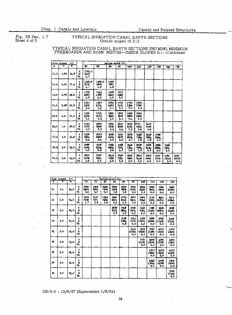
Chap. 1 Canals and Laterals Canals and Related Structures --*
Fig. 3B Par. 1.7 Sheet 4 of 5
TYPICAL LRRIGATION CANAL EARTH SECTIONS (Inside slopes of 2: 1)
TYPICAL IRRIGATION CANAL EARTH SECTIONS SHOWlNG MINIMUM FREEBOARDS AND BANK WIDTHS--INSIDE SLOPES 2:1--Continued
i F; Ub3 1508 1573
13.0 2.95 18.6 % .
1587 1652 1722 1lt.O 2.96 19.8 t
w 'g
.
: 22L2 2337 2432 *nn
19.0 3.0 zl&.o 6726 lOl1 m 5.6 5.7
7.z .
7% a
2986 3168
82 . 95oL 6.0
3197 3302 3572
9r; 10;"; . 10716 6.0
1 t.1 70 YT width f I I I i 75 [ 65 90 95 loo 110 110 130
2soo So0 2700 @oo 900 3200 20
i 3.0
1 7s 7800 8100 8&O
'l&o 9000 9600 lOXI0
.- - . 5.6 5.9 5.9 6.0 6.0 6.0
5 3U2 3552 3792 u-72
3.0 10300 1064x ll38u lZm0 I@32 12820 m 6.0 6.0 6.0 6.0 6.0
. 2s
al- 3.0 24.0 0 ll25o :
Fb 6.0
26
I
3.0 2l4.0 : F-0 I 1;
I I 6.0 6.0 6.0
28 3.0 I &6u 4920 52oe
136y . 1";: . 15620 6.0
P 3.0 aho i liroo
m I 17E
3243 3356 3588 3616 w lcm70 12119 9;:
. 6.0 'Tao
. 11g
. 6.0
h
.
DS-3-5 - 12/8/67 (Supersedes l/6/61)
24
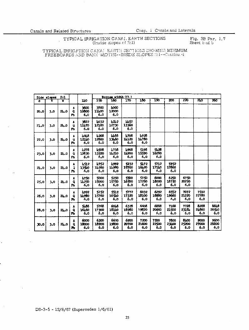
Canals and Reiated Structures Clm~). 1 Cinals arid L9ternls
TYPICAL IRRIGATION CANAi. EP.RTH SECTIONS Fig. 3E Par. 1.7 (Iri:r;icie siopes cf 2: 1) Sheet !> of !b
TYPICAL IRRIGP.‘i‘ICT: C.&>!AI Ei-ii7T:i SE\‘1 l<jY;S WO’hrIN;; MI:‘JlMUM FilEEBCP.RiX AxD &0.X :V~lL1’:-jIS--IT,!S~~~ %OPES :!: 1 --Cxtim d
Botta width (ft ) 150 1 160 1 170 1 180 1 190 i 200 1 220 1 2I40 1 26O
L I
3800 Loa0 lltAo0 12006 .6.0 6.0
\
3322 b032 llll7O 12la,
6.0 6.0
iAm2
l22 .
us2 1336O
6.0
lb708 llbl2O
6.0
l&l48 h268 12lllO 128OO
6.0 6.0
I~278 128P
6.0 23.0 3.0
5232
'Ti .
A %72
53 .
575O 1722
.
5952 1786O
6.0
1:7z 6.0
lr752
ti6T . 2h.O
52sO 15;2
.
do0 1% . 6292
Y? .
25.0 3.0 211.0
2ll.o i lg n .
A 948
4%
2h.O Q 9: n .
' 2ls.o t l&Q0 n 6.0
5252
% .
5512 5772 do32 169~0 17320 18100
6.0 6.0 6.0
5768 Y? .
MO8 19820
6.0 222 2$
6.0 6.0
7728 2318h
6.0
88ld
% .
6Ob8
la% .
1% 6.0
6328
18E .
6900 zom
6.0 1iz
. 2z
6.0
7sDo 22500
6.0 27g 28g
6.0 6.0
9600 288O0
6.0
DS-3-5 - 12/g/67 (Supersedes l/6/61)
25
Chap.
1 C
anals and
Laterals C
anals and
Related
Structures
Fig. 4 Par.
1.10 BAN
K H
EIGH
T FO
R
CAN
ALS AN
D
FREEBO
ARD
FO
R
-
HAR
D
SUR
FACE,
BUR
IED
MEM
BRAN
E, AN
D
EARTH
LIm
GS
i iP;i / - i ! i i i i i
i i i’\i i i i ij
DS-3-5
- 12/8/67
(Supersedes l/6/61)
26
.
w
CANAL CAPACITY - CU. FT. PER. SEC.
IEV. 6-Z-67 103-D-706
Chap. 1 Canals and Laterals Canals and Related Structures
Fig. 8 Par. 1.15A FLAP VALVE WEEPS _
: . ...,: ‘,.; :. i:.<
TYPICAL INSTILL L ATION
SECTION A-A
GRADATION OF FILTER MATERIALS
FLAP VALVE PCI.,‘ or CAR,9
DS-3-5 - 12/8/67
32
Canals and Related Stx.%xv~~ Ciini:. 1 C:?mls and Laterals
.
Fig. 9 Par. :. 15A
k”Mild steel rod, encased in 2” tube of go- lo soft tempered cupro -nickel with 0.049 inch wall thickness.- -. . .,
NOTES Ladder rungs to be placed during concti
lining operations, located opposite each other of 750 ft. intervals on each side of tht canal, and upstream of structures OS dimtet
Ladder rungs are not required on sides of canals where the vertical lining height is less than 2i feet.
LADDER RUNG STANDARD DESIGNS
DS-3-5 - 12/8/U
33
Chap. 1 Canals and Laterals Canals and Related Structures
Fig. 10 Par. 1.15A S 9FETY LADDER FOR CONCRETE-LINED CANALS
use tm or mom bdde sactlons when . . . - . . . . ..A I..... . . . . . J. Porn* omo d, don concmte .,t* two coals of tmfffc ydbv parat.
INSTALLATION DETAIL
LADDER SECT/ON
Ardors not shown SECTION A-A L.ooER a”“6 061.11
NOTES Lo6dars to be vsoa 0” sfdos of cowl hwa tbo vortrcol
lrnrnp hcqht is 2 ’ foot or mom. Lodh-s to bo bcat~ onposIt* wcn other at ?soaotmbndsmn
*dr~ord*~dsosAm~ LoOdors to bo lbbncotd fron steel OT 606~ 16 olunincn. LoMars shollbs mhorrd to the conot linrnp rrtb 6toinless
stool owonsrm t * the o#wwol o c
w or tqoct tym onchws. subjut fhe mtmctinp officer.
LoWcrs to be noded with mm-cwrosive trofflc yetlow oomt after tibricotien.
l=T- __.-..- ._.. - ._._ - - .._ -
C”.#uIO IOR Coocm~S ‘oc.I,O”
- .
DS-3-5 - 12/a/67
34
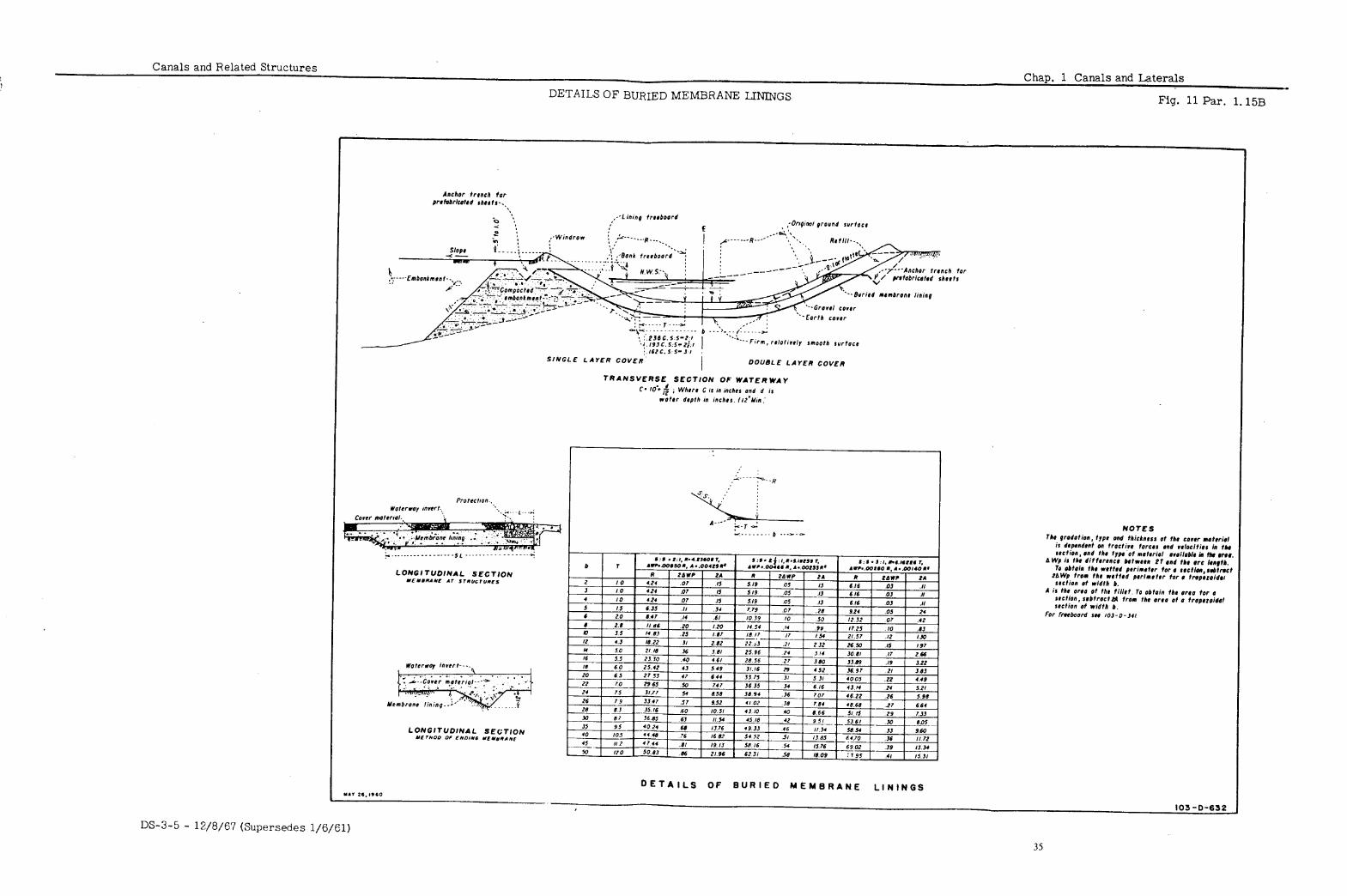
Canals and Related Structures Chap. 1 Canals and Laterals
TYPICAL EARTH-LINED SECTIONS Fig. 12 Par. 1.1X
in fill I I 111 cut --
k- ------ &9lrnf prowId surfoct
oallkfroeboord~ .
\C,m,wctrd
TYPICAL EARTH LlivED SECTION
d link9 ebs lho ororcl w riPm9 cowr. ml- frwboord. so0 oq 103-o-34 Inod-IO-CO1
OFT. IC. 0‘7 103-D-104:
DS-3-5 - 12/8/67 37
Canals and Related Structures Chap. 1 Canals and Laterals
CONCRETE OR CLAY DRAIN TILE--DISCHARGE CURVES Fig. 14 Par. 1.24
SLOPE 1N lNC”ES PER 100 FEET
SLOPE IN FEET PER 100 FEET RATE OF RUNOFF PER ACRE
PER 24 “OURS
DISCHARGE CURVES FOR DRAIN-TILE
BASED ON FORMULA V= 138 R2/, S4 B”L.IS.. KS. DCIT. OF .O”IC”LI”“L
DS-3-5 - 12/8/67 (Supersedes l/6/61)
41
Canals and Related Structures Chap. 2 General Design Information for Structures
TABLE OF CONTENTS
Paraqraph
E ::i 2; zo 2:11 2.12 2.13 2.14 2.14A 2.14B 2. 15 2.16
. . 2. 17 General 2.18 Dead Loads 2.19 Live Loads 2.20 Vertical Wall Loads 2.21 Sloped Walls 2.22 2.23
Highway and Railroad Loads Loads on Circular Conduits
2.24 2.25 2.25A 2.25B 2.25C 2.25D 2.25E 2.25F 2.26 2.27 2.28 2129
2.30 2.31
GENERAL DESIGN CONSIDERATIONS
Introduction Data
REINFORCED CONCRETE DESIGN CRITERIA
General Allowable Stresses Bar Spacing Splicing of Bars Protective Cover Bond and Anchorage Requirements Shear Requirements Minimum or Temperature Reinforcement Reinforcement Bar Bends Minimum Wall Thickness Cutoff Walls Joints in Structures
Construction Joints Contraction Joints
Fillets Concrete Pipe
LOADINGS
HYDRAU LIC S
Flow Formulas Head Loss
Friction Loss Transitions Bends Trashracks Piers Miscellaneous
Freeboard Percolation Overturning and Sliding Hydraulic Jump
RIPRAP
General Siphons and Tunnels
DS-3-5 - 12/8/67 43
Chap. 2 General Design Information for Structures
Canals and Related Structures
TABLE OF CONTENTS--Continued
RIPRAP--Continued
.
Paraqraph
2.32
2.33 2.34
2.35 General
2.36
Eli 2: 39 2.40
Checks, Parshall Flumes, Check Drops, Inclined Drops, Chutes, and Closed-conduit Drops
Turnouts Cross Drainage Structures
PIPE EARTHWORK
AUTOMATIC AND REMOTE OPERATION OF WATER CONVEYANCE SYSTEMS
General Measuring Stations Gate Controls Supervisory Circuits and Remote Controls Safety Features
APPENDIX A--The Hydraulic Jump
.-
p ..j
DS-3-5 - 12/8/67
44
Canals and Related Structures Chap. 2 General Design Information for Structures
TABLE OF CONTENTS--Continued -
Figure Number
1
2
3
4
20
21
22
23
24
25
26
27
28
29
LIST OF FIGURES
Title Paragraph Reference
Drawing Number
Reinforced Concrete Design- - Combined Bending and Tension
Reinforced Concrete Design-- Combined Bending and Compression
General Notes and Minimum Require- ments for Detailing Reinforcement-- Class 40 and Class 50
General Notes and Minimum Require- ments for Detailing Reinforcement-- Class 60
Protective Covering for Reinforcement Radius of Bend for Beam and Slab
Reinforcement. Earth Pressure and Moment Curves--
Angle of Repose = l-1/2:1 Earth Pressure and Moment Curves--
Angle of Repose = l-3/4:1 Earth Pressure and Moment Curves--
Angle of Repose = 2:l Resulting Pressures--Sloped Walls Distribution of Wheel Loads for Design
of Culverts Design of Free-flow Siphon Inlets Head Losses in Pipe Bends Compound Pipe Bends Head Loss Through Trashracks Flow Through Submerged Tubes Critical Depth in Trapezoidal Sections Energy Loss in Hydraulic Jump Relations Between Variables in
Hydraulic Jump Earthwork Details, Monolithic Con-
crete Pipe--Earth Excavation Earthwork Details, Monolithic Con-
crete Pipe--Unclassified Excavation Earthwork Details, Monolithic Con-
crete Pipe--Earth or Rock Excavation Earthwork Details, Pretensioned Con-
crete Pipe--Earth Excavation Earthwork Details, Pretensioned Con-
crete Pipe--Unclassified Excavation Earthwork Details, Pretensioned Con-
crete Pipe--Earth or Rock Excavation Earthwork Details, Precast Concrete
or Asbestos-Cement Pipe--Earth Excavation
Earthwork Details, Precast Concrete or Asbestos-Cement Pipe-- Unclassified Excavation
Earthwork Details, Precast Concrete or Asbestos-Cement Pipe--Earth or Rock Excavation
Pressure Pipe--Typical Trenches
2.4 103-D-344
2.4 103-D-343
2.6 40-D-7004
I:!
2.11
2.18
2.18
2.18 2.21
2.22 2.25B 2.2x 2.2x 2.25D 2.25F 2.25F 2.29
2.29
2.35
2.35
2.35
2.35
2.35
2.35
40-D-6123 103-D-143
103-D-142
103-D-197
103-D-198
103-D-199 103-D-195
103-D-229 103-D-1 106-D-44 106-D-32 106-D-71 103-D-276 ;g-g-gm;
s -
103-D-306
103-D-1062
103-D-1063
103-D-1064
103-D-1059
103-D-1060
103-D-1061
2.35
2.35
2.35 2.35
103-D-1056
103-D-1057
103-D-1058 40-D-6036
DS-3-5 - 12/8/67
Canals and Related Structures Chap. 2 General Design Information for Structures.
.l
-
.2
.3
.4
2. 1
GENERAL DESIGN CONSIDERATIONS
This chapter contains design information used for many types of canal INTRODUCTION structures. The hydraulic and structural designs ‘are generally based on information found in recognized design textbooks. The loadings and stand- ards given in this chapter are adequate for most conditions; however, engi- neering judgment must be exercised to determine when they do not fit local conditions. In the structural drawings selected for illustration, there may be instances in which current design practices differ in some respects from those illustrated.
Design data are prepared or obtained by field forces. It is their responsi- bility to anticipate the needs of the designers and obtain reliable information on all factors that may influence design. The data should include drawings and other information necessary for the complete design of the structures. The desirable scale for profile drawings is 1 inch equals 10 feet vertical and 1 inch equals 200 feet horizontal, although high density of structures may sometimes warrant a horizontal scale of 1 inch equals 100 feet. Profiles and structures should be oriented on drawings so that the stationing increases from left to right or from bottom to top. For additional information, see Part 133, Design Data Requirements, of the Reclamation Instructions.
DATA
REINFORCED CONCRETE DESIGN CRITERIA
The current AC1 (American Concrete Institute) Building Code requirements and subsequent AC1 standards with exceptions as approved by the Bureau’s Division of Design are used as a guide for canal structures. Design criteria for bridges are covered in Chapter 9, Bridges, of this design standards.
GENERAL
Most designs for canal structures are based on 3,000-psi stren $”
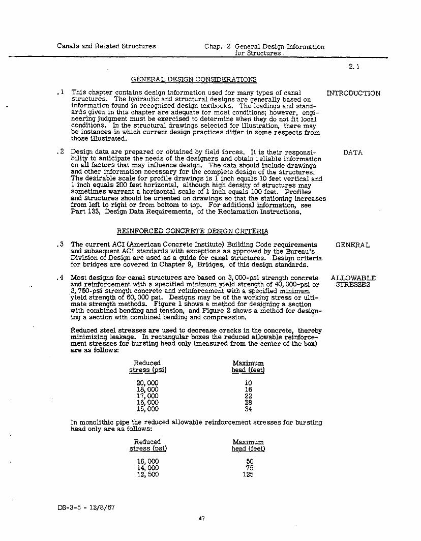
concrete ALLOWABLE and reinforcement with a specified minimum yield strength of 4 , OOO-psi or STRESSES 3,750-psi strength concrete and reinforcement with a specified minimum yield strength of 60,000 psi. Designs may be of the working stress or ulti- mate strength methods. Figure 1 shows a method for designing a section with combined bending and tension, and Figure 2 shows a method for design- ing a section with combined bending and compression.
Reduced steel stresses are used to decrease cracks in the concrete, thereby minimizing leakage. In rectangular boxes the reduced allowable reinforce- ment stresses for bursting head only (measured from the center of the box) are as follows:
Reduced Maximum stress (psi) (feet) head
%% 10
17’ 000 16: 000
8:
15,000 t:
In monolithic pipe the reduced allowable reinforcement stresses for bursting head only are as follows:
Reduced’ Maximum stress (psi) (feet) head
:4:: 50
12: 500 172:
DS-3-5 - 12/8/67 47
Chap. 2 General Design Information Canals and Related Structures
2.5
SPLICING .6 OF BARS
PROTEC- .7 TIVE COVER
BOND AND .8 ANCHORAGE
R%Ef-
SHEAR .9 REQUIRE-‘
MENTS
MINIMUM .10 OR TEM-
PERATURE REINFORCE-
MENT
- --
REINFORCED CONCRETE DESIGN CRITERIA--Continued
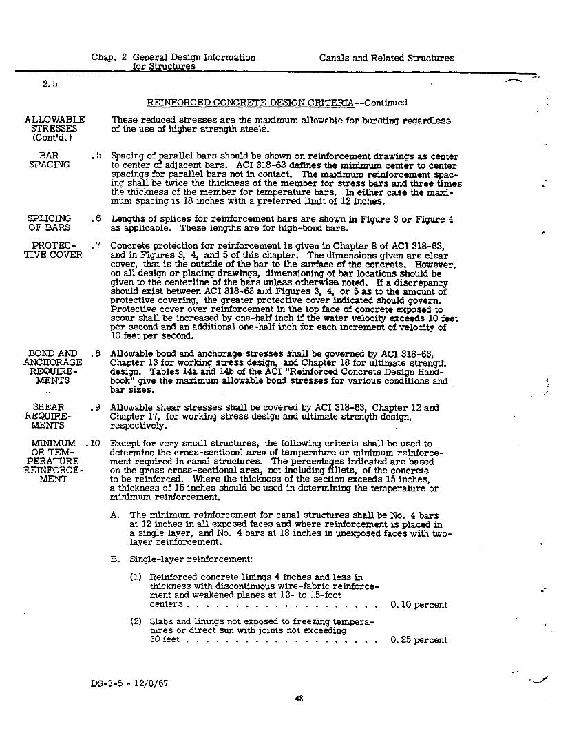
These reduced stresses are the maximum allowable for bursting regardless of the use of higher strength steels.
Spacing of parallel bars should be shown on reinforcement drawings as center to center of adjacent bars. AC1 318-63 defines the minimum center to center spacings for parallel bars not in contact. The maximum reinforcement spac- ing shall be twice the thickness of the member for stress bars and three times the thickness of the member for temperature bars. In either case the maxi- mum spacing is 18 inches with a preferred limit of 12 inches.
Lengths of splices for reinforcement bars are shown in Figure 3 or Figure 4 as applicable. These lengths are for high-bond bars.
Concrete protection for reinforcement is given in Chapter 8 of AC1 318-63, and in Figures 3, 4, and 5 of this chapter. The dimensions given are clear cover, that is the outside of the bar to the surface of the concrete. However, on all design or placing drawings, dimensioning of bar locations should be given to the centerline of the bars unless otherwise noted. If a discrepancy should exist between AC1 318-63 and Figures 3, 4, or 5 as to the amount of protective covering, the greater protective cover indicated should govern. Protective cover over reinforcement in the top face of concrete exposed to scour shall be increased by one-half inch if the water velocity exceeds 10 feet per second and an additional one-half inch for each increment of velocity of 10 feet per second.
Allowable bond and anchorage stresses shall be governed by AC1 318-63, Chapter 13 for working stress desi design. Tables 14a and 14b of the r
and Chapter 18 for ultimate strength
book” give the 61 “Reinforced Concrete Design Hand-
msximum allowable bond stresses for various conditions and bar sizes.
Allowable shear stresses shall be covered by AC1 318-63, Chapter 12 and Chapter 17, for working stress design and ultimate strength design, respectively.
Except for very small structures, the following criteria shall be used to determine the cross-sectional area of temperature or minimum reinforce- ment required in canal structures. The percentages indicated are based on the gross cross-sectional area, not including fillets, of the concrete to be reinforced. Where the thickness of the section exceeds 15 inches, a thickness of 15 inches should be used in determining the temperature or minimum reinforcement.
A. The minimum reinforcement for canal structures shall be No. 4 bars at 12 inches in all exposed faces and where reinforcement is placed in a single layer, and No. 4 bars at 18 inches in unexposed faces with two- layer reinforcement.
B. Single-layer reinforcement:
(11 Reinforced concrete linings 4 inches and less in thickness with discontinuous wire-fabric reinforce- ment and weakened planes at 12- to 15-foot centers . . . . . . . . . . . . . . . . . . . . 0.10 percent
(21 Slabs and linings not exposed to freezing tempera- por;zey direct sun with joints not exceeding
. . . . . . . . . . . . ..a . . . . . 0.25 percent
--
DS-3-5 - 12/8/67 - .
3 f - , :
48
Canals and Related Structures Chap. 2 General Design Information for Structures
.(3)
(4)
(5)
2.1OC
REINFORCED CONCRETE DESIGN CRITERIA--Continued
Slabs and linings exposed to freezing tem- peratures or direct sun with joints not exceeding 30 feet . . . . . . . . . . . . , . . 0.30 percent
Slabs and linings exceeding 30 feet between joints Category (2) above . . . . . . . . . . . . . . 0.35 percent Category (3) above . . . . . . . . . . . . . . 0.40 percent
fitYE%: PERATURE
REINFORCE- MENT
(Cont’d. )
Walls and other structural members Total percentage of horizontal reinforcement to be equal to the sum of those required for both faces as determined below.
C. Double-layer reinforcement:
(1) F’F’;Ee;djacent to earth with joints not exceeding . . . . . . . . . . . . . . . . . . . 0.10 percent
.11
.12
.
(2) Face not adjacent to earth nor exposed to freezing temperatures or direct sun and with joints not exceeding 30 feet . . . . . . . . . . . . . . . 0.15 percent
(3) Face not adjacent to earth but exposed to freezing temperatures or direct sun and with joints not exceeding 30 feet . . . . . . . . . . . . . . . 0.20 percent
(4) If member exceeds 30 feet in any direction parallel to reinforcement, add to the reinforcement require- ment in that direction because of the increased length . . . . . . . . . . . . . . . . . . . . 0.05 percent
(5) If a slab is fixed along any line, double the dimension from line of fixity to free end to determine whether rein- forcement is within the less than 30 feet or more than 30 feet percentages shown under (11, (21, (3), and (4) above.
Minimum pin diameters for bent bars shall conform to the tabulation on the applicable Figure 3 or Figure 4. An adequate radius shall be provided to prevent crushing of the concrete, when bends are made at points of high stress (see Figure 61.
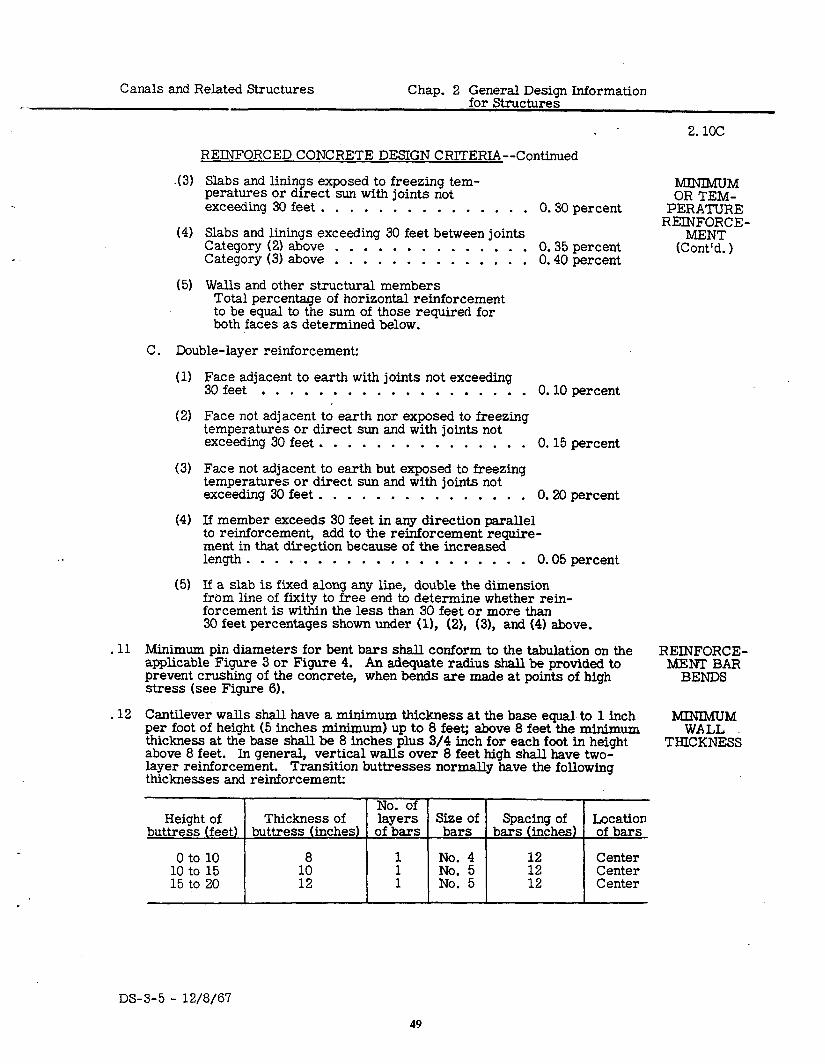
Cantilever walls shall have a minimum thickness at the base equal. to 1 inch per foot of height (5 inches minimum) up to 8 feet; above 8 feet the minimum thickness at the base shall be 8 inches plus 3/4 inch for each foot in height above 8 feet. In general, vertical walls over 8 feet high shall have two- layer reinforcement. Transition buttresses normally have the following thicknesses and reinforcement:
No. of Height of Thickness of layers Size of Location
buttress (feet) buttress (inches) of bars Spacing of
bars bars (inches) of bars
0 to 10 8 10 to 15
:; i
No. 4 12 Center No. 5 12 Center
15 to 20 1 No. 5 12 Center
DS-3-5 - 12/8/6’7
49
2.13
CUTOFF WALLS
JOINTS IN STRUC- TURES
Construction Joints
.
Contraction Joints
FILLETS
Chap. 2 General Design Information for Structures
Canals and Related Structures
.13
REINFORCED CONCRETE DESIGN CRITERIA--Continued
Cutoffs are provided to reduce percolation around structures, to prevent movement of structures, and to make transitions more rigid. Cutoffs are required at the ends of structure transitions in concrete-lined canals as well as in other lined or earth canals. Cutoff walls should, in general, be a mini- mum of 24 inches deep, measured perpendicular to the inside of the struc- ture, for water depths up to 3 feet over the cutoff, 2 feet 6 inches for water depths of 3 to 6 feet, and 3 feet for water depths over 6 feet. For some small structures, 18-inch cutoffs may be satisfactory. The minimum con- crete thickness should be 6 inches for 18- and 24-inch cutoffs, 8 inches for 2-foot 6-inch and 3-foot O-inch cutoffs. In soils that are unusually suscep- tible to piping, the cutoff should be extended horizontally or vertically, or both, to provide adequate protection against percolation. If minimum cutoffs are specified, a-note should be added requiring cutoff extension with unrein- forced concrete as directed. This will permit deeper and wider cutoffs to be used where excavation discloses poor soils without complicating reinforce- ment cutting and bending. The vertical reinforcement in the cutoff is usually the same as the longitudinal reinforcement in the transition floor. If only one layer of reinforcement is used in a cutoff, the vertical reinforcement should be placed in the center of the cutoff wall.
.14 Construction and contraction joints are often used in concrete and canal structures.
A. Construction joints are joints which are purposely placed in structures to facilitate construction or which occur in structures as a result of in- advertent delays in concrete placing operations. Construction joints are located to facilitate the contractor’s operations, to reduce initial shrink- age stresses and cracks, to allow time for the installation of embedded metalwork, or to allow for the subsequent placing of other concrete, backfill concrete, or second-stage concrete. Bond is required at con- struction joints regardless of whether or not reinforcement is continuous across the joint.
B. Contraction joints are joints placed in structures or slabs to provide for volumetric shrinkage of monolithic unit or movement between mono- lithic units. The joints are so constructed that there will be no bond between the concrete surfaces forming the joint. The joints are made by forming the concrete on one side of the joint and allowing it to set before concrete is placed on the other side of the joint. The surface of the concrete first placed at a contraction joint shall be coated with seal- ing compound before the concrete on the other side of the joint is placed. If steel bars or dowels extend across the joint, one end of the bar should be coated or wrapped with paper to prevent bonding to the concrete. A sponge-rubber elastic filler should be provided at the joint if expansion is expected. Rubber waterstops with center bulb should be placed across joints where it is necessary to prevent water from passing through the joint. Plastic waterstops may be used in lieu of rubber waterstops for low-head structures.
. 15 Fillets are often used to provide increased strength or relieve stress concen- trations at points of maximum stress, and to facilitate the placement of con- crete. The sizes of fillets usually provided at the inside corners of box sections and at the bases of vertical cantilever walls are as follows:
DS-3-5 - 12/8/67 50
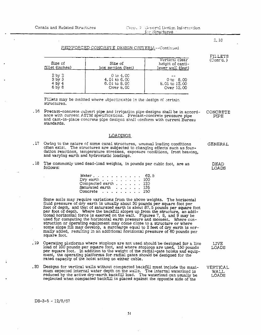
REINFORCED CONCRETE DESIGN CRITERIA--Continued
Size of Size of fillet (inches) box section (feet)
Verticai clear height of canti-
lever wall (feet)
2 by 2 0 to 4.00 3 by 3 4.01 to 6.00 0 ti- 8.00 4 by 4 6.01 to 8.00 8.01 to 12.00 6 by 6 Over 8. OC Over 32.00
Fillets may be omitted where objectionable in the design of ::ertain structures.
. 16 Precast-concrete culvert pipe and irrigation pipe designs shall be in accord- ance with current ASTM specifications. Precast-concrete pressure pipe and cast-in-place concrete pipe designs shall conform with current Bureau standards.
LOADINGS
. 17 Owing to the nature of some canal structures, unusual loading conditions often exist. The structures are subjected to changing effects such as foun- dation reactions, temperature stresses, exposure conditions, frost heaving, and varying earth and hydrostatic loadings.
GENERAL
. 18 The commonly used dead-load weights, in pounds per cubic foot, are as DEAD follows: LOADS
Water . . . . . . . . . . . 62. 5 Dry earth . . . . . . . . . 100 Compacted earth . . . . . . 120 Saturated earth . . . . . . 135 Concrete . . . . . . . . . 150
Some soils may require variations from the above weights. The horizontal fluid pressure of dry earth is usually about 30 pounds per square foot per foot of depth, and that of saturated earth is about 87.5 pounds per square foot per foot of depth. Where the backfill slopes up from the structure, an addi- tional horizontal force is exerted on the wall. Figures 7, 8, and 9 may be used for computing the horizontal earth pressure and moment. Where con- struction or operating equipment may come close to a structure or where some slope fill may develop, a surcharge equal to 2 feet of dry earth is nor- mally added, resulting in an additional horizontal pressure of 60 pounds per square foot.
19 . Operating platforms where stoplogs are not used should be designed for a live load of 100 pounds per square foot, and where stopiogs are used, 150 pounds per square foot. In addition to the weight of the radial-gate hoists and equip- ment, the operating platforms for radial gates should be designed for the rated capacity of the hoist acting on either cable.
IJVE LOADS
.20 Designs for vertical walls without compacted bacidill must include the maxi- mum expected internal water depth on the walls. The internal waterload is reduced by the active dry-earth backfill load. The waterload can usually be neglected when compacted backfill is placed against the opposite side of the
VERTICAL WALL LOADS
2. 16
FILLETS (Cont’d. )
CONCRETE PIPE
DS-3-5 - 12/8/67
Chap. 2 General Design Information Canals and Related Structures
2. 21
VERTICAL WALL LOADS
(Cont’d. )
SLOPED WALLS
mG&Yy RAILROAD
LOADS
LOADS
CH?::LAR CONDUITS
FLOW FORMULAS
. .
HEAD Loss
Friction Loss
Transitions
-21
-22
.23
.24
-25
LOADINGS--Continued
wall. If the wall is not backfilled, the design should be based on internal water to the-top of the wall, plus ice pressure where it may occur, and nor- mal stresses used to resist the resultant moment. The backfill load must be considered regardless of compaction. If the backfill can become saturated, the additional load must be used for design.
Sloped walls are usually designed to be supported by the foundation upon which it is placed. See Figure 10 for resulting pressures on sloped walls. But- tress walls are often used for large transitions and the maximum loads from both sides of the wall must be considered when determining how the walls will be supported.
Figure 11 shows loadings and distribution of loads commonly used for high- way and railroad structures. Some State highway commissions and railroad companies have special requirements and standards which must be followed for structures on their right-of-way.
Bureau of Reclamation Engineering Monograph No. 6, %.ress Analysis of Concrete Pipe, ” by H. C. Olander, describes the loadings and a method of analysis for designing buried circular conduits. Also, ultimate load analysis is being used as a method of designing precast and monolithic siphon barrels.
HYDRAULICS
The Manning formula (Paragraph 1.12) is generally used for designing canals and related structures except in precast concrete pipe distribution systems. Scobey’s formula is generally used for precast concrete pipe distribution system designs with the recommended value of Ce given in the Bureau’s Hydraulic and Excavation Tables. These tables also include tabular solutions for Manning’s formula and many other tables which are useful in designing canals and structures.
The more common head losses are due to friction, transitions, bends, trash- racks, and changes in cross-sectional area. The roughness coefficients for unlined and lined canals are given in Chapter 1.
A. In open channel systems a roughness coefficient 9irr. of 0.014 is used for all monolithic-concrete structures except conduits. If constructed with steel forms, monolithic-concrete pipe and tunnels use a roughness co- efficient of 0.013. A roughness coefficient of 0.013 is also used for precast concrete pipe. For closed distribution systems carrying clear water, Scobey’s formula is used. A coefficient of retardation, C,, of 0.345 is used for pipe diameters 22 inches and smaller and a Cs of 0.370 for pipe sizes 24 inches and greater.
B. Transitions are generally used at the inlet and outlet of structures and where changes occur in the water section. An accelerating water veloc- ity usually occurs in inlet transitions and a decelerating velocity in out- let transitions. The most common types of open transitions to closed conduits are the streamlined warp, straight warp, and broken back. (“Broken back” refers to the intersection of the vertical and sloping plane surfaces on the sides of the transition; the type is also sometimes re- ferred to as “Dog leg”. 1
Inlet tr?csitions for minimum hydraulic loss and smooth operation should have a submergence or seal of 1.5 (hvp - hvc) or 3 inches minimum measurf?d between the upstream water surface of the inlet transition and the opening in the transition headwall. Outlet transitions should have no
.
2 ,
--’
_-
DS-3-5 - 12/8/67 52
Canals and Related Structures Chap. 2 General Design Information for Structures
2.2x
HYDRAULICS--Continued
submergence of the opening in the headwall. If the submergence exceeds Transitions one-sixth of the depth of the opening at the outlet, the hydraulic loss should be computed on the basis of a sudden enlargement rather than as
(Cont’d. 1
an outlet transition. The hydraulic loss in a transition will depend pri- marily on the difference between the velocity heads at the open end of the transition and at the normal to centerline section of the closed con- duit at the headwall, or A hv. Coefficients of Ahv considered adequate for determining hydraulic losses in transitions are tabulated below.
Tvoe of ooen transition to closed conduit Inlet Outlet --
Streamlined warp to rectangular opening . . . . 0.1 Straight warp to rectangular opening. . . . . . 0.2 2: Straight warp with bottom corner fillets
to pipe opening. . . . . . . . . . . . . . . 0.3 Broken back to rectangular opening . . . . . . 0.3 El Broken back to pipe opening . . . . . . . . . 0.4 0: 7
Closed transition
Square or rectangular to round (maximum angle with centerline = 7-l/2”) . . . . . . . 0.1 2
Open transitions to multiple closed conduits will involve some additional hydraulic loss. Average friction loss should be adued for large transi- tions, but it may be neglected for small transitions. The slope of the floor on a broken-back outlet transition should be 6~1 or flatter.
The maximum angle between the water surface and the centerline should not exceed 27-l/2” for inlet transitions and 22-l/2” for outlet transitions for the best hydraulic conditions. In some structure designs it may prove economical to use 25” to allow the same structure to be used for both inlets and outlets. A 30” angle is often used on inlet transitions with checks, in which case an additional loss is allowed for the check. Designs should provide for a loss through most check structures of about 0.5 times the difference in velocity head through the check opening and the upstream canal section.
Where an inlet transition connects to a free-flow closed conduit in such a way that the conduit inlet is sealed, the quantity of water that is passed should be determined by the orifice equation. The head should be meas- ured from the center of the opening to the inlet water surface and an ori- fice coefficient of c = 0.6 should be used. A small correction factor is theoretically required when the submergence is less than the height of the opening. When the inlet to a long conduit may operate without seal- ing, a hydraulic jump may occur that can result in blowback and undesir- able operation. Figure 12 can be used to determine the probability of blowbacks existing in any particular structure. Transitions to free-flow conduits can have the control point anywhere between the inlet cutoff and the headwall. If control at any flow is at the inlet cutoff, the upstream channel must be protected from erosion or the design changed to move the point of control to the transition.
C. The head loss in feet for bends in closed conduit may be computed from Rends the formula,
DS-3-5 - 12/8/67 53
Chap. 2 General Design Information for Structures
Canals and Related Structures
2.25D
HYDRAULICS- -Continued
Bends (Cont’d. ) hb= Z(& 1’2g
>
where
Z = a coefficient based on radius of pipe bend and diameter of pipe, and
Trashracks
A = deflection angle of pipe bend.
5 may be obtained from Figure 13. Hinds head loss based on 2 = 0.25 is also shown and, although conservative, it may be adequate for pre- liminary estimates. pipe bends.
Figure 14 shows methods for computing compound
D. Trashrack losses may be estimated as follows:
Velocitv throuah rack (fos) Loss in feet
:*z 0.10
2:o 0.30 0.50
More accurate losses may be obtained from Figure 15.
Piers E. The cumulative backwater effect of structure piers in the canal prism .- shall be considered in the design of canals on very flat grades.
Miscellaneous F. Coefficients for use in the orifice formula for flow through submerged tubes may be obtained from Figure 16. Figure 1’7 provides a quick method of determining approximate critical depth in trapezoidal sections.
FREE- BOARD
.26 The freeboard for the end of transitions adjacent to hard-surface or buried- membrane canal lining is usually the same as that of the lining. In unlined and earth-lined canals, the minimum freeboard at transition cutoffs for siphons, tunnels, and similar structures should be as follows:
Water depth Minimum at cutoff (feet) freeboard (inches1
0 to 1.25 1.26 to 2.00 2.01 to 5.00 5.01 to 7.00 7.01 to 9.00 9.01 to 12.00
For small structures such as transitions connecting to 24-inch-diameter pipe and smaller, the top of the transition walls may be level. For larger struc- tures, the freeboard at the transition headwall should be greater than at the cutoff; this difference in freeboard will increase as the size of the structure increases.
Chapter 1 gives the recommended freeboard for canals. The earth bank free- board should be increased 50 percent (1.0 foot maximum) adjacent to siphons, wasteways, and checks without overflows, to prevent washouts at these loca- tions due to more floodwater being taken into the canal than allowed for in
--
DS-3-5 - 12/8/67 54
Canals and Related Structures Chap. 2 General Design Information for Structures
2. 27
HYDRAULICS--Continued
designs or by improper operation. The increased freeboard is to be zx- tended away from the structure to a point where the least damage due to overtopping will occur, or a minimum distance of 50 feet.
FREEBOARD (Cont’d. 1
.27 Where water is confined in an area above a point of relief, such as above PERCOLATION a check structure, there is a tendency for the water to flow along the struc- ture or through the earth to the lower point of relief. The type of structure and the nature of the soil will govern the amount and rate of the flow. The percolation factor should be at least 2.5:1 as computed by Lane’s weighted creep method, and 3.5:1 on a straight path. Straight path factors of 5:l are common. Larger factors may be required where warranted by the type of soil or importance and type of structure.
The percolation path may be increased by adding length or cutoff walls to most structures. Cutoff walls must be far enough apart to prevent a short circuit between the ends of the cutoffs. The cutoffs must be so spaced that the actual distance between the cutoffs will be at least one-half the weighted creep distance along the structure between the ends of the cutoffs. For com- puting weighted cidep distance, the hcrizontal distance is considered to be one-third as effective as the vertical distance.
.28 All structures must be checked for stability. Especially, small check struc- OVER- tures often require additional length to prevent overturning or sliding for TURNING maximum upstream and minimum downstream water surface. The sliding AND factor, defined as the ratio of the horizontal forces to the total weight re- SLIDING duced by uplift, should not exceed 0.35 for most conditions. Cutoff walls may be added to increase the sliding resistance.
. .29 A treatment of hydraulic jump and critical depth and their application to HYDRAULIC
design is given in Appendix A to this chapter, which is a reprint of an article JUMP by Julian Hinds entitled “The Hydraulic Jump and Critical Depth in the Design
.of Hydraulic Structures. ” See also Figures 17, 18, and 19.
RLPRAP
.30 Riprap protection is often used adjacent to structures and at other locations GENERAL in earth-surfaced canals where erosion may occur. The local conditions must be considered in determining the type and amount of protection to be provided. These conditions include the cost of riprap, cost of gravel, danger to structures and crops or to human life should scour occur, rodent protec- tion, type of soil, and velocity of water. In areas where riprap and gravel are scarce, consideration should also be given to stockpiling riprap under the construction contract for later use by operation and maintenance forces. The following protection requirements are to be used as a guide only. Types of protection are identified herein for convenience in discussing the protection requirements. The types shown represent minimum sizes and amounts of material to be used, and adjustments should be made to meet the local condi- tions mentioned above.
Type l--6-inch coarse gravel Type 2--12-inch coarse gravel Type 3--12-inch riprap and g-inch sand and gravel bedding Type 4--18-inch riprap and 6-inch sand and gravel bedding
Except for cross-drainage structures, Type 3 minimum protection should be used where velocities exceed 5 feet per second, regardless of depth.
DS-3-5 - 12/8/67 55
2.31
Chap. 2 General Design Information for Structures
Canals and Related Structures --_
r‘- ,^
RIPRAP- -Continued :.. ‘..:: _I ._ ,.>...”
SIPHONS . 31 AND
The following protection is considered minimum for siphons and tunnels in earth-surfaced canals:
TUNNELS d = water depth adjacent
to structure (feet) Inlet Cutlet
0 to 2.00 None None 2.01 to 3.50 None 3.51
Type1 to 7.00 Type 1
7.01 Type 2
to 10.00 Type 2 5Pe 3
L .
PARSHALL FLUMES, CHECKS,
CHECK DROPS,
INCLINED DROPS,
CHUTES, AND
CLCSED- CONDUIT
DROPS
Water depths over 10 feet require special consideration.
Protection called for on inlets may be omitted if the velocity is less than 2.5 feet per second.
Where protection is required on inlets, length = d (3.0 feet minimum).
Where protection is required on outlets, length = 2.5d (5.0 feet minimum).
.32 The following protection is considered minimum for Parsball flumes, checks, check drops, inclined drops, chutes, and closed-conduit drops with control section on concrete, that is, where critical depth does not occur off the con- crete. Where critical depth may occur off the concrete, the next higher type of protection should be used at the inlet.
d = water depth adjacent to structure (feet) Inlet Cutlet
I 0 to 2.00 None
2.01 to 3.50 None 3.51 to 7.00 Type 1 7.01 to 10.00 Type 2
Water depths over 10 feet require special consideration.
Protection called for on inlets may be omitted if velocity is less than 2.5 feet per second.
Where protection is required on inlets, length = d (3.0 feet minimum).
Length of protection on outlets = 2.5d (5.0 feet minimum).
Where turbulent water may occur at the outlet, the length of protection should be increased to 4d.
Gates or stoplogs near the outlet increase turbulence.
TURNOUTS .33 Protection is not required on the inlets to most small turnouts. If the turnout capacity is 5i! oxcent or more of the capacity of the canal, the protection recommended ion siphon inlets should be used. Protection at the outlets of turnouts should. brl the same as for siphons, based on the water depth in the lateral adjacerzt :r? the outlet transition.
< :. . ./
.
DS-3-5 - 12/B/67 56
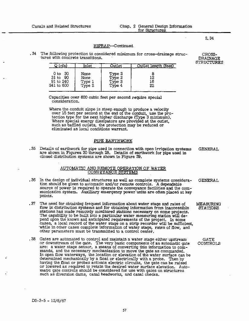
- Canals and Related Structures Chap. 2 General Design Information
for Structures
.34
.35
.36
.37
.38
RIPRAP- -Continued
The following protection is considered minimum for cross-drainage struc- tures with concrete transitions.
~~
Capacities over 600 cubic feet per second require special consideration.
Where the conduit slope is steep enough to produce a velocity over 15 feet per second at the end of the conduit, use the pro- tection type for the next higher discharge (Type 3 minimum). Where special energy dissipators are provided at the outlet, such as baffled outlets, the protection may be reduced or eliminated as local conditions warrant.
PIPE EARTHWORK
Details of earthwork for pipe used in connection with open irrigation systems are shown in Figures 20 through 28. Details of earthwork for pipe used in closed distribution systems are shown in Figure 29.
AUTOMATIC AND REMOTE OPERATION OF WATER CONVEYANCE SYSTEMS
In the design of individual structures as well as complete systems considera- tion should be given to automatic and/or remote controls. A dependable source of power is required to operate the conveyance facilities and the com- munication system. points.
Auxiliary emergency power units are often placed at key
The need for obtaining frequent information about water stage and rates of flow in distribution systems and for obtaining information from inaccessible stations has made remotely monitored stations necessary on some projects. The capability to be built into a particular water measuring station will de- pend upon the known and anticipated requirements of the project. In some cases, a local record of the water stage on a strip recorder will be sufficient, .while in other cases complete information of water stage, rates of flow, and other parameters must be transmitted to a control center.
Gates are automated to control and maintain a water stage either upstream or downstream of the gate. The very basic components of an automatic gate are: a water stage sensor, a means of converting this information to com- mands, and the necessary mechanisation to move the gate as commanded. In open flow waterways, the location or elevation of the water surface can be determined mechanically by a float or electrically with a probe. Then by having the float or probes activate electric circuits, the gate can be raised or lowered as required to retain the desired water surface elevation. Auto- matic gate controls should be considered for use with gates on structures such as diversion dams, canal headworks, and canal checks.
2.34
CROSS- DRAINAGE
STRUCTURES
GENERAL
GENERAL
MEASURING STATIONS
GATE CONTROLS
DS-3-5 - 12/8/67
57
2.39
Chap. 2 General Design Information for Structures
Canals and Related Structures . .
AUTOMATIC AND REMOTE OPERATION OF WATER CONVEYANCE SYSTEMS--Continued
SUPER - VISORY
C%FTS REMOTE
CONTROLS
SAFETY FEATURES
.39 Data such as reservoir elevation, pipeline pressures, canal flow depths, and gate and valve positions may be transmitted to a control center by means of - supervisory circuits. Gates and valves may be opened, closed, or adjusted, and pumps started or stopped by means of remote control. It is possible with adequate supervisory circuits and remote controls to operate a distribu- tion system from a control center. The mode of communication is either . radio or wire. l
.40 Automatic closure of gates or stopping of pumps may be incorporated in a system to provide for protection of the canal against excessive flows. Alarms at a central control are sometimes incorporated with the supervisory circuits to warn of impending dangers to the system.
DS-3-5 - 12/8/67 58
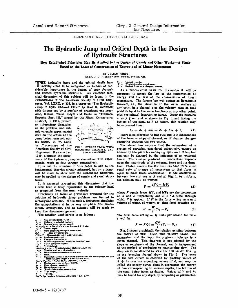
Canals and Related Structures Chap. 2 Generai Design Information for Structures.
APPENDIX A--THE HYDRAULIC JUMP
The Hydraulic Jump and Critical Depth in the Design of Hydraulic Structures
How Established Principles May Be Applied lo the Design of Canals and Other Works-A Study Based on the Laws of Conservation of Energy and of Linear Momentum
BY JULIAN HINDS
. .
HE T hydraulic jump and the critical depth have recently come to be recognized as factors of con-
siderable importance in the design of open channels and related hydraulic structures. An excellent tech- nical discussion of this su.bject will ba found in the Transaction of the American Society of Civil Engi- neers, Vol. LXXX, p. 333. in a paper on “The Hydraulic Jump in Open Channel Flow,” by Karl R. Kennison. with discussions by a number of prominent engineers. Also, Messrs. Ward, Riegel and Beebe in “Technical Reports, Part III.” issued by the Miami Conservancy District, in 1917, present an interesting discussion r L ,
of the problem, and sub- ~Lh,“. 5,
mit valuable experimental & ‘- ” .. , “,.,,,, L--,“, ; ‘:b:ur
data on the action of the ’ :. -- - - .--.. “c _,. : *;
jump below reservoir out- . ..“l”“““” 1:: A.‘,:..-. %I 4
let works. E. W. Lane, ; ~,p”-“-&-z~ -75
. “a in Proceedings of the - American Society of Civil FIG. 1. STEADY FLOW WITH
CIIANCINC VELOCITY. UNI- Engineers, D e c e m b er, FORM CHANNEL 1919, discusses the occur- sence of the hydraulic jump in connection with exper- omental work on flow through contractions.
It is not the intention of this paper to add to the fundamental theories already advanced, but an attempt *ill be made to show how the established principles may be applied to the design of canals and canal struc- turea.
It is assumed throughout this discussion that the kinetic head is truly represented by the velocity head as computed from the mean velocity.
Practically all formulas previously proposed for the solution of hydraulic jump problems are limited to rectangular sections. While such a limitation simplifies the computations it in no way simplifies the funda- mental conceptions, and an attempt will be made to keep the discussion general.
The notation used herein is as follows:
I’, - criticd vclociiY. H’ m We~htol*cubieunadr~. x L Ratioof Ttod lora lria~lurhanncl.
As a fundamental basis for discussion it will be necessary to accept the law of the conservation of energy and the law of the conservation of linear momentum The former law will appear as Bernoulli’s theorem, i.e.. the elevation of the water surface at any point in a channel plus the velocity head at that point is equal to the same functions at any other point, plus (or minus) intervening losses. Using the notation already given and as .shown in Fig. 1 and taking the bottom of the canal at B as datum, this relation may bs expressed thus:
h, + & $ ha. = dr + hb + h/ (1) There is no exception to this rule and it is independent
of the form or slops of channel, or of channel changes occurring between the two points.
The second law requires that the momentum ox a system of particles, considered collectively, cannot bc altered by the particles impinging upon each other, but can only b changed by the influence of an external force. The change produced in momentum depends upon the magnitude of the external force and its dura- tion. Stated simply, the law requires that force must equal rate of change of momentum or that force is equal to mass times acceleration. If the acceleration between two stations as A and LI, Fig. 1, be uniform, the relation may be written
where F equals force, MV. and MVb are the momentum at A and B respectively and t is +‘.e time through which F is applied. If F’ is the force acting on a unit volume of water, of weight W, then from equation (2)
F’ = ; (v, - v., The total force acting on Q units per second for time t will be
F QW = Fqt = b”. (Vb - V.)
Fig. 2 shows graphically the relation existing between the energy of flaw (depth plus velocity head), the momentum and the depth for a given discharge in a given channel. This diagram is not affected by the slope or roughness of the channel, and is independent of the method of producing or maintaining flow. The diagram is constructed to scale for 150 sec.-ft. flowing in the irregular channel shown in Fig. 3. The lower of the two curves is obtained by platting values of d + hv over corresponding values of d. and may be called the energy curve, since it represents the energy of flow corresponding to various depths, the bottom of the cans; being taken as datum. Values of V and hv may be found for any depth by computing or planimeter-
DS-3-5 - 12/8/67 59
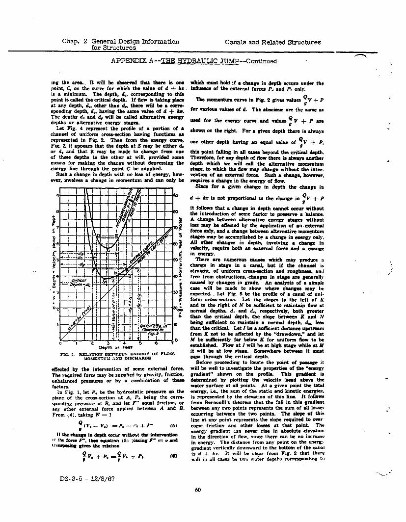
Chap. 2 General Design Information for Structures
Canals and Related Structures
APPENDIX A--THE HYDRAILK! JUMP--Continued
. .
ing the area.. It will be observed that there k OIB point, C, on the curve for which the value of d + hw is a minimum The depth, 6, corresponding to thin point is cal!ed the critica! depth. If flow in taking place at any depth, &., other t!um 4, there wi!! be a allb sponding depth, d,. !uving the same value of d + kv. The deptha d. and 4 will be called a!temative energy depths or alternative energy stagea
Let Fig. 4 represent the profile of a portion of a chorine! of uniform cross-section having function8 aa represented in Fig. 2. Then from the energy curve, Fig. 2, it appears that the depth at S may k either & or 4 and &at it may be made to change from one of these depths to Ule other at will, provided some means for making t!te cbnge without depressing the energy line through the point C be supplied.
Suclt a change in depth with no loss of energy, how- ever, involves a change in momentum and can on!y be
. -
FIG. 2. RlZ,.bTlOW BERVEES ESERGY OF FLOW. JIOUEWTL’U ASD DISCHARGE
e&ted b the intervention of some extema! force. The required force may be supp!ied hy gravity, friction. unbdmced pressures or by a combination of these factors.
In Fig. 1, let P. be the hydrostatic pressure on the p!ane of the cross-section at A. Pb being the corm- rponding pressure at B. and let F” equal friction, or any other external force applied between A and B. From (4). taking W = 1
Q e (VI - V.) = p. -- 1’1 + F” (51
if the dtaege in depth occur r;tho~t the intervention 4 the f0fte F. tlwn cyuatirn (5) $eciag P = e am! ‘-maieg givea the mlattca
0 TV. + P* =p, t Pb
which muat hold if a c!unge in depth occur under the Muem% of the externa! force8 P. and Pb only.
Tbt momentum curve in Fig. 2 given values yv + P
iOr varhms values of d. The a!sscism are the same m
mm! for the energy curve and va!ues % V + P am
shown on the right. For a given dept!r there is a!waya
one other deptla !wing an equal va!ue of zv + p.
thl~ point falling in el! cases wand the critical depth. ThucfOm, for any deptl~ of flow tlmre is days another depth which we will ca!! the a!temative mementum 8We, to which the flow may c!mnge without the inter- vention of an extema! force. Su& a &age, however, rwluireo a change in the energy of flow.
Siam for a given c!mnge in depth the change in
d + kv ia not proportiona! te the c!unge in p+p
it followa that a charge in depth cannat occur without the introduction of nome factor to preeem a balnnce. A change between alternative energy etagea without lo68 may k eRected by the application of an external force only, and a c!mnge between alternative momentum &WCS IIUY k accomplished by a c!mnge in energy only. AU other c!mnges in depth, involving a c!mnge in velocity, require both an extema! force and a c!mnge in energy.
There are numerous caueea which may produce a change in stage in a cana!. but if t!te channel is straight. of uniform crom-aection and mughneaa. an:! free from o!xitructiona,.changea in stage are generally caused by changes in grade. An ana!ynis of a rimple caee will be made to show where changes may IW expected. Let Fig. 5 be the profile of a canal of uni- form cross-section. Let the slopea to the left of li and to the right of N bc ruflicient to meintain f!ow at norma! depths, dc and d.. respective!y, bath greater t!mn the critical depth, the slope ktween K and N being &Rcient to maintain a normal depth, d,. !eaa &an the critica!. Let I be a sufhcient distance upstream from K not to k affected by the “drawdown,” and let M be suiIkient!y far below K for uniform flow to be established. Flow at I will he at high atage while at M it will be at low stage. Somewhere between it must pesa through the critical depth.
Before proceeding to locate the point of passage it will be we!! to investigate the proper&a of the “energy gradient” shown on the profile. This gradient i# determined by plotting the velocity head abeve the water surface at a!! points. At a given mint the total energy, i.e., the sum of the .static and kinetic energies. is represented by the elevation of this line. It fo!!ows from Bernoulli’s theorem that the fall in Otis gradient batween any twm points represents the sum of a!1 IOX* occurring &tween the two points. Tlte slop of this line at any point represents the slope required to over come friction and other losses at that point Thv energy gradient can never rise in absolute elevatior: in the direction of flow. since there can k no incrc?Y.se in energy. The distance from any point on the enertri. gdient vertically downward to the bottom of the CUM is d + hr. It will be c!e.ar from Fig. 2 that there will in aI! cass be two water depths corresponding t’>
.
l
DS-3-5 - 12/8/67 ,
.-__ c .’
60
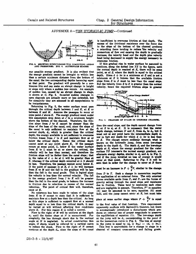
Canals and Related Structures Chap. 2 General Design Information for Structures
APPENDIX A--THE HYDRAULIC JUMP--Continued
FIO. 1. SNOWING SIBDIVISIONS FOR COMPUTING AREAS AND PRESSURES FIG. 4. ALTERNA~ STAGES
any possible energy gradient. It is also evident that the energy gradient cannot be brought to within less than a certain minimum distance from the bottom of the canal, the two corresponding depths becoming equal at that point. The gradient will generally be a con- tinuous line and can make an abrupt change in height or slope only where a sudden loss occurs. An example of sudden loss, caused by an abrupt change in atage, is shown at 0, Fig. 5. Soulled sudden changes in open channels are actually more or less extended, but for rimplicity they are assumed in all computations to be instantaneous.
Returning to Fii. 5. the water surface must paas through the critical deptb between I and K, at K or bttwttn K and M. Assume the pawages to occur at some point J above K. The energy gradient must under this assumption drop down at I to a minimum height above tbt bottom of the channel. Tberefore. the fric- tion alope from J to K cannot be steeper than the tlope of the btte of the canal, and, since the slope of the canal is only rutKent to maintain flow at the nomml depth, dc, which is greater than the critical depth, the energy available is not sutlkient to overcome friction losses from J to K and maintain flow at or below the critical depth. Hence the critical depth cannot exist at any point above IL If the passage occurs at eome point, L, below K the water surface from K to L must be at or above the critical, the velocity will bt less than normal, and therefore the friction slope will be tlatter than the canal slope; that is, the value of d + h at L will be gnzater than at K. whereas if the critical depth occurred at L it abould be lets. Tbrtfo~ tbt ptssagt tannot occur btbw K. If the point of passage is at K, d + hw will iucrwase from K to M and the fall in tht gradient will be leas than the fall in the canal grade. This is logical rinct the velocity is less than the normal velocity. Tbe fall in the energy gradient from J to K will be greater than the fall in the canal grade, to balance the increase in friction due to velocities in excess of the normal velocities. The point of critical ilow will, therefore, come at K.
No reference has been made to values of the slope from K to N except to state that it is sutlkient to maintain flow at a depth less than the critical. As long as this slope is sutlicitnt to support flow at a normal depth equal to or less than the critical depth, it may be varied at will without affecting flow conditions above K. For this reason K is called a control.
Flow to the right of M will be uniform at the depth d, until the flatter slope at N is encountered. For simplicity the less through shock due to the vertical angle at N is neglected. In actual construction this angle, if sharp, would be relieved by a vertical curve to reduce the shock. Flow to the right of N cannot continue at the depth d,, since the slope of the canal
is insufllcitnt to overcome friction at that depth. The excess of the frictional resistance over the forte due to the slope of the bottom of tht ohannel produces a retarding force tending to reduce the velocity and momentum of flow and causing the depth to gradually incrtwe, the velocity head and the depth plus velocity head being decreased to supply the energy m to ovenmmt friction.
If this gradual rise in water surface be assumed to continue. along the dotted lint YZ in the 2gure, until the normal dtptb is reached at 2, there will be some point, as at Z, where the depth is equal to the critical depth. Since d + hu is a minimum at S aud is not a minimum at 2 it follows that tbt available fri&lon slope from Z to Z must be less tban tbt canal alope. But the velocity from S to Z is greater than the normal velocity, hence the required friction slope ia greater
FIG. 5. CHANGES OF STAGE IN UNIFORM CHANNEL
than the canal slope, and the depth cannot change from d, at S to d. at Z. It is nw thatthtwGtm deptbcbange,betweenNandZ,fromd,,tod,butit must not at any point have tbt intermuWe depth d, nor in fact any dcptb for which d + hw is less than at Z. Tht change occurs suddenly &rough what is IIBOWB as tht hydraulic jump, from some low-&age deptbtothtdtpthd. Thtdeptbd,andthtlow+twt depth at R, where the tnergy gradient for tht water surfaca YZ intarae&a the normal. energy gmditnt, are alteruateenergydeHbs,similartodvand~inFip.5 and if the jump involved BO loss of energy it wuttld otcur at that point. I&&erring to Fii. 2 it will bt ~th8tinmdtrforthtthtngttottcurJRthtn
mustbeau~inP+gY,slmilartotb*~
from D to 2’. Such a change in momtntum requires the application of an external force. The only external forces available aside from PC and PI are tbt foreea of gravity acting through the canal slope and resistance due to friction. These tend to ntutralixe each other and are negligible in amount. Therefore, F” in equation (5) may be assumed to be sero, equation (6) muat hold, and the jump cannot occur at R, but must take Q place at some earlier atage where P + ;V ls equal
to the final value of that function. This requirement apparently conflicts with Bernoulli’s theorem, but there is automatically introduced a disturbance which pro- duces an internal loss of proper magnitude to preserve the equilibrium of equation (1). The low-stage depth at the jump will be 4. corresponding to the point D on the momentum curve in Fig. 2. The loss of energy in the jump is equal to (d, + liv,) - (d. + h).
This loss is unavoidable for a change in stage in a channel of constant cross-section and falling grade.
DS-3-5 - 12/8/67
61
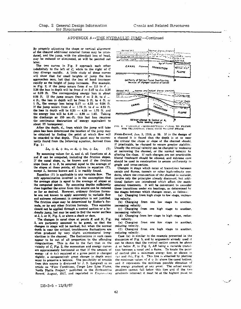
Chap. 2 General Design Information Cnn& and Related Structures fcr Structures
APPENDIX A--THE HYDRAULIC JUMP--Continued
By properly adjusting the shape or vertical alignment of the channel additional external forces may be intro. duced, and the jump. with the attendairt loss of head, may he reduced or eliminated, as will be pointed out later.
The two curves in Fig. 2 approach each other indefinitely to the left of C, while to the right of C they diverge rapidly. A little study of these curves will show that for small heights of jump the loss approaches zero, but that the loss of head increases rapidly as the height of jump increases. For example, in Fig. 2. if the jump occurs from d = 2.5 to d _ 3.38 the loss in depth will be from d = 3.47 to tI.= 3.38 or 0.09 ft. The corresponding energy loss is about 0.05 ft. If the jump occurs from d = 2 ft. to d L. 4 ft., the loss in depth will be from 5 ft. to 4 ft. 01 1 ft., the energy loss being 5.17 - 4.33 = 0.84 ft. If the jump occurs from d = 1.75 ft. to d = 4.55 ft. the loss in depth will be 6.30 - 4.55 = 1.75 ft. and the energy loss will be 6.40 - 4.80 = 1.60. Taking the discharge as 150 sec.-ft. t-his last loss requires the continuous destruction of energy equivalent to about 27 horsepower.
After the depth, &. from which the jump will take place has been determined the location of the jump may be obtained by finding the point at which flow will be retarded to that depth. This point may be conven- iently found from the following equation, derived from Fig. 1:
Ls, + d. + hue = dr + hub + Ls, (7)
By assuming values for d. and dt, all functions at A and B can be computed, including the friction slopes. If the canal slope. a”. be known and if the friction slope fForn A to R. be assumed’equal to the average of the slopes at these points, all factors in equation (7), except t, become known and L is readily found.
Equation (7) is applicable to any variable flow. The only approximation involved is in the assumption that the average slope is equal to the average of slopes at the computed points. By assuming depths sutliciently close together the error from this source can he reduced as far as desired. However, ordinary friction formu- h are not known to apply accurately to, variable flow and extreme refinement in computation is not justified. The friction slope may be determined by Kutter’s for- mula. or by anjr other friction formula. This equation should not be applied through a control section or a hy- draulic jump, but may be used to find the water surface at J. L or N, Fig. 5, or above a check or dam.
The changes in canal slope at points K and N. Fig. .5. are purposely assumed to be great, so that the changes in stage will be marked, but when the normal depth is near the critical, troublesome fluctuations are often produced by very slight unintentional irreg- ularities in the channel. The fluctuations in such cases appear to be out of all proportion to the offending irregularities. This is due to the fact that in the vicinity of C, Fig. 2, the momentum and energy cur\-es are approximately horizontal so that if the amount of energy (d + l(r) required at a given point is changed slightly, a comparati\.el.v great change in depth must occur to preserve a balance. The porribility of trouble from this source is di.scussed by J. S. Longwell in an article on “Flow Conditions, Congo Low Line Flume. Sorth Platte Project.” published in the Crcfn~~(i~r Rero&+, r\ugu&, 1917, and reprinted in f..~c:/i,r* < r.;~/
(b) Met alted (0 bntrd ot A; Flume badmg poprly
News-Rrrord. Jan. 3. 1318. p. 38. If in the design of a channel it is found that the depth is at or nenr the critical the shape or slope of the channel shoulcl. if practicable, be changed to secure greater stability. Usually the critical velocity can be changed by widening or narrowing the channel, or the normal velocity 1,) altering the slope. If such changes are not practicable. liberal freeboard should be allowed. and extreme rare should be used in construction to secure uniformity in grade and cross-section.
Changes in stage which occur at transitions hetween canals and flumes, tunnels or other high-velocity con. duits. where the cross-.section of the channel is variable. involve only the principles already discussctl. but nddi- tional factors are introduced which afiect the mrth- ematical treatment. It will be convenient to consider these transitions under six headings, as determined II! the stages between which changes occur, as follows:
(a) Changing from high stage to low stage. increas- ing velocity.
(b) Changing from one low stage to another. increasing velocity.
(c) Changing from one high stage to another, increasing velocity.
(d) Changing from low stage to high stage, reduc- ing velocity.
(e) Changing from one low stage to another, reducing velocity.
(f) Changing Cram one high stage to another, reducing velocity.
Case (a) is similar to the example presented in the discussion of Fig. 5. and by arguments already used it can be shown that the control section cannot be above A or below R, in Fig. G, AR being u variable tranri- tion between a canal end :I flume. TO locate the ~OIIII of con!rol plot ;L minimum energy line, ar shown 111 ,a) and II,), Fig. G. This line is obtained by plottina the minimum v&&e* of cl -+- kr above the canal hottom. and it represents the minimum possible elevation lpf the energy gradient at any point. The actual energ:’ gradient cannot fall below this line vl?d if the two Cratlientr inter+ct it must be at the highest point nrl
.- -
DS-3-5 - 12/8/67 62
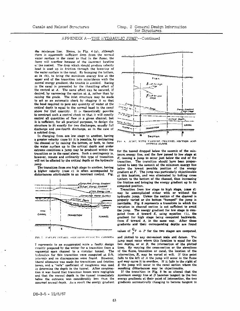
Canals and Related Strwturss !.: hap. 2 Genernl Design Information for Structures.
APPENDIX A--‘T!!E i-XDiiAULIC JUMP--Continued
the minimum line. Hence. in Fig. 6 (a>. although there is apparently sufficient drop from the normal water surface in the canal to that in the flume. the ;iumc will overflow hrcausc of the incorrect location o! the control. The drop which should produce velocity head is used up in friction through the lowering of the water surface in the canal. Fly humping the bottom. as in th), to bring the minimum energy line at the upper end of the transition into coincidence with the normal energy gradient, the trouble is avoided. Racing in the canal is prevented hy the throttling effect of the control at A. The same effect can be secured, if desired. by narrowing the section at A. rather than hy raising the grade. The inlet structure may be made to act as an automatic check by shaping it so that the head required to pass any quantity of water at the critical depth is equal to the normal head in the canal above for that quantity. It is theoretirrlly possible to construct such a control check so that it will exactly control all quantities of flow in a given channel, but it is sufficient. for all practical purposes, to design the structure to fit exactly for two discharges, usually full discharge and one-fourth discharge, as in the case of a notched drop.
In changing from one low stage to another, having a greater velocity (case b) it is possible, by contracting the channel or by raising the bottom, or both, to force the water surface up to the critical depth and under extreme conditions a jump may be produced within the transition or in the canal above. Such a contingency is, however, remote and ordinarily this type of transition will not be effected by the critical depth or the hydraulic jump.
The transition from one high stage to another, having a higher velocity (case c) is often accompanied by diurbances attributable to an incorrect control. Fig.
- ! ! CANAL : TRANSITION
7 represents to an exaggerated scale a faulty. design r:cently prepared by the writer for a transition from a segmental open channel to a circular tunnel. The II?-draulics for this transition were computed at 2-ft. intervals and no discrepancies were found. However, liberal allowance was made for transitions and friction losses. and a “safe” coeficient of roughness was used io determine the depth in the tunnel. After construc- tion it was found that transition losses were negligible and that the normal depth in the tunnel immediately below the entrance was considerably less than the assumed normal depth. As a result the energy gradient
for the tunnel dropped below the summit of the min- imum energy line, and the flow passed to low stage at E, causing a jump to occur just below the end of the transition. The transition should have been pmpor- tioned to keep the summit of the minimum energy line below the lowest possible position of the energy gradient at F. The jump was particularly objectionable at this location, and was eliminated by bolting cm.% timbers to the bottom of the channel, thus increasing the friction and bringing the energy gradient up to its computed position.
Transition from low stage to high stage, (ease d) may be accomplished either with or without the hydraulic jump. Unless the section of the channel is properly varied or the bottom “humped” the jump is inevitable. Fig. 8 represents a transition in which the variation in channel section is not sufficient to avoid the jump. The energy gradient for low stage is com- puted from A toward E. using equation (1). the gradient for high stage being computed backwards, from E toward A, in the same way. After these gradients and their corresponding depths are found
values of r) V c7
+ P for the two stages are computed,
and plotted to any convenient scale and datum. The jump must occur where this function is equal for the two depths, or at B, the intersection of the plotted lines. By varying the cross-section or the elevations of the flume, transition or canal, the location of the intersection, B, may be varied at will. If this point falls to the left of A the jump will occur in the flume and may cause it to overflow. If it falls to the right of E the jump will occur in the canal section where the resulting digturbances may be chjectionable.
If the transition in Fig. 8 be so altered that the minimum energy line at D becomes tangent to the two energy gradients at their point of intersection, the two gradients automatirally changing to become tangent tc
DS-3-5 - 12&‘67 63
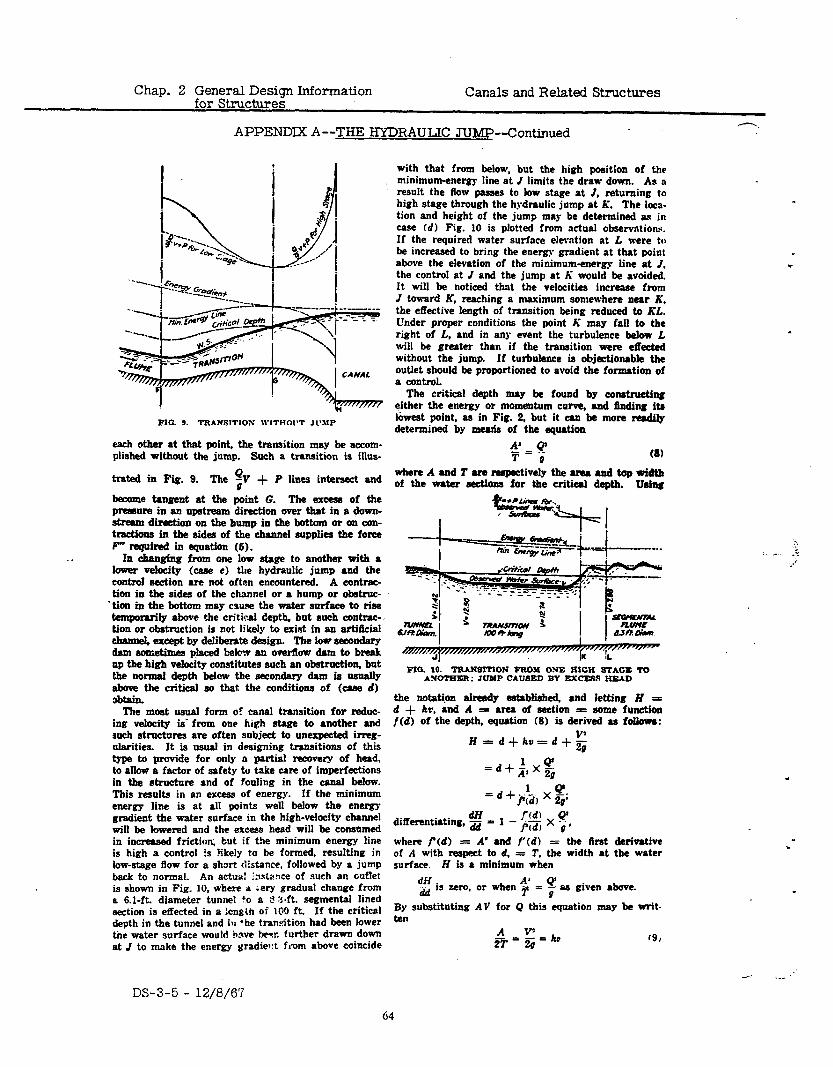
Chap. 2 General Design Information for Structures
Canals and Related Structures
APPENDIX A--THE HYDRAULIC JUMP--Continued -.
FIG. 9. TRANSlTlOS WITHOI’T Jt’UP
each other at that point. the transition may be accom- plished without the jump. Such a transition is illus-
trated in Fig. 9. The $ + P lines in§ and
become tangent at the point G. The excess of the p~ssure in an upstream direction over that in a down- stream direction on the bump in the bottom or on con- tractions in the aides of the channel supplies the force F” required in equation (6).
In changing from one low stage to another with a lower wdooity (case c) the hydraulic jump and tbe control section are not often encountered. A contmc- tion in the aides of the channel or a hump or obstruc-
* tion in the bottom may cau.se the water surface to rise temporarily above the critical depth, but aucb contrac- tion or obstruction is not likely to exist in an artiiicial clmnd, except by deliberate design. The low aeaondary dam aometinwa placed belo- an overgow dam to break np the high v&city constitutes such an obstruction, but the normal depth below the secondary dam is usually above the critical so that the conditions of (case d) 3btain.
The moat usual form of canal transition for reduc- ing velocity is’ from one high stage to another and such structures are often subject to unexpected irreg- ularities. It is usual in designing transitions of this type to provide for only a partial recovery of head, to allow a factor of safety to take care of imperfections in the structure and of fouling in the canal below. This results in an excess of energy. If the minimum energy line is at all points well below the energy gradient the water surface in the high-velocity channel will be lowered and the excess bead will be consmned in inrressed friction; but if the minimum energy line is high a control is !ikely to be formed, resulting in low-stage flow for a short distance. followed by a jump back to normal. An actur: :xlr!:ce of such an cutlet is shown in Fig. 10, where a ;ery gradual change from a 6.1-ft. diameter tunuel l o a $3.ft. segmental lined section is effected in a lcnglh of ICXI ft. If the critics1 depth in the tunnel and in ‘he transition had been lower tne water surface would have hesr. further drawn down at J to make the energy gradie*:t ft-om above coincide
with that from below, but the high position of the minimum-energy line at / limits the draw down. As a result the flow passes to bw stage at J. returning to high stage through the hydraulic jump at ii. The loca- tion and height of the jump may be determined as in case Cd) Fig. 10 is plotted from actual observations. If the required water surface elevation at L were to be increased to bring the energy gradient at that point above the elevation of the minimum-mergy line at J. the control at J and the jump at K would be avoided. It will be noticed that the velocities increase from J toward K, reaching a maximum somewhere near K. the effective length of transition being reduced to KL. Under proper conditions the point ii may fall to the right of L, and in any event the turbulence below L will be greater than if the transition were effected without the jump. If turbulence is objectionabk the outlet should be proportioned to avoid the formation of a control.
The critical depth may be found by constructing either the energy or momentum curve, and Bnding its lowest point, as in Fig. 2. but it can be more radily determined by meads of the equation
A’ Q - t .- T o (8)
where A and T are respectively the ama and top width of the water sections for the critical depth. Using
FIG. 10. tRANSItION FRox ONE RICH stAot tD ANOtHER: JUMP CAUSED BY EXCESS HE.4D
the notation already established. and letting H = d + is, and A = area of section = some function f(d) of the depth, equation (8) is derived as followa:
H =d+hv=d+$
dH differentiating, ;s;i = 1 l-cd) 4 -pax,, where f(d) = A’ and f’(d) = the first derivative of A with respect to d, = T. the width at the water surface. H is a minimum when
dff Q’ _.. dd
is m-o. or when $ = 7 a9 given above.
gy substituting AV for Q this-equation may be writ- ten
A v-’ ~T=~=hll f9J
t
.
.
.
-
DS-3-5 - 12/8/67
64
Canals and Related Structures Chap. 2 General Design Information for Structures
APPENDIX A--THE KYDRAULIC JUMP--Continued
In a rectangular section of wrlth, b. A is eqrlal to bd, T is equal to b. and (8) may be reduced to
8’ - = b%PO(for rectangular sections) 0
(10)
from which d, is readily determined. Equation (9) reduces to the weii-known form
ho, = & (for rectangular sections) (11)
In a triangular section, where the ratio of T to d is X. equation (8) reduces to
- - ‘a-- (for triangular section) ‘*-’ 0 and (11) becomes
hv, = $L ‘(for triangular section) (1s)
Similar formubr may be deduced for any channeI having a known mathematiepl relation betwen A, t and
d, but generahy the resulting equations are of the $
deg.. and are complicated. and it is preferable to use equations (8) and (9) without further reduction. If d, is known and Q required these equations may be aoked directly, but if & ia the unknown the solution can best be made by trial.
Valuable assistance in the preparation of this paper has been rendered by D. C. McConaughy and W. II. NaIder and other engineers in tbe Denver Mice of the Reckmat;on Servicfz
See Figures 18 and 19 (Paragraph 2.29) for Energy LGSS and Relations between Variables in a Hydraulic Jump.
DS-3-5 - 12/8/67 65
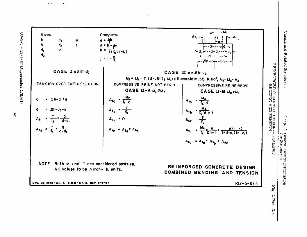
Canals and Related
Structures Chap.
2 G
eneral Design
Information
for Structures
REINFORCED
CONCRETE
DESIGN--CO
MBINED
BENDING
AND TENSIO
N Fig.
1 Par. 2.4
.
c In . G
I- I
DS-3-5 - 12/8/67
(Supersedes l/6/61)
67
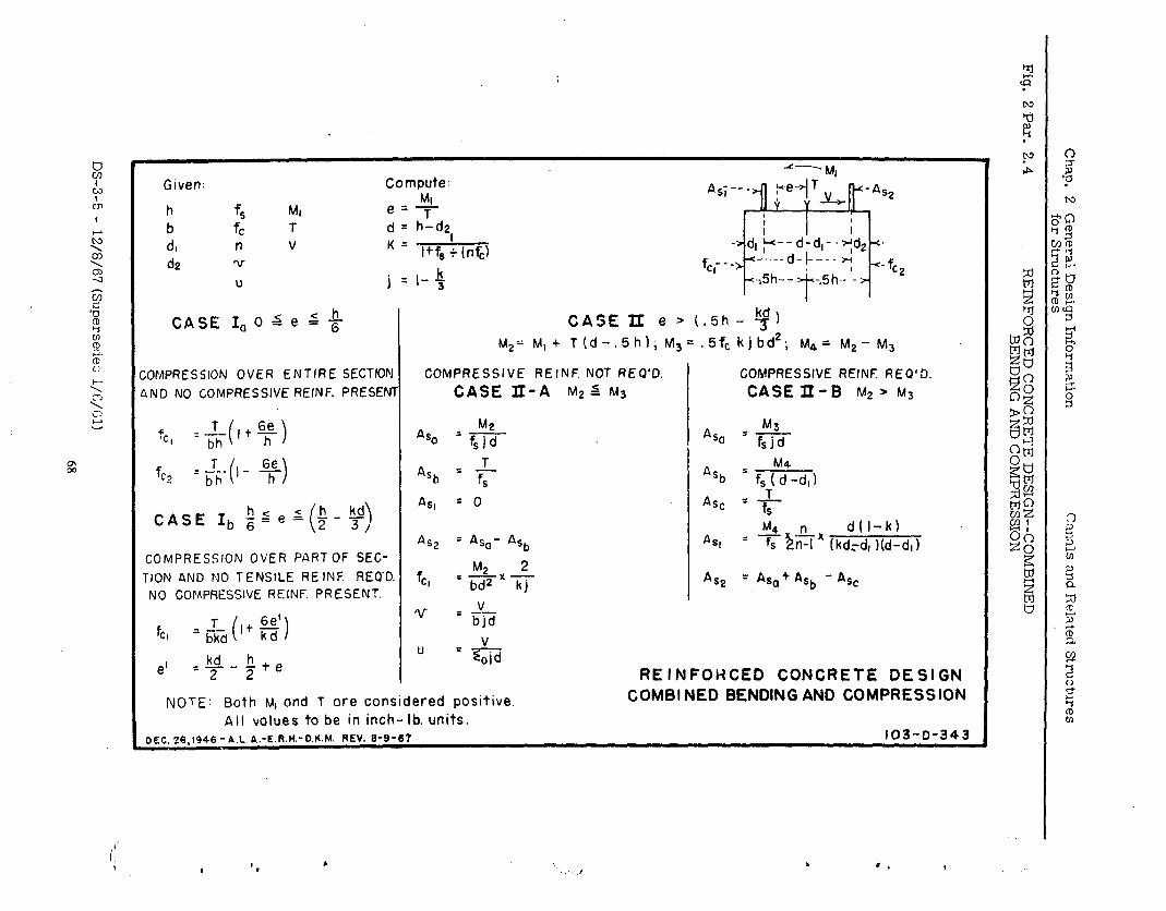
Given: Compute: Ml
A,;--- Fe-
h f, MI e z- F
h:de v-
‘-B , 4T; v Y
r-As2
b fc T d= ; 1 I
d, n V K= -ad, y--d-d,--Td2-+ & v
I+fs : (r&l fcl---g----d-C--- z-, <-f
u j cl-5 +5f-,-- ’ ;5h.- ‘_ > T
CC?
CASE I, 0 s e 6 +- CASE II e .’ (.5h - y)
M2= MI + T(d-.Shl; M,= .5fc kjbd2; t&= r.,12- ~~
;OMPRESSION OVER ENTIRE SECTION COMPRESSIVE REINF. NOT REO’D. COMPRESSIVE REINF REQ’D. PND NO COMPRESSIVE REINF. PRESENT CASE II-A M2 s M3 CASEII-B fd2 > M3
f :$,+$g Aso
M2 ‘Cl =f,jd ASo
M3
=fsjd
f T C?
=.&-(,- y) Ash = f, Aq, = f, (y-d, 1 T
CASE Ib $ges $-y, ( ’
ASI = 0 Asc = f
M4 “n d(l-k)
AS2 = Aso- Ash ASI COMPRESSION OVER PARTOF SEC-
= r, hn-1 (kd,-d, lid-d,)
TION AND NO TENSlLE RE INF. REQ’D. fee, M2 2 =zxhj AS2
NO GOMPRESSIVE REINF. PRESENT. = Aso + Ash - kc
fc, =$&It f$) u = +L$
-k+e U
e’ =kd
=&
2 2
NOTE: Both M, ond T ore considered positive. All values to be in inch-lb. units.
DEc.26,1946-ALA.-E.f?.H.-D.K.M. REV. S-S-67
REINFOHCED CONCRETE DESIGN COMBI NED BENDING AND COMPRESSION
103-D-343
c
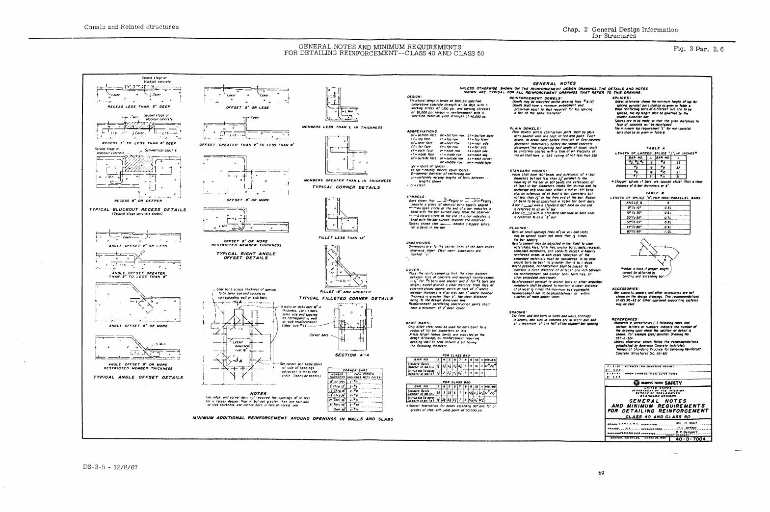
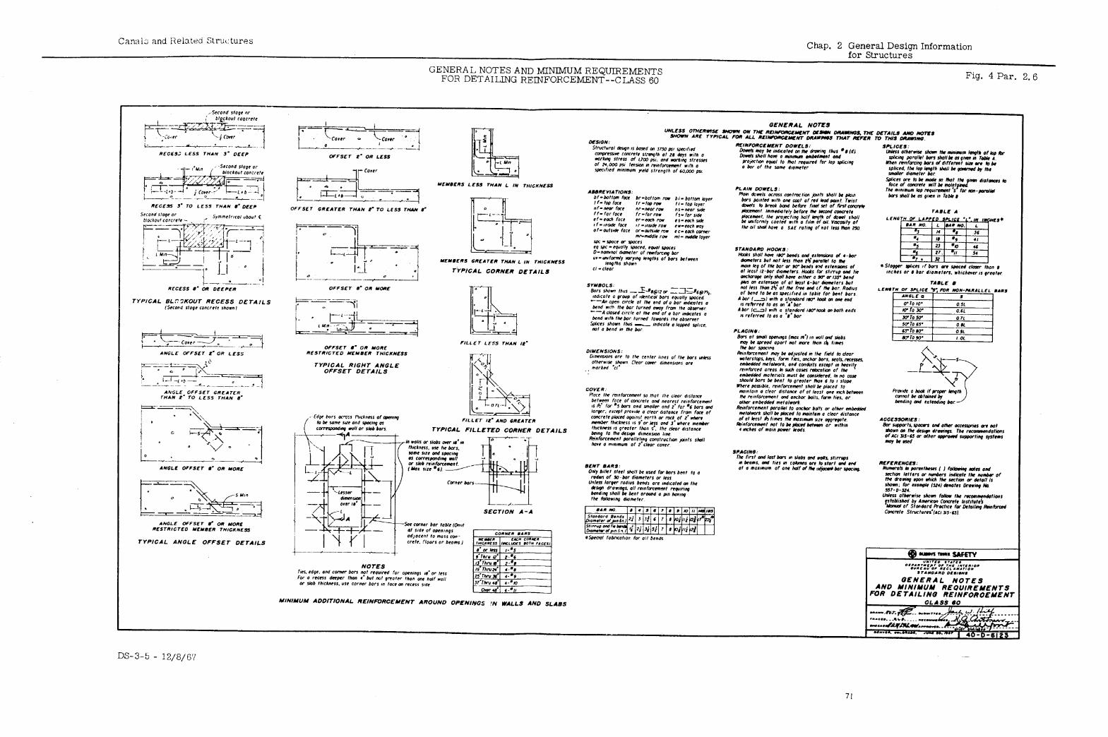
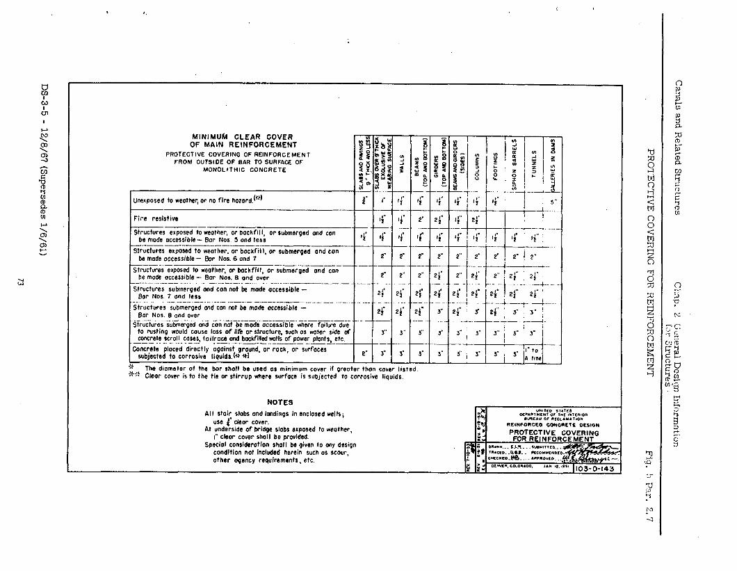
Canals
and R
elated Structures
Ch3.p.
2 G
cl!eral D
esicrr, Inform
ation for
Structures
PRO
TECTIVE
CO
VERIN
G
FOR
R
EINFO
RC
EMEN
T
!WVO
N
I S31Y31
3,VdLmS
9NIYIBM
m
3Am
t~X3 --
WN
L 4 n3m
sams
SS
31 ON
V YOIYI
.6 SO
NW
d O
NV S
6VlS
‘*
!: P:.l.r. 2. ‘7
DS-3-5
- 12/8/67
(Supersedes l/6/61)
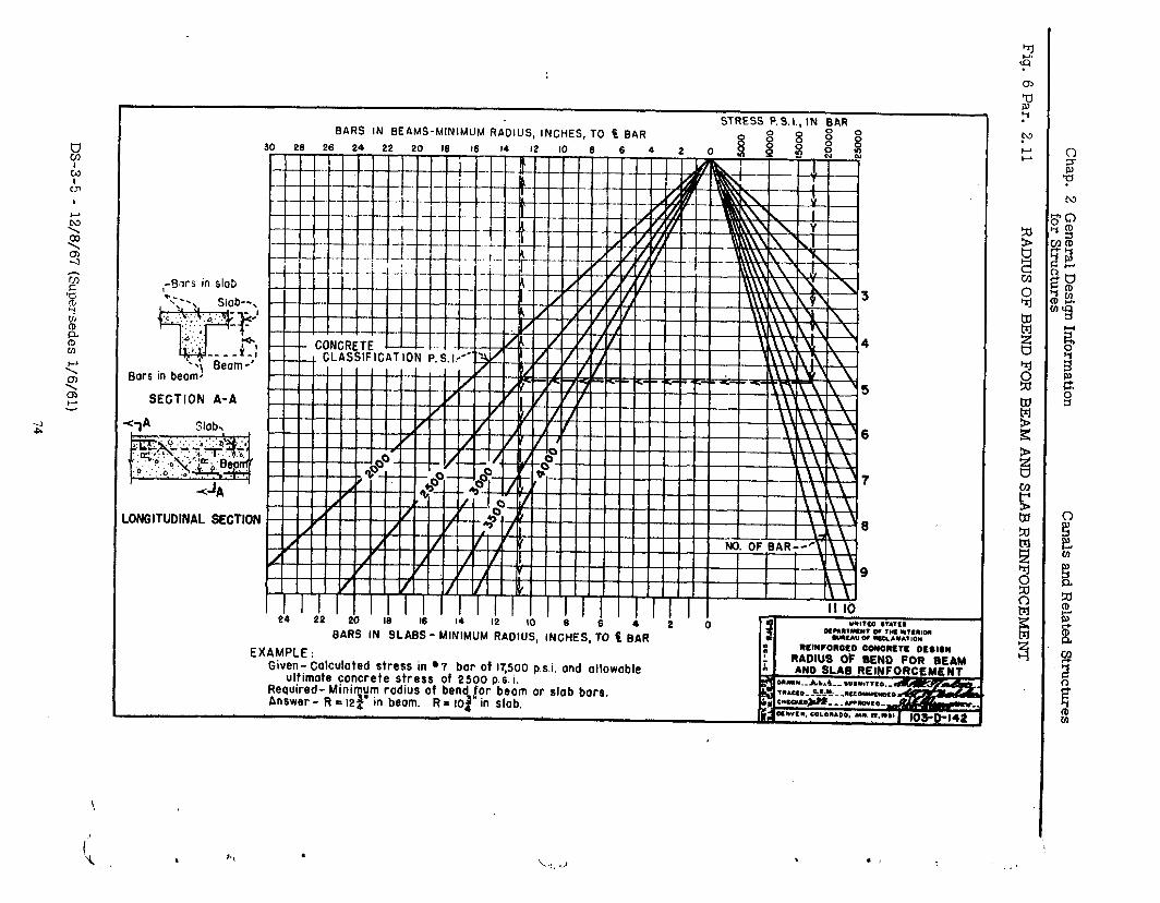
Chap. 2
General
Design Inform
ation for
Structures Canals
and Related Struct~es
Fig. 6 Par.
2.11 RADIUS
OF BEND
FOR
BEAM
AND SLAB
REINFORCEM
ENT
DS-3-5 - 12/8/67
(Supersedes i/6/61)
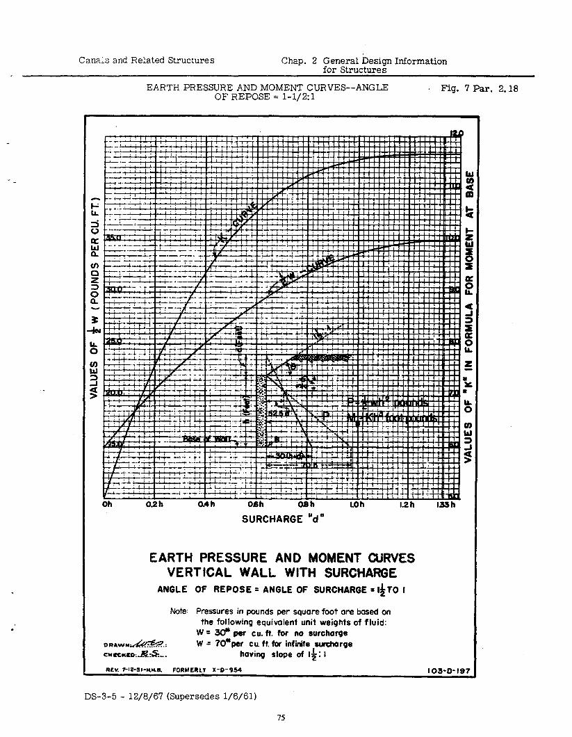
Can&s and Related Structures Chap. 2 General Design Information for Structures
EARTH PRESSURE AND MOMENT CURVES--ANGLE OF REPOSE = l-1/2:1
Fig. 7 Par. 2.18
EARTH PRESSURE AND MOMENT CURVES VERTICAL WALL WITH SURCHARGE
ANGLE OF REPOSE = ANGLE OF SURCHARGE = l&TO I
Note: Pressures in pounds per square foot are based on the following equivalent unit weights of fluid:
W = @ per cu. ft. for no surcharge DRAW”#.: W = 7O’per cuft.fw infinite sufchorge CYWCXD:.l&S... having slope of I$: I
REV. 7-It-sa-nwa FORHERLI X-D-954 103-o- I97
DS-3-5 - 12/8/67 (Supersedes l/6/61)
75
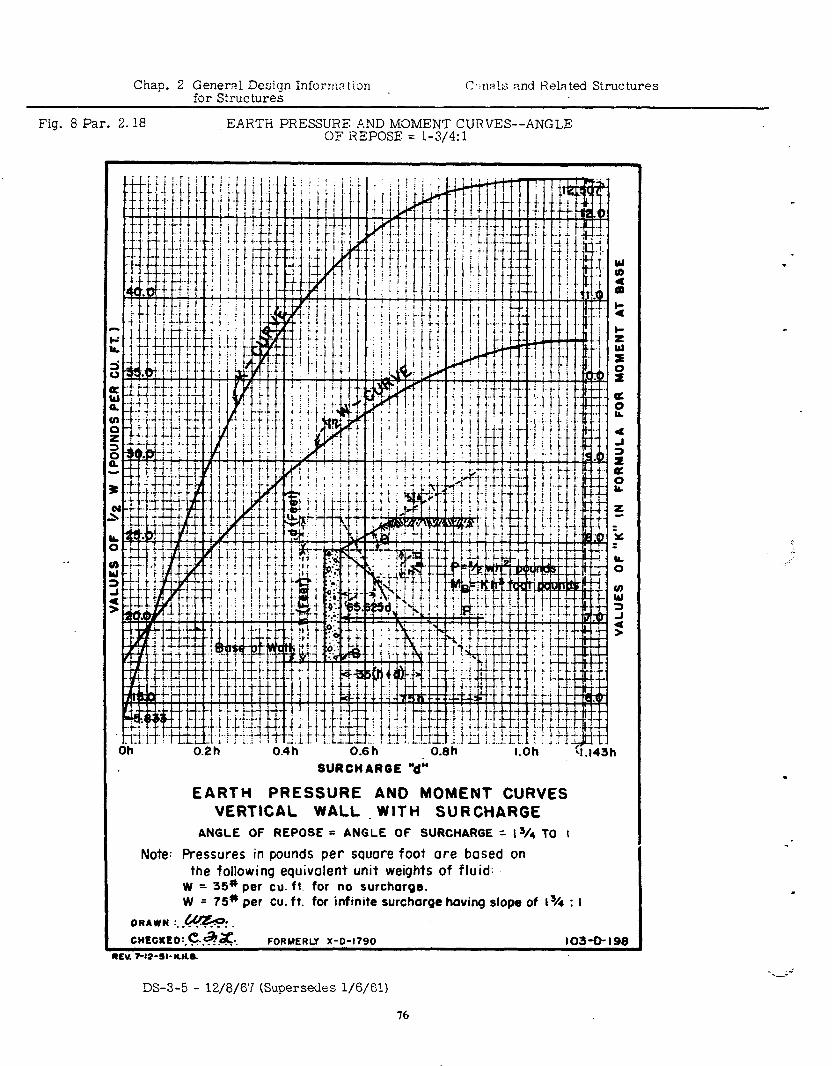
Chap. 2 General Design Inforrm tim C,:n~ls md Related Structures for Strut tures
.
Fig. 8 Par. 2.18 EARTH PRESSUHE b.ND MOMENT CURVES--ANGLE OF REPOSE = l-3/4:1
SURCHARGE +
EARTH PRESSURE AND MOMENT CURVES VERTICAL WALL WlTH SURCHARGE
ANGLE OF REPOSE= ANGLE OF SURCHARGE = l3/4 TO I
Note: Pressures in pounds per square foot ore bosed on the following equivalent unit weights of fluid:
W = 35* per cu. ft. for no surcharge. W = 75* per cu. ft. for infinite surcharge having slope of 13/r : I
ORAWN :. .&%?:. CHECKED:.&+.&. FORUERLY X-O-1790 103-O-198
.C., w-*--11-” Y m
.
c
.
DS-3-5 - 12/8/6’7 (Supersedes l/6/61)
76
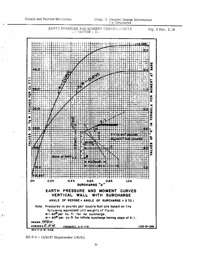
Canals and Related Strwtures Chap. 2 Gcwral Design Information f 11 IXructures .
Fig. 9 Par. 2.18
. .’
Oh 0.2 h 0.4 h 0.6 h 0.8 h I-Oh SURCHARGE “d ”
EARTH PRESSURE AND MOMENT CURVES VERTICAL WALL WITH SURCHARGE
ANGLE OF REPOSE = ANGLE .OF SURCHARGE = 2 TO I
Note: Pressures in pounds per square foot ore based on the following equivalent unit weights of fluids
W = 40*per Cu. ft. for no surcharge. w = 80++ per cu. ft. for infinite surcharge having slope of 2: I.
DRAWN .@6+. C?ECKED.e..~.g. FORMERLY X-D-1791 I 03-0-19s REV.T-12-s- nne.
DS-3-5 - 12/8/67 (Supersedes l/6/61)
77
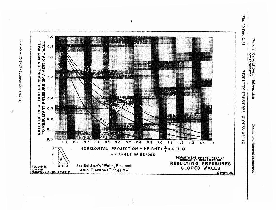
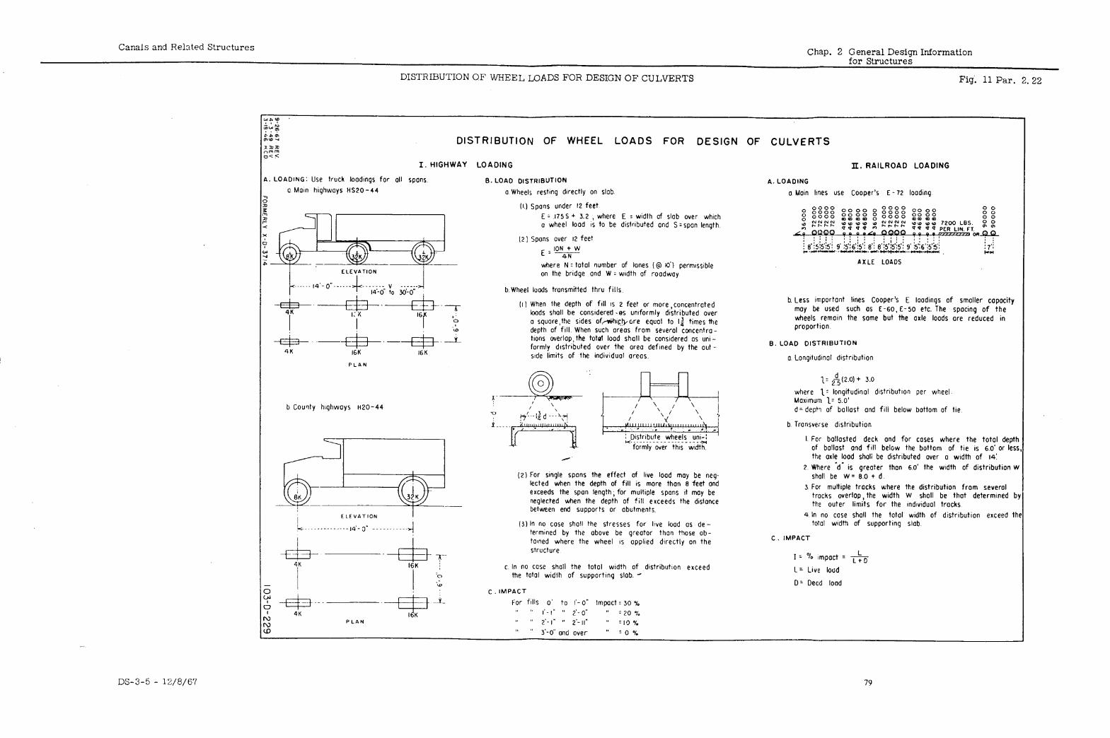
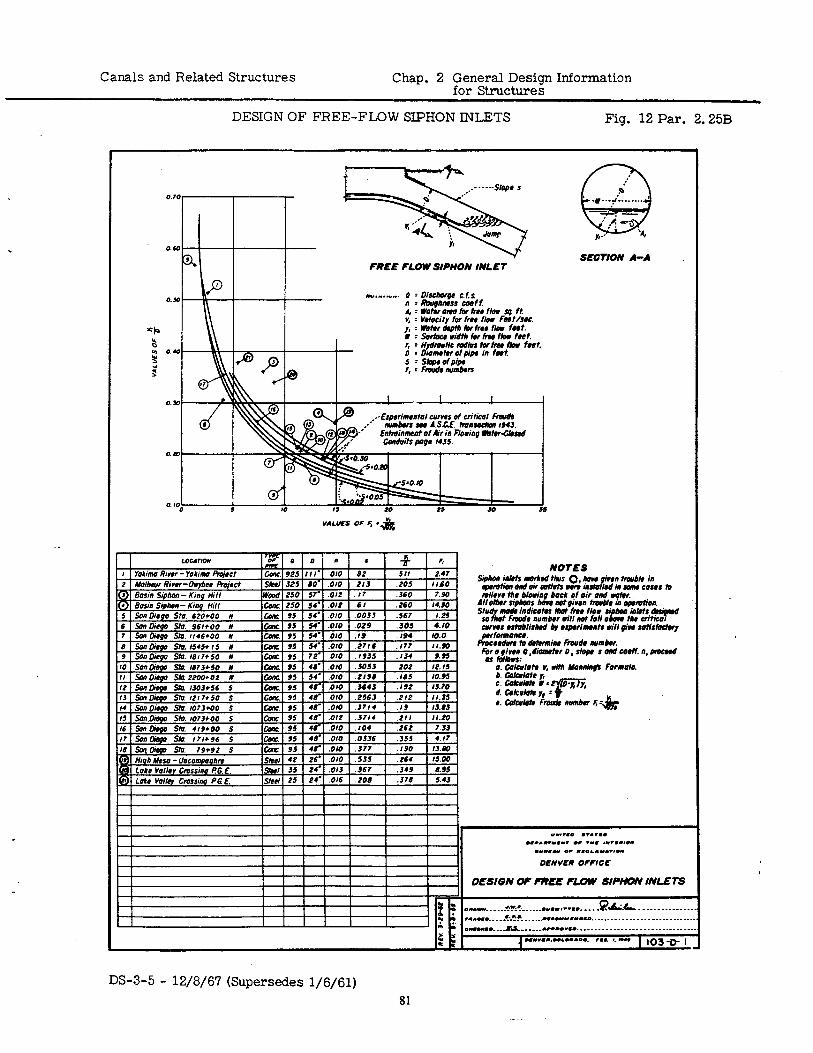
Canals and Related Structures Chap. 2 General Design Information for Structures
DESIGN OF FREE-FLOW SIPHON INLETS Fig. 12 Par. 2.25B
SECTION A-A FREE FLOW SIPHON INLET
*Y.-*.“*. 0 : oishorqo c.f.s n * Rouphnrss co&f. *:wotwomolbrhrrflou sg ft v, - Velocity for fm flow Fw~/sN. y, : wtor &pm Ibr fro0 fbm font. I : Swhco widfh for hw flolr fret. r, : Hydfodic r&us fwfm fbw frrt. 0 : Diomhr of pipa in fwt 5 = SrOprofpipr f, : Fm& numberr
DS-3-5 - 12/8/67 (Supersedes l/6/61) 81
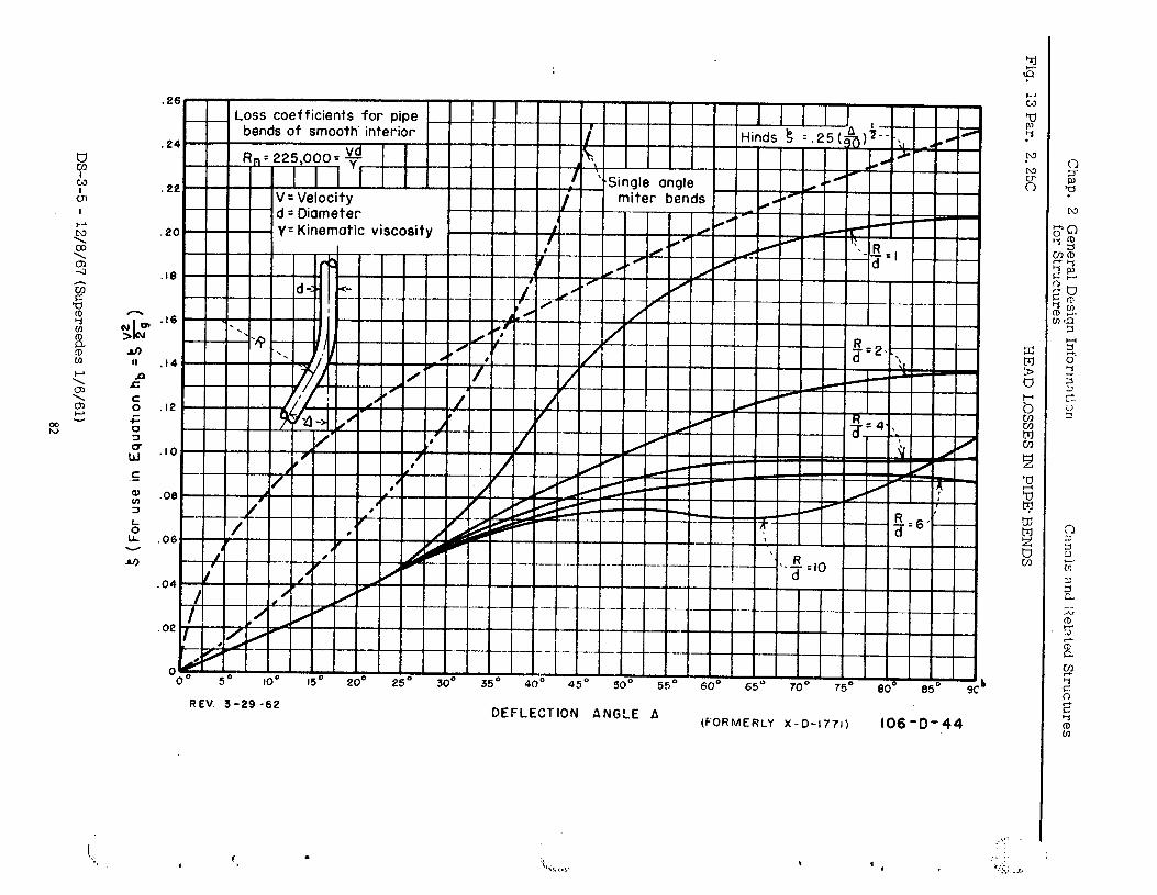
Chap. 2
General
Design Inforln:>ti:;r~
for Structures
Cnnclls :jnd
l?elnted Structures
. Fig.
13 Par. 2.2%
HEAD
LOSSES IN
PIPE- BENDS
0 Y)
0
w
0 x
0 b
0
i ;
:.;: ..:;:
. .-
J.“
(3s’ qq
uo!$onb3 U! asn
JOj) $
DS-3-5 - 12/8/67
(Supersedes l/6/61)
82
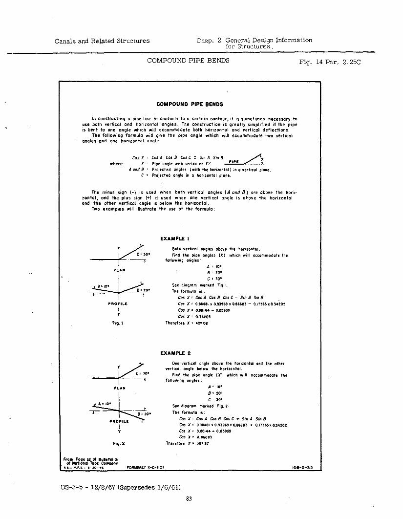
Canals and Related Structures Chap. 2 General Design Information for Structures
COMPOUND PIPE BENDS Fig. 14 Par. 2.25C
COMPOUND PIPE BENDS
In constructing 0 pipe lme to conform to o certain contour, it IS sometimes necessary to use both vertical ond horizontol ongles. The construction is greotly simplified if the pipe is bent to one ongle which will occommodote both horlzontol ond vertical deflectlons.
The following formula will give the pipe angle which will occommodote two vertical angles ond one horizontol ongle:
Cos X = Cos A Cos B Cm C + Sm A Sin B where X : Pipe ongle with vertex on YY.
A ond 8 = Projected angles (with the horizontal) in o vertml plone C : Projected angle in o horaontol plonc.
The minus sign (-) IS used when both vertical onqles (.d and 8) ore obove the hori- tontol, ond the plus sign (+I IS used when one vertical angle is oh?ve the horizontol and the other vertical ongle 1s below the horizontal.
Two exomples will illustrate the use of the formula:
EXAMPLE I
Both vertlcol angles above the horaontol. which will accommodate the
PLAN
PROFILE I
Y
Fig. I
COS X : 0.96461 x 0.93969 I 0.66603 - 0.17365 x 0 34iO2
cos x : 0.60144 - 0.05939
COS X = 0.74205
Therefore X c 42*06
EXAMPLE 2
One vertical onple above the horizontol ond the other vertlcol angle below the horizontal.
following u~9les : Fmd the pipe on9le (Xl which will accommodate the
PLAN A : 100
I 6: 200
I toS x - 0.90461 x 0.93969 x 0.66603 + 0.17365 x 0.34202
;
Fig.2
cos x : 0.60144 + 0.05939 I% X = 0.06063
Therefore X - 30035
From Pogc PC of Bulletin LI OF National Tube bmpany
l .e.- v.*.s.- t-7.0-., FORNERLY X-O-1101 106-O-32
DS-3-5 - 12/8/67 (Supersedes l/6/61)
83
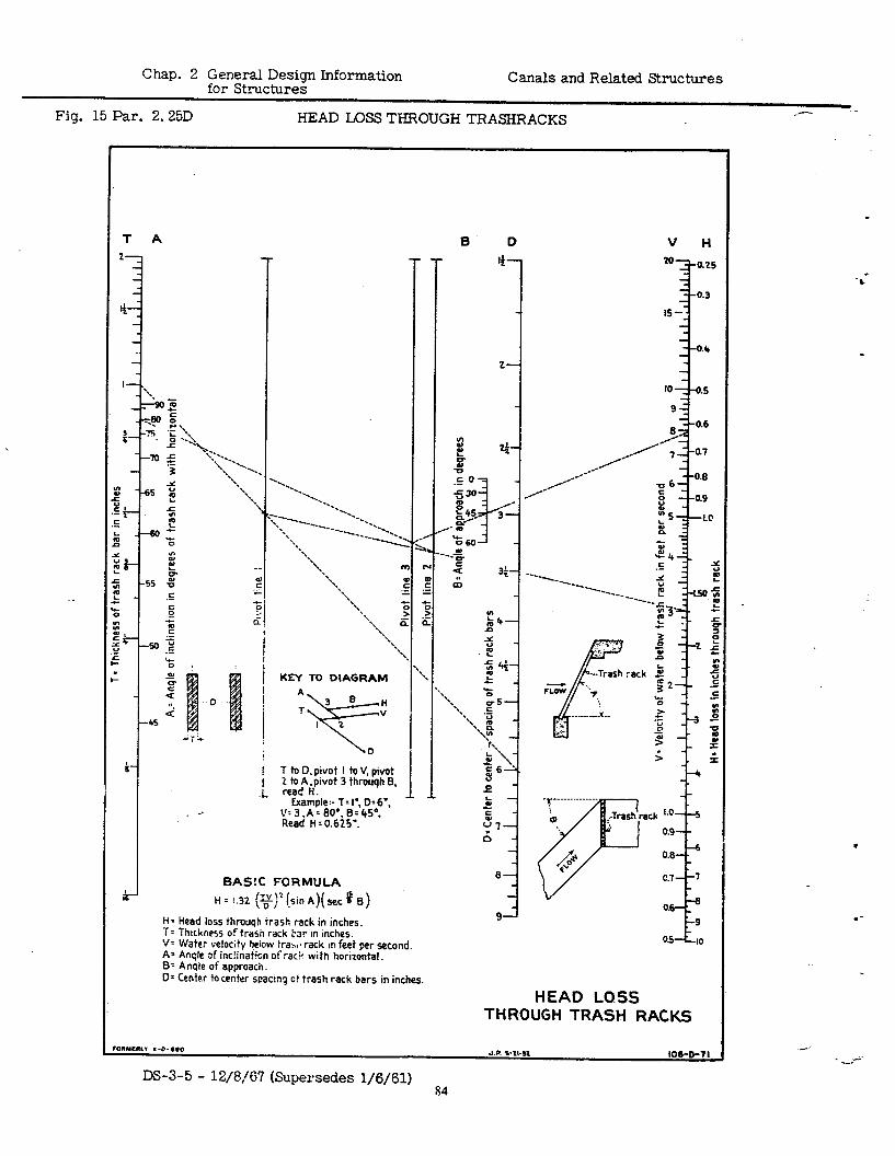
Chap. 2 General Design Infwmation for Structures
Canals and Related Structures
Fig. 15 Par. 2.25D HEAD LOSS THROUGH TRASHRACKS .--
: I -0 3
I
; 2
T to D, pivot I tu V, pivot
.i- read H. 2 to A 1 pivot 3 throuqh 6.
Example:- T= I’, D=6’, 11
V:3.A=80e.B=453 Read H : 0.625”.
BAS!C FORMULA
H = 1.32 (v)‘!sin A)( set a 6) V OS
yr ‘J= A= B=
Head loss throuqS trash rack in inches. Thtckness of trash rack tar in Inches. Water velocity b&w traw rack in feet per second. Anqle of inc!inaiion of rat? with horizontal. Anqie of approach.
D= Center to center scacmq cf irash rack bars in inches.
HEAD LOSS THROUGH TRASH RACKS
I”YCIL. x-o- ‘,O J.P. s-11-12 106~D-71
m-3-5 - 12/8/6’7 (Supersedes l/6/61) 84
.-
-*
_ . - . - -
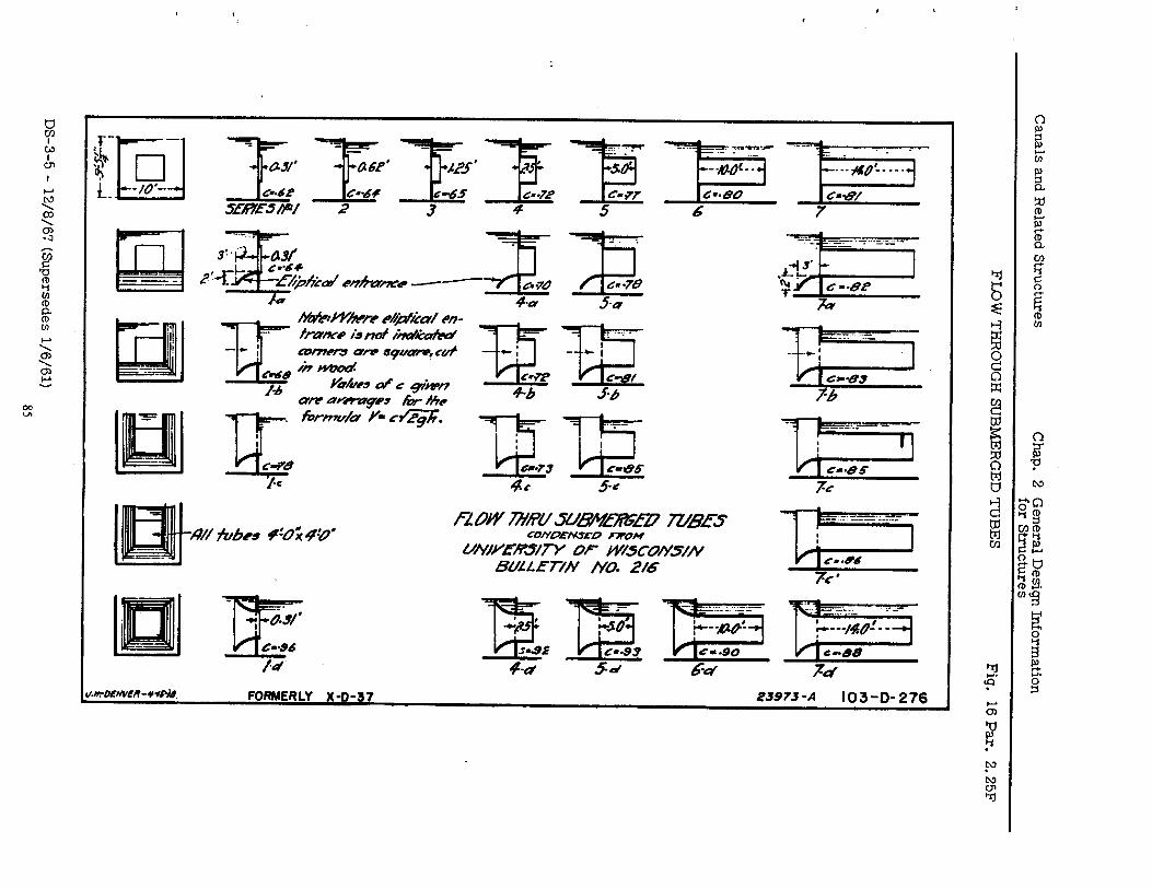
Canals and Related
Structures Chap.
2 G
eneral Design
Information
for Structures
- FLO
W
THROUG
H SUBM
ERGED
TUBES Fig.
16 Par. 2.25F
DS-3-5 - 12/8/6?
(Supersedes l/6/61)
85
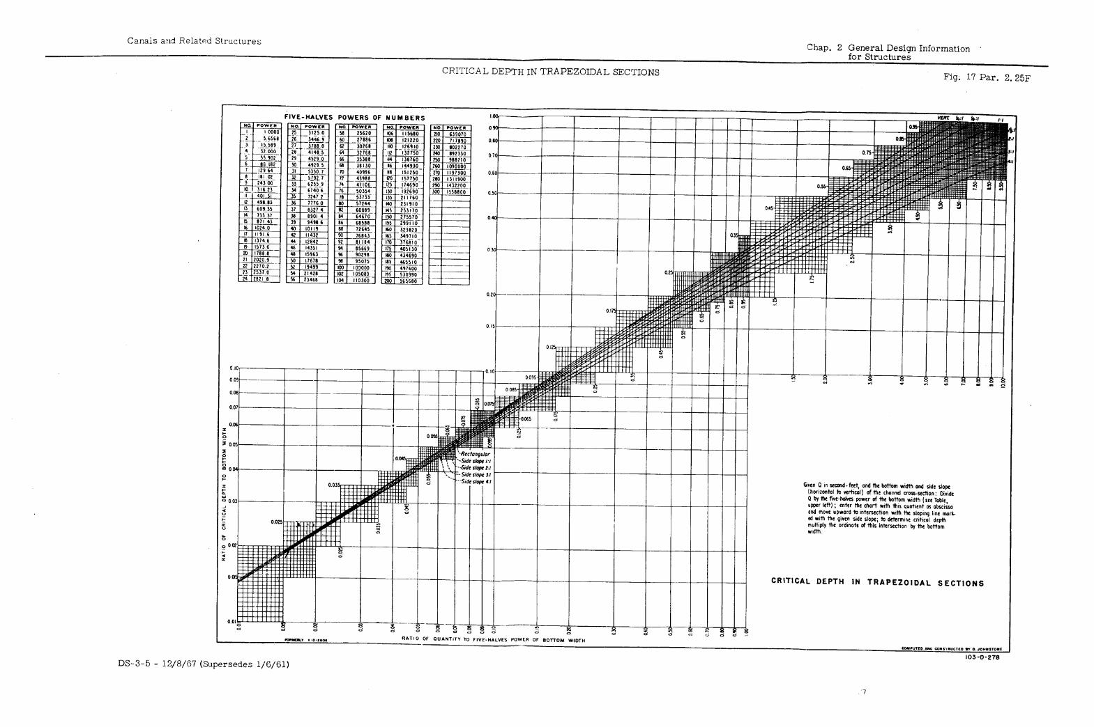
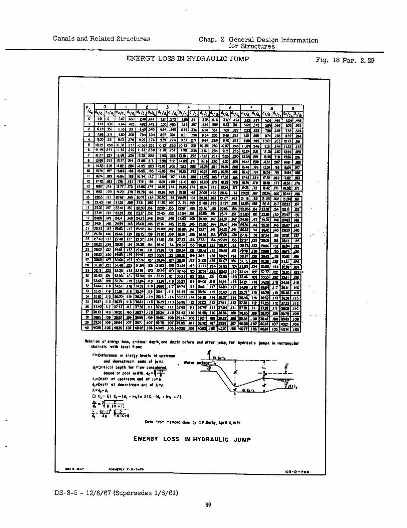
Canals and Related Structures Chap. 2 General Design Information for Structures
ENERGY LOSS IN HYDRAULIC JUMP . Fig. 18 Par. 2.29
Relation Of Cnrpl lo%, critical depth, and depth bafore and after jemp, for hydmulic jemps ia &nap&r channels with level floor.
F’Ditterenca in energy Iorels ot epstrean and dwestream reds of jump.
d&ritical depth for flow eoasidered. based an pool width. dc=w
d,=Depth at upstraom end of jump. d@apth 01 downstream end c4 jemp K=dpd, El. C,= El. 446, + hv,)= El.+Id, t hvs + F)
MO frOm mamorondum by C.R.Btiy, April 6.1939
ENERGY LOSS IN HYDRAULIC JUMP
DS-3-5 - 12/8/67 (Supersedes l/6/61)
89
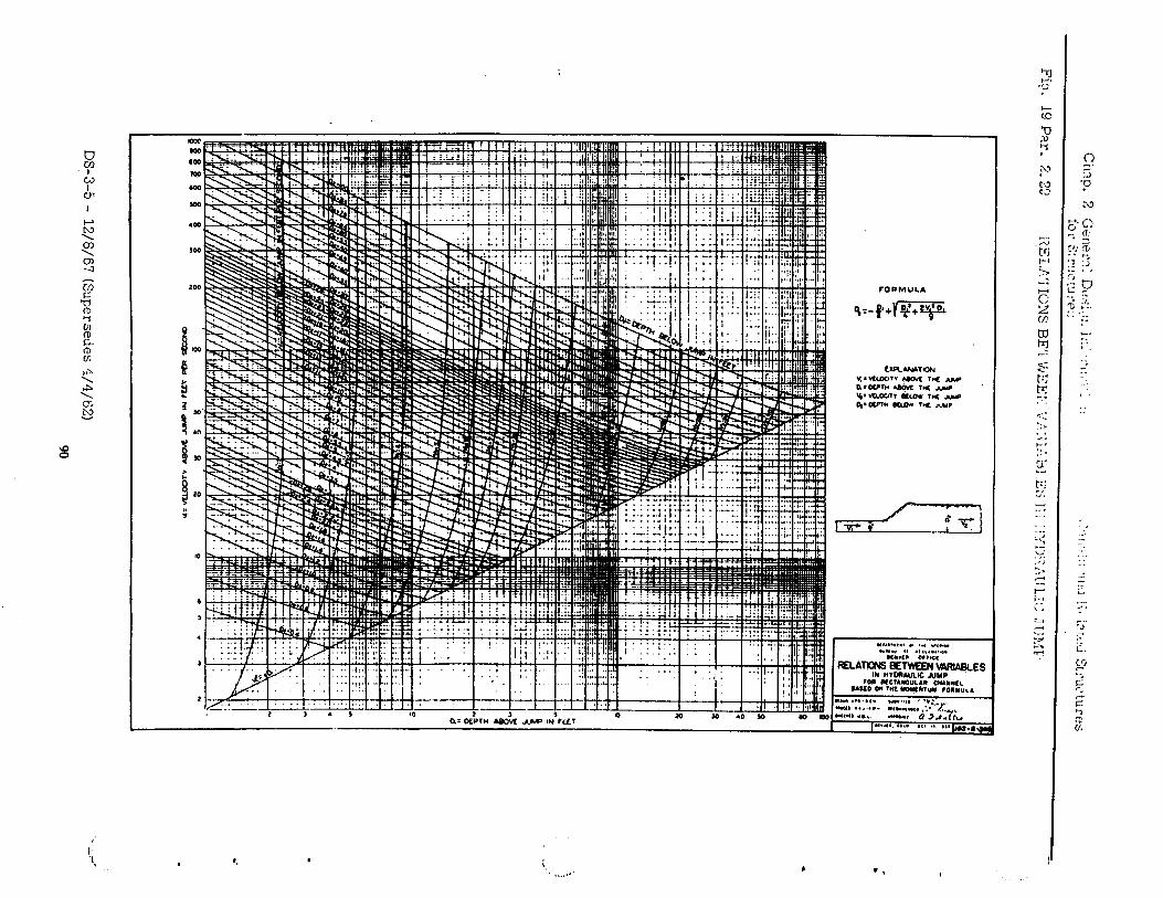
.-
-- u)
1
l .
.-
DS-3-5 -
12/S/67 (Supersedes
1/4/62)
90
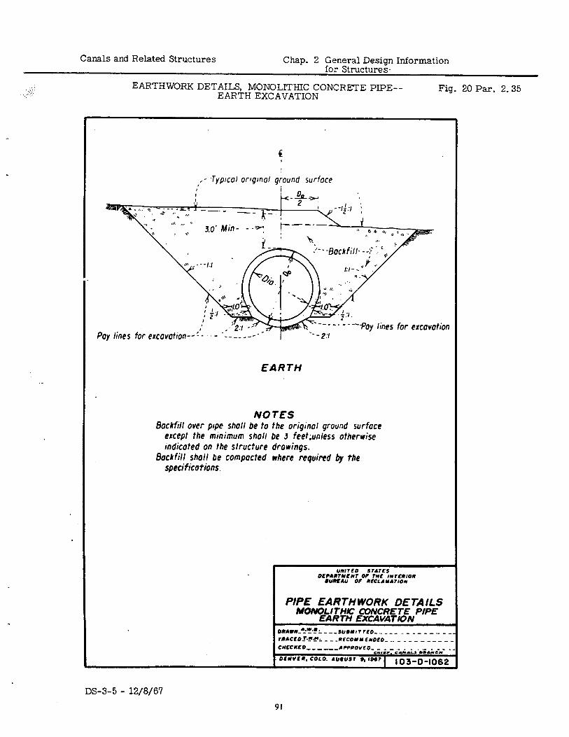
Canals and Related Structures Chap. 2 General Design Information for Structures.
, +:: I . ...; EARTHWORK DETAILS, MONOLITHIC CONCRETE PIPE--
EARTH EXCAVATION Fig. 20 Par. 2.35
e
I - .TyprcoI cmurnd around surface
POY line ‘5 for excavotion-- ‘ion
EARTH
NOTES Backfill over pipe shall be to the original ground surface
except the minimum shall be 3 feet;unless otherwise indicated on the structure drowinqs.
Bockfill shall be compacted where required by the specifications.
1 PIPE EARTH WORK DETAILS
I MONOLI T’HK: CVNCRETE PIPE EARTH EXCAVATION
ORAVN~A-w~N~ ------_ SU#mITrEo-.m _-- - -- --.- -- rRACEO~*.!‘E’ 2 - -~~fCo1YE*OEO~ ._ _ _ _ _ _ ___ _ CUECNLO me-,--ACP@OVEO- _ ._ - ._ _ . . ._ _ _ _ _
S” ,.C, SUIL, . ..“.z” OENVEI. COLO. AU‘US, ,, ,067
1 103-D-1062
DS-3-5 - 12/8/67 91
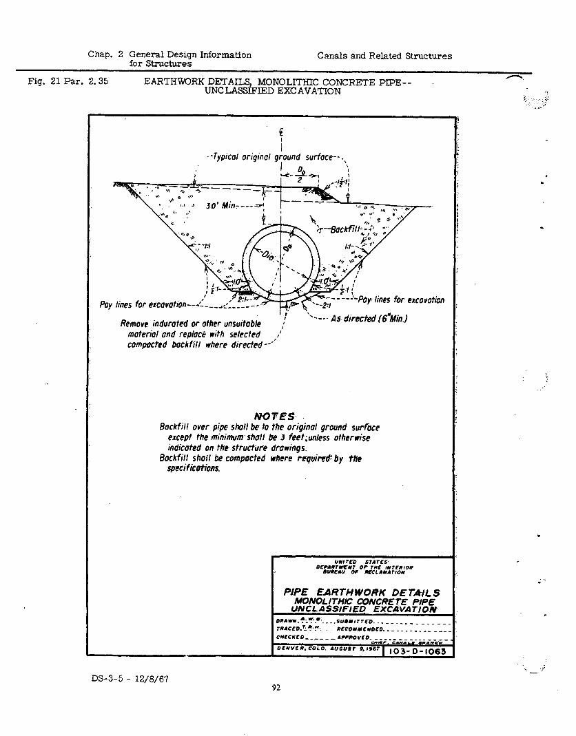
Chap. 2 General Design Information for Structures
Canals and Related Structures
Fig. 21 Par. 2.35 EARTHWORK DETAILS, MONOLITHIC CONCRETE PIPE-- UNCLASSIFIED EXCAVATION
n.
I: 5. , : :,:;:
.I ..,’ ._.‘. _
. -Typical original giound surface-- .,
----‘Pay: lines for excavation
Remove indurated or other unsuitable :’ .---- As directed (6”Min.j
materiol and rep/o&! with selected ’ campocted backfill where directed --*‘I
NQFES Backfill over pipe slwll be to the origin01 ground surroce
except the minimum shall be 3 feet;unless otherwise indicated on the structure drawings.
Backfill shall be compacted where requir& by fife specifications.
PIPE EARTH WORK D,E T&IL S MONOL JTHG CONCRE l-E PIPE
UNCLASSIFIEQ EXCA,VATION omw~. *r?.R.. _ _ .suewr rE.0. _ _ - _ _ _ _ _ _ _ _ _ _ _ TRACE&‘-?.!? RECOYNE~OEO. ---- --__-- _-_ CWECKEO _ ___ _ _ AWROVEO- _ _ _ __ - _ _ _ _ _ _ _ _ _
urn.. S.8e.L. .“.1SC OENVER.COLO. AUGUSr 9.1961 1 tO3-O-1063
DS-3-5 - 12/0/67
c. . , i - -
92
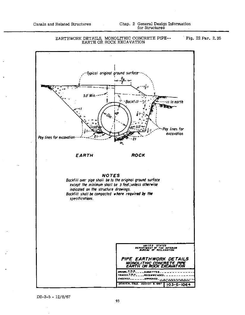
Canals and Related Structures Chap. 2 General Design Information for Structures
.
EARTHWORK DETAILS, MONOLLTHIC CONCRETE PIPE-- EARTH OR ROCK EXCAVATION
Fig. 22 Par. 2.35
I ,--Typical origin01 ground surface---. ‘.
EARTH ROCK
NOTES Backfill over pipe shall be to the oriqinol ground surface
except the minimum shall be 3 feet;un/ess otherwise indicated on the structure drawings.
Backfill shall be compacted where required &y the specifications.
I PIPE EARTH WORK DE TAILS MONOLI THlC CVNCRE TE UPE: EARTH m m EXAVATION
ORAWlL+~!L- --SU6MlTTEO- _ _ _- - - - - -es - TRACEO.RL”:. _ --RECOMME NOEO- _ - - - - - - - - -- CMECIEO- -____ APPROVEO-..- -------- -mm ermc, N”.L. .*&me” DENVER. COLO. AVCUST St 896? 1 10%D-1064
DS-3-5 - 12/8/67 93
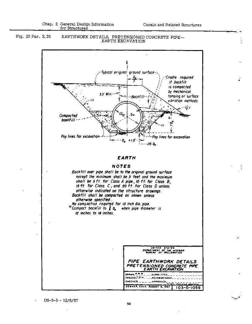
Chap. 2 General Design Information for Structures
Fig. 23 Par. 2.35
Canals and Related Structures
EARTHWORK DETAILS, PRETENSIONED CONCRETE PIPE-- EARTH EXCAVATION
.
G
I I --Typical original ground surface-.,
-‘*--.--Pay lines 4,d-LJ
for excavation cc- --a 0 z .." ,-
L - - -.05 0,
EARTH
IvOtES Bock fill over pipe shall be to the original ground surface
except the minimum shall be 3 feet and the maximum shall be 5 ft. for Class A pipe, IO ft. far Class 8, i5ft. for Class C, and 20 ft. for Class 0 unless otherwise indicated on the structure drawings.
Backfill shall be canpacted as shown unless otherwise specified .
No compaction required for IO inch dio. pipe. “Compact backfill to # 0, when pipe diometer is
12 inches to 18 inches.
OCWRwENr OF TW luTERloa 6UREAU OT REcLANArIoN
PIPE EARTH WORK DE TAILS PRE TENSIONED CONCRETE PI=
EARTH EXCAVATION DRAWL_*.“_‘?.- . _ -SUl)Nr TTED- _ _ _ _ _ _ - _ _ _ TRACELL*..L~?~ .~~~ECOYMLWOEO~ _ _ _ _ _ __ _ _ _ CnCCKLP--- -APPROVED- - - - - - - - - - - _
=rr*r. S.M.4.. rrr*sq DENYEa. COLO. AUQUSI 6. ,667 i iO3-D-105!
“ -
c
DS-3-5 - 12/8/67 94
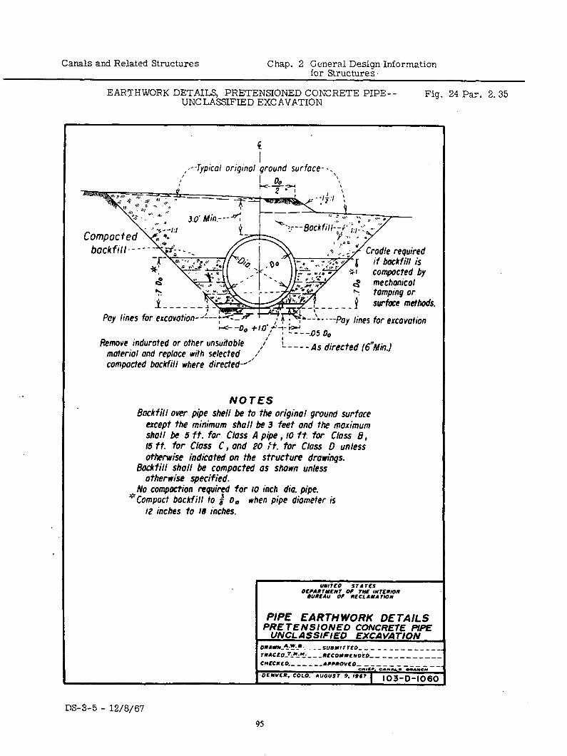
Canals and Related Structures Chap. 2 General Design Information for Structures.
EARTHWORK DETAILS, PRETENSIONED CONCRETE PIPE-- UNCLASSIFIED EXCAVATION
Fig. 24 Par. 2.35
4 I
I’ .--Typical original ground surface- -.,
I’ L-ii& ‘!\
bockfill-- -- -
surfae methods.
Remove indurated or other material and replace wit/. __.__. __ compacted backfill where directed-“.
NOlES Backfill over pbe shell be to the original ground surface
except the minimum shall be 3 feet and the maximum shall be 5 ft. far Class A pipe , IO ft. for Class 8, 15 ft. for Class C, and PO I?. far Class 0 unless otherwise indicated an the structure drowihgs.
Backfill shall be compacted as shown unless otherwise specified.
No compaction required for IO inch dia. pipe. “Compact backfill to # o. when pipe diameter is
12 inches to 18 inches.
UNI 7EO STATES DECAR74lEN7 OF TNE INTERIOR
9UREAU OF RECLANA7lON
PIPE EARTHWORK DETAILS PRETENSIONED CONCRETE PIPE
UNCLASSIFIED EXCAVATION ORANN~A%?~D~. . _ _ SU9NITTEO- -- _-_----_--. 7RACEO-r~=!~~i: - -RECONUENDkO- _ _ - _ - _ - _ - -_ CHECKED.- __ _ ,-APPROVE0 ------------_
C”*aC. CIolY. . ..“O” -DENVER. COLO. AUGUST 9. ,967 1 103-0-1060
DS-3-5 - 12/8/67
95
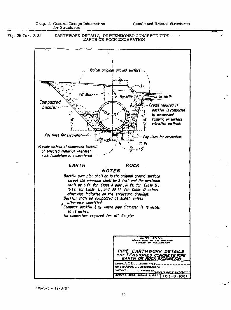
Chap. 2 General Design Information for Structures
Canals and Related Structures
- Fig. 25 Par. 2.35 EARTHWORK DETAILS, PRETENSIONED CONCRETE PIPE--
EARTH OR ROCK EXCAVATION
I I - - Typical original ground surface -., <’ I \
earth
Poy lines
Provide cushion of compacted bockfill of selected moteriol wherever
& i”;“‘:--* ‘0
G
- Crodllc required if bockfill is aqnxt&
Du.. .‘,C -a ** f 1’ .* ym *’ ty mechonicol * r;.w B tomping or swfoce
vibration methods.
lines for excovotion
rock foundotion is encountered -----**-
EARTH ROCK NO TPS
Backfill over pipe shall be to the’ original ground surface except the minimum shall be 3 feet ond the maximum shall be f ft: for Gloss A pipe , 14 f t for Gloss B , 15 ft. for Gloss C, ond 2yI ft. for Gloss D unless otherwise indicuted on the structure dmwings.
Bockfill shall be compacted OS shown unless * other wise specified.
Compact bock fill 3 Do where pipe diometer is 12 inches to 18 inches.
No compaction required for ID” dio. pipe.
PIPE EARTH WORK DE TAILS PRE TENSIONED W#ETE PIPE
L EARTH OR /K)cK EXCAWW’ION OrrtvN~~~w~~~ ---__- SUm*c~~EO~~---~---~~. TOAC E o-‘?2!! _ - nECOYuE*OEo- - - - - - - - - - CllECliEO - _ - -.,- APPROVEO- _ - _ _ __ _. - _ _ _
e***,. S.“ai., m DENVER. COLO. AUGUST 9. I94I 1 103-0-1061
DS-3-5 - 12/8/6’7 96
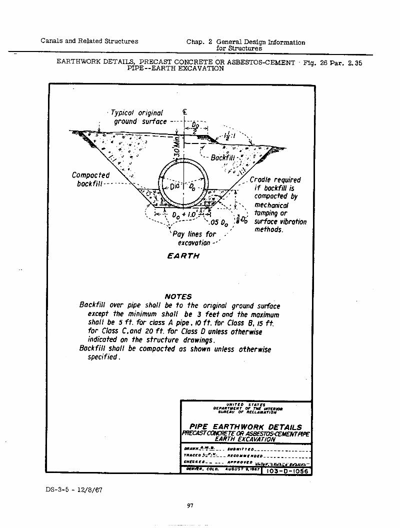
Canals and Related Structures Chap. 2 General Design Information for Structures
EARTHWORK DETAILS, PRECAST CONCRETE OR ASBESTOS-CEMENT Fig. 26 Par. 2.35 PIPE--EARTH EXCAVATION
. .
. Typical oriqinal F
bockfill--- ----
excavation -a’
EARTH
NOTES Backfill over pipe shall be to the oriqinal ground surface
except the minimum shall be 3 feet and the maximum shall be 5 ft. for class A pipe , 10 ft. for Class 8, 15 ft. for Class C. and 20 ft. for Class D unless otherwise indicated on the structure drawings.
Backfill shall be compacted OS shown unless otherwise specified.
DS-3-5 - 12/8/67
97
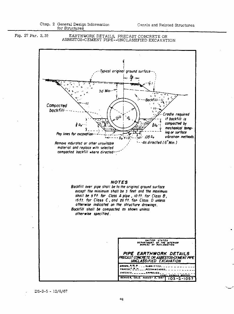
Chap. 2 General Design Information for Structures
Canals and Related Structures
Fig. 27 Par. 2.35 EARTHWORK DETAILS, PRECAST CONCRETE OR ASBESTOS-CEMENT PIPE--UNCLASSIFIED EXCAVATION
.-
, ,---TyPICa/ Oriqind ground surface--.>
Pay hnes for excavation--~---,--- - f I.O,J- - +- .05 Do
Remove indurated or other unsuitable /’ L - -As directed (6”Min.j moteriol and replace with selected ,,” compacted backfill where directed--“*
NOTES Backfill over pipe shall be to the oriqinol ground surface
except the minimum shall be 3’ feet and the maximum shall be 5 f t for Class A pipe , 10 ft. for Class 6, 15 ft. for Class C , ond 20 ft. for Class 0 unless otherwise indicated on the structure drowinqs.
Backfill stwll be compacted as shown unless otherwise specified.
PIPE EARTHWORK DETAILS R?Ea5TcmKxEl-E m A52xsTll;rs-c~Nr#
ma ASsmD EXCA V. ri0N oumvu-‘~x~~~. - - Su#YITrEo~ - _ - _ _ _ _ __ _ _ _. T~ACEO-7.-!~ se, -___ ~EC0YYEW0C0~ - - _ - - _ ____ CUECKE 0 --__ --APPmovco- - .- _ - - ._ __ _ _ s*lKc. C.I.LB “.*cr OCYVER. COCO. AUGUSI 9. IS67 1 103 -0 _, 057
.
: . I -i
DS-3-5 - 12/8/67
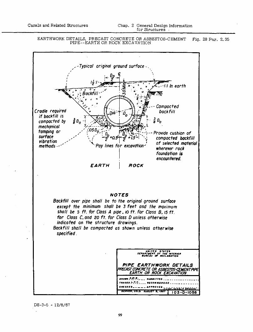
Canals and Related Structures Chap. 2 General Design Information for Structures
EARTHWORK DETAILS, PRECAST CONCRETE OR ASBESTOS-CEMENT PIPE--EARTH OR ROCK EXCAVATION
Fig. 28 Par. 2.35
‘rod/e required if bockfill is compoc ted by mechonicol tompinq or surface vibrotion methods -e*/’
, . c Typical originol ground surface - . ,
L - -I:/ In ear jh
‘-Pay lines excovdfion’ I
- Compacted bock fill
Provide cushion of compoc ted bock fill of selected moteriol wherever rock foundation is encountered.
EARTH I ROCK
NOTES BockfW over pipe shall be to the original ground surface
except the minimum shall be 3 feet and the moximum shall be 5 ft. fir Class A pipe, IO ft. for Class 8, 15 ft. for Closs C, ond 20 ft. for Gloss D unless otherwise indicated on the structure drowings.
Bockfill sho11 be compacted OS shown unless otherwise specified.
un1rl?o srarcs DcPAarNcnr OF rhlc IIYrfaloOR
l UUEAU OF m?cLAm4rIo*
PIPE EARTH WORK DETAILS FW0ISTQJ%‘KTE OR ASBESTDS-CEMWTTPI
EARTH OR ROCK EXCAVATION o*Awaf~~?!~-,~ SUomlrrCO ._- -- ---__ - _____ reAcro~k~CIL~~~ wECO**CaoIo ________ ____
DS-3-5 - 12/8/67
99
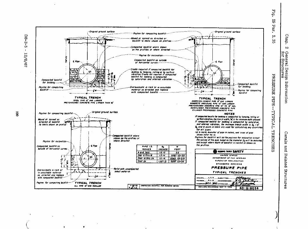
:~orlgpmal ground swracr :. -__ .._.._. _--.---.., -Se’--.Paylinr far campactmg backf,lt.--‘.
____.._ ___.---.----.A-- . . . . . ,... -0Wnol ground surface .. : I
------ktamd Or spread a, drrrcted 0~ ..rJ”‘,--+ --p-j - - -_____
bockfttl ta bouts shawl an pror,,,,....--.---“’
-“‘.------------Compochd backfill where shown On thr Profile, OT where drrcctrd-----
Compacted backfrn an outs& of har~rantal CUT”,,..---~-.~-----....
.---CrUdIt rrqwred rf campactrd backfill far MWv by hwmg. mltrng Q b swfacr vrbdron Cradle not required J / campa,t#d back frtt for brddq ,I COmPactrd by ,aturat#an and mternal ribratton-. ._
Payline for campactmg bock/ill---.-. .._..._ -..--
___._._ -... . ..--.Orwrrcovate m rack Or cn unsu11 material a, dwectrd and replay. rrt* cnmsnc,rd *nr,,i,, . . . .._ _-.. ._...--.---~‘--~-- - --.--jr -__.. -(
Paytinc far compacting
TYPICAL TRENGtl SrEEL C1CE w MO LAWE”
METENk,OuEO CO”O”ErE PlPE L.101” ntA” y’
backfttl - . . *. . . .
~Origmal qround rur face
kbund or spread a, +rrcbn vibration. the tren:h wdt~~i$i~ Me minimum ndth allowed If comgacted ballill fw beWmg i, compacted by saturat~o1:
and tntunat vrbratron. the mmi%wn trench wdth II & *I#? 4 and w qiven in table arc used far catculotrng pay quantrtir
for at1 YIPCI. I I.11 i, inri6 drometer of pipe m mchrs. and ,wc, of p,pt : i -C-ted backftll wkwr shown refer to I 0.
shown gn thr prafiibr Or Paylmrs far bockfrll w/t be thrpoylinrs for e~ccvoho~ erce~pt
Fayl/nC far eIcavatlan.-.. I ’ whtre directed the VO~MW Of thr DlPt bawd On the lometer 00 rrll be dedvctcd
. . . ‘hmnrrr,,” tlnr,,,,, n.9
/ 1. . i ..c PIa6 : and e~t~t wh8re d&h of backhll I, lrmrtrd OS shorn an
the profll8s - . . . r _-,_- _-__. . . . 1 . .
wt,rde of haruantal curws.,,
IvrrcIcavar- .- ---. -- rc’“rOcn Or
1. I” un,urtable materrot w ,‘trected and replace with compacted backftll - - *’
I PRESSURE PIPE TYPICAL TRENCHES
‘aylinr fr campacting Inckfrll-*-e’e’ iYPlCAL WENCH ALL PM WAN0 SMALLER
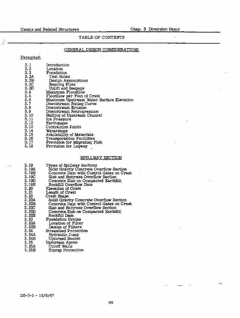
Canals and Related Structures Chap. 3 Diversion Dams
TABLE OF CONTENTS
GENERAL DESIGN CONSIDERATIONS
Parasranh
z-i 313 3.3A 3.3B
%
::‘5
E
E 3: 10 3.11 3.12 3.13 3.14 3.15 3.16 3.17 3.18
3.19 3.19A 3.19B 3.19C 3.19D 3.19E 3.20 3.21 3.22 3.22A 3.22B 3.22C
Eifi 3: 23 3.23A
:* t? 3: 24A 3.24B 3.25 3.25A 3.25B
Introduction Location Foundation
Test Holes Design Assumptions Bearing Piles Uplift and Seepage
Maximum Floodflow Floodflow per Foot of Crest Maximum Upstream Water Surface Elevation Downstream Rating Curve Downstream Erosion Downstream Retrogression Shifting of Upstream Channel Ice Pressure Earthquake Contraction Joints Waterstops Availability of Materials Transportation Facilities Provision for Migrating Fish Provision for Logway -
SPILLWAY SECTION
Types of Spillway Sections Solid Gravity Concrete Overflow Section Concrete Dam with Control Gates on Crest Slab and Buttress Overflow Section Concrete Slab on Compacted Earthfill Rockfill Overflow Dam
Elevation of Crest Length of Crest Crest Shape
Solid Gravity Concrete Overflow Section Concrete Dam with Control Gates on Crest Slab and Buttress Overflow Section Concrete Slab on Compacted EarthfiH Rockfill Dam
Foundation Drains Location of Filter Design of Filters
Streambed Protection Hydraulic Jump Upturned Bucket
Upstream Apron cutoff walls Riprap Protection
- . -
DS-3-5 - 12/8/67
101
___. _ .
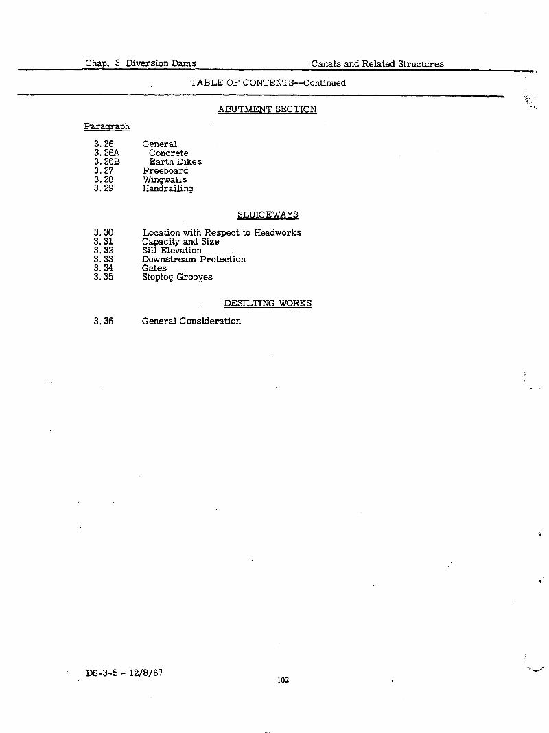
Chap. 3 Diversion Dams Canals and Related Structures
TABLE OF CONTENTS--Continued
ABUTMENT SECTION :... ,
. .
Parauraph
3.26 General 3.26A Concrete 3.26B Earth Dikes 3.27 Freeboard 3.28 3.29
wingwalls Handrailing
3.30 Location with Respect to Headworks 3.31 3.32
Capacity and Size Sill Elevation
3.33 Downstream Protection 3.34 Gates 3.35 Stoplog Grooves
3.36
SLUICEWAYS
DESILTING WORKS
General Consideration
DS-3-5 - 12/8/67
i
,
-:.-.rr
102
Canals and Related Structures Chap. 3 Diversion Dams
TABLE OF CONTENTS--Continued
LIST OF FIGURES
Figure Number
1
2
3
4
5
6
7
a 9
Dunlap Diversion Dam&-General Plan-Sections
Woodston Diversion Dam-- General Plan and Sections
Knight Diversion Dam--General Plan and Sections--(Sheet 1 of 2)
Knight Diversion Dam--General Plan and Sections--(Sheet 2 of 2)
Putah Diversion Dam--General Plan, Elevation, and Sections
Putah Diversion Dam--General Sections
Duchesne Feeder Canal Diversion Dam--General Plan, Elevation, Sections
Robles Diversion Dam--General Plan
Robles Diversion Dam--Elevation and Sections
Paragraph Drawing Reference Number
3.19A 278-D- 193
3.19A 468-D- 259
3.19A 66-D- 159
3.19A 66-D- 160
3.19B 413-D-412
3.19B 413-D-413
3.19D 209-D-44 1
3.19E 767-D-231
3.19E 767-D-232
DS-3-5 - 12/a/67 103
Canals and Related Structures Chap. 3 Diversion Dams
.1
.2
.3
3.1
GENERAL DESIGN CONSIDERATIONS
To make water flowing in a stream available for i.rrigation use, it must be diverted by means of a diversion dam and headworks, a diversion headworks
INTRODUCTION
alone, or a pumping plant. Elements of a general nature to be considered in the design of diversion dams and headworks are discussed in this chapter. The design of each diversion dam involves the solution of a-different set of problems. The objectives of this chapter will therefore be to point out the various features to be considered in the design and to establish broad limits of control. In the structure drawings selected for illustration, there may be instances in which current design practices differ in some respects from those illustrated.
The approximate location of a diversion dam is usually established by the LOCATION requirements of the project plan. These requirements are not considered in this chapter. However, it should be noted that although the general loca- tion of a structure is fixed by other than design considerations, the precise location may usually be shifted within certain limits, so that advantage can be taken of natural features of the site to provide for economy of construction.
It may be required to place a diversion dam on almost any type of foundation FOUNDATION material. Few sites for diversion dams permit construction on a rock foun- dation, since bedrock is usually at such depth that its use as a foundation is impracticable. Because most diversion dams are founded on pervious or semipervious riverbed materials, only these will be discussed here. Con- siderations in the design of diversion dams founded on rock are similar to those in the design of gravity dams discussed in Chapter 2, Gravity Dams, of Design Standards No. 2, Concrete Dams. The following items concerning foundations require consideration in the design:
A.
‘B.
C.
D.
Test borings or test pits are necessary for investigation of the character of the material upon which the dam is to be founded.
Test Holes
In the design of a dam, the allowable bearing pressure, shearing strength, and sliding factor must be selected either upon the basis of past experience, or from the results of tests of the foundation material in place or tests of samples taken from the test holes or test pits.
Design Assumptions
Bearing piles are seldom used as supports for diversion dams, although they may be provided where a dam must be built on an unstable founda- tion material. This type of construction affords very little protection against undermining of the structure and has been a contributing factor in the failure of several dams. Imperial Dam on the Colorado River is an example of a diversion dam built on piles. The design of Imperial Dam is discussed in the Boulder Canyon Project Final Reports, Part IV, Design and Construction, Bulletin 6, Imperial Dam and Desilting Works.
Bearing Piles
The installation of cutoff walls, aprons, filters, and drains is discussed subsequently in this chapter. The purpose of these features is twofold: to control the amount of seepage under the dam, and to limit the inten- sity of the uplift so that the stability of the structure will not be threat- ened. Several factors such as the head on the dam, permeability of the foundation, length of upstream and downstream aprons, depth and tight- ness of cutoff, and effectiveness of drains enter into consideration of underseepage and uplift.
Uplift and
Seepage
The magnitude of the uplift forces under the structure and the amount of underseepage for a given coefficient of permeability can be obtained from a flow net. A theoretical discussion of the flow net and tables of repre- sentative coefficients of permeability may be found in Engineering Mono- graph No. 8, entitled “Theory and Problems of Water Percolation, I1 by
DS-3-5 - 12/8/67
10s
Chap. 3 Diversion Dams Canals and Related Structures
3.4
GENERAL DESIGN CONSIDERATIONS--Continued
C. N. Zangar. Most standard, texts on hydraulic structures, including “Engineering for Dams, ” by Creager, Justin and Hinds, show typical examples of flow nets.
The flow net itself may be constructed either by sketching or by electric tray analogy. For preliminary design it is sufficient to sketch the flow net, provided the foundation material is homogeneous or reasonably close to it. Lack of homogeneity need not rule out sketching the flow net, but the more complex the foundation the less reliable the results since an assumption of homogeneity is basic.
For all final designs and for preliminary designs on complex foundations, a flow net should not be attempted by sketching. Electric analogy is the best method for any foundation, and complex foundations can be simu- lated by varying the depth of the electrolyte in various regions in accord- ance with the permeability of the material. The electric analogy is an accurate and inexpensive method of obtaining a flow net which leads to estimating uplift intensities under the dam and quantity of underseepage.
It should be noted that, for all homogeneous foundations (or those assumed homogeneous), the shape of the flow net does not depend on the perme- ability of the foundation. The permeability coefficient is a factor in the computation for underseepage but not for uplift.
In considering the safety of a concrete dam on a pervious foundation, many engineers have found that Lane’s weighted-creep theory is helpful. This theory is fully explained in the ASCE Transactions, Volume 100, 1935, under the title of “Security From Underseepage. ” Mr. Lane tested his theory by analyzing more than 200 existing dams, both failures and nonfailures. This theory gives another method of computing uplift under the dam, and it enables the designer to judge the safety of the structure by the computation of the weighted-creep-head ratio.
Khosla’s method of independent variables,. presented in the journal of the Central Board of Irrigation, India, September 1936, is another theory that is n.seful in estimating the magnitude and distribution of uplift pres- sures under the dam.
The possibility of piping should always be investigated where a concrete dam is constructed on a pervious foundation. The most critical area is at the downstream toe of the dam or at the bottom of the downstream cutoff. At any depth the submerged weight of the soil above the point in question must exceed the pressure potential in the soil in order to have some margin of safety against piping. Safety against piping may be increased by adding riprap over the questionable area or by providing a filtered weep or drain to relieve the pressure potential, or both.
MAXIMUM FLOOD-
FLOW
.4 Diversion dams are designed to safely pass floodflows of 50- or loo-year probable frequency. The selection of the design flood is governed by economic considerations. The responsibilities and procedures for determination of maximum floodflows for diversion dams are given in the Reclamation Instruc- tions, Series 110, Planning, and 130, Design.
FLOOD- .5 For the design of dams located on a sandy foundation, the flood discharge per FLOW PER linear foot of cverrlow crest is usually limited because of the cost of protect- .FOOT OF ing against downstream erosion. The discharge per linear foot of dam may
CREST also be limited by the allowable upstream water surface elevation.
DS-3-5 - 12/8/67 106
.6
.7
.8
.9
.10
. 11
.12
.13
.I4
3.6
Canals and Related Structures Chap. 3 Diversion Dams
GENERAL DESIGN CONSIDERATIONS--Continued
The maximum allowable upstream water surface elevation is often depend- MAXIMUM UP-
STREAM WATER ent on the elevation of railroads, highways, bridges, buildings, and other SURFACE properties. ELEVATION
The rating curve of the natural stream below the dam is necessary to per- DOWNSTREAM mit proper provision in the design for energy dissipation. Information in RATING regard to this downstream water surface elevation may also be necessary CURVE to determine the flood discharge in cases of submerged overpour. For a discussion pertaining to effect of submergence on coefficient of discharge, see Hydraulic Laboratory Report No. 182, entitled “Studies of Flow Charac- teristics, Discharge and Pressures Relative to Submerged Dams, ‘I by J. N. Bradley.
Erosion of the streambed downstream from the dam should be prevented by DOWNSTREAM the proper design for the dissipation of energy of the overpour water and EROSION by provision for riprap or rock paving on the banks and bottom of the stream- bed. A cutoff wall is usually’provided at the downstream end of the structure as additional protection against erosion.
Retrogression of a sandy streambed downstream from a diversion dam DOWNSTREAM should be expected, particularly where an upstream storage reservoir will intercept and retain the natural sand load carried by the stream. In REYE:ES- some cases, protection against this lowering of the streambed and the resulting lowering of the tailwater elevation may become very difficult and costly.
Where a diversion dam is to be built across a stream meandering down a flat valley floor, there may be danger of the stream shifting to another location during a flood and thus bypassing the dam completely. Consider- able riverbank protection may be necessary to guard against this contin- gency, or a long dike may be required across the valley floor.
suwL&F CHANNEL
In cold climates, ice pressure may become a very important factor in the ICE design of diversion dams. The ice pressure constitutes a relatively larger PRESSURE force on small dams than on large ones. Final selection of the design value should be made after consideration of the importance of the effects of re- strain\ temperature, and snow conditions. individual locality.
These factors will vary with the For a more complete discussion of ice pressures, see
“Thrust Exerted by Expanding Ice Sheet, ” by Edwin Rose, ASCE Transactions, Volume 112, page 871, and ~Experimental Investigations by the Bureau of Reclamation, ‘I by G. E. Monfore, ASCE Transactions, Volume 119, page 26.
Forces due to earthquakes acting on the structure should be considered in the design of diversion dams. The intensity of the earthquake force to be used in the design will depend on the area where the structure is to be built.. Engineering Monograph No. 11, entitled “Hydrodynamic Pressures on Dams Due to Horizontal Earthquake Shock” gives the hydrodynamic pressures on dams due to horizontal earthquake effects.
EARTH- QUAKE
Contraction joints in diversion dam structures require considerable study. CONTRACTION They must be watertight in spite of differential settlement and must provide JOINTS for contraction and expansion of the concrete to prevent cracking. See Chapter 2, General Design Information for Structures, for further informa- tion on contraction joints.
Rubber waterstops have been used successfully for many years to seal con- WATERSTOPS traction joints where movement is probable. Recent specifications permit use of plastic waterstops as an alternative to rubber.
DS-3-5 - 12/8/67
107
3. 15
Chap. 3 Diversion Dams Canals and Related Structures
GENERAL DESIGN CONSIDERATIONS--Continued
AVAIL- ABILITY
ISE- RIALS
TRANSPCR- TATION
FACILITIES
PROVI- SION FOR MIGRA-
TORY FISH
PROVI- SION FOR LOGWAY
TYPES
SPILoL”WAY SECTIONS
Solid Gravity
Concrete Overflow
Set tion
Concrete Damwith Control Gates on
Crest
Slab and C. The slab and buttress overflow section is constructed of reinforced con- Buttress Overflow
Crete and usually consists of a sloping upstream slab and an ogee-shaped
Set tion downstream face supported on a horizontal foundation slab by equally spaced concrete buttresses. An .example of a slab and buttress diversion
.15
.16
.17
38
. 19
The economic design of a diversion dam may be,considerably influenced by the availability and cost of certain construction materials at the particular site. Such materials are rock for riprap; sand and gravel, or crushed rock for concrete aggregates, roads, blankets, and filters; and earth for com- pacted fills.
The design of a diversion dam may be influenced by the proximity of railroads and highways which affect the cost of materials to be used.
Some diversion dams are located on streams which support large numbers of migratory and other types of fish, which may be important both commer- cially and recreationally. Fish screens and fish ladders must be provided in these cases to prevent the entry of fish into the canals and to permit the natural migration of fish to and from their spawning areas.
In some cases, it may be necessary to provide logways for the passage of logs being floated to the sawmills.
SPILLWAY SECTION
In selecting the type of spillway section to be used in the design of a diversion dam for a particular site, the following controlling factors are to be consid- ered: character and strength of foundation; availability of construction mate- rial; necessity for a controlled crest- and cost. The types of spillway sections most generally used in the design of diversion dams are listed below and dis- cussed in the following paragraphs:
Concrete ogee solid gravity Concrete dam with control gates on crest ’ Concrete ogee slab and buttress Concrete slab on compacted earthfill Rockfill
A. The usual form of the solid gravity concrete overflow section has a verti- cal upstream face and a rounded crest with an ogee face downstream. This type is the one most commonly used where no control of the up- stream water surface during floodflows is needed; it is most frequently used on a rock foundation. In case the dam is to be built on a sand or gravel foundation, the extent to which this type can be used will depend on the supporting power of the foundation material. Examples of solid gravity diversion dams are shown in Figures 1, 2, 3, and 4.
B. The concrete dam with crest control gates is used where control of the upstream water surface during floodflows is necessary. This control is required where the great value of property and improvements affected by backwater prohibits the use of an uncontrolled crest. The most dis- tinguishing feature of the various gated-crest dams is the type of gates used. The type of gate to be selected depends principally on the condi- tions under which the gates must operate. Problems involved in select- ing the type of gates to be used for a particular dam and a given set of operating conditions require special study. An example of a concrete dam with control gates on the crest is the Putah Diversion Dam shown in Figures 5 and 6.
DS-3-5 - 12/a/6?
108
Canals and Related Structures Chap. 3 Diversion Dams
. .
SPILLWAY SECTION--Continued
dam is the Imperial Dam on the Colorado River. This type of dam, being much lighter per square foot of area covered than the solid gravity type, is more suitable to foundations with low bearing strength. The difference in first cost between a slab and buttress dam and a solid gravity dam depends on local conditions and the availability of con&r&- tion material. The slab and buttress type of construction is seldom used for dams of heights less than 20 feet.
D. The concrete slab on a compacted earthfill type of overflow section may be used economically where the height is 5 feet or less. It consists of reinforced concrete slabs extending upstream and downstream from the crest which rests on a sheet-piling cutoff wall. The downstream slab is constructed on a filter and is weeped to prevent uplift. The Duchesne Diversion Dam constructed across the Duchesne River (Figure 7) is of this type.
E. In locations where rock is plentiful and economical to obtain! the over- flow section may consist of a rockfill with either a sheet-piling or con- crete diaphragm to form the crest and cutoff. The rockfill is placed on top of a filter to prevent the overflowing water from displacing the foundation material. Rock for the rockfill is angular in shape and derrick-placed in such a manner that the rock will resist displacement by a keying or interlocking effect. This interlocking is particularly important in the downstream portion of the section. The minimum size of rock and the slopes are dependent on the amount of overpour per linear foot of crest and the height of dam. Ordinarily, the downstream slope is flatter and the rock is of, larger size than in the upstream por- tion of the dam because of the greater likelihood of displacement. This type of dam is often economical to construct; but it is limited in height to 5 feet maximum between the upstream and downstream water surfaces and to a capacity of about 30 cfs per foot of width, because of question- able stability against very high velocity flows over the downstream rock- fill. Additional percolation path to that furnished by the diaphragm is sometimes provided by an impervious blanket extending upstream under the gravel filter and rockfill. This blanket should be carefully placed and well protected, and should be thick enough to eliminate any danger of a fracture. The rockfill design is not recommended for use on easily erodible foundations. An example of a rockfill design is Robles Diver- sion Dam shown in Figures 8 and 9.
.20 The purpose of a diversion weir is to raise or control the water surface in the river so that the desired flow may be diverted into the canal and yet function properly as a spillway for floodflows. The water surface elevation in the pool formed by the diversion dam is determined by the head required for the canal when flowing at full capacity. When the entire flow of the river at low flows may be diverted, the uncontrolled crest or the top of the gates on a gated crest usually has about 0.5-foot freeboard above the water surface required to supply the canal. This freeboard is necessary to prevent water from being wasted over the dam by wave action. When the minimum flow in the river exceeds diversion requirements, it is necessary only that the mini- mum low water level of the rive* upstream of the dam be high enough above the canal water surface to provide the necessary head for the canal. The elevation of a gated crest is usually determined from an economic study of various size gates and by the maximum allowable upstream water surface during floods.
.21 There are many factors, depending on the physical features of a given site, to be considered in determining the length of the overflow weir. Because of the many factors involved, no fixed rule can be made for determining
3.19D
Slab and Buttress Overflow
Section (Cont’d. 1
Concrete Slab on
Compacted Earthfill
Rockfill Overflow
Section
ELEVATION OF CREST
LENGTH
&i&T
DS-3-5 - 12/8/67
109
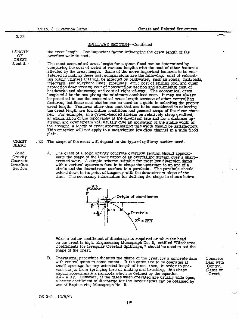
3.22 --
--.
SPILLWAY SECTION--Continued
the crest length. One important factor influencing the crest length of the overflow weir is cost.
The most economical crest length for a given flood can be determined by comparing the cost of weirs of various lengths with the cost of other features affected by the crest length. Some of the more important features to be con- sidered in making these cost comparisons are the following: cost of relocat- ing public utilities that will be affected by backwater, such as roads, railroads, telegraph, and telephone lines, pipelines, etc.; cost of stilling pool and other protection downstream; cost of nonoverflow section and abutments; cost of headworks and sluiceway; and cost of right-of-way. The economical crest length will be the one giving the minimum combined cost. It may not always be practical to use the economical crest length because of other controlling features, but these cost studies.can be used as a guide in selecting the proper crest length. Features other than cost that are to be considered in selecting the crest length are foundation conditions and general shape of the river chan- nel. For example, in a gravel-bedded stream on relatively steep gradient, an examination of the topography at the diversion site and for a distance up- stream and downstream will usually give an indication of the stable width of the stream: a length of crest approximating this width should be satisfactory. This criterion will not apply to a meandering low-flow channel in a wide flood pldI-l.
.22 The shape of the crest will depend on the type of spillway section used.
LENGTH
C:&T (Cont’d. 1
CREST SHAPE
Solid Gravity
Concrete Overflow
Section
A. The crest of a solid gravity concrete overflow section should approxi- mate the shape of the lower nappe of an overfalling stream over a sharp- crested weir. A simple scheme suitable for most low diversion dams with a vertical upstream face is to shape the upstream to an arc of a circle and the downstream surface to a parabola. The parabola should extend down to its point of tangency with the downstream slope of the dam. The necessary information for defining the shape is shown below.
w. 5. - ---- *c H
J I ,-Origin of coordinates
-&+Lr--~
‘I@’ x *s# ,
@\
I-- Parabola
I x2 =2EY
When a better coefficient of discharge is required or when the head on the crest is high, Engineering Monograph No. 9, entitled “Discharge Coefficients for Irreguiar Overfall Spillways, ” should be used to set the shape of the crest.
B. Operational procedure dictates the shape of the crest for a concrete dam Concrete with control gates to some extent. If the gates are to be operated at Dam with small openings for any extended length of time, then, in order to pre- Control vent the jet from springing free or making and breaking, this shape .Gates on should a.pproximate a parabola which is defined by the equation X2 = 4 HY.
Crest However, if the gates when operated are usually wide open,
a better coefficient of discharge for the larger flows can be obtained by use of Engineering Monograph No. 9.
--. DS-3-5 - 12/8/6’7
110
Canals and Related Structures Chap. 3 Diversion Dams
SPILLWAY SECTION--Continued
C. . The downstream surface of the crest for a slab and buttress overflow section should be the same as for the solid gravity section if ungated, or the same as for a concrete dam with control gates if gated. The upstream surface usually has a radius at the crest, but the upstream face itself is usually sloping instead of vertical as in the previous cases.
D. The crest for a concrete slab on compacted earthfill is a broad-crested weir with flat slopes either way from the crest.
E. The crest for a rockfill overflow section is usually a cutoff wall of concrete, wood or steel sheet piling with a flat rock slope each way from the cutoff wall. The upstream slope may be somewhat steeper than the downstream slope because of the water action.
.23 Foundation drains for diversion dams generally consist of a main filter located under the downstream toe of the dam. Outlets from the filter drain consist of pipes extending from the filter to the top surface of the apron or to the downstream face of the dam. It is preferable for these outlet pipes to be sloped in a downstream direction so the water flowing over the dam will produce an ejector effect to increase the action of the filter drain. If conditions are such that a deep stilling pool is required where silt-laden .water is expected to stand for extended periods of time, the outlet pipes may become clogged with sediment. In this case consideration should be given to placing flap valves on the outlet ends of the pipes, or some other measures should be provided to prevent clogging.
A. The location of the filter is a matter of cost. If the filter is located near the downstream toe of the overflow section, additional upstream apron and cutoff wall will be required to furnish the necessary path of percolation. On the other hand, if the filter is located at the down- stream edge of the apron, the apron can be considered as contributing to the percolation path and the length of upstream apron can be reduced. However, with the filter in the latter location, the amount of uplift would be increased, thus requiring more concrete in the dam and apron for stability. Generally, a filter near the downstream toe of the’ overflow section of the dam will be at the most economical location.
B. The gradation of the foundation material determines the type of filter to be used. filters.
The two types of filters commonly used are zoned and graded The criteria for designing protective filters is described in
Earth Material Laboratory Report No. EM-425.
.24 Protection of the streambed downstream from the overflow weir is furnished by a downstream apron or an upturned bucket, both supplemented with heavy riprap or articulated concrete blocks. The upturned bucket should be used only in streambeds composed of boulders and coarse gravel, or other mate- rial not easily eroded. The riprap or articulated block protection should be placed on a blanket of gravel or rock spalls to prevent the streambed mate- rial from being drawn up through the interstices in the protection. In the case of fine streambed material, it may be necessary to construct this blanket as a filter using a layer of sand as the lower course with a layer of gravel on top.
A. One of the most effective means of dissipating the kinetic energy of the water discharging over a weir is by means of a hydraulic jump on a con- crete apron. The use of baffle blocks can improve the jump and reduce
3.22C
Slab and Buttress Overflow
Section
Concrete Slab on Compacted
Earthfill
Rockfill Overflow
Set tion
FOUNDATION DRAINS
Location of Filter
Filters
STREAMBED PROTECTION
Hydraulic Jump
DS-3-5 - 12/8/67
Chap. 3 Diversion Dams Canals and Related Structures
3.24B
Hydraulic Jump
(Cont’d. 1
Upturned Bucket
UPSTREAM APRON
. .
Cutoff walls
Riprap Protection
.25
SPILLWAY SECTION--Continued
the required tailwater depth and length of jump. Engineering Monograph No. 25 gives design criteria. for stilling basins and the arrangement of baf- fle blocks. Unless a model study shows otherwise, the minimum length of apron should be four times the depth of the hydraulic jump, or 4d, .,
On streams where retrogression can be expected, it is very important to make an estimate of its amount so that the tailwater rating curve can be adjusted to represent future conditions. Otherwise, construction which provides a perfect jump with present tailwater elevations will become worthless because of the future lowering of the tailwater due to retrogression of the river channel.
B. Where high%ailwater is available, an upturned bucket may be used for energy dissipation and may be more economical than a concrete apron because of the smaller amount of concrete needed for construction. The upturned bucket shouldnot be used where riverbed material will erode easily and where there is a possibility that degradation of the streambed will lower the tailwater below the design minimum. Engineering Mono- graph No. 25 gives the design criteria for setting the bucket elevation and dimensions. Woodston Diversion Dam (see Figure 2) is an example of a diversion dam with an upturned bucket to dissipate the energy.
An upstream concrete apron has been found very advantageous for diversion dams on pervious sand or gravel foundations. In addition to providing an increased length of path of percolation, the apron provides space for the several rows of sheet piling sometines required. The upstream apron, or a part thereof, is often tied by steel reinforcement to the dam, thus develop- ing a substantial increase in the sliding resistance of the whole structure. Still another purpose of the upstream apron is to prevent erosion adjacent to the dam during periods of floodflow. A minimum length of approximately three times the height of the overflow section will give good proportions.
A. An upstream cutoff wall or walls under the apron usually furnish a large portion of the required path of percolation under a diversion.dam. These cutoff walls may be formed by steel, timber, or concrete sheet piling; by mixed-in-place cement-bound curtains; or by concrete walls. The cutoffs should extend to impervious material wherever practicable. If foundations contain large boulders which would interfere with the driving of sheet piling, trenches for the cutoffs can be excavated. These trenches should be excavated on slopes such that shoring of the excavation will not be required. The cutoff can be constructed in the trench backfilled with impervious material, or if sheet piling is used the trench can be back- filled first and the sheet piling driven into the backfill. Several factors will determine the type of cutoff wall used. Among these factors are the initial cost of construction, cost of maintenance, water tightness desired, type of foundation material, etc. Cutoffs should be spaced no closer than about three times the depth of the deepest cutoff.
B. Often it is necessary to furnish some protection against erosion of the streambed and banks upstream from the apron and wing-walls. is the most commonly used material for this purpose.
Riprap Since the maxi-
mum velocities upstream from the dam are lower than the original river velocities before the dam was built, the riprap usually need not be very heavy. In fact, a coarse gravel blanket will often serve in lieu of riprap.
.
’ DS-3-5 - 12/8/67 112
Canals and Related Structures Chap. 3 Diversion Dams
.26
.27
.2a
.29 . .
.30
.31
.32
3.26
ABUTMENT SECTION
Where it is not economical or desirable from desi.gn considerations to extend GENERAL the spillway section across the entire river channel, the length which is not closed by a spillway section is closed by a nonoverflow or abutment section. Abutment sections are of concrete tied into the river banks or into earth dikes.
A. Concrete abutment sections are designed as low concrete dams. Pro- Concrete tection at the banks is provided by cutoff walls and wingwalls.
B. Earth dikes are designed on the same principles as low earth dams. Earth The top width should be sufficient for the travel of trucks or cars for Dikes inspection, maintenance, and access to the spillway se&don and head- works. The upstream slopes must be protected against erosion, wave action, and the destructive work of rodents. This protection can be provided by riprap, grass, willows, or brush mats. The downstream slope is not usually protected unless the floodwater rises to considerable height on the embankment.
Freeboard must be provided to prevent overtopping by wave action and for an additional safety factor. The minimum freeboard should be 2 feet.
Wingwalls are provided to join the spillway section or the headworks to the earth dike or banks. They prevent erosion of the banks and provide resist- ante to percolation around the end of the spillway section or headworks. They can be vertical, warped, or sloped, depending on the general design and hydraulic requirements. The walls are designed for the earth and water- loads to which they will be subjected.
FREE- BOARD
z!E&
Handrailing is provided to prevent injury to the public or operators. The three common types of railing are pipe, concrete, and wood. Additional information concerning safety features of diversion dams, including hand- .railing, may be found in Chapter 3, Safety Design Standards, of Design Standards No. 1.
HANDRAILING
SLUICEWAYS
Sluiceways are required in the majority of diversion dams to reduce the LOCATION amount of stream bedload entering the headworks and to assist in maintain- ing a channel to the headworks. For these reasons, it is desirable to place RE%:T the sluiceway as near the headworks as practicable. The sluiceway should be placed normal to the axis of the spillway so as to discharge its flow in a HEAI?:ORKS direction parallel with the flow over the spillway. The angle of the head- works with the sluiceway may vary from almost 0 to 90”. The amount of this angle can best be determined for model studies, unless otherwise limited by local conditions. The angle of the headworks will be discussed further in the following chapter.
The capacity depends on the amount of stream bedload to be sluiced from CAPACITY in front of the headworks, and should be large enough to maintain a channel AND SIZE to the headworks. Often, an arbitrary capacity of at least twice the capacity of the headworks is chosen provided the amount of water available for sluic- ing is not limited. The minimum required capacity for sluicing can best be determined by model studies. If trees and logs as floating debris are ex- pected, the minimum width of the sluiceway should be sufficient to accommo- date them without danger of clogging.
The sill is usually placed approximately at the level of the bed of the river and should be at least 1 foot and preferably 3 to 4 feet below the sill of the headworks.
SILL ELEVATION
DS-3-5 - 12/8/67
3.33
DOWN- .33 STREAM PROTEC -
TION
GATES -34
STOPLOG .35 GROOVES
Stoplog grooves should be provided for repair and closure in case of damage to the gates.
GENERAL .36 CONSIDER-
ATIONS
. DESILTING WORKS
As before stated, the sluiceway is primarily used to protect the headworks from an accumulation of stream bedload. The sluiceway is of little or no value in prctection against suspended silt load, hence some other means of protection must be employed for suspended silt removal. This protection usually consists of some form of settling basin placed in the canal just down- stream from the headworks. The basin should be of such size that the ve- locity of the water flowing through it into the regular canal section will be low enough to allow the silt to settle in the basin and only the clear water to enter the canal. This velocity will depend on the size of silt particles in suspension, and the length of the basin will depend on the depth and expected rate of settlement. The accumulation of silt in the basin may be removed either by sluicing or by mechanical means.
Chap. 3 Diversion Dams Canals and Related Structures
SLUICEWAYS--Continued
Because the head on the sluiceway .is greater than the head on the overflow spillway, the concentration of flow per foot of width of sluiceway will be greater than that per linear foot of spillway. Also, for the condition where the sluiceway alone is discharging, that is, no water flowing over the spill- way crest, the tailwater will be at a comparatively low elevation. For these reasons the sluiceway stilling pool must be placed at a lower elevation than the stilling pool for the spillway, and additional downstream protection should be provided tc accommodate the hydraulic jump. The rules for the design of the sluiceway stilling pool are the same as those for the spillway pool.
Either radial gates or slide gates are used to control the sluiceway opening, but in general, open-type radial gates are preferable to pass floating trees and logs. It is not usually necessary to make the height of the open-type gates sufficient to extend from the sluiceway sill to maximum water surface. That is because the most opportune time to sluice is when there is maximum flow in the stream, and thus the sluiceway gate should be in a partially, if not completely, open position. The amount of gate opening is dependent only on the safe concentration of flow per foot of width of the sluiceway. The sluice- way gates can be either hand- or power-operated. Power-operated gates are preferable, particularly if the gate area exceeds 100 square feet. Power- operated gates are also desirable to allow automatic operation on streams where there is appreciable fluctuation in flow. Stoplog-controlled’sluiceways are not recommended because of the inflexibility of operation.
DS-3-5 - 12/8/67
.
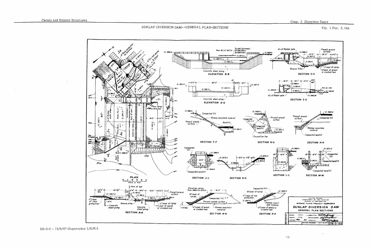
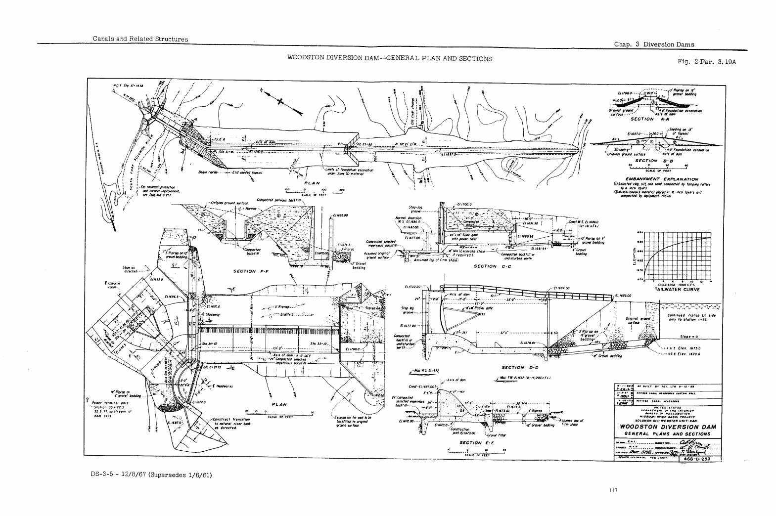
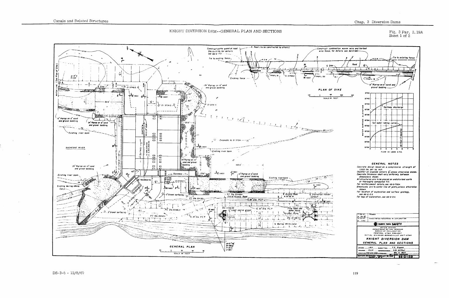
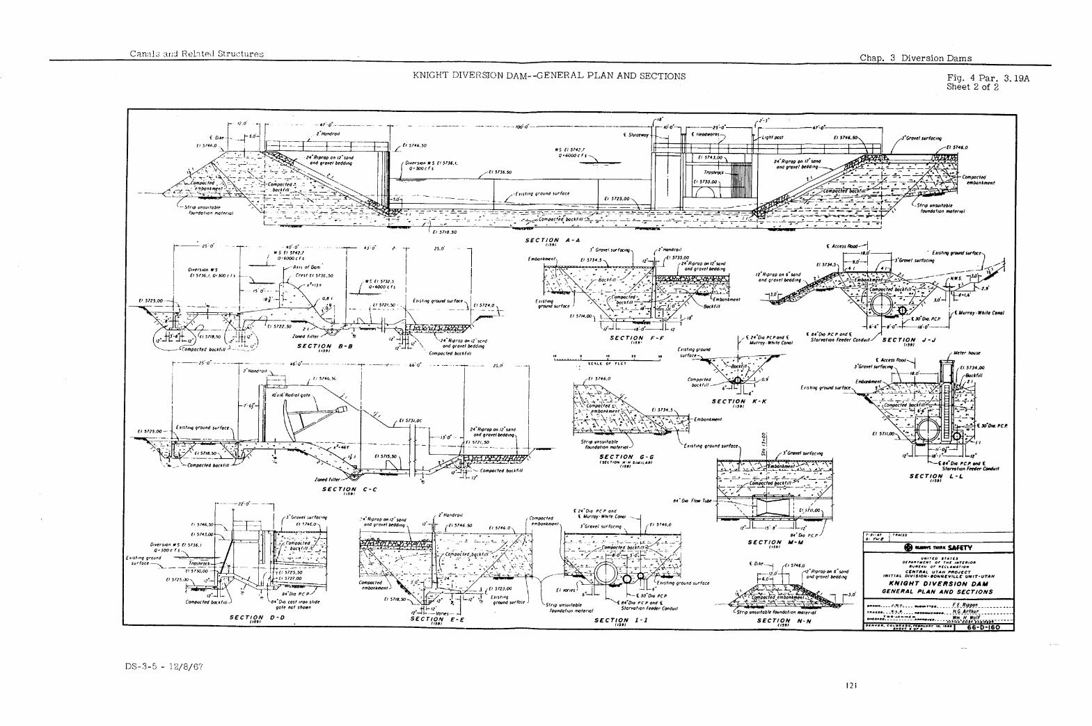
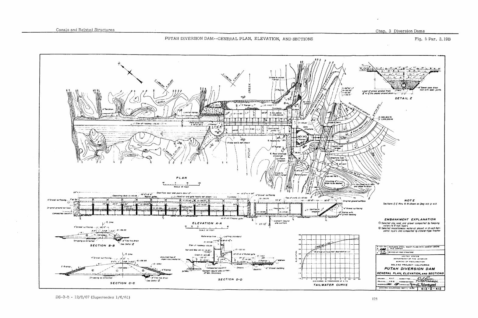
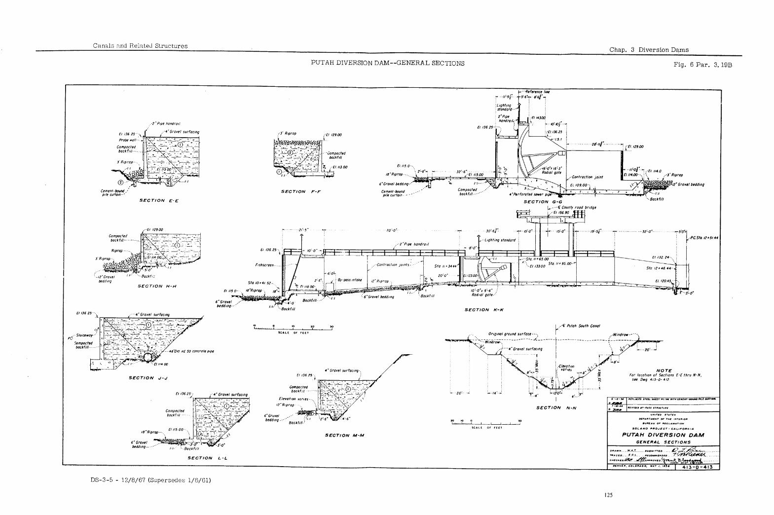
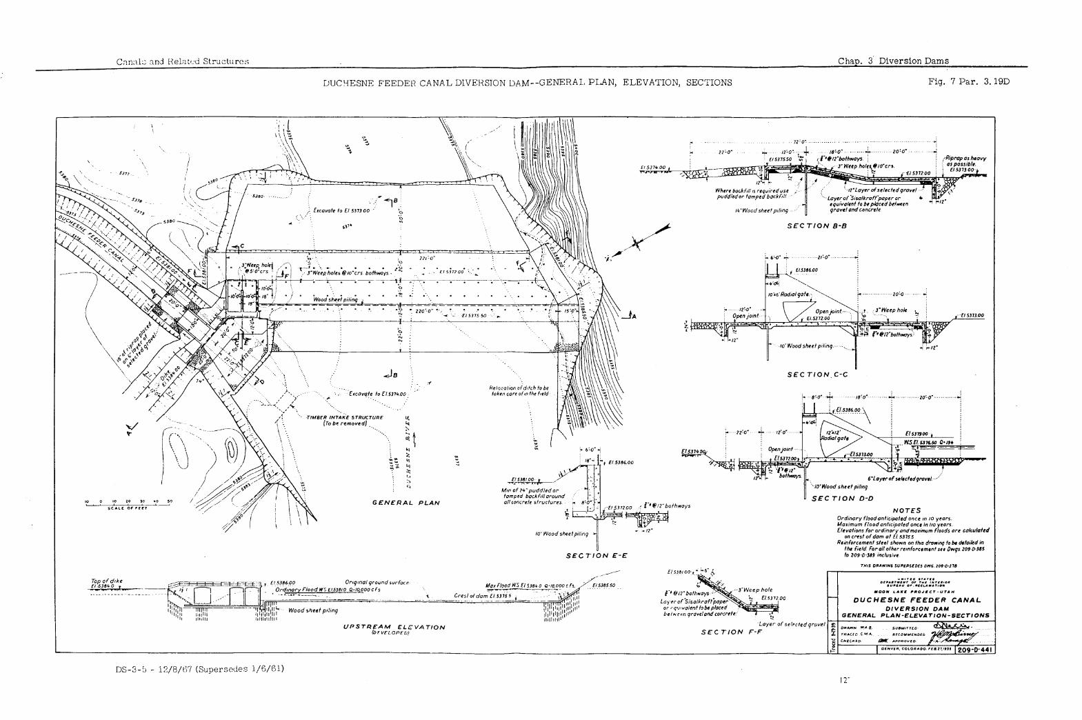
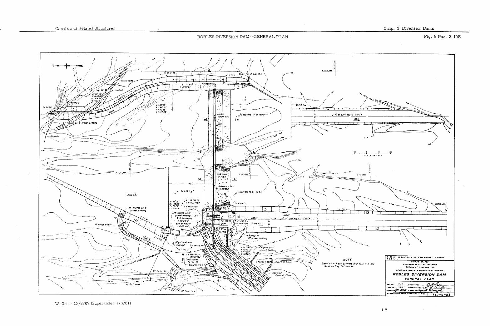
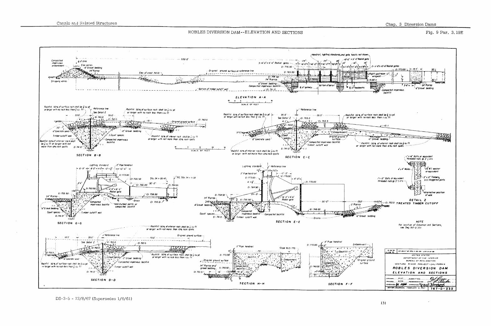
Canals and Related Structures Chap. 4 Diversion Headworks
TABLE OF CONTENTS
.- SPECIFIC DESIGN CONSIDERATIONS
GENERAL DESIGN CONSIDERATIONS
Paraqranh’
2:: 4:3
i-45 4:6
4.7
E 4: 10 4.11
4.12 Structural Relations 4.13 Special Sluicing Facilities--Guide Walls 4.13A Undersluice Type 4.14 Gate Selection 4.15 Stoplog Provision
4.16 Percolation 4.17 Energy Dissipation 4.18 Trashracks 4.19 Trashrack Bar Spacing 4.20 Trashrack Cleaning
4.21 4.22 4.23 4.23A 4.23B 4.24 4.25 4.26 4.27 4.28
Definition Function Location Relation to Other Structures Effect of Stream Curvature Foundation Conditions
CONTROL STRUCTURE TYPES
Form of S’cructure Radial-gate Open Type Radial-gate Submerged Type Closed Type Catch Basin Type
SLUICE AND GATE REQUIREMENTS
PROVISION FOR FISH PROTECTION
Need for Protection Classes of Fish Self-cleaning Mechanical Screens
Rotary Type Traveling Type
Stationary Bar Screens Louver Diverter Electric Screens Velocity of Approach to Screens Fish Bypass Channel
DS-3-5 - 12/8/6’7 133
Chap. 4 Diversion Headworks Canals and Related Structures
TABLE OF CONTENTS--Continued
LIST OF FIGURES
Figure Number
1
2
3
4
5
6
Title
Roza Diversion Dam--General Plan and Sections
Gila Valley Canal Headworks, Imperial Dam--General Plan and Sections
Milburn Diversion Dam--General Plan, Elevation, and Sections
Trashrack Rake Gantry, General Assembly--All-American Canal Headworks
Trashrack Rake Assemblies, List of Parts--All-American Canal Headworks
Trashrack Metalwork, Rack Unit, List of Parts--Gila Valley Canal Headworks
Florida Farmers Ditch Diversion Dam--Plan and Sections
Headworks Structure, Plan, and Sections--Contra Costa Canal
Tehama-Colusa Canal Louver Fish Diverter and Appurtenant Sructures-- Plan and Sections
Paragraph Drawing Reference Number
4. a
4.9
4.13A
4.20
4.20 212-D-3756
4.20 212-D-1597
4.23A 519-D-85
4.24 214-D-2732
4.25 602-D-996
33-D-1161 L
. 212-D-2422
499-D-55 *
212-D-3740
DS-3-5 - 12/S/67 134
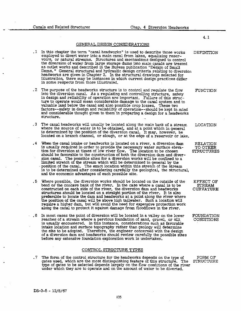
Canals and Related Structures Chap. 4 Diversion Headworks
.1
.2
.3
.4
.5
.6
.7
In this chapter the term “canal headworks” is used to describe those works employed to divert water into a main canal from lakes, equalizing reser- voirs, or natural streams. Structures and mechanisms designed to control the diversion of water from large storage dams into main canals are treated as outlet works and described in the Bureau publication “Design of Small Dams. ” General structural and hydraulic design criteria relating to diversion headworks are given in Chapter 2. In the structural drawings selected for illustration, there may be instances in which current design practices differ in some respects from those illustrated.
The purpose of the headworks structure is to control and regulate the flow into the diversion canal. As a regulating and controlling structure, safety in design and reliability of operation are important. Failure of this struc- ture to operate would mean considerable damage to the canal system and to valuable land below the canal and also possible crop losses. These two factors--safety in design and reliability of operation--should be kept in mind and considerable thought given to them in preparing a design for a headworks structure.
The canal headworks will usually be located along the main bank of a stream where the source of water is to be obtained, and at a point which in general is determined by the position of the diversion canal. It may, however, be located on a branch channel, or slough, or at the edge of a reservoir or lake.
When the canal intake or headworks is located on a river, a diversion dam is usually required in order to provide the necessary water surface eleva- tion for diversion at times of low river flow. The location to be chosen should be favorable to the construction of both the diversion dam and diver- sion canal. The possible sites for a diversion works will be confined to a limited stretch of the stream which will be determined in general by the position of the canal. The exact location within this stretch of the stream is to be determined after considering carefully the geological, the structural, and the economic advantages of each possible site.
Where possible, the diversion works should be located on the outside of the bend or the concave bank of the river. In the case where a canal is to be constructed on each side of the river, the diversion dam and headworks structures should be located on a straight portion of the river. It is also preferable to locate the dam and headworks at a point along the river where the position of the canal will be above high tailwater. Such a location will require a higher dam, but will avoid the need for expensive protection work along the canal to protect it against damage from floodflows in the river.
DS-3-5 - 12/8/67
In most cases the point of diversion will be located in a valley on the lower reaches of a stream where a pervious foundation of sand, gravel, or silt is usually encountered. In this instance, considerations such as favorable intake location and surface topography rather than geology will determine the site to be adopted. Therefore, the engineer concerned with the design of a diversion dam and headworks should review carefully the possible sites before any extensive foundation exploration work is undertaken.
The form of the control structure for the headworks depends on the type of gates used, which are the most distinguishing feature of this structure. The type of gates to be selected depends largely on the flow conditions of the river under which they are to operate and on the amount of water to be diverted.
GENERAL DESIGN CONSIDERATIONS
CONTROL STRUCTURE TYPES
4.1
DEFINITION
FUNCTION
LOCATION
RELATION TO OTHER
STRUCTURES
EFFECT OF STREAM
CURVATURE
FOUNDATION CONDITIONS
FORM OF STRUCTURE
13s
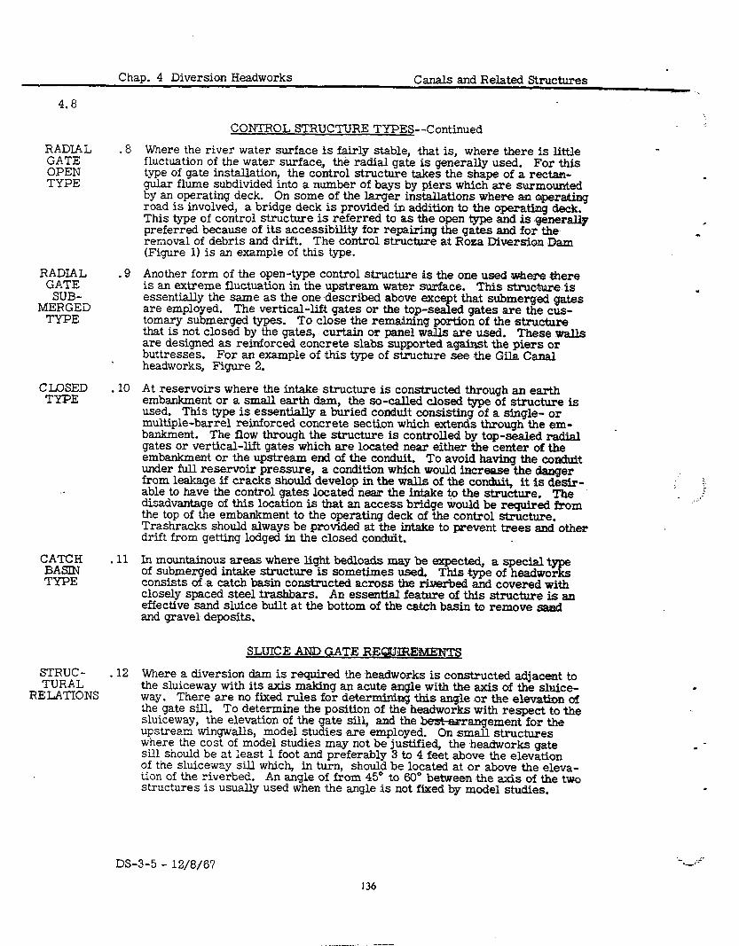
4.8
Chap. 4 Diversion Headworks Canals and Related Structures
CONTROL STRUCTURE TYPES--Continued
RADIAL .8 GATE
Where the river water surface is fairly stable, .that is, where there is little
OPEN fluctuation of the water surface, the radial gate is generally used. For this
TYPE type of gate installation, the control structure takes the shape of a rectan- gular flume subdivided into a number of bays by piers which are surmounted by an operating deck. On some of the larger installations where an opera&,ing road is involved, a bridge deck is provided in addition to the operating deck. This type of control structure is referred to as the open type ,and is general@ preferred because of its accessibility for repairing the gates and for the removal of debris and drift. The control structure at Roea Diversion Dam (Figure 1) is an example of this type.
RADIAL GATE
SUB- MERGED
TYPE
-9 Another form of the open-type control structure is tie one used ,where .there is an extreme fluctuation in the upstream water surface. This structure is essentially the same as the one described above except that submerged gates are employed. The vertical-lift gates or the top-sealed gates are the cus- tomary submerged types. To close the remaining portion of the structure that is not closed by the gates, curtain or panel wails are used. These walls are designed as reinforced eoncrete slabs supported against the piers or buttresses. For an example of this type of structure see .the Gila Canal headworks, Figure 2.
.
CLOSED I 10 TYPE
At reservoirs where the intake. structure is constructed through an earth embankment or a small earth dam, the so-&.Ued closed type of structure is used. This type is essentially a buried conduit consisting of a single- or multiple-barrel reinforced concrete section which extends through the em- bankment. The flow through the structure is controlled by top-sealed radial gates or vertical-lift gates which are located near either the center of the embankment or the upstream end of the conduit. To avoid having the conduit under full reservoir pressure, a condition which would increase the danger from leakage if cracks should develop in the walls of the conduit, it is desir- able to have the control gates located near the intake to the structure. The disadvantage of this location is that an access bridge would be required from the top of the embankment to the operating deck of the control structure. Trashracks should always be provided at the intake to preve.nt trees and other drift from getting lodged in the closed condtit.
i . ; i*
CATCH BASIN TYPE
STRUC - TURAL
RELATIONS
. 11 In mountainous areas where light bedloads may be expected, a special type of submerged intake structure is sometimes used. This type of headworks consists of .a catch basin constructed across the riverbed and covered with closely spaced steel trashbars. An essentia.I feature of this structure is an effective sand siuice built at the bottom of tht? catch basin to remove ,saa~I and gravel deposits.
-12
SLUICE AND GATE REQUIREWENTS
Where a diversion dam is required the .headworks is constructed adjacent to the sluiceway with its axis making an acute angle with the axis of the sluice- way. There are no fixed rules for determining this angle .or the elevation of the gate sill. To determine the position of the ,headworks with respect to the sluiceway, the elevation of the gate sill, and the &s&arrangement for the upstream wingwalls, model studies are employed. On small structures where the cost of model studies may not be justified, the .headworks gate sill should be at ieast 1 foot and preferably 3 to 4 feet above the elevation of the sluice-way sill which, in turn, should be located at or above the eleva- tion of the riverbed. An angle of from 45” to 60” between the axis of the two structures is usually used when the angle is not fixed by model studies.
.
.
DS-3-5 - 12/8/67
136
Canals and Related Structures Chap. 4 Diversion Headworks
4.13
SLUICE AND GATE REQUIREMENTS--Continued
. 13 Figure 2 in Chapter 3 shows curved guide walls approaching the canal head- SPECIAL works and the sluiceway. This facility creates curvature in normal flows SLUICING approaching the headworks, so, in effect, diverted water is taken from the FACILITIES outside of the curve where the sediment bedload is least and the heavier GUIDE silt-laden water is taken through the sluiceway.. Model studies must be WALLS employed to set the most efficient proportions and curvature of the walls. The top of the inner guide wall is usually set at the overflow weir elevation.
A. Figure 3 shows an undersluice arrangement as a special sluicing facility. Undersluice The top of the undersluice is placed at the same elevation as the head- works gate sill, and the elevation of the sluiceway gate sill is made the
Tn=
same as that of the upstream apron. This arrangement guides the heavier sediment into the sluiceway and prevents it from entering the headworks. A disadvantage of this type is that the undersluice is sub- ject to plugging with waterlogged debris. facilities depends on continuous sluicing.
Success of both of the above
. .
. 14 The number and size of gates to be selected depends to a large extert on the GATE judgment of the designer. The total gate opening required for a given dis- SELECTION charge is generally based on an allowable velocity of 4 to 6 feet per second. From an operating point of view, a single gate is desirable; but when more than one gate is installed they should be operated in parallel to avoid un- symmetrical flow. On rivers where considerable fluctuation in water sur- face can be expected during the irrigation season when the gates are in operation, they should be controlled automatically. The controls are operated by means of a floatwell or probewell to control the water surface in the canal downstream from the gate. Requirements for heating of the gates should be considered and the design of operating features should be compatible with remote control requirements.
. 15 To permit closure of the structure during an emergency and to permit main- STOPLOG tenance work on the gates, it is customary to make provision for stoplogs PROVISION by providing grooves in the piers. The grooves are usually made by form- ing recesses in the piers, the depth being determined by the allowable bear- ing stress of the timber. The grooves should not be made too wide because this would permit the stoplogs to turn and bind. Continuous steel angles should be provided at the outer downstream edge of the grooves for protection and to reduce the frictional res%ance when removing the stoplogs.
SPECIFIC DESIGN CONSIDERATIONS
.16 In the majority of cases the headworks will be constructed on permeable PERCOLATION material, and it will be necessary to consider the effect of underflow and the hydrostatic uplift pressure when making stability and design studies. The head causing percolation is to be taken as the difference between the maximum elevation of the water surface in the river and the elevation of the bottom of the canal. Lane’s weighted creep theory or electric analogy is used in determining the percolation path required. For the ordinary, open-type structure the required path is furnished by extending the upstream apron and cutoff wall of the dam across and in front of the headworks and providing an additional cutoff wall if necessary. For the closed type of structure, the path is furnished by constructing continuous concrete collars or cutoff walls at intervals along the conduit. Hydrostatic pressure produced by water percolating along the outside of the structure should be considered in designing the walls. To prevent the foundation material from being re- moved by the percolating water, a filter should be constructed under the structure at its downstream edge.
DS-3-5 - 12/8/67
137
-0.. Chap. 4 Diversion Iiea;iwork:, C:.:nals and Rshted Structures
4.17
SPECIFl!~ DESIGl< CONSLDEii,4’1’IC;NS--Cvntinai,ti
ENERGY . 17 DISSII’A -
TION
Some means of CliSSipX:ili:j iiiU CiCCL5 ener:.v a in the river should be’ p:-;Jvidd
? times A tli(Jti w:l ter surface
dissipating this excess energy. The Ilydraulifc jump is favored :IS means of
In order to confine the jump, n stilling pool downstream from the gates is required. In the case of the closed type of headworks, the hydraulic jump may trike place in the stilling pool provided in the closed conduit. ‘I’d avoid undesirable disturbance from the jump and to maintain free-flow conditions, ample freeboard should be provided in the closed ccnduit from the control gntcs to the outlet. Were sufficient head is available it would be desirable to have the water fiow nt supercritical velocity through the conduit and to have the stilling pool located beyond the outlet to avoid objectionable vibration of the structure under the embankment. It is important that consideration be given not only to flow condition at maximum discharge but also a? partial discharges. The structure must operate satis- factorily under all possible conditions of flow.
TRASH- .18 RACKS
Trashracks are desirable at the entrance to some headworks structures and are essential where fish screens and desilting works are involved. Racks usually are constructed of flat steel bars which are pet on edge and either joined by through bolts with pipe nipples for spacers or welded to the edges of the crossbars. The welded type is preferred as it provides more space for the rake teeth to pass between the bars. in panels for ease in handling.
The racks are generally made ‘1’0 facilitate cleaning, they are usually
inclined on a slope of 1 horizontal to 4 vertical a.nd the velocity of flow through the gross area should not exceed 3 feet per second.
TRASH- .19 RACK BAR
SPACING . .
TRASH- ,2d RACK
CLEANING
Rack bars are spaced 1 to 4 inches for fine trashracks and 4 to 12 inches for coarse racks. For headworks where the rotary type of fish screens are in- stalled and heavy oedloads are expected, closely spaced bars should be used at the lower units to prevent the larger sized gravel from becoming lodged against the screens.
On small headworks the racks are usually rr&ed by hand, but on larger in- stallations mechanical rakes are nearly always provided. Some means of disposing of the rakings should be given adequate consideration. A typical mechanical rake, rake gantry, and disposal car that are used at the All- American Canal headworks for cleaning the trashrack are shown in Figures 4 and 5. An exampie of a bar-type trashrack is illustrated in Figure 6.
PROVISION FOR FISH PROTECTION
NEED FOR .21 PROTEC-
TION
The growing importance of sport fishing and the need for protecting the com- mercial fish industry makes necessary the screening of many irrigation and power canal intakes. To protect these interests, many States have enacted laws requiring the screening of diversions. Since the design requirements for fish screens may vary in the different States, Federal, State, and local agencies concerned with the preservation of fish life must be consulted before any designs of fish screens are made.
CLASSES .22
l%H
-The problem of fish protection involves two classes of fish with quite different habits--the mi.gratory fish, such as the salmon and the steelhead trout, and the sedentary species which confine their movements to limited areas only in search for food. From a commercial point of view, the salmon is the most important. The sportsman is interested in both classes.
SELF- .23 CLEANING
To protect the fingerlings from being lost in the canals on their journey en-
MECHANICAL route from their spawning grounds to the ocean, fine-mesh screens at canal intake are necessary.
SCREENS These screens may have openings as small as four to
six meshes per inch which makes them very difficult to keep clean. Keeping
DS-3-5 - 12/8/67
? a-
. . a’
L
I -
,-.:-
138
.24
.25
Canals and Related Structures Chap. 4 Diversion Headworks
PROVISION FOR FISH PROTECTION--Continued
these fine-mesh screens from being clogged with floating debris and leaves SELF- is one of the major problems in designing a fish screen. To overcome this CLEANING difficulty several types of self-cleaning mechanical screens have been devel- MECHANICAL oped, namely the rotary-drum type and the traveling screens which are simi- SCREENS lar to the industrial water screens. (Cont’d. 1
A. The rotary-drum screens are very sensitive to changes in water level and are adaptable only where there will be little fluctuation in water sur- face. The water depth is limited by the size of the drums. To effec- tively remove the floating debris without loss of fish over the screens, from 0.1 to 0.3 of the diameter of the drum should extend above the water surface. The required circumferential speed of the drum will depend on the amount of debris being carried by the streams, the maxi- mum speed is about 5 feet per minute. This type of screen consists of structural steel cylinders covered with a fine-mesh screen and supported by a horizontal steel shaft. The drums can either be propelled by means of a waterwheel located downstream or be motor-driven. The fish screens installed at the Florida Farmers Ditch Diversion Dam are of the rotary-drum type. (See Figure 7. ) Instead of installing drum screens normal to the flow, recently some fishery authorities prefer placing the screens at an angle of 20” to 30” with the flow. This is to facilitate diverting fish into bypasses.
B. Where there is a wide operating range in the water surface, the travel- ing or industrial water screens are more adaptable as they can be con- structed for almost any depth of water. This type of screen is made up in units. Each unit consists of a continuous belt of overlapping screen trays which are fastened between two parallel link belts operated from two sets of sprockets. The sprockets are mounted on a structural steel frame with the head or driven sprocket located at the top of the frame and the foot or nondriven sprocket located at the bottom. The head sprocket is driven by a gear speed-reducer, roller-chain drive, and motor. To dislodge debris that becomes lodged against the screen trays, a series of water jets are provided on the downstream underside of the trays at a point above the high water level.
At locations where the size of the fish are such that an extremely fine screen is not required, the stationary-bar type of screen is sometimes used. The bar screen can be constructed for almost any fluctuation in water surface but is somewhat difficult to keep clean. An example of this type of screen which is kept clean by means of a motor-driven sweep is the Contra Costa fish screens, Figure 8.
The louver system of guiding migratory fish into bypasses is a recent devel- opment in fish screens for canal headworks at river diversions. The system consists of a series of vertical bars with l-inch clear spacings and flow- straightening vanes Set in a single row or multiple rows across a channel, each row at an angle of about 15” to the direction of flow. The fish are diverted away from the louvr line to a vertical bypass at the downstream end. The bypass covers the full depth of flow and the minimum width is 12 inches. The velocity of flow entering the bypass should be about 1.4 times the channel velocitqr. The success of this screening system depends on the fish sensing the turbulence around the louver bars. An example of this type screens is the Tehama-Colusa Canal louver fish diverter, Figure 9.
Another type of stationary fish screen that appears to have possibilities is the electric fish screen. The principal parts of this screen are the elec- tronic impulse generator which employs the industrial-type vacuum tube,
DS-3-5 - 12/8/67 139
4.23A
Rotary Type
Traveling Type
BAR SCREENS
LOUVER DIVERTER
ELECTRIC SCREENS
. Chap. 4 Diversion Headworks Canals and Related Structures
4.27
VELOCITY
APP!:ACH
SC&NS
FISH BYPASS
CHANNEL
.27
.28
PROVISION FOR FISH PROTECTION--Continued
the live electrode, and the ground conductor. The live galvanized pipe elec- trodes are suspended vertically to swing freely from an overhead beam or catenary cable supported by structural steel supports on each side of the canal. Random lengths of galvanized pipe strung on a cable and joined elec- trically by a copper wire are placed along the bottom of the channel to form the ground conductor. The electric screen has the advantage of low cost and it allows all types of stream-carried debris to pass through without obstruct- ing the flow of water. of power.
This screen is entirely dependent on a reliable supply The efficiency of the electric fish screen has been questioned by
Fish and Wildlife authorities and there are some conflicting opinions regard- ing its effectiveness in stopping the fish. Consequently, a thorough investi- gation of existing installations should be made when considering the use of this type of screen.
In the design of all types of fish screens, the velocity of approach is import- ant. In the case of mechanical screens, the approach velocity should not exceed 1.5 feet per second in order to keep the fish from being held against the screens by the force of the current. Low velocities are also necessary where electric screens are. used to avoid having the fish carried helplessly through the electrified zone. To maintain screening efficiency for louver diverters the velocity of approach should be from 2.5 to 4.0 feet per second to create optimum turbulence.
Another important feature in connection with the design of fish screens is the fish bypass channel. When the small fish are traveling downstream and are stopped by the screens, it is believed that they will not turn back but will find a way through or past the screens, or destroy themselves trying. There- fore, a suitable downstream bypass should be provided to allow an alternative route for the fish when stopped by the screens to return to the main stream.
DS-3-5 - 12/8/67 140
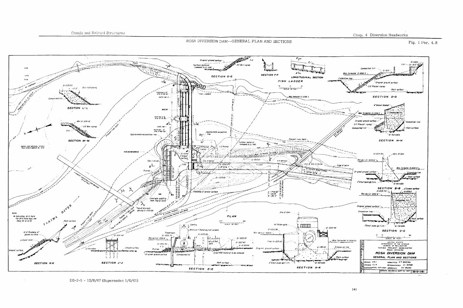
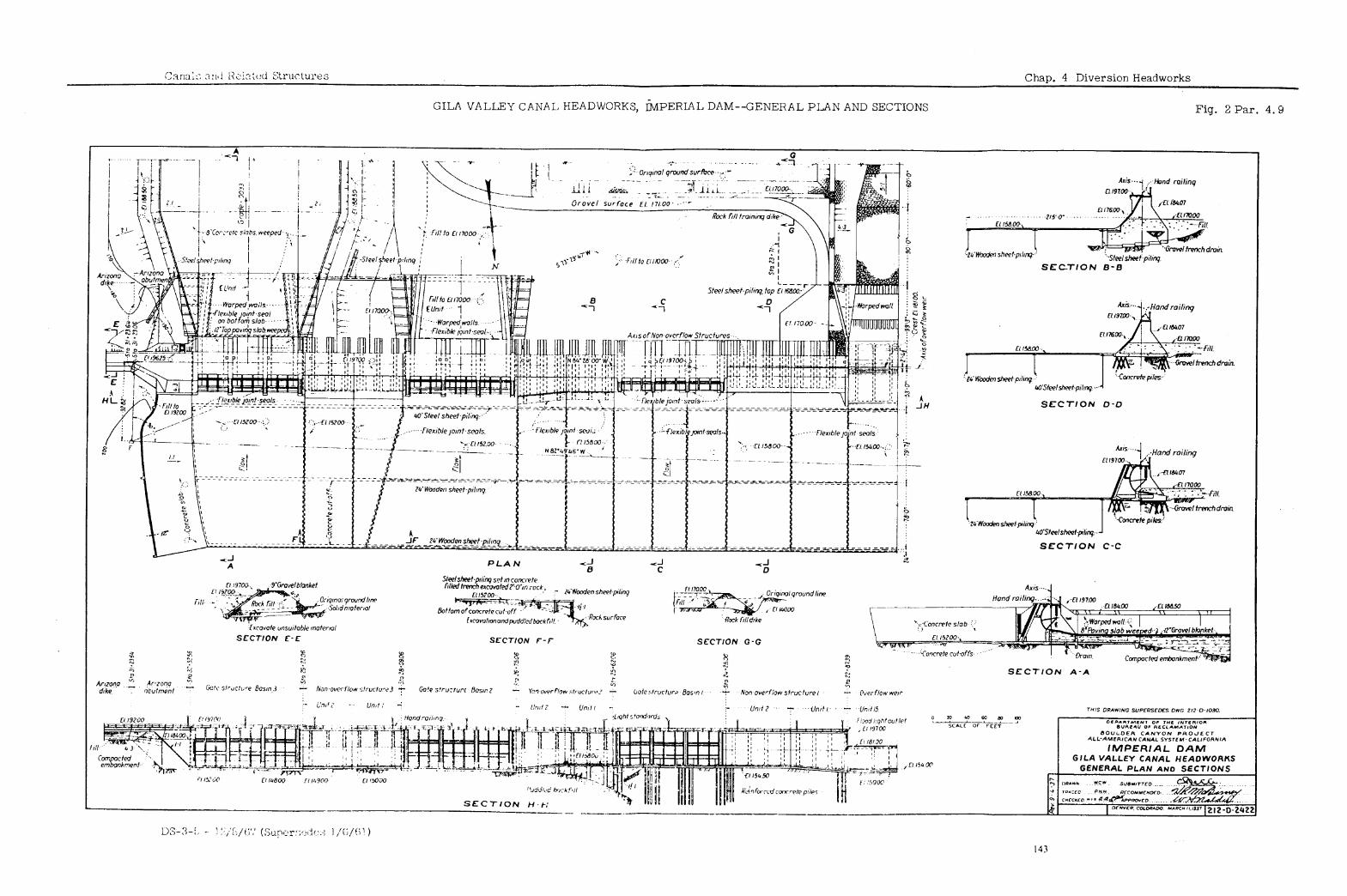
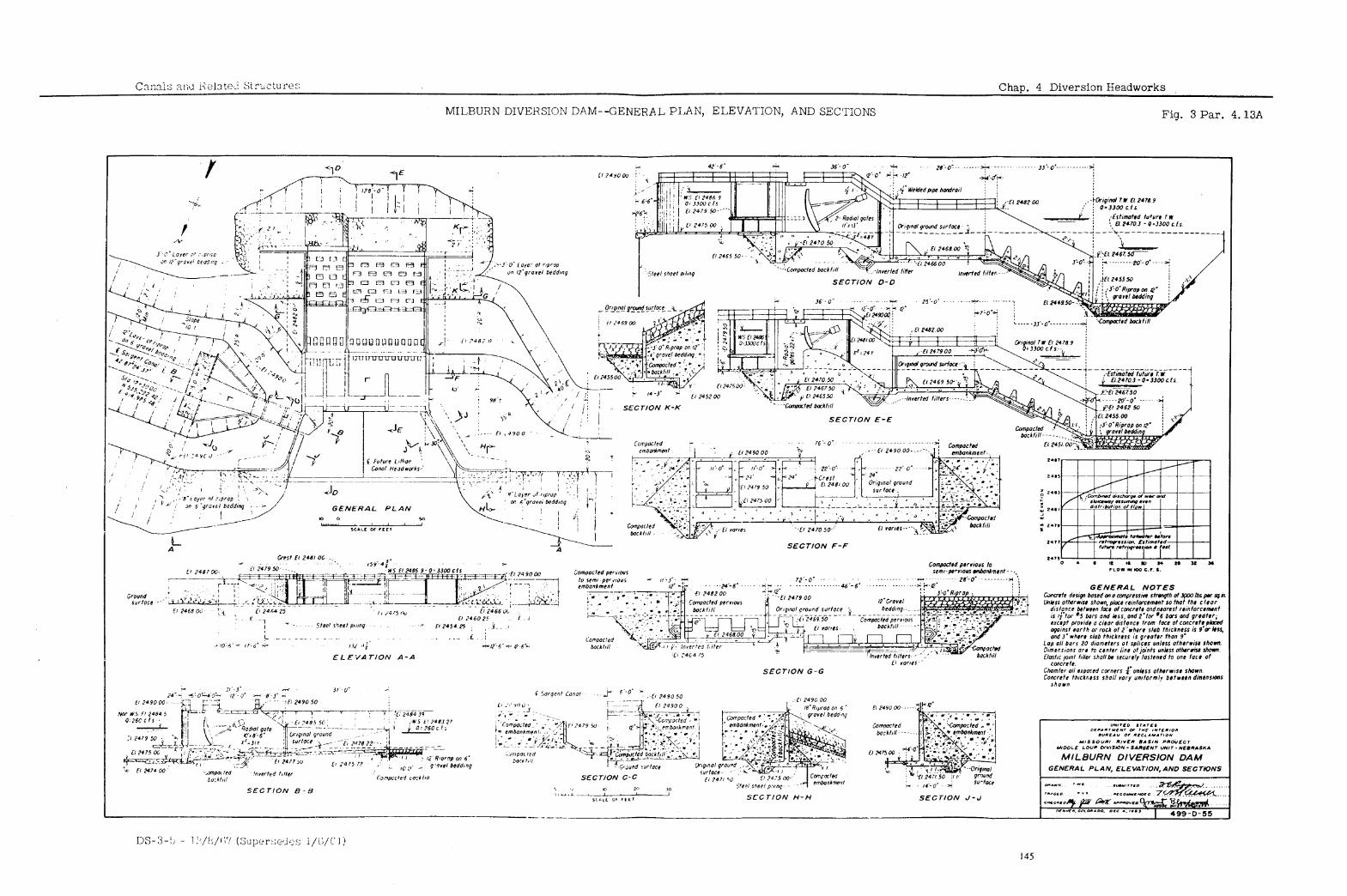
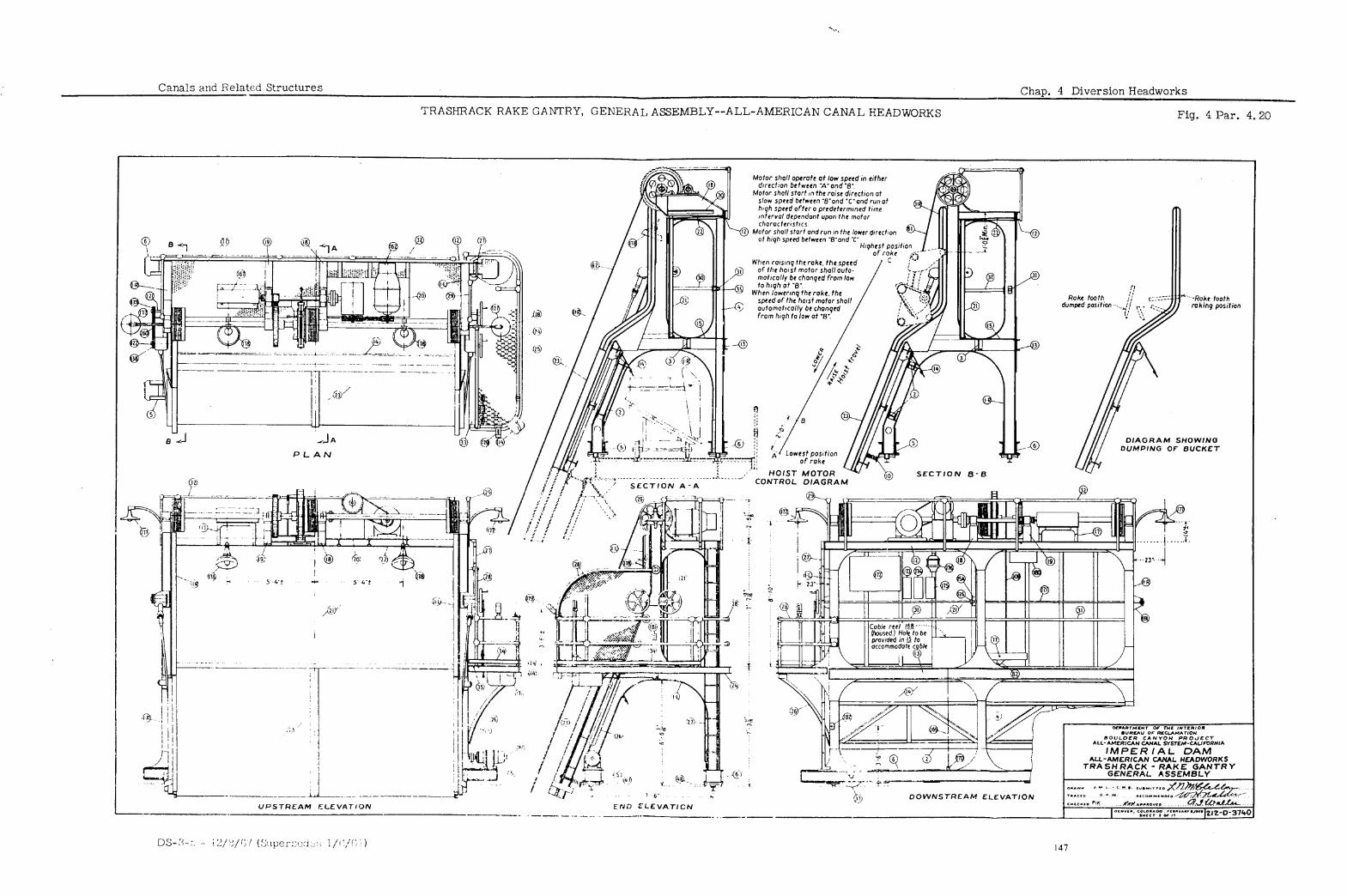
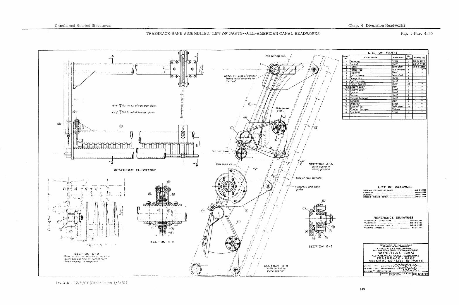
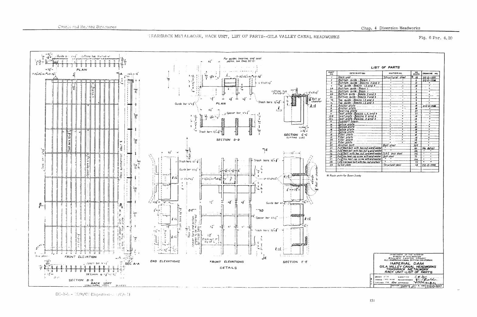
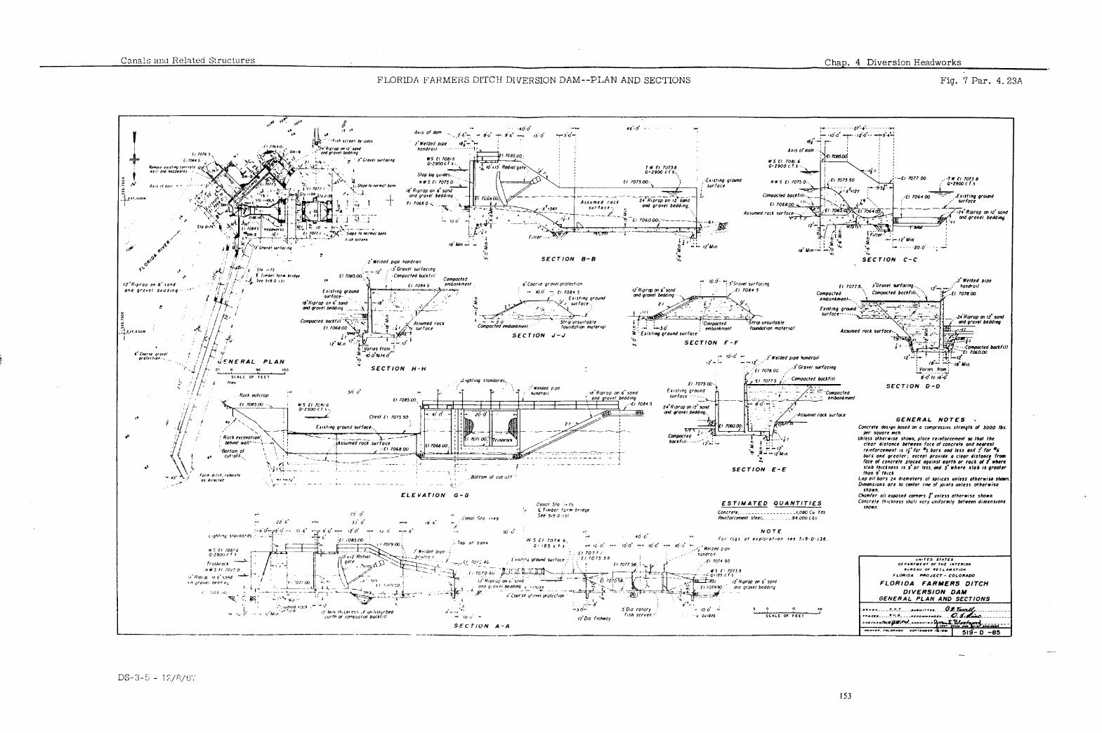
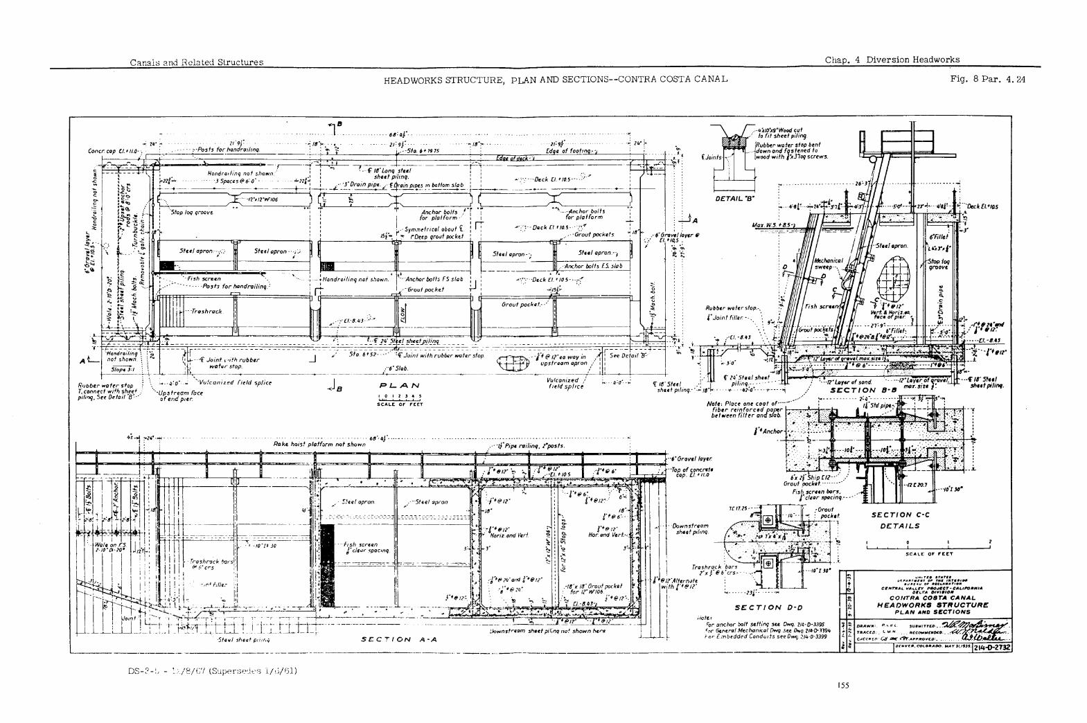
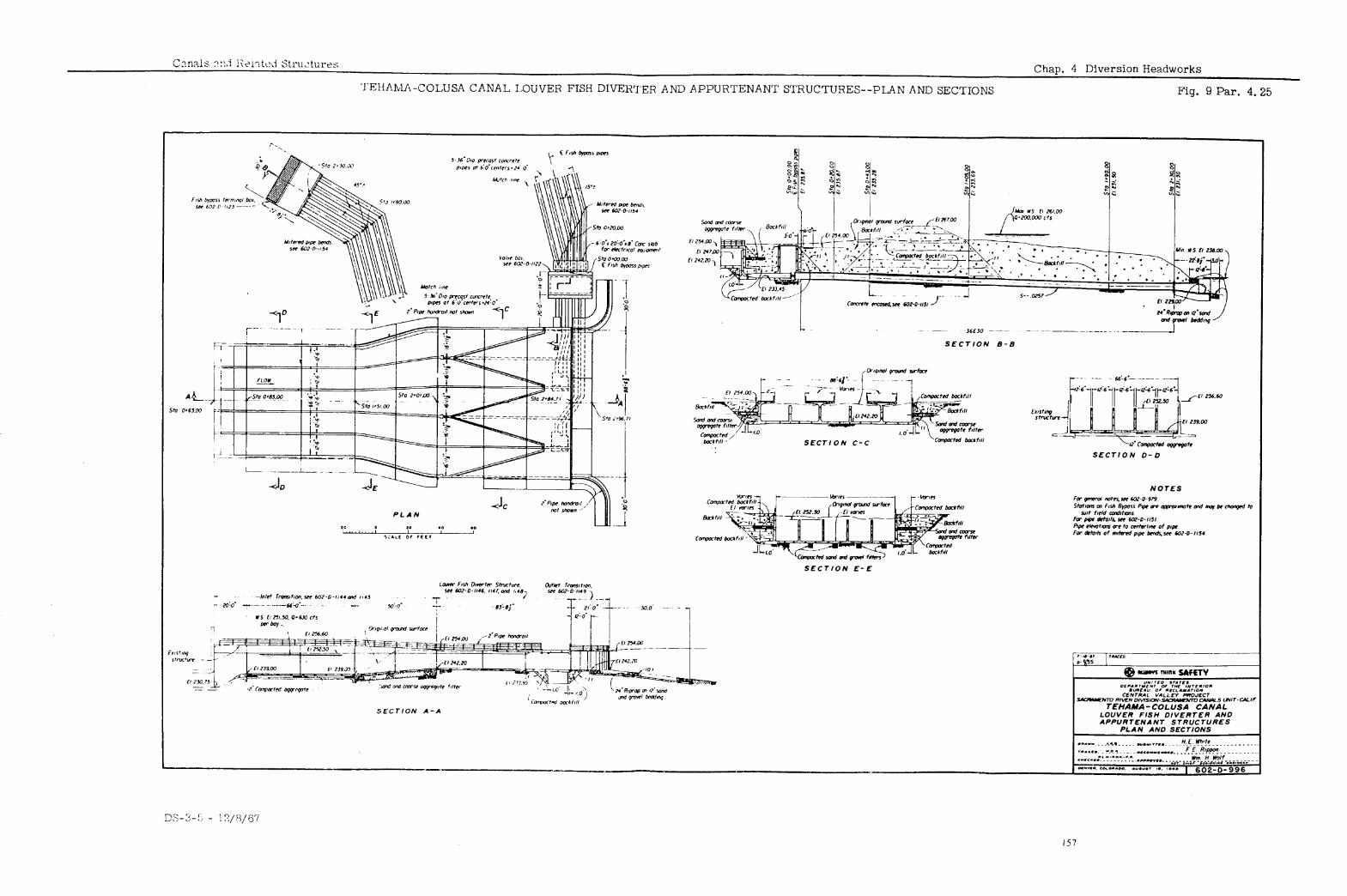
Canals and Related Structures Chap. 5 Canal StZWttEeS
TABLE OF CONTENTS
Paraaranh
5.1
E 5: 3A 5.3B
E 5: 5A 5.5B
i:i . Eo 5:11 5.12 5.13
._ 5.14 5. 14A 5.14B 5.14c 5.14D 5.15
5.16 5.16A 5.16B. 5.17 5.17A 5.17B 5.17c 5.17D 5.17E 5.18 5.18A 5.19
5.20 General 5.21 Length and Freeboard 5.22 Chute and Pool Blocks 5.23 Outlet
Introduction
INVERTED SIPHONS
Definition Barrel Types
Circular Sections Box Sections
Head Loss Appurtenances
Blowoff Protective Features
TUNNELS
General Portals Dimensions Head Loss Supports “A” and “B1’ Lines Grouting and Draining Protective Features
CHECKS
Function, Arrangement, and Types of Control Radial Gates Slide Gates stop Planks Protective Features
Head Loss
FLUXES, CHUTES AND DROPS
Flumes Flume Section Hydraulics
Chu;:~ and Inclined Drops
Chute Channel and Tapered Transitions Trajectory Chute Wall Height and Freeboard Stilling Pool
Vertical Drops Dimensions
Closed Conduit Drops
STILLING POOLS
-
DS-3-5 - 12/8/67 159
Chap. 5 Canal Structures Canals and Related Structures
TABLE OF CONTENTS--Continued
.: BAFFLED APRONS
Paraaraph
5.24 General 5.25 Dimensions
.
TURNOUTS
DS-3-5 - 12/8/67
L
c
.
,’
Canals and Related Structures Chap. 5 Canal Structures
TABLE OF CONTENTS--Continued
Figure Number
1
4
5
6
7
8
9
10
11
12
13
14
28
LIST OF FIGURES
Paragraph Reference
Two Medicine Siphon--Precast Concrete Pipe Barrel
Two Medicine Siphon--Transitions Typical Inlet Transition with Check--
66-, 72-, and 78-inch Pipe Diameters 8.9 Siphon, Main Canal, Navajo Indian
Irrigation Project--Monolithic Barrel Profile
Typical Monolithic Siphon Barrels-- Heads 0 to 100 feet
Stoney Creek Siphon with Check-- Plan and Sections
Head Loss Determination for Monolithic Concrete Siphons
Typical Blowoff for Monolithic Concrete Pipe
Water Hollow Tunnel--Alinement, Profile and Sections
Water Hollow Tunnel--Typical Supports for Horseshoe Tunnel
Water Hollow Tunnel--Typical Supports for Machine-bored Tunnel
River Mountains Tunnel--Alinement, Profile and Sections
River Mountains Tunnel--Sections and Details for Circular Tunnels
Tunnel No. 3-A Portal Areas, Main Canal, Navajo Indian Irrigation Project--General Plan and Profile
Tunnel Portal Transition-- Dimension Formulae
Horseshoe Gravity Tunnels (Concrete Lined)--Capacity Curves
Check No. 5, San Luis Canal-- Plan and Sections
Wahluke Branch Canal Station 1356t25-- Check
Checks--Type 10 A G Checks--Type 13 A G Stop Plank Grooves--Standard Designs Structural Steel Liners--Standard
Designs Stop Planks (Wood)--Design Charts Typical Rectangular Chutes and
Rectangular Inclined Drops Parshall Flume and Chute--
Eltopia Branch Canal Stilling Pool--Eltopia Branch Canal Radial Gate Check Drop--
Mohawk Canal Stilling Pool Dimensions for
Vertical Drops Pipe Drops Types 1 and 2 Baffled Apron Drops--Saddle
Mountain ‘Wasteway
DS-3-5 - 12/8/67
5.3A 2-D-85 5.3A 2-D-84
5.3A 304-D-126
5.3A 809-D-159
5.3A 809-D-175
5.3B 602-D-1184
5.4 103-D-633
5.5A 465-D-301
5.6 66-D-120
5.6 66-D-224
5.6. 66-D-258
5.6 952-D-16
5.6 952-D-19
5.7
5.8
5.9
809-D-203
40-D-2011
103-D-637
5.14A
!i.l4A
E%i 5: 14C
805-D-2151
222-D-21839 222-D-22195 222-D-22196 40-O-5326
5.14c 5.14C
5.17
40-D-5907 X-D-1305
5r 17 5.17
5.18
5.18A 5. 19
5.24
103-D-642
222-D-20934 222-D-20935
50-D-2817
103-D-641 103-D-635
222-D-21878
161
Canals and Related Structures Chap. 5 Canal Structures
5. 1
.1
.2
.3
The following paragraphs deal with commonly used canal and lateral strut- INTRODUCTION tures except water measurement structures, cross-drainage structures, protective structures, and bridges, which are described in following chap- ters. General structural and hydraulic design criteria relating to canal and lateral structures are given .h Chapter 2. In the structural drawings selected for illustration, there may be instances in which current design practices differ in some respects from those illustrated.
SIPHONS
A siphon (sometimes called an inverted siphon, sag pipe, or sag line) is a closed conduit designed to run full, and usually under pressure, that trans- ports canal and lateral water by gravity under railroads, roads, various types of drainage channels, and depressions.
DEFINITION
The shape and number of barrels will be governed by the local conditions and BARREL economy. The shape of the skctions most commonly used are circular and TYPES rectangular, although trapezoidal and other shapes have been used for specific requirements.
A. Precast concrete pressure pipe and monolithic concrete pipes are the circular most common types of circular siphon barrels used for heads up to about 125 feet.
Sections Plate steel, monolithic concrete with steel liner, precast con-
crete with steel cylinder, pretensioned concrete, prestressed concrete, asbestos cement., and cast iron pipe are usually used for higher heads. Precast concrete pressure pipe is normally used for diameters up to about 96 inches; however, larger sizes have been used in some areas. Monolithic concrete pipe is generally used for diameters larger than 96 inches and in some areas for smaller sizes. Chapter 2 gives allow- able stresses for monolithic circular barrels under bursting heads. Figures 1 and 2 of this chapter show the layout and details for a siphon comprised of 96-inch-diameter precast concrete pressure pipe. ure 3 shows an inlet transition with cheek.
Fig- Figure 4 shows a 210-inch-
diameter siphon, and Figure 5 shows the reinforcement details for the siphon barrel. Ultimate load analysis is generally used for the design of precast and monolithic concrete pipe.
B. Rectangular single- or multiple-barrel box sections are often used for BOX short siphons when the head is 30 feet or less on the inside top of the Sections box. Figure 6 shows a box siphon with concrete-lined canal. A trape- zoidal box siphon is used occasionally for short siphons with little or no sump when it is important to keep the head loss to a minimum.
.4 Normally, the head loss through a siphon should include friction losses in HEAD transitions and barrel, inlet convergence and outlet divergence losses, bend Loss losses, and check loss when a check is installed in the transition. A lo- percent safety factor is usually added to all losses. Figure 7 shows a pro- cedure for determining head losses for concrete siphons: (For design details, . see Chapter 2. ) For long siphons where conditions may result in operation when the inlet is not sealed, the design should be checked with Figure 12 in Chapter 2 to insure satisfactory operation. Although available head and econ- omy usually determine the barrel’ size, where sand or other abrasive material is carried by the water it is desirable to limit the velocity to about 10 feet per second. 1. 5Ahv
For minimum hydraulic loss, it is desirable to provide a seal of (3 inches minimum) at the inlet headwall measured from the upstream ----*. c 3 . . . . . . . - -- water surface ana no suomergence at tne outlet neadwall.
DS-3-5 - 12/8/67 163
5.5
APPURTE- NANCES
Blowoff
Protective Features
GENERAL
PORTALS
Chap. 5 Canal Structures Canals and Related Structures
SIPHONS--Continued
.5 The following appurtenances are required at siphons as indicated:
A. A blowoff should be installed at or near the low point of a siphon if it is impracticable to empty the siphon by pumping from the lower end. In some instances it has been considered economical to break into 24-inch- diameter and smaller siphons instead of providing blowoffs for draining.
emergency Figure 8 shows details of a simple blowoff structure.
B. Protecti features shall be provided for all siphons (Class A, B, and C exposur r ) over 30 inches in diameter. Refer to Chapter 3, Safety Design Standards, of Design Standards No. 1 for specific requirements.
TUNNELS
.6 Where a canal would be in deep cut or on unstable slopes, a tunnel can often be justified as an alternative to an open-canal location on the basis of econ- omy, low maintenance cost, and safety of operation. A tunnel may also be the most economical means for carrying water from one watershed to another. Such tunnels are usually free-flow conduits lined with concrete and designed for a maximum water depth equal to about 0.82 times the tunnel height, with a minimum freeboard of 18 inches. If tunnel excavation is by blasting methods, a horseshoe section is generally used for free-flow tunnels and a circular section is used for tunnels operating under hydrostatic head, such as pressure tunnels in power systems. If tunnel excavation is by boring machines, the tunnel section is circular and differs in detail from the cir- cular section constructed by blasting methods. tunnel section details.
Figures 9 through 13 show
The size of most tunnels is determined by an economic study based on capac- ity required, construction cost, and value of head loss. Accessibility of the ends of the tunnel, adits, and shafts as well as geol data are required to determine the design and feasib %
‘cal and ground-water ty of a umnel.
disposal areas should be provided for tunnel excavation. Ample
In long tunnels, the possibility of adits at saddles or canyons and shafts at low cover points should be considered for their construction advantages. Permanent access should be provided in all tunnels for inspection and maintenance, and station markers should be provided at about 1, OOO-foot intervals in long tunnels.
-7 Tunnel portals should usually be located where the depth of cover over the tunnel is twice the tunnel diameter or 20 feet minimum in rock, and three times the diameter or 30 feet minimum in common material.
The slopes of the portal cuts should be flat enough to avoid excessive raveling of unstable bank material. surface drainage channels.
Portals should not normally be located in natural Cut-and-cover sections may extend beyond the
portal where the stability of the material is doubtful. Transitioning of the flow from open canal or flume to a free-flow tunnel is normally made in two -I---. steps:
.
i-
DS-3-5 - 12/8/67 164
.8
.9
.10
.11
.12
Canals and Related Structures Chap. 5 Canal Structures
TUNNELS--Continued
(1) From open canal or flume to a rectangular section at the tunnel pertal; and
(2) From the portal to the tunnel section. (See Figure 14.)
Tunnels may very in shape and size, but usually a minimum finished height of 6 or 7 feet, depending on tunnel length, is used to allow for use of stand- ard equipment and working room during construction. Cross sections larger than the minimum should be determined by capacity requirements and eco- nomic studies. Where horizontal curves are necessary in a tunnel, the radius should be adequate to allow for unrestricted movement of construction’equip- ment. Figure 15 gives dimensional formulae for tunnel portal transitions.
Normally, the head loss through a tunnel should include friction losses in transitions and in the tunnel sections, inlet convergence and outlet divergence losses, and bend losses. For design details, see Chapter 2. Where sand or other abrasive material is carried by the water, it is desirable to limit the velocity to about 10 feet per second. For clear water transportation, the only limitation of velocity in a free-flow tunnel is a safe margin from critical velocity. (See Figure 16.)
Ordinarily, a tunnel will require some type of support over a portion of its length to hold the walls and roof until lining can be placed. Where supports are required, steel ribs with timber lagging and blocking are generally used, and their shape and placement should be designated on the drawings. The size of the steel rib supports depends on the size of the tunnel and the char- acteristics of the ground to be supported. Since the kind of material to be encountered is not definitely known until the excavation is made, it is not practicable to designate the size or spacing of the rib supports until this time. In competent rock, no supports should be required. If the rock is shattered or crumbly, extremely heavy pressures may be exerted, which will require close spacing of heavy supports and the probable use of invert struts. When soft ground or very unstable material is encountered, the use of tunnel-liner plates may be required to restrain the material from moving into the excava- tion. Rock bolts have been used successfully for supporting incompetent rock under some conditions. Where their use is feasible, rock bolts with support- ing members are more economical than steel rib supports with lagging and blocking.
For the purpose of establishing minimum excavation and discouraging ex- cessive overbreak during construction, two lines are usually shown on the typical tunnel sections. These two lines are referred to as the “A” line and the “B” line. The “A” line is the line within which no unexcavated material of any kind, no timbering, and no metallic or other supports for the sides, roof or floor of the tunnel shall be permitted to remain; except that for the steel rib supported section for the machine bored tunnel the structural steel rib support may protrude inside the “A” line. The “B” line is the limit to which payment will be made.
High-pressure grouting, when employed, is used in an attempt to solidify shattered or unstable rock, to cut off or minimize the flow of ground water in the rock surrounding the tunnel, or to fill voids behind the concrete lining where high external hydrostatic pressure exists. Low-pressure or backfill grouting is employed generally in pressure tunnels in an attempt to provide the maximum amount of contact between the rock and the concrete lining. It may also be employed in free-flow tunnels in areas of incompetent rock. Ground-water pressure on the tunnel lining may be controlled by weep holes through the lining or by a drain under the invert if suitable drain outlets can
DS-3-5 - 12/8/67 165
5.8
PORTALS (Cont’d. )
DIMENSIONS
HEAD LOSS
SUPPORTS
“A” Am “B,’
LINES
GROUTING
DR%G
Chap. 5 Canal Structures Canals and Related Structures
5.13
TUNNELS--Continued
GROUTING
DR:&G (Cont’d.)
PROTEC- .13 TIVE
FEATURES
FUNCTION, .14 ARRANGE-
MENT, AND
TYPES
COli?&OL
Radial Gates
Slide Gates
stop Planks
Protective Features
be provided. Where permanency of the ground-water pressure is doubtful and leakage from the tunnel is objectionable, flap valves on drain outlets in the tunnel have been employed. Grouting in areas in which invert drains of any type are installed for permanent relief will probably plug the drains and should therefore not be contemplated.
See discussion of protective features for siphons in Subparagraph 5.5B. This discussion applies also to tunnels.
CHECKS
Checks are used ‘to control the flow beyond the structure or to maintain a cer- tain water depth above the structure. Provisions should be made for overflow on all checks. Checks may be a separate structure or combined with the in- let to siphons, drops, or chutes. The combination is often desirable for econ- omy and to prevent racing and scouring upstream of siphons or drops.
Check structures generally use radial gates, slide gates, stoplogs, or some combination of these to control the amount of water passing the structure.
A.
B.
C.
D.
Radial gates are generally used in large structures and may be provided with hand-lift or motor-operated hoists, depending on the size and weight. Gate widths should not exceed 25 feet for most structures, as several small gates are generally more economical and easier to operate than the larger gates. Deflection of walls and piers should be small to prevent binding the gates. Figures 17 and 18 show radial-gate check structures.
One or more slide gates are often used for smaller structures. Normally these are hand-operated gates, but experience has shown that many times these gates are later converted to motor operation in conjunction with some form of automatic controls. Therefore? it is important that the gates selected are sturdy enough to be motorized without rebuilding and strengthening the frame. structures.
Figures 19 and 20 show small slide-gate check The total fall in water surface through the check on Figure 20
is limited to a maximum of 18 inches.
Stop planks are sometimes used in checks with capacities less than 50 cfs where operational changes are infrequent or where it is unlikely that automatic controls will be subsequently desired. Stop planks should not be used in openings greater than 5 feet wide or with water depths over 6 feet. The guides should be vertical where the distance from the floor to the bottom of the platform is less than 6 feet. For greater depths, the guides should be sloped 1:4 downstream from bottom to top of the stop plank guides.
The bottom of the stop plank guides or slide gates may be placed at the upstream end of the structure if the capacity is less than 100 cfs, but must be placed at least 2 feet from the upstr-m end of the structure for larger capacities. structural liners.
See Figures 21 and 22 for stop plank grooves and Figure 23 is a design chart for stop planks.
A 2-foot minimum width platform can be used if the height above the down- stream check floor is less than 3.5 feet, but if it is 3.5 feet or more the minimum platform width should be 3.0 feet. A downstream guardrail is required on the platform for heights above the floor of 3.5 feet or over, and both an upstream and a downstream guardrail are required if the height is 5.0 feet or more. For additional safety provision requirements see Chapter 3, Safety Design Standards, of Design Standards No. 1.
.
.
.
L
:’ . . . -’
m-3-5 - 12/8/6?
166
Canals and Related Structures Chap. 5 Canal Structures
5. 15
CHECKS--Continued
. 15 A loss equal to 0.5 times the difference in velocity head between the check HEAD LOSS opening and the upstream canal section usually is adequate, but more accu- rate computations may be required where head is critical. Use 0.1 foot minimum loss for isolated checks in small canals and 0.05 foot in large canals where check structures are provided with streamlined transitions. About 3.5 feet per second is the maximum velocity through check structures using ’ stop planks, owing to difficulty in operation, whereas a velocity of 5 feet per second is not objectional through most structures using gates.
FLUMES, CHUTES AND DROPS
. 16 Flumes are used to convey water along steep hillsides, across depressions, FLUMES and where restricted right-of-way or other reasons makes the construction of canal banks undesirable or impracticable. Flumes set on the ground are called bench flumes, and those supported above the ground, elevated flumes. Rectangular concrete flumes are the most common, and concrete footings with concrete or steel supports are generally used for elevated flumes.
A. The width to height ratio of a flume section should be set by economy of Flume construction costs including excavation and fill, unless limited by local Section conditions such as right-of-way. Backfill against the walls will also be determined by local conditions. On rocky hillsides it is usually good practice to backfill the side adjacent to the hill to protect the wall against rocks. After backfill conditions are known, drainage and sliding resist- ance must be provided as needed. The flume walls should be designed for the loadings discussed in Chapter 2, and the induced moment and shear in the bottom slab provided for. The walls of an elevated flume are usually treated as beams to carry the load between supports. How- ever, where the width exceeds 20 feet it may be more economical to use an “ell” wall section separated from the floor by a joint and to carry the center section loads between supports in the floor slab.
The flume should be provided with rubber waterstop joints every 25 feet. These joints can be butt joints except that elastic filler joints should be added from the PC to the PT of curves and adjacent to transitions. Bell joints are not recommended.
B. Hydraulic losses in a flume should be computed the same as for a siphon, except that the 10 percent excess loss is not provided.
Hydraulics The velocity in
a flume should be low enough to avoid approaching critical depth at struc- ture irregularities or at the maximum grade allowed by construction tolerances with an assumed “n” = 0.011. See Figures 5 and 6 of Chap- ter 1 for similar “Recommended maximum design velocity” in concrete- lined canals.
Freeboard in a flume should be correlated with that in the adjacent canal; it should be set to overtop before the canal banks or be higher than the adjacent banks, whichever will give the least damage should overtopping occur. For flume sections designed for velocities higher than critical, see “Chutes” in the following paragraphs.
.17 Chutes and inclined drops are structures commonly used to convey water to CHUTES AND a lower elevation. When not more than 15 feet of fall in the energy gradient INCLINED occurs at the structure, it is generally called an inclined drop, and when DROPS more than 15 feet of fall in the energy gradient is to be dissipated by the structure, it is generally called a chute. Chutes and drops are usually rec- tangular m cross section; however, trapezoidal cross sections have occa- sionally been used for small capacities in an attempt to effect construction
DS-3-5 - 12/8/67 167
Chap. 5 Canal Structures Canals and Related Structures
5.17A
CHUTES AND
INC LINED DROPS
(Cont’d. )
Inlet
Chute Channel
and Tapered
Transitions
FLUMES, CHUTES AND DROPS--Continued > .
economy when the structure was located in thorough cut. Figure 24 shows the nomenclature, symbols, and other data referred to herein for rectangular chutes and inclined drops. and stilling pool structure.
Figures 25 and 26 show a typical rectangular chute
A. Check structures are often combined with the inlets of both chutes and drops. The checks in such cases are utilized as a control to prevent racing of the water upstream from the inlet, in addition to their usual function of raising the water surface to permit diversion through up- stream turnouts during periods of partial discharge. When no check structure is required near the inlet to a chute or drop and the canal up- stream does not have a bard-surface lining, the inlet to the chute OF drap must be designed to provide a control section which will prevent racing upstream and scouring of the canal. The inlet must be design& so that the full capacity can be discharged into the chute or drop with normal depth in the canal. The inlet should be symmetrical about the centerline and, whenever possible,. sufficiently distant from horizontal bends up- stream as to limit undesirable wave action due to unsymmetricdl flow. The length of the percolation path along the inlet structure, as computed by Lane s weighted creep method, should be such that the phreatic line does not intersect the top of the chute channel or stilling pool walls. For construction reasons several cutoff walls, properly spaced, one of which is the upstream cutoff as described in Chapter 2, are usually preferable to one deep cutoff to provide the required length of percolation path.
B. The chute channel, as shown on Figure 25, will usually consist of a length of channel with its grade following the general configuration of the ori
a ‘nal ground surface, and a short steep section leading to the stilling
PO0 - The slope of the steep section should not be steeper than l-1/2:1 and not flatter than 3:l; a slope of 2:l is preferred. An economic width of chute channel should be determined after the grade of the chute cban- nel has been selected. For chutes, a spreading transition will usually be required between the narrow chute channel and the stilling pool, and a trajectory will be required between the flatter and steeper portions of the channel. For inclined drops (see Figure 241, it is generally practi- cable to make the chute channel the same width as the stilling pool, with a vertical curve or trajectory between the slope of the inlet and the chute channel slope. For the purpose of designing a rectaqular chute the depths should be computed along the chute channel to the beginning of the trajectory .or spreading transition using Manning’s W* of 0.010, by a stepwise procedure such as illustrated in King’s Handbook of Hydraulics. Inlet structure losses should be neglected for this computation. The sine of the chute channel slope angle, not the tangent, should be used in these computations.
The cotangent of the angle of contraction or expansion in developed plan of each side of a tapered chute transition should not be less than 3.375F. The mean of the values of F at the beginning and end of the tapered tran- sition may ordinarily be used. If the taper is for the most part on the trajectory, K for the trajectory should be used. If a considerable part of the taper is not on the trajectory, the taper angle and widths for sev- eral points should be computed using the applicable K value and a chord drawn for the taper which approximates the theoretical curve.
.
. -
DS-3-5 - 12/8/67
168
Canals and Related Structures Chap. 5 Canal Structures
FLUMES. CHUTES AND DROPS--Continued
a = Coriolis (velocity distribution) coefficient (if not evaluated, u may be considered equal to unity),
d = depth normal to floor profile (water area divided by water surface width),
F = Froude number = V/m-K) (gd cos 8) /a,
K = trajectory acceleration factor defined in Subparagraph C below. (if Subparagraph C is not used to detail the trajectory, K = aV2/(gR cos 8 )),
n = 0.010 on concrete (n = 0.014 only for computing K on a ski j-p),
R = radius of curvature of floor profile t+ for trajectory, - for ski jump), .
V = longitudinal velocity (Q divided by water area), and
8 = angle of inclination of floor profile.‘
,JVhere practicable, the spreading transition should start at the beginning of the trajectory, and end at the beginning of the stilling pool.
C. The trajectory may be determined from the following equations:
Y=xtaneo + tall% - taneoo> x2
2% (1)
K~(tan~ - tane,) 2bc0s2ec
Lt (2)
where
X = horizontal length from origin to a point on the trajectory,
Y = vertical fall from origin to point X on the trajectory,
& = horizontal length from origin to end of the trajectory,
e. = angle of inclination of chute channel at the origin of the trajectory,
eL = angle of inclination of chute channel at the end of the trajectory,
h, = d computed at origin of trajectory using Manning’s %I
“n” = 0.010, and
K = 0.5 or less. (Vertical curvature reduces hydrostatic pressure on the chute channel floor; limiting K to 0.5 or less assures positive pressures on the floor. )
A convenient value of L.t can be selected using Equation (2) above, which will limit K to 0.5 or less. Values of Y can then be computed. The tra- jectory should end at or upstream of the intersection of the chute channel walls with the stilling pool walls.
5.17c
Chute Channel
and Tapered
Transitions (Cont’d. )
Trajectory
._ -
DS-3-5 - 12/8/67 169
Chap. 5 Canal Structures Canals and Related Structures
5.17D
Trajectory (Cont’d. )
Chute Wall Height and Freeboard
“EYg VERTICAL
DROPS
Dimensions
FLUMES, CHUTES AND DROPS--Continued
The above trajectory equations may also be applied to a ski jump by con- sidering Y to be the vertical fall or rise from the origin to point X on the upward trajectory, and by assigning proper algebraic signs to 60 and %. w Also, Manning’s “n” = 0.014 should be used fo; computing K on a ski jump.
D. When determining wall heights along the chute channel to the beginning of the trajectory or spread transition, depths should be computed using Manning’s “n” = 0.014 and a stepwise procedure as illustrated in King’s Handbook of Hydraulics. The critical depth, dc, should be computed using the maximum capacity and the chute channel width. Minimum free- board, Fbc, should be added to the depths computed above, or to 0.4 d,, whichever is greater, to determine minimum chute channel wall heights.
Depths and freeboard are normal to the chut.e channel slope. Air entrain- ment, which will occur with velocities exceeding 30 feet per second, is allowed for by using a depth not less than 0.4 dc. Horizontal curves in a chute channel, if necessary, will require additional freeboard to provide for superelevation of water surface. Superelevation of the floor may also be provided. The minimum freeboard, Fb,, for a chute channel is:
Capacitv. Q(cfs) Fbc (inches1
100 or less 101 to 500 1’: 501 to 1000 Over 1000 8:
E. The design of stilling pools for chutes and inclined drops is discussed in Paragraphs 5.20 through 5.23.
18. Vertical drops are often used in canals and laterals to dissipate a few feet of energy. The maximum vertical drop in water surface is about 3 feet for Q = 70 cfs or less, and 1.5 feet for larger Q for this type of structure, except where hard-surface lining or paving is provided downstream from the struc- ture. Figure 27 shows a typical vertical check drop. Vertical drops of 8 feet in water surface have been used with satisfactory operation in concrete-lined canals; however, the maximum drop should normally be about 6 feet. A check structure should normally be combined with the vertical drop to prevent draw- down and scour upstream from the structure.
.a
A. Some of the pool dimensions are very important for satisfactory operation. The downstream water surface must be lower than 0.6 times the upstream critical depth to permit the jet to plunge and thus prevent excessive waves downstream from the structure. Figure 28 shows the controlling dimen- sions, and the designs should use a pool length within 6 inches of those determined by this information, except for capacities of less than 100 cfs where some additional length may not cause objectionable waves. Per- colation may require extra length or cutoffs on this type of structure, but the extra length is not desirable in the pool section.
.
CLOSED- . 19 Different types of closed-conduit drops are used in canals and laterals. The CONDUIT
DROPS type generally used consists of an inlet transition with check, a reinforced concrete pipe, and an outlet transition or baffled outlet. This structure can provide a road crossing as well as an energy dissipator. two types of pipe drops.
Figure 29 shows
Type 1 pipe drop is generally used where the pipe can be sumped sufficiently to create a hydraulic jump for dissipating excess energy in the pipe at its lowest elevation or upstream thereof. Pressure surges and air entrainment
DS-3-5 - 12/8/67 170
----
Canals and Related Structures Chap. 5 Canal Structures
5.20
FLUMES, CHUTES AND DROPS--Continued
should be considered in.the design, and a long downslope reach of pipe should CLOSED- be checked with Figure 12 of Chapter 2 to insure satisfactory operation. CONDUIT Design of the outlet is similar to that for a comparable siphon. The capacity DROPS of a Type 1 structure for continuous operation is usually based on a velocity of 5 feet per second with pipe flowing full.
(Cont’d. )
Type 2 pipe drop is generally employed where it would be impracticable to sump the pipe as required for Type 1. Excess energy dissipation must then be accomplished at the outlet with either a baffled outlet as shown or a stilling pool. Velocities up to 50 feet per second have been allowed in the downslope reach of pipe, provided that the size of pipe is sufficiently large to limit the velocity to 12 feet per second when the pipe is flowing full.
STILLING POOLS
.20 Stilling pools are usually required to dissipate the excess energy of the water GENERAL at the downstream ends of chutes and inclined drops. They are designed to produce a hydraulic jump and to contain the jump to the extent that turbulence of the water at the outlet will not cause erosion damage to the downstream canal or channel. The following aids to design are applicable to stilling pools
where the Froude number c
Vl F, = m
9 1 > is between 4.5 and 15. Special con-
sideration and in some cases model studies are required for pools having Froude numbers outside of this range. The discharge per foot of width is usually limited to a maximum of 200 cfs for stilling pools used in canals and wasteways. Flared pools are sometime employed and require special design consideration when used.
For inclined drop structures (where the vertical fall in energy gradient is less than 15 feet) the table in Figure 18 of Chapter 2 or the following formula may be used to determine the depth at the downstream end of the hydraulic jump:
d,=++/T (3)
“F” is the vertical fall from the normal upstream energy gradient to the minimum downstream energy gradient. The minimum downstream energy gradient is usually determined as follows:
A. When the stilljng pool discharges into an uncontrolled channel, a control must be provided by the outlet structure and critical depth at the control section should be used to determine the downstream energy gradient.
B. When the stilling pool discharges into a controlled channel, nonerodible or with downstream control, the channel depth as computed by reducing the assumed “n” value for the channel by 20 percent should be used for determining the minimum downstream energy gradient for full design capacity.
For chute structures with constant width stilling pool, Figure 19 of Chapter 2 or Equation (3) above may be used to determine da. The downstream energy gradient should be determined as in Subparagraph A above. The upstream energy gradient should be the computed depth plus the velocity head in the chute at the intersection of the chute floor and the assumed invert of the stilling pool. Several trial computations are usually necessary to obtain confirmation of d, and pool invert elevation as required by the downstream energy gradient.
DS-3-5 - 12/8/67 171
5.21
LENGTR .21 AND
FREE- BOARD
CHUTE .22 AND POOL
Chute and pool blocks should be provided to break up jet flow and stabilize
BLOCKS the hydraulic jump in a stilling pool. The usual size, shape, spacing, and location of chute and pool blocks are shown on Figure 24.
OUTLET .23 The cross-sectional water area at the downstream end of the outlet structure should be equal to that of the canal downstream, or.should be sufficient to produce a safe noneroding velocity for the channel. The length and shape of an outlet transition should be set to provide the water surface angles and hydraulic requirements described in Chapter 2, except that no loss is assumed for the transition.
GENERAL .24
DIMENSIONS .25
Chap. 5 Canal Structures Canals and Related Structures
STILLING POOLS--Continued
Where use of the stilling pool is to be intermittent and for short duration of flow, such as in most wasteways or structures carrying floodwater, the mimmum pool length should be 3d,. Where uninterrupted use or long dura- tion of flow is expected, the minimum pool length should be 4da. length should be measured as shown on Figure 24.
The pool No portion of an outlet
transition should be included in the minimum pool lengths given above. The curve shown on Figure 24 may be used as a guide for determining freeboard in stilling pools. This freeboard is considered to be the height above the normal downstream energy gradient.
BAFFLED APRONS
Baffled aprons are particularly useful for dissipating energy where the down- stream control may change, but they are also suitable for other locations. When considered for use in canals or laterals where the downstream channel is controlled, cost comparisons should first be made with other types of drop structures such as rectangular inclined drops, pipe drops, and chutes. Fig- ure 30 shows structures designed for about 36 cfs per foot of width adjusted to provide partial blocks against the wall. This illustration shows a notch control on the inlet to reduce upstream scour. When the crest of the apron is higher than the upstream channel, a slot should be provided through the crest for drainage. The inlet may be level if the upstream channel is suffi- ciently stable to prevent erosion.
The following steps are suggested as guides to be used in setting the dimen- sions of baffled aprons:
(1) Set the longitudinal slope of the floor and side walls at 2:l.
(2) Approximate width of structure should be set by the relation,
w= -?-
where
w = width, Q = maximum total discharge, and q = allowable discharge per foot of width
(3) Allowable q may be as much as 60 cfs per foot when the total dis- charge is over 1,000 cfs. See table of dimensions for suggested ranges of discharge per foot for various total discharges.
(4) Baffle blocks:
a. The first row of baffles should be placed so that the upstream face of the base is at the downstream end of the circular curve and no more than 12 inches in elevation below the crest.
DS-3-5 - 12/8/67
. l
.
172
Canals and Related Structures Chap. 5 Canal Structures
5.25
b.
C.
d.
(5) The the critical velocity,
(6)
. v,= “%T
A minimum of four rows of baffle blocks should be used. The baffled apron should be extended so that the top.of at least one row of baffle blocks will be below the bottom grade of the outlet channel as estab- lished by the applicable paragraph below. The apron should be ex- tended below the last row of blocks a distance equal to the clear space between blocks.
a. The channel grade may be controlled by a downstream structure, by geologic formation, or by being on a.stable slope for the ca- pacity in question. A slope of 0.0018 will usually be stable for storm water flows, but for canal water the assumed slope should be no steeper than that of a canal in the same material.
b. Cross drainage storm flows may discharge on slopes of erodable material where no downstream controls exist or are provided. In such locations the amount of slope material that can be trans- ported by one design storm should be computed. Also, the down- stream channel, after the design storm, that will result from the eroded material being removed above a slope of 0.0018 should be computed. The bottom row of blocks should be set below this computed channel invert elevation. When scour has occurred, the apron and walls should be extended to provide for future storms by exposing the reinforcement in the end of struc- ture and bonding new extension to the original installation.
(71 Gravel or riprap should be provided on each side of the structure from the top of the slope to the downstream channel. This protection above the maximum downstream water level is to prevent splash erosion. Below this water level the protection is required to prevent erosion by side rollers. place.
Wing walls (see Figure 301 hold the slope protection in Channel protection below the structure should be in accordance
with Paragraph 2.32. Rockfill at the bottom of the apron is usually unnecessary.
(81 The baffle blocks are usually constructed with their upstream faces normal to the chute floor. The longitudinal thickness of the baffle blocks at the top may vary from 8 inches for the smaller structures to 10 inches for the larger structures.
(9) Suggested height of the walls to provide adequate freeboard is three times the baffle pier height measured normal to the chute floor. It is
-
BAFFmD APRONS--Continued
Baffle block height, H, should be 0.9 of critical depth, d,, to nearest inch.
DIMENSIONS (Cont’d. 1
Baffle block widths and spaces should be equal, and should be between H and l-1/2 H. Partial blocks, width l/3 H to 2/3 H should be placed against the sidewalls in row 1, 3, 5, 7, etc. Alternate rows of baffle blocks should be staggered so that each block is below a space in the row above. Adjust structure width found in step (2) above so that convenient baffle block widths can be used.
The slope distance between rows of baffle blocks should .be 2 H, but no greater than 6 feet.
entrance velocity at the beginning of the chute should not exceed . . . . . . .
DS-3-5 - 12/8/67
173
5. 26
Chap. 5 Canal Structures Canals and Related Structures
BAFFLED APRONS--Continued
DIMENSIONS (Cont’d. 1
generally not feasible to set the freeboard for these structures to contain all of the spray and splash.
(10) The slope stability or tendency of the baffled apron to slide down the 2:l slope should be checked. This is particularly important in chan- nels where erosion may remove the support at the downstream toe of the apron. In model studies performed on baffled aprons, piezom- eter readings on the baffle blocks have indicated an average net water pressure on the blocks in the downstream direction of between 4 and 5 feet of water. This is equivalent to a force of between 250 and 310 pounds per squa.re foot of block area in the downstream direction parallel to the apron slope.
Following is a tabulation of baffled apron dimensions:
*Discharge Chute per foot of width
chute width (cfs) (feet)
.
0 to 39 40 to 99
100 to 189 190 to 459 460 to 999
1,000 and up
5 to 10 10 to 15 15 to 20 20 to 30 30 to 50 50 to 60
4 4 to 7 7 to 9.5
9. 5 to 15 15 to 20
20 and up
0.92 to 1.46 1.46 to 1.91 1.91 to 2.32 2.32 to 3.04 3.04 to 4.27 4.27 to 4.82
*Discharge per foot should be increased proportionally to capacity within range indicated
TURNOUTS
GENERAL .26 Turnouts divert water from a main water supply channel to a smaller channel or a farm irrigation ditch. The large turnouts are usually designed as open channels with a bridge, while the smaller structures usually have a covered conduit. Radial or shde gates are generally used to control the amount of water diverted through the turnouts. The structure must be large enough and set low enough to carry the required flow from a checked water surface in the main channel. Water measurement is usually required at turnouts; therefore, constant-head orifice structures, open flowmeters, line meters, Parshall flumes, or weirs are often combined with turnout structures. Except for the inlet, a closed-conduit turnout is usually the same type of structure as an inverted siphon or a closed-conduit drop.
DS-3-5 - 12/8/67 174
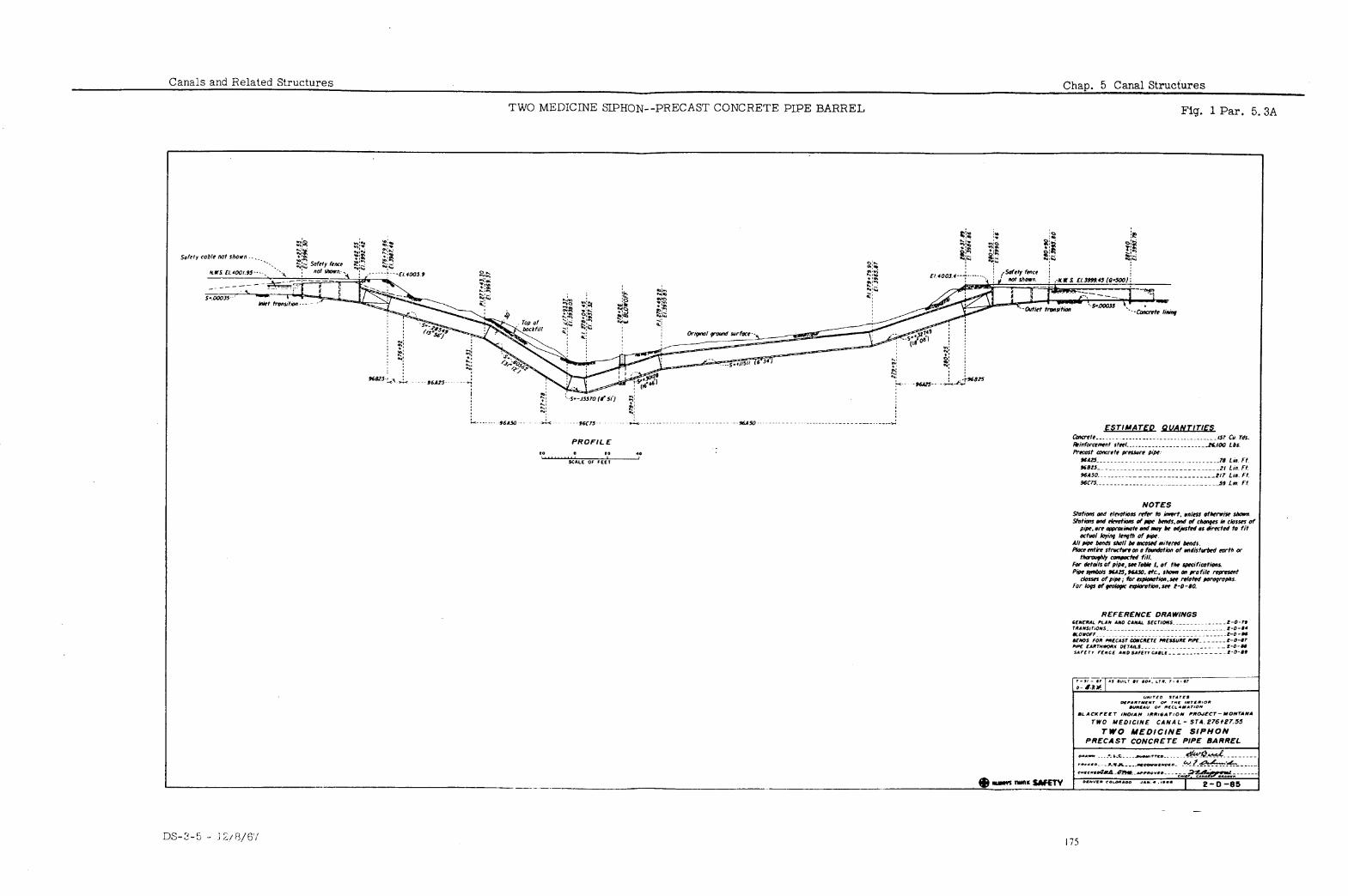
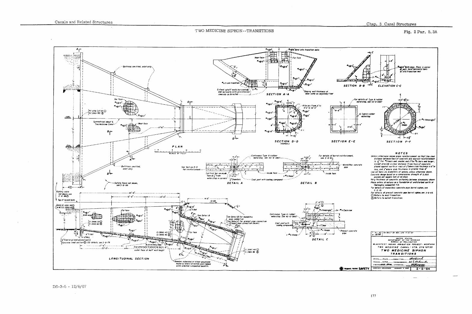
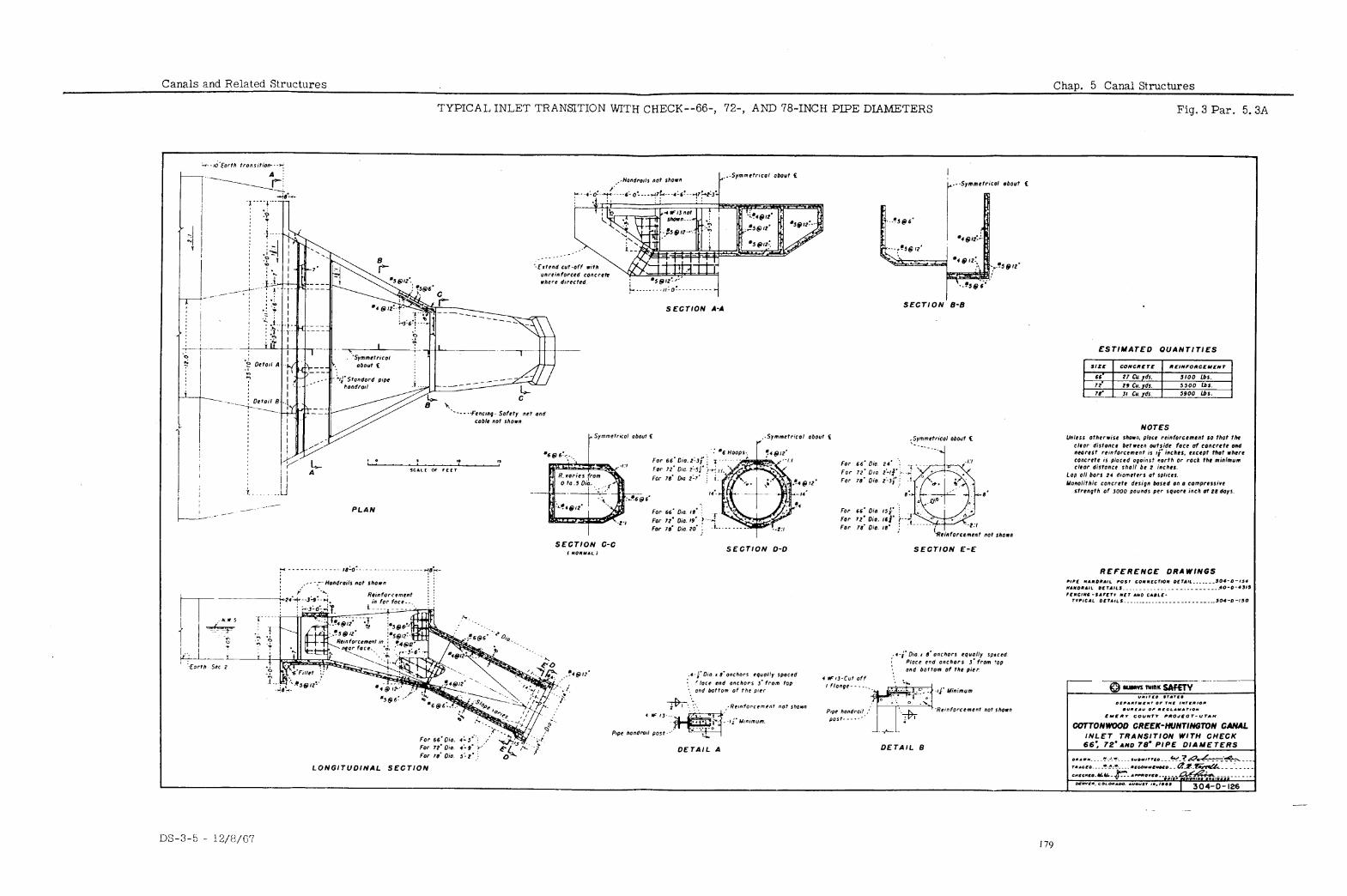
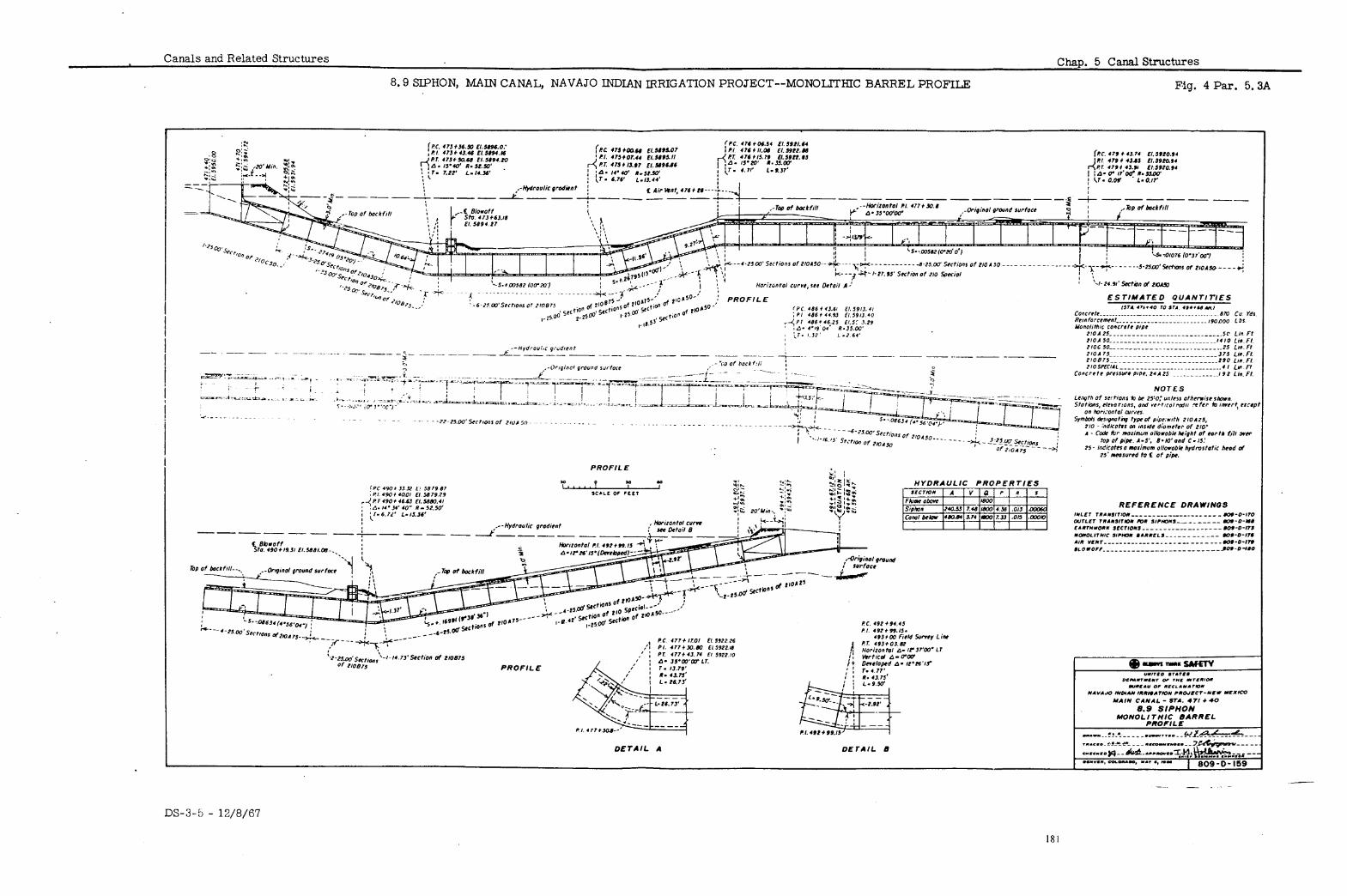
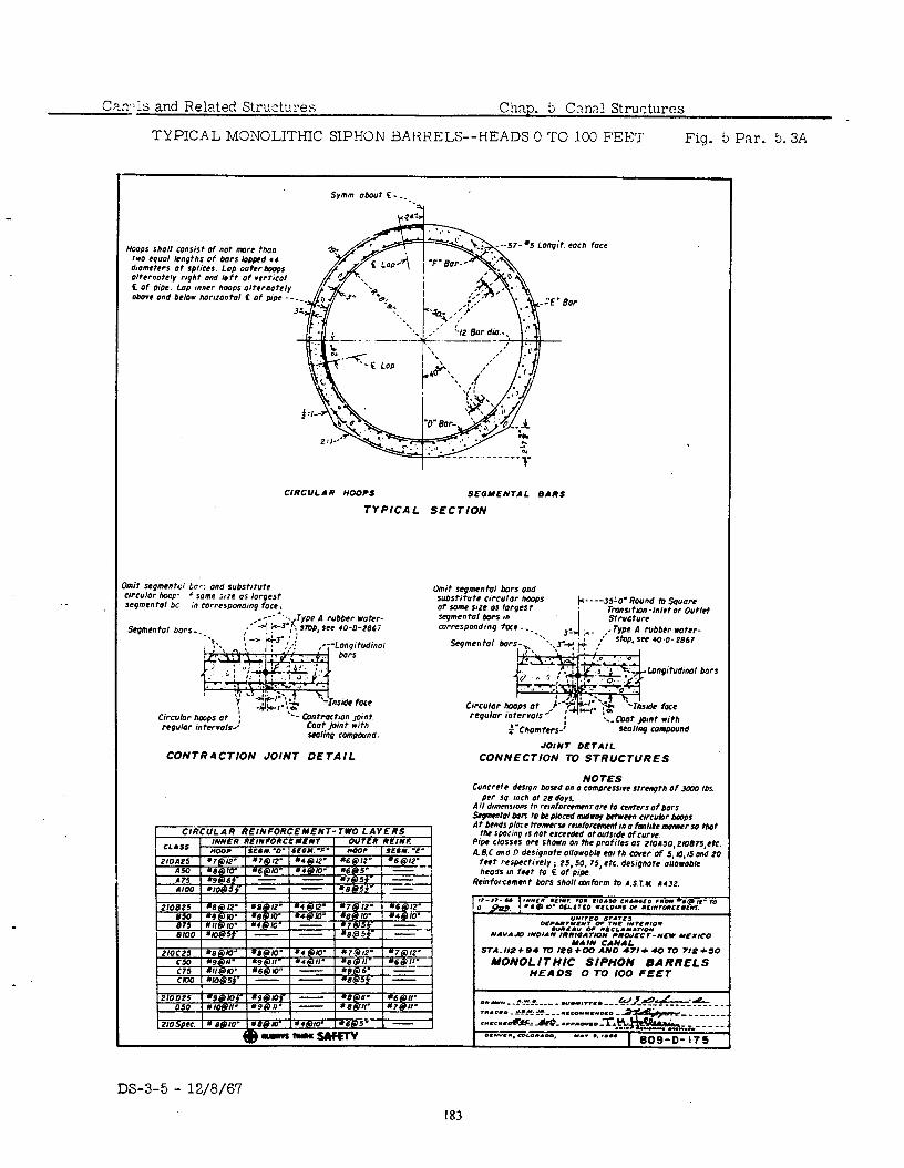
CaxIs and Related Structuxs Chap. ti Cnnn! Structures
TYPICAL M3NOLITHIC SIPHON BAilHELS--HEADS 0 TO 100 F’EE’I Fig. 5 Par. 5.3A
Symm obiwt S -__.
HOOPS shall consist of not more than two l quol len9ths of hors IoAAed .,
dromehrs ot splices. Lop outer hops olternotely rr9ht and bft of rerticol c Of pipe. Lop mncr hoops ortematcly above ond below horrzontol t of p,Oe --
57- =S Loqit. each face
,
ClRCUl. AR tlO0P.s SEGMENTAL 8ARS
TYPICAL SECTION
Omit se9ment0, bars ond substitute cwculor hops Of sonle sue OS 10r9es t segmental bars m mrrespondinp fae . _ _. . Type A rubber water-
SfOP. S@2 .0-O- 2667
Circular hmps ot : n9ulor intervals.’
‘-- tontPOCtlOn Joint Coot pint with Ml;09 rOmpO”“d.
rcpulor intervals -. ; I--’ I
faChomfers-’
::- mot jo,“, w;th seolin9 mmpoond
JOINT OEtAlL CONTR4CTION JOINT DETAIL CONNECTION TO STRUCTURES
NOTES COncrete drsqn hosed On 0 cOm~rcSS‘vc Strcnpth of 3m Ibs
PM SO inch at 78 days. All d#mens#onS tn rrmfOmmmt ore to enters of hors sqmentol bofx to be PlOced mdwoy b+tween clrcubr hoops At bends PIOX WQDIC~Y remforcaxent #” 0 fmmhke mener So Mot .
~0 on me profi7;i~i~~iso,zroe75,Otc. A. RC and fl desipnote OllowobC 001 th cover of 5.10.15 and 70
feet respectivt’ly ; 15,50. 75,ch. desipnote orio&ble heads m feet to E of pipe
i?einforcement hors Shall cmform to A S.1.y 4132.
-.n0* acc7-~cl YEXCO
NAL 0 *?I+ 40 70 718 l GO
DS-3-5 - 12/8/67
183
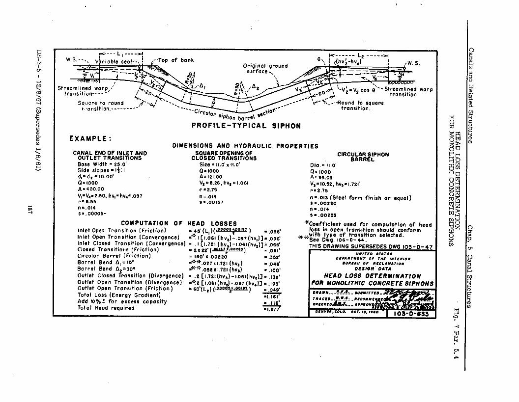
w.s.--., Vbrioble seal--, ! ,--Top of bonk 8, K----m- L
<(h”;-h”*)* --e--w
-.. I rw. s
warp
PROFILE-TYPICAL SIPHON
EXAMPLE : DIMENSIONS AN0 HYDRAULIC PROPERTIES
CANAL END OF INLET AND SQUARE OPENING OF OUTLET TRANSITIONS CLOSED TRANSITIONS
CIRCgU~~lt~;PHON
Bose Width = 26.0’ Side slopes = 14 : I
Size - 11.0’~ 11.0’ Q= 1000
d,=d, = 10.00’ A= 121.00
Q=1000 V,=6.26, hvs= I.061
A = 400.00 rr2.76
V,=V,=2.50, hv,=hv,-.os7 n = .ol4 r= 6.55 s = .00167 nr.014 s =. 00005-
COMPUTATION OF HEAD LOSSES Inlet Open Tronsition (Friction) =$(Ll)(~=22$22=) = .036’ inlet Open Tronsition (Convergence) =“:I Cl.061 (hv,)-.ost(hv,)]= .096’ Inlet Closed Transition (Convergence) = .I Cl.721 (hvs)-i.oGl(hvs)]k 966’ Closed Transitions (Friction) Circular Barrel (Friction)
I 2 w 22’ (WI57 l .0055e)
= 160’ X .0022ot Barrel Send &,=iSO =‘:-++.027 x I.721 (hv,) Barrel Bend iI,=? =‘-‘~.osexl.721 (hvs) Outlet Closed Transition (Divergence) = .2 [I.721 (hv,) -1.061( hvs)] = .132’ Outlet Open Transition (Divergence) Outlet Open Tronsition (Friction )
=*2 [i.o61(hvJ-,097 (hv,)] = .ts$
Total Loss (Energy Grodient) - 60’( L,) (-!=)
Add lo%? for excess capacity
Dio.=‘li.o’ 0 = 1000 A= ss.03 V,=10.52, hv,=t.721’ r=2.75
n=.Ol6 (Steel form finish or equal) s =.00220 nr.014 s = .00255
-‘Coefficient used for computation of head loss in open tronsition should conform
*+wlth type of transition selected. See Dwg. lob-o- 44.
DCCANrYCNT Of TN&? IN7CNlON #UNCAU Of NCCLANATION
OESlbN OATA HEAD LOSS OEtERMlNAflON
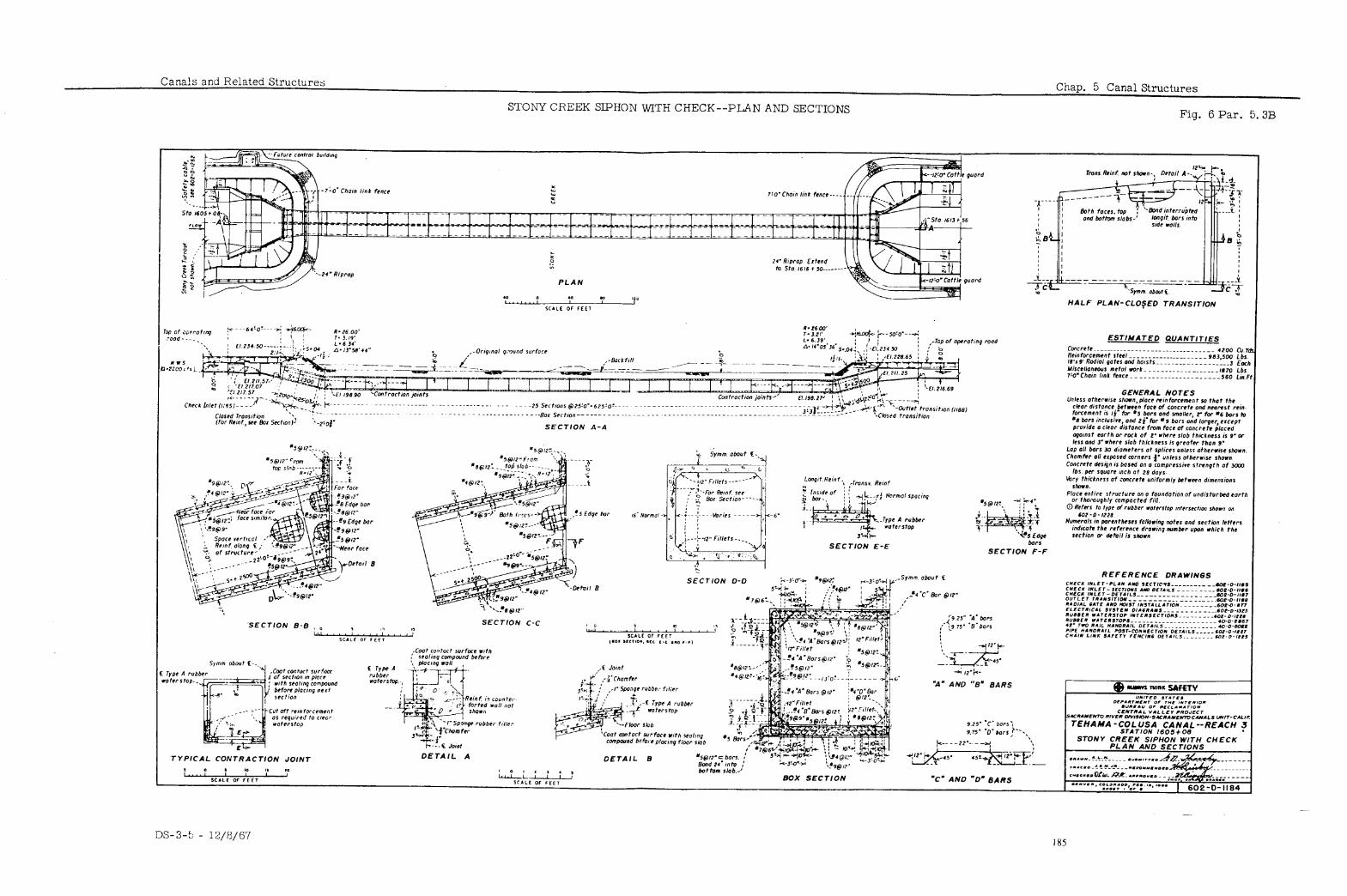
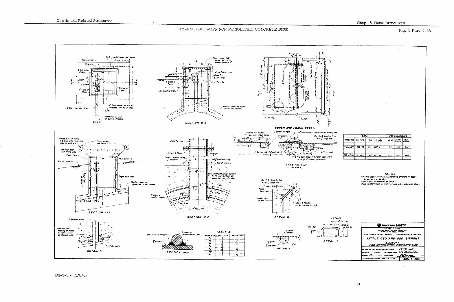
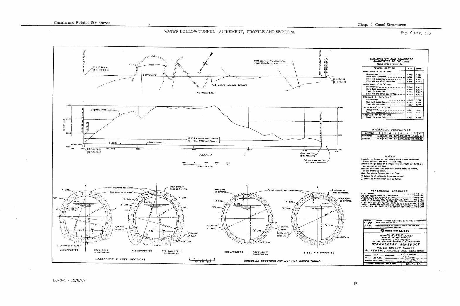
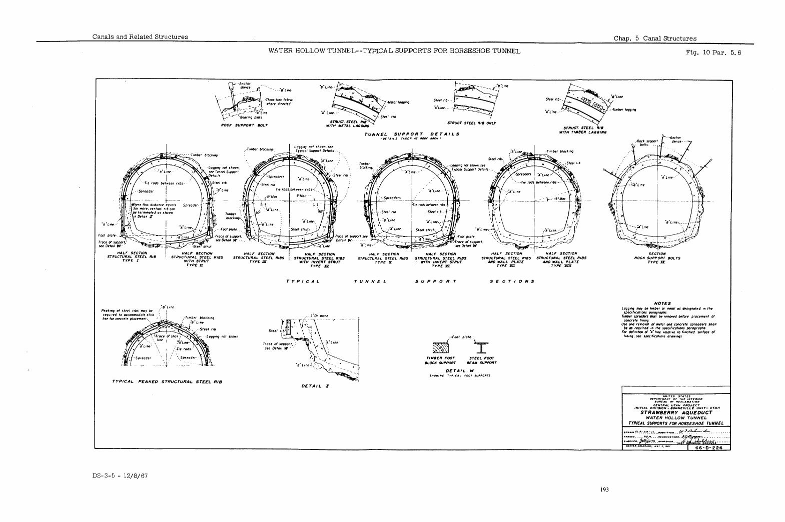
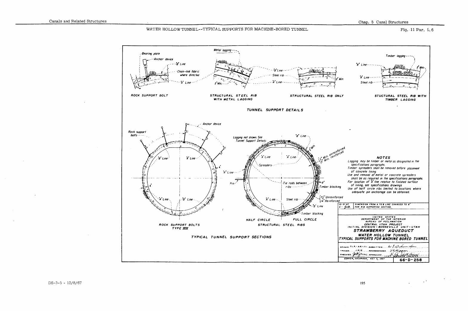
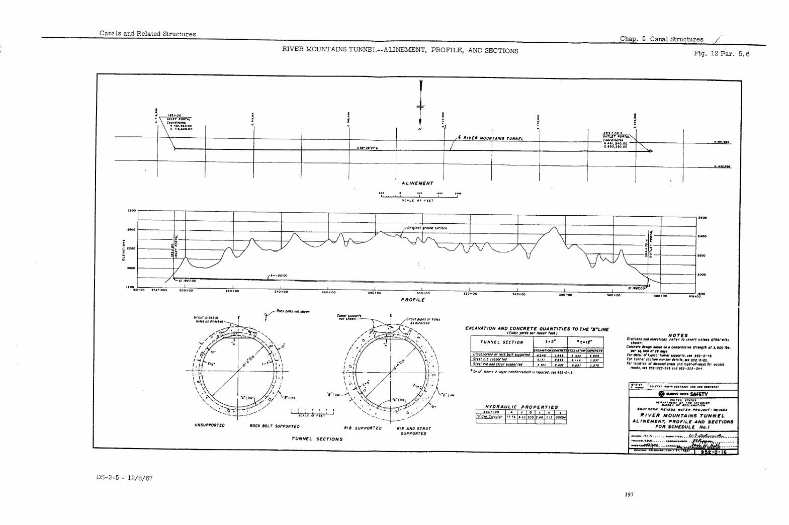
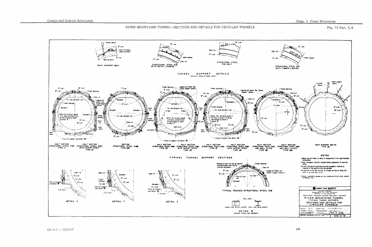
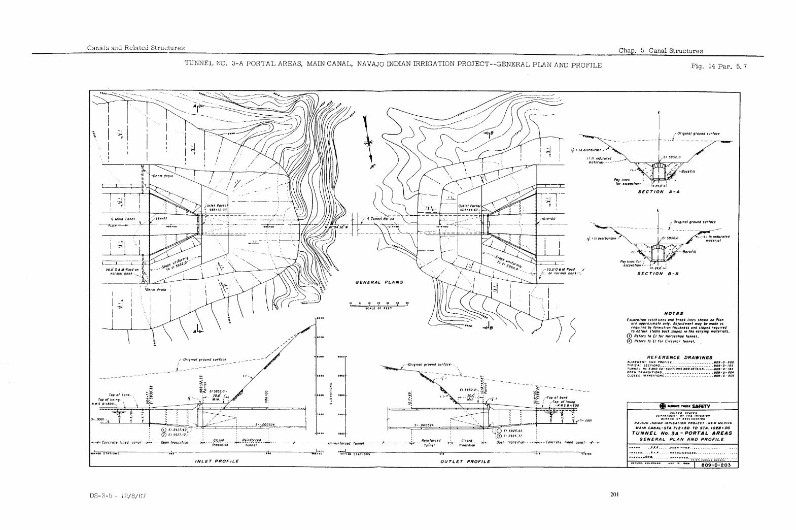
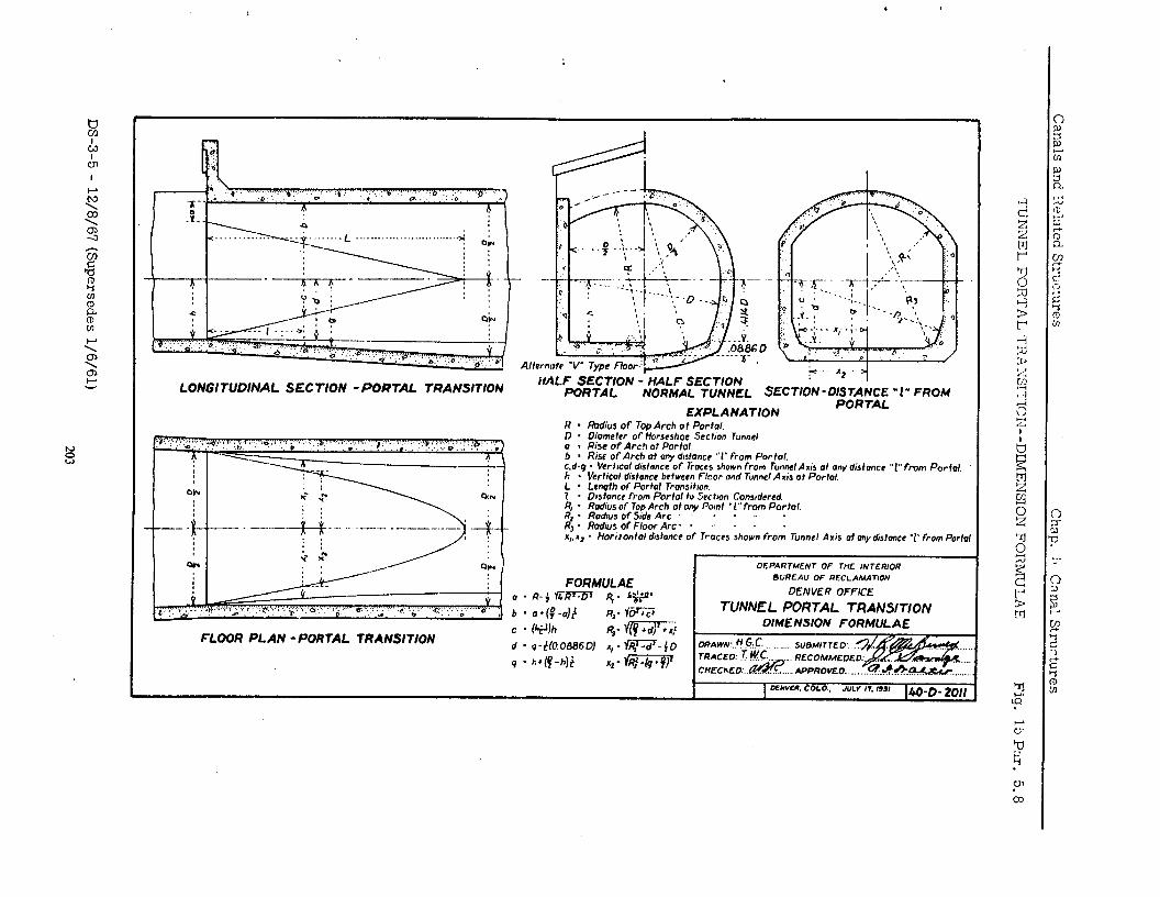
LONGlTUDlNAL SECTION -PORTAL TRANSlTlON itALF~~fKJT[ON - HALF SECTION NORMAL TUNNEL SECTION-O;;;;;; “2” FROM
EXPLANATION
DEPARTMENT OF THE INTERIOR BUREAU OF RECLAMATION
DENVER OFFICE
TUNNEL PORTAL TRANSITION
c - (+Jh R,. fli: r OIMENSION FORMULAE
FLOOR PLAN -PORTAL TRANSITION d - q-t%?O686Dl A,-JR:-d’-jD
q - h+(f-h)t 12-w&T Clmm:..~.l1 APPROVED.. . . . . .
0EY”W. COLO.. JULV r7.1931 /w-o. to,,
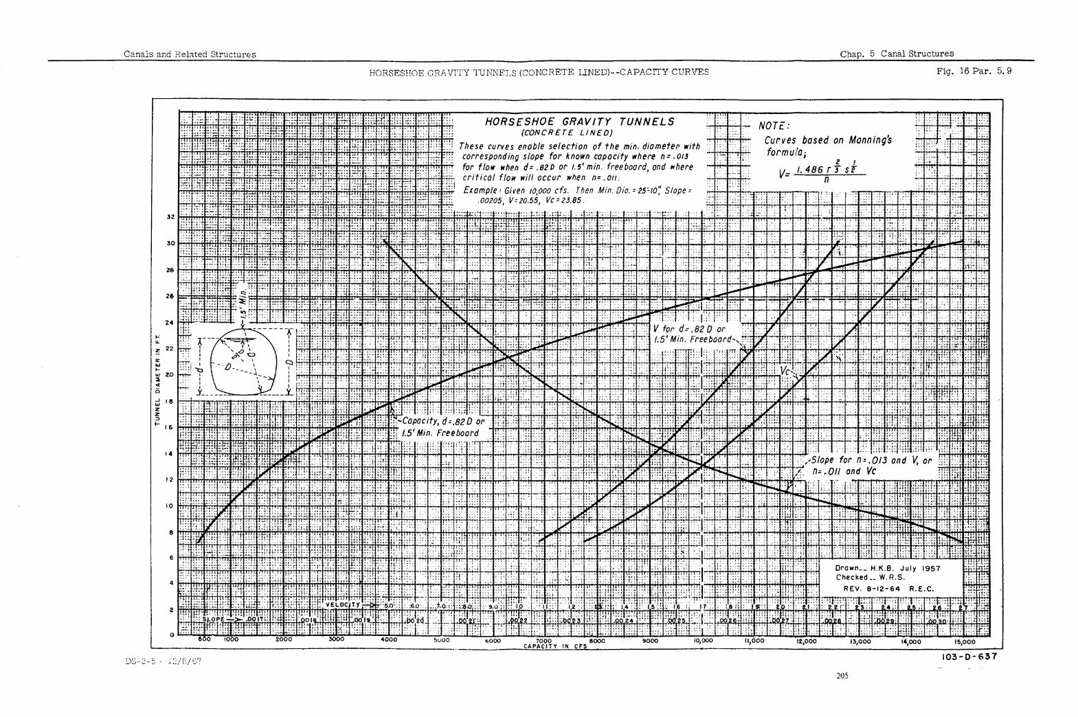
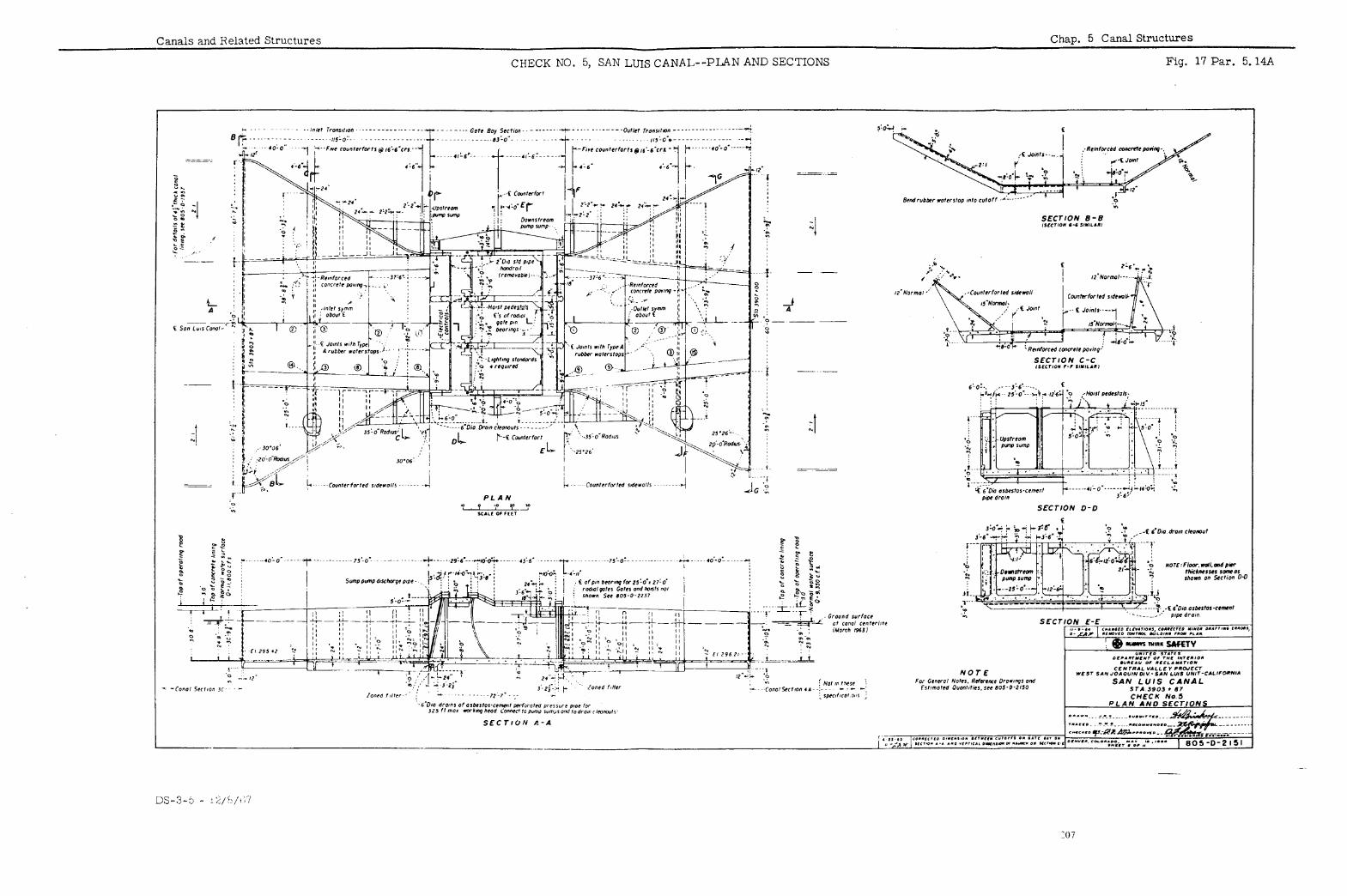
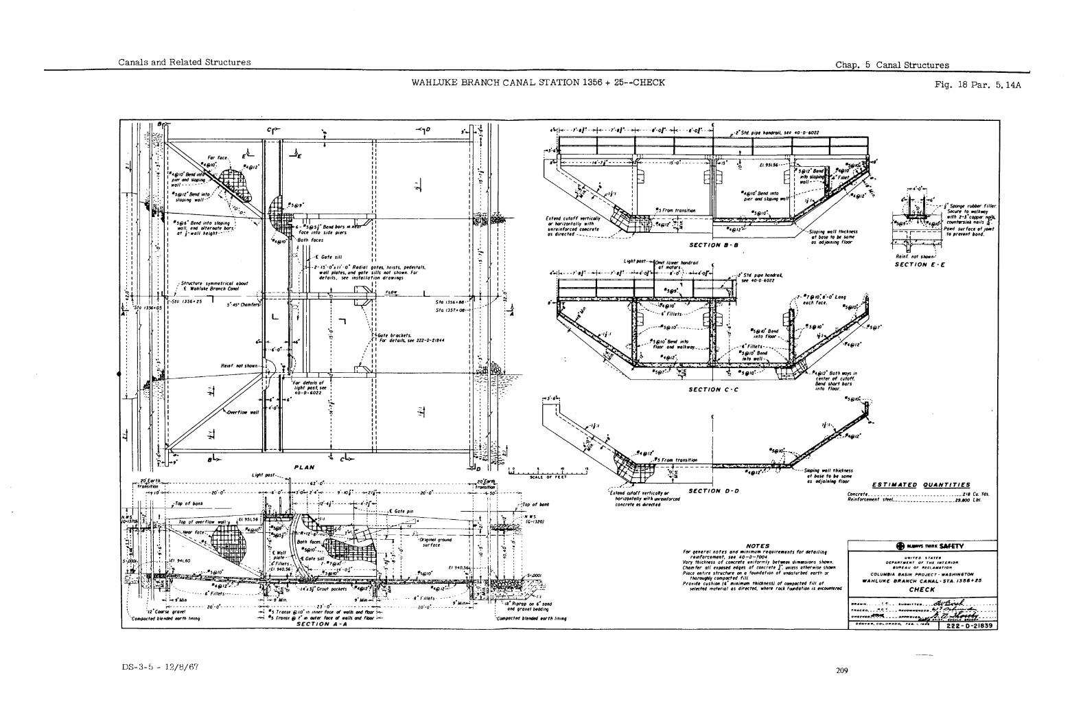
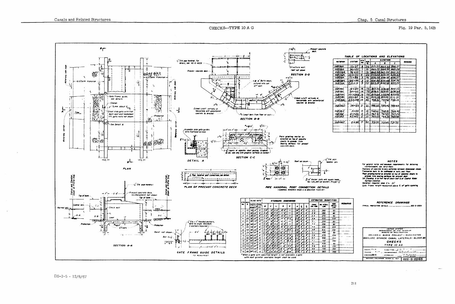
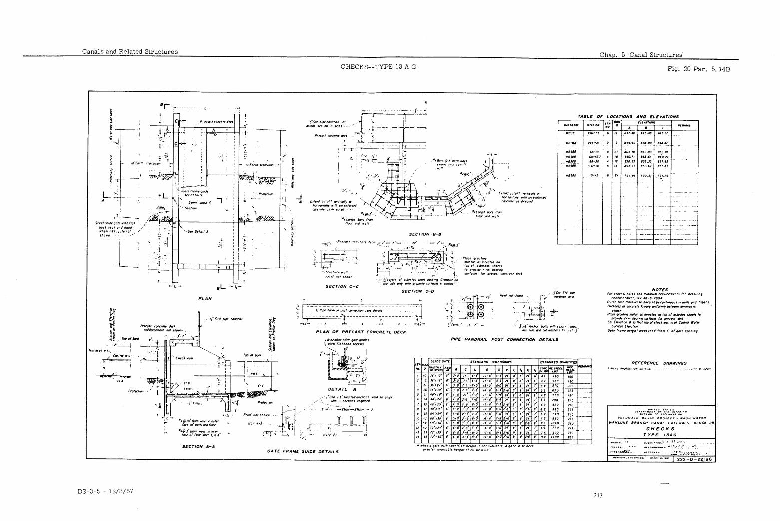
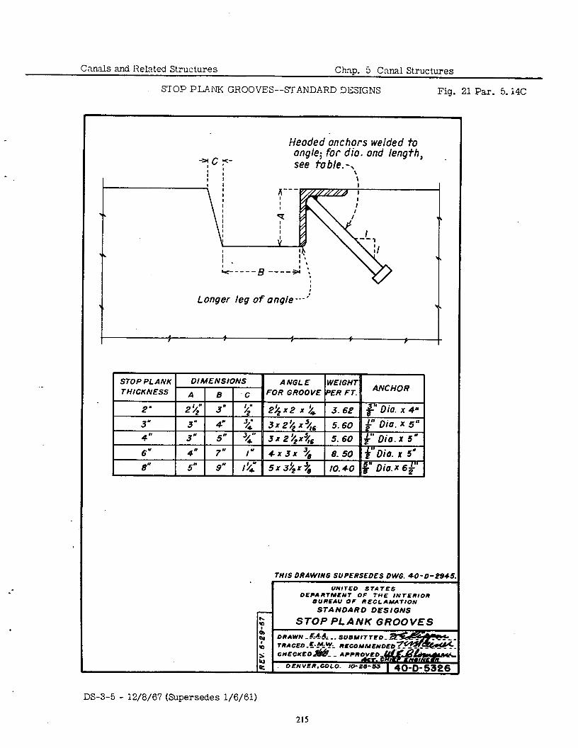
Cnnnls and Related Structures Chnp. 5 Cnnal Structures
STOP PLANK GROOVES--STANDARD DESIGNS Fig. 21 Par. 5.14C
.
Heodedkxhors welded to angle; for dio. and length, see table.-,
\
I ANCHOR
THIS DRAWING SUPERSEDES DWG. 4D-D-P94S.
UNITE0 STATES OEPARTHENT OF THE INTERIOR
BUREAU OF RECLINATION STANDARD DESIGNS
STOP PLANK GROOVES ORAWN -!%*& __ SIJSNITTEO-
DS-3-5 - 12/8/67 (Supersedes l/6/61)
215
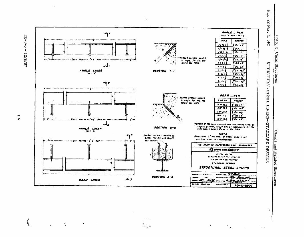
~..,L& . . . . . . . . _ _..... -..,rqcr*, Ipoe@) - ,‘-I’ mo# . . . . . . _._ -....-._.----_. &..3!.-Lj
J <I
ANSLE LINER r*,t -4’
“I’ p . ..-___ _ ..-. * --....-.-.--.------ _-__-.- L _ -.-.-- _ ~~-~~-~-.--~~~.--~..~~-... d
J UP ANOL E LINER ,l.. ‘..
SECTION I-I
‘--ttWdCd anchors rrldrd 10 On@H. For dia ond ICn9tl) III toblr.
SEAM LINER
S@C TION I! - C
*drams of IAl some nomrnol SIIC and honnp cquol or str9htl 9rqokr wrrpht may bc substrtutrd for the
I wtdr lonpr broms shown #n thr toblc.
_-_ -....-......-. EquO, rpocr* _ I’.,’ mot. ----..-.._..___......
Dimensions ‘1. ond sizes of tincrs 9wcn m me porc~orr order oc spccrfrcotrons.
I’it l rA*oAI)O OC.I,IVI
STRUCTURAL STEEL LINERS
” --.. __._ ---.- __ .------. _ -_----__-_- ‘ ._._._.--. _ ..______._________________ 4 SECTION S-s
bEAM LINER
, . 6 ‘\ ..,,,. t,., . 4
t
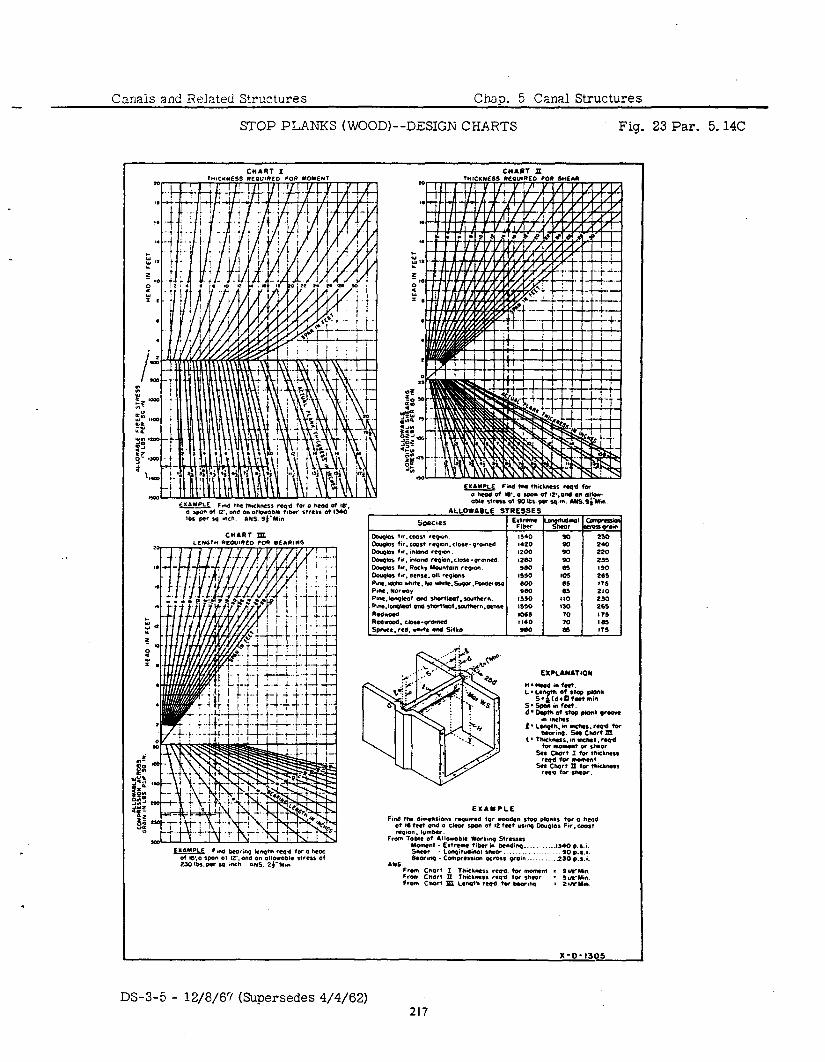
Canais and Relzted Structures Chap. 5 Canal Structures
STOP PLANKS (WOOD)--DESIGN CHARTS Fig. 23 Par. 5.14C
. .
DS-3-5 - 12/8/67 (Supersedes 4/4/62)
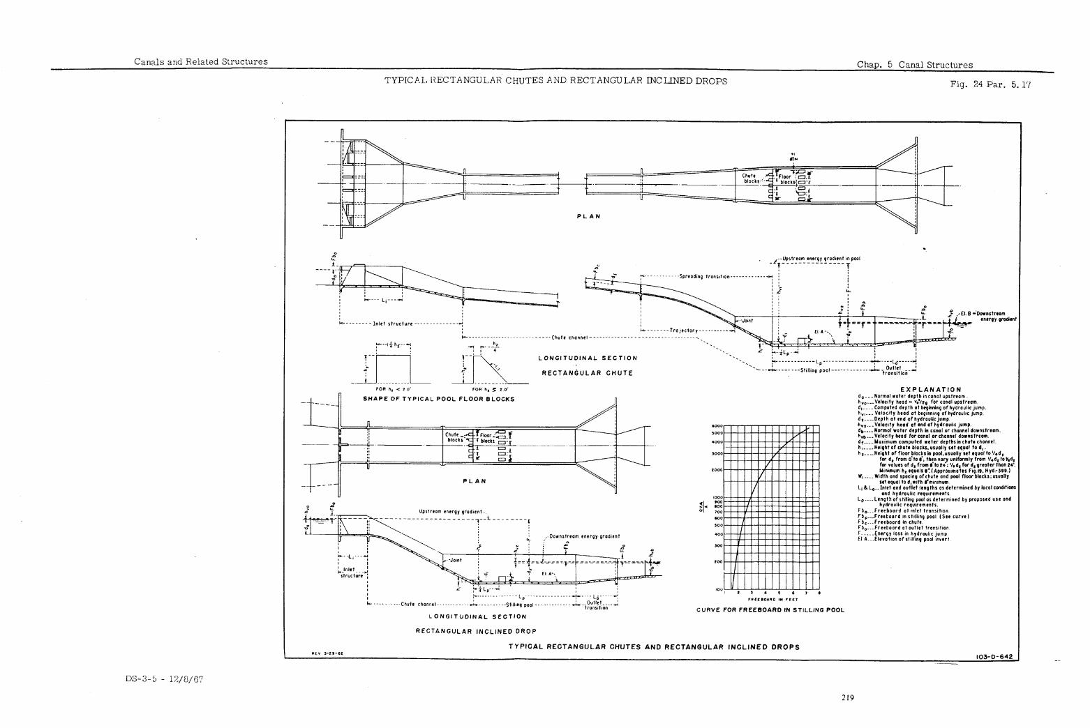
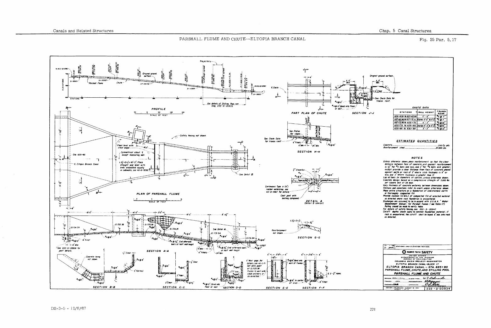
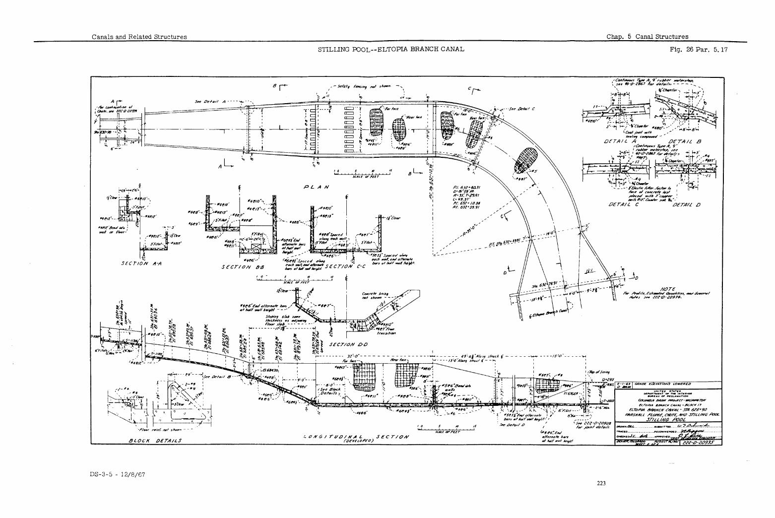
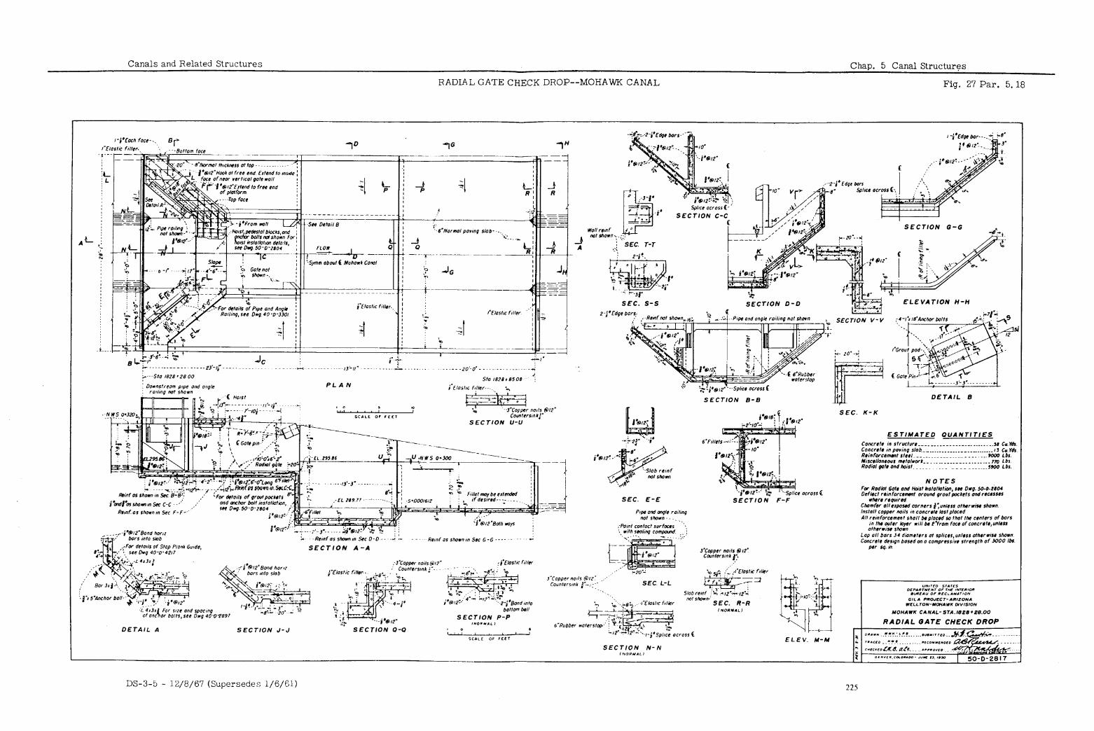
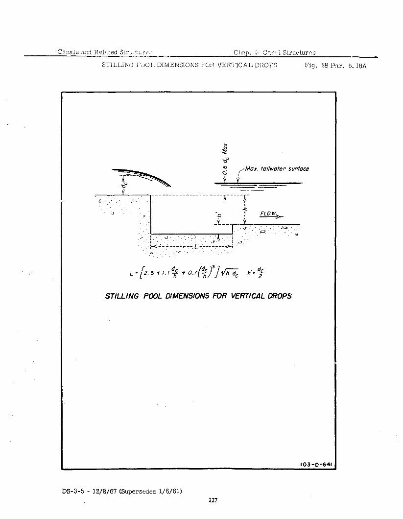
Fig. 28 Pm. 5.18A
.-
‘0 :, : .a., : .a’...
.’ :1: .a.- . ..* .‘. .. ..a
. ,. : .: ;;.d .‘i- .,I
I ‘4 “. ,;*-: I --.-,Ar+, L’++-r’r’-*
,‘o. ..‘.T’.‘. _‘.. :,_, . .
io.7 5; ( )I dc 3 fi h’= $ STILLING POOL DIMENSIONS FOR VERTICAL DROPS
103-O-641
EM-5 - 12/8/67 (Supersedes l/6/61) 227
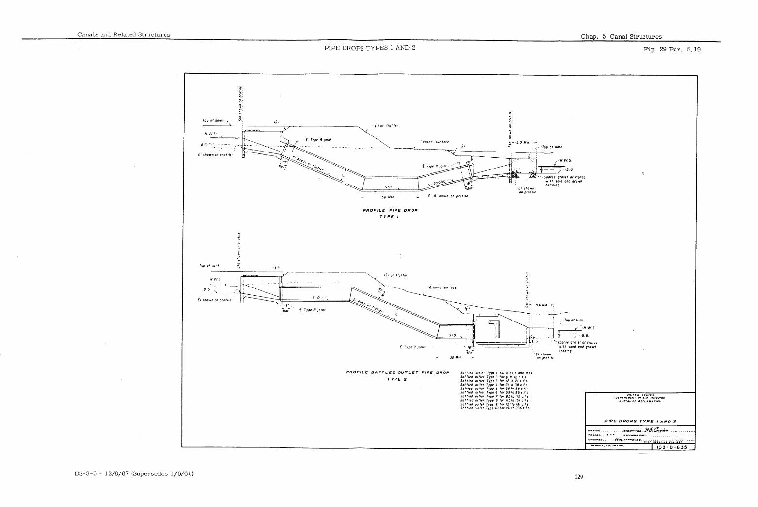
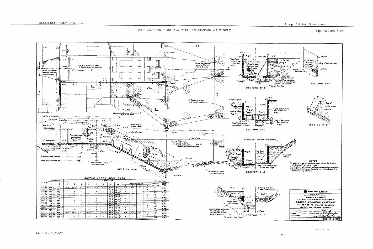
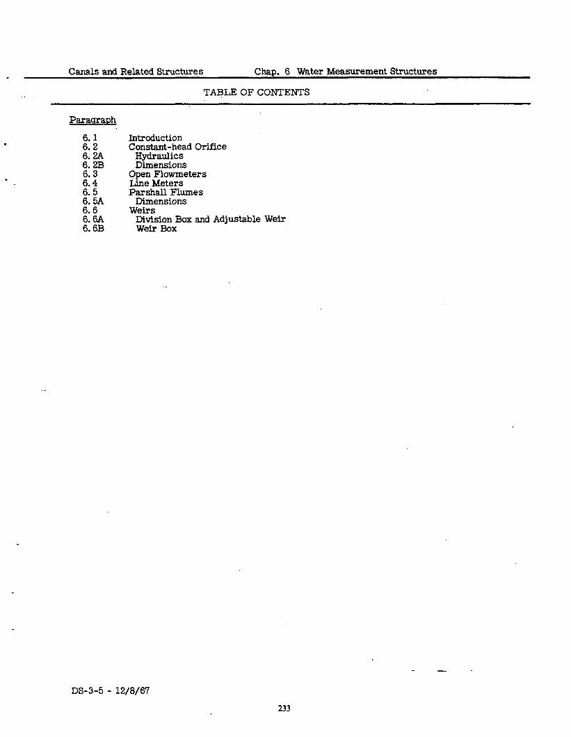
Canals and Related Structures Chap. 6 Water Measurement Structures
. TABLE OF CONTENTS
.
Introduction Constant-head Orifice
Hydraulics Dimensions
Open Flowmeters Line Meters Parshall Flumes
Dimensions Weirs
Division Box and Adjustable Weir Weir Box
. -
DS-3-5 - 12/8/67
233
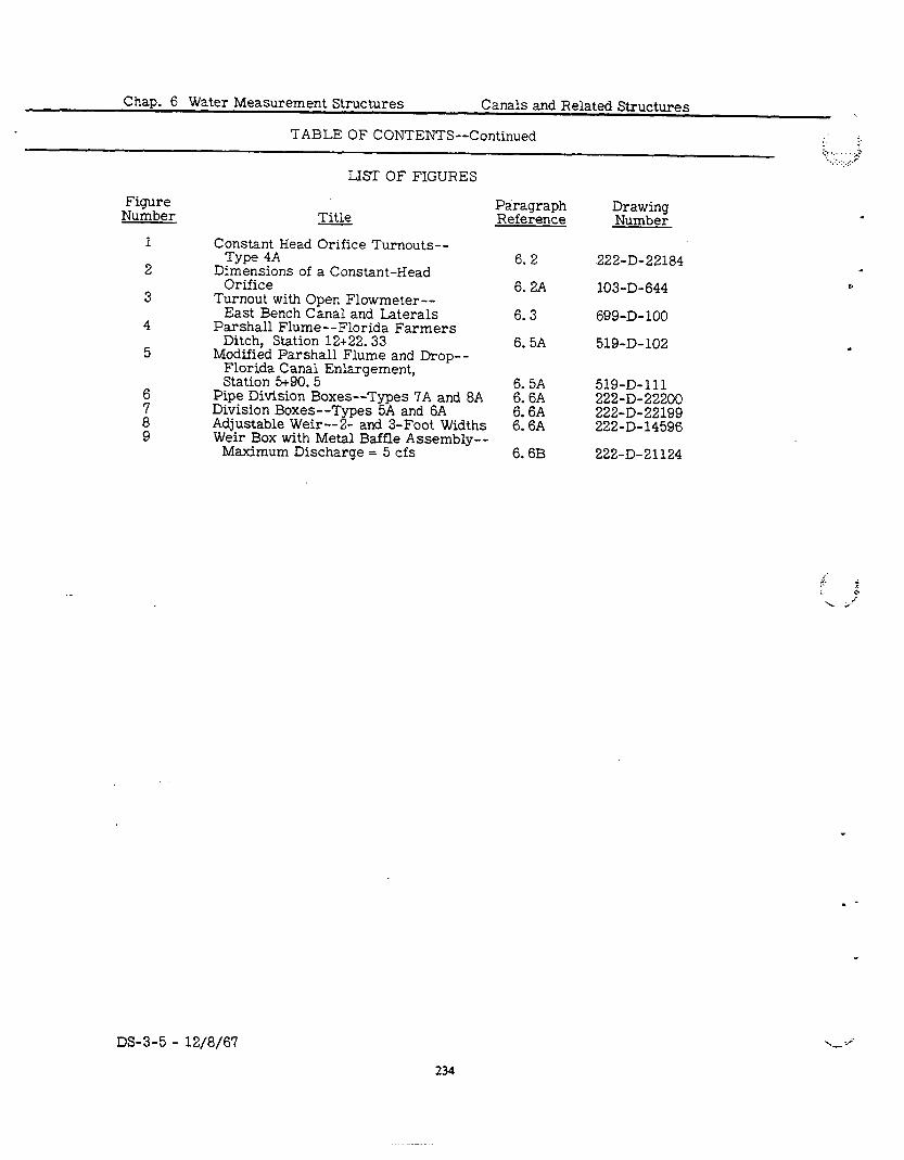
Chap. 6 Water Measurement Structures Canals and Related Structures
TABLE OF CONTENTS--Continued I <. . a c. ‘....; .:...d-
Figure Number
1
2
3
4
5
t 8 9
LIST OF FIGURES
Title Paragraph Reference
Drawing Number
Constant Head Orifice Turnouts-- Type 4A
Dimensions of a Constant-Head Orifice
6. 2
6. 2A Turnout with Open Flowmeter--
East Bench Canal and Laterals 6. 3 Parshall Flume--Florida Farmers
Ditch, Station 12+22.33 6. 5A Modified Parshall Flume and Drop--
Florida Canal Enlargement, Station 5+90. 5 6. 5A
Pipe Division Boxes--Types 7A and 8A Division Boxes--Types 5A and 6A ;-El Adjustable Weir--2- and 3-Foot Widths 6: 6A Weir Box with Metal Baffle Assembly--
Maximum Discharge = 5 cfs 6.6B
222-D-22184
103-D-644
699-D-100
519-D-102 l
519-D-111 222-D-22200 222-D-22199 222-D-14596
222-D-21124
DS-3-5 - 12/8/6’7
234
.
Canals and Related Structures Chap. 6 Water Measurement Structures
6. 1
.1 This chapter contains design information for the more commonly used water INTRODUCTION measurement structures in canals and laterals. They are constant-head orifice structures, open flowmeters, line meters, Parshall flumes, and weirs. General structural and hydraulic design criteria relating to water measurement structures are given in Chapter 2. In the structural drawings selected for illustration, there may be instances in which current design practices differ in some respects from those illustrated.
.2 Constant-head orifice structures are often used in turnouts where sufficient CONSTANT- head is available between canal and lateral or farm delivery water surfaces. HEAD Two gates are required for satisfactory operation. The first gate controls ORIFICE the area of the orifice and the second gate controls the water depth below the orifice. A constant difference in head on the two sides of the orifice gate is maintained by adjusting the downstream gate. The amount of water pass- ing is determined by the size of the orifice set by the first gate with a definite differential head. This type of structure may also be used for water meas- urement on an in-line structure. These structures, called orifice measuring devices, may be operated by’varying the differential head if properly cali- brated. Figure 1 shows a constant-head orifice turnout structure of a type that has been constructed a+.many locations. The following criteria are for capacities up to 30 cfs with 0.2-foot differential head. Special consideration should be given for greater capacities and other differential heads.
A. A value of C = 0.70 should be used for the orifice reinforcement at the bottom of the gate leaf. A ae of C = 0.65 should
te with angle-iron
be used where the angle-iron reinforcement is not provided. A value of C = 0. ‘75 should be used for the turnout or second gate. When the orifice gate is set for maximum capacity, the bottom of the gate leaf must ex- tend below the breast wall a distance equal to or greater than the nominal thickness of the breast wall. Where accuracies better than & 7 percent are required, careful field ratings of the turnout must be made.
For good accuracy with discharges as shown in the table or computed by the orifice equation, the upstream submergence must be equal to or greater than the gate opening for maximum capacity. reduces the accuracy and calibration is required.
Less submergence The top of the turnout
gate opening must be below the water surface in the measuring box by at least 1.78 times the velocity head of the full pipe plus 3 inches.
The above seals are required for accurate water measurement. Where the constant-head orifice is used as a turnout with closed conduit, the conduit and outlet should be treated the same as a siphon or pipe drop depending on the local conditions. An air vent as shown on Figure I must be provided wherever the delivery water surface at aqy flow is such that a vacuum can develop downstream of the control gate. Dimensions for a constant-head orifice are shown in Figure 2.
B. For accurate measurement, a level floor must be provided in front of the orifice gate, of a length equal to or greater than the height of the orifice aate ooeninu for full caoacitv. The inside minimum 1enut.h of the
Hydraulics
Dimensions
measurhg bok shoad be at leak 2:1/4 times the orifice gate opening for maximum capacity or l-3/4 times the wall opening, whichever is
1”91 for turnouts with maximum capacities up to 10 cfs, and 2-3/4 times ?- height of the orifice gate opening at maximum capacity for structures with maximum capacities above 10 cfs. The inlet walls should be parallel unless extra width is needed at the inlet cutoff to prevent it from being a control in which case extra width may be obtained by flaring the walls, customarily 8: 1.
The distance between the inlet cutoff and orifice gate should be a mini- mum of l-1/2 times the difference in elevation between the invert at the
DS-3-5 - 12/B/67 235
Chap. 6 Water Measurement Structures Canals and Related Structures
OPEN FLOW-
METERS
PARSHALL FLUMES
Dimensions
.3
1.
cutoff and at the orifice gate. In an earth canal, the top of the sloping inlet walls should intersect the canal sideslope at or a few inches above normal water surface. The wet walls are usually sloped steeper than the canal sideslope and set back into the bank so they will not be out in the canal if it is widened at the bqttom during cleanin
all or reshaping.
The following tabulation shows recommended inlet w slopes corres- ponding to various canal sideslopes.
Canal sideslom
2-l/2:1
l-l,Iii
Inlet wall sloDe .
1-1,;;: 1 -l/2: 1 set into
the bank 12 to 24 inches depend- ing on size of canal and local conditions
Open flowmeters are propeller devices generally used at the discharge ends of closed conduits where rate of flow and totalization recording are desired, or where a minimum head loss is required. Water carrying considerable sediment or trash can cause trouble with these meters. Therefore, trash- racks ape sometimes provided at the upstream end of the conduit to prevent fouling of the meter. Open flowmeters may be attached to the outlet transi- tion headwsll on turnouts, siphons, and similar structures. The outlet transi- tion must be designed to force the conduit to flow full at the meter location. The desirable velocity in the conduit is from 1 to 8 feet per second for accu- rate measurement with the open flowmeter. Most meters operate satisfac- torily with velocities down to l/2 foot per second. Also, the accuracy of the meter is not affected by velocities higher than 8 feet per second, but the life of the standard meter bearings is reduced to the extent that excessive repair and maintenance will result. A special heavy-duty meter can be obtained for higher velocities, in which case velocities up to 13 feet per second have been allowed. A mimmum of 6 diameters of straight, level conduit must be pro- vided immediately upstream from the meter .location unless straightening vanes are used. Figure 3 shows a typical turnout with an open flowmeter in the outlet transition.
.4 Line meters are propeller devices which operate on the same principle as open flowmeters. They are generally installed in a pipeline with a well to the ground surface to protect the recorder. meters and can usually be neglected.
Hydraulic losses are minor for
.5 Parshall flumes can be designed for measurement of small to large flows; Parshall’s tables were prepared for capacities up to 3,300 cfs through a 50-foot-wide flume. Since the velocity through the structure is higher than that in the adjacent channel, waterborne sand and silt will not deposit in the structure to affect the accuracy, which is ordinarily within 5 percent.
A. Measurement of discharge through a Parshall flhme is based on coeffi- cients determined by experiments. The hydraulic design procedure must follow the rules and dimensions in Colorado State College Bulletins No. 386 or No. 426-A “Parshall Flumes of Large S&e” and No. 423 “The Parshdll Measuring Flume. I’ Parshall’s tables can be used where the structure is designed with a converging upstream section and level floor, a downward sloping throat, and an upward sloping section diverg- ing downstream with all dimensions in accordance with the above bulle- tins. The Bureau’s Water Measurement Manual also contains discharge tables for Parshall flumes. Modified Parshall flumes have often been
.
DS-3-5 -‘ 12/8/67 236
Canals and Related Structures Chap. 6 Water Measurement Structures
6.6
used without the upward sloping section diverging downstream, where an outlet transition or stilling pool has been provided. Calibration of these flumes is required to.determine their performance.
A straight channel of sufficient length to provide uniform flow must be provided upstream of the Parshall flume. If the structure is to be placed upstream of a reach of canal where the bottom may build up due to sedi- ment or where a checked water surface affects the flow, care must be taken to prevent submergence which could make the structure inoperative. Figure 4 shows details of a 185-cfs Parshall flume, and Figure 5 shows details of a modified Parshall flume and drop.
.6 The use of weirs is limited to locations where adequate head is available. Although other types of weirs have been developed, the Cipolletti and rectan- gular weirs are generally used. The Bureau’s Hydraulic and Excavation Tables and the Manual for Measurement of Irrigation Water contain tables giving the discharge for various weirs. The accuracy is reduced if the up- stream pool is not maintained, if the head on the weir is greater than one- third the weir length, or if the depth over the weir is less than 0.2 foot. The velocity of approach should be small, or corrections for the approach veloc- ity and other factors made as described in the reference tables. The weir crest should be sharp edged, and the stream over the weir should have free fall with admission of air under the stream.
WEIRS
A. Movable and adjustable Cipolletti weirs, which can be easily removed Division Box from the structure or adjusted vertically within a frame, provide a means of control in addition to measurement, and are often used in
and Adjustable Weir
division boxes on lateral systems. division boxes.
Figure 6 shows two types of pipe Figure 7 shows division boxes for an open lateral.
Figure 8 shows the adjustable weir.
B. Figure 9 shows the weir box. This structure is for a maximum discharge Weir Box of 5 cfs. Designs are also available for discharges to 10 cfs.
DS-3-5 - 12/8/67 237
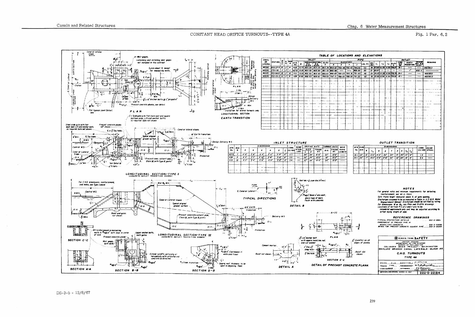
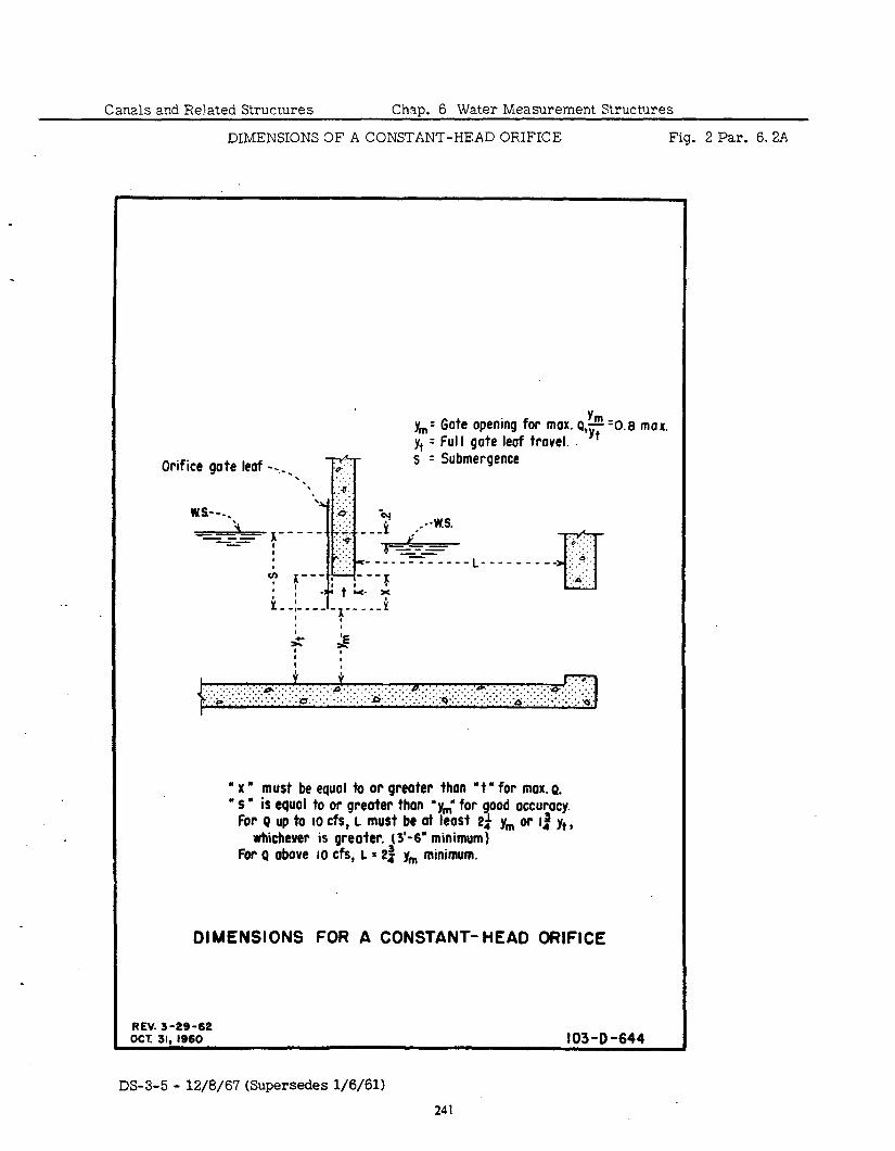
Canals and Related Structures Chap. 6 Water Measurement Structures
DIMENSIONS 3F A CONSTANT-HEAD ORIFICE Fig. 2 Par. 6.2A
.
.
Orifice gate leaf --_
y,,,= Gate opening for max. Q,~+ &=0.8 n y+ - Full gote leaf trovel.
-l?r s’ = Submergence
II L ;; e ‘.” ------ :. ------L ---__
f --- ?-+I- --K 1 1 -‘tL + -,- --- - !-----y k I a , I
--- :& .: :. ::: _ 11.9’.
ET : +:::: ..’
’ x” must be equal to or greoter than *t * for max. Q. * S * is equal to or greater than ‘y,’ for good accuracy.
For Q up to IO cfs, L must be at least 2i y,,, or 14 y+, whichever is greater. (3'-6" minimum)
For Q above 10 cfs, L = 23 y,,, minimum.
DIMENSIONS FOR A CONSTANT- HEAD ORIFICE
REV. 3-29-62 OCT. 31, IS60 103-D -644
DS-3-5 - 12/8/67 (Supersedes l/6/61)
241
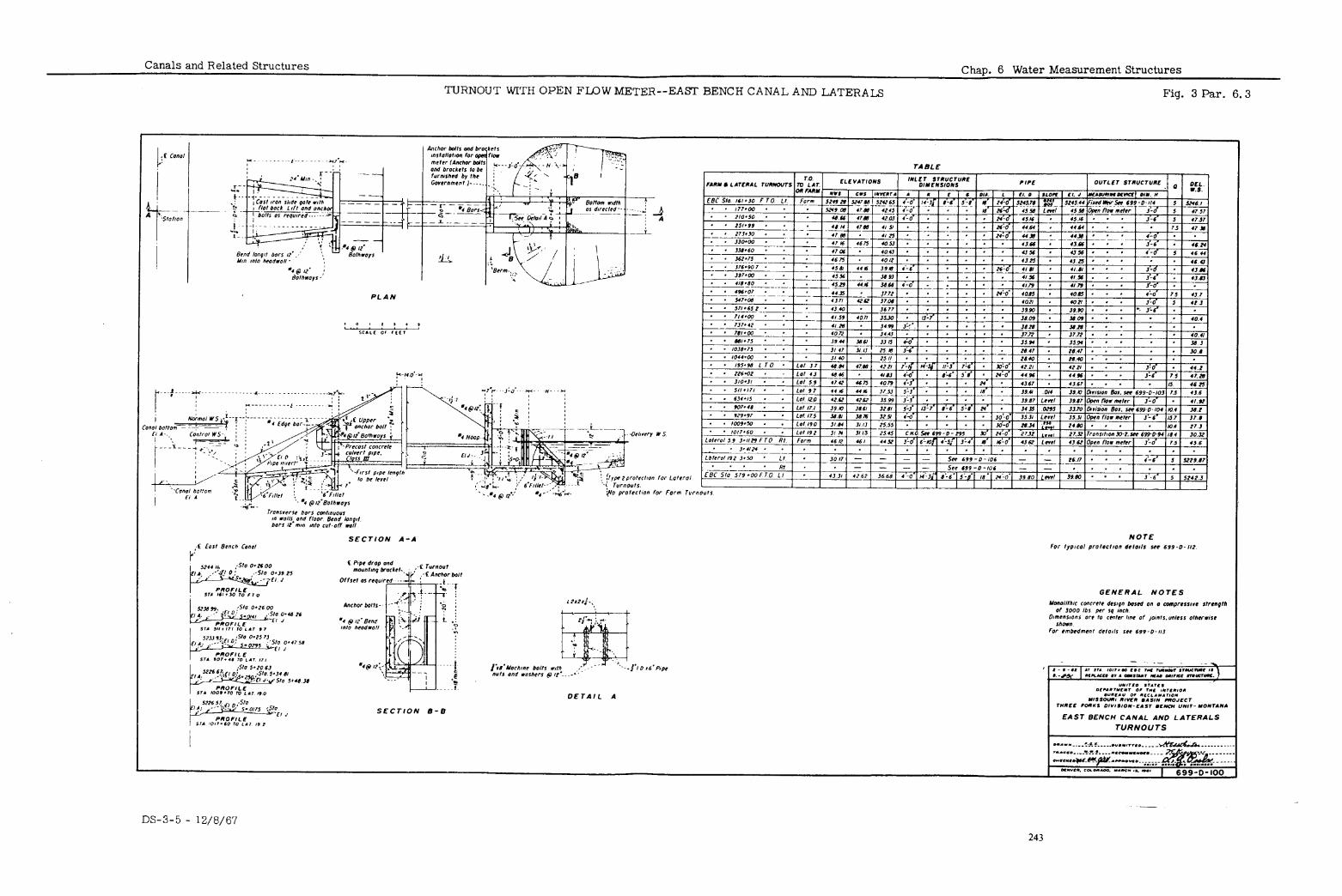
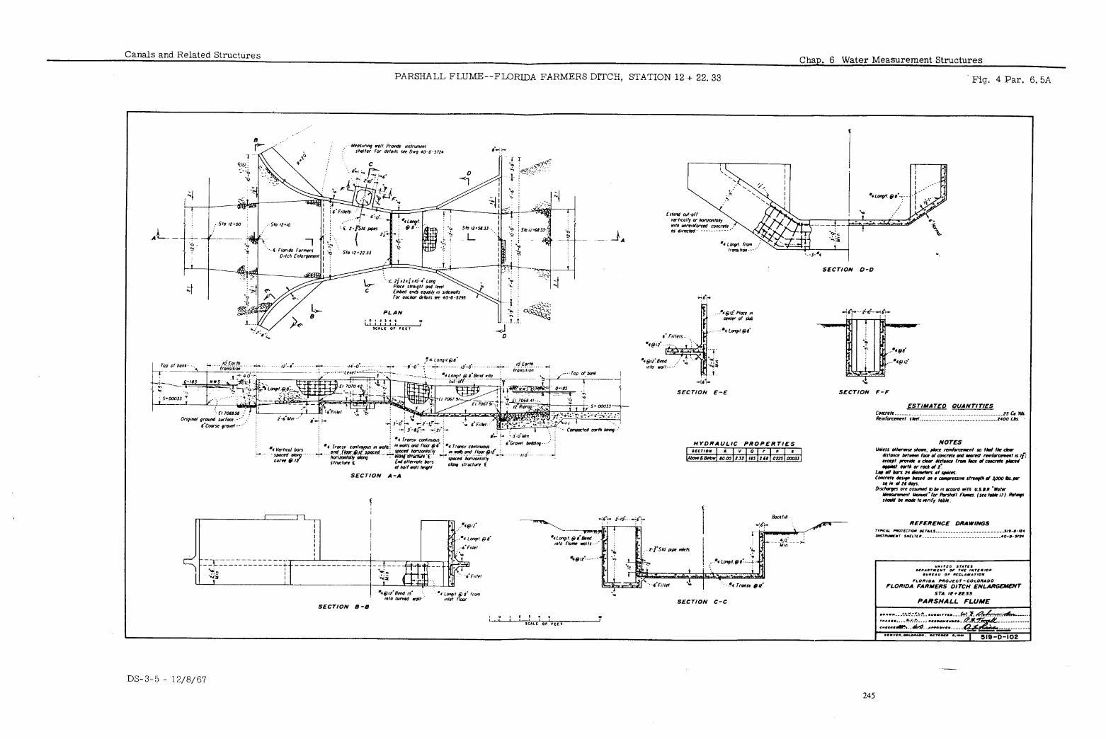
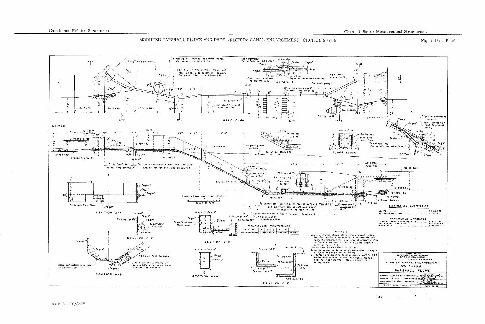
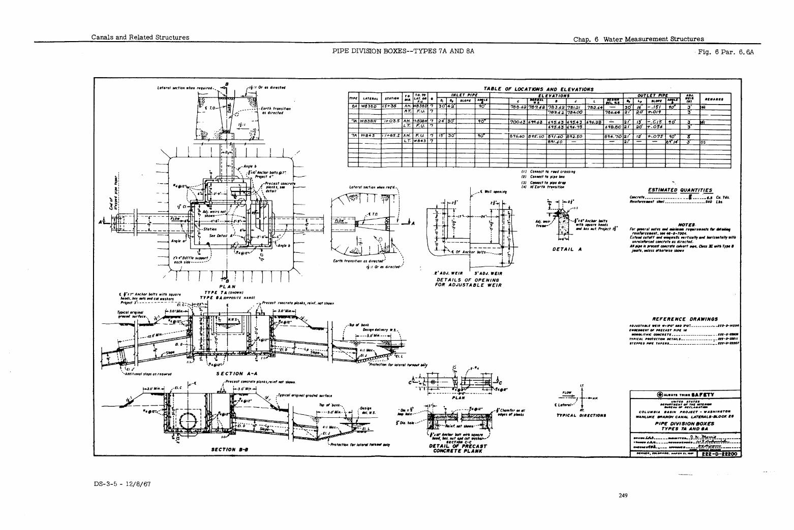
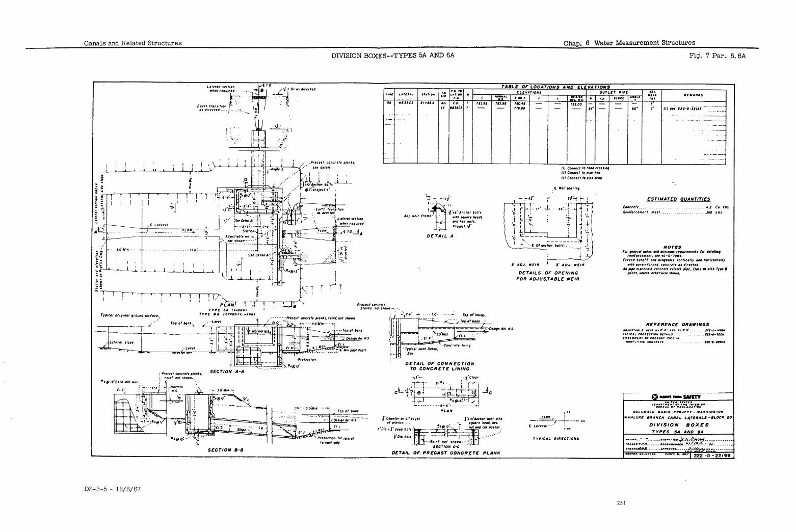
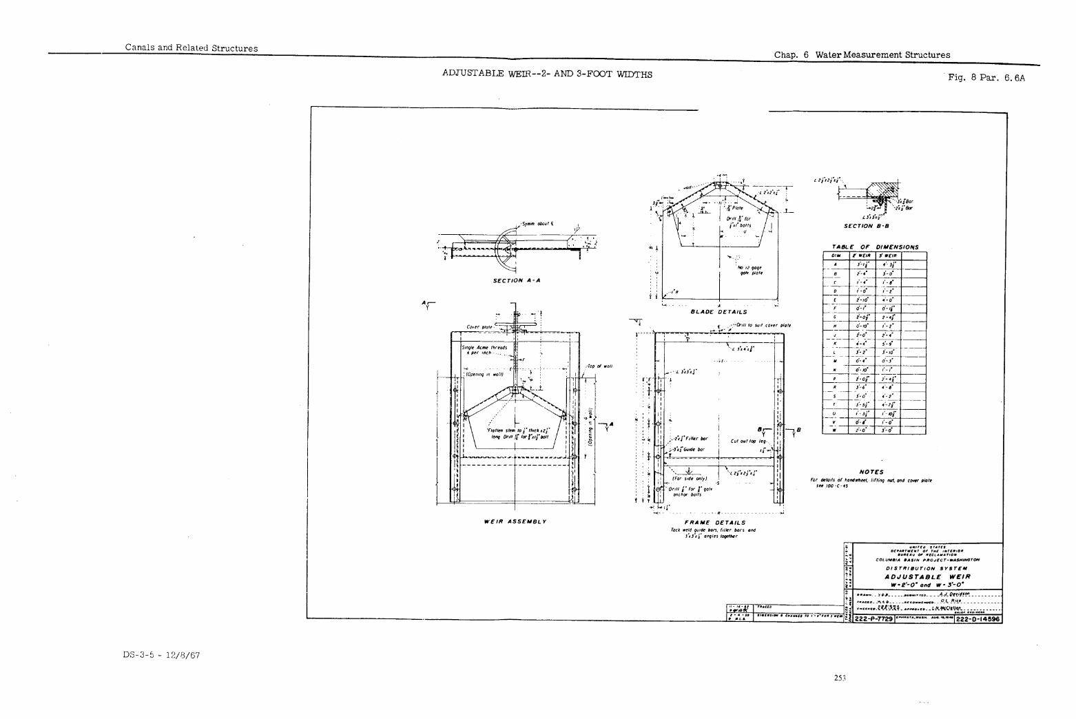
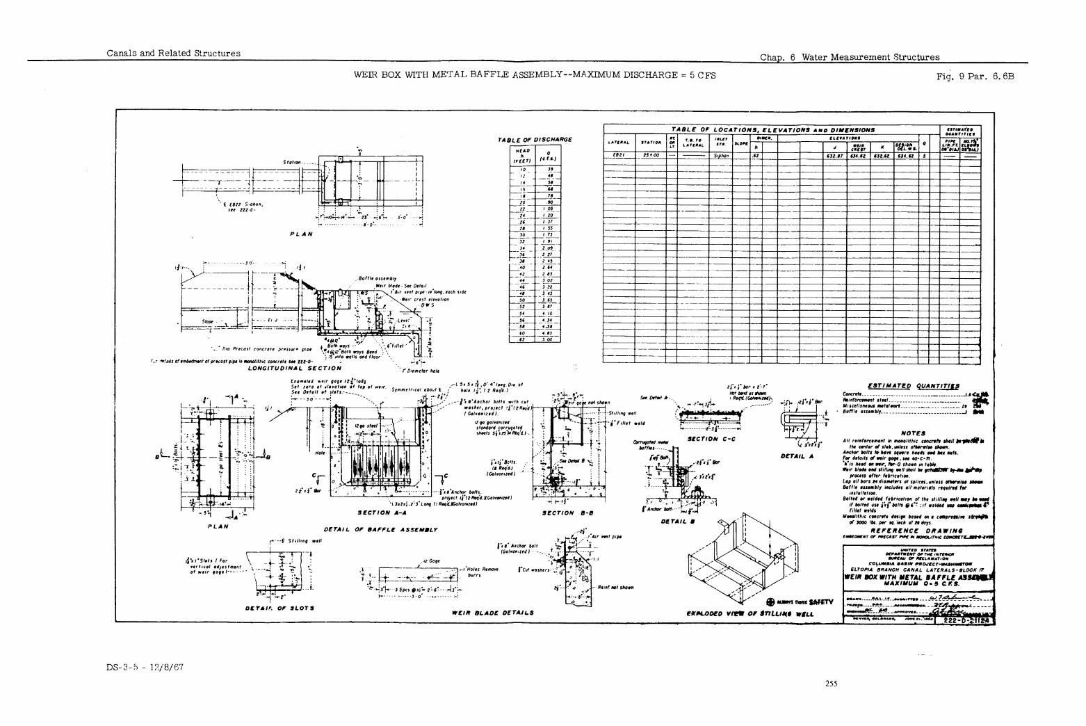
Canals and Related Structures Chap. 7 Cross Drainage and Protective Structures
TABLE OF CONTEXTS
Paraqraph
Introduction Culverts
Inlet Outlet
Overchutes Drain Inlets Spillways
Overflow Spillway Radial-gate Spillway Siphon Spillway
Wasteways .
DS-3-5 - 12/8/67
257
Chap. 7 Cross Drainage and Canals and Related Structures Protective Structures
TABLE OF CONTENTS--Continued
,-*
LIST OF FIGURES
Figure Number Title
1 Concrete Pipe Culverts-- West Canal Laterals
2 Overchute--Putah South Canal, Station 1534+80
3 Irrigation Crossings--Florida
4 Farmers Ditch Enlargement
Wasteway Plan and Sections-- .
5
6
Osborne Canal, Station 443+00 Wasteway Inlet Details--
Osborne Canal, Station 443+00 Typical Low- head Siphon
Spillway- -Design Data
Paragraph Reference
Drawing Number
7. 2
7.3
7.3
7. 5
7.5
7.5c
222-D-21331
413-D-576
519-D-118
468-D-330
468-D-331
103-D-46
--
DS-3-5 - 12/8/67 .:
‘b ..v -
258
Canals and Related Structures Chap. 7 Cross Drainage and Protective Structures
7.1
.1 This chapter contains design information for structures that convey storm or drainage water under, over, or into canals; also structures that provide
INTRODUCTION
controlled discharge of excess water from the canal for safety of operation. General structural and hydraulic design criteria relating to cross drainage and protective structures are given in Chapter 2. In the structural drawings selected for illustration, there may be instances in which current design practices differ in some respects from those illustrated.
.2 Culverts are structures that carry flood or drainage water under canals, lat- erals, roads and railroads.
CULVERTS Various shapes and materials have been used in
culverts, but the most common are single- or multiple-barrel precast con- crete pipe and rectangular monolithic concrete conduits. Adequate cutoffs, at least one on each side of the canal, should be provided to prevent percolat- ing water from following the conduit and causing washouts. Where the cul- vert barrel passes under an earth canal, the top of the barrel should be at least 24 inches below the canal invert. Where the culvert barrel passes under a lined cana& a clear distance of 3 inches should be allowed between the bar- rel and the lining. In determining the minimum size of a culvert carrying floodwater, the quantity of flow which will be produced by a 25-year frequency flood, divided by a velocity of 10 feet per second, should be used to obtain the area required, except that if a baffled outlet is provided a velocity of 12 feet
.
per second may be used. With the minimum size so determined, selection of the magnitude of storm for which the culvert is designed should take into con- sideration the local hazards involved such as the effect of ponding above the canal, the possibility of damage from water discharged from the culvert, and the overall damaging effect of possible structure failure. diameter of 24 inches is usually set for use on a project.
A minimum culvert The size will de-
pend on the damage that plugging might cause and on the type of debris ex- gAytifrrF the drainage area. Figure 1 shows typical pipe culverts with
.
A. Inlets may consist of the plain end of the culvert pipe, a straight or bent headwall, or various types of concrete transitions.
Inlet The inlet should be
determined on the basis of existing conditions. It must permit the design flow to enter the culvert with adequate freeboard for canal protection. This freeooard is normally 2 feet or more for the design flood. The in- let invert should be located near the existing ground surface or at the bottom grade of an inlet channel, if provided, to prevent degradation above the culvert. If the conduit slope is steep and the outlet water sur- face low, the capacity of the culvert will be controlled by the inlet. In this case the depth of ponding above the canal will be determined from the control at the inlet cutoff or the headwall, whichever governs. If the downstream water surface is high enough to make the conduit flow full, the hydraulics to determine the capacity and pondage should be computed on the basis of a submerged conduit with proper loss coefficient for the existing conditions.
B. The outlet should be designed to protect the structure against local scour. The safety of the outlet is also dependept on the stability of the down- stream channel. This waterway must resist gullying or the culvert may fail regardless of the outlet type. Baffled outlets or other types of energy dissipators should be used where it is required that adjacent facilities be protected from local scour. A level length of pipe equal to at least three pipe diameters is desirable at the inlet to baffled outlet structures; how- ever, slopes up to 15” have been permitted. Baffled outlets may be ob- jectionable if the culvert transports debris that might plug the structure.
Outlet
.3 An overchute is a structure that carries flood or drainage water across and above the canal prism. An overchute should be used where the cross drain-
OVER-
age gradient is sufficiently high to provide freeboard over the canal water CHUTES
DS-3-5 - 12/8/67
Chap. 7 Cross Drainage and Protective Structures
Canals and Related Structures
7. 4
OVER- CHUTES (Cont’d. )
surface without excessive ponding at the inlet. Rectangular concrete flume sections are generally used for large flows, while closed conduits are often used for small flows. Transverse ribs are sometimes provided on the flume floor of large structures to retain an insulating earth layer which will reduce the induced temperature stresses in the concrete floor and piers. shows an overchute with a stilling pool.
Figure 2 Figure 3 shows a steel pipe cross-
ing. The type of energy dissipator is selected for least cost to meet the re- quirements for the structure. control local scour.
The outlet must be designed to adequately The downstream channel must be sufficiently stable to
avoid erosion which might endanger the structure.
DRAIN INLETS
.4 Drain inlets are used to introduce small amounts of drainage water into the canal when an economical means of crossing the canal is not available. In general, it is more desirable and safer to carry flood and drainage water across the canal in culverts, in overchutes, or over canal siphons instead of permitting it to enter the canal, because of the operating problems, cleaning costs and other costs which are introduced by permitting storm and drainage water to enter the canal.
The maximum drainage inlet capacity at any point should not exceed 10 per- cent of the capacity of the cans!. unless evacuation facilities are provided immediately upstream from the point of storm water entry. In case large flows are taken into the canal, and a waste outlet is provided immediately upstream, some storm water will pass on down the canal because of the rise in water surface necessary to operate the waste facilities. This increased flow, plus all other water admitted to the canal during any given storm, must be evacuated before the accumulation endangers the banks or structures. The maximum allowable rise due to this incre+sed flow is usually equal to one- half the lining freeboard or one-fourth the bank freeboard, whichever is the least. The point of maximum water surface rise will be upstream of a struc- ture such as a siphon, and this will usually locate the wasteway. (See Para- graph 7.6.)
Water may be emptied into the canal through a rectan$ular concrete flume section or a closed conduit. In earth canals, a flume section usually requires a chute and pool to prevent eroding or damaging the canal, whereas a pipe can often discharge a small amount of water near the canal water surface without appreciable damage to the canal.
SPILLWAYS .5 Spillways are provided on canals to automatically remove some water from the canal when the water surface exceeds a set elevation. The spillway capac- ity should be adequate to empty flood and unused irrigation water and ttms pre- vent damage to the canal and appurtenant structures. If a spillway is used as protection for a powerplant or similar installation, it may be required to pass the entire capacity of the canal. Functionally, a spillway differs from a waste- way in that, while it may possibly discharge the entire flow, it cannot be used to empty the canal. The most common canal spillways are side-channel over- flow spillways, siphon spillways, and automatic radial-gate spillways. Waste- ways and spillways are often combined to provide a means of emptying the canal as well as controlling the water depth for protection. the use of a common outlet channel.
This also permits Figures 4 and 5 show a combined over-
flow spillway and wasteway.
Overflow Spillway
A. Overflow spillways may be used to empty weeds, trash, ice, and other floating objects, as well as excess water, from the canal. They are desirable where the exact amount of water to be emptied is not known, because a small additional head over a long overflow crest will consider- ably increase the discharge. However, the long overflow crest may be objectionable at some locations. Usually a wasteway gate can be com- bined with an overflow spillway without appreciable added expense for the structure.
.
DS-3-5 - 12/8/67 260
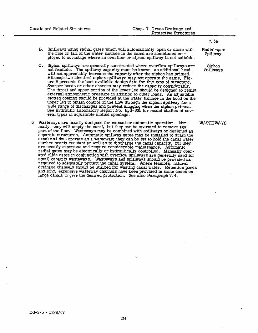
Canals and Related Structures Chap. 7 Cross Drainage and Protective Structures
B. Spillways using radial gates which will automatically open or close with the rise or fall of the water surface in the canal are sometimes em-
Radial-gate
ployed to advantage where an overflow or siphon spillway is not suitable. Spillway
C. Siphon spillways are generally constructed where overflow spillways are not feasible. The spillway capacity must be known, as additional head
Siphon
will not appreciably increase the capacity after the siphon has primed. Spillways
Although two identical siphon spillways may not operate the same, Fig- ure 6 presents the best available design data for this type of structure. Sharper bends or other changes may reduce the capacity considerably. The throat and upper portion of the lower leg should be designed to resist external atmospheric pressure in addition to other loads. An adjustable slotted opening should be provided at the water surface in the hood on the upper leg to obtain control of the flow through the siphon spillway for a wide range of discharges and prevent sluggin See Hydraulic Laboratory Report No. Hyd-33 %
when the siphon primes. for model studies of sev-
eral types of adjustable slotted openings.
.
.6 Wasteways are usually designed for manual or automatic operation. Nor- mally, they will empty the canal, but they can be operated to remove any part of the flow. Wasteways may be combined with spillways or designed as separate structures. Automatic spillway gates may be instaIled to drain the canal and thus operate as a wasteway; they can be set to hold the canal water surface nearly constant as well as to discharge the canal capacity, but they are usually expensive and require considerable maintenance. Automatic radial gates may be electrically or hydraulically controlled. Manually oper- ated slide gates in conjunction with overflow spillways are generally used for small capacity wasteways. Wasteways and spillways should be provided as required to adequately protect the canal system. Where feasible, natural drainage channels should be utilized for wasting canal water. Retention ponds and long, expensive wasteway channels have been provided in some cases on large canals to give the desired protection. See also Paragraph 7.4.
WASTE WAYS
DS-3-5 - 12/8/67 261
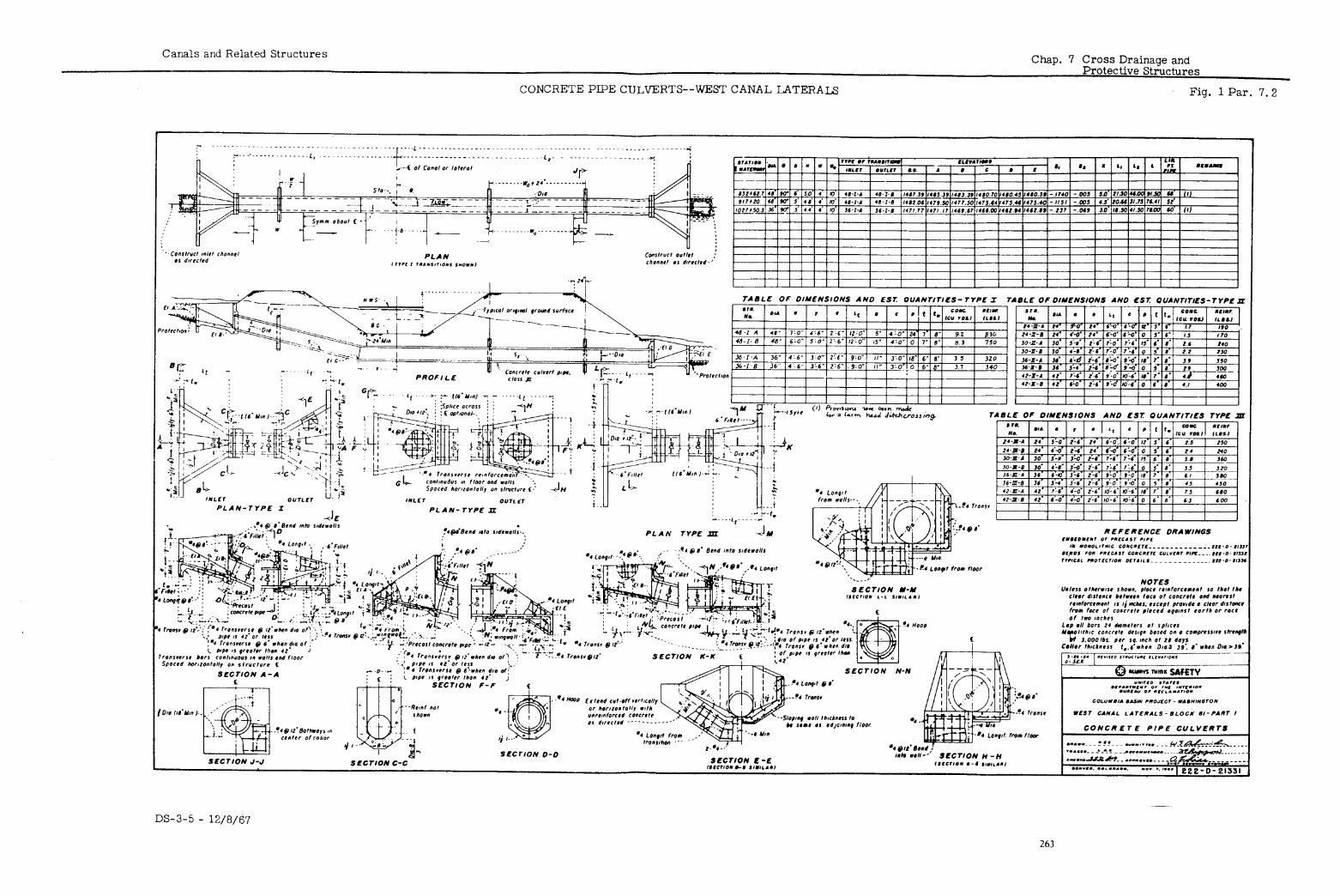
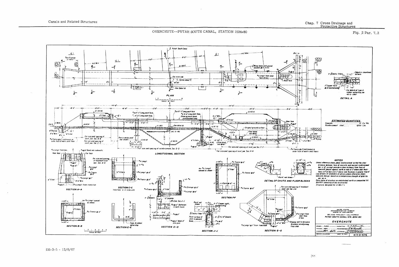
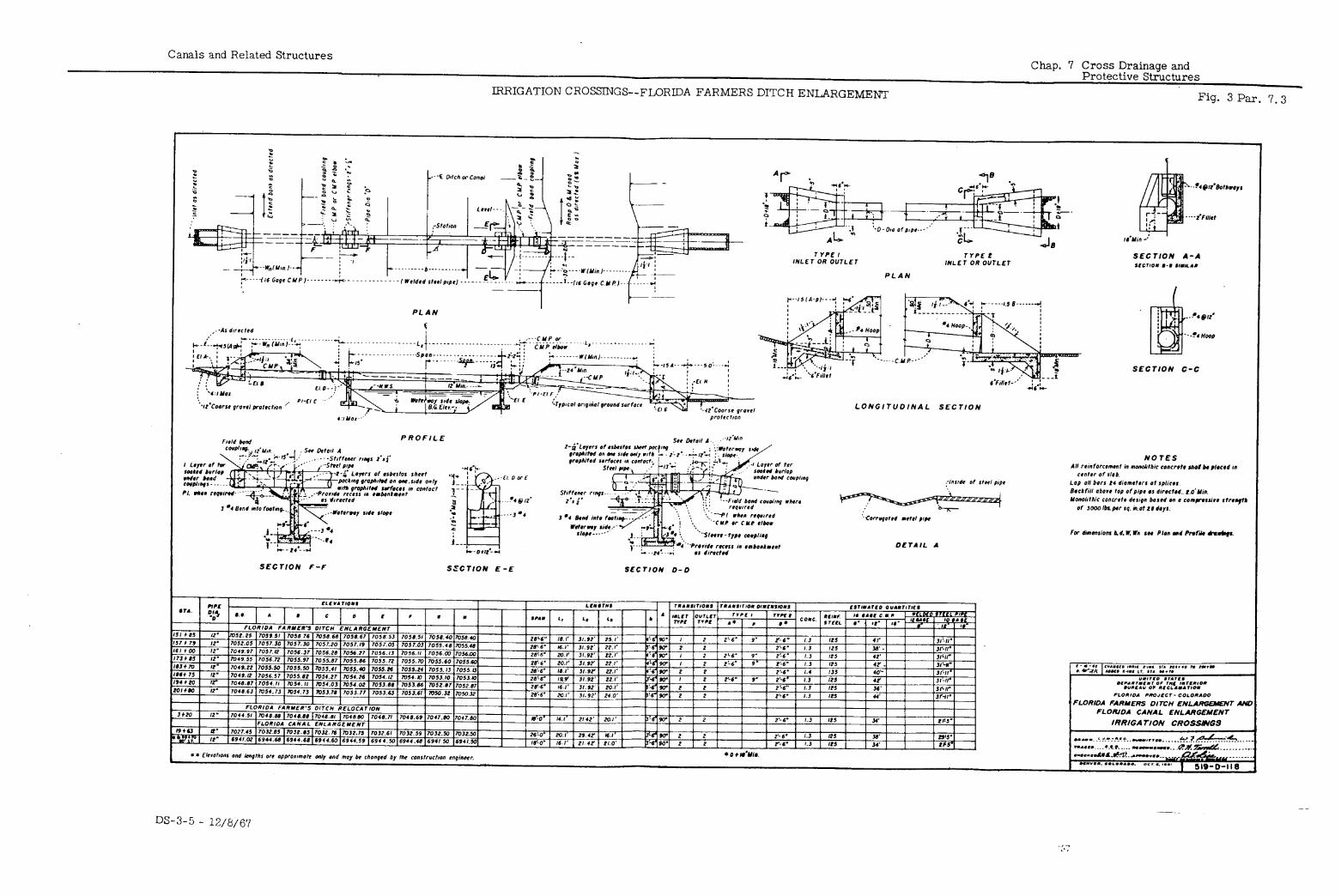
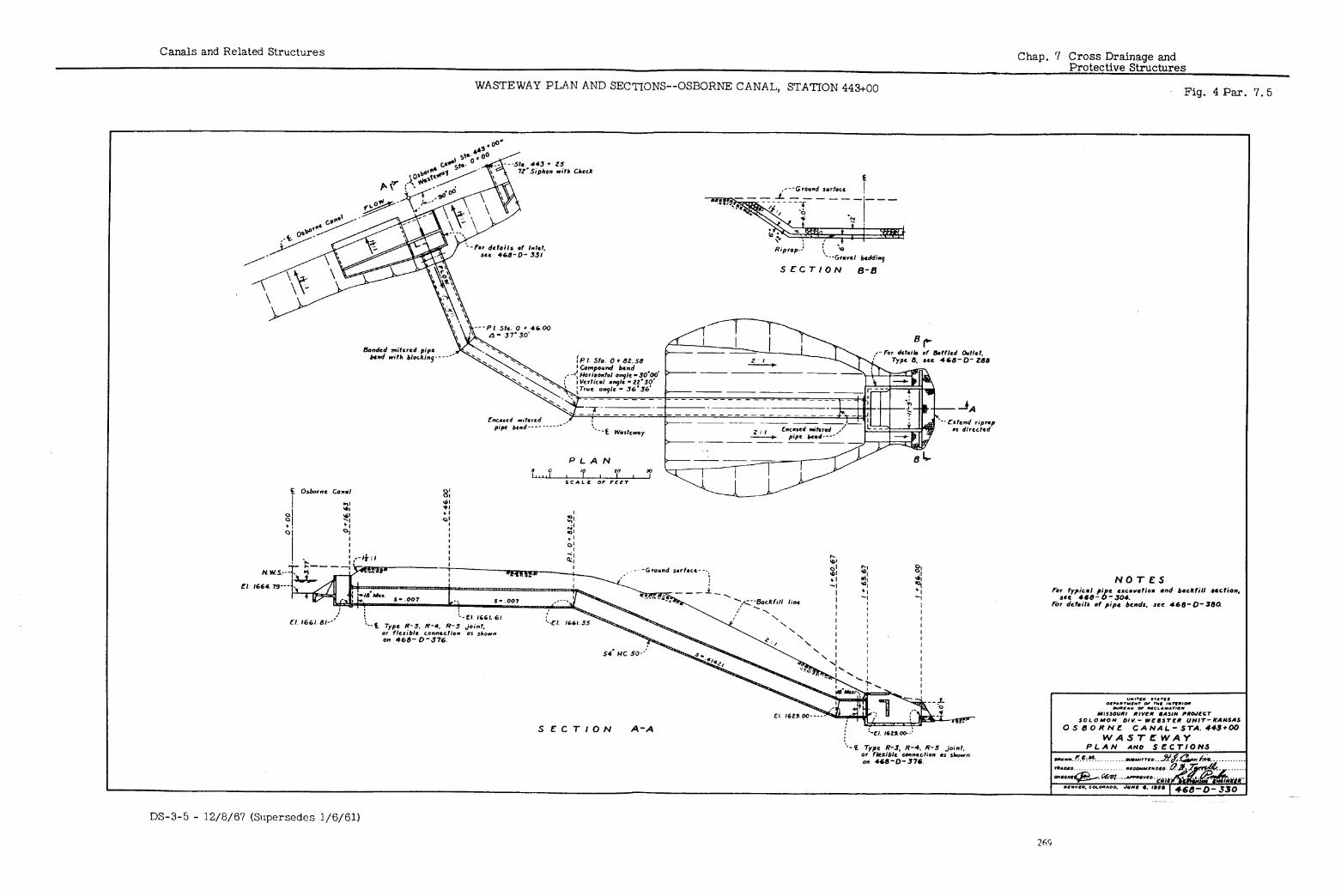
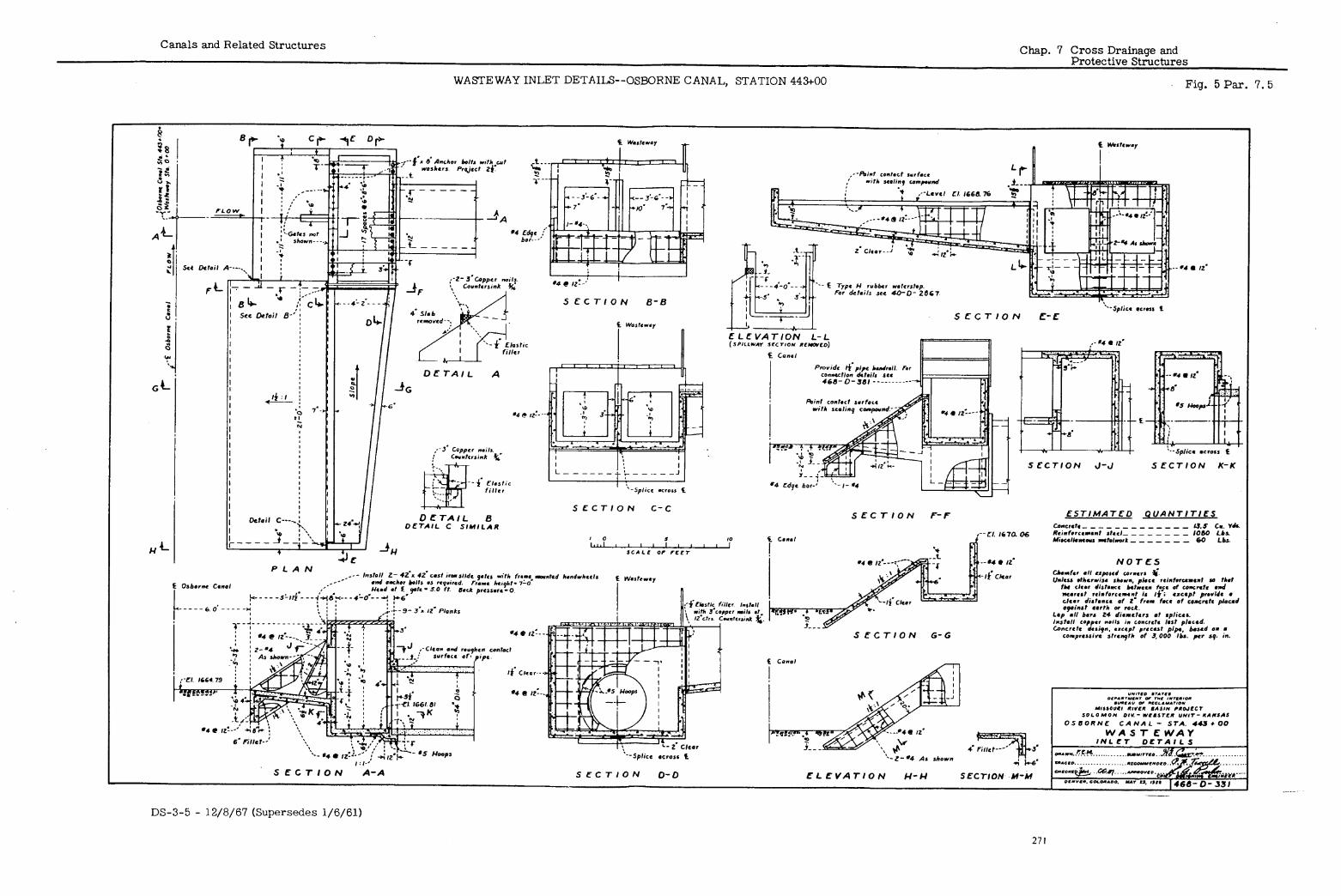
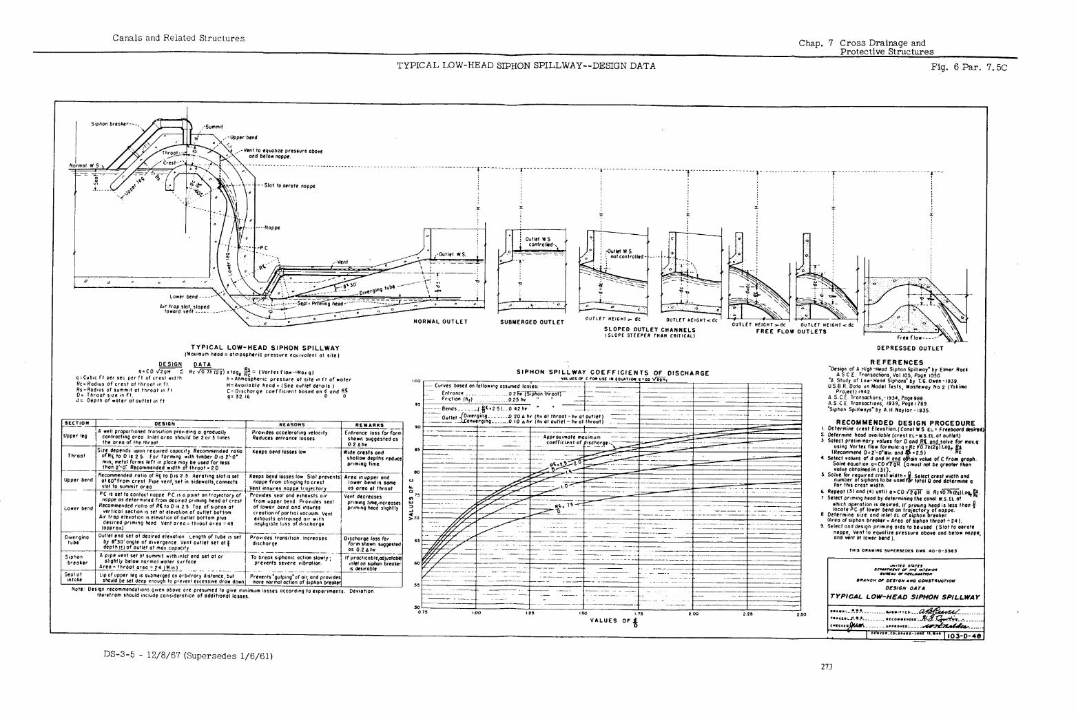
Canals and Related Structures Chap. 8 Pipe Distribution Systems
TABLE OF CONTENTS
Paragraph
i::, i-F 8: 3A
EA 8: 4B 8.4C 8.5 8.5A 8.5B 8.5C 8.5D
Introduction Open or Limited Pressure System
Operational Requirements Closed or Full Pressure System
Operational Control in Open Pipe Systems Field Data Required for Design
Headgate Diversion Requirements Farm Delivery Capacities Farm Delivery Heads
Type of Pipe Unreinforced Concrete Irrigation Pipe Concrete Pressure Pipe Other Concrete and Steel Pipe Asbestos-cement Pipe
-
DS-3-5 - 12/8/67
215
Chap. 8 Pipe Distribution Systems Canals and Related Structures
TABLE OF CONTENTS--Continued
LIST OF FIGURES
Figure Number
Paragraph Reference
B Typical Pipe Stands 8.2 Horizontal Line Meter Installations--
Shafter- Wasco Irrigation District--
3
4
Friant-Kern Canal Distribution Systems 8.3 Vertical Flow Meter Stand, Installation
Type T--Unit 1 Extension,. Southern San Joaquin Municipal Utility District-- Friant-Kern Canal Distribution Systems 8.3
Delivery Installations, Types A- 1, A -2, A-3, A-4, and A-5--Westlands Water
5
6
District Distribution System Delivery Installations--Colusa County
8.4
Water District, Unit 1B 8.4 Typical Deliveries From 4-Inch Outlets 8.4
.
Drawing Number
103-D-1065
214-D-19801
214-D-19527
103-D- 1068
103-D-1066 103-D-1067
.-
DS-3-5 - 12/8,‘67 276
Canals and Related Structures Chap. 8 Pipe Distribution Systems
8.1
.1 In pipe distribution systems, buried closed conduits are used for conveyance INTRODUCTION of irrigation water to the delivery point on the farmer’s land. Normally, pipelines are placed adjacent to roads and may be, installed both up and down slope if the pipe can be kept below the hydraulic gradient. There is no neces- sity to contour as in the case of a canal. Hydraulic head sufficient to serve farm deliveries, including friction loss in farm laterals, is carried in the pipeline as pressure head. Each delivery is usually provided with a meter for measuring the rate of flow and for totalizing the amount of water delivered. Design criteria for individual open (or limited pressure) and closed (or full pressure) systems have been developed. pump or gravity service areas.
Either may be adapted to use for
The closed (or full pressure) system may be one of two types. One type gives the farmer only a few feet of head so he can put in a pressure pipe system or an open ditch system to distribute water on his land. The other type assures the farmer sufficient head (78 feet or more) to distribute water on the land by sprinklers.
.2
General structural and hydraulic design criteria relating to pipe distribution systems are given in Chapter 2. In the structural drawings selected for illus- tration, there may be instances in which current design practices differ in some respects from those illustrated.
The open or limited pressure system utilizes low-head pipe with open baffle or gate-controlled stands located at irregular intervals along the pipeline (see Figure 11. Equal spacing of stands may cause serious line surges at partial capacity flow. The baffle serves the same purpose as a check and its top elevation should be set so that static water level will provide suffi- cient head to all farm deliveries between the stand and the next upstream baffle when the reach is operating at zero flow beyond the baffle. The top of the stand should be set to provide minimum freeboard above water surface for maximum design capacity flowing over the baffle as a weir. The weir
.may operate either submerged or free fall; however, the latter condition may result in considerable air entrainment and thus require air vents from the pipeline. All pipe is designed to withstand the head measured from the hy- draulic gradient (for maximum demand) to the centerline of the pipeline, and is sized to provide full water supply to the farm units. To limit pressure on delivery valves, to permit the use of low-head pipe, and to make the stands more accessible and less costly, the baffle height is usually limited to less than 20 feet. This type system should only be used when a closed or full pressure system is not practical.
OPEN OR LIMITED
PRESSURE SYSTEM
A. Operational control for an open pipe system must be from the head of each lateral, branch line, and farm delivery. Care must be exercised,
Operational Control in
in making changes in demand on the system, to prevent overtopping of stands or waste through overflows installed in the stands. Meters and
Open Pipe
throttling valves should be placed at the heads of all laterals, sublater- System
als, and farm deliveries, to enable the operators to perform the neces- sary regulation. Pipe subject to freezing must be drained during the nonoperating season. of each line.
Wasteways are usually required at or near the end
.3 The closed or full pressure system uses medium- to high-head pipe, depend- CLOSED ing on the topography and the farm delivery head required. Normally, closed OR FULL systems operate from the water surface elevation occurring at the intake of PRESSURE the distribution network or from a head created by pumping. All pipe is de- signed to withstand pressures measured from the static head at the intake
SYSTEM
plus adequate allowances for water hammer that results from valve closures. Where topography is steeply sloping, it may be economical to install pressure- reducing valves or a water surface controlled open tank in the main lines to
DS-3-5 - 12/8/67 277
Chap. 8 Pipe Distribution Systems Canals and Related Structures
8.3A
CLOSED OR FULL PRESSURE
SYSTEM (Cont’d. 1
Operational Require-
ments
FIELD DATA
REQUIRED FOR DESIGN
drop the hydraulic gradients. If pressure regulators are used, the downhill system must have some type of protection such as a relief valve to protect the ‘lower system from regulator valve malfunction. An overflow must be provided from the open tank to bypass the flow into a natural watercourse or into the discharge line downstream in the event the tank controls fail to oper- ate properly. pipe.
Failure to provide this protection may result in bursting of the Pipelines are sized to provide for the total governing farm deliveries
during periods of maximum demand.
A. Operational control for a closed system is exercised at the individaul farm delivery, where flow is adjusted by means of a throttling valve. Since the drop in head across this regulating valve may be appreciable when a delivery is operated during periods of minimum system demand, cavitation will result below the valve unless some type of protection is provided. Figures 2 and 3 show installations that have proved success- ful for differential heads up to 100 feet across the valve. Valve adjust- ments on farm deliveries should be made slowly so that excessive pressure surges in the lateral pipe system will be avoided. In general, the closed system, is easier to operate and requires fewer operators than the open system. For deliveries or sublaterals in a pipe system provid- ing sprinkler pressures, pressure reducing valves may be installed * where the line pressure at the delivery exceeds 100 pounds per square inch under maximum operating heads.
.4 Field data required for the design of a pipe distribution system are much the same as for an open lateral system. in the following paragraphs.
Other design considerations are given
Headgate Diversion
Requirements
A. System headgate diversion requirements should be computed as for an open canal and lateral system, except that:
(1) Water transmission losses are small and are negligible compared to those in an open canal.
Farm Dalivery
Capacities
(2). In a given area, net acreages to be irrigated by a pipe distribution system will be greater than those for an open lateral system by the portion of the farm ownerships normally deducted for canal and lat- eral rights-of-way.
B. Farm delivery capacity requirement of a pipe system is computed the same as for a canal system because each must furnish the turnout the required amount of water during the period of maximum system demand.
(1) The minimum theoretical pipeline capacity must deliver farm head- gate requirements with continuous 24-hour operation of the turnout throughout the maximum demand period. In order to reduce farm labor costs, it is customary (where the soil infiltration rates permit) to select the farm delivery capacity so as to deliver full requirements to several farmers on a turn or ~~rotation’l basis. Criteria developed on this basis usually employ a “sliding” time requirement scale so that small acreages require less time per irrigation than larger hold- ings. Details of the farm delivery rotation plan should be worked out in cooperation with irrigation district officials or with an irrigation agronomist.
(2) The construction cost increases more rapidly for pipe systems than for open laterals when the capacity increases; therefore, the rotation plan for deliveries is used more extensively than demand irrigation for pipe distribution systems.
.
. -
DS-3-5 - 12/8/67 278
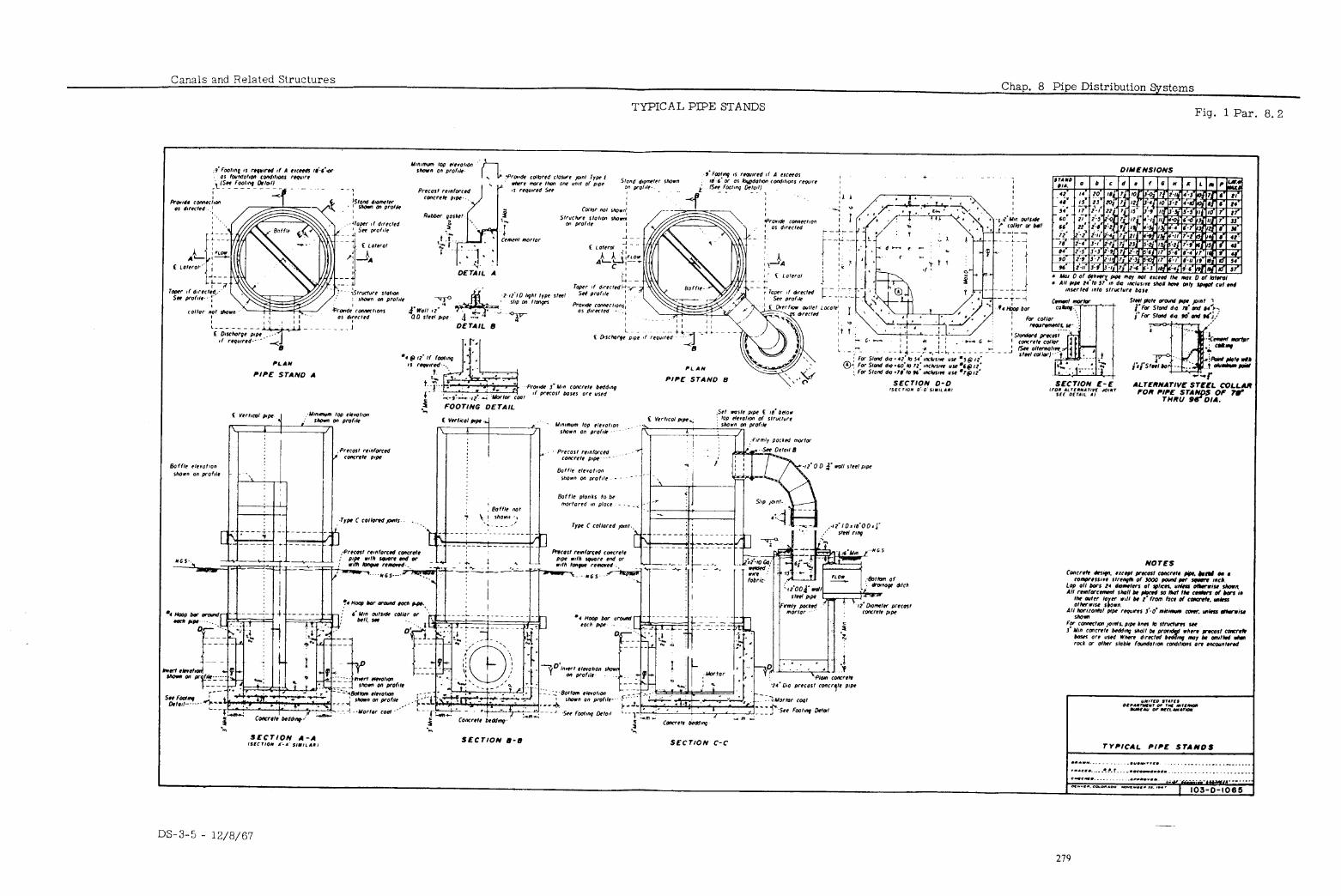
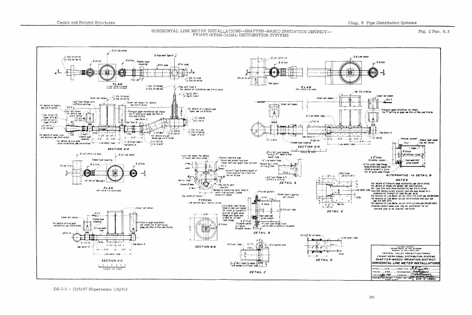
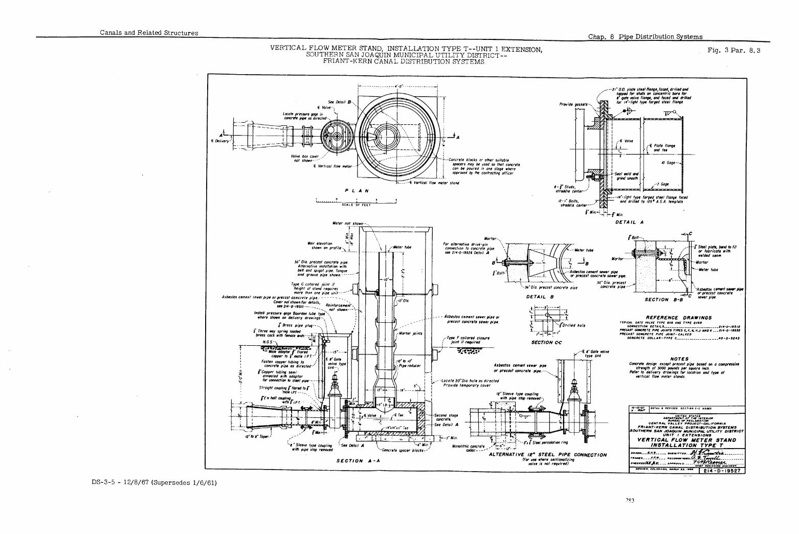
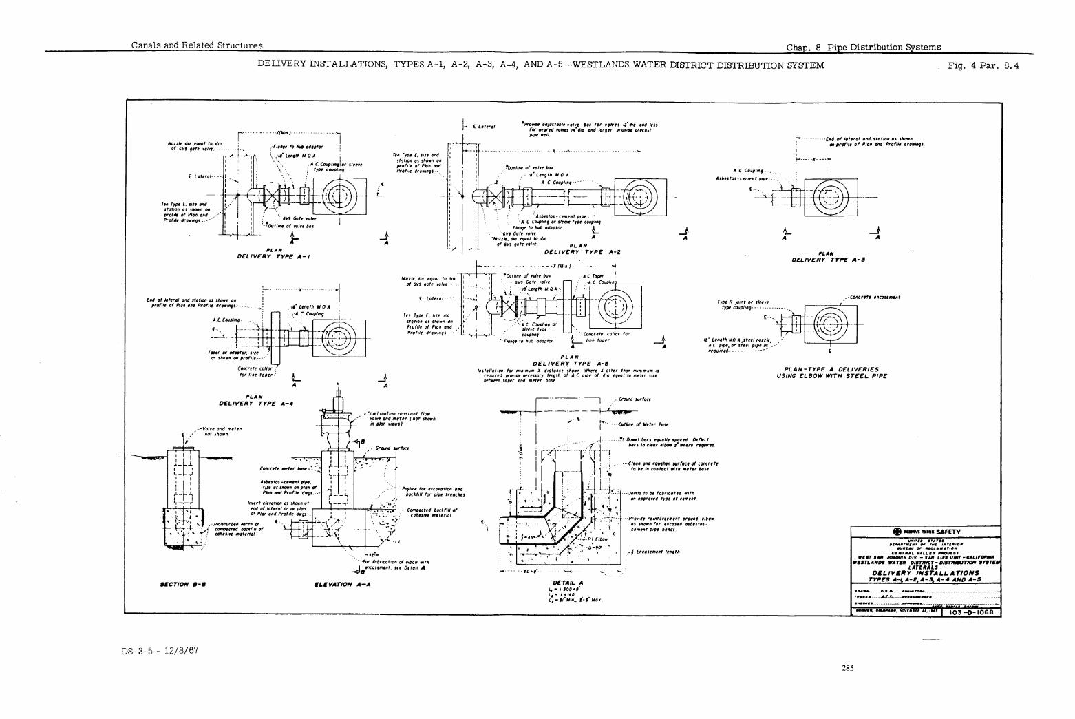
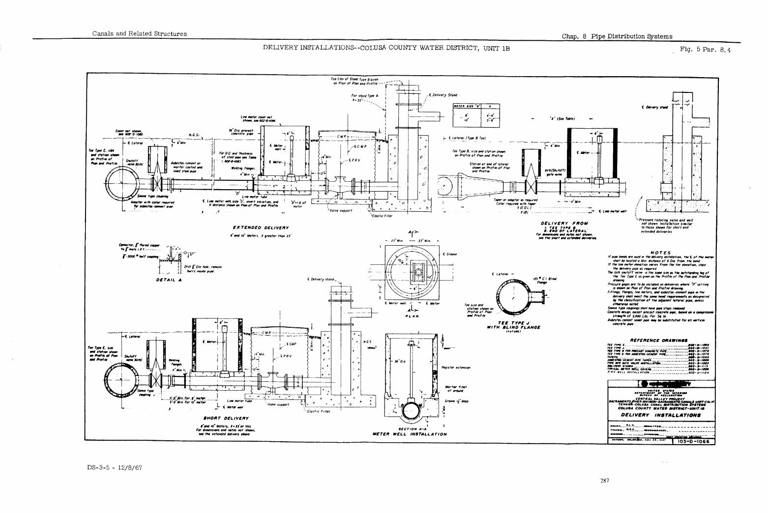
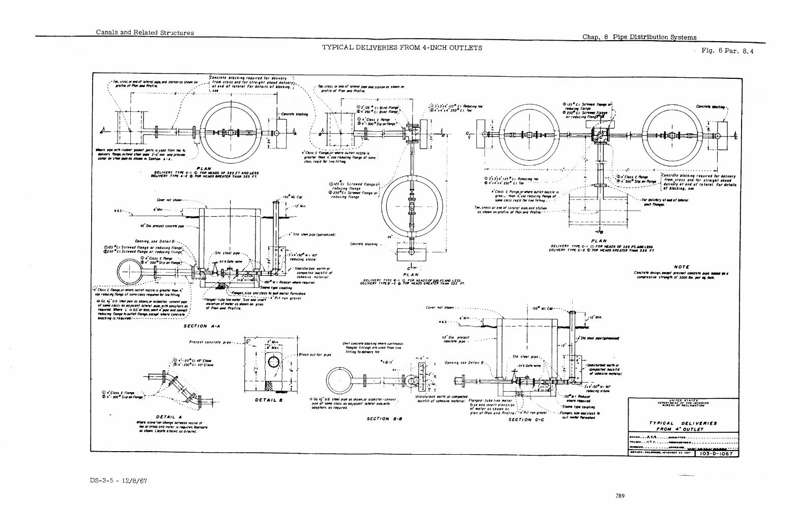
Canals and Related Structures Chap. 8 Pipe Distribution Systems
8.4C
C. Unless modified by an overall plan of operation adopted by the irrigation FiWXLl district, farm delivery heads required for a pipe distribution system should be as follows:
Delivery Heads
(1)
(2)
. (3)
Where a farm unit is served by an open farm ditch, locate the deliv- ery at the high point of the land as for a delivery from a canal system. Provide a minimum net head (after delivery losses have been de- ducted) sufficient to permit effective flow in the farm ditch. Fre- quently, minimum net head is assumed to be from 1 to 2 feet above ground surface at the point of delivery.
Where the farmer’s delivery system is to be pipe with gravity out- lets, the minimum net delivery water surface elevation should be computed to provide not less than 2 feet above highest ground surface elevation in the area served plus an appropriate head allowance to compensate for the friction loss in the farmer’s pipelines. A mini- mum of 5 feet above the adjacent ground surface is frequently provided.
Where the farmers intend to utilize sprinkler irrigation, delivery pressures ranging from 35 to 100 pounds per squsre inch are gen- erally desired. These pressures may be provided at the farm turn- out either by gravity or by a pumping plant in the system. However, when the desired sprinkler pressures are not provided at the farm turnout, the farmers wiJl have to provide them with their own pump- ing plants. Open-pit, wet-well-type pumping plants are recommended. Direct connection of the farmers’ pumping plants to the lateral pipe- lines is not desired as it would require the entire lateral system to be designed for the water-hammer heads imposed.
Figure 4, is an example of a delivery that requires the farmer to install an open structure downstream of the combination constant- flow valve and meter, if he wants to use a booster pump. Figure 5 is an example of a delivery that provides a limited amount of head (height of delivery stand) to the farmer. If the farmer wants addi- tional head, he can add a booster pump downstream of the stand. The pressure-reducing valve (P. R. V. 1 before the stand provides constant head and prevents the water from overflowing the top of the stand. Figure 6 is an example of a delivery that provides full sprinkler pressure to the farmer.
.5 The type of pipe used in distribution systems depends on the head, cover, and local conditions. Tz?F
A.
B.
C.
Unreinforced concrete pipe with rubber-gasket& joints may be used in Unreinforced diameters up to 30 inches for heads up to 20 feet. Concrete
Irrigation Pipe
Except where the low-head unreinforced concrete pipe previously men- Concrete tioned is suitable, reinforced concrete pressure pipe with rubber-gasket Pressure joints is normally used for heads up to 125 feet. Standard designs are available for pipe 12 to 108 inches in diameter with pressure heads from
Pipe
25 to 125 feet. Special designs are usually prepared for concrete pres- sure pipe larger than 108 inches in diameter.
Prestressed pipe, pretensioned pipe, steel pipe, or specially designed concrete cylinder pipe is normally used when heads exceed the maximum
OtherdCs~eete
allowed for concrete pressure pipe. (Note: Prestressed pipe is concrete pipe with spirally wound reinforcement prestressed to produce an initml
Pipe
compressive stress in the concrete; and pretensioned pipe consists of a
DS-3-5 - 12/8/67 291
8.5D
Chap. 8 Pipe Distribution Systems Canals and Related Structures
Other Concrete and Steel
Pipe (Cont’d. )
steel cylinder wrapped with reinforcement to provide an initial compres- sive stress in the cylinder, with a concrete lining and an external con- Crete coating. 1
Asbestos- cement
Pipe
D. Asbestos-cement pipe is used optionally in sizes 36-inch diameter and smaller, and it may be competitive with ordinary reinforced concrete pipe, pretensioned pipe, prestressed pipe, and steel pipe.
.
l
DS-3-5 - 12/8/67 292
Canals and Related Structures
TABLE OF CONTENTS
Chap. 9 Bridges
GENERAL CONSIDERATIONS
Paraqraph
9”:;
E 9:4A 9.4B 9.4c 9.4D 9.4E 9.4F
Ei
.
E 9:9
9.10 9.11 9.1lA 9.11B 9.llC 9.11D 9.11E 9.11F 9.11G 9.11H 9.11-I 9112 9.13 9.13A 9.13B 9.1x 9.13D 9.13E
Specifications Classes of Bridges Alinement and Grades Width of Roadways and Loadings
Temporary Bridges Farm Bridges Operating Bridges County and Highway Bridges Access Bridges Railroad Bridges
General Design Considerations Types of Bridges
TEMPORARY TIMBER BRIDGES
General Material Railings
CONCRETE AND STEEL HIGHWAY BRIDGES
General Selection of Type of Bridge
Simple Concrete Slab Spans Continuous Haunched Concrete Slab Spans Precast Prestressed Slab Spans With Voids Cast-in-place Concrete Beam Spans Rolled Steel Beam Spans Prestressed or Post-tensioned Beams Plate Girder Spans Truss and Arch Spans Rigid Frame Spans
General Selection of Type of Bridge
Rolled Steel Beam Spans Steel Girder Spans Prestressed Concrete Box Girder Spans Truss Spans Reinforced Concrete Trestle Spans
DS-3-5 - 12/8/67
293
Chap. 9 Bridges Canals and Related Structures
TABLE OF CONTENTS--Continued
. ._ , . _ .j.. , . . ..;+
Figure Number
;
3
4
5
6
7
8
9
10
11
12
13
14
15
16
17
18
19
20
LIST OF FIGURES
Heavy Equipment Loading Diagrams Temporary Timber Bridges--Floor,
Stringers, and Bents County Highway Bridge--Slab, Beams,
Abutments, Piers--Delta-Mendota Canal
County Road Bridges--Slab, Abut- ments, Pier--Tehama-Colusa Canal, Reach 2
County Road Bridges--Plan, Eleva- tion, Sections--Tehama-Colusa Canal, Reach 2
County Road Bridges--Plan, Eleva- tion, Sections--Sherman Feeder Canal
Concrete Bridges--Plan, Elevation, Sections--Extension of Welton- Mohawk Main Outlet Drain
Farm Bridge--Tehama-Colusa Canal, Reach 2
State Highway Bridge--Plan, Eleva- tion, Sections--Wahluke Branch Cd
State Highway Bridge--Plan, Eleva- tion, Sections--Feeder Canal, Columbia Basin
Bridge Across Lind Coulee--Plan, Elevation, Sections--O’Sullivan Dam-Moses Lake Connection
Spillway Channel Bridge--Plan, Elevation, Sections--Kirwin Dam, County Road Relocation
Putah Creek Bridge--General Plan and Elevation--Relocation State Highway No. 28, California
Derrick Avenue Bridge--Plan, Elevation, Sections--San Luis Canal
Fresno-Coalinga Read Bridge--Plan, Elevation, Sections--San Luis Canal
Trashrack Structure Access Bridge-- Plan, Elevation, Sections--San Luis Dam
Solomon River Bridge--Plan, Eleva- tion, Sections--Mitchell County Highway C -705 Relocation, Kansas
Trinity River Bridge--Plan, Eleva- tion, Sections--Trinity County Road Relocation Carrville to Cedar Creek
Spillway Bridge--Plan, Elevation, Slab, Railing--Cedar Bluff Dam
Intake Structure Access Bridge-- Plan, Elevation, Sections-- Sanford Dam, River Outlet Works
Paragraph Reference
.Q. 4C
9.7
Drawing Number
103-D-230
103-D-23
9.11 214-D-15334
9.1I.A 602-D-960
9. 11A 602-D-959
9. 11B 707-D- 195
9. 11C 998-D-35
9. 11C 602-D-977
9. :lD 222-D-21764
9. 11D 222-D-13713
9. 11E 222-D-14366
9. 11E 37 l-D-237
Q.llF
9. 11F
Q.llF
413-D-30
805-D-2449
805-D-2744
9. 11G 805-D-250
9.116 495-D-347
9.21G 416-D-484
9. 11H 372-D-186
9. 11H 662-D-40
DS-3-5 - 12/8/67 y i . ..-J
294
Canals and Related Structures
TABLE OF CONTENTS--Continued
Chap. 9 Bridges
LIST OF FIGURES--Continued
Figure Number
21
22
23
24
25
26
27
28
29
30
31
Glen Canyon Bridge--General Plan and Elevation--Glen Canyon Dam
Waterholes Canyon Bridge--General Plan and EleGation--Glen Canyon Dam Access Highway
Northern Pacific Railroad Bridge-- Plan, Elevation, Sections--East Low Canal
C. M. St. P. and P. Railroad Bridge-- Plan, Elevation, Deck--East Low Canal
Northern Pacific Railroad Bridge-- Plan, Elevation, Sections--East Low Canal, Rocky Coulee Wasteway
Union Pacific Railroad Relocation, Red Rock River Bridge--Plan, Ele- vation, Abutments--East Bench Unit
Union Pacific Railroad Relocation, Red Rock River Bridge--Steel Plan, Girders, Deck--East Benqh Unit
Relocation C. B. &Q. Railroad, Bridge Mile 318.41--Plan, Elevation, Sec- tions--Boysen Unit
Relocation C. R. I. &P. Railroad, Bridge 3274--Plan, Elevation, Sections--Norton Dam
Relocation C. B. &Q. Railroad, Bridge Mile 318.28--Plan, Eleva- tion, Sections--Boysen Unit
Southern Pacific Railroad Crossings for Canal and Equalizing Floodway, San Luis Canal--Prestressed Box Girders
Paragraph Reference
Drawing Number
9.11H 557-D-43
9.11-I 557-D-25
9.13A 222-D-16611
9.13A 222-D-16614
9.13B 222-D-13947
9.13B 699-D-6
9.13B 699-D-7
9.13B 285-D-152
9.13B 492-D-8
9.13B
\
9.13c
285-D-141
805-D-3514
DS-3-5 - 12/8/67 295
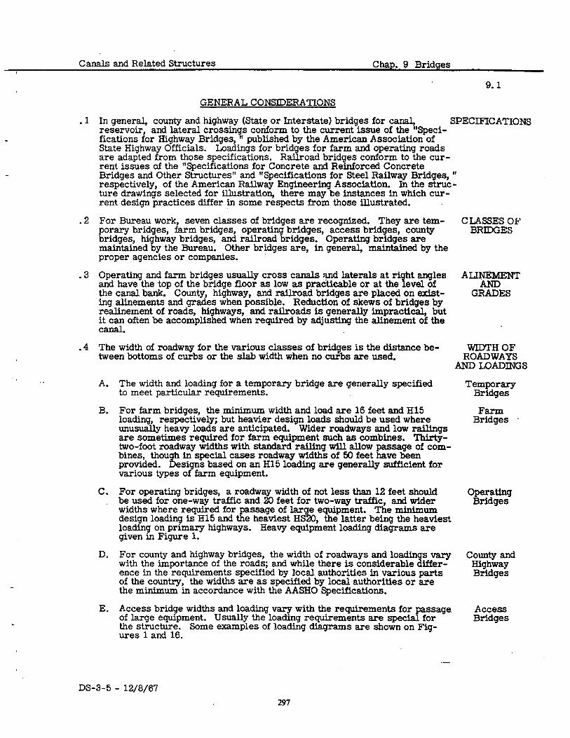
Canals and Related Structures Chap. 9 Bridges
.1
.2
.3
.4
9.1
GENERAL CONSIDERATIONS
In general, county and highway <State or Interstate) bridges for canal, SPECIFICATIONS reservoir, and lateral crossings conform to the current issue of the “Speci- fications for Highway Bridges, ” published by the American Association of State Highway Officials. Loadings for bridges for farm and operating roads are adapted from those specifications. Railroad bridges conform to the cur- rent issues of the “Specifications for Concrete and Reinforced Concrete Bridges and Other Structures” and “Specifications for Steel Railway Bridges, ” respectively, of the American Railway Engineering Association. In the struc- ture drawings selected for illustration, there may be instances in which cur- rent design practices differ in some respects from those illustrated.
For Bureau work, seven classes of bridges are recognized. They are tem- porary bridges, farm bridges, operating bridges, access bridges, county
cyRs~i3g
bridges, highway bridges, and railroad bridges. Operating bridges are maintained by the Bureau. Other bridges are, in general, maintained by the proper agencies or companies.
Operating and farm bridges usually cross canals and laterals at ri and have the top of the bridge floor as low as practicable or at the 8
ht angles eve1 of ALTtR!FNT
the canal bank. County, highway, and railroad bridges are placed on exist- GRADES ing alinements and grades when possible. Reduction of skews of bridges by realinement of roads, highways, and railroads is generally impractical, but it can often be accomplished when required by adjusting the alinement of the Cd.
The width of roadway for the various classes of bridges is the distance be- WIDTH OF tween bottoms of curbs or the slab width when no cuibs are used. ROADWAYS
AND LOADINGS
A. The width and loading for a temporary bridge are generally specified to meet particular requirements.
B. For farm bridges, the minimum width and load are 16 feet and H15 loading, respectively; but heavier design loads should be used where unusually heavy loads are anticipated. Wider roadways and low railings are sometimes required for farm equipment such as combines. Thirty- two-foot roadway widths with standard railing will allow passage of com- bines, though in special cases roadway widths of 50 feet have been provided. Designs based on an H15 loading are generally sufficient for various types of farm equipment.
C. For operating bridges, a roadway width of not less than 12 feet should be used for one-way traffic and 20 feet for two-way traffic, and wider widths where required for passage of large equipment. The minimum design loading is H15 and the heaviest HS20, the latter being the heaviest loading on primary highways. given in Figure 1.
Heavy equipment loading diagrams are
D. For county and highway bridges, the width of roadways and loadings vary with the importance of the roads; and while there is considerable differ- ence in the requirements specified by local authorities in various parts of the country, the widths are as specified by local authorities or are the minimum in accordance with the AASHO Specifications,
E. Access bridge widths and loading vary with the requirements for passage of large equipment. Usually the loading requirements are special for the structure. ures 1 and 16.
Some examples of loading diagrams are shown on Fig-
Temporary Bridges
Farm Bridges
Operating Bridges
County and Highway Bridges
Access Bridges
DS-3-5 - 12/8/67 297
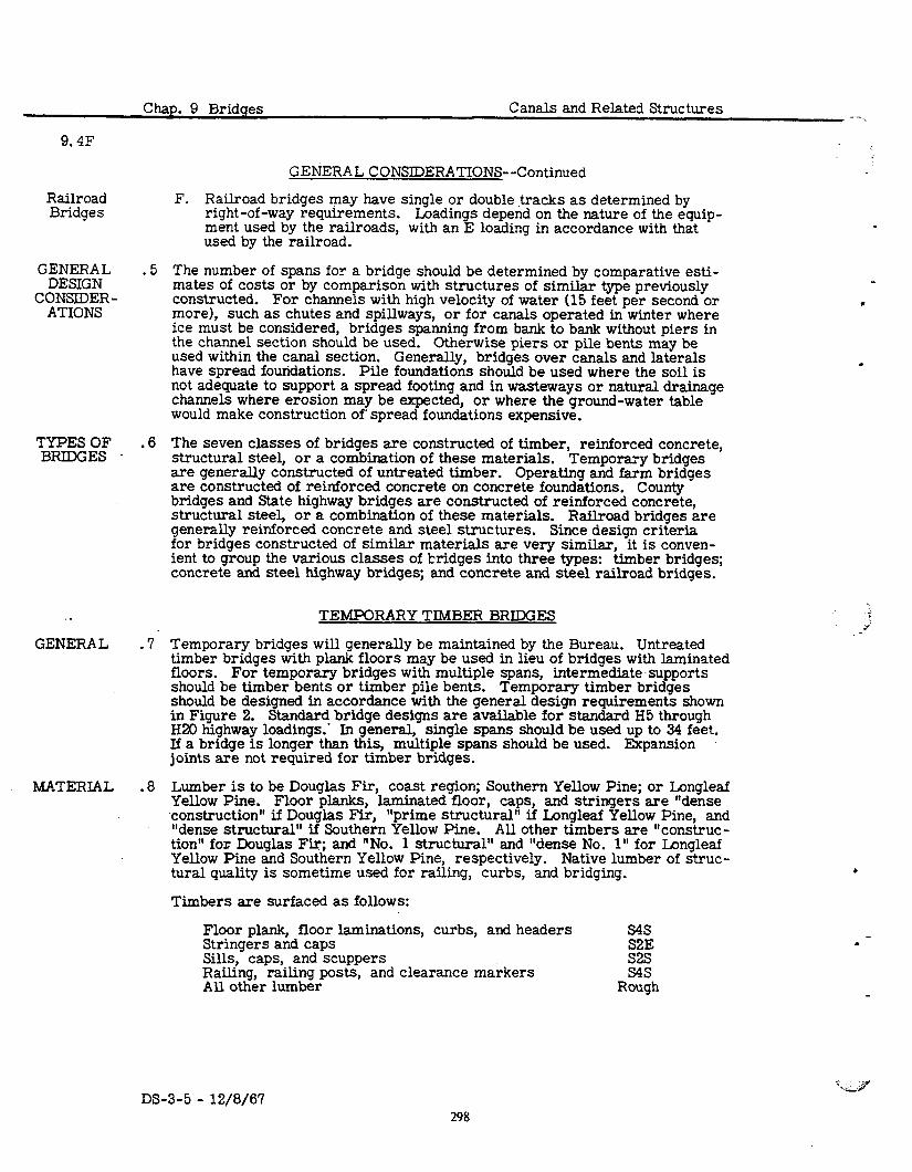
9.4F
Chap. 9 Bridges Canals and Related Structures
GENERAL CONSIDERATIONS--Continued
Railroad Bridges
F. Railroad bridges may have single or double tracks as determined by right-of-way requirements. Loadings depend on the nature of the equip- ment used by the railroads, with an E loading in accordance with that - used by the railroad.
GENERAL .5 DESIGN
The number of spans for a bridge should be determined by comparative esti-
CONSIDER- mates of costs or by comparison with structures of similar type previously constructed.
ATIONS For channels with high velocity of water (15 feet per second or
more), such as chutes and spillways, or for canals operated in winter where ice must be considered, bridges spanning from bank to bank without piers in the channel section should be used. used within the canal section.
Otherwise piers or pile bents may be
have spread foundations. Generally, bridges over canals and laterals
Pile foundations should be used where the soil is not adequate to support a spread footing and in wasteways or natural drainage channels where erosion may be expected, or where the ground-water table would make construction of’ spread foundations expensive.
TYPES OF . BRIDGES .
,6 The seven classes of bridges are constructed of timber, reinforced concrete, structural steel, or a combination of these materials. are generally constructed of untreated timber.
Temporary bridges Operating and farm bridges
are constructed of reinforced concrete on concrete foundations. County bridges and State highway bridges are constructed of reinforced concrete, structural steel, or a combination of these materials. generally reinforced concrete and steel structures.
Railroad bridges are Since design criteria
GENERAL .
for bridges constructed of similar materials are very similar, it is conven- ient to group the various classes of bridges into three types: timber bridges; concrete and steel highway bridges; and concrete and steel railroad bridges.
TEMPORARY TIMBER BRIDGES
7 Temporary bridges will generally be maintained by the Bureau. Untreated timber bridges with plank floors may be used in lieu of bridges with laminated floors. For temporary bridges with multiple spans, intermediate’supports should be timber bents or timber pile bents. Temporary timber bridges should be designed in accordance with the general design requirements shown in Figure 2. Standard bridge designs are available for standard H5 through H20 highway loadings.’ In general, single spans should be used up to 34 feet. If a bridge is longer than this, multiple spans should be used. Expansion joints are not required for timber bridges.
MATERIAL .8 Lumber is to be Douglas Fir, coast region; Southern Yellow Pine; or Longleaf Yellow Pine. Floor planks, laminated floor, caps, and stringers are “dense construction” if Douglas Fir, “prime structural” if Longleaf Yellow Pine, and “dense structural” if Southern Yellow Pine. All other timbers are “construc- tion” for Douglas Fir; and “No. 1 structural” and “dense No. 1 I’ for Longleaf Yellow Pine and Southern Yellow Pine, respectively. Native lumber of struc- tural quality is sometime used for railing, curbs, and bridging.
Timbers are surfaced as follows:
Floor plank, floor laminations, curbs, and headers S4S Stringers and caps S2E Sills, caps, and scuppers s2s Railing, railing posts, and clearance markers S4S All other lumber Rough
.
DS-3-5 - 12/8/67 298
_,-- . Canals and Related Structures Chap. 9 Bridges
9.9
TEMPORARY TIMBER BRIDGES--Continued
Even where untreated timber is used in temporary bridges, bulkheads, cleats, and sills in contact with earth may be treated for longer life if warranted. In
MA~~RRdvfL t . regions infested by termites, contact surfaces and ends of all untreated lum- ber should be coated with wood preservative.
.9 Metal railings 2 feet 8 inches high are to be provided on the temporary timber RAILINGS bridges with surfaced laminated floors. Bridges with plank floor and un- treated timber usually have timber railings 3 feet 6 inches high, but may have a low timber railing.
CONCRETE AND STEEL HIGHWAY BRIDGES
. 10 Concrete and steel highway bridges must meet requirements of the agency for GENERAL which the bridge was designed. These requirements vary considerably for different agencies such as State Highway and County Highway Departments, but in general follow the AASHO Standard Specifications for Highway Bridges. Owing to the variations it has not been practicable to establish standard designs.
. 11 Experience has shown that certain types of bridges tend to be most suitable SELECTION or economical for certain span lengths, but the engineer may prepare eco- OF TYPE nomic studies, including the erection requirements, in the final selection of OF BRIDGE the type to be constructed. In general, for bridges of more than two spans, continuous-type construction offers the most economy, through development of negative moment stresses and permitting fewer required bearings and ex- pansion joints--a desirable feature from the standpoint of maintenance.
It is essential for the safety of continuous-span bridges that they be founded on good foundation material such that the abutments and piers will be free of settlement. However, it is not essential that rock foundation be available, as
.spread footings with low bearing pressures may also be satisfactory. Gen- erally, clay foundations that are dry in the original state and will become wet after a canal is built are not acceptable for continuous structures.
Continuous-type multiple-span bridges may be built without expansion joints by expanding against the earth as shown in Figure 3. If overall length requires expansion joints for movement, fixed bearings and expansion bearings with metal expansion joints in roadway slabs at points of movement are provided. Multiple-span bridges may also be a series of simple spans with sponge- rubber filler joints between spans.
In general, the types of bridge construction are as follows:
A. i;nczte slab spans are generally constructed as simple sl?ans of about Simple maximum length with a maxunum skew of the crossing not ex- Concrete
ceeding 15”. Expansion joints are not required for a one- or two-span Slab Spans . crossing. For the two-span bridge, the positive steel extends through the j&t with spon e-rubber filler material extending into the slab.
b See detail
A, Figure 4. ans are cambered by adjusting forms for dead load deflec- tions. A typical two-span slab bridge is shown in Figure 5.
B. Haunched concrete slab spans are constructed for bridges of three or Continuous more continuous spans only where the foundation will be free of settle- Haunched ment. Maximum span length for this type of structure is approximately Concrete 60 feet. Maximum skew of the crossing should not exceed 15”. A typi- Slab Spans cal three-span haunched concrete slab bridge is shown in Figure 6.
DS-3-5 - 12/8/67 299
9. llc!
Precast Prestressed Slab spans With Voids
cast-in- place
Concrete Beam spans
Rolled Steel
Beam Spans
l?cestressed or Post-
tensioned Bdhms
Plate Yirder spans
Truss and Arch Spans
Chap. 9 Bridges Canals and Related Structures
CONCRETE AND STEEL HIGHWAY BRIDGES--Continued
C. Precast prestressed slabs with voids are used only for simple span con- struction. Lengths of precast units are limited by handling weight, re- sulting in maximum spans of approximately 50 feet. Bridges may be single or multiple span, with sponge-rubber filler provided at piers as illustrated in Figures 7 and 8.
D. Cast-in-place monolithic concrete beam and roadway slab spans are used as sin le-
4 or multiple-span bridges with span lengths of approximately
40 to 0 feet. Figure 9 illustrates the use of two single spans in a bridge with elastomeric bearing pads and sponge-rubber joint between the spans. For economy, two-span bridges are designed as simple spans, while three or more spans may be designed as continuous if foundation mate- rial permits. The degree of skew of the crossing is not limited in this type of construction. Continuous structures may or may not provide for expansion as illustrated by Figures 3 and 10.
E. Rolled steel beam spans with concrete roadway slabs are used for simple or continuous multispan bridges. Economical designs may be obtained by c-e of welded cover plates to beams and using composite design. ure 11 illustrates a steel beam composite design structure.
Fig- On mnlti-
span bridges expansion is provided at one or more locations, depending on the length of the structure, by rocker or roller bearings and metal roadway expansion joints. If camber exceeds the tolerances provided in the specifications, the beams are cambered an amount equal to the cdl- culated deflection due to the total dead load. beam bridge is illustrated in Figure 12.
A typical multispan steel
F. Prestressed concrete beams with concrete roadway slabs are used for spans from 30, to 100 feet. Four standard types of beams are provided by the Joint Committee AASHO on Bridges and Structures end the Pre- stressed Concrete Institute. These beams are generally only used for simple span construction, and in multispan bridges sponge-rubber filler is provided between spans. Elastomeric pads or sliding plate expansion joints are used on shorter spans while ,rocker or roller bearings are used on the longer spans. Provisions must be made for the beam camber re- sulting from prestressing. Examples of these types of structures are shown in Figures 13, 14, and 15.
G. In general, where spans exceed 60 to 80 feet, welded plate girders are econom i.cal. Use of composite design results in additional economy and less depth of structure. The maximum span lengths of girders built are in excess of 400 feet, which allows the engineer a great many selections in strucixe types. The choice of simple, cantilever, or crmtinuons design should be determined by comparative estimates, as no general rule for the determination of the most economical type has been found. The substructure conditions may be a deciding factor in choice of snper- structure. Spans should be provided with field splices of members as governed by the limitations of transportation by railway or highway and by erecting conditions. All spans are provided with expansion bearings of rocker or roller type, and the deck slab is provided with metal expan- sion joints at the ends of the continuous structure. All spans are cam- bered for the total calculated dead-load deflection whenever it exceeds the tolerance provided by the specifications. In addition, defIections due to live loads must be within specification tolerances. Examples of plate girder construction are shown in Figures 16, 17, and 18.
H. Spans in excess of 120 feet may economically be constructed using trusses, depending on loading, clearance, and terrain. In highway con- struction intermediate expansion joints in the roadway slab are provided
DS-3-5 - 12/8/67 300
-- Canals and Related Structures Chap. 9 Bridges
9. U-I
CONCRETE AND STEEL HIGHWAY BRIDGES--Continued
. in spans over 300 feet. All spans are provided with expansion bearings Truss and and a metal expansion joint in the deck at the expansion end of simple or Arch ans continuous trusses. All spans are cambered for the dead load of the sp (Cant d, ) structure. Trusses can be simple, cantilever, or continuous. Other types of structures may be considered such as a tied arch or a two- hinged arch, with the most economical design based on comparative estimates. ures 19, 20,
Examples of truss and arch construction are shown in Fig- and 21.
I. Where studies indicate that it is economical, rigid frame construction may be used. An example is the concrete bridge shown in Figure 22.
Rigid Frame span,s
CONCRETE AND STEEL RAILROAD BRIDGES
. 12 Open timber decks have often been used for railroad bridges, as they are GENERAL generally economical in first cost. However, such decks require special deck framing and do not permit the use of in-line modern mechanized track-
. laying operations as do ballasted decks. Ballasted decks are also less expen- sive to maintain. Therefore, modern railroad requirements, particularly on main lines, may require that ballasted decks be‘used. Closed timber deck or ballasted deck is necessary on overpasses for safety reasons. Ballasted track may be supported on eit.dr concrete or treated timber decks. The con- crete deck may be either constructed of precast concrete units which are readily placed by railway cranes or cast in place. Owing to the large dead load of ballast and timber or concrete decks, bridges of such construction are generally more expensive than bridges with open decks. With railroad approval the use of composite design for some railroad girder bridges, to utilize fully the cast-in-place deck, has produced an economical ballasted deck girder design. As piers for railroad bridges are massive, their number should be held to a minimum for multiple-span bridges on canal crossings, particularly when loss of head in the canal is important. However, crossing a large canal with a single span is usually prohibitive in cost.
. 13 For economy of construction, the type of bridge varies with the length of SELECTION span. The enqineer may prepare economic studies. includinu the erection OF TYPE OF requirements,- in the fir&i seiection of the type of structure 6 be constructed.
A. Steel beams are used for open or ballasted deck with spans up to approx- imately 50 feet. Composite design with cast-in-place deck would allow longer spans and more economy, but would require specific railroad approval. Two steel beams connected by steel diaphragms are generally required under each rail. Simple-span bridges are used rather than con- tinuous spans, for with the heavy live load inherent in all railway con- struction, the uplift forces would require use of expensive anchor bearings on continuous spans. Expansion bearings of sliding plate type are used at the expansion end of simple spans. Figures 23 and 24.
Bridges of this type are shown in
B. Steel girders are generally used for open or ballasted deck bridges of spans 45 to 120 feet. Center-to-center girder spacing for deck bridges varies from 6 feet 6 inches for short spans to 8 feet for the longer spans. For through plate girder spans the spacing of girders. is determined by clearance specifications. Through plate girders should be avoided if possible for economical reasons, except when vertical waterway clear- ances do not permit other types of structure. Through plate girder bridges are illustrated in Figures 25, 26, and 27. Girder spans are pro- vided with rocker- or roller-type expansion bearings. Ballasted deck
BRIDGE
Rolled steel Beam spans
Steel Girder
-
DS-3-5 - 12/8/67 301
Chap. 9 Bridges Canals and Related Structures
9.1x
CONCRETE AND STEEL RAILROAD BRIDGES--Continued
Steei Girder Spans
(Cont’d. 1
Prestressed Concrete
Box Girder Spans
Truss Spans
Reinforced Concrete Trestle
Spans
.-
C.
D.
E.
bridges provide expansion devices to retain ballast. Girders for railway bridges are usually shop fabricated in one piece and usually can be erected by heavy railroad cranes without the need of falsework. Plate girders more than 90 feet in length are cambered equal to the calculated deflec- tion produced by the dead load only. illustrated in Figures 28, 29, and 30.
Deck-type steel girder bridges are
Prestressed concrete box girders are used for ballasted track bridges. These units are erected requiring no falsework, thus reducing the time the railroad is out of operation. The spans are provided with elastomeric pads for expansion and rotation due to deflection. Dowels of sufficient size are provided at. fixed end to transfer the longitudinal loading. The maximum span length of ihis type of span is determined by the capacity of the equipment erecting the box girder. A prestressed concrete box girder of this type is z:iqwn in Figure 31.
Bridges for spans above 120 feet are seldom used for canal crossings, but are used for river crossings in connection with railway relocations and to accommodate reservoir construction. Truss spans exceeding 300 feet require special provisions for expansion in the floor system. Truss design requires special consideration of local conditions dictating their use. All trusses are cambered as required by specifications. An example of a truss railway bridge is shown in Figure 30.
Reinforced concrete trestle bridges are usually composed of a series of ballasted short spans of precast concrete slabs approximately 22 feet &I maximum length, supported on pile bents. The bents usually consist of three or more piles with a cast-in-place reinforced concrete cap. The piles may be either precast reinforced concrete, concrete-filled tubular steel, or steel H piles. Expansion is provided by open joints with as- phalt planks to prevent ballast from entering the opening. The slabs are placed on premolded joint material. Reinforced concrete trestle spans are also used for approach spans for a larger bridge. An example using the reinforced concrete trestle is shown in Figure 28.
l
DS-3-5 - 12/8/67 302
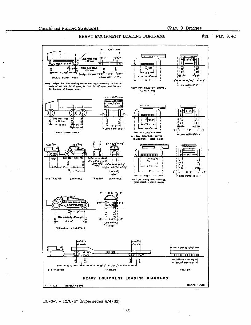
Canald and Related Structures Chap. 9 Bridges
HEAVY EQUIPMENT LOADING DIAGRAMS Fig. 1 Par. 9.4C
YICK DUYP TRUCK
. . _ . .--25.-g . . _. _.
TURNAPULL - CARRYALL
Cl- TON TRACTOR SNOVEL (BucYnus - ERIE 44B)
4 . - - - . . . ,$- I . . ._ .
71 - TOM TRACTOR S”OVEL (BUCYRUS - ERIE 54 B)
HEAVY EOUIPMENT LOADING DIAGRAMS
8.I..., ‘,.,. Iol”S”‘V .-~.,,I, 103-O-230
DS-3-5 - 12/8/6’7 (Supersedes 4/4/62)
303
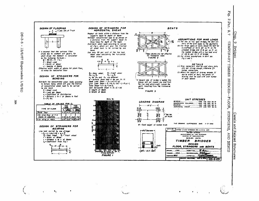
OESIGN OF FLOORINQ
It is assumed thot the extreme liber stress due to moawlt rrll qarern, for rhich stress the momCnt iS COICulOted by thr fotlowinp formula -
M= WdlZ,-FI fll P = Wheel Load f = Width of Wheel s 2 Spocinq of Beams
Effectirc width: width of planks for plonk floor, 15 inches for lominottd floor
DESIGN OgFE;;,$tGERS FOR
Distribvte the conccntrohd wheel toads occordiny to formula be/or, which will pivc the fraction of concentrated wheel load to bc carried by one berm
P -- WAC@1 Load R : Load per Ecom c, = Cocfficlmt of Distribution s 2 Distance c. to c. of Beomr in Feht A =P1 YG
DESIGN OF STRINGERS FOR BEARINQ
Lie load corritd by onr rtrinpu = P, I II- f/&l +s I CI I !
P” = RIO, rhd P, = Front whorl F = Width of Wheel s * Oistohce c. to c. of Beams q * Coefficient from Fi9. I
..I,‘.. I+ “b”.* ,
“rr, . . ..I
-........ l......... L -)r, -
OESIGN OF STRINGERS FOR HORIZON TAl. SHEAR
Ncplcct 011 loads #ithin 0 drstonct from the supports epuol to depth of btom
tteaviut contentroted road to be placed 01 o d,stoncr from the sup~or t cquot .to three times the depth of the blom
Distribute wheel hods occordmp to Curves of Fi9 I, which *iii pivc the froctron ot vhe?I looa to be :orrira by one berm
USI only 90 per cut @t the live load shwr *hen tolrulOtic9 thr horlrontol shcor stress
s = &or wheel, I3 : Front wheel P,, : c* pa fL 2 c, 4 C, for Pa, and PI, ore dtfferent w = Uniform deod load in Ibs. per tin It 0804 Load Shtor - So = NIL/~ -d) Live load S&or = SL=P.,IL-JdI -1 l P.,o- Total sncor = s = so + 0.9 SL Unit Horbontal Sheor = I 8 I S i bd d = Oopth of Btom b * Width of Btom
BENTS
~ytese cobmns arc not rffcctivc for tronsversr 1006s
FIGURE P
ASSUMPTIONS FOR WIN0 LOADS IfI For one or tro span br,d9er, the de0 *ill
wry 011 the rind lords to the abutments 121 For threr spans or mare, destqn the bent ti
o wndhoad of w 18 per sq ft on the unlaoded bridpc, and 15 lb per so ft an the tooded bridqc w;th 0 IIVC load wind Of I00 lb per lin ft Of bridpr
131 For stress assumptions in brnt xc Fig 2 ond 3
k c
‘If teeword ride of bridpr is toodcd, ihis coCmn will not receive ony load from the live load which mi9ht rrducr the rphft reSultin from fh+ tronsvtrst forces
FIOURE s
c
LOADING OIAGRAM \ . . . . . . . ..I ,*.*-.- .._...”
OE TAILS III Rina connectors shall be used where. botts
06 nat strong cnoupn, other.rse fc bolted connectrons
/2/ Where the length of bracmg raetds 32’ due to uvidth of bent, two poncts ot, brocinp shall be used with even number 01 post spoccr
0 l ,