Embed Size (px)
Citation preview

Edition 1 Revision 1
DESIGN STANDARDS
for URBAN INFRASTRUCTURE
13 PEDESTRIAN & CYCLE FACILITIES

ACT Design Standards for Urban Infrastructure
13 PEDESTRIAN & CYCLE FACILITIES
Revision Register Edition / Revision No
Clause No.
Description of Revision Authorised Date
Ed 1 / Rev 0 First Issue
Ed 1 / Rev 1 Various
13.1
13.2
13.3
13.4
13.5
13.6
13.7
13.8
13.9
Section references in text include hyperlink to relevant section. References to NSW Bicycle Guidelines and VicRoads Cyclenotes added.
Added Key Reference Documents Added sections on best practice design, ACT context and policies.
Updated Legislation, Industry standards and Policy and Guidelines including hyperlinks to refereed documents when possible.
Performance statement replaced by objectives.
New section on Main Routes Network.
Planning process expanded and Community engagement added.
Design principles and criteria for pedestrian and cycle facilities added. TCD's, treatment at intersections and roundabouts updated. Section to guide lane width selection for retrofit of on road bicycle facilities added. Coloured pavement treatment - warrant for use added. Tactile Surface Indicators - section added.
Signage section added including guidance on Main routes, destination, behavioural and rural training circuit signage.
Glossary updated.
Standard drawings revised and added to compliment updates addition of sections as above.

Design Standards for Urban Infrastructure
13 Pedestrian & Cycle Facilities Edition 1 Revision 1
13 PEDESTRIAN & CYCLE FACILITIES 13 PEDESTRIAN & CYCLE FACILITIES 1 13.1 Introduction 13-1
13.1.1 General 13-1 13.1.2 Best practice design 13-1 13.1.3 ACT context 13-2 13.1.4 ACT policies 13-2
13.2 Related codes of practice and guidelines 13-3 13.2.1 Legislation 13-3 13.2.2 Industry standards 13-3 13.2.3 Policy and guidelines 13-4
13.3 Objectives 13-4 13.4 Pedestrian and cycle network 13-5
13.4.1 General 13-5 13.4.2 Main Routes Network 13-5 13.4.3 Main Community Routes 13-6 13.4.4 Main On-Road Routes 13-6 13.4.5 Connector Routes 13-6
13.5 Planning of pedestrian and cycling facilities 13-7 13.5.1 Context 13-7 13.5.2 Network planning 13-8 13.5.3 Path facilities in established areas 13-9 13.5.4 On-road cycling 13-9 13.5.5 Community engagement 13-9
13.6 Design of pedestrian and cycle facilities 13-10 13.6.1 Design principles 13-10 13.6.2 Design criteria 13-10 13.6.3 Off-road path types 13-11 13.6.4 On-road cycling 13-12 13.6.5 On-road cycle facilities retrofit on arterial roads 13-16 13.6.6 Coloured pavement treatment 13-19 13.6.7 Geometric design of off-road paths 13-21 13.6.8 Path gradient 13-21 13.6.9 Path cross section 13-22 13.6.10 Pavement design for paths 13-23 13.6.11 Root barriers 13-24 13.6.12 Paths and floodways 13-24 13.6.13 Road crossings 13-24 13.6.14 Use of Tactile Ground Surface Indicators 13-26 13.6.15 Provisions at structures 13-27 13.6.16 Provisions at traffic calming devices 13-28 13.6.17 End of journey facilities 13-28
13.7 Signage 13-28 13.7.1 General 13-28 13.7.2 Main Routes signage 13-28 13.7.3 Main Community Routes signage 13-30 13.7.4 Connector Routes signage 13-33 13.7.5 On-road cycling signage 13-33 13.7.6 Behavioural signage 13-33 13.7.7 Rural training circuit signage 13-34
13.8 Glossary 13-34 13.9 Standard Drawings 13-36

Design Standards for Urban Infrastructure
13 Pedestrian & Cycle Facilities 13-1 Edition 1 Revision 1
13.1 Introduction
13.1.1 General
This Chapter sets out the requirements to be used by Practitioners in the planning and design of pedestrian and cycling facilities in the ACT.
The principal requirements are contained in the following Key Reference documents:
• AUSTROADS Guide to Traffic Engineering Practice, Parts 13 - Pedestrians and 14 - Bicycles, - GTEP13 and 14.
• Roads and Traffic Authority, NSW - NSW Bicycle Guidelines.
• ACT Government, Guidelines for the Planning and Design of Residential Estates.
• NSW Government - Planning Guidelines for Walking and Cycling.
All relevant design principles contained in the reference documents except where noted in this Chapter are to be integrated in the design and planning of pedestrian and cycling facilities and the associated infrastructure.
This standard is to act as a technical support for the Key Reference documents. It aims not to repeat information already contained in these documents but to act as a supplement including elements of design and requirements that are specific to the ACT.
The Australian Road Rules are enforced in the ACT and Practitioners should not design or allow installation of any facility that requires or encourages road users to contravene an Australian Road Rule.
Any reference to Chapter numbers in this document refers to other parts of the Design Standards for Urban Infrastructure.
13.1.2 Best practice design
The Guidelines for the Planning and Design of Residential Estates provides a performance-based approach to the design of new facilities without detailing planning and design requirements, these are provided mainly through GTEP 13 and 14. However, because these documents were developed for application in all Australian jurisdictions some elements detailing the design of facilities were generalised so as not to compromise particular requirements of some jurisdictions. This applies mainly to GTEP 14 and consequently most Road Authorities in other jurisdictions have produced guidelines and notes that supplement GTEP 14.
Given that the ACT is a small jurisdiction and an island within NSW, the NSW Bicycle Guidelines have been adopted for use in the ACT to provide supplementary design guidance to GTEP 14. Supplementary planning guidance should be from the NSW Government - Planning Guidelines for Walking and Cycling where applicable. The use of NSW guidelines to supplement the other accepted guidelines is to encourage a more standardised approach to the planning and design of bicycle and pedestrian facilities through more detailed guidance and examples of acceptable planning and design solutions.
Reference to guidelines and notes from other jurisdictions to aid in a better understanding of the design of safe and innovative solutions is also encouraged.

Design Standards for Urban Infrastructure
13 Pedestrian & Cycle Facilities 13-2 Edition 1 Revision 1
Local bicycle and pedestrian user groups can be a valuable source of information to aid the Practitioner in the planning and design of bicycle and pedestrian facilities. To aid in the promotion of best practice design, the Road Authority generally requires that the Practitioner engage with user groups as part of the design and planning process in the provision of new and gifted cycle infrastructure assets. Refer to Section 13.5.5 for the requirements regarding consultation with user groups.
13.1.3 ACT context
The ACT varies from NSW in the approach to the provision of bicycle facilities in a number of key areas that require consideration in the use of the NSW Bicycle Guidelines as follows:
• All off-road paths including on-street footpaths are a shared facility for pedestrians and cyclists in the ACT. This differs from NSW, where cyclists over 12 years of age are not permitted to ride on footpaths.
• Canberra is a planned city and has a good network of shared paths. However, for faster moving more experienced cyclists who may require a more direct route free of pedestrians and loss of right of way at road crossings, provision of on-road cycling options may be preferred. Due to topography and through design, Canberra does not have a grid or radial street pattern as in other Australian cities and arterial roads are generally the only roads to provide these direct routes. These roads generally have speed limits up to 80km/h and are designed to a high standard generally with controlled access, clearly defined intersections, good sight distances and a much lower volume of heavy vehicles compared to similar roads in other jurisdictions. This is not consistent with the NSW context and Figure 3.2 of the NSW Bicycle Guidelines does not apply in the ACT.
• Linemarking types used in the ACT are to be in accordance with Chapter 9 Traffic Control Devices.
• Directional signage should be in accordance with this standard. Behavioural and regulatory signage detailed in the NSW Bicycle Guidelines may be utilised.
• Parallel parking space width is set at a minimum of 2.3m with an allowance of 0.5m for car door opening to be outside of the traffic lane, with an allowance made for cyclists. Parallel parking is limited to roads with a speed limit of up to 60km/h.
• Hook turns are permitted in the ACT and installation of a bicycle lane between a right turn lane and a traffic lane would not generally be acceptable.
13.1.4 ACT policies
Cycling and walking are supported by the ACT Government and are recognised as healthy, low cost and environmentally friendly forms of transport. The ACT Government has adopted the National Strategy for Ecologically Sustainable Development and the National Greenhouse Strategy. Both of these strategies support an increase in commuter cycling and walking in favour of private car use. Recreation policies also strongly support walking and cycling as a means of improving community health and fitness, and of helping to reduce greenhouse gas emissions and vehicle-produced noise and air pollution.
The Sustainable Transport Plan for the ACT lists targets and actions to increase walking and cycling as sustainable modes of transport in the ACT. The plan aims to increase the journey to work modal split to 5% for cycling and 6% for walking by 2011. A key action of the plan is to develop a master plan for trunk cycle routes, and develop cycling routes and paths to

Design Standards for Urban Infrastructure
13 Pedestrian & Cycle Facilities 13-3 Edition 1 Revision 1
provide an integrated cycling network, including on-road and off-road cycling opportunities. This has commenced, and a Main Routes Network has been developed and is illustrated in standard drawing DS13-11.
It is ACT Government policy to provide on-road cycling lanes on all new arterial roads and consider retrofit of on-road cycle facilities when undertaking maintenance such as resurfacing works that involves eradication and reinstatement of linemarking on arterial roads. All new road projects including gifted assets are to provide for the needs of cyclists and pedestrians in the design of signposting, linemarking and traffic arrangements with particular regard to the Main Routes Network.
ACT Government policy on walking and cycling is subject to change and the Practitioner should check as to current policy whenever planning or designing a project.
13.2 Related codes of practice and guidelines
13.2.1 Legislation
Road Transport (Safety & Traffic Management) Act 1999
Road Transport (General) Act 1999
Disability Discrimination Act 1991
13.2.2 Industry standards
Guide to Traffic Engineering Practice, Part 10: Local Area Traffic Management, AUSTROADS (GTEP 10).
Guide to Traffic Engineering Practice, Part 13: Pedestrians, AUSTROADS (GTEP13).
Guide to Traffic Engineering Practice, Part 14: Bicycles, AUSTROADS (GTEP 14).
AS 1428 Design for Access and Mobility, Part 1 – General Requirements for Access – Buildings, Standards Australia.
AS 1428 Design for Access and Mobility, Part 4 – Tactile Ground Surface Indicators, Standards Australia.
AS 1657 Fixed Platforms, Walkways, Stairways and Ladders. Design, Construction and Installation, Standards Australia.
AS 1742.1 – 2003 Part 1: General introduction and index of signs, Standards Australia.
AS 1742.2 – 2003 Part 2: Traffic control devices for general use, Standards Australia.
AS 1742.9 Manual of Uniform Traffic Control Devices, Part 9 – Bicycle Facilities, Standards Australia.
AS 1742.10 Manual of Uniform Traffic Control Devices, Part 10 – Pedestrian Control and Protection, Standards Australia.
AS 1742.13 Manual of Uniform Traffic Control Devices, Part 13 – Local Area Traffic Management, Standards Australia.
AS 2890.3 Bicycle Parking Facilities, Standards Australia.

Design Standards for Urban Infrastructure
13 Pedestrian & Cycle Facilities 13-4 Edition 1 Revision 1
13.2.3 Policy and guidelines
Australian Road Rules, National Road Transport Commission. http://www.canberraconnect.act.gov.au/transroadstraffic/roadsafety/roadrules/australianroadrules.html
Guidelines for the Planning and Design of Residential Estates, ACT Planning and Land Authority http://www.actpla.act.gov.au/
ACT Crime Prevention and Urban Design Resource Manual, ACT Planning and Land Authority. http://www.actpla.act.gov.au/publications/crime_prevention/ResManual.pdf
Civic Accessibility Study - Volume 3, Department of Urban Services http://www.parksandplaces.act.gov.au/policiesandpublications/civicaccessstudy
Canberra Bicycle 2000 Strategy, ACT Planning and Land Authority. http://www.actpla.act.gov.au/bikebits/bike_files/bikpla.htm
The Sustainable Transport Plan for the ACT, ACT Planning and Land Authority. http://www.actpla.act.gov.au/transportplan
National Greenhouse Strategy, Australian Greenhouse Office http://www.greenhouse.gov.au/government/ngs/index.html
Australian National Cycling Strategy 2005-2010,Australian Bicycle Council http://www.abc.dotars.gov.au
The Canberra Spatial Plan, ACT Planning and Land Authority http://www.actpla.act.gov.au/plandev/sp-intro/index.htm
NSW Bicycle Guidelines, Roads and Traffic Authority, NSW -. http://www.rta.nsw.gov.au/trafficinformation/downloads/nswbicyclev12_i.pdf
Vicroads Cycle Notes, VicRoads http://www.vicroads.vic.gov.au/
Queensland Cycle Notes, Queensland Transport. http://www.transport.qld.gov.au/qt/LTASinfo.nsf/index/cycling_notes
The Bicycle Parking Handbook, Bicycle Victoria http://www.bv.com.au
13.3 Objectives This standard aims to provide Practitioners with a suite of planning considerations and design measures to ensure a consistent approach is maintained in the provision of pedestrian and cycling facilities.
Criteria that detail the performance requirements for the provision of pedestrian and cycling facilities as part of new developments are contained in the Guidelines for the Design and Planning of Residential Estates.
The off-road paths and on-road facilities are an integral part of the overall community transport network. The off-road paths should provide a network of primarily pedestrian facilities to provide generally low speed and volume routes for cyclists with connections to adjoining streets, open spaces, activity centres and the greater trunk path and Main Routes

Design Standards for Urban Infrastructure
13 Pedestrian & Cycle Facilities 13-5 Edition 1 Revision 1
Network. Cyclists must give way to pedestrians on off-road facilities and on-road facilities are provided for faster moving more experienced cyclists.
Both on and off-road facilities should be planned and designed with careful consideration of the key design principles (refer Section 13.6.1) and provide the level of amenity suitable for all of the anticipated user groups including users with limited mobility and parents with prams. The provision of the facilities should encourage pedestrian activities and cycling for transportation and recreational purposes to be undertaken safely and conveniently. This standard details a hierarchy of facilities particular to ACT conditions with a higher level of amenity to be provided on Main Routes to reflect the potential higher usage and function of these routes.
Through good planning, design and construction practices, a pedestrian and cycling network that is cost effective in terms of both capital expenditure and on-going maintenance costs will be delivered to the ACT community.
13.4 Pedestrian and cycle network
13.4.1 General
The pedestrian and cycle network is made up of on-road and off-road facilities. Details of the requirements for off-road paths that are for use by both pedestrians and cyclists are included at Section 13.6.3. On-road facilities are for use by cyclists only and include bicycle lanes, wide marked shoulders and wide kerbside lanes. Details of on-road cycling facilities are included at Section 13.6.4.
The pedestrian and off-road cycle network in the ACT context includes all paths as cyclists of all ages are permitted to use any path in the ACT. This is consistent with the Australian Road Rules, however unlike NSW, the ACT does not have additional laws that limit the use of footpaths by cyclists.
13.4.2 Main Routes Network
A defined main pedestrian and cycling network has been developed and will be reviewed regularly to promote an efficient system to best serve and encourage pedestrians and cyclists. A hierarchy of facilities to best suit different user groups has been developed through public consultation and is to be implemented over time through retrofit and wherever new facilities are provided. Providing a choice in facilities to cater for the needs of different user groups will also contribute to reaching the Sustainable Transport Plan's transport mode share targets for walking and cycling journeys to work.
The Main Routes Network provides a higher level of amenity and links key destinations such as town centres and major employment areas. Other paths including Minor, Intermediate and Trunk paths (refer Table 13–1) feed in to the Main Routes to form a coherent network.
The Main Routes Network is made up of two mutually independent networks, namely Main Community Routes and Main On-Road Routes. Connector Routes provide for linkage between these main routes and where provision of an off-road path is not possible or cyclist volume requires more alternative main routes. Another type of Connector Route exists where local access streets have been used in lieu of a Trunk path in the Main Community Routes network. These are generally missing links in the network but may be marked as Connector Routes due to the infeasibility of providing a Trunk path in some locations due to verge widths and mature trees.

Design Standards for Urban Infrastructure
13 Pedestrian & Cycle Facilities 13-6 Edition 1 Revision 1
The Main Routes Network has been designed such that the users of Main Community Routes will not be required to use Main On-Road Routes to complete a journey.
13.4.3 Main Community Routes
This network is an off-road network made up of Trunk paths, and is provided for walkers and joggers as well as recreational, school and less confident cyclists. Pedestrians have right of way on these routes and with higher pedestrian volumes these paths may become unsuitable for faster moving cyclists. Maintaining right of way for the path user is an important consideration on these routes to assist in the reduction of journey times.
A higher level of amenity is to be provided on these routes, including:
• Higher standard of signage (refer Section 13.7.1) including destination, location and behavioural signage as appropriate.
• Right of way to be provided at driveways and roadway accesses to leased land wherever safe and practicable refer to standard drawing DS-06 for an example of an acceptable driveway crossing treatment.
• To maximise right of way opportunities, path priority crossings should be considered where appropriate (refer Section 13.6.13)
• Lighting of higher volume routes.
• High priority given to removing any missing links in this network.
13.4.4 Main On-Road Routes
This network is an on-road network for use by more experienced, faster-moving cyclists such as commuters, and touring and training cyclists wanting to get to a destination quickly with a minimum loss of right of way. These routes are generally on arterial roads and are suitable for more experienced cyclists comfortable with riding adjacent to vehicular traffic.
A higher level of amenity is to be provided on these routes including:
• Priority installation of bicycle lanes whenever possible to remove missing links.
• Use of marked shoulders in retrofit to promote greater connectivity (refer Section 13.6.5.3) where installation of a bicycle lane is not possible.
• Continuation of facilities including marked shoulders through intersections (refer Section 13.6.4.7).
• Removal of devices (such as off-road diversions that require cyclists to dismount), or of any other delay points from this network, where it is safe to do so.
• Provision of ramps to the appropriate standard to allow good connectivity to Main Community Routes and other off-road facilities, especially at destination nodes.
13.4.5 Connector Routes
Connector Routes are generally local access or collector streets as well as off-road path links that provide connectivity in the Main Community Routes network where it may not be possible or economically feasible to construct a trunk path. They may also provide an alternative route to Main On-Road Routes other than arterial roads on high volume routes.

Design Standards for Urban Infrastructure
13 Pedestrian & Cycle Facilities 13-7 Edition 1 Revision 1
A higher level of amenity is to be provided on these routes including:
• Higher standard of signage (refer Section 13.7.1) including directional and reassurance signs, as appropriate.
• Pavement marking to reinforce route as used more frequently by cyclists (refer Section 13.6.4.3).
• Widening of path links as appropriate.
• Improved street lighting.
13.5 Planning of pedestrian and cycling facilities
13.5.1 Context
Walking and cycling are important means of getting to destinations across Canberra as they assist in reducing peak vehicular travel demand, fossil fuel use and greenhouse gas emissions, as well as improving health. These modes also work to improve accessibility and transport equity.
Provision of appropriate infrastructure plays a key role in the implementation of the Sustainable Transport Plan, which aims, among other things, to ensure that cyclists and pedestrians have facilities provided at an appropriate standard to create safer and attractive walking and cycling environments.
When planning for cyclist and pedestrians it is important to consider the range of user groups for each mode, e.g. for cyclists GTEP 14 identifies seven broad groups from primary school children through to sports cyclists in training. For pedestrians in addition to the “average” pedestrian, GTEP 13 identifies people with disabilities, young children, parents with prams and elderly pedestrians (who are an increasing proportion of the population).
The provision of pedestrian and cycling facilities and their ongoing maintenance in the ACT is a very significant task for Government. This should be balanced against providing a level of amenity that will encourage people to walk and cycle and achieve the transport mode share targets of the Sustainable Transport Plan. Therefore every effort should be made to minimise costs whilst meeting the design objectives and performance requirements.
Issues that need to be addressed in the preliminary design and planning phases include the following:
• Compliance with the "desirable" requirements of the Key Reference documents and this standard for all new facilities. Use of "minimum" requirements should only be considered for retrofit of facilities (refer Section 13.6.1).
• All new neighbourhoods should be walking and cycling friendly by following the key design principles outlined in Section 13.6.1.
• Pathways should address the requirements of people with disabilities including access to public transport with connecting paths and suitable crossing points to allow suitable access to bus stops.
• Avoid providing pathways where there are no "desire lines".
• Design pathways appropriately to suit the environment, eg. paths in open spaces.

Design Standards for Urban Infrastructure
13 Pedestrian & Cycle Facilities 13-8 Edition 1 Revision 1
Based on the experience of the Road Authority, the following represent areas of special concern and are to be taken into account by Practitioners at an early stage of the design process:
• Missing path elements.
• Unsafe conditions:
� encroaching bushes, � blind spots, � clearances to objects, � path damage by vehicles and tree roots.
• lighting.
• signage.
• drainage.
13.5.2 Network planning
The Planning Authority provides strategic network planning for pedestrian and cycling facilities in new and developing residential areas. This will usually take the form of plans and documents such as:
• Preliminary Assessment.
• Structure Planning.
• Concept Planning.
• Site Investigation Report.
• Implementation, Estate Development and Development Approval Plans.
Practitioners should ensure that paths comply with strategic planning requirements and the planning guidelines contained in the Key Reference documents (refer Section 13.1.1). The connectivity of new paths and main routes should also be checked against the Main Routes network, refer standard drawing DS13-11.
If there is a need to modify path networks in detailed design, for economic reasons for instance, Practitioners should liaise with the Planning Authority on the acceptance of such modifications.
The requirements for the provision of paths in urban street reservations are indicated in the Guidelines for the Planning and Design of Residential Estates. Generally paths are required where traffic volumes exceed 300 vehicles per day. However, to promote walking and cycling in new neighbourhoods, paths should generally be provided on all streets. Provision of paths on both sides of streets should also be considered in areas of higher density, higher pedestrian traffic or close to community or commercial centres.
The urban structure planning for a suburb should include the need and location for any requirement for grade separated crossings of arterial roads.
Refer to Chapter 12 Public Lighting, for requirements for lighting of off-road paths and pedestrian underpasses.

Design Standards for Urban Infrastructure
13 Pedestrian & Cycle Facilities 13-9 Edition 1 Revision 1
13.5.3 Path facilities in established areas
The Road Authority is responsible for the planning, design and upgrade / retrofitting of pedestrian and cycling facilities in established areas. These facilities are provided on a needs basis through an evaluation process that includes review of existing networks and identification of missing links, community requirements and concerns. A warrant system including a database has been developed for paths and is maintained by the Road Authority to prioritise projects to meet budget requirements. The approval of designs for paths and on-road cycle facilities is the responsibility of the Road Authority.
13.5.4 On-road cycling
As part of encouraging cycling, provisions should be made in the planning and design stages to facilitate this mode of transport. Such provisions should include identification of appropriate road widths (refer Table 13.2), links to the Main Routes network, Connector Routes and other off-road paths, and detailed arrangements that do not diminish the performance, function and safety of the facility. Careful consideration of the key design principles (refer Section 13.6.1) should always be undertaken as part of the planning process.
Whilst the provision of multi-lane roundabouts can be suitable for motorists, they typically create a hazard for cyclists (refer NSW Bicycle Guidelines Section 7.2.6). Potential conflict points should be carefully considered and coloured pavement treatment used where appropriate (refer Section 13.6.6). Use of multi-lane roundabouts as an intersection type should generally not be considered where higher volumes of pedestrians and cyclists are expected without use of grade separated or signalised crossing points.
13.5.5 Community engagement
The ACT Government encourages practitioners to engage the community in the planning and design of both new facilities and the upgrade or alteration to existing facilities.
The local group representing general cycling interests is Pedal Power Inc. and the ACT Veteran and Canberra Cycling Clubs represent training and racing cyclists' interests. The local Bicycle User Group (BUG), which includes these groups, meets regularly with the Road Authority to discuss general issues and provision of facilities. The Practitioner should consult with Pedal Power Inc. at least, in the provision of new and gifted cycle infrastructure assets.
The Road Authority may also require that Practitioners consult with pedestrian user groups or other groups. Other groups may include those representing the interests of traders when paths are being considered near shops or elderly persons homes or schools when paths are being considered near to these facilities.
Practitioners should generally engage directly with the relevant groups or seek advice from the BUG through the Road Authority for bicycle facilities if considered necessary.

Design Standards for Urban Infrastructure
13 Pedestrian & Cycle Facilities 13-10 Edition 1 Revision 1
13.6 Design of pedestrian and cycle facilities
13.6.1 Design principles
Provision of pedestrian and cycling facilities should incorporate the following key design principles (replaces NSW Bicycle Guidelines Table 3.1) :
• Coherence
� Easy to find and follow: signage location and clarity. � Consistent quality: minimal quality changes. � Freedom of route choice: provide level of service applicable to different user
groups. � Continuity: no breaks, connectivity to other paths.
• Directness
� Actual cycling speed: design speed, number of crossings and right turns required.
� Delay times: crossing types, loss of right of way. � Detour distances: direct distance versus actual walking or cycle travel distance,
desire lines. • Safety
� Conflict points: crossing types, pedestrian /cyclist traffic, modal conflict, exposure length to threat.
� Threat risk: geometric design, sight distance, driveways, door openings, traffic speed differentials, treatment at underpasses, landscape encroachments.
� Target user experience level: on-road for commuters and more experienced users, off-road for recreational and less experienced users.
• Attractiveness
� Community support: consider target user group, ownership. � Environment: outlook, open appearance, lighting, appropriate landscaping. � Perception of social safety: passive surveillance, lighting, risk of vandalism. � System coherence: door to door, connectivity to other modes.
• Comfort
� Smoothness of ride: surfacing, edges, jointing, trip hazards. � Gradient: minimise steep climbs, kerb ramp configuration. � Obstructions: illegally parked / loading vehicles, driveways, poles, signage,
street furniture.
13.6.2 Design criteria
The Key Reference documents in many cases may indicate a range of criteria for a particular requirement. Practitioners shall, in general, adopt the “desirable” criteria specified. The exceptions are:
• The "minimum" or “absolute minimum” criteria may only be adopted where it can be demonstrated that there are significant disadvantages in the use of the “desirable” criteria such as in retrofit of facilities. Such considerations must be

Design Standards for Urban Infrastructure
13 Pedestrian & Cycle Facilities 13-11 Edition 1 Revision 1
discussed with the Road Authority and endorsement obtained prior to submitting the design for approval.
• Minimum clearances may not be applicable in cases where road and open space planning provides ample space for paths to be located with greater separations to trees, kerbs, fences, etc.
• It may be appropriate to adopt a higher level than the “desirable” criteria where this provision does not impose an added cost burden on either construction or on-going maintenance.
13.6.3 Off-road path types
13.6.3.1 Off-road path types
The Key Reference documents sometimes describe path and cycleway types using conflicting nomenclature. The off-road path types detailed in Table 13–1 are defined for use in the ACT.
Table 13–1 Off-Road Path Types
Type Common Term Function Width
Minor Path Footpath Pedestrian and cyclist use; low volumes, local access.
1.2m
Intermediate Path Shared Use Path, Minor Cyclepath, Wide Path
Pedestrian and cyclist use: low volumes; commuting and local access; cyclists passing in opposite directions is rare.
2.0m
Trunk Path Shared Use Path, Cyclepath, Cycleway, Bike Path, Trunk Path
Pedestrian and cyclist use: two way cyclists are common; commuting and local access: speeds 20km/h.
2.5m
Trunk Path (High use)
Shared Use Path, Cyclepath, Cycleway, Bike Path, Trunk Path
High levels of pedestrian and cyclist use in both directions: commuting; speeds greater than 30km/h.
3.0m
Under the Australian Road Rules all off-road paths in the ACT can be used by pedestrians and cyclists.
Pedestrians and users of wheelchairs, including motorised wheel-chairs have right of way over cyclists and users of wheeled recreational devices including roller blades, roller skates and skateboards.
13.6.3.2 Traffic Control Devices - Off-road paths
Practitioners shall provide adequate sign posting and linemarking for Trunk paths. Trunk paths shall be provided with a white centre-line (B6 or S3, refer Chapter 9 Traffic Control Devices) to encourage users to keep left (refer also standard drawing DS13-01).
Signs and pavement markings for Trunk paths shall comply with AS1742 and the requirements included in Chapter 9 Traffic Control Devices. Signage on Main Community Routes shall be in accordance with Section 13.7.

Design Standards for Urban Infrastructure
13 Pedestrian & Cycle Facilities 13-12 Edition 1 Revision 1
Where a Trunk path is required to incorporate a vehicle restriction device, the design details shall comply with standard drawing DS13-02. The 3.0m Deflection Rail should generally be used on Intermediate Paths while the motor vehicle restriction point should be used on Trunk paths and Main Community Routes.
Refer to standard drawing DS13-03 for details of provisions for pedestrians and disabled persons at bus stops.
13.6.4 On-road cycling
13.6.4.1 On-road cycling facility types
GTEP 14 and the NSW Bicycle Guidelines provide detailed descriptions, warrants, widths and pavement marking for on-road cycling treatments. The common alternative types are:
• Marked Bicycle Lanes.
• Shared Parking / Bicycle Lanes.
• Wide Kerbside Lanes.
• Shared Traffic Lanes.
• Sealed Shoulders.
The provision and types of on-road cycling is dependent on a number of factors, eg:
• Location relative to the Main Routes network - check if the section is part of a Main On-Road route.
• ACT On-Road Cycling Policy.
• Type of road and how it functions in the road hierarchy.
• Traffic volumes and proportion of heavy vehicles.
• Traffic speed.
• Linemarking requirements.
• Linkages to the off-road path system including Main Community Routes.
• Types of intersection control.
• Staging of road construction.
• Anticipated usage by cyclists.
Table 13-2 provides a summary of the on-road cycling provisions required on new roads. The prescribed provisions may not apply in all cases and in such cases Practitioners should also consider the criteria above and the design solutions detailed in the Key Reference documents.

Design Standards for Urban Infrastructure
13 Pedestrian & Cycle Facilities 13-13 Edition 1 Revision 1
Table 13–2 On-Road Cycling Provisions for New Roads
Road Speed Environment
On Road Cycling Provision
Local Access Streets to Minor Collector Streets
40 – 60 km/h Shared use of road pavement.
Major Collector Street (single or dual carriageway)
60km/h Wide kerbside lanes, desirable 4.2m.
Bicycle lane may be installed with consent of the Road Authority
Arterial (first stage – single carriageway)
80km/h 1.8m bicycle lanes, 3.5m traffic lanes (10.6m wide pavement)
Arterial (dual carriageway) 80km/h 2.0m bicycle lanes, 2 x 3.5m traffic lanes, both carriageways (9.0m wide pavement)
Parkway 100km/h 2.5 - 3.0m bicycle lane, 2 x 3. 5m traffic lanes, 0.5-1.0m wide median shoulder (10.5-11.0m)
In Town Centres and industrial / commercial areas, provision for on-road cycling facilities should be carefully addressed noting the particular traffic environment such as low speed, high volumes, parking, increased commercial vehicle traffic and frequent stopping and turning movements. Whilst road widths will often be determined by these factors rather than by special provision for on-road cycling, Practitioners should note requirements at intersections and crossings in particular.
13.6.4.2 Traffic Control Devices - On-road cycling facility
Signage and pavement marking for any on-road cycling facility shall be in accordance with the following shown in order of precedence:
1. The drawings associated this Chapter (refer Section 13.9).
2. Chapter 9 Traffic Control Devices and associated drawings.
3. The Key Reference documents.
Bicycle pavement markings are not required for legal definition of a bicycle lane under the Australian Road Rules; however they are to be installed on all bicycle lanes in accordance with GTEP14 Figure 9-20. Australian Road Rule 153 details the signage necessary to legally define a bicycle lane.
Bicycle pavement markings should not be placed where cyclists may be expected to brake or change directions.
Signage on Main On-Road Routes and Connector Routes shall be in accordance with Section 13.7.
13.6.4.3 Connector Routes pavement marking
On Connector Routes, bicycle pavement markings (refer standard drawing DS9-02) are to be marked on streets 100mm from the kerb lip at a maximum spacing of 200 metres, and after each street intersection.

Design Standards for Urban Infrastructure
13 Pedestrian & Cycle Facilities 13-14 Edition 1 Revision 1
Markings should be placed where they are at low risk of being obscured, such as in front of driveways.
Symbols should be offset on each side of the road such that symbols will generally alternate on either side of the road to a maximum spacing of 150 metres.
Where Connector Routes utilise off-road paths as part of the route both bicycle and pedestrian pavement symbols (refer GTEP14 Figure 9-22) are to be installed at the commencement of the off-road path section. Refer standard drawing DS13-13 for an example off-road path pavement marking arrangement.
Connector Routes that form missing Trunk path links in the Main Community Route network are to be marked as above and pedestrian pavement symbols may be utilised as appropriate to indicate footpaths carry a higher volume of pedestrians than may be perceived by their width.
13.6.4.4 RRPMs
Raised Retroflective Pavement Markers (RRPMs) may be used to assist in the delineation of bicycle lanes and to deter motorists from cutting into a bicycle lane on bends or other locations. Use of red RRPM's spaced at between 2 to 5 metres placed on the outside of a B1 Barrier line (refer standard drawing DS09-01) is recommended for this purpose.
RRPMs are not to be placed within the bicycle lane as they can cause a danger to cyclists and not be placed within pedestrian movement corridors.
13.6.4.5 Resurfacing works
When sealing or resealing any on-road cycling facility including bicycle lanes and sealed shoulders a 7mm stone is to be used wherever practicable. If this is not possible due to the required seal design a 10mm stone is to be used.
Care should be taken to ensure edges of reseals and overlays do not fall within the rideable area of marked shoulders or bicycle lanes. Where this is unavoidable such as at the kerb lip interface the Practitioner should make special note of the safe longitudinal vertical level step tolerances of GTEP 14 in the specification or on the drawings. Milling of the pavement may be required at the interface to ensure the overlay or reseal can be installed to meet the required tolerances for level differences.
13.6.4.6 On-road connection to off-road system
Connections between the on and off-road systems should be provided wherever possible. On Main Routes the appropriate ramp type to suit the type of on-road facility should be provided in accordance with standard drawing DS13-05. Other ramps should be provided in accordance with GTEP 14 Section 4.5.3.
13.6.4.7 Treatment at intersections
Bicycle lanes are to be continuous including across intersections. Lane markings are not to be continuous across signalised intersections, refer to Chapter 9 Traffic Control Devices for details of line marking at signalised intersections.
Stand up lanes at signalised intersections as defined in GTEP 14 Figure 5-12 are to be the width as required by the speed environment in accordance with GTEP 14 Table 4-1. A minimum 1.2m width as shown in GTEP 14 Figure 5-13 may only be used in the appropriate speed environment or in retrofit where a left turn slip lane exists.
Hook turns are permitted in the ACT and hook turn storage boxes should be provided on main signalised intersections on all Main On-Road Routes and considered on other on-road

Design Standards for Urban Infrastructure
13 Pedestrian & Cycle Facilities 13-15 Edition 1 Revision 1
cycle routes. Installation of hook turn storage boxes is to be in accordance with the NSW Bicycle Guidelines Section 7.3.5.
Head start and expanded storage boxes may be used at signalised intersections to position cyclists in a highly visible location to enable them to proceed through the intersection in full view of other vehicles. Storage boxes also move cyclists away from direct exhaust fumes while waiting at the intersection; and from having to queue between vehicles when travelling straight through an intersection with a left turn lane. Installation of storage boxes should always be considered at signalised intersections with high bus or heavy vehicle usage.
The following head start and expanded storage box treatments are endorsed for use in the ACT:
• The head start example shown in NSW Bicycle Guidelines Figure 7.18a) is recommended for use when there is no separate phase for left turning vehicles. This treatment assists a driver turning left on green to see a queued cyclist.
• The expanded storage box area shown in NSW Bicycle Guidelines Figure 7.18b).
• The head start and storage box treatments as shown in VicRoads Cycle Note No.5.
• The storage box treatments in front of right turn lanes shown in NSW Bicycle Guidelines Figure 7.18c) and e) may be used with approval from the Road Authority.
13.6.4.8 Treatment at roundabouts
The operating requirements of bicycle riders should always be considered in the design of roundabouts. A discussion of treatments and a number of design solutions applicable to roundabouts are provided in GTEP 14 Section 5.5.2, NSW Bicycle Guidelines Section 7.2.6 and VicRoads Cycle Note No.15.
For single lane roundabouts with bicycle lanes on the approaches the treatment shown in NSW Bicycle Guidelines Figure 7.8 is to be provided.
In the ACT, treatments that carry bicycle lanes through multi-lane roundabouts are not preferred on arterial roads with 80 km/h speed zones. At these roundabouts links to off-road paths and crossing points designed to cater for the likely user group should be provided. Cyclists should be encouraged, but not forced, to use the off-road links and the entry to such facilities should be designed so that an experienced cyclist has the choice to become a vehicular cyclist through the roundabout. This may be achieved by installing a high-speed off-road connection ramp as illustrated on standard drawing DS13-05 and not narrowing the pavement at the roundabout approach. This will allow the cyclist to continue through to the roundabout without having to merge into the traffic lane.
To improve the safety of a vehicular cyclist choosing to travel through a multi-lane roundabout, the left lane should include additional width to act as a widened kerbside lane.
13.6.4.9 Termination of bicycle lanes and marked shoulders
Wherever a bicycle lane or marked shoulder ends, the edge line defining the facility should not run into the kerb or pavement edge. Instead the bicycle lane or marked shoulder should be terminated at full width to allow cyclists to merge into the adjacent traffic lane.

Design Standards for Urban Infrastructure
13 Pedestrian & Cycle Facilities 13-16 Edition 1 Revision 1
13.6.5 On-road cycle facilities retrofit on arterial roads
13.6.5.1 General
When designing the retrofit of on-road cycle facilities on to arterial roads the following should be carefully considered:
• Provision of bicycle lanes through adjustment of linemarking to reallocate road space (refer Section 13.6.5.2).
• Reduction in speed limit to allow the provision of a bicycle lane and traffic lanes of acceptable lane widths within the available road width.
• Provision of marked shoulders where the existing road width will not allow provision of a bicycle lane and excessive cost prevents pavement widening (refer Section 13.6.5.3).
• Parking arrangements along the route; for marking of bicycle lanes adjacent to parking refer NSW Bicycle Guidelines Section 5.1. Also consider use of green treatment where warranted (refer Section 13.6.6).
• Intersection treatments including advanced stop boxes and detector loops at signalised intersections (refer Section 13.6.5.4).
• Removal of redundant pavement markings and RRPMs (refer Section 13.6.5.5).
• Adequacy of existing lighting; possible lighting improvements that may be necessary both mid-block and at intersections.
13.6.5.2 Selection of acceptable lane widths
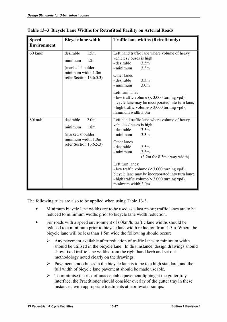
In provision of bicycle lanes on arterial roads, careful consideration is to be given to the choice of cycle and traffic lane widths. Table 13-3 provides guidance in achieving a suitable combination of lane widths that may provide a perception of balance in the amenity of both motorist and cyclist in the division of the available road pavement.
Before using the minimum widths in Table 13-3, careful assessment of aspects of the road that may adversely impact traffic lane width reduction is to be undertaken. Aspects to be considered include:
• Road geometry - sight lines through any curves.
• Speed environment.
• Surface roughness.
• Vehicle mix including heavy vehicle and bus usage.
• For right hand side lanes;
� Gutter width. � Drainage sump inlet intrusions. � Sight distance.
Design Standards for Urban Infrastructure
13 Pedestrian & Cycle Facilities 13-17 Edition 1 Revision 1
Table 13–3 Bicycle Lane Widths for Retrofitted Facility on Arterial Roads
Speed Environment
Bicycle lane width Traffic lane widths (Retrofit only)
60 km/h desirable 1.5m
minimum 1.2m
(marked shoulder minimum width 1.0m refer Section 13.6.5.3)
Left hand traffic lane where volume of heavy vehicles / buses is high - desirable 3.5m
- minimum 3.3m
Other lanes - desirable 3.3m - minimum 3.0m
Left turn lanes - low traffic volume (< 3,000 turning vpd), bicycle lane may be incorporated into turn lane; - high traffic volume(> 3,000 turning vpd), minimum width 3.0m
80km/h desirable 2.0m
minimum 1.8m
(marked shoulder minimum width 1.0m refer Section 13.6.5.3)
Left hand traffic lane where volume of heavy vehicles / buses is high - desirable 3.5m
- minimum 3.3m
Other lanes - desirable 3.5m
- minimum 3.3m (3.2m for 8.3m c'way width)
Left turn lanes: - low traffic volume (< 3,000 turning vpd), bicycle lane may be incorporated into turn lane; - high traffic volume(> 3,000 turning vpd), minimum width 3.0m
The following rules are also to be applied when using Table 13-3.
• Minimum bicycle lane widths are to be used as a last resort; traffic lanes are to be reduced to minimum widths prior to bicycle lane width reduction.
• For roads with a speed environment of 60km/h, traffic lane widths should be reduced to a minimum prior to bicycle lane width reduction from 1.5m. Where the bicycle lane will be less than 1.5m wide the following should occur:
� Any pavement available after reduction of traffic lanes to minimum width should be utilised in the bicycle lane. In this instance, design drawings should show fixed traffic lane widths from the right hand kerb and set out methodology noted clearly on the drawings.
� Pavement smoothness in the bicycle lane is to be to a high standard, and the full width of bicycle lane pavement should be made useable.
� To minimise the risk of unacceptable pavement lipping at the gutter tray interface, the Practitioner should consider overlay of the gutter tray in these instances, with appropriate treatments at stormwater sumps.

Design Standards for Urban Infrastructure
13 Pedestrian & Cycle Facilities 13-18 Edition 1 Revision 1
• Narrower bicycle lanes than those shown may be considered for short distances or "pinch points" (maximum 50m) with appropriate signage. This is where the cost of providing the minimum bicycle lane width is prohibitive (eg. a narrow bridge) and the loss of amenity may be balanced against the provision of a continuous facility.
• Minimum traffic lane widths may be reduced to an absolute minimum of 3.2m where kerb widening may be avoided and road geometry and surface roughness are considered acceptable.
• For right hand lanes, when the use of minimum traffic lane width is proposed, careful consideration should be given to gutter width, road geometry, sight distance, drainage sump inlet intrusions and surface roughness. Improvements are to be made where necessary before reducing the lane to minimum width.
• For further guidance on traffic lane widths also refer to Urban Road Design - Guide to the Geometric Design of Major Urban Roads, AUSTROADS.
13.6.5.3 Marked Shoulders
Where a bicycle lane to meet minimum standards cannot be installed within the available pavement width, and road widening is not feasible, consideration is to be given to the provision of a marked shoulder. A marked shoulder shall only be installed if it can be a minimum width of 1.0 metre, including any gutter tray.
A marked shoulder is preferred over a widened kerb-side lane on arterial roads and is to be provided on Main On-Road Routes. On Main On-Road Routes a marked shoulder will provide more defined continuity of the facility, albeit to a lower standard, as an interim measure until road widening can be completed in the long term.
Where a bicycle lane leads into a marked shoulder, a "bicycle lane end" sign is to be installed at the commencement of the marked shoulder.
To allow loose sealing aggregate (stone) to be removed by traffic action prior to marking, the marked shoulder may be installed several months after resealing has occurred.
13.6.5.4 Retrofit at intersections
Minimum requirements may be applied when retrofitting an on-road cycling facility at intersections. Continuity of any facility is to be maintained across intersections wherever possible, and this may also apply to marked shoulders. Continuity of bicycle lanes on Main On-Road Routes and maintenance of the cyclists right of way at intersections is to be considered a high priority, and is to be implemented whenever possible. In the context of signalised intersections this does not mean continuation of line marking through the intersection, but rather that continuity of facility be provided on each side of the intersection.
Where on-road cycle facilities are to be provided through an existing signalised intersection the position of existing detector loops is to be established. These may require reinstallation to function depending on any proposed lateral shift of lanes required for installation of on-road cycling facilities. The position of the detector loop should be marked after any resurfacing that obscures its position so that cyclists and vehicles can know where to position to trigger a phase change.
Use of head start and expanded storage boxes are to be considered for retrofit when upgrading signalised intersections. Retrofit of expanded storage boxes should always be considered where there is a signal controlled left turn lane, coupled with a high volume of left turning or through buses and heavy vehicles (refer Section 13.6.4.7).

Design Standards for Urban Infrastructure
13 Pedestrian & Cycle Facilities 13-19 Edition 1 Revision 1
13.6.5.5 Removal of redundant linemarking and RRPMs
When linemarking the reallocated road pavement, the treatment of areas of pavement that have had raised pavement markers and linemarking removed is to be carefully executed in order to remove any risk of confusion and discomfort to motorists.
The pavement is to be left smooth and with a surface texture similar to the existing pavement following the removal of such devices.
Care is to be taken to ensure all RRPMs are removed from within the bicycle lane or marked shoulder area as they can cause a danger to cyclists.
13.6.6 Coloured pavement treatment
13.6.6.1 General
Coloured pavement treatment should be considered for use on bicycle lanes at potential conflict points between cyclists and vehicles. The colour green has been adopted nationally for use to mark pavement defining cycle facilities. In the ACT this colour is defined as G15 Emerald Green, G16 Traffic Green or G23 Shamrock Green may be used as an alternative with consent from the Road Authority.
Use of the treatment should be consistent with NSW Bicycle Guidelines Section 8.1.3; however, it should be noted that all paths are shared paths in the ACT and use of coloured pavement treatment to mark off-road paths could be considered solely on designated cycle-only paths.
13.6.6.2 Warrant for use of coloured pavement treatment
Coloured pavement treatment should only be installed after careful consideration. This is because of the high cost of installation and maintenance and the risk that it may loose effectiveness as a warning device if over utilised. Approval by the Road Authority is required prior to installation of coloured pavement treatment at any location.
A warrant system has been developed to assist Practitioners in objectively identifying locations where coloured pavement treatment should be installed. The weightings and ratings for each criterion are shown in Table 13–4.
There are generally two cases where coloured pavement treatment should be considered. These include drop off parking locations and left turn slip lanes.
To calculate a score for a location, multiply the weighting by the rating assessed for each applicable criterion and sum together. For drop-off parking locations add together the products of criterion 1-4 and for left turn slip /exit lanes add together the products of criterion 1-3 and 5.
A score of 400 - 420 is an objective indicator that coloured pavement treatment may be warranted at the location.

Design Standards for Urban Infrastructure
13 Pedestrian & Cycle Facilities 13-20 Edition 1 Revision 1
Table 13–4 Warrant System for Coloured Pavement Treatments
No. Criteria
Weight
Rating
Rating
Rating
Common Criteria
1 Speed Environment
10 80 km/h 10 70 km/h 8 60 km/h 6
2 Visibility (Sight distance from vehicle travelling in left lane)
10 Less than 60 m
8 60 m to 100 m
6 More than 100 m
4
3 Traffic volume
a Vehicular traffic in the left traffic lane
5 3,000 vpd or more
10 Between 3,000 and 1,500 vpd
6 Less than 1,500 vpd
2
b Overall through vehicular traffic in all traffic lanes
5 10,000 vpd or more
10 Between 10,000 and 5,000 vpd
6 Less than 5,000 vpd
2
c Cyclist Traffic (future expected)
5 300 cycles per day or more
10 Between 300 and 100 cycles per day
6 Less than 100 cycles per day
2
AND Drop Off Parking
4 Adjacent drop-off parking areas
10 High use drop off area with more than 5 spaces
20 High use drop off with less than 5 spaces
17 Medium use drop off with less than 5 spaces
15
OR Left turn lane / exit lane
5a Vehicular traffic turning left turning left
10 3,000 vpd or more
10 Between 3,000 and 1,500 vpd
8 Less than 1,500 vpd
4
5b Left turn slip lane exposure length
10 50m or more 15 20m to 50m 8 10m to 20m 5
Typical arrangements for the use of coloured pavement treatments are shown on standard drawings DS13-21 and 22. Where coloured pavement treatment is installed at an exit ramp crossing, a rest rail arrangement is also to be installed.
Exposure length is defined as the length of bicycle lane that the cyclist can be regarded as having a high risk of conflict with vehicular traffic. Coloured pavement treatment should not generally be considered if exposure length is less than 10m for areas such as left turn slip lanes and adjacent drop-off parking areas
On roads with speed environments greater than 80 km/h, bicycle lane crossings of entry or exit ramps should not be considered. Exit ramp crossings can only be considered in 80km/h

Design Standards for Urban Infrastructure
13 Pedestrian & Cycle Facilities 13-21 Edition 1 Revision 1
environments where there are two traffic lanes in the direction of travel to allow vehicles to change lanes if a vehicle slows to give way to a cyclist. Refer to standard drawing DS13-04 for examples of exit ramp crossings.
Refer to NSW Bicycle Guidelines Section 7.5 for entry ramp crossings and entry and exit ramp signage arrangements.
Holding rail turn-outs should be provided where appropriate (for details refer to standard drawing DS13-04). Holding rails and turn-outs should generally be provided on exit ramps on roads in the urban area and may be omitted in rural areas.
13.6.7 Geometric design of off-road paths
Practitioners should be familiar with path geometric design requirements in terms of:
• Width.
• Gradient.
• Stopping sight distance.
• Change in grade.
• Horizontal curvature.
• Crossfall and drainage.
• Superelevation.
• Sight distance on horizontal curves.
• Safety at intersections and road crossings.
• Clearance to fences, poles and other obstructions.
• Clearance to trees.
• Clearance to road kerbs.
• Minimum verge widths.
• Transverse drainage measures to prevent silt and debris washing across paths.
• Access for disabled persons.
These requirements are contained in the Key Reference documents.
The location of paths in verges shall comply with the requirements of Chapter 4 Road Verges.
13.6.8 Path gradient
As a general principle, longitudinal gradients on paths for cycling should be as flat as possible. The potential hazard for cyclists due to high speeds on steep down grades is as significant as the difficulty of riding up the grade.
The requirements for the maximum gradient of Intermediate paths and Trunk paths are contained in GTEP 14. Such paths should not be located in verges where adjacent road gradients exceed those specified for the pathway. Alternatively, flatter routes could be investigated if this is a cost effective option.

Design Standards for Urban Infrastructure
13 Pedestrian & Cycle Facilities 13-22 Edition 1 Revision 1
For footpaths, the Key Reference documents do not give clear guidance on requirements for maximum gradient. Paths associated with building developments should comply with AS1428 Design for Access and Mobility. It is not always possible to apply this standard to all footpaths, eg. urban paths in verges with steep slopes. Footpaths may be provided for connectivity reasons in such circumstances but Practitioners should identify alternative routes for footpaths to optimise compliance for disabled users.
Table 13–5 identifies requirements for maximum gradients of pedestrian pathway routes.
Table 13–5 Footpath Gradients
Gradient Type Conditions Compliance with Access & Mobility
< 3.5% Footpath NIL Yes 3.5% to 5% Footpath 1.2m rests at 18m Yes 5% to 12.5% Footpath NIL No 12.5% to 37% (1:2.7) Ramp* NIL No > 37% Stairs NIL No
* Ramps are not suitable in urban environments.
Ramps and stairs shall comply with the requirements of AS1657 Fixed platforms, walkways, stairways and ladders.
Careful consideration should be given to treatment at the approach to crossings on steeper paths. Wherever possible, paths should be curved before a crossing to encourage cyclists to slow down and provide a strong visual marker that there is a change in conditions ahead. Appropriate landscape treatments that do not interfere with sight lines should then be installed to prevent shortcutting.
Landscape treatments should also be installed to prevent shortcutting where paths in public open space are curved as a means to reduce gradients. Use of rails, bollards or other devices to prevent shortcutting that may present a hazard to cyclists is not permitted.
13.6.9 Path cross section
The Key Reference documents provide the design requirements for the cross section details of various path types. Notwithstanding these requirements, paths shall comply with the following:
• For Intermediate and Trunk paths, the 500mm wide “shoulder” indicated in GTEP 14, should have the same crossfall as the path before transitioning to the batter slope.
• Root barriers should be installed on all pathways in close proximity to trees.
• The cross section details in standard drawing DS13-01.
Design Standards for Urban Infrastructure
13 Pedestrian & Cycle Facilities 13-23 Edition 1 Revision 1
13.6.10 Pavement design for paths
13.6.10.1 General
Practitioners should address the following parameters in the design of pavements for paths:
• Geotechnical conditions.
• Environmental conditions including drainage, existing and planned tree positions and species etc.
• Pavement materials.
• Likely frequency and type of vehicle loading.
• Location.
13.6.10.2 Flexible pavements
Flexible pavements with asphalt surfacing should be used for Trunk paths only. This treatment is generally not cost effective for narrower paths.
A geotechnical investigation of subgrade conditions is required for flexible pavement designs. This may take the form of an initial determination of subgrade material types and associated CBR values. Pavements could then be determined when actual subgrades can be visually examined during construction. "Work as Executed" plans should reflect actual pavement construction for the full length of the path.
Thin flexible pavements have often resulted in longitudinal cracking due, in the main, to unsuitable asphalt mixes and reflection of cracks in highly plastic subgrades. Practitioners shall adopt the pavement designs shown in standard drawing DS13-01. These have been developed to minimise longitudinal cracking in flexible pavements. Fine Gap Graded asphalt is required for use on paths, for details refer to Chapter 6 Road Pavements and Standard Specification - Part 4 Flexible Pavements.
13.6.10.3 Concrete Paths
It is preferred that concrete surface treatment is restricted to minor paths and intermediate paths.
The design of concrete paths is based on potential damage by vehicular traffic. Damage should be minimised by ensuring adequate protection of paths during development of adjacent residential and commercial areas. In addition to this requirement footpaths should be designed to generally withstand loads from larger vehicles. Concrete paths should be 100m thickness generally; however the thickness may be reduced to 75mm in verge locations where driveway positions are known.
In new sub-divisions or urban infill projects, reinforcement should be included in footpaths if they are to be constructed prior to the completion of building activity. Appropriate reinforcement is also to be included where manholes or other services pits are to be installed in the footpath. Careful consideration is to be given to the reinforcement design and joint locations to prevent any unplanned cracking of the footpath.
Practitioners shall adopt the pavement designs shown in standard drawing DS13-01. The optional treatments may be presented in design plans and selection could be based on contractor pricing. "Work as Executed" drawings should reflect the actual pavement construction adopted.

Design Standards for Urban Infrastructure
13 Pedestrian & Cycle Facilities 13-24 Edition 1 Revision 1
13.6.11 Root barriers
All paths that may be at risk of damage from tree root damage are to have root barriers installed (refer Chapter 22 Landscape Design - Section 22.8).
13.6.12 Paths and floodways
The protection of pedestrians and cyclists from flood events is a personal safety issue and Practitioners should consider crossings of floodways on a case by case basis.
In general, Trunk paths should, as a minimum, be located above the flood level of a storm event with a 2 year Average Recurrence Interval (ARI). Paths which are parallel to floodways should be as high as possible.
For retrofit of paths, protection to less than a 2 year ARI flood event may be appropriate with careful consideration of the following:
• Need for the path.
• Economic feasibility of providing 2 year ARI flood event protection.
• Suitable alternatives for when the path is unserviceable.
• Length of time path is unserviceable in the 2 year ARI flood event.
• Risk of use in the 2 year ARI flood event; danger of depth and velocity of flow.
Relaxation of the 2 year ARI flood protection will only be allowed with the endorsement of the Road Authority.
At grade crossings of floodways may be provided for footpaths and Intermediate paths under the following conditions:
• The alignment of paths is to be carefully examined at the planning stage. The number of floodway crossings should be optimised by utilising any nearby existing or proposed alternative high level crossings. This is to avoid, as far as possible, construction of crossings solely for paths.
• In situations when crossings for paths have to be provided across floodways:
a) at-grade crossings will be provided for Intermediate Paths and Minor Paths, and;
b) suitable structures that satisfy appropriate performance criteria for Trunk paths shall be provided.
• Where there is a definite desire line of travel that crosses a floodway for any type of path and a good quality high level crossing exists nearby (to which the cycleway or footpath would be connected), then the desire line can also be satisfied by an at-grade crossing.
13.6.13 Road crossings
The treatment of path crossings at roads and intersections shall comply with the requirements of the Key Reference documents. This includes the provision of pedestrian refuges, pram ramps and pram crossings. Refer to standard drawing DS3-02 for details of pram crossings and pram ramps.
Pram crossings are required at all points where any class of path meets any type of kerb (except flush).

Design Standards for Urban Infrastructure
13 Pedestrian & Cycle Facilities 13-25 Edition 1 Revision 1
Practitioners should note the complex safety and operational issues that arise where pedestrian and cycling routes cross certain types of intersections. VicRoads Cycle Note No.16 provides good guidance on the selection of off-road path crossing type.
Some key factors to be considered in the development of a suitable crossing design include:
• All path crossings. Ensure sight distances are adequate for all road and path users and that safe and convenient crossing locations are provided.
• Pedestrian / cycle refuges. Refuges may be required where traffic volumes are high (eg. Collector Streets). Refuges shall be 2.0m minimum width to cater for a bicycle (generally 1.75m long). On paths that have higher numbers of users, it may be necessary to increase the width of the island to provide greater storage capacity to allow for bicycles with trailers or tandem bicycles. The need for a refuge should be determined on a case by case basis addressing issues such as sight distances, vehicle speeds, proximity to primary schools etc. that will determine if a two stage crossing is warranted. Crossings at roundabouts should provide pedestrian refuge within the splitter islands and the crossing should be located 6m behind the hold line. This latter condition may not be possible in minor or mini roundabouts.
• Pedestrian crossings. GTEP 13 provides warrants for marked foot and pedestrian crossings. Practitioners should note the regulations in the Australian Road Rules with respect to use of marked foot and pedestrian crossings including the requirement for cyclists to dismount at these crossings.
• Path priority treatments. Use of marked foot and pedestrian crossings is not desirable on Main Community Routes with high cyclist usage, as a cyclist is required by law to dismount to cross. Use of a path priority crossing treatment such as "Give Way" or "Stop" sign crossings, which allow cyclists to ride across, should be considered in these instances. This crossing type should be considered on Main Community Routes when traffic volumes are low and peak path usage is greater than 100 users per hour. The crossing should be on a hump, and may be used in conjunction with other calming devices where appropriate, to slow traffic down in advance of the crossing. Use may also be appropriate when the crossing is part of a Local Area Traffic Management scheme.
• Signalised crossings may be considered where peak traffic volumes on the road exceed 1,000 vehicles per hour and peak path usage is greater than 100 users per hour. Bicycle crossing lights are to be provided on Main Community Routes. Signalised crossings should only be installed in appropriate locations and their function can be co-ordinated with other sets of traffic signals.
Rest rails at holding points are to be provided at crossings on Main Community Routes, Trunk paths, exit and entry ramp crossings and paths provided at roundabouts for diversion of on-road cyclists. Rest rails should be provided at any place where right of way is removed from a cyclist on Main Community Routes, including major driveways and local street crossings. To avoid confusion to both motorists and cyclists, rest rails should not be provided where a cyclist has priority. Refer to standard drawing DS13-04 for details of types and appropriate positioning of rest rails.

Design Standards for Urban Infrastructure
13 Pedestrian & Cycle Facilities 13-26 Edition 1 Revision 1
13.6.14 Use of Tactile Ground Surface Indicators
13.6.14.1 Accessible Pedestrian Networks
Tactile Ground Surface Indicators (TGSI) are to be provided on Accessible Pedestrian Networks (APNs) for people with vision impairment generally in town, group and local centres.
The objective of APNs is to provide logical and clear accessible walkway routes around prescribed areas to enable access for blind or visually impaired people to facilities in a safe and easy manner. This involves definition of continuous, clear paths of travel with access to all features such as designated car parking spaces, taxi ranks, set down areas, bus stops, building entrances and fixtures.
The mapping of Accessible Pedestrian Networks for the various town, group and local centres will be completed over time. An APN has been completed for Civic and details of this network and how to establish an APN is provided in the Civic Accessibility Study - Volume 3, Access Guidelines.
13.6.14.2 Indicator types
Strict design requirements are essential to ensure the consistency needed for correct interpretation of the warning that TGSI provide to people with visually impairment. The warning system comprises two types of TGSI:
• Warning indicators are a series of raised dots, which warn of an impending hazard. They are also used to indicate a “Change of direction”.
• Directional indicators are a series of raised lines, which provide directional orientation and are placed in a continuous run from the Accessible Pedestrian Network to the feature to which access is required.
Both warning and directional indicators must comply with AS 1428.4. In order to be serviceable in Canberra, with high UV and frost conditions, only ceramic, precast units or UV stable plastics are acceptable. 30% luminance contrast to background is required in all lighting and weather conditions.
Warning indicators are to be located in accordance with AS 1428.4.
Warning indicators are required on the Accessible Pedestrian Network as follows:
• All road crossings including pram crossings and pram ramps.
• Vehicular crossings with poor sight lines.
• Any overhead obstructions lower than 2m without a kerb or another barrier at least 150mm high.
• Where a sloping face intrudes into the clear path of travel at a point lower than 2m, 300mm out from base (Note: Such obstacles shall also meet the 30% luminance criteria).
• Top and bottom of stairs and ramps to a gradient of 1 in 20.
• At mid landing of stairs and ramps where handrail is not continuous the warning indicators need to be only 300mm in depth across the full width of the trafficable surface.

Design Standards for Urban Infrastructure
13 Pedestrian & Cycle Facilities 13-27 Edition 1 Revision 1
• At the end of or at stopping point of directional indicators or at change of direction of directional indicators.
Warning indicators are to be installed at bus stops in accordance with standard drawing DS13-03.
Directional indicators are required on the Accessible Pedestrian Network as follows:
• Mid block crossings.
• At T intersections.
• To bus timetables.
• To major signage (beacons).
• Across large open spaces where no other route or tactile cueing is available and where directional indicators are considered to be beneficial (eg to a point of entry to a significant public facility. Refer AS 1428.4 Clauses 2.2.4.1 and B3.3.
Examples of applications and details of installation requirements for warning and directional indicators may be referenced in Civic Accessibility Study - Volume 3, Access Guidelines and AS1428.4. Where there is conflict between the two reference documents AS1428.4 is to take precedence.
13.6.15 Provisions at structures
The reference documents provide details of requirements at structures such as underpasses, bridges, culverts, etc. Practitioners should consider the most cost effective measures to provide for safe, uninterrupted movement of pedestrians and cyclists at proposed and existing structures. In particular, Practitioners should note requirements for barriers and handrails, ramp gradients, sight distances, batters and clearances.
Refer to Chapter 7 Bridges for specific requirements at bridges. The following are the minimum provisions:
• Where on-road cycling facilities are provided such as a bicycle lane, wide kerbside lane or marked shoulder, this provision should extend across the bridge structure. If the bridge is on an arterial road, provision for a bicycle lane of appropriate width for the speed environment is to be allowed.
• Where a Trunk path is provided adjacent to the road and is required to be continuous along the road route, the path is to be continued across the bridge. The minimum clear widths are:
� Trunk Path 3.0m, bridge path 4.0m or 3.6m to allow 150mm pedal clearance to balustrades from smooth rail.
� Trunk Path 2.5m, if on a Main Community Route bridge path should be 4.0m, otherwise 3.4m or 3.0m is required to allow 150mm pedal clearance to balustrades from smooth rail.
� Footpath 1.2m, bridge path 1.8m. The above widths meet the requirements of clearances to guard rails and balustrades. It is generally not acceptable to divert a Trunk path from the bridge to dip through an underpass or low level crossing.
• Where a path is not provided, say on the median side of an arterial road, provide a safety zone 1.2m wide (kerb to guardrail) across the bridge.

Design Standards for Urban Infrastructure
13 Pedestrian & Cycle Facilities 13-28 Edition 1 Revision 1
Refer to Chapter 12 Public Lighting on requirements to ensure paths near and within structures are adequately illuminated for public safety and community surveillance.
13.6.16 Provisions at traffic calming devices
Local area traffic management treatments such as chicanes, raised platforms and mini roundabouts should be designed such that cyclists on the road are not forced or squeezed into unsafe situations. Either provide a separate protected route for cyclists or allow sufficient width for a car and cyclist to pass the device without hazard. Examples of treatments are indicated in GTEP 10, 13 and 14 and AS1742 Part 13.
13.6.17 End of journey facilities
Consideration must be given to design of adequate facilities at common destinations of cyclists and pedestrians so as to encourage bicycle and pedestrian usage.
Such facilities could include:
• Connectivity through provision of ramps and crossings to enable safe riding / walking to reach destination points within the destination node.
• Bicycle racks / parking areas.
• Bicycle lockers / storage.
• Seats.
• Shelter.
The Key Reference documents provide guidance on bicycle racks, storage lockers and other end of journey facilities. Careful consideration shall be given to the appropriate placement of these facilities with regard to public transport connectivity, security, passive surveillance and proximity to destination points.
13.7 Signage
13.7.1 General
Signage for pedestrians and cyclists is to be sited so as to be visible and legible with particular regard to the eye height and sight lines of these users. Signage should be placed as low as possible to permit good visibility by pedestrians and cyclists. Wherever possible signage should be placed to maximise visibility at night through use of existing lighting.
Signage is to be placed to not be ambiguous to road users and minimise any risk of confusion with road signage. Directional signage for off-road paths is not be co-located with road directional signage.
Unless approved by the Road Authority directional signage for pedestrians and cyclists is to be restricted to the Main Routes network as illustrated on standard drawing DS13-11.
13.7.2 Main Routes signage
13.7.2.1 Royal blue on white convention
To enable cyclists and pedestrians to easily identify Main Community routes, signage is to be in royal blue on white instead of black on white. This applies to the (main) shared path sign
Design Standards for Urban Infrastructure
13 Pedestrian & Cycle Facilities 13-29 Edition 1 Revision 1
which will allow for use as a reassurance sign, and differentiate Main Community Routes from other Trunk paths.
Connector Routes are to be signed in royal blue on white whereas bicycle lanes will be signed in black on white. This may be used as a guide by the cyclist to differentiate the level of skill and experience that may be required to feel comfortable using a particular cycling facility. Accordingly, a royal blue on white cycle only sign represents a facility such as a Connector Route applicable more for recreational and family cyclists, whereas black on white cycle only sign represents bicycle lanes generally on arterial roads.
13.7.2.2 Directional signage principles
The principles for design of directional signage are based on a hierarchy of routes and destinations. However, the development of the route network and evolution of planning over a number of years in the ACT has resulted in a variety of network characteristics that preclude the formulation of rigid signing rules. The application of a flexible and rational approach, within the established framework, is, therefore, an important part of guide-sign planning and design.
It is also presumed that a signage system cannot cater for the entire length of most journeys and that some additional form of aid such as a cycling and walking map, street directory, or verbal/written instructions remain a necessity for most travellers.
Destinations for which guide signs are provided include urban destinations, services and tourist attractions.
Destinations for signage are divided into two categories:
• Primary Destinations, and
• Secondary Destinations.
13.7.2.3 Primary destinations
There are seven primary destinations nominated for the Canberra region that shall be signed as follows:
• Belconnen
• City
• Gungahlin
• Queanbeyan
• Tuggeranong
• Weston Creek
• Woden
The extent of influence for each primary destination is shown on standard drawings DS13-31 to 37 with direction arrows at key decision points (refer Section 13.7.3.3) to indicate the route to be signed.
13.7.2.4 City and Town Centres
Belconnen, Gungahlin, Tuggeranong and Woden are defined as Town Centres as they are areas subject to Commercial A and B land use policies in the Territory Plan. Within two kilometres of the centre of the four listed Town Centres the destinations shall be signed as

Design Standards for Urban Infrastructure
13 Pedestrian & Cycle Facilities 13-30 Edition 1 Revision 1
“Town Centre”. The two kilometre radius is shown on standard drawings DS13-31, DS13-33, DS13-35 and DS13-37.
Civic is also defined as a Town Centre however it is always to be signed as City.
13.7.2.5 Secondary destinations
Secondary destinations have a lower extent of influence than primary destinations and are generally signed within close proximity of the destination.
The following represents details of how secondary destinations are to be signed:
• Suburban Shops
Suburban Shops are signed from Main Community routes only with local area signage in accordance with Section 13.7.3.4.
• Group Centres
The group centres are to be signed as: “Calwell Centre”, “Charnwood Shops”, “Chisholm Centre”, “Cooleman Court”, “Curtin Shops”, “Dickson Shops”, “Erindale Centre”, “Hawker Shops”, “Jamison Centre”, “Kaleen Plaza”, “Kambah Village”, “Kingston Shops”, “Kippax Centre”, “Lanyon Marketplace”, “Manuka Shops”, “Southlands” and “Wanniassa Shops”.
• Industrial Areas
The main industrial areas are to be signed as: “Fyshwick” and “Mitchell”. Hume and Belconnen are minor industrial areas and the road signage is considered sufficient.
• Employment Areas
The employment areas are to be signed as: “Bruce”, “Russell”, "Airport" and “Parliamentary Zone”. Symonston, Symonston (North) and Symonston (West) are not proposed to be signed.
• Tertiary Educational Institutions
The tertiary educational institutions are to be signed as: Australian National University – “ANU”; University of Canberra – “UC”; and Canberra Institute of Technology – “CIT”; The Australian Defence Force Academy, Australian Catholic University, National Theological Centre and Australian International Hotel School are not proposed to be signed.
Other destinations not listed above may be signed with the approval of the Road Authority.
13.7.3 Main Community Routes signage
13.7.3.1 General
A higher standard of signage is to be provided on Main Community Routes. Typical layouts for signage placement are shown on standard drawing DS13-13.

Design Standards for Urban Infrastructure
13 Pedestrian & Cycle Facilities 13-31 Edition 1 Revision 1
13.7.3.2 Main Community Route signs
Main Community Routes are to be marked with a main shared path sign that is royal blue on white, instead of the Australian Standard shared path sign that is black on white (Sign DS13-12/2). Trunk paths are to be marked with standard black on white shared path signs (Sign R8-2A). The DS13-12/2 sign is also to be used as a re-assurance sign on Main Community Routes, and is to be installed in conjunction with all key decision point signage (refer below) and at other decision points. A decision point is defined as any point along a Main Community Route where the user may require directional reassurance to continue on the signed route. This includes junctions with paths that may appear to be the same hierarchy as the Main Community Route.
A direction arrow sign DS13-12/3 is to be installed with the DS13-12/2 sign at other decision points such that directional signage (including key decision point and re-assurance signage) should be at a maximum spacing of not more than 1 kilometre.
Details of signs DS13-12/2 and 3 are shown on standard drawing DS13-12.
13.7.3.3 Key decision point signage
A key decision point is defined as the intersection of two or more Main Community Routes. All key decision points shall have a signed destination(s) for each route leg and shall generally include a primary destination for each route.
Key decision point signage shall include a Route Name (refer Section 13.7.3.6) and a shared sign path (DS13-12/2) as well as the direction sign. The direction sign shall include the destination name, a direction arrow and distance to the geographic centre to the nearest kilometre. The defined geographic centre for each primary destination is shown on standard drawings DS13-31 to 37. Refer to standard drawing DS13-12 for sign details and standard drawing DS13-13 for a typical signage layout.
The Main Community Route network has evolved such that more than one Main Community Route may lead to the same primary destination from a key decision point. The Practitioner shall refer to standard drawings DS13-31 to 37 to establish which legs at the key decision point have nominated primary destinations. Where a primary destination is not indicated on standard drawings DS13-31 to 37 a secondary destination shall be signed.
The secondary destination to be included on the key decision point signage will typically be one of the nominated destinations listed in Section 13.7.2.5, or if not applicable, the suburb adjacent to where the next key decision point is located. If the route has no further key decision points because it ends without passing through another key decision point, the suburb that the Main Community route ends in shall be signed.
Once a secondary destination is signed that destination shall be continuously signed at all key decision points along the route until that destination is reached. This may require more than one destination to be shown on a leg.
Where a Main Community Route meets a path that is not a Main Community Route and there may be some ambiguity as to the direction of the Main Community Route, a main route shared path sign (DS13-12/2) and directional arrow (DS13-12/3) shall be erected for directional re-assurance in accordance with Section 13.7.3.2.
13.7.3.4 Start signs
A start sign is to be provided where a Main Community Route exits from the City and Town Centres defined in Section 13.7.2.4. The sign is intended to advise users of the distance to the primary destinations that are on or lead from the signed Main Community Route. The sign

Design Standards for Urban Infrastructure
13 Pedestrian & Cycle Facilities 13-32 Edition 1 Revision 1
shall be located based on site observations and shall be discussed with the Road Authority prior to detailed design. Details of the start sign are shown on standard drawing DS13-12.
13.7.3.5 Local area signage
Local area destination signage may be provided at the intersection of a Main Community Route with a path of lower significance that provides the shortest link and leads directly to a secondary destination as defined in Section 13.7.2.5. The sign is to include the local area destination name and distance to the nearest kilometre, or if under 1 kilometre to the nearest 0.1 kilometre. Refer to standard drawing DS13-12 for sign details.
Local area signage is to be placed on a Main Community Route only once for each direction of travel for each secondary destination. Depending on the path network leading from the Main Community Route these signs may be positioned at a single path junction (back to back) or at two separate path junctions where shorter routes exist from each approach direction. The sign should be placed on a path where a direct route to the destination exists, and additional direction signage is not required. Refer to standard drawing DS13-14 for a typical signage layout.
Other factors with regard to the anticipated user groups should also be considered in the choice of path to be marked with a local area destination sign. These factors include:
• Quality of path.
• Complexity of route.
• Users with regard to disabled access.
• Pram ramp provisions.
13.7.3.6 Route name signs
Route name signs are to be installed in conjunction with Key decision point signage (refer standard drawing DS13-12 for details).
Not all routes may be named and in the case of an unnamed route, signs should be placed on the pole support such that the route name sign may be installed in the future. Route names may be obtained from the Road Authority.
13.7.3.7 Street name signs
Street name signs should be provided at street crossings on Main Community Routes if not visible from the crossing point. This is to allow the user to locate themselves on their journey. This requirement may be relaxed if street signs are visible within 50 metres of the crossing.
The street sign should be installed parallel with the street crossed, in a location clearly visible and as close as possible to the path crossing. An example street crossing is included on standard drawing DS13-13. The sign should be installed on existing poles such as light poles or share with other signage wherever possible.
13.7.3.8 On-road cycling connection direction sign
At connection points from Main Community Routes to bicycle lanes an on-road cycling connection direction sign is to be installed. This sign is detailed on standard drawing DS13-12 and a typical signage layout is provided on standard drawing DS13-14.

Design Standards for Urban Infrastructure
13 Pedestrian & Cycle Facilities 13-33 Edition 1 Revision 1
13.7.4 Connector Routes signage
13.7.4.1 General
Connector Routes are to have continuous directional signage to allow a cyclist to follow the route to its destination through required turns at road intersections and connecting off-road path links as necessary. A combination of Connector Route direction signs and re-assurance signs are to be provided to achieve this aim.
Typical layouts for signage placement are shown on standard drawing DS13-13 and 14.
13.7.4.2 Connector Route direction sign
Connector Route direction signs are to be placed at decision points along the route at a maximum spacing of not greater than 1 kilometre.
Connector Route direction signs are to show the primary destination name as listed in Section 13.7.2.3 and distance to the nearest kilometre, or if under 1 kilometre to the nearest 0.1 kilometre. Other destinations may be appropriate if they represent the end point of the route. Details of the Connector Route direction sign are shown on standard drawing DS13-12.
13.7.4.3 Connector Route re-assurance sign
The Connector Route reassurance sign (sign DS13/12-1) is to be installed at every decision point where a Connector Route direction sign is not installed. This includes clear direction on to and along any off-road linkages that may make up the Connector Route.
Details of sign DS13-12/1 are shown on standard drawing DS13-12.
13.7.4.4 Connector alternative route direction sign
The Connector alternative route direction signs are to be installed where a Connector Route intersects a Main On-Road Route or a Main Community Route.
Details of the Connector alternative route direction sign are shown on standard drawing DS13-12. A typical layout illustrating the proposed usage of this sign is shown on standard drawing DS13-14.
13.7.5 On-road cycling signage
On road cycling signage is to be in accordance with GTEP14 and the other Key Reference documents.
There are no special signage requirements for Main On-Road Routes except as defined in Section 13.4.4. Bicycle lane signs are generally to be a minimum B size and a minimum C size in 80km/h speed zones.
Where a bicycle lane passes by, over, under or parallels a Main Community Route and there is a connection path provided to enable passage of a cyclist to the off-road path, a main shared path sign (sign DS13/12-2) and a direction arrow (DS13/12-3) are to be installed to indicate the linkage between facilities.
13.7.6 Behavioural signage
Behavioural signage is of an advisory nature and is generally only to be used on Main Community Routes with the consent of the Road Authority. Behavioural signage is to be in accordance with the NSW Bicycle Guidelines Section 6.6.

Design Standards for Urban Infrastructure
13 Pedestrian & Cycle Facilities 13-34 Edition 1 Revision 1
13.7.7 Rural training circuit signage
Where there are circuits or particular sections of road used on a regular basis by training and racing cyclists the installation of rural training circuit signage in accordance with VicRoads Cycle Note No. 6 is to be considered. The signage is only to be used with the consent of the Road Authority with consultation with the ACT Veteran and Canberra Cycling Clubs.
13.8 Glossary Absolute Minimum: A dimension below which the treatment cannot be used under any
circumstances.
Arterial Road: A road with a prime function to provide for major regional and inter-regional traffic movements.
AUSTROADS: The national association of road traffic authorities in Australia. Formerly NAASRA (National Associations of Australian State Road Authorities).
Bicycle Lane: A lane designated for the exclusive use of cyclists marked in accordance with Australian Road Rule 153 and GTEP 14 Figure 9-20. Referred to as Exclusive Bicycle Lane in GTEP14.
Bicycle / Car Parking Lane: A lane combination used on roads where one section is designated for the exclusive use of cyclists and the other for motor-vehicle parking.
Collector Road: A road with a prime function to distribute traffic between arterial roads and local streets.
Connector Route: main cycle route that utilises local and minor collector streets and off-road path linkages to provide connections in the Main Community Path network where it may not be feasible to provide a trunk path.
Design Speed: A speed unlikely to be exceeded by most cyclists or drivers as appropriate, and not less than the 85th percentile speed. It is used to co-ordinate sight distance, radius, super-elevation and friction demand for elements of the road or path so that cyclists or drivers negotiating each element will not be exposed to unexpected hazards.
Desirable: The dimension provided in tables specifying the width of bicycle lane or path treatment facilities, which is normally used. For new construction it is a requirement to use this dimension.
Desire Line: Route chosen by cyclists (or other road or path users if relevant) irrespective of the presence of a route, path or other facility..
Exposure Length: the length of bicycle lane, typically at a sliplane, in which the cyclist can be regarded as having high risk of conflict with vehicular traffic.
Footpath: An area open to the public that is designated for, or has as one of its main functions, use by pedestrians, but which does not include a shared use path.
Gradient: The longitudinal slope of a road or path, usually represented as the ratio of a one metre vertical rise to the horizontal distance (eg. 1:50), or expressed as a percentage (eg. 2%).
Gifted Assets: Infrastructure constructed by a private developer to be given to the ACT Government to own and maintain.

Design Standards for Urban Infrastructure
13 Pedestrian & Cycle Facilities 13-35 Edition 1 Revision 1
Main Community Route: Off-road path, nominally a trunk path, that is part of the Main Routes network with a defined higher level of amenity than a trunk path.
Main On-Road Route: An on-road cycle facility that is part of the Main Routes network.
Main Routes Network: Network of on-road cycling, off-road paths and connector streets as defined on standard drawing DS13-11.
Marked Shoulder: Area of smooth road pavement with a minimum width of 1.0 metres to the left of an edge line that a cyclist may use.
Percentile Speed: Speed at or below which the nominated percentage (eg. 15, 50, 85) of vehicles are observed to travel under free flow conditions.
Performance Criteria: General statements that provide a basis for judging whether a stated intent has been met.
Pinch Points: a length of bicycle lane or other cycle facility (maximum 50m) that is narrower than the defined minimum width.
Planning Authority: ACT Government agency responsible for planning.
Rest Rail: A rail used by cyclists to assist them to avoid having to remove / detach their feet / shoes from their pedals, so they can wait in a ready position (for cycling) at intersections.
Road Authority: ACT Government agency responsible for ownership and maintenance of road and path infrastructure.
Road Reserve: Land comprising the road and adjoining nature strips.
Sealed Shoulder: Refers to the sealed edge of roads outside of the travelled carriageway (the shoulder) of roads where cyclists might be expected to ride. It is delineated by an edge line applied between the sealed shoulder and the travelled section of a carriageway. The treatment is almost invariably associated with unkerbed roads, and is often applicable to rural roads.
Shared Use Path: A path open to the public that is designated for, or has as one of its main functions, use by both cyclists and pedestrians, but which does not include a separated footpath or a footpath adjacent to a road.
Speed Environment: Effectively the 85th percentile speed for a particular road or path section.
Squeeze Point: A narrowing in a travelled section of a path or road that may be hazardous to cyclists who are forced to move nearer to or into an adjacent stream of traffic.
User Groups: Pedestrians and cyclists are made up of different groups of users that have different requirements and needs. Pedestrian user groups include walkers, joggers, people pushing prams or strollers and those using wheelchairs, both motorised or non-motorised. Cyclist user groups include primary and secondary school children, family groups / recreational riders, commuters, neighbourhood / utility riders, and touring and training cyclists (refer GTEP 14 and VicRoads Cycle Note No.7).
Verge: Public land within a Road Reserve between the road kerb and the property boundary.
Wheeled Recreational Devices: include roller blades, roller skates, a skateboard or similar wheeled device.

Design Standards for Urban Infrastructure
13 Pedestrian & Cycle Facilities 13-36 Edition 1 Revision 1
Wide Kerbside Lane: A motor traffic lane free of parked cars, and of sufficient width to permit cyclists and other vehicles to travel along a road within a lane generally located at the left side of a road, without significant impact on each others paths. May be associated with a two-way / two-lane road or a multi-lane road.
13.9 Standard Drawings The standard drawings relevant to Pedestrian and Cycle Facilities are:
Title Drawing Number
Path Standard Details DS13-01
Vehicle Restriction Detail DS13-02
Bus Stop Standard Details DS13-03-1
Bus Stop Standard Details DS13-03-2
Cycle Rest Rail Details DS13-04
Onto Off Road Path Connection Details DS13-05
Main Community Route Driveway Crossing DS13-06
Main Routes Network (Proposed and Existing) DS13-11
Main Routes Guide Signs Standard Details DS13-12
Sign Location Layouts - 1 of 2 DS13-13
Sign Location Layouts - 2 of 2 DS13-14
Coloured Pavement Treatment DS13-21
Coloured Pavement Treatment at Exit Ramps. DS13-22
Signage Extent of Influence - Belconnen DS13-31
Signage Extent of Influence - City DS13-32
Signage Extent of Influence - Gungahlin DS13-33
Signage Extent of Influence - Queanbeyan DS13-34
Signage Extent of Influence - Tuggeranong DS13-35
Signage Extent of Influence - Weston Creek DS13-36
Signage Extent of Influence - Woden DS13-37