Embed Size (px)
Citation preview
DRAFT
City of Plant CityTechnical Service Manual
___________________ Brett J. Gocka, P.E.
City Engineer

Forward
The procedures and provisions set forth in this manual shall apply to any development project, lot, parcel or tract of land within the City limits. These procedures and provisions were developed based upon the latest technical standards from the Florida Department of Transportation, American Association of State Highway and Transportation Officials, Southwest Florida Water Management District, State of Florida Department of Environmental Protection, and the American Society of Civil Engineers.
These standards represent minimum standards for development required to protect the public health, safety and welfare of the citizens of the City of Plant City.
This manual is not meant to be totally restrictive, nor represent the only acceptable method of design. The purpose is only to provide minimum acceptable standards of construction and promote uniformity. The requirements should be reviewed annually to provide consistency with State and Federal requirements.
It is recognized that these standards will not be applicable to every situation that may arise on a particular project. It is also recognized that all specific design or construction problems may not be recognized in the review of the project prior to the construction approval. The City Engineer may make modifications to these standards where the application of the standards to a specific situation will result in an unusual and unreasonable hardship; provided however, that the City Engineer determines that such modification is inconformity with the spirit and intent of applicable ordinances
i
Chapter 1
A) Application Requirements
All construction plans shall be submitted to the City of Plant City in the required number of copies and shall conform to specifications and requirements of all State, Federal and City regulations. Construction plans shall be prepared and certified for all improvements by a state-registered professional engineer. All revisions shall be prepared and submitted as required for original plans in complete sets only. Construction plans shall include the following:
1. A legal description of the property, including the citation and general description of any existing easements, covenants or other restrictions affecting the use and development of the property existing at the time of submission.
2. Existing site conditions shall reflect the following:
a. Location, size, elevation and other appropriate descriptive information of existing facilities and features and the point of connection to proposed facilities and utilities. All water bodies shall show approximate seasonal high and low water elevations.
b. Topographic contours at one foot intervals, based on the NAVD 88 vertical datum extending 100 ft beyond the property boundary and NAD83 1990 adjustment.
c. Flood elevation data and flood zones delineated.
d. Site specific soil survey data, prepared by a registered engineer, indicating all soil classifications and water table elevations.
e. A certified boundary and topographic survey performed in accordance with Chapter 61G17-6, F.A.C., pursuant to Chapter 472.027, F.S., which accurately depicts the actual location of any existing roadway accesses, site improvements, visible encroachments, flood hazard areas and jurisdictional wetlands on site. The survey shall be prepared at a scale sufficient to show all details of the site. Preferably 1” = 20’.
f. A wetland survey certified by the Southwest Florida Water Management District or the Environmental Protection Commission of Hillsborough County.
g. All existing utility including the location of any on site wells.
h. Certification or documentary evidence that no environmental contamination exists on the proposed site.
3. Subdivision design shall conform to the following:
a. Proposed grading or spot elevations at sufficient detail to define the proposed drainage patterns; the subject parcel as well as adjacent areas to be affected shall be shown.
b. Typical lot layout, lot, block and street design showing radii of all curves and corners; lot dimensions; and district setbacks.
c. Plan and Profile sheets depicting existing and proposed elevations, grades and treatment of all roads and intersections.
d. Cross sections of all street intersections.
e. Plans and profiles depicting the location and typical cross sections of all required improvements.
f. Details illustrating connections to existing and proposed utility systems.
g. Location of fire hydrants and evidence fire flows can be met as outlined by Section 603 of the NFPA 101.
h. Drainage map, including the entire area to be developed and adjacent areas to be affected by such drainage. Disposition of storm waters should be shown.
i. If variable width rights-of-way are proposed, roadway and ditch cross sections, at maximum intervals of 100 foot, may be required. However, if conditions warrant, cross sections may be at intervals less than, or greater than, 100 feet, as determined by the City Engineer.
j. List of bench marks on City NAVD 88 datum giving location and elevation. There shall be at least one bench mark in every 1,000 feet horizontal in the subdivision. Horizontal control shall be set to NAD 83 1990 adjustment.
k. All plans shall contain a note requiring conformation with current FDOT specifications for material quality and workmanship.
l. The proposed location of any proposed walls or fences shall be outside of road rights-of-way.
m. There shall be no areas without designations on construction plans. Areas shall de designated lots, tracts or right-of-way.
n. Construction plans shall show location and types of proposed lot lines, uses, facilities, easements, open space areas, typical structure dimensions, parking areas, landscaping, buffers, vehicle circulation and minimum setbacks.
o. Construction plans shall show the approximate location of all adjacent abutting development within a maximum of 100 feet including, phases, land use designations, and existing structures.
4. Other information submitted in graphic and narrative form shall be as follows:
a. All storm water calculations and descriptions, prepared by a state registered engineer, needed to show compliance with requirements of the County, State and water management districts.
b. Type and location of any erosion and sedimentation controls which will be used during the construction process.
c. Copies of permits, applications and approvals from all applicable regulatory agencies. If permit applications are submitted, the construction plan approval shall be based upon the assumption that the applicant will obtain the necessary permit approvals required and notation of the assumption shall be placed on the construction plans.
d. Identification of all wetland encroachments.
e. Calculations for storage lane capacity, where applicable.
5. A draft of any proposed protective covenants, property owner association articles of incorporation and bylaws.
B) Exemptions
The creation of two lots provided there is no dedication or construction of new roadways and provided no lot or parcel of land is created entirely in wetland, floodway or flood plain shall be exempt from meeting the stormwater requirements of this manual.
Chapter 2
A) Permits
1. Upon approval of the application for construction, the City Engineering Department shall issue a permit for construction. The duration of the permit shall not be greater than 5 years.
2. The permit shall be construed as a license to proceed with the work as approved and not as authority to violate, cancel, alter or set aside any of the provisions of this document or City Ordinance, nor shall issuance of a permit prevent the Building Official or City Engineer from thereafter requiring a correction of errors in plans, construction, or violations of this code. Every permit shall become invalid unless the work authorized commences within (6) six months of issuance, or if the work authorized by such permit is suspended or abandoned for a period of (6) six months after the time the work is commenced.
3. The permit may be extended for two (2) time extensions not more than ninety (90) days each provided the total time including any stoppages does not exceed five (5) years. All extensions shall be submitted in writing along with a justifiable cause to the City Engineer and Building Official.
4. For the purposes of this section the following definitions shall apply:
a. Commenced shall mean the installation of utilities.
b. Abandoned shall mean no work has been preformed on site for a period of 96 hours or an approved foundation inspection has not been performed.
5. No construction may commence until plans have been approved by the City Engineer and a preconstruction meeting held (requirement maybe waived by City Engineer).
a. It shall be the responsibility of the developer/owner to coordinate all utilities concerning the proposed development. All utilities shall have been provided a copy of the approved construction plans prior to the preconstruction meeting. Further it shall be the developers responsibility to coordinate utility representatives at the preconstruction meeting. The following utility representatives shall be notified, Tampa Electric Company, local gas utility, Brighthouse, and Verizon.
b. The developer shall provide 6 sets of final plans for construction at the preconstruction meeting. These plans are for distribution to the contractor, developer and engineer of record.
c. The engineer of record and the developer shall be in attendance at the preconstruction meeting. If the engineer of record is not in attendance the City may elect to cancel the preconstruction meeting and reschedule the meeting at a time when the engineer of record may be in attendance.
6. Prior to construction it shall be the contractors responsibility to notify Sunshine State One-Call by dialing 1-800-432-4770 at least 72 hours prior to the start of work.
7. If any work is proposed to take place along any or impacting any Florida Department of Transportation right of way. Separate notification of work commencement must be made to the Florida Department of Transportation local office.
8. Preliminary ditching, clearing and grubbing, and earth moving incidental to the site preparation may be performed with approval of the City Engineer prior to construction plan approval. However, no impacts to wetlands, floodplains and drainage features shall be authorized prior to construction plan approval.
9. Bonding required as part of final plat approval must be secured prior to any impacts to the proposed site and may be used for restoration in the event the project is not approved or the site is not constructed.
10. Any land alteration which takes place prior to construction plan approval must be approved by the City Engineer.
B) Approved Plans
1, All approved plans shall be stamped by the Engineering Department. Plans not stamped shall not be used for construction.
2. The contractor shall maintain an approved set of project plans on site at all times during the course of construction from the first day of the project until final acceptance of the project. These plans are for the use of all contractors, sub-contractors, vendors and City personnel during construction and must be available for their use in the performance of inspections. Failure to comply with this requirement is a breach of the permit requirements and is justification for suspension of the work and\or revocation of the permit by the City Engineer.
3. Revisions to the approved plans by the owner\contractor shall be submitted to the City of Plant City Engineering Department and all applicable government agencies for approval prior to construction of the revision. Non-compliance will cause the revisions to be null and void and will result in non-acceptance of the work in place. Any and all revisions to the approved plans shall be submitted by the engineer of record to the City Engineer and approval obtained prior to implementation of the revisions. It is not the policy of the Engineering Department to suspend work due to revisions of the plans resulting from varying field conditions, field changes due to conflicts with existing facilities, or other normal occurances. However it is the sole responsibility of the contractor\owner\developer to submit revised plans to the Engineering Department for approval.
C) Shop Drawings
1. Shop drawings for all materials to be accepted by the City shall be approved by the City. The contractor shall submit shop drawings approved by the engineer of record for approval by the City.
2. No materials shall be placed on site that have been reviewed and approved by the City of Plant City.
D) Final Acceptance

1. The developer shall request in writing that the development is complete and ready to be accepted by the City. The City shall inspect the site and determine completeness. Acceptance of the project is based upon the projects conformance with the approved plans. If the City finds all improvements have been completed then the developer shall submit a warranty bond that is 10% of the original bonded amount. Construction not conforming to the approved plans will not be accepted until all revisions are approved by the City of Plant City and all other appropriate governmental agencies.
2. In order to avoid close out delays the following items must be submitted prior to scheduling a final inspection:
a. As built drawings and Autocad filesb. Payment of any inspection fee’sc. Letter clearing any notice to owner issuesd. Itemized construction costs e. Engineer certificationsf. Health Department clearanceg. FDEP clearance for wastewater collection systemh. All test results submitted to the Engineering Department
3. Upon completion of a final inspection a punch list of items shall be generated and delivered to the owner and\or contractor. The City will not accept the project until all punch list items have been resolved to the City Engineer’s satisfaction.
4 Prior to acceptance of the improvements, the engineer of record shall supply as-built drawings in accordance with the City as-built drawing requirements indicated in this manual.
5 The City of Plant City shall have the right to inspect and approve materials and/or phases of work. Final inspection and acceptance of work by the City of Plant City shall be obtained in writing prior to acceptance of the improvements by the City.
6 No certificate of occupancy shall be issued until the project has been accepted by the City of Plant City.
Chapter 3
A) Inspection and Certification
Approval of construction plans by the City in no way constitutes a waiver of health and safety standards nor Federal and State laws. The health and safety of the citizens of Plant City is a major concern to the City and takes precedence over any of the approved plans and/or agreements that may be in effect concerning the project.
1. The engineer of record shall be responsible for the inspection during construction to ensure that the project is constructed in accordance with the approved plans and specifications.
2. The City inspector shall determine the time, location and sampling technique for all samples taken in the field. The sampling schedule listed below shall be used to determine field testing requirements.
3. The City inspector does not have the authority to halt construction of a project. Any project stoppages shall be noticed by the City Engineer to the contractor and developer.
4. If construction is to occur outside of the City regular work hours the contractor may request the presence of a City inspector outside of regular work hours providing:
a. The contractor shall provide the City with 48 hours notice prior to the work commencing.b. The City Engineering Department has the available staff to provide the requested inspections.c. The contractor pays the cost (overtime rate plus the cost of overhead) of having the required City
personnel on site for the inspections.d. The number of inspectors and personnel performing the inspection shall be determined by the City
Engineer.
5. Changes in plans or specifications substantially affecting the conformance to standards or performance of systems must be requested by the engineer of record during construction prior to the implementation of the changes. Such changes shall be requested in writing and approved by the City Engineer. Substantial changes shall include:
a. Any changes to contract specifications.b. Modifications to City standard details.c. Changes to permitted plans and specifications approved by the City Engineer.
6. For any area where a tested sample is deficient from the specifications, the area shall be re-worked and re-tested at no cost to the City, until a passing test is obtained. Test results for all required tests, including re-tests showing passing results for all deficient areas, along with a certification by the test lab that the materials tested meet the specifications shall be submitted to the engineer of record and the City Engineer prior to the commencement of the next construction phase.
7. As-builts shall be prepared according to the City of Plant City standards for as-built drawing submittals.
8. The following items represent the minimum items the City Engineering Department shall inspect:
a. Gravity Sewer Systems
1. House lateral connections2. Commercial lateral connections3. Pipeline installations and materials4. Manholes and cleanouts5. Reconnections and/or renovations6. Materials testing7. Line testing
b. Force Mains
1. Pipeline installation and materials2. Air release valves3. Structures4. Pressure tests5. Soils testing
c. Pump Stations
1. All structure installation and materials2. Pipes and connections3. Mechanical equipment and installation4. Instrumentation equipment and installation5. Electrical equipment, materials and installation6. Auxiliary power generators and installation7. Startup of station to include the warranties and operation and maintenance manuals
d. Stormwater Management Systems
1. Pipeline installation and materials2. Structure installation and materials3. Retention/detention facilities4. Swales5. Fences
e. Roadways and Parking Areas
1. Base and sub-base materials and installation2. Asphalt or concrete surfaces installation and materials3. Curbs4. Sidewalks5. Handicap ramps and facilities
6. Curbs and gutters7. Traffic control signage and pavement markings8. Maintenance of traffic plans (vehicular and pedestrian)9. Clearzone
f. Solid Waste Facilities
1. Dumpster pads installation and materials2. Location3. Enclosures
g. Restoration
1. Sodding of disturbed right of way2. Sodding of retention\detention basins
h. Reclaimed Water
1. Pipeline installation and materials2, Structures3. Pressure tests4. Soil tests
i. Potable Water
1. Pipeline installation and materials2, Structures3. Pressure tests4. Soil tests
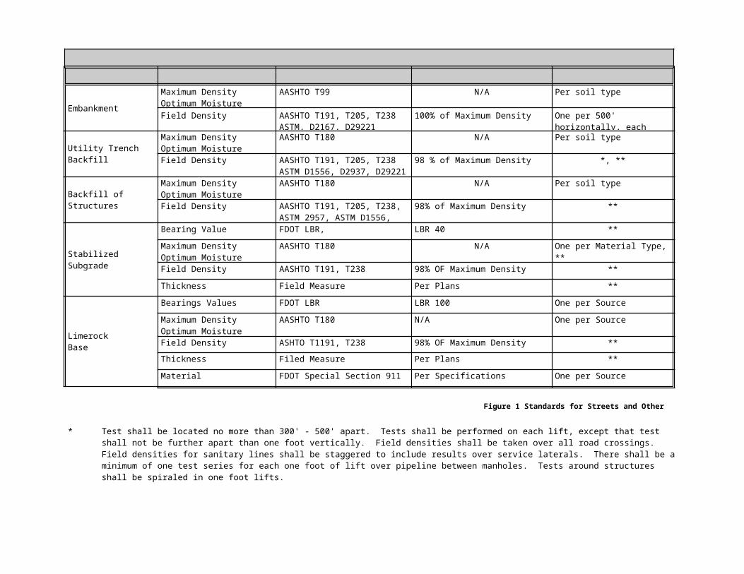
9. The following test schedule shall apply to all construction within the City of Plant City:
Embankment
Maximum DensityOptimum Moisture
AASHTO T99 N/A Per soil type
Field Density AASHTO T191, T205, T238ASTM, D2167, D29221
100% of Maximum Density One per 500' horizontally, each lift (1 ft.)
Utility Trench Backfill
Maximum DensityOptimum Moisture
AASHTO T180 N/A Per soil type
Field Density AASHTO T191, T205, T238ASTM D1556, D2937, D29221
98 % of Maximum Density *, **
Backfill of Structures
Maximum DensityOptimum Moisture
AASHTO T180 N/A Per soil type
Field Density AASHTO T191, T205, T238, ASTM 2957, ASTM D1556, D2167, D29221
98% of Maximum Density **
Stabilized Subgrade
Bearing Value FDOT LBR, LBR 40 **
Maximum DensityOptimum Moisture
AASHTO T180 N/A One per Material Type, **
Field Density AASHTO T191, T238 98% OF Maximum Density **
Thickness Field Measure Per Plans **
LimerockBase
Bearings Values FDOT LBR LBR 100 One per Source
Maximum DensityOptimum Moisture
AASHTO T180 N/A One per Source
Field Density ASHTO T1191, T238 98% OF Maximum Density **
Thickness Filed Measure Per Plans **
Material FDOT Special Section 911 Per Specifications One per Source
** Test shall be located no more than 300' - 500' apart. Tests shall be performed on each lift, except that test shall not be further apart than one foot vertically. Field densities shall be taken over all road crossings. Field densities for sanitary lines shall be staggered to include results over service laterals. There shall be a minimum of one test series for each one foot of lift over pipeline between manholes. Tests around structures shall be spiraled in one foot lifts.
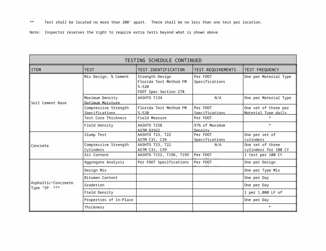
** Test shall be located no more than 200' apart. There shall be no less than one test per location.
Note: Inspector reserves the right to require extra tests beyond what is shown above
Figure 1 Standards for Streets and Other Related Facilities
TESTING SCHEDULE CONTINUED
ITEM TEST TEST IDENTIFICATION TEST REQUIREMENTS TEST FREQUENCY
Soil Cement Base
Mix Design, % Cement Strength DesignFlorida Test Method FM 5-520FDOT Spec Section 270
Per FDOT Specifications One per Material Type
Maximum DensityOptimum Moisture
AASHTO T134 N/A One per Material Type
Compressive StrengthSpecifications
Florida Test Method FM 5-520 Per FDOT Specifications300 PSI
One set of three perMaterial Type daily
Test Core Thickness Field Measure Per FDOT Specifications *
Field Density AASHTO T238ASTM D2922
97% of Maximum Density *
Concrete
Slump Test AASHTO T23, T22ASTM C31, C39
Per FDOT Specificationsfor type of concrete
One per set of cylinders
Compressive StrengthCylinders
AASHTO T23, T22ASTM C31, C39
N/A One set of three cylinders for 100 CY or fraction thereof
Air Content AASHTO T152, T196, T199 Per FDOT Specification 1 test per 100 CY
Asphaltic ConcreeteType “SP” ***
Aggregate Analysis Per FDOT Specifications Per FDOT Specifications One per Design
Design Mix One per Type Mix
Bitumen Content One per Day
Gradetion Stability/Flow One per Day
Field Density 1 per 1,000 LF of paving width
Properties of In-Place Material One per Day
Thickness *
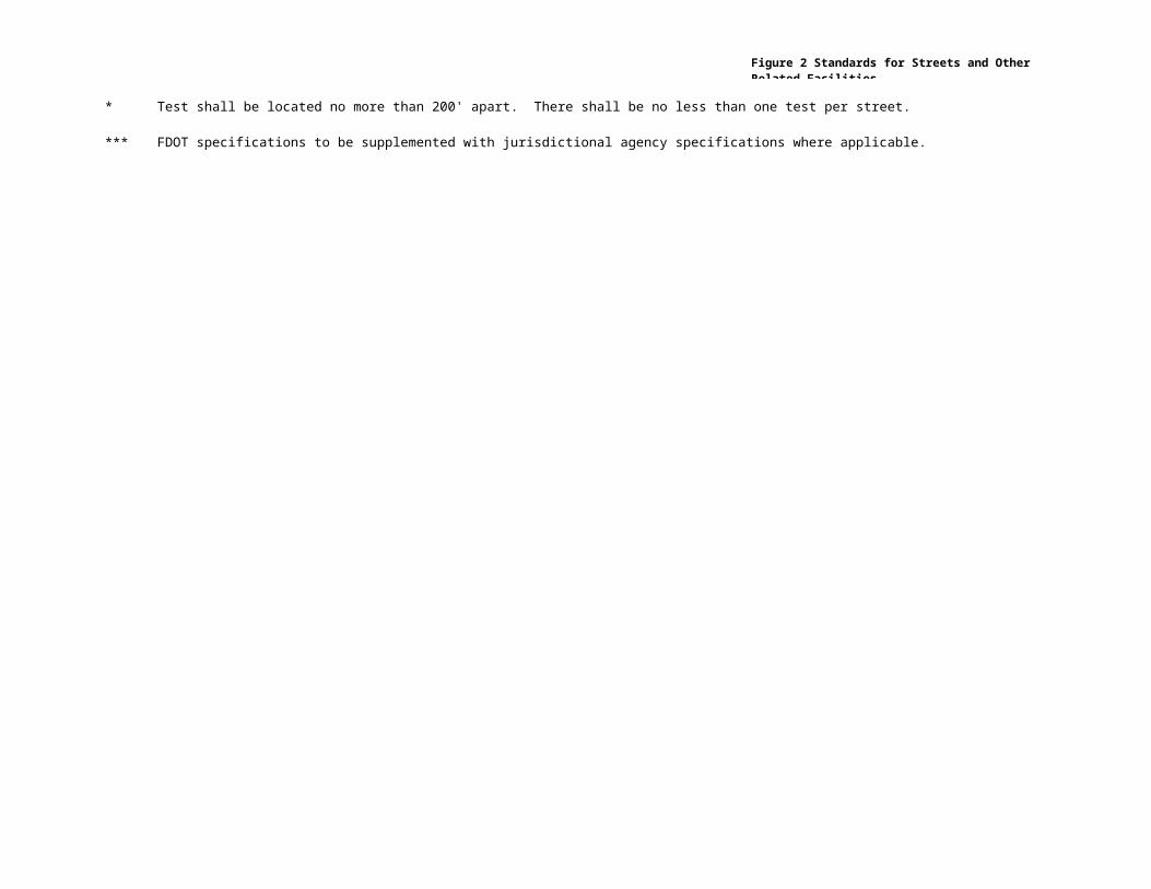
** Test shall be located no more than 200' apart. There shall be no less than one test per street.
*** FDOT specifications to be supplemented with jurisdictional agency specifications where applicable.
Figure 2 Standards for Streets and Other Related Facilities
Chapter 4
A) Plats
Prior to approval of the final plat, the applicant will have received final construction plan approval and have submitted an approved bond for the development. The purpose of the review and approval of the construction plans prior to final plat approval is to satisfy the design and specification requirements for construction.
The owner of property to be platted must provide an easement or dedication of all property needed for the construction of streets, thoroughfares, alleys, sidewalks, storm drainage facilities, floodways, water lines, wastewater lines and other utilities, and any other property necessary to serve the plat and to implement the requirements of this manual. Dedications shown on plats are irrevocable offers to dedicate the property shown. Once the dedication is made it may be accepted by an action by the City Commission.
No improvements shall be accepted until they are constructed according to the approved plans, details, and specifications, and record in the office of the county clerk.
Streets and the percentage of right of way to be dedicated required for streets is as follows:
1. When the full right of way width of a street is contained within the boundaries of the proposed plat, the entire required right of way contained within the boundaries of the plat must be dedicated for public subdivisions.
2. When a thoroughfare is along the perimeter of a proposed plat, sufficient right of way must be dedicated to provide one half of the thoroughfare plan requirement, measured from the centerline of the existing right of way or, if there is no existing right of way, the proposed right of way as determined by the City Engineer. If the property on the side of the thoroughfare opposite the property to be platted is railroad right of way or a utility or floodway easement, or if some physical or topographical condition makes the property on that side of the street undesirable for street right of way, the City Engineer may require additional right of way.
3. If a substandard right of way exists along the perimeter of a proposed plat and the plat includes property on both sides of the right of way the applicant will be required to provide sufficient right of way to meet the proposed intended use.
Corner clips or sight easements may be required as determined by the City Engineer.
All floodways shall be dedicated to the City.
The following dedication language is typical for subdivisions where all streets are to be maintained by the City.
1. Subdivision plats by no means represent a determination whether properties will or will not flood. Land within the boundaries of this plat may or may not be subject to flooding. The City of Plant City Engineering Department may have further information regarding flooding and restrictions on development.
2. This plat as recorded in its graphic form, is the official depiction of the subdivided lands described herein and will in no circumstances be supplanted in authority by any other graphic or digital form of the plat. There may be additional restrictions that are not recorded on this plat that may be found in the public records of Hillsborough County.
3. Drainage easements shall not contain permanent improvements, including but not limited to sidewalks, driveways, impervious surfaces, patios, decks, pools, air conditioners, structures, utility sheds, poles, fences, sprinkler systems, trees, shrubs, hedges, and landsc |andscaping paing plants other than grass, except for landscaping of stormwater detention and retention ponds as required by the City.
4. Side lot drainage easements shall be maintained by the individual lot owners.
5. Rear lot drainage easements (retention and detention ponds) shall be maintained by the homeowners association.
6. Rear lot drainage easements (swales) shall be maintained by the individual lot owners.
B) Plats Containing Private Roads
1. The private roads shown as tracts XXX are not dedicated to the public, but are hereby reserved by the owner for conveyance to a Homeowner’s Association, Community Development District, or other custodial and maintenance entity subsequent to the recording of this plat, for the benefit of the lot owners within the subdivision, as access for ingress and egress of lot owners and their future, of xxxxx subdivision.
2. Owner hereby dedicates to the City of Plant City and all providers of emergency, fire emergency, emergency medical, mail, package delivery, solid waste, sanitation, water, and reclaim utilities, and other similar governmental and quasi-governmental services, an non-exclusive access easement over and across the private roads and rights of way within tract xxx as shown herein for ingress and egress for the performance of their official duties.
C) Bonds, Security and Letters of Credit
1. Subdivision Construction
a. A bond or letter of credit in the amount of 110% of the total project cost will be required prior to the issuance of a final plat. While a bond is acceptable, the preferred security instrument is a letter of credit. The City Engineer shall review the bond/letter of credit and determine if the proposed amount reflects the actual construction costs in the event of default by the developer. All bonds/letters of credit should be submitted by the developer of the proposed subdivision. Other persons providing the security, such as contractors, may be accepted on a case by case basis. The term of the bond shall be the proposed construction time but generally should not exceed 1 year.

b. Private developments shall bond all utilities dedicated to the City, in addition all stormwater improvements, roadways and all ancillary and other items as deemed necessary by the City Engineer.
2. Term
a. The bond must cover the length of time during construction. This construction time is to be evaluated by the City Engineer as proposed by the Engineer of Record. Construction time generally should not exceed 1 year. On phased development, the developer may elect to submit one bond/letter of credit for all phases to be constructed. However, the City prefers that each phase meet separate bond/letter of credit requirements.
b The term of a subdivision warranty bond/letter of credit shall be 13 months from the date of acceptance by the City. The amount of the warranty bond shall be a minimum of 10% of the original construction bond/letter amount. The developer may request the reduced amount upon acceptance of the subdivision by the City. This provides the City with a 13 month warranty period for evaluation/repair of the improvements
D) Right of Way Security
1. Construction within the City right of way will require the submission of security to the City to secure restoration of the proposed work. While the security is primarily to secure the restoration of the right of way. The City may elect that the contractor provide security for the construction. The City will require that the security instrument be for a term to complete all work. No warranty period is required.
E) Other Security
1. The City may require other security as it deems necessary to secure construction and/or restoration. All security vehicles i.e. bonds, letters of credit, certificate of deposit, checks, etc., shall be evaluated by the City Engineer and City Attorney as to appropriateness. The City may reject any security vehicle that it feels does not reasonably provide the security necessary to meet the goal of the vehicle.
F) Work within FDOT right of way
1. The City may require at its discretion a bond or letter of credit for any work done on a Florida Department of Transportation right of way where the City is the applicant. The term and amount of the bond or letter of credit shall be at the discretion of the City Engineer but, shall not be less than 6 months and $25,000.
2. Any failure shall be repaired by the developer at the direction of the City Engineer within five working days unless the urgency of the problem requires an immediate response. In such case the City may take any corrective actions necessary and shall be reimbursed by the developer for all expenses.
G__CSX
1. Applicants requiring use of CSX rights of way in which the City is required to be the applicant shall reimburse the City for all security, licensing, insurance, bonds and all costs associated with acquiring and maintaining the permit.
H) Default
1. Upon default by the developer to take corrective the City Commission, City Engineer or other applicable public body may exercise it rights under the security upon (10) ten days written notice by certified mail to the parties to the instrument.

Chapter 5
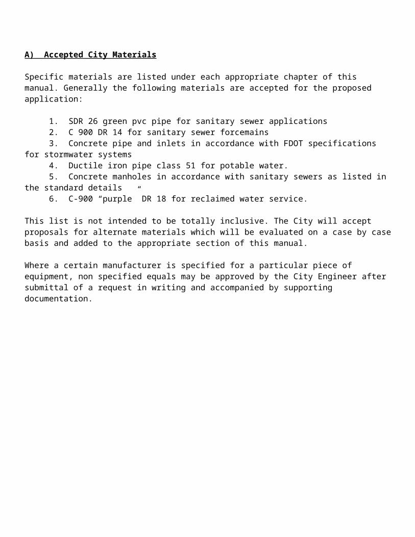
A) Accepted City Materials
Specific materials are listed under each appropriate chapter of this manual. Generally the following materials are accepted for the proposed application:
1. SDR 26 green pvc pipe for sanitary sewer applications2. C 900 DR 14 for sanitary sewer forcemains3. Concrete pipe and inlets in accordance with FDOT specifications for stormwater systems4. Ductile iron pipe class 51 for potable water.5. Concrete manholes in accordance with sanitary sewers as listed in the standard details6. C-900 “purple” DR 18 for reclaimed water service.
This list is not intended to be totally inclusive. The City will accept proposals for alternate materials which will be evaluated on a case by case basis and added to the appropriate section of this manual.
Where a certain manufacturer is specified for a particular piece of equipment, non specified equals may be approved by the City Engineer after submittal of a request in writing and accompanied by supporting documentation.
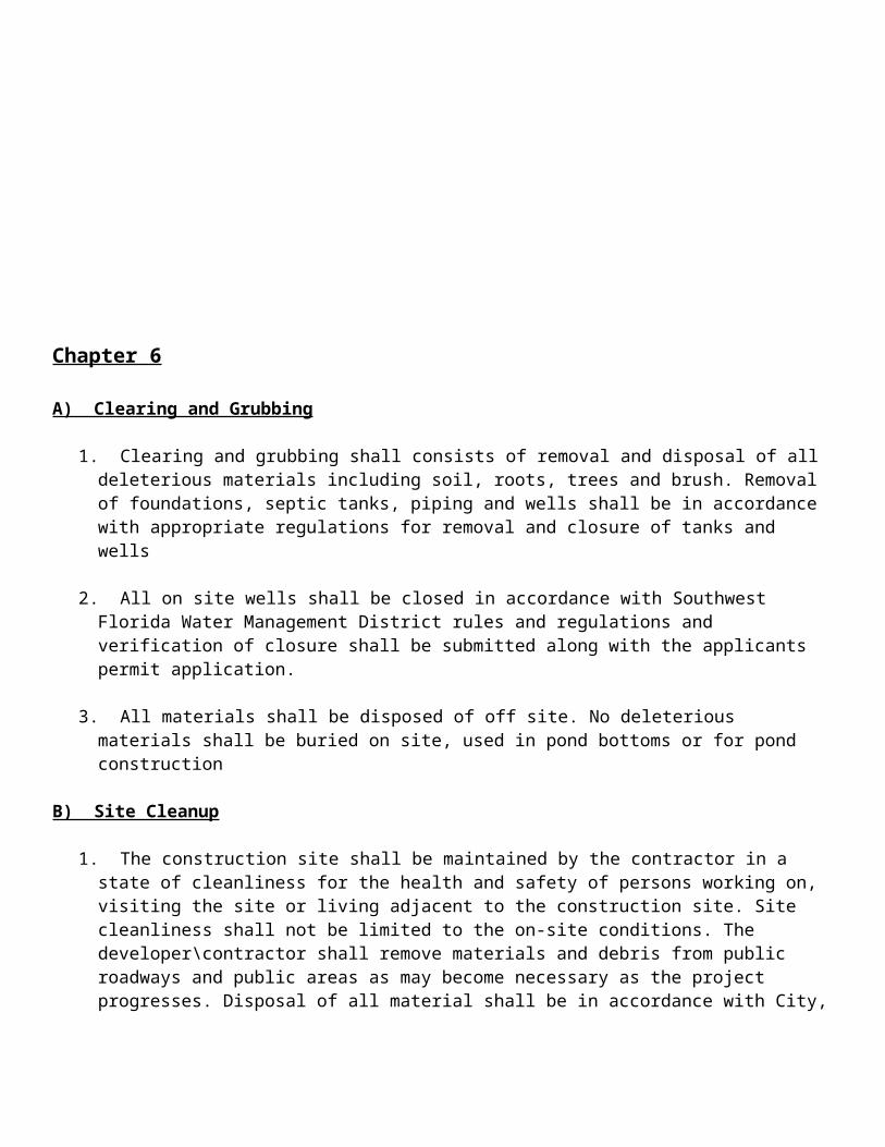
Chapter 6
A) Clearing and Grubbing
1. Clearing and grubbing shall consists of removal and disposal of all deleterious materials including soil, roots, trees and brush. Removal of foundations, septic tanks, piping and wells shall be in accordance with appropriate regulations for removal and closure of tanks and wells
2. All on site wells shall be closed in accordance with Southwest Florida Water Management District rules and regulations and verification of closure shall be submitted along with the applicants permit application.
3. All materials shall be disposed of off site. No deleterious materials shall be buried on site, used in pond bottoms or for pond construction
B) Site Cleanup
1. The construction site shall be maintained by the contractor in a state of cleanliness for the health and safety of persons working on, visiting the site or living adjacent to the construction site. Site cleanliness shall not be limited to the on-site conditions. The developer\contractor shall remove materials and debris from public roadways and public areas as may become necessary as the project progresses. Disposal of all material shall be in accordance with City, State and Federal regulations.
2. All portions of the project open to the public shall be fenced, barricaded and otherwise protected from all construction activities through whatever means acceptable to the City.
C) Erosion Control
1. An erosion control plan with details must be submitted prior to any activity on site and be incorporated into the final design plans. The plan must show considerations for all types of erosion including water borne and air borne particles that shall be retained on site. In all cases the Developer shall be ultimately responsible for the success of the erosion control plan and shall provide or direct his contractor to provide sufficient controls to protect the general public and their properties from the hazards of erosion including installation of track pads for vehicles exiting the site onto public roadways. Materials which have migrated off site shall be removed immediately by an approved method and spoils disposed of in accordance with all State, local, and Federal rules and regulations.
2. Seeding, mulching, sodding and/or other acceptable methods shall be used to prevent erosion during all construction activities. The developer shall be required to maintain curbs and gutters free of accumulations of sand and earth. Temporary silt basins may be required during construction. Maintenance of the basins shall be provided by the developer until final inspection is complete.
3. In all instances no excavated material shall be stockpiled in such a manner as to direct stormwater runoff directly off the project site or into any adjacent water body or stormwater collection facility. Inlets and catch basins shall be protected from sediment laden storm runoff until the completion of all construction
operations that may contribute sediment to the inlet.
4. The City may require that the stormwater conveyance system be cleaned and televised prior to acceptance by the City.
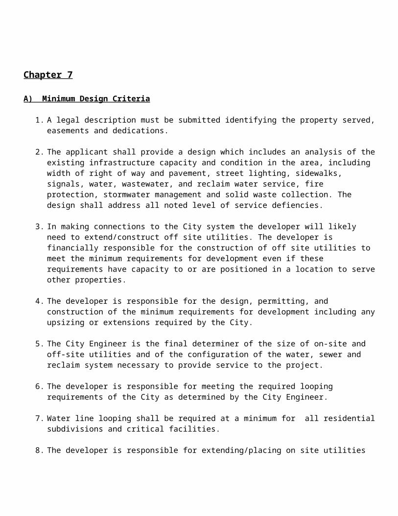
Chapter 7
A) Minimum Design Criteria
1. A legal description must be submitted identifying the property served, easements and dedications.
2. The applicant shall provide a design which includes an analysis of the existing infrastructure capacity and condition in the area, including width of right of way and pavement, street lighting, sidewalks, signals, water, wastewater, and reclaim water service, fire protection, stormwater management and solid waste collection. The design shall address all noted level of service defiencies.
3. In making connections to the City system the developer will likely need to extend/construct off site utilities. The developer is financially responsible for the construction of off site utilities to meet the minimum requirements for development even if these requirements have capacity to or are positioned in a location to serve other properties.
4. The developer is responsible for the design, permitting, and construction of the minimum requirements for development including any upsizing or extensions required by the City.
5. The City Engineer is the final determiner of the size of on-site and off-site utilities and of the configuration of the water, sewer and reclaim system necessary to provide service to the project.
6. The developer is responsible for meeting the required looping requirements of the City as determined by the City Engineer.
7. Water line looping shall be required at a minimum for all residential subdivisions and critical facilities.
8. The developer is responsible for extending/placing on site utilities in a manner as requested by the City Engineer to position the City to provide service to other properties. The City Engineer is the final determiner of the location and configuration of on-site and off-site piping in a manner that best serves the City.
9. Determination of whether or not on-site utilities will be public or private will be determined by the City Engineer, however private water systems are allowed only when all parts of the project property will be forever served by one water meter and possibly one irrigation meter.
10. The City will not serve multiple customers through private, shared or third-party facilities. Each customer must own, have control of and be responsible for the facilities between the City’s point of service and the building or other usage location. This includes water service lines, sewer service connections and reclaim water service.
11. Each customer will be individually metered for potable water and will not share the privately owned utilitie downstream of the meter with any other customer or potential customer except as authorized by the City Engineer
12. If it is determined that either water, sewer or reclaim water service is to be remain private then all utilities within the project must be private.
13. An approved backflow device maintained by the property owner, is required between the City water system and the private water system.
14. Commercial projects may have private on site water service when sanitary and reclaim on site remain private. The developer may have a maximum of 6 (six) water meters at the right of way.
15. All water meters are required to be placed within the right of way.
16. Private fire hydrants shall be constructed in accordance with this manual and shall be annually certified by the City of Plant City Fire Department.
17. All streets either public or private shall be constructed in accordance with this manual.
18. Streets in subdivisions shall have the asphaltic concrete installed in two lifts in accordance with this manual.
19. Design of water and sewer systems shall be based upon 350 gpd per ERU average daily demand.
20. Easements shall meet the following criteria.
a. Watermains and sewer forcemains: 20 ft minimum width no less than 7.5’ on each side of main. The minimum width may be reduced to 10’ if easement is parallel and contiguous to a public right of way. Easement must extend 7.5 ft from the terminus of the main.
b. Sewer gravity mains: 25 ft minimum width with no less than 12.5 ft on each side of main. The minimum width may be reduced to 10’ if easement is parallel and contiguous to a public right of way. Easement must extend 12.5 ft from the terminus of the main.
c. Watermain and sewer gravity main in same easement: 30 ft minimum width based upon 7.5 ft for the watermain, 12.5 ft for the gravity sewer and 10.0 seperation between the two mains. Minimum width may be reduced by 10 ft if the easement is parallel to and contiguous to a public right of way. The easement must extend the greater of 12.5 ft beyond the terminus of the sewer gravity main or 7.5 ft beyond the terminus of the watermain.
d. Hydrant 7.5 ft each side of hydrant
e. Lift stations, and pump stations shall have a minimum 50’ x 50’ easement with paved access to right of way. The easement maybe reduced at the discretion of the City Engineer.
f. Example easement language is included in Appendix XXXXXXXXXXXXX
B) Private Developments
1. Private streets shall conform to the same standards regulating the design and construction of public streets and maybe allowed under the following conditions:
a. Streets shall be designed to meet City requirementsb. Private streets shall be accessible at all times for emergency and public service vehicle use.c. The Fire Chief shall approve all private streets within the City.d. Construction and inspection standards for public road shall apply for private roads unless otherwise noted within these guidelines.e. Covenants have been approved by the City and recorded which provide for maintenance of the
private streets and associated parking areas by the owner, private road maintenance agreement, or homeowners association or other legal entity.
f. Private roads shall not result in landlocking of present or future parcels, conflict with any transportation or street improvement plan, nor obstruct public street circulation.
g. Final site plans that depict private streets will include an unconditional and irrevocable offer of dedication that may be accepted by the City Commission at such time as the street is needed for development of contiguous property or for the protection of public health, safety and welfare.
h. Private streets shall be permanently established by commonly owned tract or easement.i. Private roads shall be clearly described on the face of the plat.j. The developer of private streets shall have a written agreement pursuant to section 316.006(2)(b),
Florida Statutes providing for among other things, the reimbursement of the actual costs of traffic control and enforcement and for liability insurance and indemnification by the party or parties that own or control the private streets.
k. Alleys shall meet the criteria for private streets in addition to the criteria below.l. Alleys shall have a maximum alley tract or easement width of 20 feet with a pavement surface of 16
feet.m. Alleys are only allowed when lots served have full frontage on a public street and provide direct
pedestrian and emergency vehicle access to the public street.n. Alley entry shall be provided by a driveway approach.o. Acceptance as public streets. The City will consider acceptance of private streets as public streets
only if the street(s) meet all applicable public street standards, including right of way width.
2. Gates & Fences
a. Gates and fences shall not interfere with the clear site distance of intersections and driveways. Driveway gates shall be positioned to provide 20’ behind the right of way line. All fences along City right of way shall be approved by the City Engineer.
3. Gate Installations
a. Gates, if provided across private roads, shall be designed, placed, installed, and accessory features( such as key boxes, “break away” devices, automatic openers, etc.) provided to the satisfaction of the City Engineer and in accordance with provisions outlined by the Fire Chief.
b. If a private road is to be gated in close proximity to a public road then a thirty foot minimum radius
turnaround shall be provided at the gated entrance. A minimum storage space shall also be provided to accommodate two vehicles.
c. Gate design may incorporate one or two gate sections to meet the required minimum gate width of twenty-four feet. If the entrance will incorporate a median, guard shack or similar structure that necessitates a divided gate arrangement, the gate widths may be reduced in approved by the City Engineer, but in no case shall any single gate or street pavement have a clear opening of less than 20 feet.
d. If a gate design incorporates any overhead obstruction, said obstruction must be a minimum of 14 feet above the finished road surface.
e. Approach and departure areas on both sides of a gated entrance must provide adequate setbacks and proper alignment to allow free and unimpeded passage of emergency vehicles through the entrance area. All entry gates must be setback a minimum of 100 feet from any adjacent public street right of way to allow for vehicle stacking out of the public travel lanes. Any exception must be approved by the City Engineer.
f. All components of the gate system must be maintained in an approved operating condition, with all components serviced and maintained on a regular basis as needed to insure proper gate operation. A proper power supply shall be maintained to all electrical and electronic components at all times.
g. Each security gate regulated under this section shall be subject to a performance test as determined by the Fire Chief, Director of Public Works or the City Engineer. Upon failure of a performance test, the security gate system shall be disabled and maintained in the open position until repaired, and shall not be placed back in service until tested and authorized by the Fire Chief, Director of Public Works or the City Engineer.
h. All streets, gates, fire protection features, signage, stormwater control devices and conveyances are subject to periodic inspection by the City and must be repaired immediately if found to be in a condition of disrepair. The City shall have the right to enter the subdivision and disable, open or remove any gate, device, or other feature that may impede or controls vehicle access at the sole expense of the Propertyowners Association. Emergency repairs shall be assessed against the Propertyowners Association.
i. The person or corporation in control of the property is responsible for, and liable for any violations of this section. This includes, but is not limited to, the developer, property owner, the Propertyowners Association and its officers, if applicable, or other who may own or exercise control over the property.
j. All components of the gate system must be maintained in an approved operating condition, with all components serviced and maintained on a regular basis as needed to insure proper gate operation. A proper power supply shall be maintained to all electrical and electronic components at all times.
k. Each security gate regulated under this section shall be subject to a performance test as determined by the Fire Chief, Director of Public Works or the City Engineer. Upon failure of a performance test, the security gate system shall be disabled and maintained in the open position until repaired, and shall not be placed back in service until tested and authorized by the Fire Chief, Director of Public Works or the City Engineer.
l. All streets, gates, fire protection features, signage, stormwater control devices and conveyances are subject to periodic inspection by the City and must be repaired immediately if found to be in a condition of disrepair. The City shall have the right to enter the subdivision and disable, open or remove any gate, device, or other feature that may impede or controls vehicle access at the sole expense of the Homeowners Association. Emergency repairs shall be assessed against the
Homeowners Association.
4. Property Associations Required
a. Property developed with private street and alleys must have a mandatory property owners association which includes all property served by private streets. The association shall own and be responsible for the maintenance of private streets, parks and other Property Association appurtenances. The association shall own and be responsible for the maintenance of streets, lights and other improvements. The association documents shall be reviewed by the City Attorney and subject to approval by the City to insure that they conform to this and other applicable City ordinances and concerns. The documents shall be filed of record prior to the approval of the final plat. Lot deeds may not be dissolved without the prior written consent of the City. No portion of the association documents pertaining to the maintenance of the private streets and alleys and assessments therefore maybe amended with the written consent of the City.
b. Private Street Lot- Private streets and alleys must be constructed within a separate lot owned by the property owners association. This lot must conform to the City’s standards for public street and alley right of way. An easement covering the street lot shall be granted to the City providing unrestricted use of the property for utilities and storm drainage systems and the maintenance of same. This right shall extend to all utility providers including telephone and cable companies, operating within the City. The easement shall also provide the City with the right of access for any purpose related to the exercise of a governmental service or function, including but not limited to fire and police protection, inspection and code enforcement. The easement shall permit the City to remove any vehicle or obstacle within the street lot that impairs emergency access. Variation to streets and right of way widths must be approved by the City Engineering Department.
c. Construction and Maintenance Cost- The City shall not pay for any portion of the cost construction or maintaining a private street. The Propertyowners Association shall maintain an escrow account as approved by the City for all road maintenance.
d. City Utilities- Water, sewer and drainage facilities placed within private street and alley lot shall be installed to City standards and dedicated to the City or Homeowners Association as part of the approval of the final plat and shall be clearly indicated so on the plat. All City regulations relating to the infrastructure, financing, developer cost participation and capital cost recovery shall apply to developments with private streets with the exception of those applying to internal street construction. Street lights and signs shall be installed and maintained by the homeowners association subject to the approval of the City. The property association documents shall give the City the right, after giving written notice to perform maintenance upon streets and alleys to protect health, safety and welfare of the residents and to place a lien upon the lots within the association to recover the cost of such maintenance.
2. Private Developments Submittals & Reviews
b. Plans and Inspections- Developments proposed with private streets must submit to the City the same plans and engineering information required to construct public streets and utilities. Requirements pertaining to inspection and approval of improvements prior to issuance of building permits shall apply. Inspection and review fees charged for these services shall also apply. The City may periodically inspect private streets and require repairs necessary to insure emergency access.
c. Waiver of Services-The subdivision final plat, property deeds and property owners association documents shall note that certain City services shall not be provided on private streets. Among the services which will not be provided are: routine police patrols, street lighting, enforcement of traffic and parking ordinances and preparation of accident reports. All private traffic regulatory signs shall conform to the State of Florida Manual of Uniform Traffic Control Devices. Depending on the character of the proposed development other services may not be provided.
d. Trash Pickup and Disposal-Private streets serving condominium, townhomes or apartments shall not be eligible for curbside pickup of trash and debris. Centralized trash pickup meeting City standards will be required.
e. Petition to Convert to Public Streets- The property association documents shall allow the association to request the City accept private streets and alleys and the associated property as public streets and right of way upon written notice to all association members and the favorable vote of 75% of the membership. However, in no event shall the City be obligated to accept said streets and alleys as public. Should the City elect to accept the streets and alleys as public, the City may inspect the private streets and assess the lot owners for the expense of needed repairs concurrent with the City’s acceptance of the street and alleys. The City shall be the sole judge of whether repairs are needed. The City may also require, at the association’s expense, the removal of guard houses, access control devices, landscaping or other aesthetic amenities located within the street lot. The association document shall provide for the City’s right to such assessment. Those portions of the association documents pertaining to the subject matter contained in this paragraph shall not be amended without the written consent of the City.
f. The property association documents shall pay the monthly costs for street lighting and police. Language shall be provided in the association documents providing for the collection and payment of these costs.
g. Property association documents shall provide for the maintenance of streets and related facilities.h. Hold Harmless- On the subdivision final plat shall be language whereby the property owners
association, as owner of the private streets and appurtenances, agrees to release, indemnify, defend and hold harmless the City, any governmental entity and public utility for damages to the private street occasioned by the reasonable use of the private street by the City, governmental entity or public utility, for damages and injury (including death) arising from the condition of said private street; for damages and injury (including death) arising out of the use by the City, governmental entity or public utility of any restricted access gate or entrance; and for damages and injury (including death) arising out an of any use of the subdivision by the City, governmental entity or public entity. Further, such language shall provide that all the owners of all lots shall release the City, governmental entities and public utilities for such damages and injuries. The indemnification contained in this paragraph apply regardless of whether or not such damages and injury (including death) are caused by the negligent act or omission of the City, governmental entity or public entity, or their representative officers, employees or agents.
i. Sidewalks and Bikeways- Sidewalks shall be constructed in accordance with this manual for all lots adjoining dedicated streets, along major through fares where lots do not adjoin the street or in other areas as required by the City Engineer. Sidewalk construction maybe delayed until development of lots, but in locations not adjacent to lots and across bridges and culverts, the sidewalk shall be constructed with the other improvements to the subdivision or addition. Exceptions may be approved by the City Engineer. The City may require, in order to facilitate pedestrian access from the development to schools, parks, playgrounds or other nearby streets, or in support or accordance with
an approved bicycle and pedestrian masterplan, perpetual unobstructed easements a minimum of 15 feet in width. Easements shall be indicated on the plat. Bikeways maybe required in accordance with a bikeway masterplan or as indicated in this document. Such bikeways shall be constructed at the time of site development.
j. Drainage and Storm sewer- Design of stormwater management systems shall be in accordance with this document.
j. Secondary Access- All gated subdivisions shall provide a secondary access point accessible by emergency vehicles. This requirement may be waived if the applicant installs a boulevard section as indicated in this manual.
k. Federal Requirements- The Post Office requires 7 day access for mail delivery. If a security gate or fencing is used, a key keeper box with retractable key reel that will accommodate a post office arrow lock and/or device needed to gain access into the development, must be installed next to the door or gate that the carrier uses to enter the complex. ( Systems that use a key board to punch in codes, in most cases will accept a post office arrow lock in the control panel) Note: Carriers must not carry keys, written codes, electronic openers or badges for entrance into the development or buildings. Deviations from this requirement may only be authorized when accompanied by a letter of authorization from the local postmaster.
l. Electrical Services: All electrical services shall be placed underground within a utility easement acceptable to the Tampa Electric Company (TECO). The developer shall be responsible for securing all necessary approvals from TECO for electric service.
C) Propertyowners Associations (Public streets)
1. A propertyowners association is required for all new residential subdivisions, condos (commericial or residential), townhomes or subdivided parent parcels for commercial or industrial use within the City of Plant City.
2. The propertyowners association shall be responsible for the maintenance and operation of the stormwater management system from the edge of the right of way line.
3. Property requiring a backflow prevention device shall provide an annual certification of inspection for the backflow control.
Chapter 8
Transportation Section
A) Forward
1. Any development that is required to construct, repair, widen, or in any way improve a public or private street, right of way, alley, or easement shall comply with the minimum standards of this section and shall be designed by a professional engineer licensed in the State of Florida.
2. The design of the transportation system shall be designed to incorporate traffic calming techniques and promote safe pedestrian and bicycle safety.
3. This section supplements additional standards found in the following technical documents that are incorporated by reference.:
a. Florida DOT - Manual of Uniform Minimum Standards for Design, Construction and Maintenance for Streets and Highways, latest edition (Florida Green Book).
b. Florida DOT - Procedures Manual for Flexible Pavement Design, latest edition.
c. U.S. Department of Transportation, Federal Highway Administration - Manual on Uniform Traffic Control Devices for Streets and Highway, latest edition.
d. Florida DOT - Standard Specifications for Road and Bridge Construction, latest edition.
e. AASHTO - Standard Geometric Design for Highways and Streets, latest edition.
f. Florida DOT - Roadway and Traffic Design Standards, latest edition.
B) Design Speed
1. Speed zones within the City shall comply with Section 316.189 F.S. The maximum speed for local residential streets shall be 30 mph. Requests for modifications to the design speed shall require a detailed analysis of the roadway segment and approval by the City Commission.
C) Required Sight Distance
2. The required sight distance shall be determined by FDOT standard index 546 but in no case shall be less than 290 feet from the stopping vehicle taken at the stop bar. No obstructions shall be present within the sight window from 2 feet above the pavement to 8 feet 6 inches. No trees or vegetation shall be planted within the right of way that do not meet the requirements of FDOT standard index 546.
D) TRANSPORTATION ANALYSIS
1. The City Engineer may require a transportation analysis when in the City Engineer’s opinion the proposed development will significantly impact the transportation network.
a. A transportation analysis is prepared by a professional traffic engineer. The Institute of Traffic Engineers (ITE) trip generation rates or another approved source is to be used as the basis for trip generation calculations. In addition the detailed traffic analysis shall include, but not be limited to, the following:
1. Level of Service calculations at each project access point for both the A.M. and P.M. peak hours.
2. A determination of need for auxiliary lanes.
3. A determination of need for traffic signalization or other control devices.
4. Other transportation factors as may be appropriate as determined by the City of Plant City, based upon generally accepted traffic engineering practices.
E) Defintions and Calculations
Urban: Roadway meeting the general criteria of an urban roadway includes curb and gutter.
Rural: Roadway without curb and gutter usually has roadside ditches to route roadway runoff.
Average Annual Daily Traffic (AADT): The total volume passing a point or segment of a road facility, in both directions, during a 24-hour period. It is commonly obtained during a given time period, in whole days greater than one day and less than one year, divided by the number of days in that time period. The volume is then adjusted for seasonal variations using the Seasonal Adjustment Factor.
Estimated K Factor (Peak-to-Daily): The ratio of peak hour traffic to daily traffic. The K Factor allows the conversion from a peak hour volume to a daily volume and the reverse. Table 1 presents an example calculation of the K Factor (as presented in the FDOT 1995 LOS Manual).
Table 1 – Estimating the K Factor Measured Day
PeakHour
Daily Volume
Peak HourVolume
Peak to DailyRatio
1/20/98 4-5 PM 21,000 1.700 0.0811/21/98 5-6 PM 22,000 1,800 0.0821/22/98 5-6 PM 22,000 1,900 0.086Average N/A 21,667 N/A 0.083
1997 Seasonal Factor* = 1.12Estimated K Factor = 0.083 X 1.12 = 0.093
* 1998 Seasonal Factors were used due to the absence of published 1999 Seasonal Factors
Directional Distribution Factor (D Factor): This factor accounts for the directional distribution of traffic. It is used to convert peak hour traffic to directional peak hour traffic. Table 2 illustrates how the D Factor is calculated:
Table 2 – Calculating D FactorMeasured
DayPeak Hour
Peak HourVolume
PredominateDirectional Peak
Volume
Opposite Direction
Peak Volume
DFactor
1/18 4-5 PM 1,600 960 640 0.6001/19 5-6 PM 1,900 1,026 874 0.5401/20 4-5 PM 2,000 1,130 870 0.565Sum 5,500 3,116 2,384 1.703
Average 1,833 1,039 795 0.568Estimated D Factor = 0.568
Directional PM Peak: The traffic volume for the peak hour in the predominant direction of flow, in vehicles per hour: PM DIR PEAK = (AADT) (K Factor) (D Factor)
K or Design Hour Factor: The ratio of design hour traffic to average annual daily traffic. The K-100 factor allows the conversion from a peak hour volume to a daily volume. Within urbanized areas the K-factor for the 100th hour is generally around 0.09. Table 2 is an example of a K-100 calculation:
CALCULATING K
MeasuredDay
Peak Hour
Peak Hour Volume
DailyVolume
Peak to Daily Ratio
1/18 4-5 PM 1600 20000 .0801/19 5-6 PM 1900 25000 .0761/20 5-6 PM 2000 22000 .091
Average 22333 .082PEAK DAILY VOLUME/AVERAGE DAILY VOLUME = 25000/22333 = 1.119ESTIMATED K FACTOR = .082 X 1.119 = .092
P.M. Peak Directional Peak: The traffic volume for the peak hour in the predominant direction of flow, in vehicles per hour. PM DIR PEAK = (ADT) (K-100) (D-FACTOR)
ESTIMATED D FACTOR = 0.568

F) Minimum Roadway Right of Way and Sidewalk Width
Roadway Classification
MaximumAADT
Minimum Right of Way (ft)
Utility Easement (ft)(each side of
road)
Sidewalk Width (ft)
Sidewalk Clearzone (ft)
(each side)Local (urban) 1500 60 10 5 2.5Local (rural) 1500 80 10 5 2.5
Minor Collector (urban)
3000 60 10 5 2.5
Minor Collector (rural)
3000 100 10 5 2.5
Major Collector (urban)
12000 150 10 6 2.5
Major Collector(rural)
12000 200 10 6 2.5
Arterial (urban) >12000 200 15 8 2.5
G) Minimum Clear Recovery Zone
1. The minimum clear zone for all roadways with mountable curb or roadways without curbs and design speeds less than 45 mph shall be 18’. Calculation of the clear zone shall be made from the edge of the travel lane to the roadside edge of the sidewalk. Clearzone areas shall be transversable and recoverable as defined by the Florida Department of Transportation.
2. The minimum clear zone for local and collector roadways with Type F curb shall be 4’ from the face of curb for design speeds less than 45 mph.
3. F and D curb and gutter shall not be used on roadways with design speeds greater than 45 mph.
4. The City follows FDOT index 700 for the calculation of horizontal clearances.
H) Stopping Sight Distance
Stopping sight distance shall be in accordance with the following table:
Design Speed (mph)
10 15 20 25 30 35 40 45 50 55 60 65 70
Stopping Sight
Distance (ft)
Minimum
50 80 115 155 200 250 305 360 425 495 570 645 730
I) Pavement Widths
Pavement Widths shall be in accordance with the following table:
Roadway Type Pavement Width(per lane) (ft)
Turn Lanes (ft) Shoulder Width (ft)
Bike Lane (ft)
Local (urban) 11 11 Not Required Not RequiredLocal (rural) 11 11 6 Not RequiredCollector (urban) 12 12 6 5Collector (rural) 12 12 8 5Arterial (urban) 12 12 8 5
All bike lanes shall be marked in accordance with FDOT standardsShoulders shall be paved and constructed in accordance with the type of road construction.
J) Median Widths
Median widths shall be in accordance with the following table:
Design Speed Minimum WidthUrban Section 45 mph or less 16 ftUrban Section 50 mph or greater 19.5 ftRural Section 55 mph or less 22 ftRural Section 55 mph or greater 40 ft
K) Roadway Development Standards
1. New intersections along one side of an existing road shall coincide with the center lines of existing intersections. Where an offset is necessary at an intersection, the distance between center lines of the intersecting roads shall be no less than 150 feet except when divided by a raised median.
2. No two roads may intersect with a local road on the same side at a distance of less than 150 feet measured from centerline to centerline of the intersecting road. When the intersected road is a major or minor collector, the distance between intersecting roads shall be no less than 440 feet.
3. Access to subdivisions by fire apparatus shall not be less than 20 feet (6 meters) of unobstructed width, able to withstand live loads of fire apparatus, have a minimum vertical clearance of 14 feet and access slope not to exceed 5%.
L) Roads with No or Limited Outlet
1. A turnaround shall be located at the terminus of any road greater than 150 feet in length with no outlet.
2. Cul-de-sac turnarounds shall consist of a travel lane with a minimum outside turning radius of 50 feet.
3. All subdivision roads that cross railroad tracks or bridges shall provide a second outlet.
4. T type turnarounds may be utilized with the permission of the City Engineer if the roadway terminus is scheduled to be extended at a future date.
M) Continuation of Existing Streets
The continuation of existing street networks is desired to promote connectivity and multi-way access into developments. Existing streets shall be continued at the same width and may be reduced to a narrower standard if permitted in this manual and subject to provision of the appropriate transitions between roadway widths.
N) Street Intersections
Street intersections should be at right angles to maximize sight visibility. No street angle less than 60 degrees will be permitted unless required by extra ordinary conditions
0) Street Jogs
Street jogs with centerline offsets less than 125 feet shall not be permitted.
P) Specific Requirements
1. Clearing and Grubbing: All clearing and grubbing of the roadway and right of way shall be done in accordance with the Florida Department of Transportation Standard Specifications. All deleterious material shall be removed from the right of way and properly disposed.
2. Vertical Alignment : Street grades shall conform to the maximum extent possible to the natural topography. Maximum grades are as follows:
a. Arterial Street 3%b. Collector Street 4%c. Residential Streets 8%d. No streets shall be less than 0.36%
The Florida Department of Transportation Roadway Design Standards shall be used for the determination of the need for vertical curves for changes of grades based on roadway types.
3. Storm Drainage: All streets shall be designed to provide adequate stormwater systems. For multi phased projects a master stormwater design submittal and approval is required for all phases at the time of permitting for the first phase of development to assure compatibility between all phases.
a. The roadway level of service for flooding is as follows:
1. For the 25 year 24 hour storm, the hydraulic grade line of the stormwater system must be one foot below the roadway edge of pavement.2. There shall be no street flooding outside the curb and gutter area for the 25 year 24 hour storm.3. The roadway shall remain passable with a maximum of 3 inches of water depth in the travel lanes for the 100 year 24 hour storm.4. Roadway culverts shall be designed to 100 year 24 hour storm event.
4. Underdrain: Underdrain shall be used only where absolutely necessary. When underdrain is used, a water resistant base must also be used. The minimum separation between the bottom of the roadway base and the seasonal high water table is 1.0 feet for a water resistant base and 2 feet for limerock or similar material. If underdrain is used, the stormwater system shall include this base flow in the design of the piping, inlets and ponds. Clean outs shall be provided and marking wire used for future locates.
5. Street Curb and Gutter: Curb and gutter shall be installed on all arterial, collector and residential streets unless approved in writing by the City Engineer. The type of curb and gutter used shall be based on various factors including but not limited to: design speed, roadway cross section type, need to limit access to property, clear zone protection for sidewalks, trees or other appurtenances in the right of way. The City Engineer has the final determination of the appropriateness of the type of curb and gutter proposed for a specific project.
6. Curb Line Radius: The minimum curb line radius for residential streets is 25 feet, for commercial is 35 feet and for industrial areas is 40 feet.
7. Sidewalks: Sidewalks shall be constructed with 3000 psi at 28 days concrete with no wire mesh. Materials and Methods shall conform to the latest edition of Florida Department of Transportation Standard Specifications for Road and Bridge Construction. The minimum thickness shall be six inches and the minimum width is five feet. All sidewalks and handicap ramps shall be designed to meet the ADA requirements in affect at the time of construction.
8. Street Markers: The design plans shall include a proposed signing and marking plan. The plan shall contain the following minimum information:
a. Location and type of all stop bars, center line striping, edge striping, turn lane striping, arrows, school zone markings, bike lanes designations, gore area markings etc. As a general guideline, the City does not provide centerline striping on residential roads. Collector and higher classes of roadways are typically striped. All striping shall be thermoplastic and shall follow The Florida Department of Transportation Standard Specifications Section 711. Stop bars shall be placed a minimum 4’ from the edge of the stop bar to the crosswalk or intersection.
b. Stripping and signage of private amenity crossings such as bike lanes, golf cart, private pedestrian crossings or similar facilities shall be maintained by the entity owning the private facility.
c. Location and type of all street name signs, speed limit signs, advisory signs, school zone signs, stop signs, no trucks information signs and others shall be designated on the submitted plan. All signs
shall meet the Florida Department of Transportation (FDOT) and Manual of Uniform Traffic Control Devices (MUTCD) for size, materials, reflectivity and placement. A fee shall be paid by the developer to cover the City’s cost of the sign purchase/manufacture, materials and installation by City crews.
d. Private Signs: The City can permit the installation by right of way use permit of private or “upgraded” street name signage based on the following criteria:
1. Signs shall meet the FDOT and MUTCD standards for letter size including 9" blanks with 6" letters, reflectivity and placement.
2. The replacement fee shall still be paid to the City for the installation of standard signs unless financial and physical maintenance responsibility of signage is assigned to a Community Development District or a mandatory homeowner’s association with sufficient dues and resources to cover such expenses and recorded documents which clearly specify this maintenance duty.
3. In no case shall any regulatory signs be non FDOT or MUTCD standard. These signs must be maintained by the City.
4. Pavement Reflective Markers (RPM’s) - The appropriate color coded pavement reflective markers shall be installed at every fire hydrant for each direction of approach . In addition, RPM’s shall be used where deemed appropriate to designate a specific roadway hazard. If bike lanes are provided adjacent to the travel lanes, RPM’s shall be installed along with the proper edge stripping to clearly delineate the travel lane from the bike lane. RPM’s may also be used on residential streets in lieu of double yellow striping to mark the roadway centerline.
9. Traffic Signals:
Where traffic studies indicate the need for a traffic signal, the traffic signal design shall be in full conformance with the latest Florida Department of Transportation requirements for signal design. The signal controller and its programming shall be compatible with the City’s interconnected system. All new signals must connected to the City’s central control system via fiber optic cable. The City’s fiber cable is a special hybrid color code and both single mode and multimode fiber is required. The fiber shall be in accordance with the Florida Department of Transportation District VII Fiber Optic Traffic Specifications #684. All new signals shall be designed with LED in lieu of incandescent bulbs for brightness and longevity. All new signals shall include a battery back up.
10. Poles: The poles shall be mast arms shipped as plain galvanized and electrostatically painted verde green at the site to eliminate the need for repair to the damaged finish.
Q) Turn LanesTurn lanes and storage lengths are indicated on City detail XXXXXXXXXX
Chapter 9
Roadway Section
A) Forward
1. Any development that is required to construct, repair, widen, or in any way improve a public or private street, right of way, alley, or easement shall comply with the minimum standards of this section.
2. This section supplements additional standards found in the following technical documents that are incorporated by reference.:
a. Florida DOT - Manual of Uniform Minimum Standards for Design, Construction and Maintenance for Streets and Highways, latest edition (Florida Green Book).
b, Florida DOT - Procedures Manual for Flexible Pavement Design, latest edition. c. U.S. Department of Transportation, Federal Highway Administration - Manual on Uniform Traffic Control Devices for Streets and Highway, latest edition. d. Florida DOT - Standard Specifications for Road and Bridge Construction, latest edition.
e. AASHTO - Standard Geometric Design for Highways and Streets, latest edition. f. Florida DOT - Roadway and Traffic Design Standards, latest edition.
B) Pavement Design
1. The minimum level of service for all local and collector roadways within the City shall be 0.3 to <3 ESALS with a Traffic Level of B/C. An N design factor of 75 shall be used. A traffic level C may be substituted for traffic level B. No downward substitution is allowed (C to B). Arterial or streets subject to medium to heavy traffic shall use a Traffic Level C/D. Contractor may substitute one traffic level higher i.e, C to D.
2. Asphaltic pavement structural coarses shall be Superpave 9.5 fine with a minimum thickness of 1.5” with a ¼” undertolerance and Superpave 12.5 fine with a minmum thickness of 2.25” with ¼” undertolerance. Coarse mixes shall not be used. Traffic level D shall use a fine graded SP-12.5 minimum 2.5” thick with a modified binder PG 76-22. Friction coarses shall be FC-9.5 and FC-12.5, 1” and 1 ½” respectively with no undertolerance.
3. All quality control criteria shall adhere to FDOT standards, specifically referenced are asphalt content, gradation, and air voids found in FDOT 334 Superpave Specification.
4. Stabilized Subgrade
a. All road subgrade, where applicable, shall be stabilized to the required depth and required Florida bearing value, six inches outside the edge of base on each side of the road, and shoulders shall be stabilized six inches deep to Florida bearing value of 40. Where existing soils to be used in the road subgrade have the required bearing value, no additional stabilizing material need be added. Mixing shall be done to insure uniformity whether or not additional material is added.
b. The stabilizing material, if required, shall be high bearing value soil, clay-sand, limerock, shell or other material conforming to FDOT Standard Specifications.
c. Sub-base soils shall meet AASHTO Soil Classification of A-1, or A-3. A-2-4 may be used providing there is no more than 10% passing the 200 sieve and the plasticity index meets the FDOT select criteria. (Reference Appendix D)
5. Base Course
a. The materials permitted as base course for flexible pavement shall be crushed concrete or other soils meeting the AASHTO Soil Classification of A-1, or A-3. Soil cement, soil treatments or admixtures may not be used
6. Surface Course
a. Asphaltic concrete surfaces shall be SP 9.5 for local roads and SP 12.5 for collector roadways. Arterial roadways shall be determined by the City Engineer. Traffic levels are indicated in section B,1 above.
7. Flexible Pavement Road Design
a. New roadway construction and modifications to existing roadways shall be designed in accordance with this section using the “Flexible Pavement Design Manual for New Construction and Pavement Rehabilitation” Doc# 625-010-002 published by the FDOT.
b. Esals shall be calculated in accordance with the following formula:Esals=AADTxTxDxLxEx365) where:
AADT is the annual average daily traffic as determined by the ITE manual latest edition. T= The percentage of truck traffic anticipated on the roadway (10% typical)D=.5 for two way trafficL=1E=.89 for all roads other than arterial
Total Esals shall be based upon a cumulative calculation of annual Esals for a 20 year period
Example: A 100 unit single family residential subdivision served by cul de sac. What is the minimum structural number to service this roadway.
Using the ITE manual 100 units=957 AADTEsals=957x.10x.5x1x.89x365=1554415544 x 20 years=310881 (no annual increase in traffic due to cul de sac)
Using Table A.10A 350000 Esals at 12000 psi (LBR 40=12000 psi)Required structural number 2.92
b. Roadways shall be designed for standard sections that meet or exceed the required structural number. New thru roadways shall be designed for the 5 year forecasted traffic with the proposed development at complete buildout. If no traffic study has been performed in support of the proposed development the applicant may choose to use an annual increase of 5% for their Esal calculation.
c. No roadways with the current or 5 year forecasted traffic in excess of 3000 AADT the minimum Esals shall be 1,000,000.
d. Proposed local roads which do not exceed the 5 year forecasted traffic of 1500 AADT may use the local road design section.
e. Roadway resurfacing shall be performed in accordance with the structural number criterion see Appendix C.
f. Proposed projects impacting existing roadways shall meet the required standard section based upon the total traffic generated at project buildout.
8. Rigid Pavement Design
a. Portland cement concrete pavement designed in accordance with the requirements of the American Concrete Paving Association Guide Specifications and Design Standards, contained in the “Municipal Concrete Paving Manual,” or an equivalent specification may be approved by the City Engineer for construction.
C) Site Roadway Construction Standards
1. Road Construction and Embankment
a. In all area of road construction and embankment, roots and other deleterious materials shall be removed to a depth of not less than one foot below the subgrade.
2. Stumps
a. Stumps shall be completely removed and plowed.
3. Excavation
a. While the excavation is being done and until the work is finally accepted, the contractor shall take the necessary steps to protect the work to prevent loss of material from the construction area due to the action of wind or water. During construction, the area shall be maintained in such condition that it will not constitute hazard and will be well drained at all times.
b. Where muck, rock, clay, phosphate slimes or other material is encountered within the limits of the construction area, the engineer of record shall direct that the material be excavated completely and backfilled with suitable materials. Other unsuitable plastic material, identified as A-2-6, A-2-7, A-5, A-6, A-7 (AASHTO Designation), will be removed.
c. Embankments shall be constructed true to lines, grades and cross sections shown on the plans, within a 0.1 foot tolerance, unless otherwise specified on the approved plans.
d. Embankments shall be constructed of suitable materials placed in successive level layers not more
than 12 inches in thickness, loose measure, for the full width of the embankment, for the full length of the embankment, and compacted to a minimum density of 100 percent of the maximum density value as determined by AASHTO T-180 Method “D”..
e. Shoulders, ditches and slopes shall conform to the following:When the work includes surfacing or paving, the earthwork, including the slopes, and all drainage structures shall be substantially completed before the construction of the base course and pavement is started.
f. Where a stabilized shoulder is required, the earth shoulders, slopes, and side ditches shall be completed and shaped to a surface which is within 0.1 foot above or below the true surface shown on the plans, except that, adjacent to pavement, curb or sidewalk, the shoulders shall be shaped to match the edge of the pavement, curb or sidewalk. The shoulder lines shall not vary more than 0.3 foot horizontally from the true lines shown on the plans.
4. Subgrade
a. Subgrade shall be defined as that portion of the roadbed immediately below the base course or pavement including below the curb and gutter, the limits of which will ordinarily include those portions of the roadbed shown in the plans. The limits of the subgrade shall be extended outward to six inches beyond the base.
b. The surface of the subgrade shall conform to the lines and grades as defined on the construction plans to a tolerance of 0.05 feet.
c. Tests for the subgrade bearing capacity, thickness and compaction shall be spaced at a maximum of 300 feet apart. Locations for the tests shall be chosen by the engineer of record at locations where weakness is suspected and shall be staggered to the left, right and on the centerline of the road. Testing results shall be submitted by the testing engineer of record to the City Engineer. When, in the judgement of the City Engineer conditions warrant additional testing to assure compliance with specifications, the engineer of record will be advised and arrangements will be made by the engineer of record for the additional testing. All tests shall be the responsibility of the engineer of record. A minimum of three tests per road is required. Testing for stabilized shoulders shall include both sides of the road.
d. After the subgrade has been completed as specified above, the contractor shall maintain it free from ruts, depressions and any damage resulting from the hauling or handling of material, equipment and tools. It shall be the contractor’s responsibility to maintain the required density until the subsequent base or pavement is in place. Such responsibility shall include any repairs, or replacement of curb, gutter or sidewalk, which might become necessary in order to recompact the subgrade/subbase in the event of underwash or other damage occurring to the previously compacted subgrade/subbase. Ditches and drains shall be constructed and maintained along the completed subgrade section.
5. Limerock Base/Crushed Concrete
a. Limerock base/crushed concrete shall be constructed on a prepared subgrade in accordance with these specifications and in conformity with the lines, grades, notes and typical cross sections shown on the plans.
b. Material used shall conform with the requirements as specified in the FDOT Standard Specifications.c. Work may be performed with any machine, combination of machines, or equipment that will produce the specified results.
d. The limerock/crushed concrete shall be transported to the point where it is to be used, over rock previously placed and dumped on the end of the receding spread.
e. The limerock/crushed concrete shall be spread uniformly. All segregated areas of fine or course rock shall be removed and replaced with well-grading rock. When the specified compacted thickness of the base is greater than six inches, the base shall be constructed in two courses. The thickness of the first course shall be approximately one-half the total thickness of the finished base, or enough additional to bear the weight of the construction equipment without disturbing the subgrade.
6. Compacting and Finishing Base
a. For double-course base, the first course shall be bladed, if necessary, to secure a uniform surface, and shall be compacted to the specified density immediately prior to spreading the second course. No other finishing of this course is required.
b. After spreading is completed, the entire surface shall be scarified and shaped so as to produce the exact grade and cross section after compaction. For double-course bases, this scarifying shall extend to a depth sufficient to penetrate slightly the surface of the surface of the first course.
c. Proper moisture condition shall be maintained uniformly throughout the material during the compaction operation. The material shall be compacted to a minimum density of 98 percent of the maximum density obtainable under AASHTO T-180 Method “D”. Where the base is being constructed in one course and the specified thickness is more than six inches, the density specified above shall be obtained in both the bottom half and top half of the base. During final compacting operations, if blading of any areas is necessary to obtain the true grade and cross section, the compacting operation for such areas shall be completed prior to making the density determinations on the finished base.
d. The surface shall be “hard-planed” with a grader immediately prior to the application of the prime coat to remove the thin-glazed or cemented surface, leaving a grandular or porous condition that will allow free penetration of the prime material. The materials planed from the base shall be removed from the base area.
e. If, at any time, subgrade material should become mixed with the base course material, the contractor shall excavate and remove the mixture, reshape and compact the subgrade, and replace the materials removed with clean base material, which shall be shaped and compacted as specified above.
7. Prime/Curing
a. When the limerock/crushed concrete has been furnished as specified herein, it shall be protected by the application of a bituminous coating. The bituminous material shall be applied as soon as possible after the completion of finishing operations. The Prime/Curing material shall be in accordance with this document.
8. Testing Surface
a. The finished surface of the base course shall be checked with a template cut to the required cross section and with a straight edge of 15 feet laid parallel to the centerline of the road or other approved testing devices. All irregularities greater than ¼ inch shall be corrected by scarifying and removing or adding rock, as may be required, after which the affected areas shall be re-compacted and retested,
as specified herein. In testing the surface, measurements will not be taken in small holes caused by individual pieces of rock having been pulled out by the grader.
9. Tests
a. At least one of each of the following tests shall be made on every project by the engineer of record, or his representative:
1. Modified Proctor Maximum Density Determination Tests 2. Intervals of 300 feet, minimum of three density determinations per road.
3. Intervals of 300 feet, with a minimum of two per road. Locations for the tests shall be chosen by the engineer or record at locations where weakness is suspected and shall be staggered to the left, right, and on the centerline of the road. Testing results shall be submitted by the testing engineer to the City Engineer. When, in the judgement of the City Engineer conditions warrant additional testing to assure compliance with specifications, the engineer of record will be advised and arrangement will be made by the engineer of record for the additional testing.
10. Deficiencies
a. If deficiency in the density occurs, the base shall be reworked to 100 feet on either side of the deficiency and re-compacted until the density tests conform to these specifications.
g. Any deficiencies greater than one-half inch shall be completely reworked to conform to the original line and grade and specifications as shown on the original plans.
11. Prime and Tack Coats for Base Courses
a. A prime coat consisting of cutback asphalt, Grade RC-SS-1, SS-1H, special Ms-
Emulsion, diluted at the ratio of 6 parts emulsified asphalt to 4 parts water.
D. Brick Paving Surfaces
1. This section shall be applicable to brick paving within roadways, driveways and parking areas. Brick paving is not allowed within handicapped parking spaces.
2. Materials
a. Only new 2-3/4” bricks shall be used. Bricks shall meet the requirements outlined in ASTM C-1272 “Standard Specifications for Heavy Vehicular Paving Brick” Type F. All colors and textures shall be approved by the City Engineer or his designee for compatibility with pavement markings.
3. Subbase shall be stabilized and have a minimum LBR of 40. If natural soils do not meet the required stability, uniformly mix soils to a sufficient depth with cohesive borrow material for stabilization of the
in place soils to produce the required bearing ratio. Compact the stabilized subbase in both the cut and fill areas to a density of 98% maximum dry density field density as required by in the inspection and certification section of this manual. Subbase shall be shaped to within ¼” of the cross section grade shown on the drawings prior to making the required density tests. Density tests shall be performed before other work proceeds. The required density and cross section shall be maintained until the base has been spread.
4. Base course shall be 6” crushed concrete shall have a LBR of 100 with a maximum dry density of 98% field density in accordance with the testing and certifications.
5. Setting bed shall be a minimum of 1 ¼’, screened, leveled and compacted prior to receiving brick. Sand used in the bedding course shall conform to ASTM C 33 and shall have the following gradation:
Sieve Size Percent Passing3/8 in (9.5 mm) 100No. 4 (4.75 mm) 95-100No. 8 (2.36 mm) 80-100No. 16 (1.18 mm) 50-85No. 30 (600 um) 25-60No. 50 (300 um) 10-30No. 100 (150 um) 2-10
6. Limestone screenings shall not be used as they do not compact uniformly, are normally too soft, are moisture sensitive and may cause staining to the brick.
7. Construction
a. The brick shall be set ½” higher than the final grade. When laying the brick allow 1/16 inch joint between the bricks for layout of full and half courses. The brick shall be hand cut and fitted tight with joints not to exceed ¼”. Brick shall be compacted using a dual drum hand operated, vibratory roller. The surface plane for finished work shall not exceed a tolerance of ½” in 10 feet when tested with a 10 foot straightedge.
b. Joint treatment shall be a dry mixture of jointing sand and shall be swept over the paved surface in two directions until all joints are filled. The surface shall then be flooded with water at low pressure. This procedure shall be performed at least twice or until the joints have a smooth surface. Joint sand shall meet the following:
Sieve Size Percent PassingNatural Sand
Percent Passing Manufactured Sand
No. 4 (4.75 mm) 100 100No. 8 (2.36 mm) 95-100 95-100No. 16 (1.18 mm) 70-100 70-100No. 30 (600 um) 40-75 40-75No. 50 (300 um) 10-35 20-40No. 100 (150 um) 2-15 10-25No. 200 (75 um) - 0-10
c. All sand removed from the paved area after joint treatment by sweeping and removing off site.
E. Handicapped Ramps
1. Ramps shall be required at all intersections and be in compliance with Americans with Disability Act (A.D.A.) guidelines as prescribed by law. At each intersection there must be a sufficient number of handicapped ramps to facilitate ingress and egress from both sides of the roadway. The slope of the ramp shall not exceed a ration of 12 horizontal to 1 verticle.
2. Ramps shall be constructed in accordance with the FDOT Roadway and Traffic Design Standards. Placement of ramps shall be coordinated with the City Engineer. All ramps markings shall be raised dome thermoplastic type no exceptions.
F. Parking Areas
1. Parking areas shall be constructed in accordance with the specifications and criteria set forth for local roads at traffic level b/c
2. Wheel stops shall be required along the perimeter of all paved parking and storage areas. Curbing may not be used as wheel stop. Wheel stop will be constructed of concrete and secured in place in accordance with the standard detail for curb stop. The City Engineer may waive this requirement if there is no practicle purpose for their installation.
G. Roadside Ditches
Roadside ditches located within the clearzone must be transversable and recoverable.
1. The maximum ditch velocity allowed, without erosion protection, shall be governed by the following table:
Maximum Ditch Velocity
Type of Soil Maximum Allowable Velocity(Feet Per Second)
Fine Sand 1.5
Silt Loam 2.0
Fine Gravel 2.5
Clay 3.0
2. Ditch protection shall be determined by the following table:
Ditch Protection
DITCH PROTECTION
Grade Flow ProtectionLess Than 2% Less Than Allowable
Velocities Shown Above Grass and MulchLess Than 2%
More Than Allowable *SodUp to 3%
Less Than 15 cfs *SodExceeds 3%
Exceeds 15 cfs Paved* Where watering, either natural or artificial, is available
3. Outfall ditches and ditches not adjacent to a road shall be situated within a drainage easement of sufficient width to allow a 15 feet wide maintenance berm on one side and a five feet stability berm on the opposite side. The bottom width of an outfall ditch should be two feet wider than any culvert it serves. Side slopes of outfall ditches shall be 2:1 or flatter, unless ditches are paved. Drainage easements located on platted lots will be noted on the plat to be maintained by the property owner or other specified entity. Drainage easements will not serve as utility easements unless specifically approved by the City Engineer.
4. Highway section ditches shall be a minimum of two feet below shoulder point elevation. Roadway centerline grades shall be higher than surrounding natural ground where wet conditions are encountered to prevent damage to base material. Ditch bottom width shall not be less than four feet.
5. Roadside “V” or swale ditches may require storm sewer protection. Roadside “V” or swale ditches will be permitted only where soil conditions and grades are favorable.
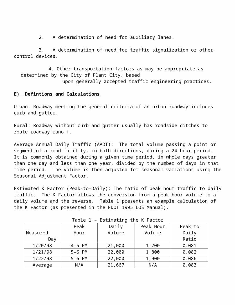
Chapter 10
Stormwater Management
A) Forward
It is the intent of this section to mitigate the impact of offsite impacts as a result of construction, modification or alteration of stormwater management systems, land alteration or development. No construction, modification or alteration to existing or construction of new stormwater management facilities shall be performed within the City that does not meet the requirements of this manual.
B) Definitions
Adverse Impacts: Any modifications, alterations, or effects on a feature or characteristic of water bodies or flood prone lands including their quality, quantity, hydrodynamics, surface area, species composition, living resources, aesthetics or usefulness for human or natural uses, which are or potentially may be harmful or injurious to human health, welfare, safety or property, biological productivity, diversity or stability, or which reasonable interfere with the enjoyment of life or property including outdoor recreation or cause damage to adjacent property owners. The term includes secondary and cumulative as well as direct impacts.
Construction site: The area disturbed by the project construction. This includes but is not limited to project site, access drives, roads, storage areas either on or offsite, other ancillary areas where materials are stored, staging areas and impacted surface water management systems.
Borrow Pits: An excavated area where material has been removed for use as fill at another location.
Channel: A natural or artificial water course with a defined bed and banks that conveys flowing water at any time.
Closed drainage basin: A drainage basin with no structural outfall. Discharge occurs from percolation, evaporation and evapotranspiration.
Construction: The act of altering or disturbing land or vegetation in preparation for development, or any action or activity which results in an alteration or disturbance of either land, vegetation, or existing structrures or new structures.
Conveyance: Transport of stormwater.
Detention Pond: A stormwater pond designed to capture and discharge stormwater at a reduced rate.
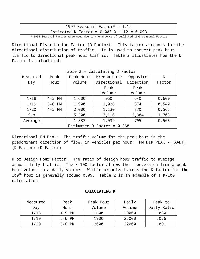
Developer Any person who acts in his own behalf or as the agent of an owner of property and engages in alteration of land or vegetation in preparation for construction activity, development, or any action or construction activity which results in a disturbance of either land, vegetation or existing structures.
Ditch: An open stormwater conveyance with side slopes steeper that three units horizontally to one unit vertically (3:1)
Floodplain: Area inundated as a result of the 100 year 24 hour event as indicated on the latest Flood Insurance Rate Map as approved by the City.
Project Site: For the purpose of this section project site shall mean the disturbed area. The disturbed area shall be either temporarily disturbed or permanently disturbed.
Swale: An open stormwater conveyance with side slopes not steeper than three units horizontally to one unit vertically (3:1)
C) Stormwater Management
1. No development may be permitted within the City that does not meet the design criteria of this section.
2. Design Criteriaa. The minimum attenuation design criteria is to match the rate of runoff from the pre
development condition and the post development condition for the 25 year 24 hour storm event. Which for the purposes of design within the City shall be 7.5 inches of rainfall. This shall be demonstrated by using the “SCS Method” of calculating runoff.
b. Proposed wet detention systems shall provide treatment for the first 1 inch of runoff from the project site in addition to 2.a. above.
c. Proposed dry detention systems shall provide treatment for the first ½ inch of runoff from the project site in addition to 2.a. above. Additionally, dry pond design shall have a minimum 1ft clearance between the seasonal high water elevation and the pond bottom.
d. Treatment systems designed with sidebank filter drains shall provide treatment for the first 1 inch of runoff from the project site.
e. Sites with a total project area of 10,000 sq feet or less shall not be required to meet attenuation criteria set forth in this section.
f. Recovery times for all stormwater management systems shall be consistent with the requirement of the Southwest Florida Water Management District’s Basis of Review.
g. Sites requiring attenuation design shall route the 100 year 24 hour storm event (11.5 inches) through the system and demonstrate that the proposed system can properly function under this event.
h. A minimum 1’ of freeboard shall be provided in the pond for the design storm event.
i. Impacts to floodplains shall be mitigated “cup for cup” or equivalent volume.j. Stormwater management systems designed to discharge into floodways or that
cause a net impact to the floodplain during the 100year 24 hour event shall attenuate the 100year 24 hour pre/post condition.
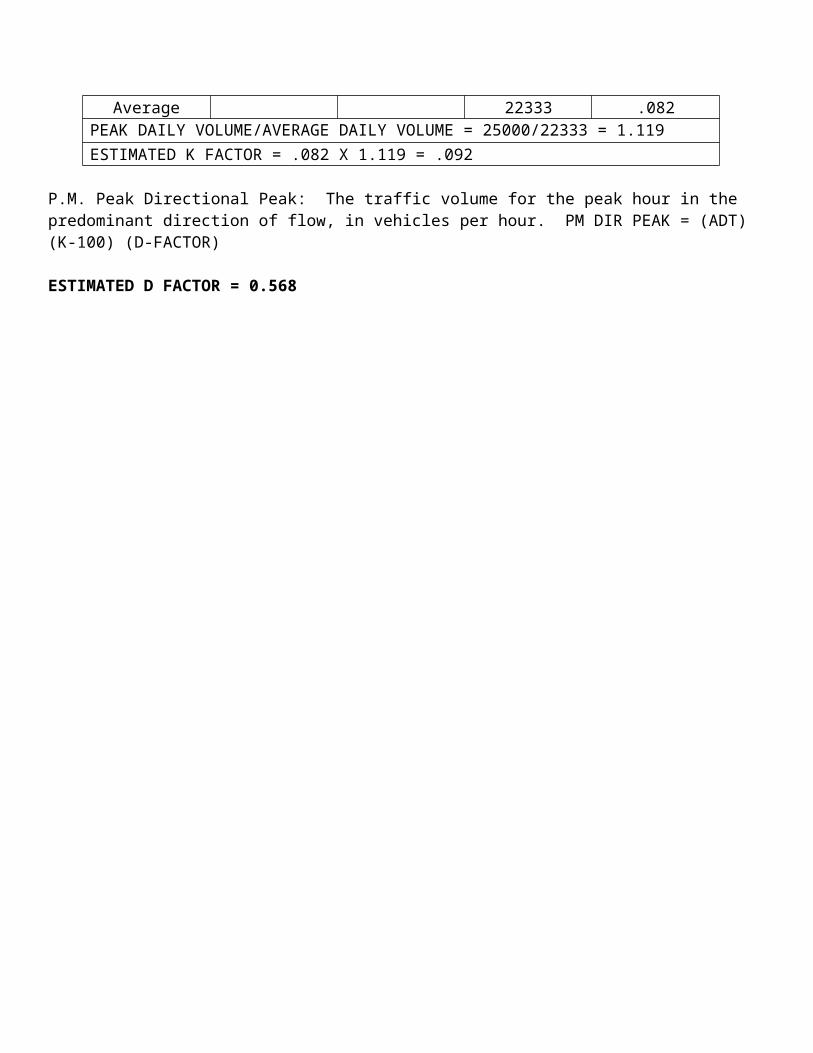
k. Development within closed basins shall be designed contain the 100 year 24 hour post development storm event with no pre development match.
l. Floodplain mitigation shall not be designed within stormwater management ponds. All floodplain mitigation must be contained on the project site and within flood plain mitigation areas.
m. Floodplain compensation shall be calculated from the seasonal high groundwater table elevation or if contiguous to a wetland or water body the seasonal high water elevation whichever is greater.
n. There shall be no encroachment of floodways within the City.o. Credit for existing impervious areas shall be granted for unpermitted sites that exist
prior to 1984. Impervious areas not previously permitted or exempt by the Southwest Florida Water Management District but constructed post 1984 shall not be granted credit existing impervious.
p. All control structures shall be monolithic concrete. q. No portion of any structure shall be constructed within the 100 year floodplain that
does not provide compensating storage within the same basin.r. No stockpiling of material, grading, excavating, and/or other act(s) either
temporary or permanent affecting drainage shall change the surface drainage patterns to the detriment of neighboring properties or public rights of way.
s. No applicant for permitting under this section shall receive credit for historic basin storage. The volume of historic basin storage shall be in addition to the post development storage volume and shall not be attenuated.
t. Above ground impoundments shall provide a mounding analysis indicating the location of the phreatic surface and a demonstration that the phreatic surface is sufficiently depressed to not cause failure of the impound or other offsite impacts.
u. All storage, treatment and attenuation requirements shall be met within a pond suitably sized for the designated use. No storage or credit is allowed for conveyance or any area above the top of inlet elevation.
v. Design of a stormwater management facility shall be consistent with current or future City stormwater masterplan and the City’s MS4 permit.
w. Bridges and culverts beneath City streets (public or private) shall be designed to pass the 100 year 24 hour event without cresting the roadway.
x. Roadside collection systems shall be designed using the rational method or modified rational method and shall be designed so that the hydraulic grade line for the 25 year 24 hour event does not exceed the gutter elevation.
y. Design tailwater conditions shall be based upon the maximum stage of the receiving water body for the 25 year 24 hour design storm or the 100 year 24 hour event depending on the design event.
z. Vertical walled ponds are not authorized for any projects that contain a residence.
3. Submittal Requirements
a. The applicant shall submit only plans signed and sealed by a licensed professional engineer in the State of Florida.
b. Provide a survey profile of the path of the gutter flow in 50-foot increments and provide cross sections at every change in the typical section and every 50 feet to the point of inlet into the City system.
c. Wetland survey certified by either the Southwest Florida Water Management District or Hillsborough County Environmental Protection Commission.
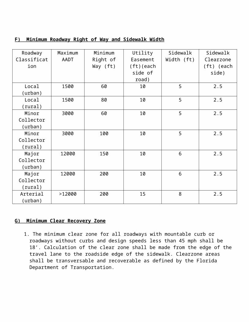
d. Calculations including storm tabulations and pond sizing along with calculations to support all conclusions.
e.D) Permitting Requirements
1. The applicant for stormwater review shall submit proof of compliance with the permitting requirements of the Southwest Florida Water Management District and the EPA requirements for the notice of intent to discharge stormwater or produced groundwater to waters of the State.
2. Army Corps of Engineers permitting may be required for work within or near waters of the State.
E) Exemptions
1. Modifications that result in less than 1000 square feet of additional impervious area shall be exempt from permitting under this section providing the modification will not cause an off site impact.
2. Army Corps of Engineers permitting may be required for work within or near waters of the State.
F) Finished Floor Elevations
1. All new subdivisions, new commercial and industrial sites shall be designed with a finish floor 18” above the 100 year flood plain or 18” above the centerline of the roadway located directly in front of the property whichever is greater. Modifications to this requirement may be made by the City Engineer where no practical purpose is served.
2. New structures where directly adjacent structures are such that the requirement under item F.1. would not be practical and are not located within the 100 year floodplain shall have a minimum elevation of 6” above the crown of road directly in front of the property (taken at the driveway location).
3. Existing structures where additions are proposed and are not located within a designated floodplain may match the finished floor of the addition to the existing finished floor elevation.
G) Erosion Control Plan
1. All sites must have an erosion control plan addressing waterborne erosion, windblown erosion, and sediment deposited by vehicles entering or leaving the site. The erosion control plan may consist of, but is not limited to, either a temporary system installed by the applicant or a twenty (20) foot wide buffer of undisturbed vegetation. In all instances, the plan must remain in effect until the site is permanently vegetated.
H) General Excavation and Pond Requirements
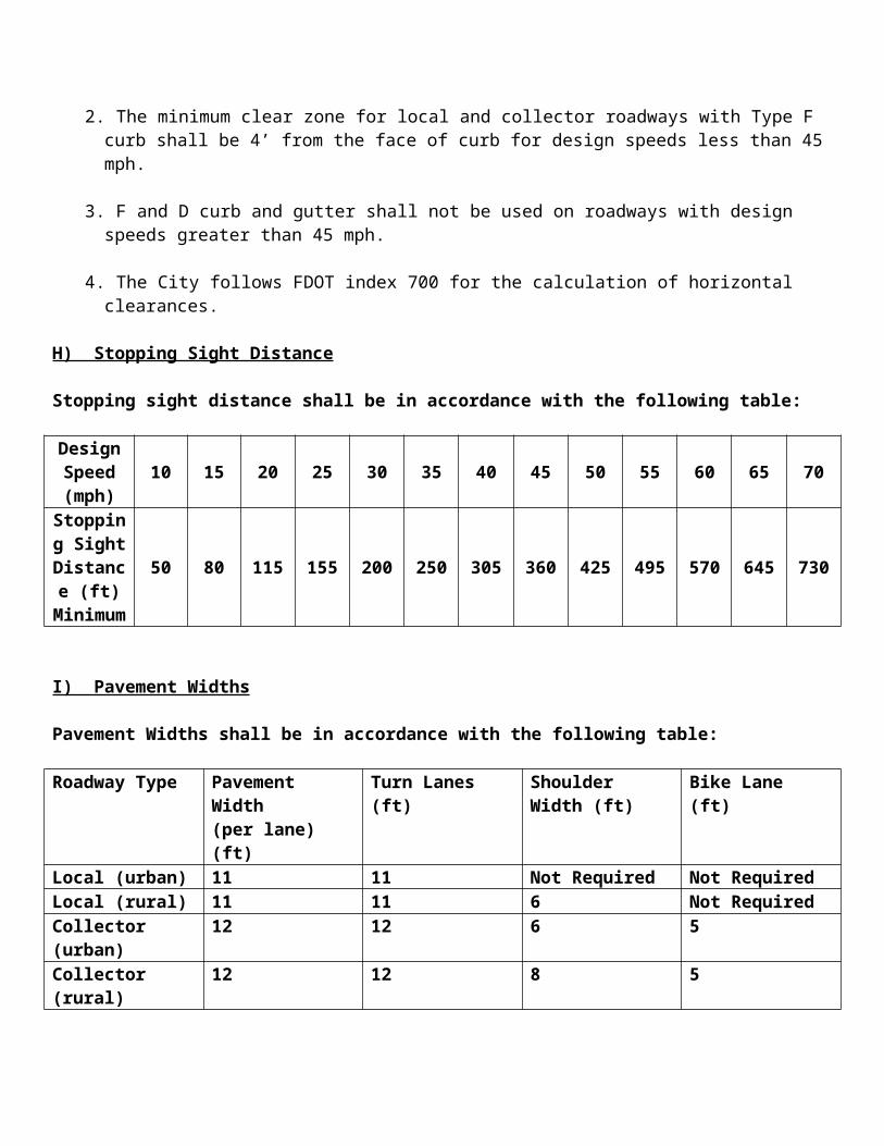
1. Setback – The minimum horizontal setback from any property line to the top of bank is five (5) feet. The minimum horizontal separation from any sidewalk, normal pedestrian area, slab or grade type patio, vehicle driving or parking area or leisure activity area to the top of bank for any excavation is five (5) feet unless separated from the excavation by a fence (as specified below). Maximum slope within a setback area is one (1) foot vertical to eight (8) feet horizontal.
2. Side Slope – Side slopes shall not promote erosion, shall be easily maintainable, grassed and shall be appropriate for the soil conditions. The maximum allowable side slope for an excavation without a fence is one (1) foot vertical to four (4) feet horizontal. Ditches may have a maximum side slope of (1) foot vertical to two (2) feet horizontal providing all the clearzone requirements can be achieved. The requirement for ditch paving shall be in accordance with section G of the transportation section of this manual.
3. Depth – Depressions less than or equal to two feet shall be considered a function of grading.
4. Grading – The minimum slope for lot grading shall be 1% for all slopes
5. Fencing – All pond excavations with side slopes steeper than one (1) foot vertical to four (4) foot horizontal (1:4) shall be fenced, whether the excavation is on going or complete. The fence shall be a Florida DOT Type B Fence or an equivalent safety fence and be constructed along the outer perimeter and on top of the maintenance berm. Ingress and egress for pond maintenance shall be provided, but restricted by lockable gates of adequate size to allow for the easy passage of necessary maintenance equipment. If chainlink fencing is used, it shall be green or black vinyl coated.
I) Certificate of Occupancy
1. No certificate of occupancy shall be granted until the stormwater management system is complete. Projects requiring only culverts or minimum stormwater controls such as ditching shall have all works complete and approved by the City prior to issuance of a certificate of occupancy.
2. No certificate of occupancy shall be granted until all as built drawings have been submitted and approved. All easements, and certifications by the engineer of record shall be submitted.
3. For phased developments the complete stormwater management system for all phases of construction shall be complete in accordance with this section prior to issuance of any certificate of occupancy for the project.
J) Easements
1. The minimum stormwater easement for conveyance shall be at least twenty (20) feet in width and shall remain unobstructed for the life of the easement.
2. No permanent structures shall be authorized in drainage easements except for those structures needed for the operation and maintenance of the stormwater management
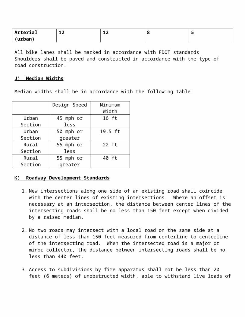
system. Sidewalks, driveways, impervious surfaces, patios, decks, air conditioners, structures, utility sheds, poles, fences, signs, sprinkler systems, trees, shrubs, hedges, landscaping plants (other than grass), concrete foundations, pools, walls or buildings are prohibited within any drainage easement or right-of-way.
3. If in the process of retrofitting, replacing and/or otherwise maintaining a stormwater management facility within a drainage easement or right-of-way, an illegally constructed permanent structure(s) or improvement(s) is encountered, the cost of removal, replacement (elsewhere) or disposal of the structure or improvement shall be borne by the affected property owner.
K) Canals and Ditches
1. If an existing ditch within the City accepts stormwater runoff from public rights-of-way, then crosses private property prior to discharging to a receiving body or other public system, the City Engineer may require any proposed onsite relocation or alteration of such private property ditches to be accomplished using suitably sized pipes or ditches for the full length of the relocation or alteration. Review and approval of such proposed relocations or alterations along with dedication of an appropriately sized drainage easement will be required by the City Engineer.
2. The City may require an applicant to provide the City with an easement over existing drainage features such as floodways, canals and streams or other conveyance providing that conveyance is of local significance and conveys flows through the property or to historic storage areas either on or off site.
L) Private Stormwater Management Facilities
1. Private developments that will contain private stormwater management facilities shall provide proof of perpetual maintenance for the system.
2. Private developments that contain private streets shall have responsibility for the operation and maintenance of the stormwater management system with the exception listed below.
3. Stormwater management systems for public streets in developments where a stormwater management system has been installed that is the responsibility of an association or similar maintenance entity shall have responsibility for the operation and maintenance of the system from the right of way line.
4. Where an emergency condition exists or the association or other entity has responsibility for operation and maintenance of the stormwater management system and has not exercised their duty. The City may perform such activities as necessary to assure the continued function of the system. The association or entity shall be responsible for all cost associated with this activity.
M) Discharge to City Streets
1. A positive outfall to a public “curb and gutter” street can be claimed if gutter flow does not intrude onto other private property meets the City design standards for spread during the 25 year 24 hour and 100 year 24 hour events.
2. Spread calculations shall be performed in accordance with the FDOT Drainage Manual latest edition.
N) Residential Lot Grading
1. All residential lots shall be type A, B or C. Type A lots shall be preferred and shall direct drainage to the front of the property, Type B and C lots shall include rear yard swales and shall direct the lot drainage to the rear (Type C) or half to the rear and half to the front of the property (Type B).
2. Lot grading plans shall be prepared by a licensed Florida professional engineer, who shall sign and seal the plans.
3. All lot grades shall have a minimum 1% slope.
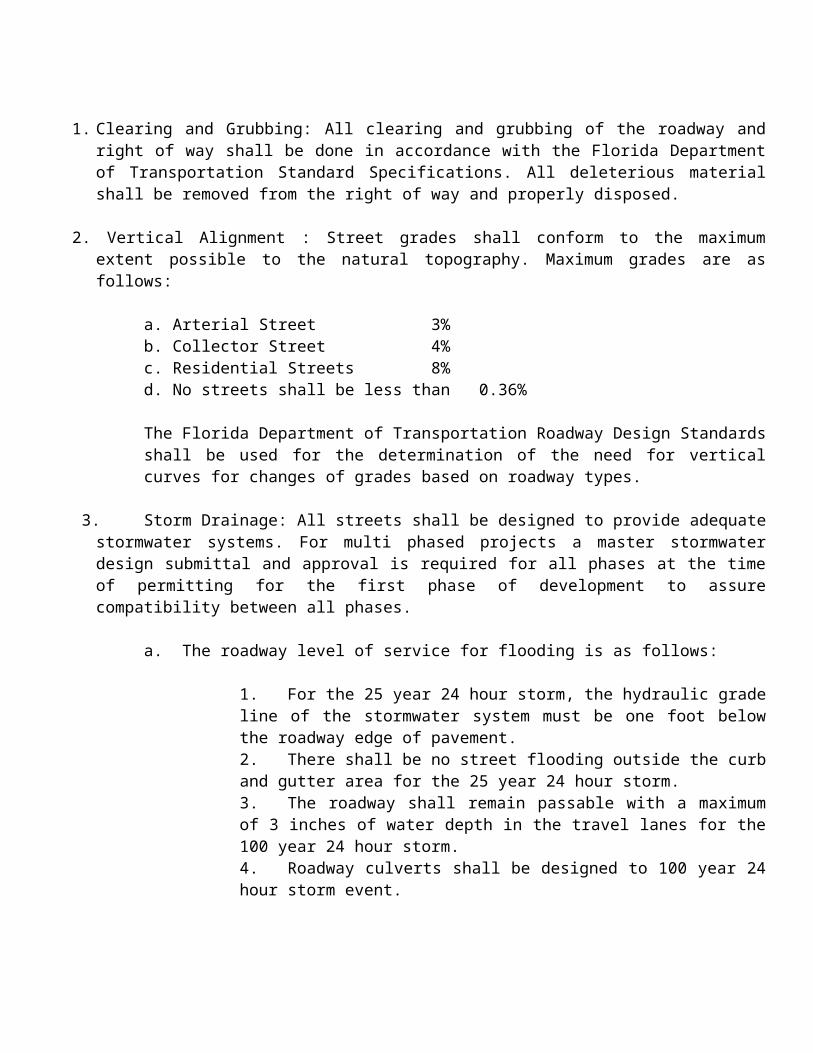
Chapter 11Water Distribution
A) Forward
1. All water distributions systems designed for use in the City shall be signed and sealed by a professional engineer licensed in the State of Florida.
2. The water distribution system shall be designed to provide looping of the water system to provide redundant water supply and avoid water quality issues. Water distribution system shall be designed and modeled using WaterCad or compatable type of water modeling software approved by the City Engineer. Prior to approval of any connection to the existing water distribution system the applicant must demonstrate that a minimum 1000 gallons per minute fire flow can be maintained at the nearest existing hydrant and at the farthest point in the subdivision or development. Main transmission lines shall be ductile iron pipe as indicated in this section or HDPE. All water transmission lines located with right of ways of collector, arterial and frontage roads shall be ductile iron pipe or HDPE. Alternates to this requirement shall be at the discretion of the City Engineer.
3. The following acronyms apply to this section
ANSI- American National Standards InstituteAPWA- American Public Works AssociationASTM- American Society for Testing and MaterialsAWWA- American Water Works AssociationBac-T- Bacteriological TestingDDCV- Double Detector Check ValveDIP- Ductile Iron PipeDOH- Department of HealthEA- EachFDEP- Florida Department of Environmental ProtectionFDOT- Florida Department of TransportationF&I- Furnish and InstallHDPE- High Density Polyethylene MJ- Mechanical JointNPDES- National Pollution Discharge Elimination SystemOSHA- Occupational Safety and Health AdministrationPVC- Polyvinyl Chloride PipeSDR- Standard Dimension Ratio
B) City Utility
1. All new development within the City shall be required to connect to the City’s water distribution system. All potable wells used for domestic or irrigation shall be plugged and abandoned in accordance with the Southwest Florida Water Management District rules prior to site development.
2. Single family lots not part of a new subdivision are not required to connect to the City water distribution system if they cannot be serviced within 250’.
C) System Sizing
1. The water system distribution system shall be designed for 100% of the peak flow (peak day) plus fire flow. The system shall be designed so that a minimum design pressure of 35 psi shall be maintained within the transmission line at peak flow plus fire flow demand. The maximum velocity in any water line shall be 10 fps.
2. The minimum line size for all water distribution within the City shall be 6 inches.
3. All dead end water lines shall terminate with an approved automated blow off system. The unit will be a Hydro-Guard as manufactured by Environmental Enhancement & Technologies USA, Inc or equal. The unit will be battery powered (9 volt) with a minimum one year operational life.
4. Water lines dedicated to the City shall be installed within public right of way. When no public right of way is available easements dedicated to the City maybe authorized on a case by case basis. The minimum width of easement per individual line shall be 20’. When utility is proposed to be located within a private right of way (ex. CSX), the applicant shall bear the full cost of acquiring all license’s, insurance and indemnities required by the property owner and the City.
5. The City requires that the potable water transmission system be looped for residential developments over 50 units to provide continuous service in the event of an outage.
6. The routing of the water distribution system shall be in accordance with the City’s master plan. In the event that development occurs outside of the City master plan the City Engineer shall determine the location and looping requirements of the water system.
7. The City may require upsizing of the water system or an extension beyond the development points of connection.
8. The City Engineer shall determine the location of all connection points to the City distribution system.
9. Valve spacing:
a, Water valves shall be spaced according to the following schedule:
Main Size Maximum Valve Spacing6” 600’8” 800’10” 1000’12” 1200’16” 1600’
b. Additional valving maybe required based upon proposed future development plans or as required by the City Engineer.
c. T’s shall be constructed with 3 way valveing, crosses shall have 4 way valveing.
10. Water Meters General
a. All water meters shall be purchases through the City. Developments may submeter using a non City meter providing all requirements of the State of Florida Health Department are met.
b. All public water meters shall be installed within a utility easement on the development side of the sidewalk. The following developments shall be serviced as follows:
Type of Development Public on site Utilities Private on site UtilitiesSingle family residential Individually Metered Individually Metered
Townhomes Master Metered Master MeteredCondo Master Metered Master Metered
Commercial < 6 Units Individually Metered (Bank) Individually Metered (Bank)Commercial > 6 Units Master Metered Master Metered
Industrial Individually Metered N/A
c. Meter selection: Water meters shall be purchased and installed by the City. The following charts shall be utilized to size water meters for domestic use.
Water meter sizing:
Meter Size Capacity in Number of Condo/Apartment Units
Capacity in Number of Commercial ERU
Capacity in 1000 sq ft of Irrigation
5/8” 0-2 0-3 0-41” 3-5 4-10 5-11
1 ½” 6-12 11-26 12-212” 13-24 27-60 22-34
METER SIZE CONTINUOUS FLOW PRESSURE LOSS5/8” 15 GPM 3.5 PSI1” 50 GPM 6.5 PSI
1 ½” 80 GPM 4.8 PSI2” 100 GPM 3.3 PSI3” 350 GPM 4.3 PSI4” 600 GPM 3.5 PSI6” 1350 GPM 14.3 PSI
11. Commercial or Industry Meters
a. Three inches (3") and larger, must have a minimum by-pass as shown below:
Three inch (3") & four inch (4") meter-Two inch (2") minimum by-pass.Six inch (6") & eight inch (8") meter-Four inch (4") minimum by-pass.
12. Compound Meters
a. The applicant for water service may utilize a compound meter for service providing the required compound meter size is available. The applicant for a compound meter shall notify the Engineering Department at the start of the review process. The delivery time for compound meters is six weeks.
b. Compound Water Meters
METER SIZE CONTINUOUS FLOW PRESSURE LOSS8” 3500 GPM 10.3 PSI
13. Water service line size:Meter Service Line Size
Single 5/8” 1”Dual 5/8” 2”Single 1” 1”Dual 1” 2”
Single 1 ½” 2”Dual 1 ½” *Single 2” 2”Dual 2” *
* Each meter must have its own service line.
14. Fire Flow
d. The City requires a minimum of 1000 gpm at each fire hydrant located in the development. The applicant shall demonstrate during the review process that 1000 gpm can be maintained at each hydrant in the system during peak demand (peak day) and shall maintain a minimum of 35 psi in the distribution system.
b. Fire Line Water Meters
METER SIZE CONTINUOUS FLOW PRESSURE LOSS4” 1000 GPM 8.5 PSI6” 2000 GPM 9.4 PSI8” 3500 GPM 13.4 PSI10” 5500 GPM 12.5 PSI
15. Fire Hydrants
a. Private fire hydrants shall be maintained by the owner of the proposed development. Annual certification of the hydrant may be performed by the City and charged to the owner. All hydrants shall be placed as close to the right of way line as possible and shall have a minimum 6’ unobstructed radius.
D) Installation, Inspection, Clearance
1. Notification:
a. Contractors installing, or performing any work that impacts the water distribution system shall provide 72 hours notice prior to the City of Plant City. The City will coordinate the shutdown of water system as necessary to facilitate the construction, however all shutdowns timing and duration will be determined by the City with contractor input.
b. All installations shall be in accordance with manufacturers specifications and shall be warranted by the developer for 13 months from the date of acceptance by the City.
c. Connnections to the distribution system: All connections to the distribution system shall meet City of Plant City testing requirements, all requirements of the Hillsborough County Health Department, and the State of Florida Department of Environmental Protection.
d. The contractor shall furnish and install the tapping sleeves and valves to existing water mains under City supervision. No size on size taps will be permitted. When a size on size connection is required a tee will be required with 3 way valveing.`
Water Distribution System Technical Specifications
A) Materials
1. All materials shall be new and unused and meet AWWA/ANSI standards.
B) Contractor
1. Only State of Florida licensed underground utility contractors shall install pipe under this section.
C) Pipe
1. All pipe, and fittings intended for conveying or transmitting domestic potable water shall be in conformance with ANSI/NSF Standard 61-Drinking Water System Components-Health Effects
2. All pipe, and fittings intended for conveying or transmitting domestic potable water shall be designed for a minimum working pressure of 150 psi plus a (100) psi minimum surge allowance and a 2:1 safety factor on the sum of the working pressure plus surge pressure.
3. No pipe smaller than 6” shall be used in the distribution system unless approved by the City Engineer.
4. Ductile iron pipe shall conform to ANSI/AWWA Standard C151/A21.51 latest revision-Ductile Iron Pipe Centrifugally Cast in Metal Molds. Pressure Class 350 shall be used for 4” – 24” diameters and Pressure Class 250 shall be used for 30” through 64” diameters. Class 53 pipe shall be used on flanged applications.
a. Ductile iron pipe shall be cement lined and seal coated in accordance with ANSI/AWWA Standard C104/A21.4 latest revision. The pipe shall be adapted for use with Class 350 fittings through 24” and for Class 250 fittings in sizes 30” and over.
b. Flanged ductile iron pipe shall only be used in above ground or vault applications. c. Push on ductile iron pipe shall be used in underground applications.
d. The class or nominal thickness, net weight without lining, and casting period shall be clearly marked on each length of pipe. Additionally, the manufacturer's mark, country where cast, year in which the pipe was produced, and the letters "DI" or "Ductile" shall be cast or stamped on the pipe.e. Newly installed ductile iron water mains shall be disinfected in accordance with the latest revision of AWWA Standard C651 prior to placing in service.
5. Installation
a. No work shall begin until the Contractor has a copy of the approved engineering plans and the HRS permit. Failure to keep these items on site shall result in stoppage of work.
b. Any material in the bottom of the trench declared unsuitable by the City Engineer shall be removed and replaced by approved materials.
c. When the original material in the bottom of the trench is found to be suitable for supporting the water line, the trench bottom shall be accurately rounded and graded to provide continuous uniform bearing of at least one-fourth (1/4) of the pipe circumference on undisturbed soil. At bells or other joint locations excavate only to the extent necessary to permit accurate work in making joints and to make sure the entire length of the pipe is being supported without imposing undue loads on the bell or joint. If by error the trench bottom is disturbed the bottom soil must be compacted to 95% dry density as determined by modified proctor and the pipe bed prepared as above. When additional dirt needs to be added to the trench bottom, either because of over digging or because of replacing unsuitable materials, the bottom must be compacted to 95% dry density and the pipe bed prepared as above. A density of 98% shall be required under all curbing and roadways.
d. No new water line construction shall be connected to any existing water line in the City without the direction of the City Engineer. Upon approval by the City Engineer the water line shall be connected in such a way that there is a new valve separating the existing from the newly placed line. In the event there is an existing valve it shall meet AWWA standards. If the Contractor chooses to use the existing valve, it must be tested in the presence of the Inspector. If the valve fails Contractor may attach a new valve to the existing valve. Prior approval is needed from the Engineering Division. At this time the valve becomes the property of the City and will be locked off. The valve shall not be opened at any time during construction by other than City personnel who has the approval of the City Engineer. Failure to comply with these rules may result in the disconnection of the new line and the Contractor shall install a reduced pressure back flow assembly. All costs shall be the Contractor's responsibility. It is the Contractor's responsibility to make exploratory excavations and/or use other methods available to locate lines.
e. This connection is only for the flushing and testing of the new line. Any water needed for construction purposes shall be obtained by the use of a fire hydrant meter/back flow assembly. Fire hydrant/ backflow assembly will only be installed with approved work order from Engineering.
f. Extreme caution shall be used in the handling of pipe. The ends should not dig into the prepared pipe bed. The entire inside of the pipe and the outside ends of the pipe must be clean before joining.
g. Pipe shall not be joined when there is water in the trench; the trench must be dry. The joining ends of the pipe must be clean before they are joined and the open end of the "in place" pipe must be covered and protected to prohibit any foreign materials from entering the pipe.
h. After placing a length of pipe in the trench, the spigot end shall be centered in the bell, the pipe forced home, brought to correct alignment, and covered with an approved backfill material. If PVC pipe is installed, an insulated copper wire (AWG-12) shall be wrapped around the pipe and be taped every ten feet for location purposes. Each fire hydrant shall have one wrap of the wire around the barrel located at the final grade and connected to the wire on the water main.
i. When "Push On" type joint is used the end of each pipe must be clean, the gasket must be clean and correctly seated in the gasket grove in the bell, the spigot and only lubricated with the manufacturer's approved lubricant, and the spigot end slid into the bell end until the two (2) are seated. Comply with the manufacturer's mark for correct seating if marked on the spigot end of the pipe. All installations shall meet the City specifications and standard drawings along with the manufacturer's recommendations.
j. All other approved type connections for pipe and fittings must be clean before joining and joined according to standard practices, manufacturers recommendations, and City standard drawings specifications.
k. Trenching shall not take place within the root zone of trees with a trunk diameter of 6 inches or larger. The root zone shall be defined as the greater of 1) the dripline of the tree or 2) a circular zone extending outward from the base of the tree a distance equivalent to ½ foot for every inch of trunk diameter as measured 4-1/2 feet above; natural grade.
6. Standard Separation
a. Sewers crossing under water mains shall be laid to provide a minimum vertical distance of eighteen inches (18") between the invert of the upper pipe and the crown of the lower pipe. Where this minimum separation cannot be maintained, the crossing shall be arranged so that the sewer pipe joints and water main joints are equidistant from the point of crossing with no less than ten feet (10') between any two (2) joints. Alternatively, the sewer main may be placed in a sleeve to obtain the equivalent of the required ten feet (10') separation. If the eighteen inch (18") vertical separation can not be achieved, both water and sewer lines shall be Ductile Iron Pipe.
b. Where there is no alternative to sewer pipes crossing over a water main, the criteria for minimum separation between lines and joints shall be determined by the City Engineer and the Hillsborough County Health Department.
7. Backfilling:
a. After completion of bedding, the pipe may be backfilled according to specifications. Backfilling shall occur before the pressure test is conducted. After the pressure test is completed and approved by the City Engineer, the pipe backfilling can be completed according to the procedures in this section. Cover materials shall be sand, pit run gravel, or previously excavated granular material free from clay lumps, large stones and rocks, and debris.
b. All cover material shall be carefully deposited in six inch (6") layers to avoid damage to the pipe and shall be compacted to 98 percent modified proctor density. The cover material shall be deposited simultaneously on both sides of the pipe. If larger compaction equipment is available, lifts may be twelve inches (12"). Prior approval from the City Engineer is needed.
c. After bedding and cover have been placed to a level one foot (1') above the top of the pipe, backfilling shall be in accordance with the following procedures.
d. Do not backfill until new concrete has properly cured, coating has been approved, and any required test has been accepted.
e. Exercise care during backfilling operations to avoid any puncture, break, or other damage to the pipe line and fittings.
f. Fill may be deposited by dragline, bulldozer, or other mechanical equipment if care is taken during backfilling.
g. The backfill shall consist of the excavated materials when approved by the City Engineer. Backfilling of trench with broken concrete, asphalt or other large lumpy materials will not be permitted.
h. If the trench is in an unimproved area the backfilling can be finished with tamping and by having the fill rounded off on top. Required density is 95% modified proctor.
i. In areas where streets, sidewalks, drives, or other improvements are to be made the backfill hall be compacted in six inch (6") or twelve (12") layers to give an overall compaction of 98% of maximum dry density (modified proctor)
j. If the materials are suitable and with the City Engineer's permission the backfill may be compacted hydraulically. In this case the City Engineer will determine when the trench may be paved over.
k. The Contractor shall not backfill over any new construction or uncovered existing utility without permission of the City Engineer or his/her designee.
l. In any case where construction is backfilled without the City Engineer's permission, the Engineer shall have the right to require the Contractor to uncover this work at the Contractor's expense.
m. When the Contractor works on a day that is not the City Engineer's regular work day or at a time the City Engineer cannot be present, the Contractor shall not backfill any construction until the Engineer returns and approves the backfilling.
n. The City Engineer's approval for backfilling is not an acceptance of the covered construction and does not relieve the Contractor of meeting the requirements contained in this specification.
D) Fittings
1. Ductile Iron fittings shall conform to ANSI/AWWA Standard C110 A21.10 latest revision or ANSI/AWWA Standard C153 A21.53 latest revision, with the joints meeting the requirements of AWWA C111 latest revision. Fittings 4” and larger shall be cement lined and seal coated in accordance with ANSI/AWWA Standard C104 A21.4 latest revision.
E) Joints General
1. Joints for bell and spigot ductile iron pipe and fittings shall conform to ANSI/AWWA Standard C111 A21.11 latest revision. Mechanical joint or push on joint shall be rubber gasket compression type. Special fittings and restrained joints shall be considered for specific applications subject to the approval of the City Engineer. Joints for flanged ductile iron pipe and fittings shall conform to ANSI/AWWA Standard C110 A21.10 latest revision.
F) Push on Joint Pipe
1. Push on joint pipe shall be furnished with all joint accessories and shall include all gaskets and lubricants in sufficient quantity for proper assembly. All gaskets shall be made of EPDM rubber.
a. All push on joint ductile iron pipe shall be manufactured by U.S. Pipe, American Pipe, or Clow/McWane.
2. Restraint devices for push on type joint shall be U.S. Pipe “Field Lok” Gasket or American “Fast Grip” Gasket.
3. Manufactured restrained joint pipe shall be American Ductile Iron “Flexring”, U.S. Pipe “TR-Flex” or Clow “Super-Lok”
G) Mechanical Joint Pipe
1. Mechanical joint pipe shall be furnished with all joint accessories and shall include all gaskets, ductile iron glands, bolts, nuts, and lubricants in sufficient quantity for proper assembly. All gaskets shall be made of EPDM rubber.
2. Wedge action restraint for ductile iron mechanical joint pipe shall be EBAA Iron “Megalug Series 110-SD” or approved equal.
H) Flange Joint Pipe (Special Approval only)
1. Flange joint pipe shall be furnished with all joint accessories and shall include all gaskets, ductile iron glands, bolts, nuts, and lubricants in sufficient quantity for proper assembly. All gaskets shall be made of EPDM rubber.
2. Ductile Iron flange joint restraint shall be EBAA Iron “Megaflange Series 2100” or “1000” EZ flange.
I) Flexible Joint Pipe
1. Flexible joint pipe shall be push-on, ball and socket, freely deflecting, and restrained using a corrosion resistant locking device. Thickness class shall be as follows:
Diameter Min. Thickness Class6” 548” 5512” 5616” 57
2. The joint shall be capable of a full 15º free deflection with no reduction in waterway.
3. Flexible joint pipe shall be American Ductile Iron “Flex-Lok Boltless Ball Joint Pipe” or U.S. Pipe “USI FLEX Boltless Flexible Joint Pipe”.
J) Services
1. Corporation Stops shall be three-fourths inch (3/4") minimum, thru 2" bronze with AWWA tapered threads. Approved Ford Model #F-1000 or equal.(ground key. Top)
2. Service lines: Service lines shall be HDPE.
a. All services installed under roads shall be encased in a minimum two inch PVC Schedule 40 sleeve. A singe three inch (3") PVC Schedule 40 sleeve may be used to encase two 1” service laterals.
b. Polyethylene extrusion compound from which the PE pipe and tubing are extruded shall comply with the applicable requirements for the Type III, color and UV code E, Class C, PE 3408, very high molecular weight polyethylene plastic material
manufactured in accordance with AWWA C901, latest revision, as specified in ASTM D1248. HDPE tubing shall have a color and ultraviolet code E and a minimum cell classification of 334434E as specified in ASTM D3350.
c. All polyethylene tubing shall be SDR-9 200 psi. The average outside diameter, inside diameter, minimum wall thickness and respective tolerances shall be as specified in ASTM D2737 and ASTM D2239.
d. Polyethylene tubing shall be blue and have UV color stabilizers so that the pipe is not affected in color or flexibility for a minimum of 4 years. Environmental stress testing
shall be in accordance with ASTM D1693 and shall have no failures after 5,000 hours of duration.
3. Curb stops shall be full port and have a flow passage area equivalent to the fitting outlet flow area.
a. Curb stops shall be ball valve, roundway, with check, with a full port opening ball no less than 1 “. Curb stops shall be provided with padlock wings cast on stop body and operating tee cap to provide for locking the stop in closed position. Curb stops for polyethylene services shall have an inlet connection with a compression joint and an outlet connection with female iron pipe thread, as manufactured by Ford Meter Box Company B41W or approved equal.
4. Domestic meters shall be provided by the City at the applicants expense.
5. Commercial or industry meters shall be provided by the City at applicant's expense.
6. Service clamps shall be double strapping used only for water lines one and one-quarter inch (1 1/4) and two inch (2") in diameter. Approved Smith/Blair Model #313 with tapered threads or equal. Lines larger than two inches (2") shall use Smith/Blair Model #622 or equal.
7. Meter box shall be three-fourths inch (3/4") through one and one-half inch (1 1/2") precast concrete with full top opening. Cover shall be cast iron.
K) Exterior Coating
1. Shall be bituminous or an asphaltic coating meeting the requirements of the pipe manufacturer's specifications and ANSI A21.51/AWWA C110.
L) Tapping Sleeves:
1. All fittings shall conform with ANSI and AWWA specifications having a minimum pressure rating one hundred seventy-five (175) psi. Tapping valves shall be furnished with the tapping flange having a raised face or lip design to engage the corresponding recess in the tapping sleeve flange, to be used for potable water systems.
2. All sleeves shall be supplied with proper accessories to include test outlet w/plug, flange (gland), gasket, 304 stainless steel bolts and nuts teflon coated to prevent galling. The finished body shall be a fusion bonded epoxy coating with an average of 12 mil thickness.
M) T apping
1. Size on size taps shall not be permitted. Size on size connections shall be made by cutting in a “t” and providing 3 way valveing.
2. Approved tap Smith/Blair #622 or equal.
N) Restraint
1. Dead end water lines shall require restraint. Restraint shall meet the requirements of the Ductile Iron Pipe Research Association. Refer to this manual for number of feet to restrain. Restraints shall be fast grip gaskets or approved equal.
O) Gate/and Tapping Sleeves (Resilient Seat)
1. The resilient seat gate valve: Shall comply with all requirements of American Water Works Association (AWWA) Standard C-509-80 and the following supplemental requirements.
2. Valves twelve inches (12") and smaller: Shall be bubble-tight at two hundred (200) psi water working pressure. Test pressure shall be twice the rated working pressure and at all times zero leakage will be maintained.
3. All valves: Shall be Class B gray iron body, non-rising stem, water valves suitable for buried vertical mounting.
4. Non-rising stem: Shall be in full compliance with AWWA specifications with cast integral stem collar and furnished of bronze conforming to ASTM B132 Alloy A.
5. Stem nuts: Shall be independent of wedge and shall be of solid bronze conforming to ASTM B62.
6. Gate Valves: Shall have a cast iron wedge completely encapsulated with rubber which is permanently bonded to meet ASTM specifications for rubber metal bond ASTM D429.
7. Stuffing boxes: Shall be o-ring seal type with two (2) rings located in the stem.
8. Low friction torque reduction thrust bearings: Shall be located both above and below the stem collar.
9. All valves: Shall be non-rising stem opening by turning stem left and provided with two inch (2") square operating nut.
10. All tapping valves interior waterway: Shall be full opening and capable of passing a full sized shell cutter.
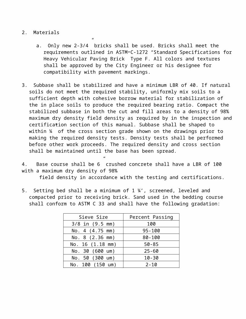
11. All mechanical joints: Shall conform to AWWA Standard C-111, latest revision and all bolts and nuts for mechanical joints shall be high-strength, low-alloy steel in accordance with Section 11-6.5 of AWWA C-111, latest revision. All mechanical joint accessories shall be furnished with the valves.
12. All flange joints: Shall conform to AWWA Standard C-111, latest revision. Flange joint accessories shall be furnished with the valves.
13. All valves: Except those with both end flanged, shall be furnished with operating nuts. Valves with both ends flanged shall be furnished with hand wheels.
14. All tapping valves: Shall have tapping flange having a raised face of lip designed to engage the corresponding recess in a tapping sleeve flange in accordance with MSS
SP60 followed by a mechanical joint end.
15. All tapping valves: Shall be interchangeable with other makes of tapping sleeves. 16. Valve body exterior and cover bolts and nuts: Shall meet specifications ASTM A-307 and be rust proofed. The valve body interior shall have protective epoxy coating meeting AWWA Standard C550-81.
17. All valves: Installed in the water distribution system and water main extensions shall be protected by an adjustable cast iron water valve box, similar or equal to Mueller Model No. H10380. Covers will be marked "Water".
P) Valves
1. Three Inches (3") and Larger (Underground):
a. Valves: Shall conform to the latest revision of AWWA Standard C-509 covering resilient seated gate valves.
b. The valves: Shall be non-rising stem opening by turning stem left and provided with two inch (2") square operating nut.
c. The wedge: Shall be of cast iron completely encapsulated with urethane rubber.d. The urethane sealing rubber: Shall be permanently bonded to the cast iron wedge to
meet ASTM tests for rubber metal bond ASTM D429.
a. Stems: Shall be cast bronze with integral collars in full compliance with AWWA. The stuffing box shall be the o-ring seal type with two (2) rings located above the thrust collar; the two (2) rings shall be replaceable with valve fully open and subjected to full rated working pressure.
b. Two (2) Low torque thrust bearings: Shall be located above and below the stem collar. The stem nut shall be independent of wedge and shall be made of solid bronze. There
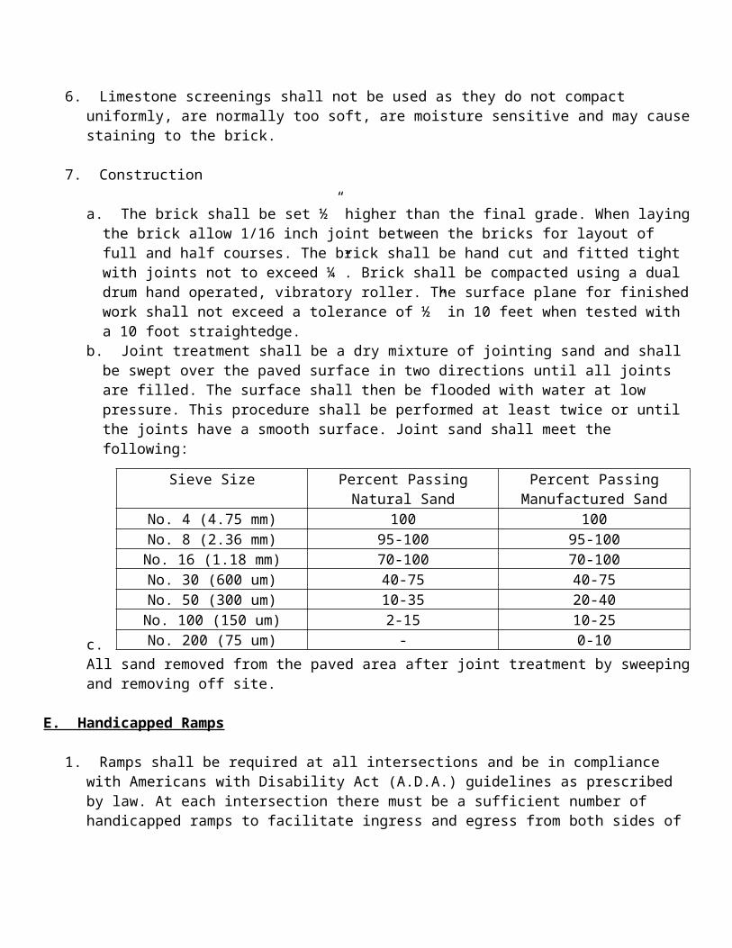
shall be a smooth unobstructed waterway free of all pockets, cavities and depressions in the seat area.
c. The body and bonnet: Shall be coated with fusion bonded epoxy both interior and exterior. Each valve shall have maker's name, pressure rating and year in which manufactured cast on the body. Prior to shipment from factory, each valve shall be tested by hydrostatic pressure equal to twice the specified working pressure.
2. Valves greater than three feet (3') deep
a. Shall require extension to within six inches (6") from top of valve box.b. Valves: Shall be CLOW or approved equal.
3. Smaller Than Three Inches (3") (Underground):
a. AWWA C-800. Valve shall be bronze, 150 pound with female NPT both ends. Approved Ford Model #B11-233 or approved equal.
4. Smaller Than Three Inches (3") (Above ground):
a. Federal specification WW-V054D, valve, gate, bronze (125, 150, and 200 pound) Type III Class B, equipped with operating handle.
5. Ball Valves: Two Inches (2") or Smaller:
a. Bronze body, two (2) piece design six hundred-sixty (660) pound WOG one hundred-fifty (150) pounds psi. End type - threaded. Handle vinyl grip with lever. Ball & stem shall be stainless steel. Federal specification WWV35 Type II Class A Style 3 approved. Nibco or approved equal.
6. Three Inches (3") and Larger (Above ground):
a. Valves: Shall conform to the latest revision of AWWA Standard C- 509 covering resilient seated gate valves.
b. The valves: Shall be non-rising stem opening by turning stem left and provided with handwheel with the word Open and an Arrow cast in the metal to indicate direction to open.
c. The wedge: Shall be of cast iron completely encapsulated with urethane rubber.d. The urethane sealing rubber: Shall be permanently bonded to the cast iron wedge to
meet ASTM tests for rubber metal bond ASTM D429.e. Stems for NRS assemblies: Shall be cast bronze with integral collars in full
compliance with AWWA. OS & Y stems shall be on a bronze bar stock. The NRS stem stuffing box shall be the o-ring seal type with two (2) rings located above the
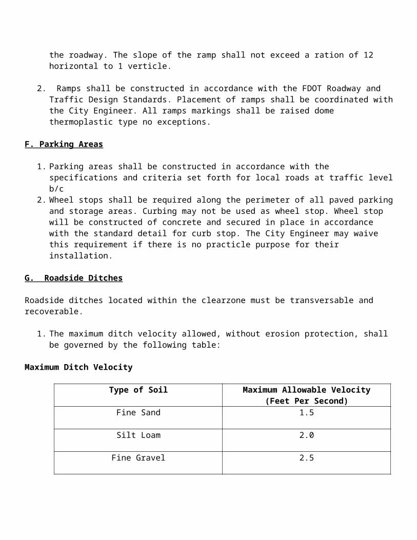
thrust collar; the two (2) rings shall be replaceable with valve fully open and subjected to full rated working pressure.
f. Two (2) low torque thrust bearings: Shall be located above and below the stem collar. The stem nut shall be independent of wedge and shall be made of solid bronze. There shall be a smooth unobstructed waterway free of all pockets, cavities and depressions in the seat area.
g. The body and bonnet: Shall be coated with fusion bonded epoxy both interior and exterior. Each valve shall have maker's name, pressure rating and year in which manufactured cast on the body. Prior to shipment from factory, each valve shall be tested by hydrostatic pressure equal to twice the specified working pressure.
h. Valves: Shall be installed to completely isolate any part of the main line from another. A valve should be between each fire hydrant to limit the outage of one hydrant for any one line break.
i. Valves: Shall be CLOW or approved equal.
Q) Fire Line
1. Valves shall conform to the latest revision of AWWA Standard C-509 covering resilient seated gate valves.
a. The valves shall be rising stem opening by turning stem left and provided with handwheel with the word Open and an Arrow cast in the metal to indicate direction to open.
b. The wedge shall be of cast iron completely encapsulated with urethane rubber.c. The urethane sealing rubber shall be permanently bonded to the cast iron wedge to
meet ASTM tests for rubber metal bond ASTM D429.d. Stems for NRS assemblies shall be cast bronze with integral collars in full compliance
with AWWA. OS & Y stems shall be on a bronze bar stock. The NRS stem stuffing box shall be the o-ring seal type with two (2) rings located above the thrust collar; the two (2) rings shall be replaceable with valve fully open and subjected to full rated working pressure.
e. Two (2) low torque thrust bearings shall be located above and below the stem collar. The stem nut shall be independent of wedge and shall be made of solid bronze. There shall be a smooth unobstructed waterway free of all pockets, cavities and depressions in the seat area.
f. The body and bonnet shall be coated with fusion bonded epoxy both interior and exterior. Each valve shall have maker's name, pressure rating and year in which manufactured cast on the body. Prior to shipment from factory, each valve shall be tested by hydrostatic pressure equal to twice the specified working pressure.
g. Valve shall be CLOW or approved equal.
R) Valve Extension Stems
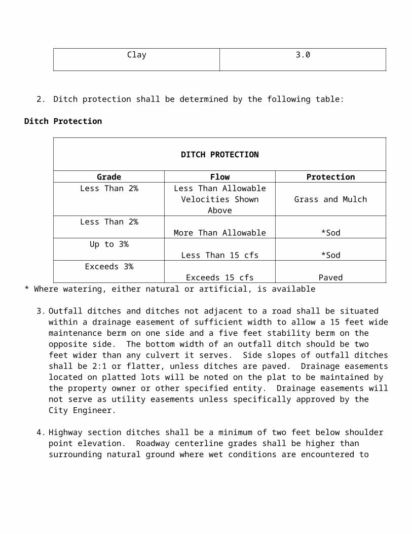
1. Extension stems shall be provided for all valves in buried locations and in other locations where indicated on the Drawings.
2. Extension stems shall be fabricated from solid steel shafting not smaller in diameter than the stem of the valve or from galvanized steel pipe having an internal diameter not smaller than the diameter of the valve stem. Stem couplings shall be both threaded and keyed to the coupled stems and shall be of standard design and construction. Pipe couplings will not be acceptable.
3. Stems for buried valves shall extend to within six inches (6") from top of the valve box. Each extension stem shall be connected to the valve operator. All connections shall be pinned. Each extension stem shall be provided with spacers which will center the stem in a valve box having an inside diameter of five and one-fourth inches (5 1/4"), and shall be equipped with a standard AWWA wrench nut as described in AWWA C500, except where handwheels are indicated.
S) Valve Boxes
1. All buried valves shall be provided with adjustable valve boxes five and one-fourth inches (5 1/4") in diameter with a minimum thickness of three sixteenths inch (3/16") and constructed so that the removable cover will not be thrown out by travel over it. Valve boxes shall be of sound, close grained cast iron, free from flaws and defects, built strong and rugged enough to withstand the shock of street traffic.
2. Valve boxes shall be of sufficient length to operate all valves buried in the ground. Valve boxes shall consist of base, center section, extension piece (if required) and top section with cover.
3. Valve boxes located in unpaved areas shall be Slip Type design to permit movement of the top section with transmitted forces onto the valve body.
4. All valve boxes shall have a 2'x 2'x 4" concrete pad around it. The concrete pad shall have a brass ID tag. The tag shall be 3" in diameter x 1/8" thick. There will be a 1/4x 1/4"x 2" brass tag welded to the center of the circular tag which will be embedded into the valve pad. The tag will be stamped by the Contractor. The information shall read as follows, size of valve and number of turns to fully open.
5. Valve boxes shall be Buffalo Type 2-piece five and one-fourth inch (5 1/4") shaft, Mueller #H-10364 sliding type or equal.
T) Specifications for dry barrel fire hydrants
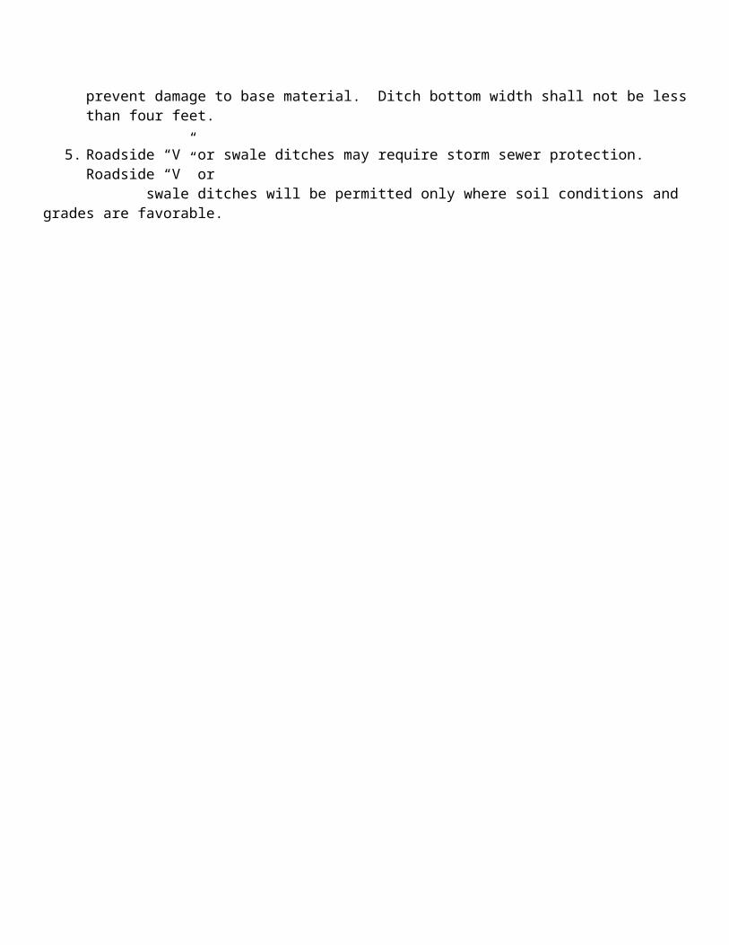
1. Fire hydrants shall conform to the requirements of AWWA standard for Dry-Barrel Fire Hydrants (ANSI/AWWA C-502-85); and in addition, shall be listed by Underwriters Laboratories and Factory Mutual Research Corp. Cast marks or other permanent means shall be used to identify the fire hydrants as conforming to these standards
2. Fire hydrants shall also conform to the following supplementary specifications.
a. Hydrants shall be rated for one hundred-fifty (150) psi operating pressure and tested at three hundred (300) psi per section 5.1 of AWWA C502.
b. The bury length (distance from groundline to insert of the hydrant inlet) shall be as specified hereinafter or as shown on drawing.
c. Nozzles shall have two (2) two and one-half (2-1/2") outlets and one (1) four and one-half (4-1/2) outlet. Nozzle threads shall be National Standard Fire Hose Coupling Screw Thread as described in Appendix A of AWWA C502, unless otherwise specified. Nozzle caps shall be provided with chains and gaskets. Nozzle caps shall have nut configuration the same as the hydrant operating nut. Nozzles shall be reverse threaded into the upper barrel and mechanically locked in place.
d. Hydrant main valve shall be five and one-fourth inch (5 1/4") minimum and shall be of the full compression design, opening against and closing with the pressure. The main valve seat ring shall thread into a bronze sub-seat and all the gaskets sealing the seat ring shall be on a bronze-to-bronze seating surface.
e. Hydrants drains are not required nor permitted. Hydrant sumps are not required.f. Hydrant shall be the breakaway type, with a frangible groundline and rod coupling
designed to break upon traffic impact and prevent further damage to the hydrant and connecting piping.
g. Hydrant operating nut shall be ductile iron and shall be pentagonal in shape, one and one-half (1-1/2") point to flat (AWWA standard). The operating nut shall also function as weather shield. Hydrant shall open left (counterclockwise).
h. Never freeze lubricant shall be used to provide permanent lubrication on the main rod threads. A thermoplastic thrust washer shall be used to reduce friction in the thrust collar while opening the hydrant. Epoxy coat inside of the elbow and bottom plate.
i. The hydrant shall be six inch (6") Mechanical Joint.j. Hydrants shall be painted Tnemec safety yellow, series 2H color BR18.k. Fire hydrants shall be either U.S. Pipe Metropolitan 250, Waterous Pacer WB-67, or
equal.
U) Backflow Assemblies
Note: Backflow assembly devices must be approved by the Water Resource Management Department prior to installation. (See Apendix B)
1. Reduced Pressure Principle Assembly
a. A Backflow Prevention Assembly which includes two (2) independently acting check valves; a hydraulically operating, mechanically independent pressure differential relief valve located between the check valves and below the first check valve; and properly
located resilient-seated test cocks and tightly closing resilient-seated shut-off valves attached to each end of the assembly.
b. The assembly shall meet the standards of the University of Southern California's Foundation for Cross-Connection Control and Hydraulic Research (USC).
c. Approved, watts 909 or approved equal.
2. Double Check Valve Assembly
a. A Backflow Prevention Assembly which includes two (2) internally spring loaded check valves which are installed as a unit between two (2) tightly closing resilient-seated shutoff valves and fitting with properly located resilient-seated test cocks. This assembly may not be used to eliminated a Health Hazard or backpressure that could develop in the downstream piping.
b. The assembly shall meet the standards of the University of Southern California's Foundation for Cross-Connection Control and Hydraulic Research (USC).
c. Approved, Watts series 709 or approved equal.
3. Double Check-Detector Check Valve Assembly:
a. A Backflow Prevention Assembly used for fire systems, Class 1 which includes a line-size Double Check Valve Assembly which is installed between two (2) O.S.Y. resilient seated shut off valves; a specific bypass water meter which registers accurately for only very low rates of flow and shows a registration for all rates of flow; and a meter-sized Double Check Valve Assembly which is installed between two resilient seated shut off valves. This assembly may not be used to eliminate a Health Hazard.
b. The assembly shall meet the standards of the University of Southern California's Foundation for Cross-Connection Control and Hydraulic Research (USC), and approved by Factory Matual (FM) and Underwriter's Laboratory (UL).
c. Approved, Watts 709 DCDA or approved equal.
4. Pressure Vacuum Breaker Assembly:
a. A Backflow Prevention Assembly used for irrigation systems only which includes an independently operating, internally loaded check valve; an independently operating loaded air inlet valve located on the discharge side of the check valve; and properly located resilient-seated test cocks and tightly closing resilient-seated shut-off valves attached at each end of the assembly. This assembly may not be used if backpressure could develop in the downstream piping.
b. The assembly shall meet the standards of the University of Southern California's Foundation for Cross-Connection Control and Hydraulic Research (USC).
c. Approved, Watts series 800 or approved equal.
5. Reduced-Pressure Principle-Detector Assembly:
a. A Backflow Prevention Assembly used for fire systems, Classes 2, 3, 4, 5, and 6 which includes a line-size Reduced-pressure Principle Backflow Prevention Assembly which is installed between two (2) o.s.y. resilient seated shut off valves; a specific bypass water meter which registers accurately for very low rates of flow and shows a registration for all rates of flow; and a meter-sized Reduced-pressure Principle
Backflow Prevention Assembly which is installed between two (2) resilient seated shut off valves.
b. The assembly shall meet the standards of the University of Southern California's Foundation for Cross-Connection Control and Hydraulic Research (USC), and approved by Factory Mutual (FM) and Underwriters Laboratory (UL).
c. Approved, Watts series 909 RPDA or approved equal.
V) Air Release Valve
1. The Air Release Valve shall operate (open) while pressurized, allowing entrained air to escape from the water pipeline, pump or reservoir tank, through the air release orifice. After entrained air escapes through the air release orifice, the valve orifice shall be closed by a needle mounted on the compound lever mechanism, energized by a CONCAVE FLOAT to prevent water from escaping. The air release valve will then stay closed until more air accumulates in it and the opening cycle will repeat automatically.
a. The needle shall be Buna-N for tight shut-off and be resilient to prevent seepage due to pipeline or pump vibrations.
b. The Air Release Valve compound internal lever mechanism shall be all Stainless Steel. All other internals must be stainless steel. The stainless steel float must be CONCAVE and sufficiently buoyant to operate water and be SPURT FREE.
c. The valve shall withstand five hundred (500) psi test pressure and have a three-sixteenth inch (3/16") orifice for operating (opening) pressure up to one hundred-fifty (150) psi. The venting capacity @ one hundred-fifty (150) psi shall be fifty-five (55) CFM.
d. Valve to be APCO 200A Air Release Valve or approved Equal.
2. Installation
a. Where possible the air release shall be installed above the ground. The elevation of the valve shall be installed as directed by the drawing or by the City Engineer. It will be installed in such a manner that it can be serviced without disrupting main line
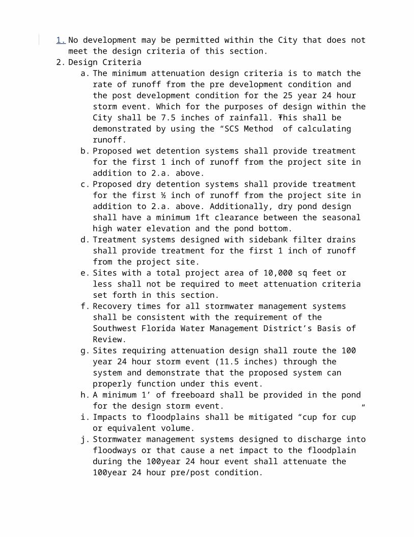
service. Air vents shall be turned down and be made insect free through use of proper screening devices.
b. A shut-off valve shall be installed for servicing the air release valve. The valve shall be a Ford Model B11-233 with lock wing or equal.
X) Procedures For Placing Lines in Service
1. Contractor shall coordinate with the Plant City Engineering Division Division for placing water lines into service. Procedures for placing lines in service are given below:
a. Notify the Inspector seventy-two (72) hours in advance for all scheduled water outages.b. Valves shall not be operated by any person other than Water Division personnel.c. All new mains shall be flushed prior to acceptance to remove any construction
materials and foreign objects in the new main.d. All repairs, modifications and installations not requiring a hydrostatic test shall have all
joints exposed when pressure is applied.
2. No acceptance of connections from new to existing water mains will be allowed until pressure test has been accomplished. The City Inspector will monitor the charging of the new main.
3. The prescribed test of completed work on the main shall be hydrostatic and shall be one and one-half (1 1/2) times the normal line working pressure, but in no case less than one hundred-fifty (150) psi for a period of two (2) hours. Follow the procedures listed in Pressure and Leakage Testing of this manual.
4. Fire mains shall be tested per City of Plant City's fire code specifications. Gauge pressure shall be two hundred (200) psi for a period of two (2) hours with no pressure loss. The City's Fire Marshall shall be given forty-eight (48) hours notice that the test has been scheduled.
5. Written authorization from the Public Health Unit certifying clearance to put into service must be received prior to the City complying with any request for placement into service.
Y) Flushing and Testing
1. After the line has been successfully installed the Contractor shall coordinate with the City Engineer or Inspector, the flushing, testing, and procedures for placing lines in service.
2. Before pressure testing or sterilization the water line shall be flushed thoroughly to remove all foreign particles and air. The rate of flushing shall be no less that two and one-half (2 1/2') feet/sec. (AWWA C601).
3. The water line shall be hydrostaticly tested for leakage. Duration of the test shall be not less than two (2) hours. Pressure shall be maintained at one hundred-fifty (150) psi. Small diameter piping shall be subjected to the same testing as the larger pipe. All
testing shall be performed by the Contractor, in the presence of and under the supervision of the City Engineer, at no additional cost to the owner. Visible leaks shall be repaired regardless of the total leakage. Repair and retest all lines which fail to meet this test as necessary until test requirements have been met. The installer shall provide all equipment and materials necessary to accomplish the test. Use AWWA C600 on allowable leakage.
4. The leakage for all water mains shall not exceed the allowable leakage as determined by the following equation.
Z) Chlorinating New Lines
1. After successfully testing the line it shall be chlorinated under supervision of the Inspector. The line shall be disinfected to a concentration of at least fifty (50) ppm. All service lines, valves, hydrants, etc. shall be open to allow complete chlorination. The solution shall remain in the line for a period of twenty-four (24) hours at which time it will be sampled again. At this point the concentration shall be no less than twenty-five (25) ppm. Once this has been achieved, flushing of the line can begin.
2. Flush the new line to reduce the chlorine residual to existing line residual for bacteriological sampling. Contractor will provide sample points as directed by the City Engineer/Inspector.
AA) Bacteriological Sampling
1. Sampling of the line will be done by the City. The City Water Division shall be given forty-eight (48) hours notice for sampling. Should samples prove unsatisfactory, re-chlorination and re-sampling will be repeated. The City, will upon satisfactory results of the water samples, and receiving a letter of approval from the Health Department along with a receipt of signed and sealed As-builts, turn on the water in the presence of the installing agency.
L = SDP(square root)133,200Where:L = Allowable Leakage (gal/hr)S = Length of pipe tested, in feet.D = Nominal diameter of pipe (in).P = Average test pressure (psi)
Chapter 12
Reclaimed Water
A) Forward
1. These specifications cover the design, review of plans and specifications, installation, inspection, testing and acceptance of reclaim water distribution systems, reclaimed water transmission main extensions, and all appurtenant items which are to be owned and maintained by the City of Plant City. This includes developer-built on-site reclaimed water distribution systems in residential subdivisions and commercial developments, off-site transmission main extensions to development sites, and on-site requirements for large reclaimed water users.
B) PLANS PREPARATION
1. Reclaimed water distribution (on-site) systems, reclaimed water transmission main (off-site) extensions, and all appurtenant items shall be designed in accordance with the
applicable regulations of the City of Plant City, the Hillsborough County Health Department, the Florida Department of Environmental Protection, and the standards established herein.
2. Distribution System : City of Plant City shall own and maintain all portions of the reclaimed water distribution system including the master meter and up to and including the individual curb stop, service box, and/or meter (backflow excluded). When a distribution main will serve existing or future developments beyond the borders of the proposed site, the City may request over sizing. The distribution system shall be designed and constructed within a public right-of-way and/or easement which may be used for said purpose. The primary feed for the distribution system shall be routed within City road right-of-way, unless otherwise approved. A secondary feed may be routed within a utility easement dedicated to the City.
C) PLANS REVIEW
1. For subdivision developments, the Developer shall comply with the procedures and requirements set forth in this manual. The placement of appurtenances in the City of Plant City right-of-way shall be as required in the right of way chapter of this manual.
2. For site development, the Developer shall comply with the procedures and requirements set forth in this manual. The Developer shall submit plans to the Engineering
Department for review. This department will either accept of reject the plans with notations for corrections required.
D) PROJECT ACCEPTANCE
1. Following completion of construction and testing, the Developer’s Engineer of Record shall submit as-built drawings on the original design as outlined in the as-built chapter of this manual.
E) GENERAL DESIGN AND CONSTRUCTION STANDARDS
1. PIPE SIZING
a. The minimum size of distribution system mains shall be 4 inches.b. Pipes shall be sized to maintain a minimum distribution main pressure of 45 psi during
peak conditions. City staff will provide the pressure reading at the point of connection.
2. ISOLATION VALVES
a. All isolation valves shall be resilient gate valves.b. Valves shall be placed so that the maximum allowable length of reclaimed water main
required to be shut down for repair work shall be no more than 2,000 feet on off-site transmission mains; 1,000 feet in commercial, industrial, or multi-family residential districts; and 2,000 feet on distribution systems in residential subdivisions. Design should consider and incorporate maintenance considerations when placing isolation valves. The City reserves the right to require additional isolation valves where necessary for efficient operation and maintenance.
F) CONNECTION TO EXISTING RECLAIMED WATER MAINS
1. All connections to existing reclaimed water mains shall be made under the direct supervision of the City of Plant City Engineering Department.
2. The developer shall submit a request to the Engineering department a minimum of 48 hours prior to the proposed tie-in to the reclaimed water main.
3. The contractor shall furnish and install the tapping sleeves and valves to existing reclaimed water transmission mains:
a. All taps shall be witnessed by an Engineering Department Inspector.
b. Size on size taps are not allowed. c. Taps smaller than 6 inches (for single connections or distribution systems) to
transmission mains 16 inches or larger are not allowed. In areas where there is no reasonable alternative for providing service, the City may approve a 4 inch minimum size connection and pipeline configured for a future parallel distribution system for additional services. The connection shall include a tapping saddle, an isolation valve
at the point of connection, a minimum 4 inch tee to allow for expansions, and isolation valves on each extension.
4. Prior to the tap
a. The contractor shall pressure test the tapping sleeve and valve installation under the supervision of the City Engineering Department personnel. The test pressure shall be
150 psi. This shall be held for 10 minutes at zero (0) pressure loss.
5. Reclaimed water mains shall be tapped in such a manner as to avoid disruption to the operation of the main service line and to protect from any contamination.
6. Valves on existing mains shall be operated by Water Department personnel only.
7. The contractor shall be responsible for properly backfilling and compacting the work area.
8. When service must be interrupted to existing customers
a. The contractor shall provide 3 days notice to the City of Plant City.b. The contractor or developer shall be required to notify any and all customers affected
by the water service interruption.c. The contractor shall be ready to proceed with as much material preassembled as
possible at the site to minimize the length of service interruption. Such connections may be made at night to minimize the effects. No customer shall be without service for more than six (6) hours.
9. The City of Plant City will postpone a service cut-off if the contractor is not ready!
G) MATERIALS FOR PIPES, FITTINGS, VALVES AND APPURTENANCES
1. Reclaim Water distribution mains 12 inches in diameter and smaller shall be either polyvinyl chloride (PVC) or ductile iron (DIP). Transmission mains or any main larger than 12 inches in diameter shall be ductile iron. Under unique circumstances as justified by the engineer, the City may consider for approval an alternate pipe material. Any
changes from the standard pipeline material must be approved by the Engineer of Record and the City Engineer.
2. PVC pressure pipe 4 inches through 12 inches in diameter shall meet the requirements of AWWA C900 and shall have cast iron pipe equivalent outside diameter.
3. The pressure class shall be 150 psi and the dimension ratio (DR) shall be 18 DR.
4. Fittings shall be ductile iron with mechanical joints having, at a minimum, the same pressure rating as the pipe and shall be specified for ductile iron pipe and fittings.
5. Joints for PVC pressure pipe shall be of the compression rubber gasket type. The assembly should be recommended by the manufacturer.
6. Restrained joints for PVC pipe shall be as approved by the City Engineer. The length of pipe to be restrained shall be noted on the drawings. Shop drawings from the manufacturer shall be submitted to and approved by the Engineer of Record and the City prior to actual construction.
7. Pipe and fitting gaskets, conforming to ANSI/AWWA C111/A21.11, shall be made of viton (fluorocarbon elastomer), EPDM (ethylene propylene diene monomer) or SBR
(styrenebutadiene rubber).
8. Ductile iron pipe shall meet the requirements of ANSI/AWWA C111/A21.11, The minimum thickness of buried ductile iron pipe shall be class 50 and shall comply
with the requirements of AWWA C150.
9. All ductile iron pipe and fittings shall have the standard bitumastic outside coating specified in ANSI/AWWA C151/A21.51.
10. All ductile iron pipe and fittings shall have a cement mortar lining with a bituminous seal coat meeting requirements of ANSI/AWWA C104/A21.4.
11. All ductile iron pipe fittings shall be mechanical joint, shall meet the requirements of ANSI/AWWA C110/A21.10 or C153/A21.53, shall have a pressure rating of 250 psi, and shall be full-radius fittings.
12. Mechanical joints consisting of bell, socket, gland, gasket, bolt and nuts shall conform to ANSI standard A21.11. Bolts shall be high strength low alloy steel, such as “Corten”, or “U.S. Alloy”, T-head type having hexagonal nuts. Bolts and nuts shall be machined true and nuts shall be tapped at right angles to a smooth bearing surface.
13. Single seal gasket push-on type joints shall conform to the requirements of ANSI A21.11.
14. Restrained Joints shall be installed wherever water main pipe alignment changes direction. Restrained joints shall be of the types fabricated by the various pipe manufactures and not the type that require field welding or grooves cut into the pipe barrel for restraint. The length of pipe to be restrained shall be noted on the drawings.
15. Shop drawings from the manufacturer shall be submitted to and approved by the engineer of record prior to actual construction.
16. Ductile Iron Pipe and fitting gaskets, conforming to ANSI/AWWA C111/A21.11, shall be made of viton (fluorocarbon elastomer), EPDM (ethylene propylene diene monomer) or SBR (styrenebutadiene rubber).
17. All ductile iron pipe and fittings shall be encased in polyethylene in accordance with
ANSI/AWWA C105/A21.5 when required by soil conditions.
H) VALVES AND APPURTENANCES
1. All valves shall be the manufacturer’s standard design for the service intended and shall bear the makers name and pressure rating cast on the body, also the valve type, size, and flow direction arrow, if applicable. Valves shall open left (counter clockwise) with an arrow cast in the metal of operating hand wheels or nuts indicating the direction of opening. All underground valves 3 inches and larger, shall have mechanical joints.
2. Underground gate valves shall be one of the resilient seat type meeting the requirements of AWWA C500/509. These valves shall have non-rising stems, shall be furnished with 2-inch square AWWA operating nuts, and shall open when the nut is turned counterclockwise. Valves shall have mechanical joint ends and shall be furnished complete with joint accessories. Exposed or above-ground gate valves shall be outside screw and yoke (OS&Y) flanged joint type.
3. Tapping valves shall be mechanical joint outlet, non-rising, stem, resilient seat gate valves meeting the applicable requirements of AWWA C599. Tapping valves shall be specifically designed for pressure tapping with sufficient seat opening to allow full diameter taps to be made. Tapping valves shall be manufactured with an integral tapping flange having a raised lip design.
4. Tapping sleeves shall be fabricated steel units with a fusion-bonded epoxy coating and shall be pressure rated at 150 psi working pressure in accordance with AWWA C110.
The contractor shall determine the outside diameter of the existing main before ordering the sleeve. Tapping sleeves shall have an outlet flange per ANSI B16.1, 125 lb. standard
5. Pressure reducing valves shall be certified by a Professional engineer licensed in the State of Florida and will be reviewed by the City on a case-by-case basis.
6. Pressure sustaining valves shall be certified be a professional Engineer licensed in the State of Florida and will be reviewed and approves by the city on a case by case basis.
7. Air release valve shall be of the type that will release air from the line when pressurized and keep air from entering the line when not pressurized. Air release valves shall be located at high elevation points on the pipeline and operate automatically.
8. The air release shall have a 2 inch inlet, full port ball valve, saddle, brass or stainless steel pipe and fittings and locking curb stop. Valves, fittings, and piping shall be rated for a minimum working pressure of 150 psi.
9. The air release valves shall be installed in traffic bearing pre-cast concrete boxes with concrete bottoms. Areas prone to high water table or flooding shall require the air release valve to be installed above ground. Construction plans and record drawings shall include air release valve stationing on both the plan and profile views.
10. A permanent blow-off assembly shall be installed on all dead-end mains.. Construction plan and record drawing shall include blow-off assembly stationing on both the plan and profile views.
11. Service saddles shall have a ductile iron body, be equipped with double tie straps, and be suitable for either wet or dry installation. The sealing gasket shall be the O-ring type suitable for the application service. Tie straps and bolts shall be corrosion resistant alloy steel. Service saddles shall be Type 313 of 323 as manufactured be Rockwell, or approved equal.
12. Valve boxes located outside of the paved areas shall be cast in a 3000 psi concrete slab, 2’ x 2’ square, and 6-inch (minimum) thick.
13. Valve boxes for all valves installed below ground shall be cast iron. They shall be adjustable to fit the depth of earth cover over the valve and shall be designed so as to prevent the transmission of surface loads directly to the valve or piping. Valve boxes shall have a minimum interior diameter of 5 inches. Valve box extension shall be installed to reserve a minimum of 50% of the adjustment for a future extension.
14. The operating nut should not exceed 36 inches below finished grade. However, if the conditions require that the operating nut exceeds 36 inches then an extension, mechanically attached to the valve, shall be added, and the top of the extension shall not exceed 12 inches below finished grade.
15. The cover of the valve box shall be marked “Reclaimed Water” and shall be securely installed as to prevent tipping or rattling.
I) SERVICE CONNECTIONS
1. Reclaim water service connections shall be included as part of the distribution system and consist of: the service line, the corporation stop, the curb stop and (for dual near-side connections) a dual service wye. .
2. All near-side residential services shall be 1-inch polyethylene (PE) tubing for both single and dual services.
3. All far-side services shall be single 1-inch PE tubing with individual service connections. Dual far-side services shall be two individual 1-inch PE tubing.
4. Far-side service pipe (1-inch PE tubing) crossing under pavement shall be installed in a 2-inch PVC or HDPE Sleeve at a minimum depth of 3 feet below pavement. A Single
3 inch sleeve may be used to encase two 1 inch service lines. The sleeves shall extend a minimum of 24 inches beyond edge of curb and gutter, where present.
5. A 4 inch PVC or HDPE purple sleeve shall be used for a 2 inch service line.
6. Sleeves shall be color coded purple.
7. PE Extrusion compound shall comply with the applicable requirements for the Type III, Grade P34, Class C, PE 3408, and very high molecular weight polyethylene plastic material, as specified in ASTM D 1248, a cell classification of 345434C or 355434C as specified in ASTM D3350.
8. PE Tubing shall be SDR 9-200 PSI, type CSTSVOD (copper tubing size) of approved equal
9. Environmental stress cracking resistance testing shall be performed in accordance with ASTM D1693, Condition C, and shall have no failures during 5000 hour test period.
10. Polyethylene reclaimed water service pipe or tubing shall be purple in color (Pantone Purple 522C) or identified with a purple stripe with the words “Reclaim Water”
at 8-inch intervals.
11. The corporation stops shall be manufactured from cast bronze with machine fitting surfaces in accordance with AWWA C-800 in sizes 1 inch up to and including 2 inches.
12. The inlet connection shall be iron pipe thread. The outlet connection shall be a Pack Joint outlet for copper or plastic tubing.
13. The curb stops shall be ball valve, round way, with deck, with lock wing cast on stop body and operating tee cap to provide for locking the stop in closed position.
14. Curb stops for use with copper or plastic services shall have an inlet connection with a compression joint and an outlet connection with female iron pipe thread, for a 1’ service with padlock wings. Curb stop for 2 inch service line shall have an inlet compression joint connection and the outlet shall be female iron pipe thread.
15. In residential subdivisions, the developer in not required to install the individual service box. The City will install the service box in response to the residential customer’s application for service.
16. The developer is required to clearly identify the location of the curb stop and future service connection.
17. During construction the location may be temporarily identified with a 2” x 2” x 18” wood stake with the top painted purple and marked with the lot(s) number to be served.
18. When the roadway is complete, the developer shall mark the roadway curb indicating the location of the curb stop and reclaimed water service connection. The marking procedure shall be subject to approval by the City of Plant City.
J) HOSE BIBB CONNECTION
1. Hose Bibb connections are allowed for hand watering of the lawns and other limited outdoor activities. These connections may be used independently or in conjunction with an in-ground irrigation system. The Hose Bibb shall be located in a locked box below ground level.
2. The assembly shall include a lock box assembly and Key, a hose unit, and hose Bibb components which include a ¾ inch curb stop, ¾ inch 90 elbow or galvanize tee, ¾ inch galvanized plug (with tee option) ¾ inch by 2 inch galvanized nipple, ¾ inch full port valve T580, ¾ inch NY-Glass cam/groove coupling part B, and pipe nipples.
3. A Hose Bibb assembly used with an existing in-ground irrigation system shall be places downstream of the curb stop. Use a ¾ inch tee to connect the Hose Bibb assembly to the existing in-ground irrigation system. A Hose Bibb assembly that is not used in conjunction with an in-ground irrigation system shall use a ¾ inch elbow.
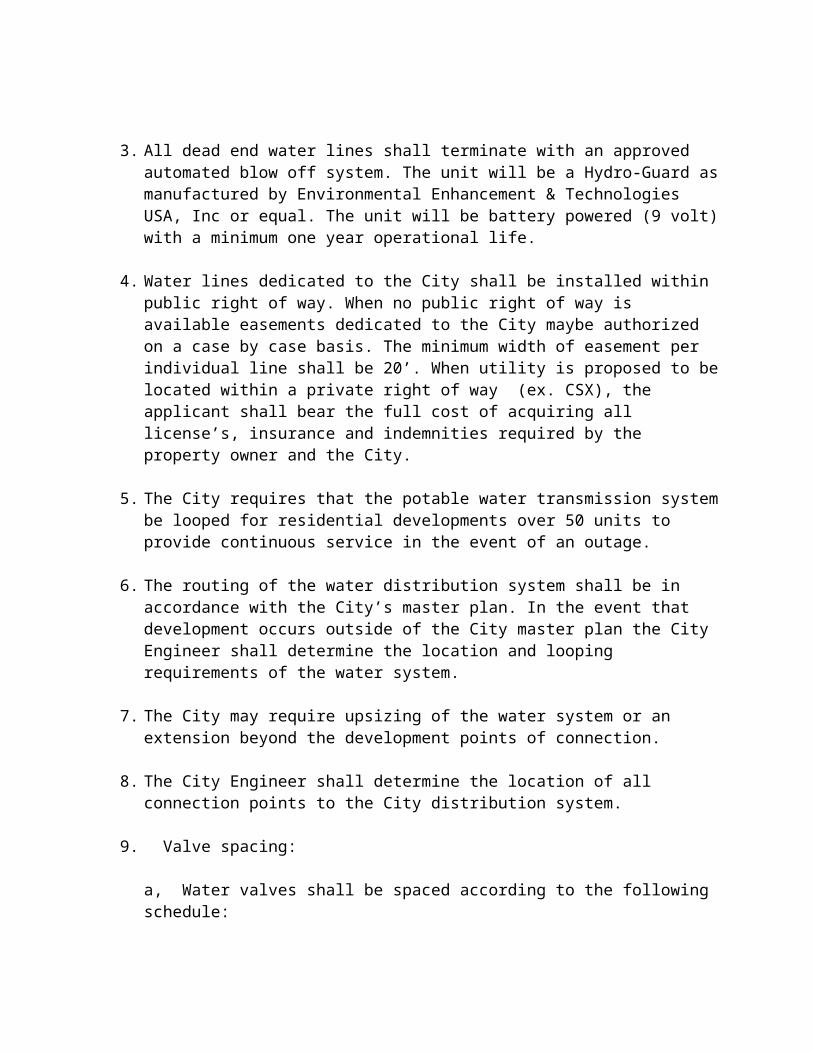
4. Hose Bibb connections shall be located in a locked below-grade vault clearly labeled “RECLAIM WATER” and bearing the words in English and Spanish “DO NOT DRINK, NO BEBER” together with an equivalent standard international symbol.
5. Rubber Hose Unit shall consist of a ¾ inch rubber hose with NY-Glass cam/groove ¾ inch coupling Part E and 1-1/4 inch stainless steel center punch clamps, designed
6. specifically for this Hose Bibb connection. On the other end of the hose shall be a ¾ inch brass male nipple to accommodate a standard spray nozzle or sprinkler attachment.
7. The Lock Box and Hose Bibb Assembly shall be located within the owner’s property boundary, visible from the street, and shall be located in the City right-of-way.
K) METERING REQUIREMENTS
1. Water meters shall be supplied by the City at the owners expense.
2. Meters may be delivered to the site for installation by the contractor. The City may if it elects to install the meter for individual customers.
3. PLACING METERS IN SERVICE
a. Inactive (newly installed) distribution lines: Once the distribution line has been flushed and the meter installation is complete, filling the main line and meter with reclaimed water shall be accomplished by slowly opening the inlet valve and allowing trapped air to be released slowly at the highest point available.
b. Active distribution lines: Once the meter installation is complete, slowly open the inlet valve in order to allow possible trapped air in the distribution system to be released at the highest point available.
WARNING: Avoid rapid expulsion of large slugs of entrained air because this could cause possible damage to the meters internal measuring mechanism.
L) GOLF COURSES AND OTHER MAJOR USERS
1. Golf courses and other major water users (over 100,000 gallons per day annual average) are required to install a meter and equipment to monitor and control the flow entering the property. Prior to the connection to the reclaimed water system, the golf course owner must enter into a service agreement with the City of Plant City. A copy of the standard golf course service agreement will be provided upon request.
2. The following is a general description of each of the required components. Specifications and detail exhibits may be obtained from the City of Plant City.
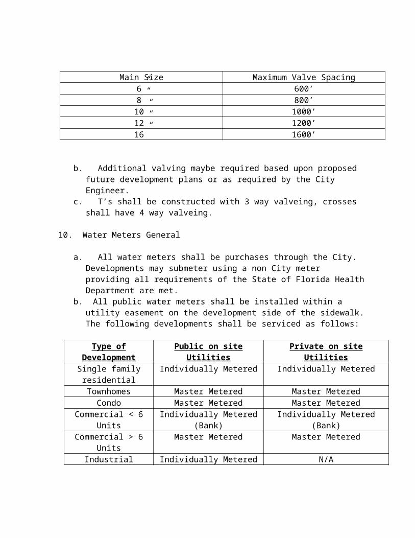
a. The meter shall be supplied by the City at the owners expense.
b. RECEIVING POND LEVEL SENSOR: The golf course owner is responsible for installing and maintaining, in good operating condition, one or more pond level sensors.The type of sensor shall be approved by the City.
c. CONTROL VALVE OPERATOR AND ELECTRONIC CONTROLLER: A control valve shall be installed at the metering and shall be configured to sustain upstream pressure and shall shut off when commanded from a remote location. In conjunction with an electric controller, the valve shall maintain a flow rate set point.
d. PRESSURE GAGES AND PRESSURE TRANSMITTER: Pressure gages shall be installed on the supply side distribution side of the metered connection.
e. REAL-TIME MONITORING AND CONTROL PANEL WITH PLC: The real-time monitoring and control field panel shall be installed at the metering station. The field panel shall contain all components necessary for both local and remote monitoring and control of the metering stations, including a programmable logic controller, (PLC) radio operator interface unit (OIU) electronic interface controller, open/close/remote hand switch, power supplies to control circuitry and surge suppression. Provide all programming necessary for operating system.
f. SPARE PARTS: Provide spare parts in accordance with the detailed specifications, prepared on a case-by-case basis for each metering station.
g. RADIO SURVEY: Conduct a radio survey for each site in which the City elects to communicate via a radio link. The objective is to demonstrate that radio signal strength is sufficient to support reliable communications. The radio survey shall consist of two parts – a radio propagation computer model and a field survey, where actual radios are used. The radio propagation computer model must include a path profile that clearly shows terrain and obstructions between both the remote and central sites.
h. POWER REQUIREMENTS: Provide all conduit and conductors as necessary for a complete operating system, including grounding, grounding systems inspection, and electrical testing.
M) CROSS-CONNECTION CONTROL
1. Backflow prevention is required in accordance with PL93-523, the Federal Safe Drinking Water Act, and subsequent amendments; and Florida Administrative Code (FAC) 62-555.360 for the protection of the potable water system.
2. At all locations where reclaimed water service is provided, the public potable water supply shall be protected by the installation of an approved backflow prevention device in accordance with Appendix B
3. No cross connection between the reclaimed water system and the potable water system shall be allowed.
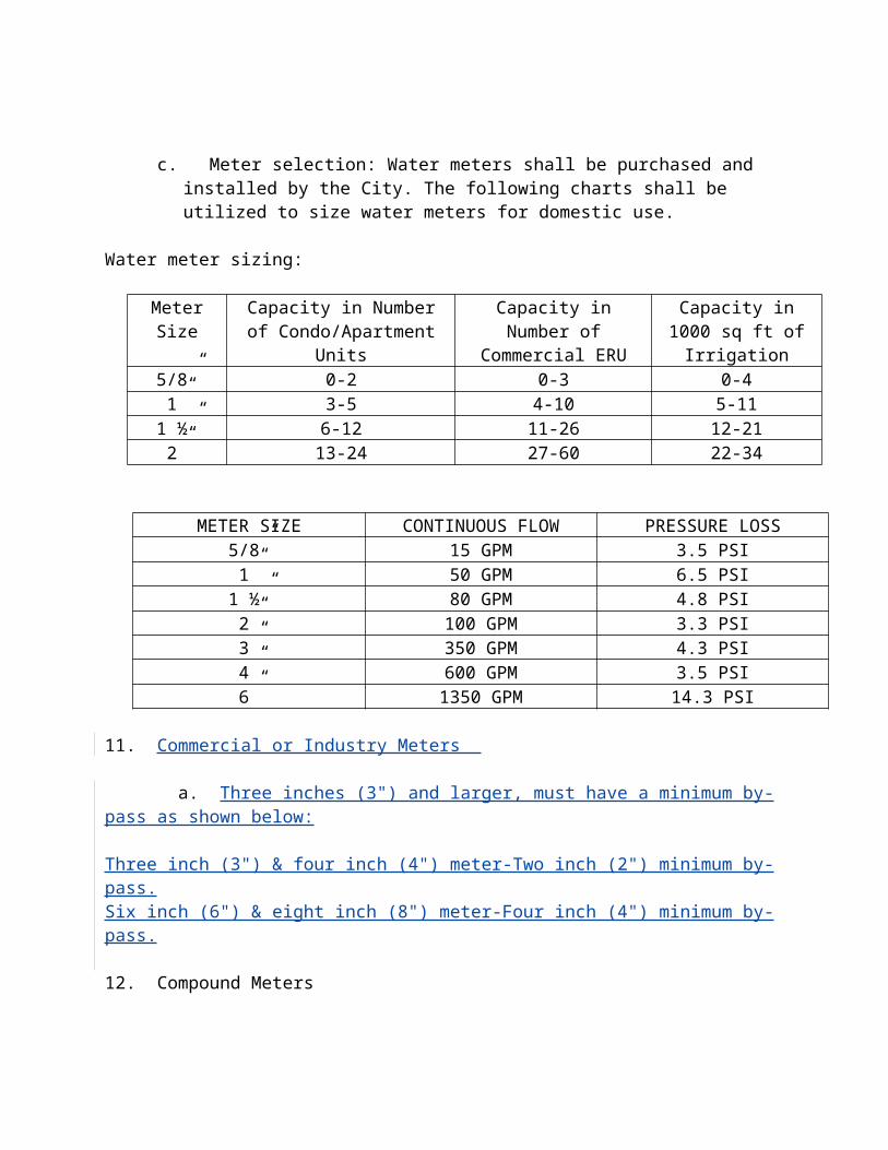
4. RESIDENTIAL CROSS-CONNECTION CONTROL
a. Prior to receiving reclaimed water service, the City of Plant City will install a dual check valve (a backflow prevention device) on each residential customer’s potable water meter in order to protect the potable water system.
b. Dual check valves shall be capable of being removed in line and shall comply with Appendix B.
5. MULTI-FAMILY AND COMMERCIAL PROPERTY CROSS-CONNECTION CONTROL
a. Multi-family complexes and commercial properties with master-metered potable water service and master-metered reclaim water service shall be required to install a Reduced Pressure Principal type backflow prevention device downstream of the master potable water meter.
b. The Reduced Pressure Principal type backflow prevention assembly shall include two independently acting check valves; a hydraulically operating, mechanically independent pressure differential relief valve located both between the check valves and below the first check valve, properly located resilient-seated test cocks, and tightly closing resilient-seated shut-off valves attached at each end of the assembly. Shut-off valves 2-inches and smaller shall be ball type; valves larger than 2 inch shall be gate type.
N) SYSTEM IDENTIFICATION AND SIGNAGE
1. All reclaimed water piping and appurtenances shall be clearly identified as reclaimed water facilities.
2. The standard color is Pantone Purple 522C for all reclaimed water system piping and above ground appurtenances including valves, meter assemblies, and backflow prevention devices.
3. PVC distribution mains the Pantone Purple color shall be an integral part of the pipe materials.
4. Ductile iron distribution mains shall be color coded with purple stripes or tape with adhesive backing. Adhesive tape shall be vinyl at least 5 mils thick and at least 2 inches wide. Above ground piping shall be painted Pantone Purple 522C. Marking shall run parallel to the axis to the pipe and a continuous stripe along the top is required.
5. Polyethylene (PE) service pipe or tubing shall be the standard purple or identified with a purple stripe with the words “RECLAIMED WATER” at 8 inch intervals.
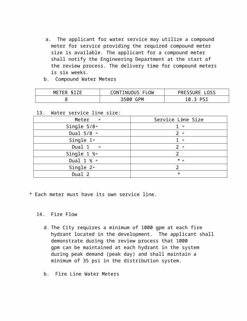
6. Valves installed below ground shall be identified with a stainless steel tag and purple curb markers to differentiate reclaimed water valves from potable water valves.
7. Covers for all valves boxes, meter and service boxes, and other below-ground devices on the reclaimed water system shall be painted purple as indicated in this section and shall be permanently embossed “RECLAIMED WATER” and bear the words in English and Spanish “DO NOT DRINK, NO BEBER,” together with the equivalent standard international symbol.
8. Electronically detectable tape shall be installed in trenches above all PVC reclaimed water piping approximately 18 inches above the pipe. Tape shall be a minimum of 4.5 mils thick and a minimum of 2 inches wide, with aluminum core covered by a purple polyethylene coating with the words “CAUTION RECLAIMED WATER LINE BELOW.”
9. All non-metallic pipes shall be installed with 2 insulated 10 gauge copper locating wires attached at 10:00 and 2:00. Wires shall be attached using minimum 2 inch wide duct tape. Tape shall be at every joint and have 4 to 5 feet spacing. Locating wires shall terminate 4 or more inches above the concrete valve pad and fold back inside a 3 inch PVC access pipe.
10. The public shall be notified of the use of reclaimed water by posting advisory signs designating the nature of the reuse project area where reuse is practiced.
11. Signage shall be placed as appropriate at entrances to residential neighborhoods where
reclaimed water is used for landscape irrigation and at prominent locations at all commercial sites, including multi-family developments, office parks, schools, churches, condominiums, residential common areas, recreational developments and golf courses.
12. Advisory signs shall be posted adjacent to lakes or ponds used to store reclaimed water and at decorative water features that use reclaimed water. Advisory shall include the following text in English and Spanish “DO NOT DRINK, NO BEBER” and “DO NOT SWIM, NO NADIR,” together with the equivalent standard international symbols, in addition to “RECLAIMED WATER”.
13. Tags or labels for all reclaimed water valves and outlets shall be provided, bearing the words in English and Spanish: “DO NOT DRINK, NO BEBER” together with the equivalent standard international symbol. Curb markers shall be used when appropriate.
O) TRENCH EXCAVATION, PIPE CUTTING AND LAYING, AND BACKFILLING
Trenching, excavation, cutting, laying, and backfilling shall be performed in accordance with the potable water requirements listed in this manual.
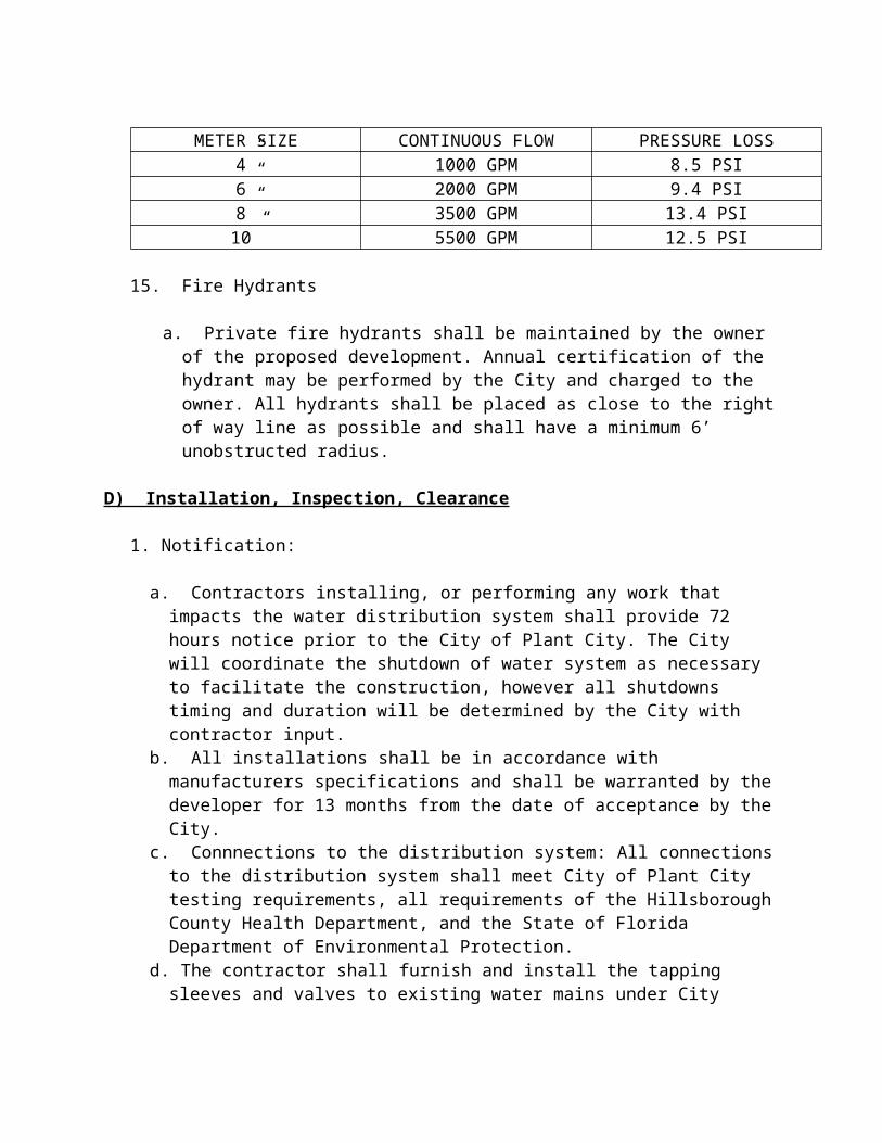
Testing of the reclaim water system shall be performed in accordance with the requirements of the potable water system listed in this manual. No chlorination is required.
Chapter 13
Sanitary Sewer System
A) DETAILS OF DESIGN AND CONSTRUCTION
1. No public gravity sewer conveying raw wastewater shall be less than 8 inches in diameter.
2. All sanitary sewers and forcemains shall be installed with a minimum of 36 inches of cover.
3. All sewers shall be designed and constructed to give mean velocities, when flowing full, of not less than 2.0 feet per second, based on Manning’s formula using and “n” value of 0.013. The following are the recommended minimum slopes which should be provided; however, slopes greater than these are desirable.
Minimum Slope in FeetNominal Sewer Size Per 100 Feet
8 inch 0.40
10 inch 0.28
12 inch 0.22
14 inch 0.17
15 inch 0.15
16 inch 0.14
18 inch 0.12
21 inch 0.10
24 inch 0.08
27 inch 0.067
30 inch 0.058
33 inch 0.052
36 inch 0.046
39 inch 0.041
42 inch 0.037
4. Slopes slightly less than those recommended for the 2.0 feet per second velocity, when flowing full, may be permitted. Such decreased slopes may be considered where the depth of flow will be 0.3 of the diameter or greater for design average flow.
5. The pipe diameter and slope shall be selected to obtain the greatest practical velocities to minimize settling problems. Oversize sewers will not be approved to justify using flatter slopes. If the proposed slope is less than the minimum slope of the smallest pipe which can accommodate the design peak hourly flow, the actual depths and velocities at minimum, average, and design maximum day and peak hourly flow for each design section of the sewer shall be calculated by the design engineer and be included with the plans.
6. Sewers shall be laid with uniform slope between manholes. Straight alignment shall be checked by either using a laser beam or lamping.
7. Where velocities greater than 15 feet per second are attained, special provision shall be made to protect against displacement by erosion and impact.
8. Sewers on 20 percent slopes or greater shall be anchored securely with concrete, or equal, anchors spaced as follows:
a. Not over 36 feet center to center on grades 20 percent and up to 35 percent;b. Not over 24 feet center to center on grades 35 percent and up to 50 percent; c. Not over 16 feet center to center on grades 50 percent and over.
9. When a smaller sewer joins a large one, the invert of the larger sewer should be lowered sufficiently to maintain the same energy gradient. An approximate method for securing these results is to place the 0.8 depth point of both sewers at the same elevation.
10. Sanitary sewer systems shall be designed by a professional engineer licensed by the State of Florida. The piping systems and all component parts shall be complete, comply with the provisions of the specifications and all engineering drawings, and must receive the final approval of the Engineer; and furnished and installed in accordance with the rules, regulations, and requirements of the following:
Applicable Federal Specifications
American Standards AssociationAmerican Waterworks AssociationFlorida Department of Environmental Protection
11. The contractor shall be a licensed underground utility contractor.
12. The minimum forcemain size shall be 6 inches, however 4-inch forcemains will be considered on a case by case basis if the the forcemain length is less than 1000 feet and flow is less than 120 gpm peak flow. If a 4 inch force main is allowed pumps will be designed to deliver the peak flow or 100 gpm whichever is greater in order to maintain 2.5 fps velocity. If pump selected is 3 hp, a 4 ft diameter wet well will be used in lieu of the 6’ minimum size.
13. Forcemains shall be designed to meet the minimum cleansing velocity of 2.5 fps with a maximum pressure of 25 psi in the forcemain.
14. All publicly owned lift stations shall use the pumps and corresponding pump curves listed in Appendix XXXXX.
15. In some cases the installation may not see maximum flows for an undetermined time period. As such, in cases where the anticipated peak flow will not be achieved within 6 months the applicant will provide multiple impellers to maximize the efficiency of pump station operation.
B) MANHOLES
1. Manholes shall be installed at the end of each line; at all changes in grade, size, or alignment; at all intersections; and at distances not greater than 400 feet for sewers 15 inches or less, and 500 feet for sewers 18 inches to 30 inches, except that distances up to 600 feet may be approved in cases where adequate modern cleaning equipment for such spacing is provided. Greater spacing may be permitted in larger sewers. Cleanouts may be used only for special conditions and shall not be substituted for manholes nor installed at the end of laterals greater than 150 feet in length.
a. Precast Concrete Manholes: Manholes shall meet the requirements of ASTM C478 with the exceptions specified herein. Cement shall meet the requirements of ASTH C150, Type II. Reinforcing steel shall be as shown on the standard manhole detail. Concrete shall meet the minimum requirements for Class "A", 4000 psi. Minimum wall thickness shall be 8 inches. The required minimum strength of concrete shall be confirmed by making and testing three standard cylinders at seven days. An integrated neoprene boot shall be incorporated into the manhole to meet indicated pipe alignment conditions and invert elevations. Neoprene boot shall be A-lok or Z-lok or equal. Submit shop drawings, consisting of manufacturer's standard details of various
sections, for approval before placing order for manholes. Drawings of individual manholes showing invert elevations, pipe sizes and required construction details shall be submitted.
b. Joints: Form joint contact surfaces with machined castings. Surfaces shall be exactly parallel with nominal 1/16-inch clearance and the tongue equipped with a proper recess for the installation of an 0-ring rubber gasket. Gaskets shall meet the requirements of Specification for Joints for Circular Concrete Sewer and Culvert Pipe, using Rubber Gaskets. "RAM-NEK" sealing compound, conforming to Federal Specification SS S-00210A, may be used in lieu of 0-ring rubber gaskets. If joints are sealed with "RAM-NEK" sealing compound, the recess in the tongue for an 0-ring gasket may be omitted.
c. Manhole Frames and Lids: Shall conform to ASTM A48, Class 30, or Grade 60-45-10 ductile iron, meeting the requirements of ASTM A536, cast in a true symmetrical pattern of tough, dense and even-grained iron, free from warping, scales, lumps, blisters, sandholes or any defects of any kind. Provide "0" ring seals at touching
surfaces to provide firm seats and prevent rocking. Remove and replace any set not matching perfectly.
d. Frames and lids shall be designed to withstand an HS20-44 traffic loading as defined in AASHTO Specifications. Minimum weight, 285 pounds total. Lids shall bear the name "City of Plant City" along the top with "Sanitary" in the center of the lid and the date along the bottom. Approved: U.S. Foundry No. 170E with "O" ring seal, or equal.
e. Precast Concrete Manhole Installation: Set precast concrete sections vertical and in true alignment. Install 0-ring rubber gasket in the recess in the base of previously set section or prime and double seal joint surfaces with "RAM-NEK', or equal, premolded plastic joint sealer or equal.
f. Grouting: Completely plug seal and smooth all holes in sections used for their handling and the annular space between the wall and entering pipes with nonmetallic, nonshrink grout such as Saureisen F-100, or equal. Finish grout smooth and flush with the adjoining interior and exterior manhole wall surfaces and make watertight.
g. Setting Manhole Frames: Set manhole frames and lids flush with finish pavement or 0.1 foot above the finished grade unless shown or directed otherwise by the Engineer. Set frames on manholes concentric with the masonry and in a full bed of mortar so that the space between the top of the manhole masonry and the bottom flanges of the frame will be completely filled and made watertight. Place a ring of mortar around the outside of the bottom flange at least 1 inch thick and pitched to shed water away from the frame. Extend mortar to the outer edge of the masonry and finish smooth and flush with the top of the flange.
2. Drop Type
a. A drop pipe shall be provided for a sewer entering a manhole at an elevation of 24 inches or more above the manhole invert. Where the difference in elevation between the incoming sewer and the manhole invert is less than 24 inches, the invert shall be filleted to prevent solids deposition.
b. Drop manholes should be constructed with an outside drop connection. Inside drop connections (when necessary) shall be secured to the interior wall of the manhole and provide access for cleaning.
c. Due to the unequal earth pressures that would result from the backfilling operation in the vicinity of the manhole, the entire outside drop connection shall be encased in concrete.
3. Diameter
a. The minimum diameter of manholes shall be 48 inches; larger diameters are preferable for large diameter sewers. A minimum access diameter of 22 inches shall be provided.
4. Flow Channel
a. When curved flow channels are specified in manholes, including branch inlets, minimum slopes indicated in paragraph A.8 should be increased to maintain acceptable velocities.
b. The minimum acceptable drop across the manhole shall be .1 inch.c. Inverts: Form manhole invert-channels of cut pipe or mortar and brick to provide a
smooth-flowing self-cleaning channel of the shape and size of the sewers to which it connects.
d. Straight Run Manholes: Shape inverts while manholes are under construction. Lay pipe continuously through manhole, build invert, cut or break out pipe above mid-point and smooth broken edges with cement mortar. Straight run manholes shall be no further than 400 feet apart.
e. Junction Manholes: Shape inverts while manholes are under construction. Lay pipe continuously through manhole, build invert, break out pipe above mid-point and smooth broken edges with cement mortar or cut off pipe at inside faces of manhole and construct invert to exact shape and size of pipe indicated. Construct smooth inverts following grades of pipes leaving manholes. Provide a true curve of the largest radius possible for changes in direction of sewer and entering branch or branches.(No dog house manholes permitted)
5. Bench
a. A bench shall be provided on each side of any manhole channel when the pipe diameter(s) are less than the manhole diameter. The bench should be sloped no less than ½ inch per foot (4 percent). No lateral sewer, service connection, or drop manhole pipe shall discharge onto the surface of the bench.
6. Watertightness
a. Manholes shall be of the pre-cast concrete or poured-in-place concrete type. Manhole lift holes and grade adjustment rings shall be sealed with non-shrinking mortar or other material approved by the regulatory agency.
b. Inlet and outlet pipes shall be joined to the manhole with a gasketed flexible watertight connection or any watertight connection arrangement that allows differential settlement of the pipe and manhole wall to take place.
c. Watertight manhole covers are to be used wherever the manhole tops may be flooded by street runoff or high water. Locked manhole covers may be desirable in isolated easement locations or where vandalism may be a problem.
7. Inspection and Testing
a. The specifications shall include a requirement for inspection and testing for watertightness or damage prior to placing into service. Air testing, if specified for concrete sewer manholes, shall conform to the test procedures described in ASTM C-1244.
8. Corrosion Protection For Manholes
a. Where corrosive conditions due to septicity or other causes is anticipated, the City may require the installation of an “HDPE” or “PFE” type liner.
b. All manholes that receive flow from pressure forcemains shall have the receiving manhole lined with a “HDPE” or “PFE” type liner. Additional manholes may be lined as required by the City Engineer.
9. Manhole grade adjustment shall be made with brick conforming to ASTM C32, Grade MS, and shall be sound, hard and uniformly burned, regular and uniform in shape and size, with compact texture. Brick shall be used for manhole grade adjustments but not for construction.
Portland Cement: Shall conform to ASTM C150, Type II. Approved:Atlas; Florida; Lehigh; or equal.
Sand: Washed silica sand shall conform to ASTM C144.
Mortar: Consists of one part cement and two parts sand.
a. Brickwork: Wet brick before laying. Set true to line with courses plumb. Use no mortar that has begun to set. Lay bricks radially as headers with every sixth course laid as stretchers. The sides of each brick shall be buttered and shoved (not laid) in a full bed of mortar. Horizontal joints shall not be greater than 1/2-inch thick. Fill
longitudinal and transverse joints completely in each course before starting the next course. Joints shall be struck flush and the interior and exterior of the manhole plastered with 1/2-inch thick coat of mortar to leave a dense, smooth finish, so that the manhole shall be watertight.
C) Pipe
1. Ductile Iron
a. Ductile iron pipe shall be designed in accordance with the latest revision of ANSI/AWWA C150/A21.50 for a minimum 150 psi (or project requirements, whichever is greater) rated working pressure plus a 100 psi minimum surge allowance; a 2 to 1 factor of safety on the sum of working pressure plus surge pressure; Type II laying condition and a depth of cover of 2.5 feet minimum.b. Ductile iron pipe shall be manufactured in the U.S.A. in accordance with the latest
revision of ANSI/AWWA C151/A21.51. Each pipe shall be subjected to a hydrostatic pressure test of at least 500 psi at the point of manufacture.
c. Pipe shall have standard asphaltic coating on the exterior. Pipe shall also have a cement mortar lining on the interior in accordance with ANSI/AWWA C104/A21.4, of latest revision.
d. The class or nominal thickness, net weight without lining, and casting period shall be clearly marked on each length of pipe. Additionally, the manufacturer's mark, country where cast, year in which the pipe was produced, and the letters "DI" or "Ductile" shall be cast or stamped on the pipe.
e. All pipe shall be furnished with Push-on Type Joints, such as "Tyton" or "Fastite". Joints shall be in accordance with ANSI/AWWA C111/A21.11, of latest revision, and be furnished complete with all necessary accessories.
f. Fittings shall be manufactured in the U.S.A. and be either ductile iron or gray iron. Ductile iron fittings shall conform to the latest revisions of either ANSI/AWWA C110/A21.10 or ANSI/AWWA C153/A21.5. Gray iron fittings shall be in accordance with ANSI/AWWA C110/A21.10, of latest revision. Fittings shall have a standard asphaltic coating on the exterior. Fittings shall also have a cement mortar lining on the interior in accordance with ANSI/AWWA C104/A21.4, of latest revision.
g. Fittings and accessories shall be furnished with either Mechanical or Push-On Type Joints in accordance with ANSI/AWWA C111/A21.11, of latest revision.
h. All pipe, fittings, and accessories shall be installed and tested in accordance with the latest revision of AWWA Standard C600. Newly installed ductile iron sewer mains shall be disinfected in accordance with the latest revisions of AWWA Standard C651 prior to placing in service.
2. Polyvinyl Chloride (PVC) 4" - 12":
a. Manufacture in accordance with ASTM D3034, Type PSMa, maximum SDR 26 (extra strength), long term deflection shall not exceed 5%.
b. Joints: Bell and spigot type with rubber sealing ring in accordance with ASTM D3212. The bell shall consist of an integral wall section with a solid cross section rubber ring factory-assembled.
c. Fittings: Fittings and accessories shall be as manufactured and furnished by the pipe supplier or approved equal and shall have bell and/or spigot configurations identical to that of the pipe. Fittings shall be as specified in ASTM 3034 for use with SDR 26, extra strength type PSM PVC Pipe, with bell and spigot joints as specified in ASTM 3212.
3. Pipe Installation: Install all pipework meeting the requirements of ASTM D2321 to the extent that they apply and as specified hereinafter for the various types and classes of pipe.
Lay all gravity sewers in the following manner after cut sheet has been approved and signed by the Engineer. Tightly stretch a mason's line above the sewer trench parallel to the axis of the sewer. Support adequately at intervals not exceeding 25 feet, except where the pipe gradient exceeds 1.0 percent, the intervals may be lengthened to 50 feet. A laser beam may be substituted for the above specified mason's line provided the Contractor furnishes full information on the equipment to be used and the procedure to be followed and approval is obtained from the Engineer prior to the laying of pipe. Obtain exact grade and alignment for each pipe by measuring and plumbing down from this line to the invert of the pipe. Lay pipe upgrade, beginning at the lower end of the sewer, with pipe bell ends up-grade. Exercise extreme care to keep the pipe in exact alignment and elevation. It is the Contractor's responsibility to make exploratory excavations and/or use other methods available to locate existing utilities prior to construction of any gravity sewers. If necessary, the Contractor shall adjust the new sewers and/or laterals, subject to approval by the Engineer, to avoid conflicts with existing piping. Install pipe joints on each line entering or leaving manhole, including stub lines, as close to manhole exterior wall as practical. In all cases, joints shall be within the limits of poured-in-place bases. In no
case shall the pipe be walked on either before or after the joints have been made. Securely close all openings such as stubs, wyes or other services along the lines by means of approved stoppers that fit into the bells of the pipe and are recommended by the pipe manufacturer. Install stoppers in such a manner that they may be removed at some future time without injury to the pipe bells. No bricking or grouting plugs in lines will be permitted.
4. Laying Pipe: Take all necessary precautions to prevent the entrance of mud, sand or other obstructing matter into the pipelines. Lay pipe on bedding prepared in accordance with ASTM D1557 and a minimum of 90 percent density bedding for the pipe installed, in accordance with the plans and Earthwork section of these specifications; provide uniform bearing under the full length of the pipe barrel. Excavate for pipe bells and carefully lay pipe true to line and grade. Make adjustments to line and grade by scraping away or filling
a
in and tamping under pipe barrel and not by wedging or blocking up any portion of the pipe. Abut the spigot end of each pipe against base of socket of adjacent pipe in such a manner that there will be no unevenness of any kind along the bottom halves of the pipes. Compact sufficient backfill, immediately after the pipe has been jointed and inspected, to protect the pipe adequately from injury and movement. At the close of each day's work, and at other times when pipe is not being laid, protect the end of the pipe with a close-fitting stopper approved by the Engineer. Replace with sound pipe, any defective pipe which may have been laid. Upon completion, installed pipe lines shall show a full circle of light when lamped between manholes.
5. Stub Lines: Provide plugged stub lines where shown or directed by the Engineer for the connection of future sewer lines to manholes. Provide bell end closed with an approved stopper at the end of each stub line. Install bell of stub line as close to manhole exterior surface as practical.
D) Joints
1. Mechanical: Shall conform to ANSI A21.11/AWWA C111, rubber gasket joints for cast iron and ductile iron pressure pipe and fittings.
2. Push-on: Shall conform to ANSI A21.11/AWWA C111, rubber gasket joints for cast iron and ductile iron pressure pipe and fittings. Single gasket push-on type.
3. Flanged: ANSI Standard Specifications 21.15 - Latest Revision, American National Standard for Flanged Ductile Iron Pipe with Threaded Flanges. Screwed-on flanges, faced and drilled to ANSI Class 125 pound template. Provide one-eighth inch (1/8") gaskets. Rubber gasket shall be Toruseal as manufactured by American Cast Iron Pipe Company or equal. Flanged pipe minimum thickness shall be class 53. Per AWWA C115 A21.15-88.
4. Harnessed or Restrained Pipe: Provide at all fitting restrained joints where unbalanced reactions occur unless otherwise approved. Fittings shall be restrained to a sufficient length of straight pipe to resist the thrust generated by an internal water pressure of 150 psi. Determine the length of harnessed or restrained joints actually required by the Thrust Restraint Design for Ductile Iron Pipe, Third Edition 1992 as developed by Ductile Iron Pipe Research Association. Submit for approval calculations for the determination of the length of harnessed or restrained pipe at each of the various type of fittings to be installed. Restrained joints shall be Mega Lug or approved equal.
5. Joint Schedule - Ductile Iron:
Flange: Use above ground on in vaults.
Mechanical or Push-on: Use on buried pipe only.
E) Lining and Coating
1. Exterior Pipe Coating: Shall be bituminous or asphalt, meeting they requirements of the pipe manufacturer and ANSI A21.10/AWWA C110.
2. Polyethylene lining: Conforming to ASTM D1248, factory applied and fused and bonded to the pipe. Minimum thickness shall be 40 mil throughout the pipe. Injurious mechanical damage such as chuck marks and gouges extended to bare metal are not acceptable. Each pipe shall be inspected for proper lining thickness by the manufacturer;
Manufacturer's Testing Laboratory to certify that lined pipe furnished is free of any pin-holes and/or holidays. Provide Manufacturer's Testing Laboratory's certification that a witnessed Adhesion Test was performed on one pipe of each size per shift lined for this
project. At the discretion of the Engineer, pipe having such defects shall be rejected. The only acceptable method of factory or field repair is to trim off the loose ends of the polyethylene, thoroughly dry and clean the bare metal by sanding or wirebrushing, and applying a multi-coat, multi-pass application of an approved coal tar epoxy paint system as specified below.
3. Manhole Interior and Exterior Coatings: For the purpose of establishing a quality standard, the material listed below is manufactured by the Koppers Company. The coating shall take place on or near the site, so as to minimize movement of the manhole sections prior to installation. After installation, the contractor shall prepare the surfaces around the joints for additional application of the coating to complete the coverage of the entire exterior surface. All applications shall comply with the following coating schedule:
All coats shall be applied with airless sprayer so as to completely stain all surfaces and penetrate the mortar or concrete. If additional coat(s) are not applied within 24 hours, the area to be recoated shall be either roughened by a brush-blast or pretreated with Bitumastic 2 CB before recoating
F) Service Laterals
1. Polyvinyl Chloride (PVC): Pipe, joints and fittings shall conform to ASTM D3034, Type PSM with a maximum SDR of 26, long term deflection shall not exceed 5%.
Coating Dry FilmSystem Type Coat No. Coating Thickness (Min.)Coal Tar Epoxy
1 Bitumastic No. 300-H reduced 2:1 with Thinner 2000
2 Bitumastic No. 300-M 10 mils3 Bitumastic No. 300-M 10 mils
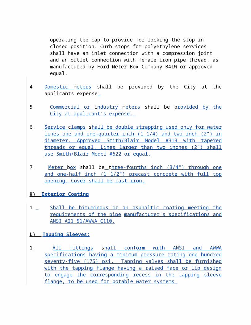
2. Prefabricated polyvinyl joint sealer adapters and sewer pipe couplings shall be similar to those manufactured by Fernco Joint Sealer Company, pipe manufacturer, or equal. Flexible couplings shall be installed with stainless steel bands and adjusting screws.
3. Service Connections:
a. General: Install types of connections generally as shown, directed by the Engineer, or as necessary to maintain existing sanitary sewer service. Service connections shall be made to 8-inch highline or nearest manhole with approval of the City Engineer. Each service connection shall be accurately recorded by reference to the center of the downstream manhole.
b. Marking Service Lines: A cleanout shall be placed at the end of each service pipe and located near the right-of-way line, unless shown or required otherwise. The curbing shall be marked by cutting a "S" for single lateral or "$" for double services. See Electronic Marker Systems.
c. Service Assembly: Provide a wye or tee branch, 6-inch curves and fittings concrete as shown on the drawings, and specified herein. If the service line is not installed at the time of construction, the opening shall be securely closed with approved stopper(s) specified herein before in paragraph "Pipe Installation".
d. Service Pipe: Where directed by the Engineer, install 6-inch and 4-inch PVC service pipe and any fittings required from each main-tee service connection to the property line and connected or plugged at the right-of-way line. The adapter for connection-transition from PVC to vitrified clay/ductile iron house service pipe shall be a “fernco” type fitting. If vitrified clay pipe with factory-molded joint is used for connection to adapter, the joint material shall be compatible with the pipe adapter. The openings at the ends of all house service pipes that are not connected to house sewers shall be securely closed with approved stoppers as specified hereinbefore in paragraph "Pipe Installation".
e. Electronic Marker System: All installed service laterals shall be marked by a 4" electronic ball marker system. The ball shall be placed over the services at the property line. The ball marker shall not be placed any deeper than 3 feet below finished grade. The ball will be green in color and made of high-density polyethyiene. Ball marker shall be "Scotch Mark" Manufacture by 3M or approved equal.
G) Tests
General: Contractor shall inspect all work constructed for faults or defects and any such deviation from these documents or omissions shall be corrected at once. All tests shall be made by the Contractor, who shall provide necessary equipment for and lamping the system in the presence of the Engineer. All costs for these tests and inspections shall be borne by the Contractor.
Infiltration: After completion, the sewers or sections thereof shall be tested for
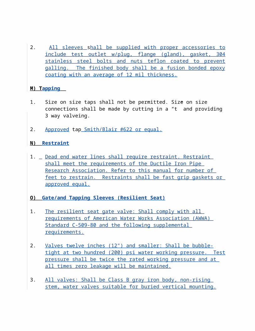
infiltration. Any infiltration will not be accepted and shall be corrected immediately.
1. At the end of the 1 year warranty period the line may be required to be retested at which time there is an allowance of 50 gallons per mile per inch in diameter of sewer pipe per day. Any amount above this will be rejected until corrective work has been performed to bring it within the allowable limit. The allowable infiltration for any one trunk, main, lateral or segment between manholes shall be in accordance with the appropriate requirements.
Exfiltration: Tests for exfiltration may be required by the Engineer. Exfiltration shall be in accordance with the requirements of ASTM requirements as modified by the Engineer. An allowance of 10 percent of exfiltration gallonage shall be permitted for each additional two foot head over the basic top-of-manhole head.
Low Pressure Air Testing: After completion, each section of pipe between manholes shall be tested using low pressure air, in accordance with UNI B6. Allowable pressure drop shall be as given in UNI B6. Make calculations in accordance with the Appendix to UNI B67.
Methods: Measurements and tests of infiltration will be made as soon as possible after construction of sufficient lines to warrant a test. All measurements shall be made by means of a weir suitable for this purpose, or by actual volumetric measuring, direct from or to the sewer. All lines which contain accessible infiltration as determined by the Engineer shall be repaired and retested as necessary, until test requirements are met. The Engineer reserves the right to require the Contractor to test each section between manholes laid by each pipe crew under this contract.
2. Alignment:
Lines shall show full circle of light when lamped between manholes for line sections with complete pipe replacement. Televise the lamping.
A nine-point mandrel shall be passed through each new PVC and/or flexible pipe section installed no sooner than 30 days after final backfill has been placed. The maximum pipe diameter deflection shall not exceed 5 percent.
3. Warranty Test:
To insure the adequacy of the above described pipe and manhole installation procedures, the Contractor shall remobilize to the work site ten (10) months following final approval-acceptance of the complete project, such time being within the one (1) year warranty period, as stated in the General Conditions. The date for such remobilization will be stated in the Final Approval issued by the Engineer.
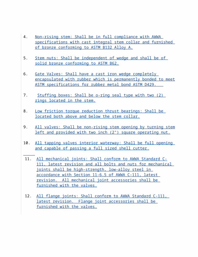
The Contractor, together with representatives of the Engineer and the Owner, shall visually inspect every manhole and new line sections installed within the project area for cracks, damaged lining, leaks or abnormal conditions. The line sections will be chosen by the Engineer/Owner at random, subsequent to the manhole inspections.
Any deficiencies which are found by such visual inspection shall have appropriate corrections made by the Contractor, as approved by the Engineer. To adequately locate certain deficiencies, the Contractor may be required to use other testing methods, including flow isolation closed circuit television inspection, and others.
All costs involved in remobilizing, inspection or correction of deficiencies will be considered incidental to the project and shall be the responsibility of the Contractor at no additional cost to the owner.
4. Television Inspection of Sanitary Sewer:
Scope of Work: The work includes the final visual inspection with audio description and recordings in approved logs of the finished gravity sewer installation or portion thereof. After completion of the Contract, the Contractor shall furnish to the Engineer a complete bound report of the television inspection logging each section of sewer televised and giving specific details as to service connections.
5. Photographs taken at the direction of the Engineer during the course of the work shall be neatly mounted within this report. A copy of the form to be used shall be submitted to the Engineer for approval prior to work. The video tapes shall become the property of the Owner upon completion of work. The video tapes shall be edited as stated in the Special Conditions.
Measurements: Televising equipment shall be outfitted with a measuring device so that it is clearly visible during the entire video taping. The measuring device shall be fastened so the zero mark touches the bottom center point of pipe and is distant enough from the camera to not hinder the picture. The device shall have a range of 0-4" with increments of not more than 1/8". All findings of any deficiencies shall be recorded in the Television Logs. Deficiencies shall be repaired as directed by the City engineer or designee.
6. Equipment:
Quality: All equipment used for televising sewer lines shall be of the highest quality and shall have high performance capabilities. It shall be manufactured by a company engaged in the research, development and manufacturing of said equipment.
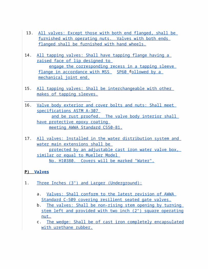
Television System: The television system shall be color self contained system complete with winches, (power and mechanical), 1,000 feet minimum cable, closed circuit television camera, monitor, video tape recorder, photograph camera, film, suitable measuring device accurate to within 1.0 foot within 500 feet, to determine the position of the camera in the line being televised at all times, and all necessary equipment for the successful completion of television inspection. The television system shall have the ability to superimpose the measured footage onto the monitor screen and be recorded visually by the video tape recorder. All equipment shall be approved by the Engineer.
Camera: The television camera used for the inspection shall be one specifically designed and constructed for such inspection. Lighting for the camera shall be suitable to allow a clear picture for the entire periphery of the pipe. The camera shall be operative in 100% humidity conditions. The camera, television monitor and other components of the video system shall be capable of producing a minimum 500 line resolution video picture. Picture quality and definition shall be to the satisfaction of the Engineer and if unsatisfactory, equipment shall be removed and no payment made for unsatisfactory inspection. Whenever non-remote powered and controlled winches are used to pull the television camera through the line, telephones or other suitable means of communication shall be set up between the two manholes of the section being inspected to insure good communications between members of the crew.
7. Execution:
Scope of Purpose: It is the intent of this section to provide a basis by which the sanitary sewer lines installed in this project can be internally inspected by means of a closed circuit television camera and a permanent record made of the findings. The Contractor shall notify the Engineer 24 hours in advance of televising any line section.
8. Methodology:
The Contractor shall furnish all labor, electronic equipment and technicians necessary to perform the closed circuit television inspection of the sewers.
Operation of the equipment shall be controlled by a skilled technician with a minimum of two years experience in television inspection from a control panel in a television studio. The television studio shall be large enough to accommodate three people for the purpose of viewing a monitor while the inspection is in progress.
The Engineer and Owner shall have access to view the television screen at all times. The view seen by the television camera shall be transmitted to a monitor approved by the Engineer.
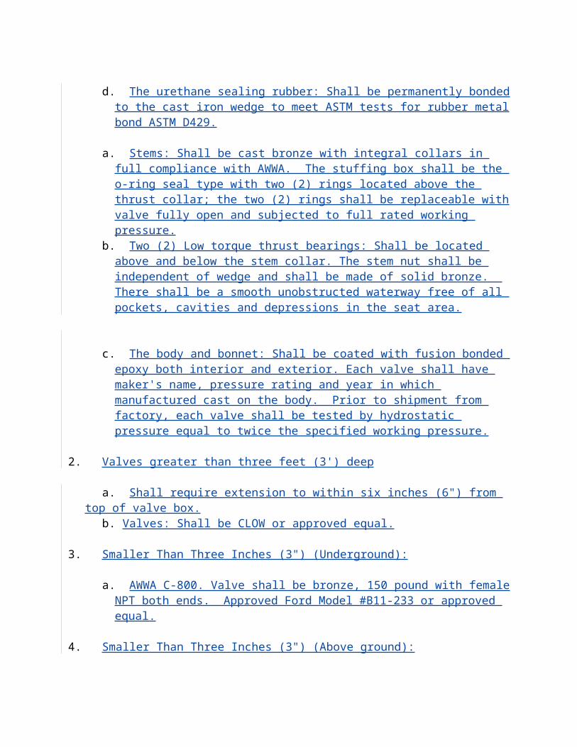
The technician shall have the capability of controlling the movement of the television camera, adjusting the brilliance of the built-in lighting system and changing the focus of the television camera by remote control.
The sewer lines shall be internally cleaned prior to televising as previously specified. Any debris, grease or other material causing a blocking of the lens preventing proper viewing of the sewer shall be removed.
After thoroughly cleaning the sewer and just prior to televising, there shall be a 100 gallon flush of clean water introduced to the up stream manhole. Time will be allowed for the water to stop flowing before televising begins.
The camera shall be turned on and a slow, visual inspection shall be made of the manhole corbel, walls and pipe connections, with proper audio identification of conditions, defects and orientation. The camera shall be placed in the manhole invert of the line section to be inspected and slowly positioned to a spot no greater than six (6) feet from the start of pipe so as to position the cable roller assemblies. The point of reference for all distance measurements shall be a specific object within one to two feet in front of the camera lens, said object to be mutually agreed upon between the Contractor and the Engineer. The footage indicator will be set at zero for the center of the staring manhole and shall record the camera's position to the aforementioned object within the pipe. This initial operation shall be continuously recorded by the camera and all findings recorded in the log. At the ending manhole, the camera shall continue to record the pipe and manhole condition as in the starting manhole. The footage measurement shall end when the center of ending line manhole is reached. Any horizontal differences along the section between the center of the manhole frame and the center of the manhole base for either manhole shall be measured and recorded.
The television camera shall be pulled through the sewer lines by use of a mechanical or power-driven winch. It shall be pulled at a rate which will allow the inspector at the monitor to completely and thoroughly inspect the sewer line but never faster than 30 feet per minute. At every defect, lateral service connection or unusual condition within the pipe, the camera shall be stopped for proper observation.
If there is an interference in the sewer line that will not allow the television camera to pass, then the camera shall be backed out of the line and an attempt shall be made to televise the line from the manhole at the other end. If the entire length of the sewer line cannot be televised because of two or more obstructions, then the Engineer shall be notified and a determination of how to proceed shall be made. Should the camera or other equipment become lodged within the pipe or manhole, the Contractor shall take whatever steps are necessary to quickly remove the equipment and restore any damaged material to approved condition at no cost to the Owner.
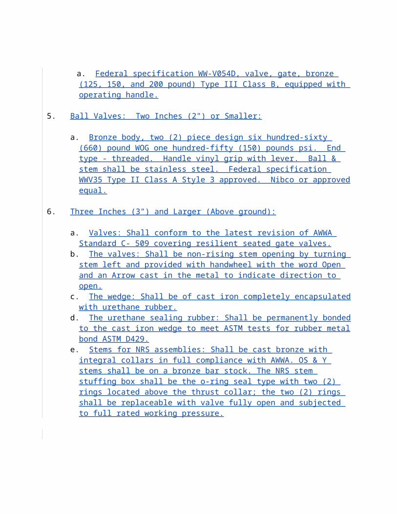
Video tapes shall be made upon the request of the Engineer. When requested, the video tape shall be made continuously as the camera is turned on and pulled through the line. Each tape shall be of the grade and quality best adapted to show the sewer in sharp detail, and shall be of 1/2 inch VHS cassette type, minimum play time 4 hours, or as required by the Owner. Each tape shall be numbered, dated and identified with sewer line station and location and an index of all tapes prepared referencing project, date, Contractor, mini-system, line section and tape counter number and be approved by the Engineer before accepting same. The tape shall become the property of the City.
Audio and visual identification of the manholes,line section, street, mini-system and other pertinent information as required by the Engineer shall be given at the beginning of each line section. Distances to all defects or other recorded points shall be given by audio description as well as the technician's observations of pipe condition, potential defects, leakage rates and all other previously described items. No outside noise, conversation or nonpertinent comments will be allowed to be recorded.
Any electrical service required by the Contractor for televising sewer lines shall be provided for by the Contractor.
The Contractor shall furnish all equipment required for taking photographs of the views which appear on the monitor. Photographs shall be taken at the discretion of the Engineer to show bad joints, cracks, and any other problem spots. These photographs are to supplement the video tape recordings and all costs involved in photography shall be considered incidental to the work.
Approval of the installation cleaning, television inspection, or video tapes will be made only after a complete review of all submitted logs and video tapes for the appropriate line sections. Should the Engineer determine, upon review, that the data submitted is inadequate due to log errors or omissions, improper or insufficient cleaning, equipment malfunctions, poor video quality, such as breaks in the continuous recording or poor or inadequate audio recording, no sound, no picture, poor photography results, incorrect distance measurements or other problems resulting in inaccurate or incomplete data, the Contractor shall schedule whatever operations are necessary to redo completely the television inspection, with any required cleaning, for the particular line section. The Contractor shall perform the rework within five (5) working days after receipt of the written notification by the Engineer.
Any retelevising of the lines due to poor cleaning, poor video tape quality, or insufficient logs as determined by the Engineer shall be at no additional expense to the Owner.
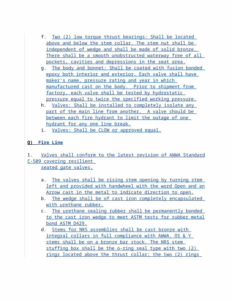
9. H) Forcemains
1. Material
a. Materials, equipment and supplies furnished and permanently incorporated into the project shall be of first quality in every respect, shall be constructed and finished to high standards of workmanship, and shall be the product of an approved reputable manufacturer. Materials shall be suitable for the service intended, shall reflect modern design and engineering and shall be fabricated in a first-class workmanlike manner. All materials, equipment and supplies shall be new and shall have not been in service at any time previous to installation, except as required in tests or incident to installation.
Ductile Iron Pipe:All ductile iron pipe supplied shall have a minimum tensile strength of 60,000 psi, a minimum yield strength of 42,000 psi and minimum elongation of 10% as specified by the latest ANSI A21.51. Thickness shall be a minimum of Class 51 as defined by ANSI A21.50. All pipe shall be coated outside with coal tar pitch. The inside pipe walls shall be double cement lined and bituminous coated for sizes up to and including 10" in diameter. For all pipe 12" in diameter and larger, the inside pipe walls shall be polyethylene, polyurethane or Protecto 401 ceramic epoxy lined with a minimum of 40 mil thickness. The lining shall conform to ASTM-C-418 and D-1248 specifications. All linings shall be applied by or be warranted by the pipe manufacturer. All ductile iron pipe shall have a brown polyethylene wrap with a minimum of 8 mils thickness and conform to ASTM specification D-1248-68.
Polyvinyl Chloride Pipe:For force main sizes 4" thru 12" where indicated on the plans, polyvinyl chloride pipe conforming to ASTM D-1784 meeting the latest revision of AWWA C-900 with an operating pressure rating of 150 PSI and with a DR of 18 shall be provided. For force main sizes 14" thru 24", where indicated on the plans shall be ductile iron. All PVC FM Shall be brown in color. FM under 4" shall be SDR 21 brown. Green pipe may be used if wrapped with brown tape at no more than 1' spacing.
Joints for cast iron and ductile iron pipe shall be either of the slip on type, using a single rubber gasket as the only sealing medium, mechanical joint conforming to ANSI A21.11 or, where shown on the plans shall have flanges conforming to the requirements of ANSI A21.10, Table 10.23. Joints between successive lengths of straight PVC pipe shall be compression type using a single elastromeric gasket, per ASTM D3139 and F477, as the sealing medium. Class 350 ductile iron mechanical joint fittings and valves shall be provided and installed where indicated. Special joints and fittings shall be provided as indicated on the plans.
2. Valves: All valves shall be epoxy coated inside and out. Valves shall be Clow/DeZurik eccentric valves
or approved equal.
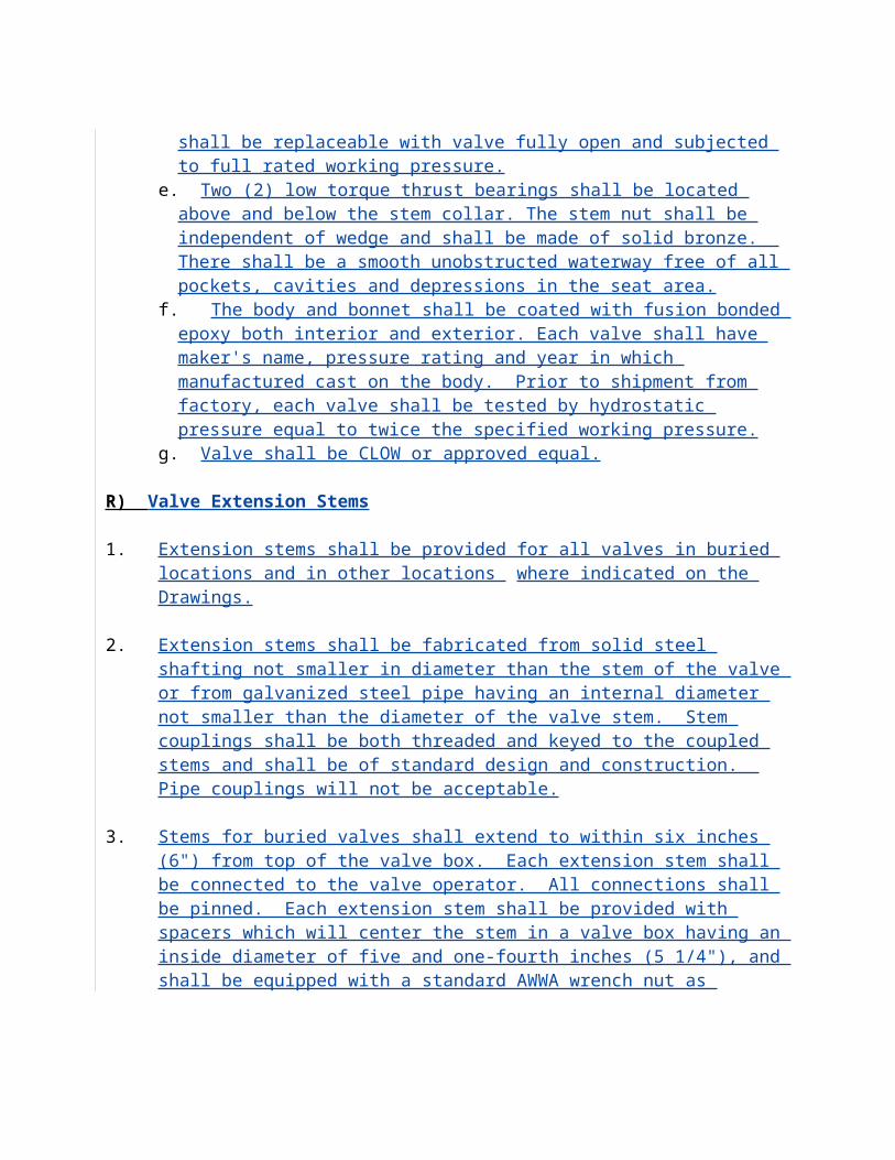
Plugs shall be of ASTM A126 Class B cast iron. The plug shall have a cylindrical seating surface eccentrically offset from the center of the plug shaft. The interference between the plug face and body seat, with the plug in the closed position, shall be externally adjustable in the field with the valve in the line under pressure. Plug shall be resilient faced with neoprene or hycar, suitable for use with sewage.
Valves shall have sleeve type metal bearings and shall be of sintered, oil impregnated permanently lubricated type 316 ASTM A743 Grade CF-8M in 1/2"-36 sizes.
Valve shaft seals shall be of the multiple V-ring type and shall be externally adjustable and repackable without removing the bonnet or actuator from the valve under pressure. Valves utilizing O-ring seals or non-adjustable packing shall not be acceptable. Valve pressure ratings shall be 175 psi through 12" and 150 psi for 14" through 72". Each valve shall be given a hydrostatic and seat test with test results being certified when required by the specifications.
All valves 6" and larger shall be equipped with gear actuators. All gearing shall be enclosed in semi-steel housing and be suitable for running in a lubricant with seals provided on all shafts to prevent entry of dirt and water into the actuator. The actuator shaft and the quadrant shall be supported on permanently lubricated bronze bearings. Actuators shall clearly indicate valve position and an adjustable stop shall be provided to set closing torque and to provide seat adjustment to compensate for change in pressure differential or flow direction change. All exposed nuts, bolts and washers shall be stainless steel.
Valves and gear actuators for buried or submerged service shall have seals on all shafts and gaskets on the valve and actuator covers to prevent the entry of water. Actuator mounting brackets for buried or submerged service shall be totally enclosed and shall have gasket seals. All exposed nuts, bolts, springs and washers shall be stainless steel.
All valves and actuators shall be as manufactured by DeZURIK or approved equal. 3. Valve Boxes:
All buried valves shall be provided with adjustable valve boxes approximately 5 inches in diameter with a minimum thickness of 3/16 inch and constructed so that the removable cover will not be thrown out by travel over it. Valves boxes shall be of sound, close grained cast iron, free from flaws and defects, built strong and rugged enough to withstand the shock of street traffic.
Valve boxes shall be of sufficient length to operate all valves buried in the ground. Valve boxes shall consist of base, center section, and top section with cover.
Valve boxes located in unpaved areas shall be Slip Type design to permit movement of the top section with transmitted forces onto the valve body.
All valve boxes shall have a 2' x 2' x 4" concrete pad around it. The concrete pad shall have a brass ID tag. The tag shall be 3" in diameter x 1/8" thick. There will be a 1/4 x 1/4" x 2" brass tang welded to the center of the circular tag which will be embedded into the valve pad. The tag will be stamped by the contractor. The information shall read as follows, size of valve and number of turns to fully open or close and an arrow which shows open is counterclockwise.
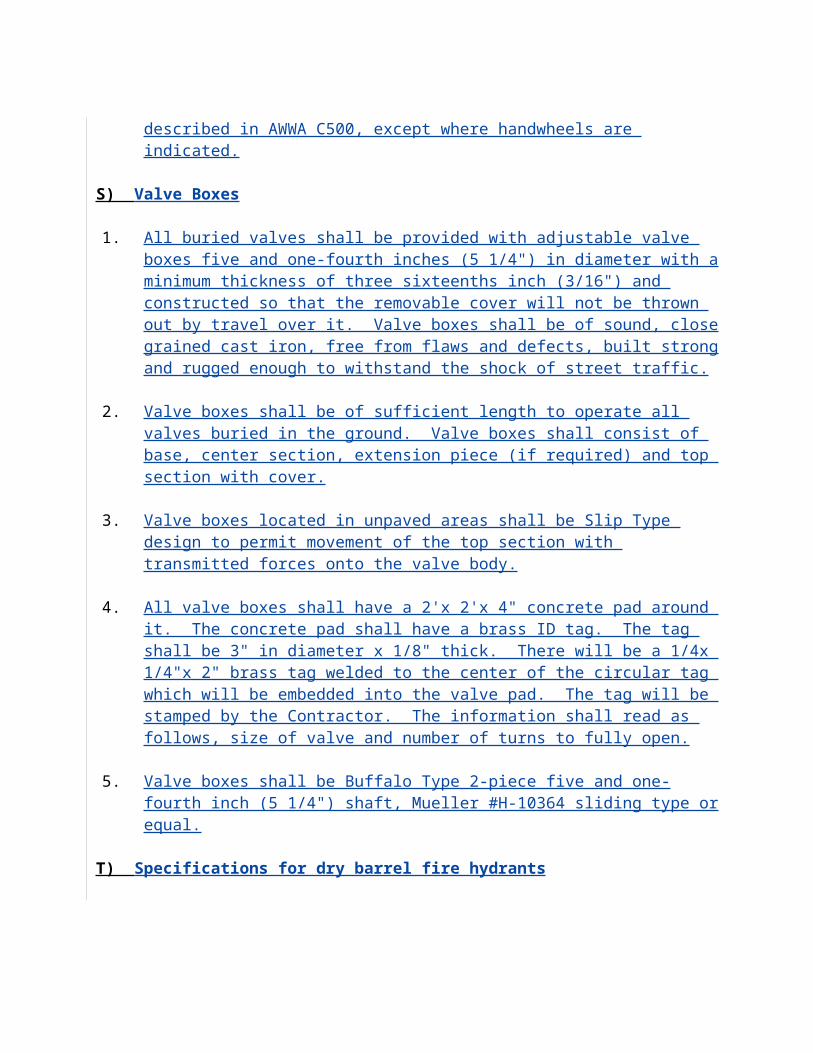
4. Valves shall be installed to completely isolate any part of the main line from another (i.e., 3 valves and 4 valves).
a. Valve top shall read SEWER.
5. Pipe laying:
a. Pressure pipe shall be installed in accordance with Type 4 ANSI/AWWA C-150/A21.150 Trench Conditions.
b. Cut sheets for the complete force main, unless waived by the Engineer, shall be submitted by the Contractor to the Sewer System=s Engineer for approval at least two (2) days prior to construction. This requirement will not relieve the Contractor of the responsibility to accurately record the Aas-built@ locations (horizontal and vertical) of piping, valving and appurtenances included in this section of the specifications.
c. The pipe shall be laid and maintained in the trench, to the required line and grade with the pipe barrel receiving continuous, uniform support and with no pressure exerted on the bells from the trench bottom. The interior of the pipes shall be thoroughly cleaned of all foreign matter before being lowered into the trench. During suspension of work for any reason, a suitable stopper shall be placed in the end of the pipe last laid to prevent mud or other foreign material from entering the pipe. Lines shall be laid straight with the depth of cover uniform with respect to finish grade, whether grading is completed or proposed at time of pipe installation.
d. Where a grade or slope is shown on the drawings, batter boards with string line or a laser beam paralleling design grade shall be used by the Contractor to assure conformance to required grade. No abrupt changes in vertical or horizontal alignment will be allowed. All fittings at bends in the pipelines shall be properly braced with concrete thrust blocks as detailed. Any pipe found defective shall be immediately removed and replaced with sound pipe. Minimum cover shall be 36-inches, unless otherwise specified or directed by the Engineer.
e. Megalug restraining joints or concrete thrust blocks shall be placed at all bends, tees, plugs, and other fittings to provide lateral and/or vertical support. Thrust blocks shall conform to the details shown on the plans.
f. The joints of all pipe lines shall be made absolutely tight. Where shown on plans, or where, in the opinion of the Engineer, settlement or vibration is likely to occur, bolted mechanical type joints shall be used as specified herein.
g. Mechanical joints shall be made up using annealed high strength cast iron bolts and having either plain or duck tipped rubber gaskets, as recommended by the manufacturer. All types of mechanical joint pipes shall be laid and jointed in full conformance with manfacturers recommendations.
h. Push on joints shall be made in strict and complete compliance with the manufacturer=s recommendations.
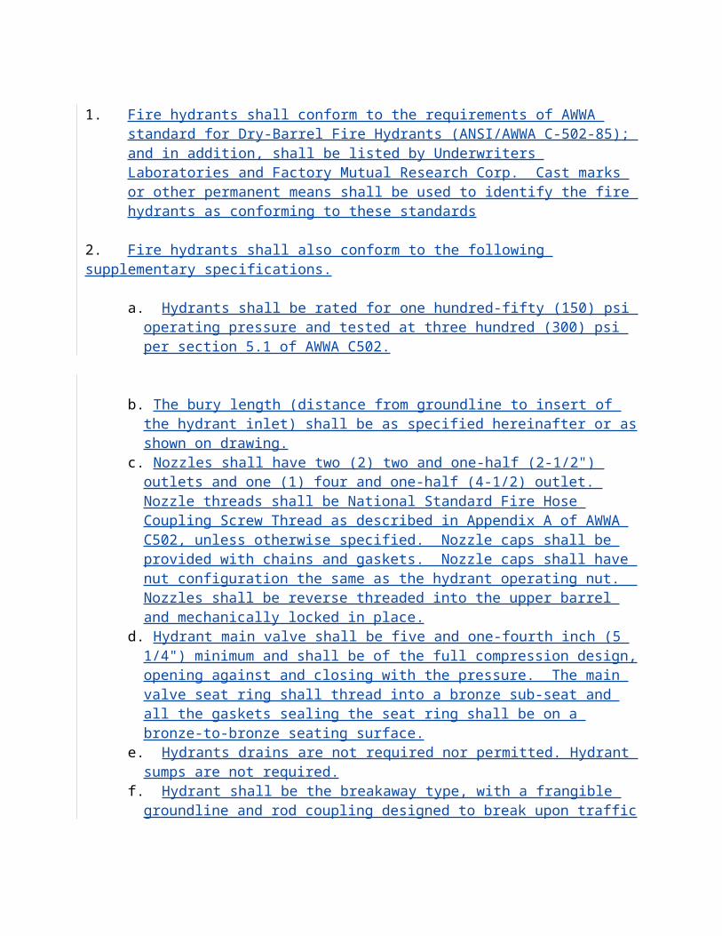
i. There shall be no occasion wherein any fitting is tapped directly into the pipe. In every case, a double strap service saddle shall be used.
j. It is the responsibility of the Contractor to supply to the Owner detailed as-built drawings showing location of all fittings on the force main. Location ties shall be accurate and complete, in accordance with the as-built record drawing requirement.
6. Air Release Valves and Chambers:
a. All air release valves shall be 2" APCO 400 WA air release valves complete with all accessories including backwash assembly, or equal. Manual air release valve will have easy access for operation and replacement maintenance. Use of manual valves requires specific approval of the city engineer
b. Automatic air release valves should be used and accessories shall be connected to the main by a two-inch diameter tap using a Meuller, or approved equal, 2" corporation cock, brass nipple and double stainless steel, or as approved by the Engineer, strap service saddle. Air release assemblies and structures shall have a double entry cover U.S.F. No. 671-AFM, or equal, for easy accessibility to the Chamber and shall be built as shown on the detail drawings. All air release valves, accessories, and valve chambers shall be installed and equipped as shown on the standard detail drawing.
7. Testing of Forcemains:
a. No testing shall be done until all thrust blocks are in place or joints are restrained. While the pipe is being filled with water, care shall be exercised to permit the escape of air from the pipe. All sewage force main lines shall be subjected to a pressure test of 150 psi for a minimum of two hours. The Contractor will supply necessary pressure pumps, gauge, snubber, and an oil drum with head removed for the purpose of metering water used.
b. Any leaks found shall be repaired and the test repeated until the line is satisfactorily watertight. The Contractor shall pay all costs in connection with pressure treating. The Contractor shall pay all costs in connection with the pressure testing.
8. Special Structures and Crossings:
Pipe/size 100 PSI 150 PSI4" .27 .336" .41 .508" .54 .6610" .68 .8312" .81 .9914" .94 1.1616" 1.08 1.3218" 1.21 1.5020" 1.35 1.6524" 1.62 1.9830" 2.03 2.4836" 2.43 2.98
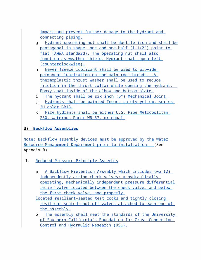
a. Special structures and crossing shall be constructed in accordance with the details shown on the plans or as directed. All materials and workmanship shall be as specified herein.
9. Casings:
a. All casings shall be installed accurately to line and grade and shall meet all requirements of the prevailing rights-of-way holder. Casings shall be new and of domestic material and manufacture.
b. Pipe casing shall be welded steel. The pipe casing shall be steel and conform to the requirements of AWWA Standard C-200 and ASTM A-139, Grade B. The pipe shall be coated internally and externally with coal-tar primer followed by a hot coal-tar enamel in accordance with AWWA Standard C-203.
c. Joints shall be full penetration but welded in accordance with the requirements of AWWA Standard C-206. The joints shall be double groove welded with continuous circumferential welds and field lined and coated in accordance with AWWA C-203.
d. All casings shall be in accordance with the specifications as shown on the plans and detail sheets.
10. Carrier Pipe:
a. All Carrier Pipe: Shall be 51 ductile iron pipe with joint restraints. The carrier pipe shall be installed in the casing on spacer skids. Casing spacer skids shall be the bolt on style with a two section shell fabricated of 14 gauge fully passivated 304 stainless steel. The shell sections shall have flanges and be secured to the carrier pipe with not less than 5/16 inch diameter 304 stainless steel nuts and bolts with lock washers. The spacer shell shall be lined with a 0.090-inch PVC liner having an 85 to 90 durometer hardness. Runners shall be ultra high molecular weight polymer with high abrasion resistance and a low coefficient of friction. The runners shall be supported by 304 stainless steel supports welded to the shell and welds passivated. The supports shall be dimensioned to center the carrier pipe in the casing with a top clearance of one half inch. The height of the supports and runners combined shall be sufficient to provide not less than three fourths inch between the casing pipe and outside diameter of the carrier pipe joints. Provide not less than three spacers for each length of carrier pipe. Casing spacers shall be equal to those manufactured by Cascade Waterworks Manufacturing Company, Yorkville, Illinois.
11. Force Main Identification:
a. Sewage Force Main Pipe: Shall be identified with the words "Sewage Force Main" prominently displayed at intervals no greater than three feet between
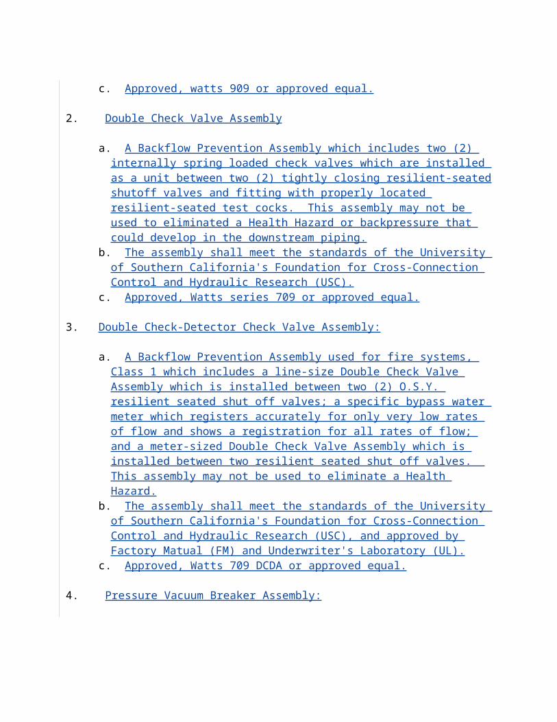
labels. Raw sewage force mains shall be green pipe wrapped with 2" wide brown vinyl tape. In all cases, a properly colored metallic location tape shall be buried approximately 12" above the pipe. PVC force main shall be buried with a #12 locator wire.
12. Valve Box Cover:
a. Buried valves: Shall, unless shown otherwise, have the operator shaft extended as required to position the 2" operating nut within 12" of finished grade. The shaft and nut shall be full enclosed in a vertical protective pipe set firmly upon the valve operator housing and extending fully into the valve box/cover assembly. Valve box/cover shall be cast iron with "Sewer" on the cover. The cover shall be centered in a two feet square concrete pad at finished grade, all in accordance with standard details. The pad shall have a 3" brass tag embedded into concrete indicating force main valve, number of turns, and date installed.
13. Valves
a. Shall be of the non-lubricated eccentric type with resilient faced plugs and shall be furnished with end connections as shown on the plans. Mechanical joint ends shall be to the AWWA Standard C111-64, grooved ends per AWWA C-606-87.
b. Shall have sleeve type metal bearings and shall be of sintered, oil impregnated permanently lubricated type 316 ASTM A743 Garde CF-8M in 1/3"-36" sizes.
14. Valves bodies:
a. Shall be of ASTM A126 Class B cast iron. Bodies in 4" and larger valves shall be furnished with 1/8" welded overlay seat of not less than 90% pure nickel. Seat area shall be raised, with raised surface completely covered with weld to insure that the plug face contacts only nickel. Screwed-in seats shall not be acceptable.
15. Plugs:
a. Shall be of ASTM A126 Class B cast iron. The plug shall have a cylindrical seating surface eccentrically offset from the center of the plug shaft. The interference between the plug face and body seat, with the plug in the closed position, shall be externally adjustable in the field with the valve in the line under pressure. Plug shall be resilient faced with neoprene or hycar, suitable for use with sewage.
16. Valve shaft seals:
a. Shall be of the multiple V-ring type and shall be externally adjustable and repackable without moving the bonnet or actuator from the valve under pressure. Valves utilizing O-ring seals or non-adjustable packing shall be not be acceptable.
17. Valve pressure ratings:
a. Shall be 175 psi through 12" and 150 psi for 14" through 72". Each valve shall be given a hydrostatic and seat test with test results being certified when required by the specifications.
18. All valves 6" and larger:
a. Shall be equipped with gear actuators. All gearing shall be enclosed in a semi-steel housing and be suitable for running in a lubricant with seals provided on all shafts to prevent entry of dirt and water into the actuator. The actuator shaft and the quadrant shall be supported on permanently lubricated bronze bearings. Actuators shall clearly indicate valve position and an adjustable stop shall be provided to set closing torque and provide seat adjustment to compensate for change in pressure differential or flow direction change. All exposed nuts, bolts and washers shall be zinc plated.
19. Valves and gear actuators for buried or submerged service:
a. Shall have seals on all shafts and gaskets on the valve and actuator covers to prevent the entry of water. Actuator mounting brackets for buried or submerged service shall be totally enclosed and shall have gasket seals. All exposed nuts, bolts and springs and washers shall be stainless steel. All valves and actuators shall be as manufactured by DeZURIK or approved equal.
TECHNICAL PROVISIONS FOR THE CONSTRUCTION OF SANITARY SEWER LIFT STATIONS
CITY OF PLANT CITY, FLORIDA
STANDARD SUBMERSIBLE LIFT STATION
ELECTRICAL AND CONTROL SPECIFICATION
Liftstation Generator Specifications
A. When a generator is installed with the liftstation the following must be provided; a mainline breaker system with a transfer switch matching frame size (i.e. 100, 225, 440, 800,or 1200 amp) must be installed. It shall be noted that the breaker system and transferswitch have the same amp rating. This breaker and transfer switch configuration shall becapable of running two motors (of same horsepower rating which can vary in size based
on service application) at the same time. This shall meet or exceed all NEMA (MG-1) standards.
B. Diesel Engine: The engine shall be a four (4) cycle engine, water cooled, having no less than four (4) cylinders with a minimum brake horsepower rating of 1.5 HP/KW in an
ambient temperature of 125o F and at 2,000 feet altitude, with a rotating speed not exceeding 1,800 RPM, designed to operate on #2 diesel fuel.
C. Governor: Engine shall be equipped with a governor to maintain frequency regulation within 3% (plus or minus 1.8 hertz) from no load to full load. The frequency at any constant load, including no load, shall remain within a steady state band width of 0.25% of rated frequency. The governor shall not permit frequency modulation (defined as the number of times per second that the frequency varies from the average frequency in cyclic manner) to exceed one (1) cycle per second. Governor shall be a hydraulic or electronic type.
D. Generator:
D.1The generator shall be of type specially designed for induction motor starting. It shall be capable with its prime mover of starting and running continuously, for the duration of a normal power outage. The voltage drop under starting conditions specified shall be such as to maintain, without impairment, all plant operations functions.
D.2The generator shall be four pole, brushless, 12 lead reconnectable of drip-proof con-struction with amortisseur windings. Insulation shall be Class F with epoxy varnish.
Generator field current shall be controlled by a rotating thyrist or bridge module optically coupled to a firing circuit type voltage regulator. The exciter shall be 24 pole permanent magnet type. Generators controlled by wound field exciters will not be accepted unless they meet the following performance. Generator shall be connected for 120/240 volt AC, 60 hertz, three-phase, four-wire service.
D.3Voltage regulator shall be a solid-state, frequency compensated type with +2% or rate voltage, from no load to rated load. Voltage adjustment range shall be plus orminus 5% of rated voltage.
E. Fuel System: System shall have a fuel filter with replaceable element conveniently located in one accessible housing ahead of injection pump so that fuel has been thoroughly filtered before it reaches the pump. Fuel filter elements will be of the replaceable type that may be easily removed with-out breaking any fuel line connections or disturbing the fuel pump. Engine shall be equipped with a gear type, engine driven, fuel transfer pump capable of lifting fuel 15 feet, for supplying fuel throughfilters to the injection pump at constant pressure. A complete system with lines, transfer pump, injectors and flexible fuel lines shall be furnished.
F. Lubrication System: Engine shall be equipped with a pressure lubrication system supplying a continuous flow of lubricant, under pressure, to all moving parts.Pistons will be spray cooled. Circulation shall be by means of a positive displacement pump, gear type. The lubrication system shall include full-flow filters and series connected oil cooler of sufficient size to properly cool all lubricating oil circulated. Filter systems shall be equipped with a spring-loaded bypass valve as an insurance against stoppage of lubricating oil circulation in event the filters become clogged. A 15 second time delay on low oil pressure shall be provided for starting, but shall not cause a delay on shutdown. Equipped with a low oil pressure cut off switch wired to the safety shutdown system of the unit.
F.1 The engine shall be equipped with piping and gate valves as required to drain the crankcase oil. Piping shall be routed so the oil may be drained without the connection of hose or piping by the Owner. Valve shall be located inside enclosure.
F.2 The generator shall be set on an elevated pad of sufficient height (minimum 6") above the surrounding floor or grade to allow the oil to be drained into container
supplied with generator.
G. Cooling System: The generating plant shall be equipped with a unit-mounted cooling system to maintain the engine at recommended temperature level when the generating plant is delivering full-rated load in an ambient temperature of 125o F.
G.1 The cooling system shall consist of a radiator, pusher fan, fan shroud, fan and core guards, surge tank, engine driving centrifugal type water circulating pump, filler and cap. The cooling system shall be designed and engineered to be a functional unit capable of operating with a 50% ethylene glycol and 50% water solution.
G.2Cooling system shall be winterized for operation in temperature to 0o F.
G.3Radiator shall be equipped with a low level coolant float switch and wiredto the safety shutdown system of the unit.
H. Base: The generating plant shall be mounted on a common structural steel, skid type base
designed to maintain proper alignment of components. Suitable vibration isolators shall be furnished which, when installed between the engine generator skid and mounting surface, will permit only 5% of the unit=s vibration to be transmitted. The vibration isolators shall be securely mounted on the mounting surface.
I. Engine Generator Controls: The panel shall be a solid-state, microprocessor-based engine control module shock mounted on the generator in a gasketed NEMA1/1P 22 enclosure. The panel shall have digital LCD back lighted display indicating the following:
Engine RPM;Battery DC volts;
Coolant temperature;Lube oil pressure;Generator set operating hours;
System diagnostic codes (for troubleshooting);
I.1 Diagnostic codes for the following conditions shall be provided:
Loss of magnetic speed pickup signal;Loss of DSU signal;
Loss of programmed settings (i.e. cycle crank, cooldown timers, etc.);Invalid engine control switch signal;
Shutdown not control originated (i.e. fuel deprivation); Module internal fault.
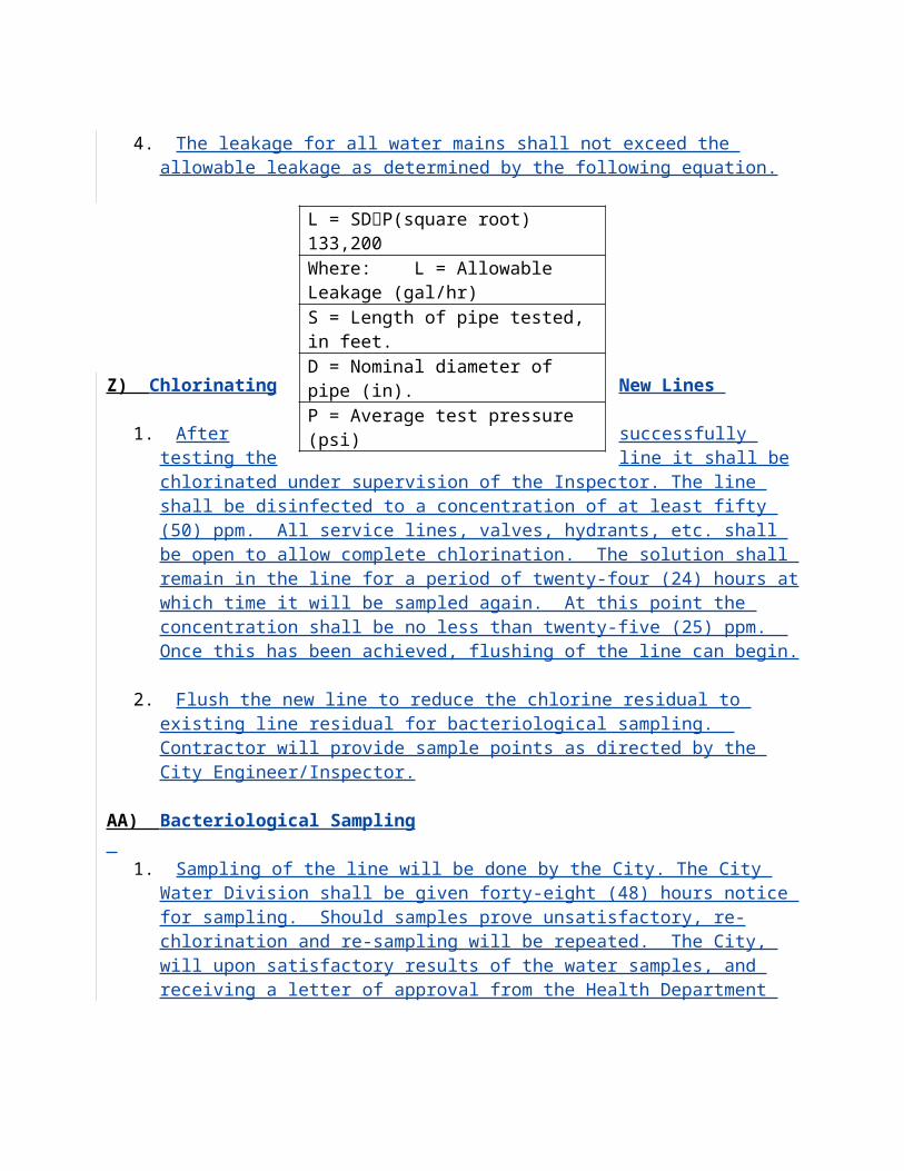
I.2 Automatic/manual start-stop controls with the following safety shutdowns with LED indicators shall be provided:
Overspeed;Low lube oil pressure, two-state protection for low idle/high idle;
High coolant temperature; Overcrank;Safety shutdown for all system diagnostic codes above;
Loss of engine coolant;Emergency stop.
I.3 Control panel shall have cooldown timer (adjustable 0-30 minutes); four position engine control switch; LED indication and LCD display testswitch; voltage adjust potentionmeter+ 10% -25% range; four positionampmeter/voltmeter phase selector switch, three current transformer andsolid state, microprocessor-based digital AC metering module displaying AC volts, AC amps and frequency.
I.4 Generator shall have annunciator for generator faults, low coolant temperature, battery charger fault, low fuel in storage tank and fuel leak detected. Annunciator shall be mounted on generator set control system. Annunciator shall have interlock with telemetry system for trouble, generator running and generator on line conditions.
J. Engine Instruments: Engine instruments shall include water temperature, lubricating oil pressure, lubricating oil temperature, battery volt meter, engine lapse runtime
meter, tachometer and fuel pressure gauges.
K. Generator Circuit Breaker: Generator circuit breaker shall be a molded case thermal-magnetic type housed in a gasketed NEMA 4X enclosure. Circuit breaker shall be a 3 pole 600 volt rated as indicated on the drawings.
L. The Disconnect and transfer switch shall be housed inside a NEMA 4 x enclosure if not inside the generator enclosure. (Stainless steel).
WEATHERPROOF ENCLOSURE SKID- MOUNTED:
A. The complete engine-generator set shall be enclosed in a modular weather proof enclosure. The enclosure shall be constructed with removable side and end panels. These panels shall be made out of 12 gauge steel. The unit shall have continuous hinged side doors and at the control end. It shall be equipped with key locks for ease of engine maintenance and a three point latch system.There shall be expanded metal grating or
radiator core guard in front for the radiator grill and fixed punched louvered air intake ports on the enclosure sides and rear for proper air circulation within the housing. The complete generator set and housing shall be prime painted and have two finishcoats of protective enamel paint. Provide lifting eyes and spreader bar reinforcement
for crane unloading.
B. The generator breaker, generator control panel,VAC distribution panel- board, 120/240 batteries, battery charger, and accessories shall be mounted in the enclosure. Control wire connection between starting and safety circuits shall be preconnected before the engine-generator set is delivered. Provisions shall be made for mounting batteries andrack inside the enclosure. Thermostatically controlled exhaust fan for enclosure and space heaters for the generator and enclosure shall be provided.The distribution panelboard shall supply power to the jacket water heater, battery charger, exhaust fan, space heaters, etc. Enclosurers for electrical equipment shall be NEMA 4X if its exposed to weather.
C. The engine oil and radiator drain lines shall be brought to the outside of the enclosure. A globe type shut off valve shall be installed in each drain line inside the enclosure for security.
D. Exhaust System: Furnish and install according to manufacturer’s recommendations, silencer, wall thimbles, stainless steel flexible exhaust connections a minimum of eighteen (18”) inches long, flanges, hangers and supports, pipe and fittings, and insulation as specified herein or as indicated on drawings to provide a complete and operable exhaust system. The system shall be mounted so that the engine shall not
be supporting its weight nor will thermal expansion be imposed on the engine.
D.1 Silencer shall be Maxim M-41 with flexible connection at engine. Silencer shall have bolted flange connections.
D.2Piping shall be seamless steel conforming to ASTM A53, Grade B, schedule 40 black steel. Exhaust pipe shall be painted with high temperature paint. Exhaust pipe shall be fitted with a ninety (90o ) degree tail piece and stainless steel weather cap. Fittings shall be seamless, black, standard weight, butt-weld type.
FUEL OIL STORAGE SYSTEM:
A. Provide a fuel oil storage system consisting of an in-base tank, piping, fuel oil level gauge and miscellaneous appurtenances necessary for a complete and working installation as specified herein.
B. In-base Fuel Storage Tank: The in-base fuel tank shall be of double wall construction andshall have an interstitial leak detection system wired to the generator control panel. The
tank shall be provided by the standby generator set manufacturer and shall serve as a mounting base for the generator set. The tank shall contain structural steel members sufficient to support the generator, enclosure, exhaust system and other related equipment. The base tank bottom shall be a minimum of 1/4-inch plate. Tank shall be 12" to 18" high. The tank shall have lifting eyes for four point lifting. The tank length and width shall be as required to provide a minimum of 200 gallon capacity. Tank shall have low fuel level contact set at 28% full, fuel level gauge, lockable fill cap, and vent pipe which shall be installed through the enclosure roof. The base tank shall be pressure tested at 15 psi, cleaned of rust, oil, and welding slag, and primed for painting. Two coats of high quality enamel paint shall be applied over the primer. The tank interior shall not be coated. The lockable tank fill cap shall be located external to the generator enclosure. The tank shall be provided full with fuel. The tank shall be in complete compliance with UL 142 and shall be labeled as such. Provide tank
accessories as specified in D on page A-10.
C. Fuel Oil Piping: Furnish and install fuel piping systems including vent lines, fill lines, suction lines, return lines, gauge lines and sounding lines as required to provide a complete and working diesel fuel piping system. Piping shall be black steel, Schedule
40, conforming to ASTM A53 specification for Welded and Seamless Steel Pipe. Fittings shall be malleable iron screwed fittings conforming to ASTM B16.3 specifications. Pipe and fittings shall be coated and wrapped with tar material as per NFPA No. 30, 31 and 37 when installed below grade. A horizontal swing check valve, gate valve, and fuel oil strainer shall be provide in the suction line. Hand-operated shut-off valve will not be permitted in the fuel oil return line. All valves shall be Crane, Jenkins, Walworth or equal, designed for 125 lbs. working pressure.
D. Fuel Tank and Pipe Accessories: Provide the following accessories for a completeinstallation.
D.1Valves: All valves shall be designed for 125 lbs. working pressure. Out-let and drain valves for aboveground tank shall be a 2-inch steel ball valves. Plug outlet of drain valve. Acceptable: Crane, Jenkins, Walworth, or approved equal.
D.2Fill Adapter: Provide 4-inch fill pipe adaptor with lockable cap. Acceptable: OPW No. 633 - T -4-inch with OPW No.634-TT - 4- inch, or equal.
D.3Vent Cap: Provide vent cap with 40 mesh brass screen and drain spouts. Size shall be 2-inch, minimum. Acceptable: OPW No. 23 or approved equal.
E. Fuel Oil Level Gauge: Provide as specified herein a fully automatic liquid level gauge forthe generator in-base fuel tank. Gauge shall be temperature compensated, balanced hy-
draulic type, providing continuous automatic indication in gallons on a circular dial. Gauge shall be as manufactured by Hersey Products, Inc., or equal. Gauge shall be
located for ease of observation.
E.1 Liquid level gauge shall be supplied with a set of contacts to give indicationof a low fuel level. Set point shall be adjustable. Contacts shall be connected to the generator annunciator.
SYSTEM OPERATION:
A. The generating plant shall automatically start upon a signal from the automatic transfer switch.
B. After the transfer switch has transferred back to normal, the generating plant shall be allowed to operate at no load for an adjustable time period of 2 to 30 minutes
to allow it to cool before shutdown.
EMERGENCY SHUTDOWN:
An emergency shutdown shall be installed on the weatherproof enclosure. When the push-down is activated, the engine-generator set shall be shut down.
TESTING:
A. Prior to acceptance, any defects which become evident during this test shall be corrected at no expense to the City.
B. The services of a factory trained service engineer who is specifically trained on the type of equipment herein specified shall be provided to fully inspect the installation, calibrate the equipment and supervise testing.
C. Upon completion of testing the services, the above engineer shall be provided for instruction of the City’s operating and maintenance personnel. The in-structions shall include operating and maintenance procedures specifically written for the equipment installed and not generally written to cover all options available. The City shall release the services of the service engineer once they are completely satisfied with the instructions.
D. The transfer switch shall be operationally tested as part of the complete system to verify satisfactory operation under the worse case conditions to be provided by the electrical system.
E. PLC must have connection for a Laptop Computer Interphase, any software or hardware
needed to perform this task is to be provided by developer.
F. Software must be capable of changing set points,Making report, etc.
G. Training and support must be provided.
TECHNICAL PROVISIONS FOR THE CONSTRUCTION OFSANITARY SEWER LIFT STATIONS
INTRODUCTION
This section applies to ‘City ACCEPTED’ wastewater pump stations with peak design of 1500 GPM or less per pump or station that requires motor sizing smaller than 20 hp. All such wastewater pump stations shall be submersible type stations. The type and bases for design of all other stations shall be reviewed with the City and the approval obtained before proceeding with design.
Only equipment compatible with existing components and operations will be considered. It is the scope of this provision to insure uniform operation and to minimize spare part inventory. Interchangeability with existing equipment and emergency connection to this equipment with no adverse effect on operations will be required.
All wastewater pump stations that are not accepted by the City, yet intend to discharge into the City’s wastewater collection system shall have a current repair and maintenance contact name and telephone number visibly attached to the outside face of the control panel. The owner shall keep access available to the pump station at all times. The City shall have the right to enter said station in times of emergencies to allow control of wastewater discharged into the City’s system.
Contractor/Owner will be responsible for all permits and fees required by all organizations responsible for such fees and permits including, but not limited to, CITY, COUNTY, STATE and FEDERAL Governments.
SITE LAYOUT, SIZING AND EASEMENT REQUIREMENTS
Pump station sites shall be laid out and sized as delineated on the ‘Pump Station Site Plan’ in the ‘Standard Drawings.’ Site must meet all setback and landscape requirements found in City zoning ordinance. Lift station site within limits of utility easement shall be uniform and level with top elevations of wet well and valve vault 3 inches above finish grade. Finish grade is defined as top of bedding rock within confine of pump station security fence. The Developer shall dedicate pump station by warranty deed or plat to the City. Dedicated easement shall also be required around the site as delineated on the ‘Pump Station Site Plan’ in the ‘Standard Drawings.’ In general, the site for the paved access road shall also be dedicated to the City by warranty deed or plan. An exception to this requirement may be allowed on a case-by-case basis in the form of an ingress/egress easement for the access road.
SITE ACCESSIBILITY
The pump station shall be readily accessible by maintenance vehicles during all weather conditions. The access road to the pumping station shall be paved. The facility shall not be located in road right-of-way. In a phased development, a stabilized access road may be accepted during the initial phase with paving to be accomplished in the later phase.
AREA FLOODING
Wastewater pumping station structures and electrical/mechanical equipment shall be protected from physical damage from a 100-year flood. Regulations of Local, State and Federal agencies regarding flood plain construction shall be considered.
DESIGN FLOWS
Design flows shall be based upon the total ultimate development flow from all contributory areas to the pump station. The design average daily flow shall be based on Equivalent Residential Unit (ERU) determination.
The design pumping capability of the station shall be based upon the Peak Design Flow which shall be calculated by multiplying the design average flow with the applicable minimum peaking factors as outlined below:
Minimum Peaking FactorDesign Average Daily Flow for Peak Design Flow
Flows to 100,000 GPD 4.0
100,000 GPD to 250,000 GPD 3.5250,000 GPD to 1,000,000 GPD 3.0Flows greater than 1,000,000 GPD 2.5
For design average daily flow above 2,000,000 GPD, peaking at factors less than 2.5 may be considered if substantiated by extensive data. Under no circumstances shall peaking factors less than 2.0 be allowed.
WET WELL AND VALVE VAULT DESIGN
Wet well shall be minimum six-foot (6’) diameter and shall have a minimum four and one-half-foot (4 ½’) depth below the lowest invert. Additional depth shall be provided based on station design and cycle time.
Pumping levels shall be adjusted to provide a minimum capacity between normal operational water levels sufficient to allow a minimum of five (5) minutes between successive starts of the pumps.
Pump-off water levels shall provide adequate submergence to preclude pump inlet vortexing or air binding. Operational maximum water levels shall not exceed the invert elevation of the influent pipe.
The wet well floor shall have a minimum slope of 1 to 1 to the hopper bottom. The horizontal area of the hopper bottom shall be no greater than necessary for proper installation and function of the pump inlet.
No fixed interior ladders shall be permitted in the wet well.
Locate manhole within limits of fenced-in area to allow isolation of wet well during by-pass operations. Manhole shall be lined as required for wet well. Only one wastewater inlet connection shall be permitted to a wet well. All openings in wet well and valve vault shall be manufactured at foundry. No field coring is permitted without City approval.
Wet well shall be constructed of precast units. Cast-in-place shall not be permitted.
Precast wetwells shall conform to specifications for Precast Reinforced Concrete Sections, ASTM Designation C478, except as otherwise specified below:
The minimum wall thickness shall be 8” for all wet wells. Precast wet wells shall be constructed with a monolithic base structure as shown on the ‘Standard Drawings.’ The minimum base thickness shall be 12 inches. The precast top slab shall have thickness of 10 inches (10”). Concrete for wet wells shall be Type II, 4000 psi at 28 days. Barrel, top and base sections shall have tongue and groove joints. All joints will use ‘O’ ring Gaskets for seal between well sections. The date of manufacture and the name or trademark of the manufacturer shall be
clearly marked on each precast section. Sections shall be cured by an approved method for at last 28 days prior to painting and shall not be shipped until at least two days after having been painted. Lifting rings or non-penetrating lift holes shall be provided for after having been painted. Lifting rings or non-penetrating lift holes shall be provided for handling precast wet well sections. Non-penetrating lift holes shall be filled with non-shrink grout after installation of the sections. Concrete surfaces shall have form oil, curing compounds, dust, dirt and other interfering materials removed by sandblasting and shall be fully cured prior to the application of any coatings.
Interior of wet well shall have a high-density polyethylene (HDPE) and Polypropylene Copolymer (PPR) thermal plastic liner installed at the foundry as an integral part of the concrete casting process. Acceptable manufacturer: Argu Sure Grip or approved equal.
Wet Well Structure Inspection
The quality of all materials, the process of manufacture and the finished sections shall be subject to inspection and approval by the City. Such inspection may be made at the place of manufacture, or at the site after delivery, or at both places and the section shall be subject to rejection at any time on account of failure to meet any of the specification requirements even though sample sections may have been accepted as satisfactory at the place of manufacture. Sections rejected after delivery to the job shall be marked for identification and shall be removed from the job at once. All sections which have been damaged after delivery will be rejected and, if already installed, removed and replaced, entirely at the contractor’s expense.
At the time of inspection, the sections will be carefully examined for compliance with the specified ASTM designation and with the approved manufacturer’s drawings. All sections shall be inspected for general appearance, dimension, “scratch-strength” blisters, cracks, roughness, soundness, etc. The surface shall be dense and close-textured to form an integral watertight unit.
Wet Well Placement
Base sections shall be placed on bedding rock conforming to the requirements on standard drawing. The bedding rock shall be firmly tamped and made smooth and level to assure uniform contact and support of the precast structure.
A precast base section shall be carefully placed on the prepared bedding so as to be fully and uniformly supported in true alignment and making sure that all entering pipes can be inserted on proper grade.
Precast wet well section shall be handled by lift rings or non-penetrating lift holes. Such holes shall be filled with non-shrink grout after installation of the wet well.
The first precast sections shall be placed and carefully adjusted to true grade and alignment. All inlet pipes shall be properly installed so as to form an integral watertight unit. The sections shall
be uniformly supported by the base structure and shall not bear directly on any of the pipes. Precast sections shall be placed and aligned to provide vertical alignment with a ¼ inch maximum tolerance per five (5) feet of depth. The completed wet well shall be rigid, true to dimensions and water tight.
Valve vault floor shall slope to center and have a solid PVC floor drain with stainless steel grating. Floor drain shall be connected to wet well as shown on ‘Standard Drawings.’ Drain line shall include two (2) in-line “P” traps; one located under drain below valve vault and one located at the discharge of drain in wet well to prevent corrosive gases from entering valve vault.
All pipe openings shall be sealed with EMBCO non-shrink grout or approved equal.
Both the wet well and the valve vault shall be furnished with an access frame and cover. Equipment furnished shall include the necessary aluminum access frames complete with hinged and slide bar equipped, stainless steel upper guide holder, and level sensor cable holder. The frames shall be cased in structure at foundry with upper guide holder securely mounted above the pumps. Doors shall be of aluminum checkered plate. The access cover and frame with steel hardware shall be installed as shown on the ‘Standard Drawings.’ Wet well cover shall be minimum of 30”X 48”, valve box shall be minimum of 48” X 48” double door. Both covers shall be aluminum locking type similar and equal to U.S. Foundry Corp. Model APS300 (wet well) and Model APD300 (valve vault). Larger size covers may be required to accommodate pump equipment.
Grounding wire to be poured into top slabs and connected to access frames as outlined in the electrical requirements
Buoyancy of wet well and valve vault structures shall be considered and adequate provisions shall be made for protection. Wet well and valve vault structures shall be installed as shown on the ‘Standard Drawings.’ Wet well construction shall be in conformance with the pre-cast structure specifications as outlined on ‘Standard Drawings.’
Exterior of wet well to receive at foundry two coats (black over red) of coal tar epoxy paint (8mm dry film thickness each). This is to be continuous coating free of “pin holes” and/or voids and is to be applied in accordance with manufacturer instructions as not to void manufacturer’s warranty. Technical specifications and general information concerning the specific coating used shall be supplied by the paint manufacturer and be included as part of the required submittals as outlined in Sub-Section L.13. After wet well top slab, base and all sections have been permanently set in place, seal outside with non-shrink grout prior to exterior application of protective epoxy coal tar coating. (Koppers Bitumastic 300m, no substitute allowed).
PUMP AND MOTOR SIZING
Pump station shall be capable of pumping the peak design flow with the largest pumping unit out of service. Pumps shall be capable of meeting all system hydraulic conditions without
overloading the motors. In addition, a minimum of 3-hp motor shall be required unless prior arrangements have been approved by the City. Head capacity curves shall be prepared and submitted to the City along with the pump station plans. Such curves shall be based upon friction losses through force mains. Determination of such friction loss shall be based on the Hazen and Williams formula, the value for “C” shall be 120 for ductile iron pipe and 130 for PVC. “C” values greater than 130 shall not be allowed. When initially installed, force mains may have a significantly higher “C” factor. The higher “C” factor should be considered only in calculating maximum power requirements and duty cycle time of the motor. Head capacity curves shall verify that the pumps are operating at peak efficiency and are suitable for the design flow applications. Pump and motor selection and head capacity curves shall reflect hydraulic conditions in cases where receiving force main systems are interconnected to additional pumping stations.
For pumping stations with peak design flow of 1500 GPM or less, a minimum of two pump units shall be provided. Where the peak design flow exceeds 1500 GPM, three or more pump units shall be provided. Stations with three or more pump units may require on site stand by generator capabilities as determined by City.
Developer’s Engineer shall submit design calculations for all wastewater pump stations. Calculations shall include head capacity curves with copies of manufacturers pump curves, hydraulic analysis of force main systems, operating cycle calculations with wet well sizing, and buoyancy calculations. Pump impeller selection shall be based on a non-overloading factor in relation to the submitted pump curve.
PUMP EQUIPMENT DESIGN AND CONSTRUCTION
The pumping equipment covered by these specifications is intended to be standard pumping equipment of proven ability as manufactured by a reputable firm having at least ten (10) years experience in the production of such equipment. The equipment furnished shall be designed, constructed, and installed in accordance with the best practices and methods and shall operate satisfactorily when installed as shown on the ‘Standard Drawings.’ All parts shall be designed and proportioned to be specifically adapted for the work to be done. Base elbows and pump guide rail systems shall be designed as an integral part of the specific pumping equipment to be used.
All necessary materials such as bolts, nuts, washers, and foundation fasteners, used to secure such pumping equipment for operation in accordance with the manufactures and the City specifications shall be furnished by the pump manufacturer or his designated representative and be of “Type 316 Stainless Steel.” Brass or stainless steel nameplates giving the name of the manufacturer, voltage, phase, rated horsepower, speed, serial number, model number, impeller size and any other pertinent data shall be permanently attached to each pump. The nameplate rating of the motors shall not be exceeded. Pump suction and discharge openings shall be at least four (4) inches in diameter. The pump shall be capable of handling raw unscreened sewage with minimum three (3) inch diameter solid spheres.
Pump Construction:
Major components shall be of gray cast iron. ASTM A-48, class 30B, with smooth surface devoid of blowholes or other irregularities. All exposed nuts or bolts shall be AISI type 304 stainless steel construction. All metal surfaces coming into contact with the sewage, other than stainless steel or brass, shall be protected by a factory applied spray coating of acrylic dispersion zinc phosphate primer with a polyester resin paint finish on the exterior of the pump. Sealing design shall incorporate metal-to-metal contact between machined surfaces. Critical mating surfaces where watertight sealing is required shall be machined and fitted with Nitrile or Viton rubber O-rings. Fittings will be the result of controlled compression of rubber O-rings in two planes and O-ring contact of four sides without the requirement of a specific torque limit. Rectangular cross-sectioned gaskets requiring specific torque limits to achieve compression shall not be considered as adequate or equal. No secondary sealing compounds, elliptical O-rings, grease or other devices shall be used.
Cooling System (Dry Pit Installation):
Each unit shall be provided with an adequately designed cooling system. The water jacket shall encircle the stator housing, thus providing heat dissipation for the motor regardless of the type of installation. Impeller back vanes shall provide the necessary circulation of the cooling liquid through the water jacket. The cooling media channels and ports shall be non-clogging by virtue of their dimensions. The cooling system shall provide for continuous pump operation in liquid temperature of up to 104 degrees F. Restrictions below this temperature are not acceptable
Cable Entry Seal:
The cable entry seal shall preclude specific torque requirements to insure a watertight and submersible seal. The cable entry shall consist of a single cylindrical elastomer grommet, flanked by washers, all having a close tolerance fit against the cable outside diameter and compressed by the body containing a strain relief function, separate from the function of sealing the cable. The assembly shall provide ease of changing the cable, when necessary, using the same entry seal. The cable entry junction chamber and motor shall be separated by a terminal board, which shall isolate the interior from foreign material gaining access through the pump top. Epoxies, silicones, or other secondary sealing systems shall not be considered acceptable.
Motor:
The pump motor shall be induction type with a squirrel cage rotor, shell type design, housed in an air filled watertight chamber, NEMA B type. The stator windings and stator leads shall be insulated with moisture resistant Class F insulation rated for 155 degrees C (311 degrees F). The stator shall be dipped and baked three times in Class F varnish and shall be heat-shrink fitted into the stator housing. The use of bolts, pins or other fastening devices requiring penetration of the stator housing is not acceptable. The motor shall be designed for continuous duty handling
pumped media of (40 degrees C) (104 degrees F) and capable of up to ten (10) evenly spaced starts per hour.
The rotor bars and short circuit rings shall be made of cast aluminum. Thermal switches set to open 125 degrees C (260 degrees F) shall be embedded in the stator coils to monitor the temperature of each phase winding. These thermal switches shall be used in conjunction with and supplemental to external motor overload protection and shall be connected to the control panel. The junction chamber containing the terminal board shall be hermetically sealed from the motor by an elastomer O-ring seal. Connection between the cable conductors and stator leads shall be made with threaded compression type binding posts permanently affixed to a terminal board wire nuts or crimping type connection devices are not acceptable.
The motor and pump shall be designed and assembled by the same manufacturer. The combined service factor (combined effect of voltage, frequency and specific gravity) shall be a minimum of 1.15. The motor shall have a voltage tolerance of plus or minus 10%. The motor shall be designed for operation up to 40 degrees C (104 degrees F) ambient and with a temperature rise not to exceed 80 degrees C. A performance chart shall be provided showing curves for torque, current, power factor, input output kw, and efficiency. This chart shall also include data on starting and no-load characteristics. The power cable shall be sized according to the NEC and ICEA standards and shall be of sufficient length to reach the junction box without the need of any splices. The outer jacket of the cable shall be oil resistant SPC. The motor and cable shall be capable of continuous submergence under water without loss of watertight integrity to a depth of 65 feet. The motor horsepower shall be adequate so that the pump is non-overloading throughout the entire pump performance curve from shut-off through run-out.
Bearings:
The pump shaft shall rotate on two bearings. Motor bearings shall be permanently grease lubricated. The upper bearing shall be a single row roller bearing. The lower bearing shall be a two-row angular contact bearing to compensate for axial thrust and radial forces. Single row lower bearings are not acceptable.
Mechanical Seal:
Each pump shall be provided with a tandem mechanical shaft seal system consisting of two totally independent seal assemblies. The seals shall operate in a lubricant reservoir that hydrodynamically lubricates the lapped seal faces at a constant rate. The lower, primary seal unit, located between the pump and the lubricant chamber, shall contain one stationary and one positively driven rotating tungsten-carbide ring. The upper, secondary seal unit, located between the pump and the lubricant chamber and the motor housing shall contain one stationary tungsten-carbide seal ring and one positively driven rotating carbon seal ring. Each seal interface shall be held in contact by its own spring system. The seals shall require neither maintenance nor adjustment nor depend on direction of rotation for sealing. The following seal types shall not be considered acceptable nor equal to the dual independent seal specified: shaft seals without
positively driven rotating members, or conventional double mechanical seals containing either a common single or double spring acting between the upper and lower seal faces.
Cartridge type systems will not be acceptable. No system requiring a pressure differential to offset pressure and to effect sealing shall be used. Each pump shall be provided with a lubricant chamber for the shaft sealing system. The lubricant chamber shall be designed to prevent overfilling and to provide lubricant expansion capacity. The drain and inspection plug, with positive anti-leak seal shall be easily accessible from the outside. The seal system shall not rely upon the pumped media for lubrication. The motor shall be able to operate dry without damage while pumping under load. Seal lubricant shall be FDA approved non-toxic.
Pump Shaft:
Pump and motor shaft shall be the same unit. The pump shaft is an extension of the motor shaft. Couplings shall not be acceptable. The pump shaft shall be of AISI type 420 stainless steel or type 329 stainless steel.
Impeller:
The impeller(s) shall be of gray cast iron, Class 30B, dynamically balanced, double shrouded non-clogging design having a long throughlet without acute turns. The impeller(s) shall be capable of handling solids, fibrous materials, heavy sludge and other matter found in wastewater. A full vaned, not vortex impeller shall be used for maximum hydraulic efficiency. Mass moment of inertia calculations shall be provided by the pump manufacturer upon request. Impeller(s) shall be keyed to the shaft, retained with an expansion ring, and shall be capable of passing a minimum three (3) inch diameter solid. All impellers shall be coated with an acrylic dispersion zinc phosphate primer.
Wear Rings:
A wear ring system shall be used to provide efficient sealing between the volute and suction inlet of the impeller. Each pump shall be equipped with a nitrite rubber coated steel ring insert that is drive fitted to the volute inlet. This pump shall also have a stainless steel impeller wear ring heat-shrink fitted onto the suction inlet of the impeller.
Volute & Flush Valve:
Pump volute(s) shall be single-piece gray cast iron, Class 30B non-concentric design with smooth passages large enough to pass any solids that may enter the impeller. Pump volute shall be manufactured to accommodate a device designed by the pump manufacturer to produce a flushing action at the start of pump cycle. Water from the pump will be forced through the device into the wet well as a jet flushing stream. This device is mounted on the pump. It is based on the ejector principle with a ball as closing device. The operation is automatic and
induced by the pump flow and pressure. Electrical components or cabling will not be accepted. Install one flush valve on one pump per installation.
Protection:
All stators shall incorporate thermal switches in series to monitor the temperature or each phase winding. At 125 degrees C (260 degrees F) the thermal switches shall open, stop the motor and activate an alarm.
Pump Operation:
Pumps shall be controlled automatically by means of float-type liquid level sensors in the wet well. These sensors shall be of the Roto-Float type as manufactured by Anchor Scientific, Inc. or City approved equal. Alternate forms of control may be required for pump operation in cases where wet well design or operational conditions preclude the use of float type sensors. The type and installation must be approved by City operations staff.
PLACEMENT OF PUMP EQUIPMENT
Pumps shall be mounted in the wet well as shown on the ‘Standard Drawing.’ Pumps shall be readily removable and replaceable without dewatering wet well or disconnecting any piping in wet well. The pump(s) shall automatically connect to discharge elbows when lowered into place on a duel stainless steel two-inch (2”) guide rail system requiring no bolts, nuts, or fasteners to effect proper sealing. Mating of the pump discharge flange and base elbow face shall be accomplished by a simple linear downward motion and utilize smooth metal surface contact. Use of O-rings or gaskets to accomplish sealing of mated surfaces will not be accepted. Each guide rail system shall consist of two (2) two-inch (2”) stainless steel guide rails supported at the top by a stainless steel upper guide bracket and at the bottom by the discharge elbow. Ease and quick removal of pumps shall be a requirement of the system. Contractor will be responsible for demonstration of pump removal at City’s request. No portion of the pump shall bear directly on the floor of the wet well and no rotary motion of the pump shall be required for sealing. Each pump shall be fitted with a “type 316 stainless steel” lifting ball with a grip system for removal of pumps: (see standard drawings) or City approved equal. Guide rail system will be all stainless steel. Base elbow shall be anchored to the wet well floor with stainless steel “J” bolts set six inches (6”) into concrete. “J” bolts shall be hooked under reinforcing steel. Minimum of six inches (6”) concrete shall be poured in bottom of wet well after centerline of access cover is determined. Reinforcing steel to be placed as indicated on ‘Standard Drawing.’ Mounting of pumps and required inverts for proper pump operation will be built to meet manufacturer requirements.
PUMP EQUIPMENT WARRANTY, PARTS AND SERVICE
The pump manufacturer shall warrant pumping equipment being supplied to the City against defects in workmanship and material for a period of five (5) years.
The following replacement components and pump repair parts shall be considered normal stock items that are readily available and located within 100 mile radius of the City.
Inspection Plug Washers Upper Mechanical SealImpeller Bolt Lower Mechanical SealImpeller Key Wear RingsUpper Bearing Motor CableLower Bearing Cable Entry Washer/GrommetComplete Set of “O” Rings
The pump supplier will furnish the City with a notarized statement that the parts are in stock. This statement will be provided, together with submittal drawings subject to the City’s approval. If specified parts are not available when requested by the City, the pump supplier will provide at no additional cost to the owner with a pump to maintain the station in operation or will reimburse the owner for equipment rental charges he must pay to maintain the operation of his station. Replacement and/or repair parts as well as factory certified service shall be made available 24 hours per day, seven (7) days per week including holidays. This service shall be able, if requested to respond on site within six (6) hours of initial contact.
“Loaner” pumps shall be available to CITY at no charge if pumping equipment is under warranty and at a fair and reasonable charge if pumping equipment is out of warranty. “Loaner” pump shall be made available for CITY pick up or delivered if requested to CITY within six (6) hours of initial contact.
PUMP STATION PIPE, VALVES AND FITTINGS
Each pump shall have separate discharge line form base elbow in wet well and through valve vault to a point three-feet (3’) past exterior of discharge side of valve vault. Discharge piping shall be Class 54 ductile iron conforming to ANSI AWWA C104/A21.4-85 and have flange ends. These discharge lines shall be a minimum of four-inch (4”) in size. All pipe, valves and fittings, unless otherwise stated, shall have flanged ends. All bolts, nuts and washers used to connect these flange ends shall be of “Type 316 Stainless Steel.” All pipe valves and fittings shall be installed, as indicated on ‘Standard Drawings.’ Each vertical discharge pipe in wet well shall be of one piece, continuous length. If depth in wet well does not permit this, additional lengths shall be approved by City. Under no condition shall adapter flanges be permitted in wet well. Each horizontal discharge pipe shall be of one piece continuous length from connection with 90 degree bend in wet well to connection with long pattern “MH” sleeve in valve vault.
DISCHARGE VALVES
Spring and lever swing check valve to be Mueller #A-2600-6-02 or approved equal. Spring check valves shall be manufactured from gray cast iron meeting or exceeding ASTM A126 grade B. Valves to comply with AWWA C 508 latest revision.
Gate valves to be Mueller Super-Seal Resilient Seat NRS #A-2370-6 with stainless steel fasteners of approved equal. Valve shall be manufactured to meet or exceed the requirements of ANSI/AWWA C-509 latest revision. All internal and external ferrous surfaces of the gate valve, including the interior of the gate shall have Thermo setting bounded epoxy coating with a minimum thickness of 10 mils. Coating to be applied to castings prior to assembly to insure all exposed areas including bolt holes and flange face surfaces will be covered. Contractor shall furnish written certification of valve coatings from manufacturer.
EMERGENCY PUMP BY-PASS CONNECTION
Connection shall be four-inch (4”) or six-inch (6”) depending on station size. This will be determined by City. Connection to include gate valve, adapter flange with quick disconnect male fitting-part #FLA Cam and Groove as sold by Amazon Hose & Rubber Co. – with dust cap. Emergency pump bypass shall be installed as indicated on ‘Standard Drawings.’
PRESSURE GAUGES
Pressure gauges shall be installed with stainless steel nipple on each discharge pipe as indicated on ‘Standard Drawings.’ Each pressure gauge shall be directly mounted, stainless steel case, stainless steel sensing element, liquid filled, with a four and on-half-inch (4 ½ “) diameter dial and furnished with a clear glass crystal window. All gauges shall be weather proofed. The face dial shall be white finished aluminum with jet-black graduations and figures. The face dial shall indicate the units or pressure measured in psig, with a 0-6 psi range. Pressure gauges shall be manufactured by Ashcroft, Inc. or approved equal. Pressure gauges shall be isolated by a ¼ inch stainless steel ball valve, Whitey “60” series as manufactured by Swagelok Co. or approved equal. Pressure gauge is to be protected by a ¼ inch “snubber” fitting as manufactured by Cajon Co. or approved equal. Pressure gauges shall not be installed until after the substantial completion date unless otherwise requested by the City.
FIELD PAINTING
All pipe, valves and fittings within valve vault shall receive after installation one 3 mil Coat Ply-Tile 520-W-45 (white) Primer with one 3 mil coat mil coat Ply-Thane 800 (gray) Coating, 052 line manufactured by M.A.B. Paints or approved equal. All pump discharge pipe and fittings within wet well shall receive after installation, two coats of coal tar epoxy paint. Each coat shall be 8 mil dry thickness. Paint thickness will be measured by City using mil thickness test gauge before acceptance.
CERTIFICATION OF GRADE
The Contractor shall furnish written notarized “Certification of Grade” from supplier or manufacturer of all equipment, fittings or parts required to be 316 stainless steel.
PUMP STATION WATER SYSTEM
All wastewater pump stations shall be provided with a water system of adequate capacity and pressure for station wash down and other requirements. The station water system shall be completely separated from the potable water supply by means of a reduced pressure type backflow preventer or other City approved system. Water system to be installed as shown on ‘Standard Drawings’ and to end with ¾ inch hose bib. Top of meter box shall be set two (2) inches above finished grade.
SITE FENCING
In general, all pump station sites shall be fenced. However, exception to this requirement may be made for pump station servicing residential areas only, on a case by case basis and subject to sufficient landscaping screening as approved by City. The Contractor shall furnish and erect a chain link fence and gate with material to be installed in accordance with the specifications and in conformity with the line, grades, notes and typical sections shown on the ‘Standard Drawing.’ Material specified as follows unless otherwise approved by City.
MATERIAL DETAILS
The fabric, posts, fastenings, fittings and other accessories for chain link fence shall meet the requirements of AASHTO M 181 with the following changes:
a) The weight of coating on wire fabric shall be 1.2 ounces of zinc per square foot (class B).
b) The galvanizing of steel materials shall be hot dipped galvanized.c) The weight of coating on posts and braces shall be 1.8 ounces of zinc per square foot
both inside and outside to meet the requirements of ASSHTO-M-111.
The base metal of the fabric shall be a good commercial quality 9 gauge steel wire. The fabric shall be of uniform quality and shall be six-foot (6’) high with a two (2”) inch mesh size. All posts and rails shall be in accordance with the following schedule:
a) End, corner and pull posts – 2 3/8” o.d., schedule 40b) Line posts and gate frames – 2” o.d., schedule 40c) Gate posts – 3” o.d., schedule 40d) Post braces and top rail – 1 5/8” o.d., schedule 20e) Tension wire shall be 0.177 inch coiled spring wire tensioned along the bottom of the
fabric and shall be coated similarly to the wire fabric.f) Miscellaneous fittings and hardware shall be zinc coated commercial quality or better
steel or zinc coated cast or malleable iron as appropriate for the article. g) Post caps, designed to provide a drive fit over the top of the tubular post to exclude
moisture, shall be provided.
INSTALLATION
POST SETTING
All posts shall be set three (3’) feet deep in concrete footings, 12” diameter for line posts, gate and corner posts. After the posts have been set, aligned, and plumbed, the hole shall be filled with 2500 psi concrete. The concrete shall be thoroughly worked into the hole so as to leave no voids. The exposed surface of the concrete shall be crowned to shed water. End corner, pull and gate posts shall be braced to the nearest post with horizontal brace used as a compression member and a galvanized 3/8” steel truss road and truss tightener used as tension member. Corner posts and corner bracing shall be constructed at all changes of fence alignment of 30 degrees or more. All chain link fences shall be constructed with a top rail and bottom tension wire.
GATES
Swing gates shall be two (2) six-foot (6’) wide double hung gates as indicated on the ‘Standard Drawing’ and hinges to swing through 180 degrees from closed to open and shall be complete with latches, locking device, stops keeper, hinges, fabric and braces. Gates shall be the same height as the fence and the gate fabric shall be the same as the fence fabric.
Gate leaves less than eight feet (8’) wide shall have truss rods or intermediate braces and gate leaves eight feet (8’) or more in width shall have intermediate braces and diagonal truss rods or shall have tubular members as necessary to provide rigid construction, free from sag or twist.
PLACING FABRIC
The fabric shall not be placed until the posts have been permanently positioned and concrete foundations have attained adequate strength. The fabric shall be placed by securing one end and applying sufficient tension to remove all slack before making permanent attachments at intermediate points. The fabric shall be fastened to all corner, end, and pull posts by substantial and approved means. Tension for stretching the fabric shall be applied by mechanical fence stretchers.
PUMP STATION ELECTRICAL POWER AND CONTROL SYSTEMS
This subsection specifies the electrical power and duplex control system. These requirements for wastewater pump stations requirements apply when two or more pumps are involved except for the quantity of control equipment and panel size shall be increased accordingly. At all locations which require pump motors to be sized larger than 10 hp., a “Smart motor controller” as manufactured by Allen-Bradley, will be provided for each pump to ramp up to start speed and down to stop. All equipment and materials shall be installed and permanently grounded in accordance with the requirements of the National Electrical code. Driven ground rod, which
does not have a resistance to ground of 25 OHMS or less, shall be augmented until the resistance to ground is 25 OHMS max. All cable and wire for feeders and branch wiring shall be copper type THW, or THWN. The contractor shall furnish all labor, materials equipment, facilities, transportation and services required for furnishing, delivery and installation of a complete workable electrical system.
ELECTRICAL CONNECTIONS
Connections to motor leads and float control leads will be made outside the wet well. Conduit seals shall be used to prevent the atmosphere of the wet well from gaining access to the control center. Conduit seals to be located below control center, provide stainless steel junction box for float control and motor leads located below conduit seals. Conduit from wet well to junction box will be sealed with “ductseal putty.” Direct motor leads and float leads will not enter control panel. Type THHN, THWN (for motor loads), type TFFN (for control) copper wire, will be used form control panel to stainless steel junction boxes.
ELECTRICAL SERVICE
Contractor will provide new underground electrical service. All service equipment and installations will be built to meet existing electrical conditions and requirements in the City’s Lift Stations system. Electrical services are required to match existing emergency generation systems and procedures.
Service will be 230-volt, three (3) phase for motors 20 hp or smaller. Florida Power & Light’s (FP&L) high voltage let (“High Leg”) will be located in the “C” position, far right and marked with orange tape. The “C” position will be used throughout the power system as “High Leg” including the control panel. 480 volt, three (3) phase for 20 hp or larger. Connection to Florida Power & Light will be made at a hand hole installed by FP&L. Contractor will provide all wire, pipe and associated equipment to FP&L point of connection. All services will be three (3) phase, no single phase systems will be allowed. No phase converters will be accepted. The City will not accept a 208 volt system. Service will provide sufficient power to effectively operate the applicable pumping station and all associated equipment. Size and number of pumps and associated equipment will determine service amperage requirements. 100-amp minimum service size. Contractor is responsible for all fees associated with the service installation as may be required by the electric utility, including temporary services.
The contractor will provide N.E.M.A. 4X stainless steel (fused) main disconnect switch to be mounted as shown on ‘Standard Drawings.’
Square D #H323DS – 100 amp ServiceSquare D #H324DS – 200 amp Service
Service will have three (3) phase lighting protection on station main.
1.0 GENERAL
1.1 WORK INCLUDED
The work includes furnishing all labor, materials, equipment and incidentals
necessary for a complete corrosion-resistant and operable electrical and control
installation, including all fees, charges and permits necessary to complete the work
described on the drawings and in these specifications. The written specifications and
the plan drawings are complimentary of each other. When a conflict exists the more
stringent criteria always governs.
1.2 RELATED WORK
Work of this section includes necessary electrical installation requirements for
equipment of other disciplines. The electrical contractor is responsible for
coordination with other disciplines and/or representatives from the local power
company.
1.3 REFERENCES
A. The work shall conform to applicable provisions of the latest edition of the
following standards, except as modified herein.
1. American National Standards Institute (ANSI):
C2................National Electrical Safety Code.
C50.10.........Rotating Electrical Machinery
C80.1...........Specifications for Rigid Steel Conduit, Zinc-Coated.
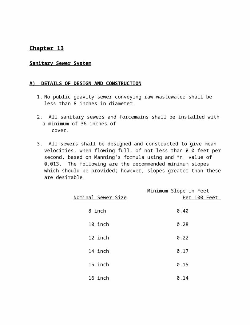
2. Federal Specifications and Standards (FSS):
J-C-30A(1) Cable and Wire, Electrical
(Power, Fixed Installation)
W-C-375B Circuit Breakers, Molded Case;
Branch Circuit and Service.
W-C-586C Conduit Outlet Boxes, Bodies
And Entrance Caps, Electrical:
Cast Metal.
W-C-596E/GEN(1) Connector, Plug, Receptacle and
Cable Outlet, Electrical Power
(Supplement 1a).
W-C-1094A Conduit and Conduit Fittings,
Plastic, Rigid.
W-F-406B Fittings for Cable, Power,
Electrical and Conduit, Metal,
Flexible.
W-F-408C(1) Fittings for Conduit,
Metal, Rigid (Thick Wall and
Thin-Wall (EMT) Type).
W-P-455A(6) Plate, Wall, Electrical.
W-S-610C(1) Splice, Conductor.
HH-I-510D Insulation Tape, Electrical,
Friction.
HH-I-553C(1) Insulation Tape, Electrical
(Rubber, Natural, and Synthetic).
HH-I-595C Insulation Tape, Electrical,
Pressure Sensitive Adhesive,
Plastic.
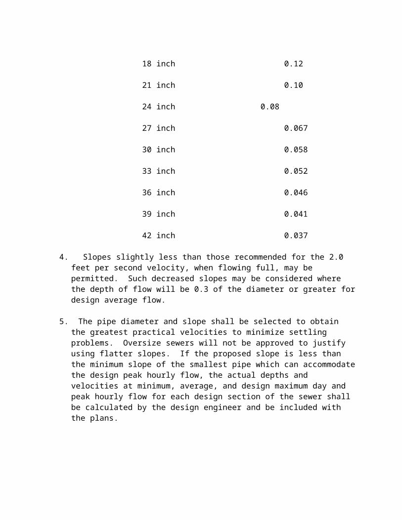
WW-C-581E Conduit, Metal, Rigid, and
Intermediate; and Coupling, Elbow, and Nipple
Electrical Conduit: Steel Zinc-Coated.
3. Institute of Electrical and Electronics Engineers (IEEE):
117 Test Procedure for Evaluation of Systems of
Insulating Materials for Random-Wound AC
Electric Machinery.
4. National Electrical Manufactures Association (NEMA):
ICS-1 Industrial Controls and Systems.
MG 1 Motors and Generators.
WD 1 General Purpose Wiring Devises.
TC -2 Electric Plastic Tubing (EPT) and Conduit (EPC-
40 and EPC-80).
TC-3 PVC Fittings for Use with Rigid PVC Conduit and Tubing
5. National Fire Protection Association (NFPA):
70 National Electrical Code (NEC).
6. Underwriter’s Laboratories, Inc. (UL):
50 Electrical Cabinets and Boxes.
83 Thermoplastic-Insulated Wires and Cables
498 Electrical Attachment Plugs and Receptacles.
508 Electric Industrial Control Equipment.
514B Fittings for Conduit and Outlet Boxes.
514C Non-Metallic Outlet Boxes, Flush-Device Boxes and Covers.
651 Schedule 40 and 80 PVC Conduit.
886 Outlet Boxes and Fittings for Use in Hazardous (Classified)
Locations.
1449 Transient Voltage Surge Suppressors.
1660 Liquid-Tight Flexible Non-Metallic Conduit, Electrical.
B. Install electrical equipment and materials to meet requirements of national and
local
electrical codes.
1.4 SUBMITTALS
A. The Contractor shall submit a complete list of materials and equipment to be
incorporated in the work to the Engineer within 30 days after the Award of Contract or
at least 30 days prior to ordering materials for a developer project.
B. The list shall include catalog numbers, cuts, sheets, diagrams and other descriptive data
required to demonstrate conformance to the specifications. Partial lists will not be
acceptable.
C. The basis of approval shall be the manufacturer’s published ratings for the equipment.
Manufacturer shall be regularly engaged in manufacture of products specified.
1.5 SHOP DRAWINGS
A. Shop drawings shall be submitted to the city for the following items of equipment:
1. Main Service Disconnect
2. Control Panel and Components
3. Generator Receptacle
4. Transient Voltage Surge Suppressor
5. Junction Box
6. Conduit and Fittings
7. Alarm Light/Horn and Silence Switch
8. BIRD CAGE PRESSURE TRANSDUCER
9. Float Switches
10. RTU, Antenna and Mast
B. Contents of the shop drawings must include the following:
1. Details of construction
2. Dimensions
3. Materials
4. Finish
5. Ratings
6. Accessories
7. Trim
8. Ladder type schematic control diagrams and wiring diagrams.
1.6 MANUFACTURER’S LITERATURE:
A. Manufacturer’s literature shall be submitted for the equipment listed in
Paragraph 1.5
above, including the following:
1. Written description of equipment function, normal operating characteristics and
limiting conditions.
2. Recommended assembly, installation, alignment, adjustment, calibration and
operating instructions.
3. Maintenance instructions.
4. Parts list with identification to assembly drawing.
1.7 CERTIFICATION/DOCUMENTATION
A. Transient voltage surge suppressor submittals shall include the following:
1. UL 1449 clamp voltage documentation.
2. Category C3 clamp voltage test results.
1.8 OPERATION AND MAINTENANCE MANUAL
Prior to final acceptance of this project, three operation and maintenance manuals shall be
submitted to the Engineer. The manual shall include manufacturer’s literature as outlined in
1.6 above, drawings corrected per shop review comments, as-built modifications and list of
suppliers and/or service shops which can provide parts and accessories and equipment repair
for the items of the equipment listed in Paragraph 1.5 above. The lists shall include a contact
name, telephone number and address.
1.9 DELIVERY, STORAGE AND HANDLING
Deliver materials with manufacturer’s tags and labels and UL labels intact. Deliver packaged
material in manufacturer’s original, unopened containers bearing the manufacturer’s name,
brand and UL label. Store material and equipment in a dry, clean location. Handle and store
so as to avoid damage. Remove items delivered in broken, damaged, rusted or unlabeled
condition from the project site immediately.
1.10 WARRANTY
All equipment and materials supplied shall be warranted against defective design, materials
and workmanship for a minimum period of one year, or as specified herein, against normal
use. The warranty period shall begin once the total project is accepted by the City and shall
cover replacement of equipment and/or repair including labor, travel time and miscellaneous
expenses at no cost to the City for the full warranty period.
2.0 PRODUCTS
2.1 MATERIALS AND EQUIPMENT
A. All materials and equipment shall be new, approved and labeled, where required, by
Underwriter’s Laboratories, Inc.
B. Where two or more units of the same class of equipment or materials are required,
provide all units from a single manufacturer.
C. Provide materials and equipment of suitable composition to perform satisfactorily when
exposed to corrosive conditions of project site.
2.2 CONDUIT
A. Rigid Steel Conduit: Rigid steel conduit shall be zinc coated and shall conform to FSS
WW-581E. Fittings shall be cast or malleable iron, zinc-coated, and shall conform to
FSS W-C-586C and UL 514B. Seal fittings shall conform to the requirements of NFPA 70
(NEC) for Class 1, Group C & D, and UL 886.
B. Rigid Non-metallic Conduit: Non-metallic conduit shall be polyvinyl chloride
compound and shall conform to NEMA Specifications TC-2, FSS W-C-1094A and UL
651. Conduit shall be sunlight resistant, rated for use with 90°C conductors. Fittings
shall be of the same polyvinyl chloride compound, of the same manufacturer as the
conduit and shall conform to NEMA Specification TC-3, FSS W-C-1094A and UL
651. Conduit and fittings shall be joined by means of a solvent cement of the same
manufacturer as the conduit. Type of cement and procedure for application shall be as
recommended by the manufacturer. Conduit shall be Carlon Plus 40 and Plus 80 or
approved equal.
2.3 BOXES
A. Junction Boxes: Junction boxes shall be gasketed NEMA 3R stainless steel and shall
be sized as recommended by the NEC or shown on the drawings.
2.4 WIRING DEVICES
A. Receptacles: Duplex receptacles shall conform to FSS W-C-596E/GEN(1), NEMA
WD-1 and UL 498, shall be a ground fault circuit interrupter type, rated twenty
amperes (20) 125 volts A.C., two pole, three wire, grounding type with non-breakable
nylon face plate. Receptacle shall have test and reset buttons accessible on the face.
Receptacle shall be Russell Stohl 3134-72 for compatibility with auxiliary generators.
2.5 DEVICE PLATES
A. Cover Plates: Cover plates shall be satin finish stainless steel and shall conform to FSS
W-P-455.
2.6 WIRE AND CABLE
A. Conductors: All conductors shall be annealed soft drawn copper, conforming to the
latest ASTM Specifications, FSS J-C-30A(1), UL 83 and the latest requirements of the
NEC. All conductors shall have THW or THWN type insulation, rated at 600 volts,
unless specifically noted otherwise.
1. Other types of insulation may be used as permitted by the NEC. The Contractor
shall be responsible for change in conduit size and conductor size to maintain
ampacity of circuit.
2. Wire #8 AWG and larger shall be stranded cocentric lay. Wire sizes #14, #12 and
#10 AWG shall be stranded for control and motor power and solid for all other
uses.
3. Conductors shall as manufactured by Senator Wire and Cable Company, Laribee
Wire Manufacturing Company, Inc., Southwire Company or approved equal.
B. Conductor splices shall conform to FSS W-S-610C(1). Acceptable:
Scotchcast Splicing Kit, Minnesota Mining and Manufacturing Co. or approved equal.
Friction tape shall conform to FSS HH-I-510D. Rubber tape shall conform to FSS HH-
I-553C(1). Plastic tape shall conform to FSS HH-I-595C.
2.7 MOTORS
A. Motors shall be provided with equipment driven, and shall conform to the latest
applicable requirements of NEMA, IEEE, ANSI and NEC standards.
B. Motors larger than one half (½) horsepower shall be NEMA design B suitable for
continuous duty operation. Motors shall be rated 208 volts for a 208 volt system, 230
volts for a 240 volt system and 460 volts for a 480 volt system. All motors shall be 3
phase with 3 phase service provided by the power company. All of the stations requires
back up generators for information regarding generators. Look at Technical
Specification on page 17-1.
C. Motors shall be provided with class F non-hygroscopic insulation system utilizing
materials and insulation system evaluated in accordance with IEEE 117 classification
tests. Temperature rise shall be a maximum of (80)°C. by resistance at a service factor
of 1.0 in an ambient temperature of forty (40)°C. Motors shall have multiple dips and
bakes of varnish treatment for additional protection.
D. Motor current and torque shall be in accordance with NEMA MG1-12.34, and 12.37.
E. Motors shall be furnished with a minimum service factor of 1.15 and shall be selected
for operation within their full load rating without applying the service factor.
F. Motors shall be suitable for full voltage across the line starting.
G. Motors shall be equipped with ball, open, single row, deep groove Conrad type
bearings conforming to the Anti-Friction Bearing Manufacturers Association Standard
20.
H. Submersible motors shall have power and control conductors housed in multi-
conductor cables of sufficient length to reach first junction box as shown on drawings.
Cable entrance to motor shall be sealed. Motors shall be explosion-proof and shall meet
the requirements of the NEC for Class I, Division I, Group D, hazardous locations.
I. Motors shall be capable of the number of starts per hour required by the pumping
sequence without overheating or causing damage to the motor. Six (6) starts per hour
capability shall be the minimum.
J. Motors shall be provided by one of three manufacturers and should only be substituted
when design criteria can not be met by any one of the three manufacturers. Substitution
shall only occur when approved by the City Engineer prior to the submittal process.
1. Flyght
2. Davis EMU
3. Ebara
2.8 PUMP CONTROL PANEL
A. General: The electrical equipment and pump control system shall be mounted within a
gasketed NEMA 3R stainless steel enclosure with 3 point latch and provisions for pad
locking. The control compartment shall incorporate a dead front inner door, mounted
on a continuous hinge on one side and secured on the opposite side with thumb screws
or ¼ turn fasteners, and a removable back panel, secured to the enclosure with the
collar studs, on which components shall be mounted. The dead front inner door shall be
clear lexan. The back panel shall be aluminum. The control panel shall be painted
white enamel and sized to prevent excessive heat build-up. The control panel may be
mounted in direct sunlight.
1. All power and control components shall be securely fastened to the removable
back panel with stainless steel screws and lock washers. Switches, indicators and
instruments shall be mounted through the control panel inner door. Provide cut-
out in dead front inner door for pump control unit per the manufacturer’s
recommendation. Self-tapping screws shall not be used to mount any components.
Control voltage components shall be segregated from line voltage components.
All connections from the back panel to door mounted or remote devices shall be
made through terminal blocks.
2. A main terminal block and ground lug shall be furnished for field connection of
the electrical supply. The connections shall be designed to accept copper
conductors of sufficient size. The main terminal block shall be mounted to allow
incoming wire bending space in accordance with Article 373 of the National
Electrical Code (NEC). Separate terminal strips shall be provided for 120 volt
circuits, one for single phase power and one for telemetry outputs. The 120 volt
terminal blocks shall be segregated from the main terminal block.
3. Properly sized circuit breakers shall be furnished for the main service disconnect,
generator disconnect and each of the pump motors. Handles for the circuit
breakers shall extend through the dead front inner door. The main service and
generator circuit breakers shall be provided with a mechanical interlock as
indicated on the drawing.

4. An open frame, across the line, NEMA rated magnetic motor starter shall be
furnished for each of the two pump motors. An overload reset button shall be
mounted through the dead front inner door in such a manner as to permit resetting
the overload relays without opening the door.
5. Indicating lights shall be furnished as indicated on the drawing. Lamps shall be
replaceable from the front without opening the dead inner door and without the
use of tools.
6. A control power transformer shall be provided for 480 volt systems. Control
voltage shall be 120 volts AC and shall be fused on the primary and secondary
underground conductors.
7. Provide a back-up phase failure relay as indicated on the drawings. The relay
shall be solid state and monitor all three phases. Contacts shall be isolated DPDT.
Relay shall be Square D Class 8430 or approved equal.
B. The pump control unit (TCU) shall be a microprocessor-based multi-pump controller
module designed for use with the telemetry systems. As a minimum the TCU shall have
the following features:
1. Local automatic control from float, bubbler, transducer, or ultrasonic inputs. All
the electronics for each type of input shall be included in the TCU.
2. Local manual control provided by HOA switches. The HOA switches shall be
fail safe and operate in the OFF and HAND position without power. HOA Switch
Alarms shall be reported back to central site computer. Alarms shall indicate that
an HOA switch has been left in the HAND or OFF position.
3. Remote control from the central site computer shall provide individual pump
overrides and disables, station and alarm disables.
4. Triplex/Duplex/Simplex configurable. The module shall have the capability of
being configured for one, two or three pumps.
5. Pump alternation function shall be provided. Alternation around non-operational
pumps shall be provided.
6. An on-board 240 VAC three phase phase monitor shall be provided. The phase
monitor shall be transformer-isolated and detect loss of phase, phase reversal, low
phase and high phase faults. All phase monitor adjustments shall be adjustable
from the keyboard or keypad. Phase voltages from phase A to B and from phase
A to C shall be transmitted to the central site computer.
7. The TCU shall be easily replaced by removing two industry standard terminal
connectors.
8. Alarm light and bell outputs capable of driving 120 VAC loads to 1 amp.
9. Local input for alarm silence switch.
10. Remote alarm bell and light disable from the central site computer.
11. Transducer alarm reporting back to the central site computer when set points are
operating out of sequence. In the set point mode each set point position shall be
transmitted to the central computer.
12. The TCU shall utilize a 16 character display to provide the operators with the
elapsed run time of each pump, the average run time of each pump, the flow of
each pump, the flow of the station and the time of day.
13. Pumps/Check Valve/Breaker Fault alarms shall be reported back to central site
computer. The alarms shall be activated when a pump is called to run, but fails to
run, or if the pump is turned off by the TCU, but continues to run.
14. Pump run status shall be reported back to central site computer. Pump run times
shall be reported within 2 second accuracy.
15. Configuration parameters shall be adjustable through the front mounted keypad or
a RS-232 service port.
16. Redundancy of level sensing devises shall be supported.
17. All inputs and outputs shall be optically or magnetically isolated and surge
suppressed.
C. Pump Control System: The lift station pumps and level controls shall be operated by a
TCU manufactured by Data Flow Systems, Inc., with no substitutions permitted. The
control system shall automatically control the lift station pumps with built-in
alternation, pump start time delay, and high and low alarms. The systems shall use a
Bird Cage Pressure Transducer level sensor, manufactured by Blue Ribbon, Inc. (no
substitution), with pressure switches as backups.
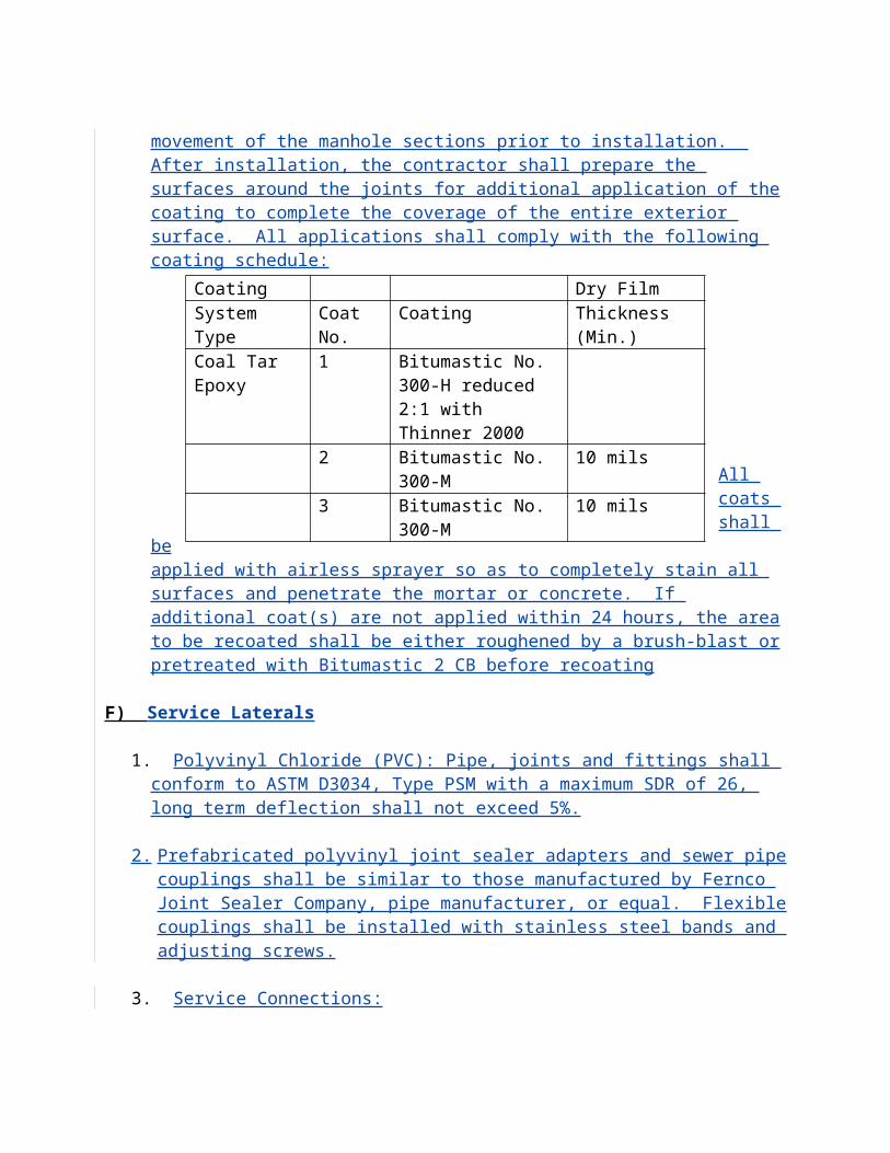
1. The control systems shall be a complete duplex control system and shall
automatically control two pumps in response to the Transducer measurement
system. It shall provide high and low level alarms and full SCADA support. If
failure is experienced in the primary level sensor, the system shall automatically
switch to the backup pressure switches.
2. The systems shall control the pumps in a lead/lag mode with turn on and turn off
points for each pump individually settable from the front panel. Each pump shall
have an external disable input which can be connected to fail sensors in the
pumps. High and low level alarms shall be provided with setpoints settable from
3. the front panel, and shall be automatically disabled for the first 10 seconds after
power-up to permit the level sensing system to stabilize. A time delay or dead
band shall be provided for pump starts.
4. The primary level sensor shall be complete with Bird Cage pressure transducer,
industrial housing, 2-wire loop driven type current transmitter and intrinsic
barrier. Sensor shall be installed in a 4” diameter Schedule 40 PVC stilling pipe
as recommended by the sensor manufacturer.
D. Motor Starters: Magnetic motor starters shall be rated in accordance with NEMA
Standards, sizes and horsepower ratings and shall be full voltage non-reversing type.
1. Magnetic starters shall be equipped with double break silver alloy contacts. All
contacts shall be replaceable without removing power wiring or removing starter
from panel.
2. Coils shall be of molded construction. All coils shall be replaceable from the front
without removing the starter from the panel.
3. Overload relays shall be the melting alloy type with a replaceable control module.
Thermal units shall be of one-piece construction and interchangeable. The starter
shall be inoperative if the thermal unit is removed. Three-phase starters shall have
overload relays in all three phases. Reset button shall be accessible without
opening dead front panel. Visible trip indication for overload with phase
indication shall be provided. Relay shall have a form C contact which operates
when the overload relay trips, contacts shall be wired to terminal blocks for use in
remote control panel.
4. Starter shall be suitable for the addition of at least four (4) external electrical
interlocks of any arrangement, normally open or normally closed. Starters shall
be supplied with a minimum of two (2) interlock contacts.
5. All magnetic starters shall be provided with terminal blocks for wiring of devises
external to starter enclosure.
6. Starter shall be capable of starting the motor the number of times per hour
required by the pumping sequence without causing damage to the starter.
7. Starters shall be sized one size above required designed to enable future upgrades.
8. Soft start must be used on any motor 25hp or over.
9. Any station with three (3) or more pumps must have VFD.
E. Control Devises.
1. Pilot lights shall be incandescent type with red lens. Pilot lights shall be Square
D, Type “K” or equal.
2. Control relays shall be 8 pin track mounted socket type as manufactured by
Square D company or approved equal.
F. Circuit Breakers
1. Provide molded case thermal magnetic circuit breakers as indicated on the
drawings. Circuit breakers used as service entrance disconnects shall be suitable
and rated as service entrance equipment.
2. Circuit breakers shall be of single unit construction and multi-pole circuit
breakers shall have trip elements in each pole with common trip bar. Frame size
225 amp and larger shall have adjustable magnetic instantaneous trip. Frame size
400 amp and larger shall have interchangeable thermal magnetic trip units.
3. Circuit breaker interrupting ratings shall be equal to the available short circuit
current at the point of installation with the minimum ratings as follows:
Frame Size 240V 480V
100 Amp 18,000 14,000
225 Amp 25,000 22,000
400 Amp 42,000 30,000
800 Amp 42,000 30,000
1200 Amp 42,000 30,000
2.9 RADIO TELEMETRY SYSTEM
A. Scope: Lift stations are to be connected by a radio transmission link. The central site
will acquire data from the remotes, report status and provide data logging capability.
The remote stations shall monitor and transmit status on request. Control functions
shall be implemented by commands from the central site which shall be interpreted and
initiated by the remote stations.
B. Remote Terminal Unit: The remote terminal unit (RTU) shall be a microcomputer-
based data collection and dissemination subsystem. The RTU shall communicate with
the central site via a two-way radio link. The RTU shall be designed to accommodate
plug-in function modules. Function module card connectors shall be gold-over-nickel
plated to inhibit corrosion. The system shall be capable of being outfitted, at any time,
with RTUs capable of being configured with up to fifteen (15) function modules per
RTU, with no software or firmware changes to the system. All sheet metal utilized
inside the enclosure must be anodized. Any RTU shall have the capability of being
utilized as a digipeater for relaying massages from the central site computer to any
other RTU. The response messages from the destination RTU shall be digipeated to the
central site computer by the same RTU which forwarded the message to the destination
RTU. An interlock system shall be provided to prevent the removal of function
modules with the power applied. The RTU shall support a local serial interface. The
local serial interface shall provide local access to all the functions of the RTU. The
local serial interface shall support the monitoring of the radio communications link.
The RTUs shall be enclosed in a NEMA 4X, 316 grade stainless steel enclosure,
painted white and shall be mounted on the antenna mast. The RTUs shall be
manufactured by Data Flow Systems, Inc. of Melbourne, Florida.
C. Function Modules: The function modules shall be designed so they do not have
configuration switches or straps and may be easily added in the future. The function
modules must be designed with surge suppression on all inputs and outputs. The
function module card edge connector fingers shall be gold-over-nickel-over-copper
plated to inhibit corrosion. Replacement of a function module shall not require the use
of tools or the removal of any interface wires. There shall be no components associated
with the function module mounted to the motherboard (passive backplane).
D. Radio Interface Module: Each RTU shall require one radio interface module. This
Module shall control the terminal radio during the polling sequence. In the event of
transmissions of more than 10 seconds this module shall shut down the transmitter.
This protection function shall be implemented in hardware. Firmware implementation
will not be acceptable. The radio interface module shall have a service port to provide
communcations link monitoring. The service port shall also provide the capability to
directly monitor and/or control each module in the RTU. The radio interface module
utilized at the RTUs shall be interchangeable with the radio interface module at the
central site. The systems shall be capable of utilizing up to 250 radio interface modules
per communications link and up to 15 function modules per radio interface module. All
communications shall be in ASCII and utilize an error in detecting and correction data
transfer protocol. Communications between the central site and the RTUs shall have a
minimum speed of 1200 bits/second. Each radio interface module shall have a radio
transceiver mounted to it. The radio shall be an FM transceiver which operates in the
450 MHz to 475 MHz frequency range.
E. Transmitter Specifications:
RF POWER OUTPUT: ADJUSTABLE FROM 2.0 TO 5.0SPURIOUS OUTPUT: -60 dBc MAX HARMONIC OUTPUT:
-50 dBc MAX FREQ. STABILITY:+/-5 PPM
MODULATOR DEVIATION: ADJUSTABLE TO 5 kHzFREQUENCY RESPONSE: FLAT +/-2.0 dB
FROM 50 Hz TO 10kHz
TOTAL HARMONIC DISTORTIOB: 5% MAXFM HUM NOISE: -50dB MAXCARRIER ATTACK TIME: 50 mSec
F. Receiver Specifications:
SENSITIVITY: 0.35 µV MAX FOR 10 dB S+N/NQUIETING: 20 dB QUIETINGSIGNAL PRESENT THRESHOLD: 0.4 µ V+/-3dBINTERMODULATION: -18 dBm TYPICAL THIRD ORDER INTERCEPTIF SELECTIVITY: 6 dB BW=+/-7.5 kHz MIN
60 dB BW = +/-25 kHz MAXTOTAL HARMONIC DISTORTION: 4% MAXFREQUENCY STABILITY: +/-10 PPM
G. Analog Monitor Module: The analog monitor module shall monitor up to 4 analog
inputs. The analog monitor module shall be capable of accepting 4-20 ma or 0-5 Vdc
on each of the inputs. The analog input shall have 12 bit accuracy. The analog monitor
module shall have support-configuration reporting granularity and alarm thresholds.
The configuration parameters shall be downloaded over the radio link from the central
site computer. All the analog monitor module-configurable parameters shall be
operator-controlled. The analog monitor module shall have four (4) qualifier inputs to
prevent alarms during conditions when alarms are not valid. The analog monitor
module shall be LEDs to indicate: the status of each qualifier input point; receive
communications; transmit communications; CPU fault; and power status. Software or
firmware modifications to support the configuration will not be accepted.
H. Power Supply: All function modules in the RTU shall run off dc voltage from +7.5
volts to +13 volts. The power supply module shall supply +12 volts. A battery backup
shall be provided to operate the system a minimum of 120 minutes in event of power
failure. The power supply shall be surge protected. The power supply shall be short
circuit protected by current limiting. Normal operation shall automatically resume
when the short circuit overload is removed. The power supply shall be sized to operate
the system with the battery removed. The power supply module shall provide a battery
packed, isolated bias voltage source. The isolated bias voltage source shall be utilized
to monitor the high well alarm so as to make sure the alarm is detected and reported
during power outages. The circuit breaker for the power supply module shall be part of
the power supply module. Neither the use of tools nor the disconnection of any wires
shall be required to remove the power supply module.
I. Batteries: The remote terminal shall have the uninterruptible power source function
built in. The power supply will keep batteries at a float charge. The batteries shall not
be damaged by deep discharges.
J. Antenna Subsystem: An 11.5 gain directional antenna shall be used to transmit and
receive data at the RTU. It shall be supported on a mast/pole and have dc grounding
for lightning protection. The antenna mast/pole shall be hot dipped galvanized for
corrosion protection. All mounting hardware shall be made of stainless steel. The mast
shall meet or exceed the quality and reliability of the AG20 manufactured by Rohn.
The coax cable shall be the type that utilizes an inert semi-liquid compound to flood the
copper braid. The coax cable shall meet or exceed the quality, reliability and
performance of VB-8 manufactured by DB Products, Inc of Dallas, Texas. Type N
connectors shall be utilized at both ends of the coax. The type N connectors shall be
sealed with 3 inch sections of Alpha FIT321-1-0 sealant shrink tubing. The coax shall
be secured to the mast/pole with E.V.A.–coated 316 stainless steel cable ties. The cable
ties shall meet or exceed the quality, reliability and performance of AE112 cable ties
manufactured by Band-It. The antenna shall be constructed with heavy-wall tubing
elements and large, rugged-machined aluminum blocks for the boom-to-element
junctions. The antennas shall meet or exceed the quality, reliability and performance of
the PLC-4510N manufactured by Cushcraft/Signals of Manchester, New Hampshire.
K. Enclosures: RTUs shall be housed in NEMA 4X316 stainless steel enclosures, acid-
dipped and painted white. Enclosures shall be sized to accommodate the plug-in
modules needed to meet the requirements, plus at least one additional module for
expansion. All mounting hardware utilized shall be stainless steel. The enclosure shall
be capable of being locked. The enclosures shall be offered in four configurations.
1. An enclosure that will accommodate a radio and two functions modules.
2. An enclosure that will accommodate a radio and four functions modules.
3. An enclosure that will accommodate a radio and six functions modules.
4. An enclosure that will accommodate a radio and 15 function modules.
L. Alarm processing Program (for information only): Alarm conditions shall automatically
be brought to the operator’s attention audibly and visually on the central site video
terminal by the alarm processing program. The video terminal shall have a reserved
section for alarm display. The microcomputer shall queue alarm messages if there is
not sufficient space available to display them in the reserved area. As alarms are
acknowledged by the operator, the microcomputer shall display the next sequential
alarm message until all alarms are acknowledged. The audible alarm shall sound until
all alarms are acknowledged.
M. Service: The system supplier shall offer full factory support of the installed system
through the use of factory employees. Service representatives who are not direct
employees of the system supplier, or who are not specifically trained in the service of
the radio telemetry systems shall be unacceptable. The customer shall have 24 hour per
day access to service personnel through the use of a pager.
N. Warranty: The system supplier shall warrant all hardware and software provided under
this contract against all defects in material and workmanship for a period of one year.
The system supplier shall warrant the telemetry software to be free of defects for as
long as it is operational. The system supplier shall also provide free updates to this
software for the life of the system. The function modules utilized in the RTUs shall
carry an additional two (2) year return-to-factory warranty. The two year return-to-
factory warranty shall also cover damage due to lighting.
2.10 GROUND RODS
Ground rods shall be copper-clad steel, 5/8”x8’ sectional type, with couplings and driving
studs for installation. Connection of grounding conductors to ground rods shall be
exothermic welded; compression lug connectors shall not be used.
2.11 TRANSIENT VOLTAGE SURGE SUPPRESSOR
A. The transient voltage surge suppressor shall be listed in accordance with UL 1449.
Suppressor shall meet or exceed the following criteria:
1. Single impulse current rating of 80,000 amperes minimum per phase (8/20 µsec.
waveform).
2. Pulse life rating of 1000 occurrences with no clamping drift for Category C (8/20
µ sec. waveform).
3. UL clamping voltage shall not exceed the following:
Voltage L-N N-G
120/240 500 500
4. The suppressor shall have external fuse or circuit breaker protection.
B. Minimum requirements for surge suppressor:
1. Provide suppression elements between each phase and the system neutral and
between the neutral conductor and ground.
2. Suppressor failure mode shall be of a “fail-short” design.
3. Visible indication of proper connection and operation shall be provided.
4. Mounting position shall be selected to provide shortest lead possible between the
suppressor and point of connection.
5. Turn-on and turn-off times shall be less than one nanosecond.
6. Suppressor shall be of solid-state componentry and shall operate bi-directionally.
7. Suppressor shall have a five-year warranty guarantee period.
C. The transient voltage surge suppressor shall be installed in accordance with the
manufacturer’s installation instructions.
D. Acceptable Manufacturer: Advanced Protection Technologies, Inc., Leviton or
approved equal.
2.12 SAFETY SWITCH
A. Safety switch shall be NEMA heavy-duty type HD and be UL listed. Switch shall be
rated for use as service equipment.
B. The switch shall have switch blades which are fully visible in the OFF position when
the door is open. Switch shall have permanently attached arc suppressors hinged or
otherwise attached to permit easy access to line-side lugs without removal of the arc
suppressor. Lugs shall be UL listed for copper and aluminum cables and front
removable. All current-carrying parts shall be plated by electrolytic process.
C. The switch shall be have a quick-made and quick-break operating handle and
mechanism which shall be an integral part of the box, not the cover. Padlocking
provisions shall be provided for padlocking in the OFF position only, with at least three
(3) padlocks. Switch shall have a dual-cover interlock to prevent unauthorized opening
of the switch door in the ON position or closing of the switch mechanism with the door
open.
D. The switch shall be furnished in a code gauge NEMA 4X 316 stainless steel enclosure.
2.13 FLOAT SWITCHES
Float switches shall be a single-pole, direct acting, NC or NO as required and shall be
suitable for suspension or pipe mounting within the lift station wet well. Float switches shall
be a non mercury Solo-Float type D or approved equal.
3.0 EXECUTION
3.1 LAYOUT OF CONDUIT AND WIRING SYSTEMS
The contractor shall lay out the work and be responsible for all necessary lines, levels,
elevations and measurements. The drawings indicate extent and general arrangement of the
components. The contractor shall become familiar with the work of other trades involved in
the construction. Exact routing of raceways and locations of equipment shall be governed by
structural conditions and obstructions. This Contractor shall coordinate with the equipment
shop drawings for locations of equipment to be connected as furnished by others. This is not
to be construed to permit redesigning systems.
3.2 INSTALLATION
A. General: Comply with National Electrical Code, National Electrical Safety Code, local
codes and rules and regulations of local agencies having jurisdiction. Size of
conductors, circuit breakers, motor controllers and protective devices indicated or
specified shall meet all requirements of the NEC.
1. Determine rating and type of all electrical equipment furnished. Provide electrical
equipment and conductors of correct size to serve equipment. Voltage drop shall
be limited to 3%, including main service, feeder and branch circuit. Coordinate
electrical installation of systems and packaged equipment furnished by other
disciplines.
2. Provide coordination of protective, control and signaling devices.
B. Grounding: Solidly ground all non-current-conducting metal parts to the electrical
installation grounding bus. A green insulated grounding conductor shall be carried with
each circuit.
1. Provide common grounds throughout system.
2. Provide a ground grid consisting of driven copper clad steel ground rods
connected by bare copper conductor at service entrance and/or as shown on the
drawings. Resistance shall be 10 ohms or less before connection to system.
C. Identification: Equipment such as, but not limited to: disconnect switches, motor
starters, control panel, etc. shall be clearly marked.
1. Identify all devices operating at more than 250 volts phase-to-phase, or 125 volts
phase-to-ground, with red enamel letters or numerals of appropriate height
applied with a stencil.
2. Except as otherwise noted, all equipment shall be marked with engraved
nameplates of laminated two-color phenolic plastic having white letters. Attach
each nameplate with stainless steel screws. Align nameplates on equipment being
marked in center near the top.
3. Conductors shall be identified at each termination, pull box, junction box, point of
entry to or exit from wireways, control panel, and other points of access. Tags or
labels shall be securely affixed to the conductor in visible locations. Tags shall be
durable plastic with the designation stamped on one side with suitable dies.
Labels shall be permanent with legible black characters on white head-shrink
tubing or equivalent identification acceptable to the engineer. Power conductors
shall be color-coded to identify phases, neutral and switching legs, using plastic,
self-sealing tape. Control conductor (including monitor and instrumentation
conductors) shall be identified by color coding and tag or label as to wire number
(corresponding to manufacturer’s and City’s wiring diagram) and equipment
name.
4. All wiring within control panel shall be enclosed in wiring duct. Minimum
spacing between duct and other components shall be 2”.
D. Conduit
1. Rigid galvanized steel (RGS) conduit shall be used above grade and for wiring
within Class I, Division I locations.
2. Rigid non-metallic Schedule 80 (PVC) conduit shall be used below grade.
3. Conduit burial depth shall be measured from top of conduit to undisturbed grade
and shall be 18 inches (minimum) below unpaved areas and slabs on grade and 24
inches (minimum) below stabilized subbase in paved areas.
4. Where conduits rise through slabs on grade, curved portion of bends shall not be
visible above finish slab. Galvanized conduit in concrete or exposed within the
wetwell shall be PVC coated.
5. Avoid bends and offsets, where possible. Make bends and offsets with an
approved hickey or conduit bending machine. Do not install crushed or deformed
conduit. Use expansion fittings or other approved devices where conduit or
tubing crosses expansion joints. Prevent dirt or trash from lodging in conduits,
boxes and fittings. Free clogged conduit of all obstructions or replace conduit.
6. Conduit connections exposed in wet locations shall be made by watertight
threaded hub. Metallic conduit box connections may use a two-piece hub with
built-in recessed neoprene gasket such as Appleton Uni-Seal. Non-metallic
conduit box connectors may use neoprene flat washer or “O-ring placed over
threads of the fitting between the shoulder of the fitting and the box. Conduit
connections shall maintain NEMA rating of enclosures.
7. All conduit shall be increased to the next larger trade size above the minimum
size required, to enable future upgrades, when possible.
E. Wiring
1. Provide complete system of conductors as indicated.
2. Size shall be as required by the NEC and shall be No. 12 AWG minimum for
power and lighting circuits, and No. 14 AWG minimum for control and alarm
circuits.
3. Crimp on insulated wire terminals shall be used on stranded wire for terminations.
3.3 FIELD TESTS AND OBSERVATION
A. General: Do not enclose or cover any work until it has been observed and tested by the
Owner’s representative.
1. Provide all personnel, equipment and instruments required for observation and
testing
2. Show, by demonstration, that all circuits and devices are in operating condition.
3. Notify Engineer one (1) week prior to test date.
B. Ground Rod Test: Before any wire is connected to ground rods, test each rod for
resistance to ground.
1. Testing instrument shall be a direct reading, single test, portable ground testing
megger.
2. Test procedure shall be as recommended by test instrument used.
3. The make and model of test instrument used and a copy of test procedure shall be
submitted to the Engineer before test is conducted.
4. Do not conduct tests within 48 hours after rainfall or during foggy weather.
5. If ground resistance exceeds 10 ohms, additional grounds shall be driven.
6. The grounding test shall be witnessed by the Engineer or a representative of the
City. A copy of test results and method shall be included in the maintenance
manual. Deliver three copies of test results to the Engineer within one week after
test.
3.4 ADJUST AND CLEAN
A. Remove excess and waste materials from project site.
B. Remove defective work and replace with material that meets specification requirements
or repair to the satisfaction of the Engineer.
C. Touch up scratches, abrasions, voids and other defects in factory or shop finished
surfaces.
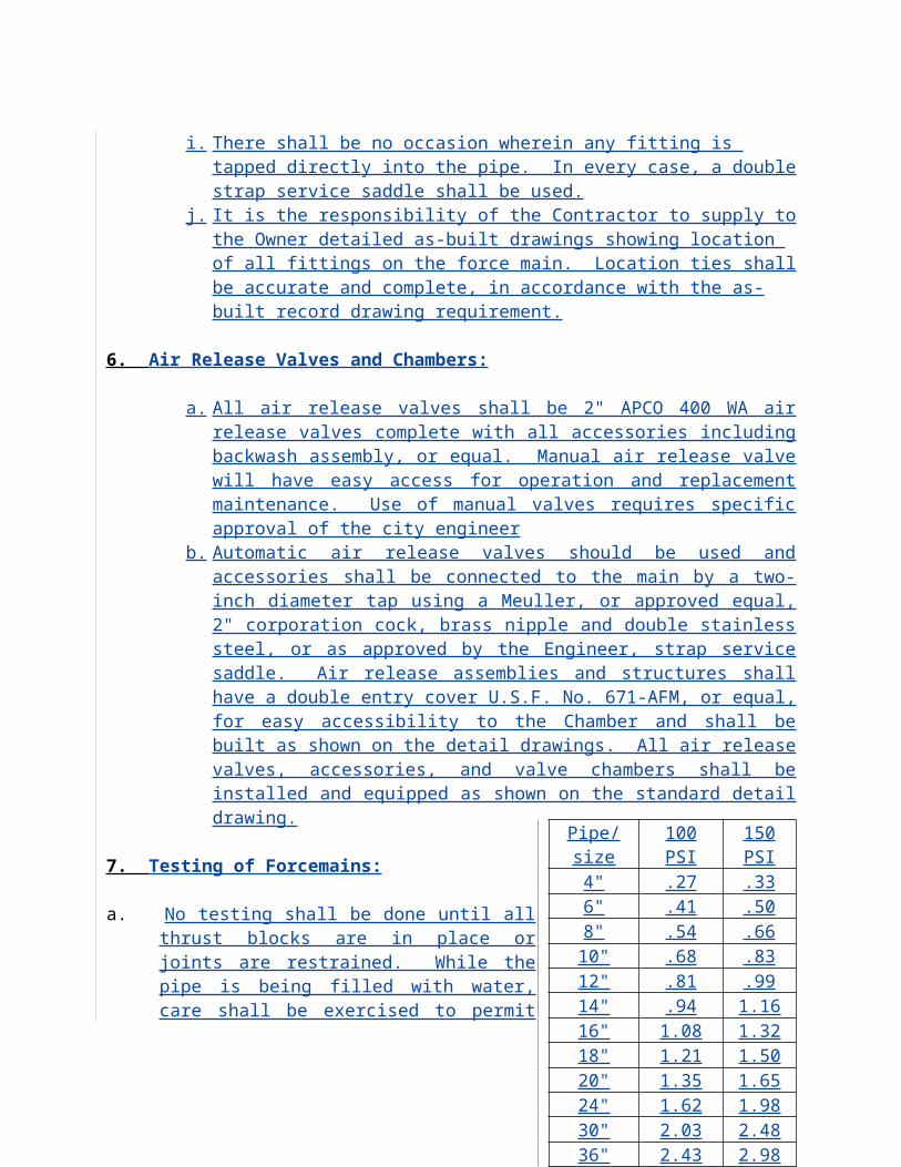
END OF SECTION
REQUIRED SUBMITTALS FOR PUMP STATIONS
Submittals shall be provided to the City in triplicate and include the following:
1) Shop and erection drawing showing all-important details of precast construction, dimensions and anchor bolt locations.
2) Precast coating specifications and warranty information.3) Descriptive literature, bulletins and/or catalogs of equipment.4) Data on the characteristics and performance of each pump. Data shall include guaranteed
performance of curves. Based on actual shop tests of similar units, which show that they meet the specified requirements for head, capacity, efficiency, submergence, and horsepower. Curves shall be submitted on eight and on-half (8 ½”) inch by eleven (11”) inch sheets, at as large a scale as is practical. Curves shall be plotted from no flow at shut-off head to maximum manufacturer recommended pump capacity. Catalog sheets showing a family of curves will not be acceptable.
5) Complete layouts, wiring diagrams, telemetry or control schematics, including coordination with other electrical control devices operation in conjunction with the pump control system. Suitable outline drawings shall be furnished for approval before proceeding with manufacture of any equipment. Standard reprinted sheets or drawings simply marked to indicate applicability may not be acceptable.
6) A drawing showing the layout of the pump control panel shall be furnished. The layout shall indicate all devices mounted on the door and in the panel and shall be completely identified.
7) The weight of each pump.8) Complete motor data shall be submitted including;
a) Nameplate identificationb) No-load currentc) Full load currentd) Full load efficiencye) Locked rotor currentf) High potential test datag) Bearing inspection report
9) All other data as required in this SECTION.
INSPECTION AND TESTING
A factory representative knowledgeable in pump operation and maintenance shall inspect and supervise a test run at the pumping station covered by this section. A minimum of one (1) working day shall be provided for the inspections. Additional time made necessary by faulty or incomplete work or equipment malfunctions shall be provided as necessary to meet the requirements in this section at no additional cost to the City. Upon satisfactory completion of the test run, the factory representative shall issue the required manufacturer’s certificate.
The test run shall demonstrate that all items of this section have been met by the equipment as installed and shall include, but not be limited to, the following test.
1) That all units have been properly installed.2) That the units operate without overheating or overloading any parts and without
objectionable vibration.3) That there are no mechanical defects in any of the parts.4) That the pumps can deliver the specified pressure and quantity.5) That the pumps are capable of pumping the specified material.6) That the pump controls perform satisfactorily.
WASTEWATER PUMP STATIONS NOT ACCEPTED BY CITY
All Owner and/or Developers who intend to construct wastewater pump stations that are ‘NOT ACCEPTED BY THE CITY’ yet intend to discharge into the City wastewater collection system shall make access available to the City for such stations in the event of an emergency. The City shall have the right to deny pump station discharge into its wastewater collection system if access to pump station is ever denied. Pump station discharge shall be by way of “single service” connection until tie in point with City system. Service connection to City wastewater collection system will have isolation valve installed per ‘Standard Drawings’ and ‘Specifications.’ Valve to be located at or close to owners’ property lines.
Pump station will be equipped with emergency generator and\or auxillary power connection. Pump station will be equipped with emergency pump by-pass connection compatible with the ‘City of Plant City Section L.9.2.-Pump By-Pass.’
Prior to date of acceptance of discharge into City collection system, owner will provide name, address and phone number of two persons or company responsible for all emergency responses to the facility. This will be a 24-hour per day, seven-(7) day a week response number. This information will be posted on the front exterior of the control panel by means of a permanent phenolic label.
INSTALLATION GUIDE
This section serves as ONLY AN AID to clarify what services and/or equipment is NORMALLY AND CUSTOMARILY furnished during the installation of a City accepted lift station. The Developer or Record is ultimately and solely responsible for the delegation and/or coordination or work, equipment and materials required to construct and install the lift station. The scope of work and materials/equipment provided is divided into five areas as follows:
Pump and Control Panel Supplier usually supplies the duplex submersible pump package and the associated control panel. This includes, but is not necessarily limited to, the following:
(2) submersible sewage pumps with flush valve and adequately sized motor cables
(2) discharge elbows with anchor bolts (2) sets of stainless steel guide rails and associated guide rail brackets (4) “Roto” floats and associated float brackets (1) set of aluminum hatch covers for wet well and valve vault (2) stainless steel lifting cable chain and associated hardware (1) control panel and component package which includes Data Flow Systems
Pump Control Unit (PCU) and unattached generator receptacle (1) start up services and manufacturer’s acceptance of pump and panel installation
as it pertains to pump and panel warranties (this includes all pertinent manuals and printed warranty information)
Telemetry System Manufacturer usually supplies and installs the telemetry panel and associated components which includes but is not necessarily limited to the following:
Telemetry control panel box Printed circuit cards Uninterrupted power source unit Radio unit set at required frequency Antenna with tower Electrical grounding components and connection between antenna and telemetry
panel Conduit and control wires between telemetry panel and lift station control panel Start up services and manufacturer’s acceptance of telemetry system as it pertains
to telemetry warranties (this includes all pertinent manuals and printed warranty information)
Subcontractor (electrical) usually, but not necessarily, supplies and installs the following:
Applicable electrical construction permits Stainless steel mounting rack for control panel and main disconnect Stainless steel Meter can and conduits as per TECO requirements Electrical and float conduits between control panel and wet well Connect motor cable and float cables to panel Control panel grounding system, (including connection to site fencing)
The Underground Contractor usually, but not necessarily, supplies and installs the following:
Wet Well (including all associated concrete invert work) Valve Vault (including drain piping) Potable water service (including backflow prevention device)
All piping, valves and associated fittings, etc., between base elbows and force main tie in
Installation of base elbows, guide rails, float brackets and submersible pumps
The Developer of Record usually, but not necessarily, supplies and installs the following:
Site grading, ground cover (including required concrete work) and landscaping Site fencing and driveway (including sidewalk, if required) Construction meter (supplied by City at developers cost) Construction and/or potable water meter
Chapter 14
STANDARD SEPARATION STATEMENT FOR WATER/SEWER CONFLICTS
General
1. Sanitary sewers, force mains and storm sewers should always cross under water mains. Sanitary sewers, force mains and storm sewers crossing water mains shall be laid to provide a minimum vertical distance of eighteen (18) inches between the invert of the upper pipe and the crown of the lower pipe whenever possible.
2. Where sanitary sewers, force main and storm sewers must cross a water main with less than eighteen (18) inches vertical distance, both the sewer and water main shall be constructed of ductile iron pipe (DIP) at the crossing. (DIP is not required for storm sewers if it is not available in the size proposed.) Sufficient lengths of DIP must be used to provide a minimum separation of 10 feet between any two (2) joints. All joints on the water main within twenty (20) feet of the crossing must be leak free and mechanically restrained. A minimum vertical clearance of six (6) inches must be maintained at the crossing.
3. All crossings shall be arranged so that the sewer pipe joints and the water main pipe joints are equidistant from the point of crossing (pipes centered on the crossing).
4. Where a new pipe conflicts with an existing pipe, the new pipe shall be constructed of DIP and the crossing shall be arranged to meet the requirements above.
5. A minimum ten (10) foot horizontal separation shall be maintained between any type of sewer and water main in parallel installations whenever possible.
6. In cases where it is not possible to maintain a ten (10) foot horizontal separation, the water main must be laid in a separate trench or on an undisturbed earth shelf located on one side of the sewer or force main at such an elevation that the bottom of the water main is at least eighteen (18) inches above the top of the sewer.
7. Where it is not possible to maintain a vertical distance of eighteen (18) inches in parallel installations, the water main shall be constructed of DIP and the sewer or the force main shall be constructed of DIP (if available in the size proposed) with a minimum vertical distance of six (6) inches. The water main should always be above the sewer. Joints on the water main should always be above the sewer. Joints on the water main shall be located as far apart as possible from joints on the sewer or force main (staggered joints).
8. All DIP shall be class 50 or higher. Adequate protective measures against corrosion shall be used.
Chapter 15
Right of way use
A) General Construction Standards
1. This chapter establishes the minimum design and technical criteria for all work in the public right-of-way.
B) Location of Facilities
1. General
a. The location of all facilities within the public right-of-way shall comply with the details and specifications shown on the construction plans approved by the City.
b. It is City policy to discourage the placement of utility lines and other facilities within landscaped median areas unless there is no other reasonable location for the placement of such lines and facilities. No applicant shall receive a permit for work in a landscaped median within the public right-of-way unless the applicant provides the City with evidence that, prior to commencing construction, it has submitted plans and specifications and a proposed schedule of its work to the special district or other entity which owns and maintains the median landscaping for its review and approval.
c. The utility alignment shall not vary greater than eighteen inches (18”) plus ½ of the diameter of the proposed conduit from the approved design horizontal alignment or thirty-six inches (36”) plus ½ of the diameter of the proposed conduit from the approved design vertical alignment without prior City approval.
d. The entire conduit shall be contained within the described tolerance range. If a variance in the approved alignment which exceeds the acceptable alignment tolerance as defined is required to clear a conflict, the permittee shall, prior to proceeding:
1) Notify the City with twenty four (24) hours of identifying the conflict.
2) Provide to the City in writing on forms provided by the City the station, horizontal alignment, and vertical alignment at
the following locations: the start of the variance, the conflict, and the end of the variance. A City inspector may approve the variance in the field by verifying the conflict and signing the forms. Once a variance is approved by the City, it shall become the approved alignment. A City inspector shall be on site during the variance work.
e. If the designed alignment conflicts with other facilities not shown on the approved plans, the permittee shall submit an alignment modification request and he change shall be approved by the City prior to proceeding.
f. All underground cables and wires, excluding electrical, shall be placed within a conduit sleeve, with a locator tracer.
g. All underground installations shall have a minimum of thirty inches (30”) of cover below the roadway surface.
C. Above-ground Structures
a. A detailed plan shall be required for all above-ground structures placed in the public right-of-way. The plan shall show dimensions of the cabinet, base, and proposed location.
b. A permittee shall use its best efforts to locate all above-ground structures outside the public right-of-way within a private easement on the property being served.
c. All above-ground structures shall be screened with landscaping, as approved by the City. Existing above-ground structures shall be exempt from this requirement.
d. The location of above-ground structures shall not interfere with sight distance requirements for intersecting streets and access drives nor any clear zone requirements.
e. Above-ground structures shall be located to minimize the aesthetic impact to the landscaping within the public right-of-way.
D. Underground Access Structures (Vaults and Hand-Holes)
a. Underground access structures shall be placed in line with the utility alignment. Horizontal adjustments to accommodate
underground access structures are discouraged and shall only be permitted when conditions warrant at the City’s sole discretion. The placement of each access structure shall require field approval prior to placement.
b. The minimum separation between access structures shall be five hundred (500’). An exemption to this provision shall be granted
by the City if the following criteria are met: 1) The access structure is required to provide service to a
building or a customer within a building;2) The width of the property frontage does not allow the
permittee to meet the minimum separation requirement while still providing service at a reasonable cost;
3) The permittee has no access structure already located within one hundred feet (100’) of the boundaries of the
property to be served; 4) Other conduit owned or leased by the permittee is not
available for the permittee’s use; and5) Options to provide service to the building from other
directions are not reasonably available to the permittee.In no case shall an exemption granted pursuant to this
section authorize access structures to be separated by less than two hundred fifty feet (250’).
c. Access structures shall be placed a minimum of one hundred fifty feet (150’) from any intersection, unless otherwise approved by the
City.d. The maximum size of an access structure and access lid shall be
the minimum necessary for the facilities being installed, as determined by the City. In making its determination, the
City shall consider any information submitted by the permittee to justify the size of the access structure or access lid.
e. Access lids located in landscaped areas shall be buried in mulch, rock beds, or sod, unless otherwise approved by the City.
f. Access lids placed in sidewalks shall be flush with the existing surface and capable of being filled with like material.
g. All access lids within travel lanes hall be placed outside of the wheel track.
h. Access lids shall be placed at an elevation of +0 inch to -3/8 inch relative to the surrounding pavement surface.
i. All access lids and boxes within City right of way shall be designed to handle an HS 20 wheel loading.
E. Construction Standards
A. General
1. Testing, in compliance with the City’s testing schedule, which is indicated in Chapter 3 shall be performed by an
independent testing company acceptable to the City, and results shall be provided to the city within two (2) working days of
completion of testing and prior to the next phase of construction. For example, a subgrade test is required prior to asphalt placement.
2. Any damage not documented during the pre-construction inspection shall be repaired by the permittee at the permittee’s sole expense.
3. Utility markings shall be limited to the boundaries of the
construction area and shall be removed by a method approved by the City within forty-five(45) days of the completion of work.
4. A permittee shall advise the City at least forty-eight (48) hours in advance of the date work will be started and shall notify the City at
least twenty-four (24) hours in advance if this date is changed or cancelled. Inspections required on the permit shall be scheduled
by permittee at least twenty-four (24) hours in advance.5. For blanket maintenance permits, a permittee shall notify the City
at least twenty-four (24) hours prior to commencing any maintenance operations under the blanket maintenance
permit. The notice shall include the location and duration of the maintenance operations, and the name of the
person(s) performing the maintenance operations.6. Each permittee shall utilize erosion control measures to prevent
erosion and degradation of water quality.7. The City may restrict any work that causes pavement disturbance during
special events.8. Each permittee shall maintain its work site so that:
a) Trash and construction materials are contained and not blown off the work site.
b) Trash is removed from a work site often enough so that it does not become a health, fire, or safety hazard.
c) Trash dumpsters and storage or construction trailers are not placed in the street without specific prior approval of the
City.9. Each permittee shall utilize its best efforts to eliminate the tracking
of mud or debris upon any street or sidewalk. Streets and sidewalks shall be cleaned of mud and debris at the end of
each day. All equipment and trucks tracking mud and debris into a public right-of-way shall be cleaned of mud and debris at the end of each day or as otherwise directed by the City.
10. Backhoe equipment outriggers shall be fitted with rubber pads or other like protective material whenever outriggers are placed on
any paved surface. Tracked vehicles that may damage pavement surfaces shall not be permitted on paved surfaces unless specific precautions are taken to protect the surface. The permittee shall be responsible for any damage caused to the pavement by the operation of such equipment. Should the permittee fail to make such repairs to the satisfaction of the City, the City may repair any
damage and charge the permittee for the restoration. 11. As the work progresses, all public rights-of-way and other property
shall be cleaned of all rubbish, excess dirt, rock, and other debris, at the sole expense of the permittee.
12. No permittee shall disturb any surface monuments, property marks or survey hubs and points found on the line of work unless prior approval is obtained from the City. Any monument, hub, or point
‘’which is disturbed by a permittee shall be replaced by a Florida Registered Land Surveyor at the permittee’s sole expense.
13. Each permittee shall provide employee and construction vehicle parking so that there is no parking in the neighborhood adjacent to
the work site. There shall be no unauthorized parking on sidewalks.
14. Each permittee shall provide necessary sanitary facilities for worker, the location of which shall be approved by the City and set forth in the permit.
15. For major installations, a permittee shall locate all parallel dry facilities within forty two inches(42”) plus ½ of the diameter of the proposed conduit and all parallel wet facilities within seventy eight inches (78”) plus ½ of the diameter of the proposed conduit. The
location of parallel facilities shall be field verified by locate potholes, unless the locate potholing causes pavement
disturbance in an adjacent travel lane that otherwise would be undisturbed. The location of existing facilities, including lateral crossings, which may affect the proposed facility alignment shall also be field verified by locate potholes. Wet facilities include water, sewer, and gas; and all other facilities shall be considered dry facilities.
16. For major installations, the permittee shall provide “as-built” information to the inspector on a daily basis or upon completion of
every five hundred feet (500’) of work, whichever is less frequent. It shall be the permittee’s responsibility to immediately notify the
City of any variance from the approved alignment.17. All “as-built” information shall be provided by the permittee to the
City in accordance with the as-built requirements in Appendix A and approved by the City prior to use of the facility.
18. For any work performed in the public right-of-way between 10:00 p.m. and 6:00 a.m., if the required restoration cannot be performed
at night, or if performing the required restoration at night is
economically unfeasible for the permittee because of the cost of materials or equipment, the City may allow the restoration to be
performed during business hours. The City shall consider the impact of the proposed restoration work on users of the public
rights-of-way. The timing of all required restoration work shall be set by the City in the permit.
B. Pavement Removal
1. All asphalt pavement cuts shall be in straight line. Irregular shaped cuts with more than four (4) sides or cuts within existing patches
shall not be allowed. All cuts shall be rectangular in shape, and edges shall be parallel or perpendicular to the flow of traffic.
2. In order to provide straight edges, all asphalt pavement cuts shall be cut by saw cutting, rotomilling, or another approved method
which assures a straight edge for the required depth of the cut.
3. Asphalt pavement cuts shall be such that no longitudinal joint lies within the wheel track.
4. Concrete pavement shall be removed and replaced from existing panel joints only.
C. Excavation and Backfill
1. Excavationa) All trench excavation shall be made by open cut ot the
depth required to construct the facility and provide adequate bracing of trench walls. All excavation,
trenching, shoring, and stockpiling of excavated materials shall be in strict compliance with the applicable Occupational Safety and Health Administration (OSHA) rules and regulations. The permittee shall furnish, place, and maintain all supports and shoring required for the sides of the excavation, as to prevent damage to the work or
adjoining property. If the permittee is not expected to fully complete the work within any excavated area in a
reasonable length of time as determined by the City, the City may require the permittee to backfill the excavation
and re-excavate when the work can be completed expeditiously.
b) The length of an open trench shall be limited to the amount of pipe or conduit that can be placed and backfilled in a
single day. However, in no case shall the length of the open trench exceed three hundred feet (300’) unless
otherwise approved by the City. No open trench shall be left unprotected overnight.
c) A maximum of two (2) excavations shall be open at any time for access structure installation and conduit splicing,
unless otherwise approved by the City. d) Only material that will be hauled or backfilled within one
(1) day shall be stockpiled in the public right-of-way. The City shall approve all proposed construction staging areas.
e) All open excavations shall be properly barricaded to protect vehicles and pedestrians.
f) Current field moisture and density test results (taken within forty-eight (48) hours of the scheduled construction date)
for top one foot (1’) of subgrade shall be provided to the City prior to placing forms. If any lift of the top one foot (1’) of subgrade does not meet moisture or density
requirements, then the material shall be scarified, wetted and re-compacted accordingly. If subgrade requires stabilization, the method shall be approved by the City prior to proceeding.
2. Backfilling
a) Controlled Low Strength Material (CLSM) i. All excavations of less than one hundred cubic
yards (100CY) within the roadway pavement shall be backfilled with controlled low strength
material (flowable fill) unless otherwise approved by the City.
ii. Controlled low strength material shall consist of a controlled low strength, self-leveling material
composed of various combinations of cement, fly ash, aggregate, water, and chemical admixtures. It shall have a design compressive strength between 50 to 150 psi at twenty-eight (28) days when tested in accordance with ASTM 4832. The mix shall result in a product having a slump in the range of seven inches (7”) to ten inches (10”) at the time of placement. The permittee shall submit the mix design for approval by the City.
iii. The maximum layer thickness for CLSM shall be three feet (3’). Additional layers shall not be placed
until the backfill has lost sufficient moisture to be walked on without indenting more than two inches
(2”).b) Native Backfill i. In cases where CLSM is not required, backfill of
suitable material shall be placed in maximum eight-inch (6”) loose lifts. Density and moisture control
shall be per City standards.
ii. The permittee shall provide compaction testing for all backfill work per the Minimum Testing
Requirements table. Each lift not tested in accordance with the testing
frequency and lifts required may be rejected by the City.
iii. Excavation and backfill shall be accomplished on the same day in order to minimize impact to the
public right-of-way. In instances where the City determines that this cannot be accomplished, the permittee shall submit a plan for City approval showing how traffic will handled around the work zone.
c) Bridging Plates i. Substantial bridging, properly anchored and capable
of carrying the legal limit loading, in addition to adequate trench bracing, shall be used to
bridge across trenches at street crossings where trench backfill and temporary patches have not been completed during regular working hours. Safe and convenient passage for pedestrians and access to all properties shall be maintained.
ii. The bridging plate shall be secured to the pavement with anchored pins so that it does not slip. The
bridging plate shall extend over supporting pavement by a minimum of one foot
(1’) on all sides. Cold mixed asphalt shall be ramped a minimum of two feet (2’) in the travel
direction. iii. The use of bridging plates shall only be allowed with the
prior approval of the City. iv. The permittee’s design engineer shall certify in
writing the suitability of the plates for the specific use by the permittee.
D. Boring
1. To minimize the impact to traffic and the right-of-way infrastructure, the City encourages boring rather than open
trenching.2. Upon completion of the boring, the permittee shall certify that all
storm and sanitary sewer service lines to adjacent properties have not been damaged by the boring in a signed affidavit in a form
acceptable to the City.
3. If the permittee’s boring results in disturbance to other utilities or facilities in the public right-of-way not described on the approved
plan the permittee shall immediately contact the owner of the damaged utility or facility so that the owner may make any
necessary repairs. The permittee shall provide the /city written notice that the owner of the damaged utility or facility has been informed. The permittee is solely responsible for the repair of any damaged facilities.
4. Waste material from boring shall be contained within the work site and shall not be allowed to discharge onto private property, the
curb and gutter or the roadway.
Specific Conditions Jack and Bore
Casing Pipe:Casing pipe and joints shall be of metal and of leak proof construction, capable of withstanding roadway loading. The inside diameter of the casing pipe shall be such as to allow the carrier pipe to be removed subsequently without disturbing the casing pipe. All joints or couplings, supports, insulators or centering devices for the carrier pipe within a casing under the roadway shall be taken into account.
Water Main & Jacking Pipe sizes minimum
D.I.P.-M.J. - 4" - 6" 8" - - 10" 12" 14"D.I.P.-P.O. - - 4" - 6" 8" 10" 12" - 14"PVC (D.I.P.) - 4" - 6" - 8" 10" 12" - -Steel Casing Pipe (D2) 8" 10" 12" 14" 16" 18" 20" 24" 24" 30"Wall Thickness (T) Roads .188" .188" .188" .250" .250" .250" .250" .250" .250" .312"*Wall Thickness (T) R.R .188" .188" .188" .188" .219" .219" .281" .344" .344" .406"
D.I.P.-M.J. 16" 18" 20" - 24" 30" 36" 42" 48"D.I.P.-P.O. 16" 18" 20" 24" - 30" 36" 42" 48"PVC (D.I.P.) - - - - - - - - -Steel Casing Pipe (D2) 30" 30" 36" 36" 42” 48” 54” 60” 66”Wall Thickness (T) Roads .312" .312" .375" .375" .500" .500" .500" .500" .500"*Wall Thickness (T) R.R .406" .406" .469" .469" .500" - - - -
*Note: R/R pipe thickness listed above is for pipe without protective coating
Length of Casing Pipe:Casing pipe under roadways shall extend to the greater of the following distances, measured at right angles to the center line of the road. If additional roadway expansion is planned for the future, the casing shall be extended correspondingly.
Two (2) feet beyond toe of slope.
Three (3) feet beyond edge of pavement.
Construction:
Casing pipe shall be so constructed as to prevent leakage of any substance from the casing throughout its length, except all the ends of casing where ends are left open, or through vent pipes when ends of casing are sealed. Casing shall be so installed as to prevent the formation of a waterway under the road, and with an even bearing throughout its length.
Method of Installation:
Bored or jacked installations shall have a bored hole diameter essentially the same as the outside diameter of the pipe plus the thickness of the protective coating. If voids should develop or if the bored hole diameter is greater than the outside diameter of the pipe (including coating) by more than one inch (1"), remedial measures as approved by the City Engineer shall be taken. Boring operations shall not be stopped if such stoppage would be detrimental to the roadway, as determined by the City Engineer.
Tunneling operations shall be conducted as approved by the City Engineer. If voids are caused by the tunneling operations, they shall be filled by pressure grouting or by other approved methods which will provide proper support.
Pipe through jack and bore should be mechanical joint or fastile to allow for single piece recovery.
Depth of Installation:Casing Pipe: Casing pipe under roadway shall not be less than three feet (3') below the roadway base.
Carrier Pipe: Carrier pipe installed under the roadway without the benefit of casing shall not be less than three feet (3') from the base to the top of the pipe.
Joints:Where required, joints shall be electric-fusion (arc) welded by operators qualified in accordance with the procedure established by the American Welding Society.
Seals:Where ends of casing pipe are below ground they shall be suitably sealed to outside carrier pipe. Ends shall be bricked up and mortared.
Shut-Off Valves:Accessible emergency shut-off valves shall be installed within effective distances each side of the roadway as mutually agreed to by the City Engineer.
Joint Restraint:All pipe installed through the casing shall either mechanical joint or use the ACI fastgrip or equal type devices.
Casing Spacers:Casing spacers shall be bolt on style with a shell made in two (2) sections of heavy T-304 stainless steel. Connecting flanges shall be ribbed for extra strength. The shell shall be lined with a PVC liner .090" thick with 85-90 durometer. All nuts and bolts are to be 18-8 stainless steel. Runners shall be made of ultra high molecular weight polymer with inherent high abrasion resistance and a low coefficient of friction. Runners shall be supported by risers made of heavy T-304 stainless steel. The supports shall be mig. welded to the shell and all welds shall be passivated. The height of the supports and runners combined shall be sufficient to keep the carrier pipe at least .75' from the casing pipe wall at all times.
Casing spacers shall be made by Cascade Waterworks Mfg. Co. or approved equal.
Workmanship
Utility Bedding
The minimum utility bedding shall be Class B: The bottom of the trench shall be shaped to provide a firm bedding for the pipe. The pipe shall be firmly bedded in undisturbed firm soil, or hand shaped unyielding material.
Special utility bedding Class A: Shall be used when the depth of cover, impact loading or other special condition exist.
All unsuitable (muck, or clay) material shall be removed if encountered at or below trench grade and shall not be used for backfill.
Sheeting and Bracing
In order to prevent damage to property, injury to persons, erosion, cave ins ro excessive trench widths, adequate sheeting and bracing shall be provided in accordance with OSHA regulations and the Florida Trench Safety Act.
Materials
All cleared and grubbed material shall be removed from the construction site. No brush, wood, or deleterious materials shall be utilized on the project site for backfill of any utility installation, berm, pond bottom, roadway or foundation.
Dewatering
All installations shall be installed dry unless otherwise approved by the City Engineer. A dewatering system shall be utilized in accordance with good standard practices and must be efficient enough to lower the water level in advance of the excavation and maintain it continuously to keep the trench bottom and sides firm and dry. A dewatering plan, showing the point of discharge and the method, shall be approved prior to construction. No polluted waters shall be discharged into sanitary sewers, stormwater systems or surface water bodies. Produced groundwater may be subject to NPDES permitting.
E. Repairing Streets
1. Asphalt Pavements a) The minimum patch dimensions shall be three feet (10’)
beyond each side of the trench or excavation but shall not extend into an adjacent undisturbed lane.
b) The longitudinal edges of the patch shall not fall within the existing wheel tracks as defined in Exhibit “B”.c) Prior to placing the permanent patch, the existing pavement shall be sawcut to a neat straight-line, square to the travel
lane.d) A tack coat shall be applied to all edges of the existing pavement prior to placing the patch.
e) Asphalt mix shall be FDOT type SP 9.5 or SP 12.5 as traffic level b/c as directed by the City Engineer.
f) Compaction shall be as indicated in the testing table.g) Compaction equipment shall be capable of compacting
corners and edges of patch.h) Hot bituminous patches shall be placed in maximum three-
inch (3”) compacted lifts to a depth of the existing pavement plus two inches (2”).
i) Patches shall also have a cross slope section consistent with the design of the existing roadway.
j) A cold mix asphaltic material may only be used as a temporary patch and the cold mix material shall be
approved by the City.
k) Whenever permanent patches are not constructed immediately following trench backfilling operations,
temporary pavement patches consisting of a minimum of
three inches (3”) of hot or cold plant mix or steel plates must be utilized to provide the required number of paved
travel lanes. Plates may be left for the duration approved by the City. Temporary pavement patches may be left in
place for a maximum of five (5) working days following completion of backfilling operations unless otherwise approved by the City.
l) The permittee shall monitor temporary patches on a daily basis and temporary patches exhibiting ruts, humps,
or depressions shall be repaired or replaced immediately.
m) A permanent hot patch shall be made within five (5) days after the area is open to traffic, weather permitting.
n) If final patching is not completed within the specified time, no non-emergency permit shall be granted to the permittee
until all outstanding work is completed.o) Upon completion of the permanent patch, the surface shall
be thoroughly compacted, smooth, and free from ruts, humps, depressions, or irregularities. When a
straightedge ten feet (10’) long is laid across the permanent patch parallel to the centerline of the street and in a direction transverse to the centerline, the surface shall not vary more than 3/16 inch from the lower edge of the straight edge. Patches exhibiting deviations
greater than 3/16 inch shall be replaced prior to acceptance of the patch. If the existing street exceeds the above tolerances, then the patch shall be equal or better than the condition of the surrounding pavement.
2. Restoration of Locate Potholes
a) Locate potholes shall not be located within the wheel track of a travel lane.
b) All locate potholes in the pavement section shall be cored with a circular coring saw with a maximum diameter of ten
inches (10”). The plug shall be carefully removed without causing damage.
c) Excavations for potholes shall be backfilled with squeegee or controlled low strength material (flowable fill) only.
Native material removed shall not be used to backfill the hole.
d) The removed pavement shall be replaced by one of the following methods as directed by the City: i. The full depth section or the top three inches (3”) of
pavement of the removed original core shall be replaced and grouted with a high strength,
quick set epoxy or mortar, as approved by the City such that
the surface is flush with the surrounding pavement; or
ii. The pavement shall be patched with hot mix asphalt of similar aggregate size to the surrounding
pavement and compacted in maximum three inch (3”) lifts with a “pogo stick” compactor capable of fitting into the core hole such that the surface infrared treatment may be required to blend
the top mat of the asphalt together.e) A City inspector shall be on site during the repair of all
locate potholes. The City may waive this provision if the contractor demonstrates competent performance of
the repair.f) Where possible, locates potholes shall be located under
existing pavement marking and such marking replaced in kind at the completion of the repair to camouflage
the pavement disturbance. If the permittee requests, City crews may install the new pavement markings at the sole expense of the permittee.
g) Initial locate potholes may be temporarily repaired, meeting all applicable safety requirements, for no more
than thirty (30) days unless additional time is authorized by the City in writing. Initial locate potholes may be reused during construction.
3. Concrete Flatwork
a) Concrete material shall be 3500 psi compressive strength.b) Weather protection shall be provided.c) Permittee shall schedule a form inspection and obtain
approval prior to pouring.d) Damaged concrete pavement shall be removed and
replaced as a full panel section. e) Damaged flatwork and curb and gutter shall be replaced in
full sections from existing contraction joints. Partial section replacement shall not be permitted.
f) Concrete removed adjacent to asphalt pavements shall be sawcut along the abutting edge prior to removal in order to
remove without damage to the pavement. The sawcut edge shall be protected and used as a form for the new concrete. The top edge of the replaced concrete section shall be straight and true without warping or irregularity. Damage
caused to the edge of the asphalt pavement shall result in the assessment of a restoration for asphalt resurfacing.
g) Subgrade elevation shall be brought up to +/-0.1 foot of final grade per plans, with approved materials prior to
placing forms.h) No water shall be placed on concrete surface to assist
finishing.i) Variations of concrete surface shall not exceed 1/8 inch in
ten feet (10’).
F. Landscape Areas
1. Excessive, unnecessary disturbance to landscaping and other existing improvements may result in a stop work order until repairs are made to the satisfaction of the City.
2. Landscape restoration shall be completed within two (2) weeks of completion of work at each site, weather permitting.
3. Irrigation shall be maintained throughout construction to ensure that no landscaping is affected during the construction phase.
4. A permittee shall work with adjacent property owners to coordinate any construction activity that disrupts adjacent property
owner’s landscaping. 5. Prior to probationary acceptance by the City, The permittee shall
provide a letter from each property owner adjacent to the work site stating that all landscaping has been restored.
6. Any additional landscaping required for screening above-ground structures shall be coordinated with and approved by the adjacent
property owner responsible for landscape maintenance.
G. Traffic Control
1. When it is necessary to obstruct roadways or pedestrian ways, the permittee shall submit traffic control plans, in compliance with the
Manual of Uniform Traffic Control Devices (MUTCD), showing all work and including the following information:
a) Each lane closure scenario, including work zones for locate pothole work.
b) Lane configurations and access locations specific to the actual work zone.
c) Any upstream intersections within five hundred feet (500’) of the work zone, showing all impacted inbound lanes to
the intersection. d) Pedestrian route detours showing the nearest crossing
intersections at each end of the work zone. e) Proposed hours of operation of each traffic control setup. 2. All traffic control plans shall be prepared under the supervision of
a certified Work Zone Safety Supervisor. Documentation of certification shall be submitted with the traffic control
plan(s). 3. Lane closures shall be permitted only between 8:30 a.m. and 3:30
p.m. on weekdays, 8:00 a.m. to 7:00 p.m. on Saturdays, and 10:00 a.m. to 7:00 p.m. on Sundays, unless otherwise noted on
the permit. 4. When conditions warrant, in order to minimize impact to the
motoring public, the City may require that the permittee perform work between the hours of 7:00 p.m. and 6:00 a.m. or on
weekends. 5. When planning construction phasing and developing traffic control
plans, the permittee shall make every effort to minimize the impact to the motoring public and maintain the capacity of the roadway
system. The City may require that a traffic control plan be modified to comply with this requirement.
6. When the traffic control plan requires the modification of any traffic signal timing plans, the permittee shall notify the City’s
signal maintenance contractor to coordinate the re-timing of the signal. All costs associated with such work shall be borne by the permittee.
7. Lane closures within three hundred feet (300’) of signalized intersections shall not be allowed on weekdays unless authorized
by the City. 8. All signs and devices shall conform to the Manual on Uniform
Traffic Control Devices. The devices and signs shall be clean, legible, properly mounted and meet a quality standard
rating of “acceptable” per the requirements of American Traffic Safety Services Association (ATSSA) Quality Standard for Work Zone Traffic Control Devices. All sign and devices used for night operation shall meet the retroreflective requirements of FDOT Standard
Specifications. 9. For major installations, the City may require that a permittee place
Variable Message Boards in advance of the work to notify the
traveling public of the upcoming construction impacts. All costs for this work shall be borne by the permittee.
10. If the closure of a street is required for completion of the work, the permittee shall provide all notifications to emergency agencies,
government entities, school and bus districts, newspapers, adjacent businesses and homeowner’s associations in a format approved by
the City. 11. No permittee shall block access to any private property, fire
hydrant, fire station, utility structure, or any other emergency response equipment unless the permittee provides the City
with written approval from the affected agency and/or property owner.
12. When necessary for public safety and when required by the City, the permittee shall employ flag persons to control traffic around or
through the work site. 13. The permittee shall be responsible for maintaining all work area
signing and barricading required throughout the duration of work. During non-work hours, all signs that are not appropriate
shall be removed, covered or turned around so that they do not face traffic.
14. Any deficiencies noted by the City shall be correct3d immediately by the permittee. If the permittee is not available or cannot be
found, the City may make the required corrections and charge the cost thereof to the permittee.
15. The proposed phasing of construction and length of the active work zone shall be submitted by the permittee to the City for
review and approval. Permittee shall make every effort to minimize the impact to the use of the public right-
of-way and adjacent properties. The City may require that the permittee modify the proposed construction phasing in order to minimize the impact during construction.
16. Unless authorized in the right-of-way permit, no vehicles larger than one (1) ton pickups with 10,000 pound gross vehicle weight
shall be allowed on sidewalks. Permittees shall be responsible for all damage to sidewalks unless such damage was pre-existing and documented with a pre-construction inspection. Pedestrian access shall be maintained throughout the period of work.
The primary goal for use of City right of way shall be the protection of the right of way and safety of the highway user.
The placement of utilities within the public rights of way and easements shall be placed in accordance with applicable codes and current industry standards.
A minimum of one lane of traffic must be maintained at all times and adequate safety precautions taken. All street closures must be approved by the City. The applicant for a street or lane closure shall submit an maintenance of traffic plan with inclusive dates. The City follows Florida Department of Transportation standards for maintenance of traffic.
The applicant shall ascertained the location of all existing utilities both aerial and underground and the accurate locations shall be shown on the plans. Contractor shall verify the location of all utilities.
The applicant for use of the right of way shall contact each utility company, public and private within the rights-of-way have been contacted and supply of the proposed design.
Traffic control devices shall be installed in accordance with the manual on uniform traffic control devices latest edition.
Any use of the City right of way shall require the approval of a right of way use permit.
All City of Plant City property and/or rights-of-way shall be restored to original condition as far as practicable and meeting the approval of the City Engineer or representative, this includes the removal of locating flags.
All overhead installations shall conform to clearance standards of the Florida Department of Transportation (FDOT), and all underground crossings installations shall be installed at a minimum depth of thirty-six (36)” under the road base and at least thirty (36)” under below ditch invert grade. Variations and exceptions may be made by authority from the City Engineer or representative.
Whenever necessary for the construction, repair, improvement, alteration or relocation of all, or any portion of a City facility as determined by the City Engineer, any or all poles, wires, pipes, cables, or other facilities and appurtenances authorized hereunder, shall be removed from said right-of-way, or reset or relocated thereon as required by the City Engineer, and shall be done at the expense of the holder. The minimum notice of the requirement for non-emergency removal is ten (10) days: for emergency removal, the city reserves the right to remove improvements without notice.
Any work within the right of way shall require the notification of Sunshine State One Call of Florida at 1-800-432-4770 at least two (2) business days and not more then five (5) business days prior to staring construction.
Only one pole line will be permitted on each side of the right of way. No pole lines shall be placed within median areas of roadways and driveways. Only single pole support systems will be permitted within the right of way.
All gas piping to be maintained by public and private utilities must comply with the federal standards as listed in the Florida Public Service Commission Rule 25-12.
Attachments to bridges shall not be authorized.
At locations where City signage or reflectors will interfere with proposed construction, the applicant will notify the City (24) twenty four hours in advance of starting work. All signs and reflectors may be removed or relocated only by City personnel. Any signs or reflectors damaged, destroyed, removed, or relocated will be replaced at the applicants expense.
No private signs of any type shall be permitted within the right of way.
Non single family mail boxes, newspaper boxes, fire hydrants shall be placed at the right of way line. Privately owned boxes, are placed at the owners expense and liability and shall be removed/relocated if directed to do so by the City Engineer.
Right of way crossings
The normal crossing of roadways shall be made without cutting the pavement. Pavement cuts will be considered only under unusual conditions and permission must be specifically granted in the permit.
If the roadway is disturbed the applicant shall resurface the roadway 25’ in each direction of the disturbance or to the turnout of the nearest intersection if the open cut is within 25’ of an intersection.
Subterranean crossings may be made by boring, jacking, pushing, pulling, driving or some combination of these utilizing a positive horizontal and vertical control. Jetting, except for hydraulic compaction or tunneling is prohibited. Pits required for crossings shall be constructed no closer than six feet from the edge of the travel way.
Casings shall be required for underground utilities where the carrier conduit is of insufficient strength due to compaction or depth of cover.
Underground Electric Service
All new electric service shall be placed underground in the easements reserved for general utility services. Service pedestals and transformers, as sources of supply at secondary voltages, may also be located in utility easements.
All new utilities shall be placed underground in accordance with the standard guide manual.
Guidelines for street lighting
Required
A lighting plan shall be submitted in accordance with this section for all development within the City.
Street lights shall be required under the following conditions\locations:
1) Provide lights at intersections on public streets2) To delineate curves or bends in the roadway3) The location has been determined to be hazardous due to inadequate lighting4) Locations that require a rapid decision by the driver5) Locations where improvement of roadway delineation is needed6) Locations where roadway geometry provides inadequate headlight sight distance.7) Pedestrian crossings or areas where there is a high volume of pedestrian activity.8) Acceleration or deceleration lanes and turning movement locations.9) To delineate end of pavement i.e. at cul de sac.
The level of illumination shall be in accordance with AASHTO Guide for Roadway Lighting.
Lights should only be installed when the street and/or subdivision reaches at least 50% build out.
Private subdivisions shall be responsible for the operation and maintenance of all onsite lighting.
On straight roads lights should be located no closer than 300’
Light poles and type
Lights within the City shall be high pressure sodium and shall meet the following criteria:
Large intersections-150 WSmall intersections-100 WOther lights- 100 W
Subdivision lighting shall be sternburg type pole and head, as indicated in the standard details. Other mast types maybe approved on a case by case basis by the City Engineer.
All light masts and poles shall be located outside the roadway clear zone.
Landscaping and Irrigation Systems
1) Installation of any landscaping and irrigation systems and/or related materials within dedicated or planned right of way is prohibited without the approval of the City Engineer and all appropriate building department and planning and zoning permits.
2) The applicant for a landscape and irrigation permit shall submit 6 sets of plans to the Planning and Zoning Department for distribution to the Engineering Department. Upon approval of the plan by both Departments the applicant will submit the plan to the building department for appropriate permits.
3) Attachment XX shall be used for irrigation of right of way with an agreement with the home owners association, or other community association.
4) Maintenance of the right of way, irrigation and landscaping shall be the responsibility of the permittee.
5) The permittee shall not hold the City responsible for any damage to the plants during subsequent right of way construction.
6) Plants in a median island shall provide a clear drivers sight distance between two and seven feet above the ground.
7) A four (4) foot mowing strip shall be maintained between the plants and the curb or sidewalk/bikepaths. If plants are desired in this mowing strip, they shall be kept under 24”.
8) No rock boulders, utility facilities, stationary signs, or above ground monuments shall be allowed in the medians.
9) Plantings shall be maintained at all times to prevent being a hazard in the
safe operation of a vehicle, which includes the applicable sight distance.10) Trees planted within the right of way shall be installed with root
barricades and shall not grow to a diameter greater than 4”.11) Sprinkler heads and irrigation systems installed adjacent to public
roadways and sidewalks shall be designed to insure public safety and shall not spray water over or on the roadway or sidewalk area. They shall not be operated during high pedestrian or vehicular travel times. On non curbed streets the sprinkler heads shall be placed adjacent to the right of way line or on public property to prevent damage by parked vehicles.
12) Men and equipment maintaining any authorized landscaping or irrigation system must perform such maintenance work in a manner so as to not create a safety hazard or obstruct vision or normal traffic flow.
Access Management
Access to the City Transportation System
All new access points (roadways) to the City transportation network shall be paved and constructed in accordance with this manual.
Driveways shall be constructed in accordance with this section.
A proposed residential development generating less than 500 AADT shall provide two points of access to public roads one of which may be a gated emergency entrance or a boulevard section for the entrance. Residential subdivision generating more than 500 AADT but less than 2000 AADT shall provide a minimum of two points of access to public roads. Residential subdivisions generating more than 2000 AADT shall provide a minimum of two connection points to public roads and one access must be a boulevard section. All sections and entrances shall meet City standards.
The minimum width of the roadway connection shall be 20 feet.
Minimum Road Frontage
Direct Access from Arterial Road
All new lots gaining direct access from an arterial road shall have a minimum frontage of 350 feet. The required lot frontage may be reduced by 50 percent if access to the lot is provided jointly (through recorded easement) with other lots created as part of the same
development such that minimum standards of this Section are satisfied by the combination of lots served by the existing or relocated joint access driveway or if access to the lot is ultimately to be provided from a frontage road (paralleling an arterial) then local road frontage requirements shall apply.
No individual residential units shall have direct access to an arterial roadway.
Residential Access from Collector Roads
All new lots gaining access from a collector road shall have a minimum frontage of 280 feet. If the lot has access from another road, other than a collector road, then this criteria is not applicable. The required lot frontage may be reduced by 50 percent if access to the lot is provided jointly (through recorded easement) with other lots created as part of the
same development such that minimum standards of this Section are satisfied by the combination of lots served by the existing or relocated joint access driveway.
Non-Residential Access from Collector Roads
All new non-residential lots gaining access from a collector road shall have a minimum frontage of 210 feet. If the lot has access from another road, other than a collector road, then this criteria is not applicable. The required lot frontage may be reduced by 50 percent if access to the lot is provided jointly (through recorded easement) with other lots created as part of the same Development such that minimum standards of this Section are satisfied by the combination of lots served by the existing or relocated joint access driveway.
Single-Family, Duplex, Triplex and Quadruplex Lots
Single-family, duplex, triplex and quadruplex lots created fronting on minor collector urban and minor and major rural collector roads shall have a minimum frontage of 150 feet or 75 feet per unit if access is shared through recorded easements.
Existing Lots
Lots existing at the time of adoption of this manual that do not meet the minimum lot widths shall, where possible, gain access through existing development through cross-access easements.
Non-Residential Access to Local Rural Roads
All new non-residential lots gaining access from a rural local road shall be authorized one access per 200 feet of road frontage.
Local Road Minimum Standards
Residential lots shall be provided one access from a local road shall per 60 of roadway frontage.
Driveways
Definitions:
For the purpose of this section the following definitions apply:
Residential: Serving a single familiy dwelling unit, duplex, triplex, or quadplex.Commerical/Industrial: All others not classified as residential.
All persons desiring to construct, reconstruct , install or repair a driveway, sidewalk, pavement or other structure, in, on, under or over a public street, sidewalk or parkway or to lower, raise or change a curb within the corporate limits of the City shall obtain an Engineering Permit in accordance with this document.
Driveways maybe constructed of concrete or brick pavers. See appendix for standard details.
Driveways shall be set back six feet from the side property line measured from where the radius or flare meets the existing pavement.
Driveways that abut pavement shall sawcut the existing pavement to match.
Driveway construction which requires removal of a vertical curb shall have pavement saw cut at the curb line prior to removal of the existing curb and shall be replaced with a drop curb.
Standard flares shall be constructed for a road that has curb and gutter in accordance with the standard details.
Driveway construction where Miami or drop curb exists must tie to the back of curb.
Each residential driveway shall be a minimum of ten feet wide and a maximum of twenty feet.
Commercial driveways shall be a minimum of twenty four feet wide for ingress and egress or twelve feet wide for one way access. The maximum width shall be 36’ exclusive of radii and flares.
Where a driveway crosses a ditch a six foot minimum stabilized shoulder is required on each side of the driveway.
Culvert pipes shall be sized in accordance with the design flow of the ditch but in no case shall be less than 18”. Culvert pipe shall be constructed of concrete, HDPE, SDR26 PVC with mitered end sections. Each culvert shall be a minimum of 22’ Additional drainage requirements may be required as determined by the City Engineer.
Culvert shall be designed to have a minimum flow of 2.5 fps.
Mitered end sections shall meet FDOT standard detail 273 for mitered end sections.
All driveways shall be located at a point of optimum sight distance along the roadway with the limits of the property upon which the driveway is located.
Driveways shall not be located at locations that may impact the placement of traffic signs, lighting or other traffic control devices.
All driveways shall intersect the right of way as perpendicular as possible.
All residential driveways shall be constructed with a minimum 25’ radius.
Commercial shall have a minimum 35’ radius. Larger radii may be required based upon the type of traffic generated from the project.
Directional turn lanes from the proposed project may be required at the discretion of the City Engineer.
Concrete driveways shall be constructed from the edge of curb/pavement to the right of way line. Driveways shall be a minimum of six inches thick of 3000 psi concrete and shall be installed over a compacted base with LBR of 100 compacted to AASHTO T-180. No wire mesh is permitted in the right of way.
Sewer laterals and water meters are not permitted to be under the driveway.
The following exceptions shall apply to this section:
1) Driveways designed and approved as part of an overall construction plan that has been approved by the Engineering Department.
2) Driveways that provide access onto a private road.
At any time an existing driveway is abandoned or use discontinued the owner of the property formerly accessed by the driveway shall restore the public right of way to its original or better condition. Determination of the original condition shall be made by the City Engineer.
The maintenance of all driveways within the City is the responsibility of the property owner. If the City makes modifications to the roadway including, widening, resurfacing or any repairs in which the owner has constructed a driveway access. The owner shall remove, replace, relocate or reconstruct as may be required to continue use at the owners expense. The same duty to move, remove or relocate shall apply if an installation is determined by the City Engineer to be interfering with the convenient, safe, or continuous use of the right of way or utilities installed within.
Intersection Clearance
The allowable distance from an intersecting street shall be measured from the radius terminus to the nearest point of the driveway. If no radius exists at the intersection, the measurement shall be taken at a point where the two streets intersect at the curbline. The minimum distance listed below shall be increased 25’ when no street intersection radius exists.
Classification of accessed street
Classification of intersecting street
Minimum corner radius
Residential driveway
Commercial or Industrial driveway
Local Local 25 25 30Local Collector 25 25 40Local Arterial 25 25 50Collector Local 35 35 30Collector Collector 35 35 40Collector Arterial 35 35 50Arterial Local 25 * 50Arterial Collector 35 * 50Arterial Arterial 35 * 50
* Not allowed
Property having frontage on more than one street may have driveway access on each street providing the dimensional requirements listed above can be met.
Floodplains
No development shall be authorized within a designated floodway.
The following are designated floodways
Eastside Canal Westside Canal
Development within designated floodzones shall compensate for the impact to the floodplain. The requirement for floodplain compensation shall be met by providing compensating storage above the seasonal high groundwater elevation and shall not be compensated within ponds designated as stormwater treatment and attenuation ponds. Artificial lowering of the seasonal high groundwater table shall not be authorized.
If a proposed project will alter the boundaries of a special flood hazard area as shown on the Federal Emergency Management Agencies (FEMA) Flood Insurance Rate Map, the developer shall submit the approved grading and drainage plans, stormwater management plans, floodplain
studies and all supporting computer modeling to FEMA for a Conditional Letter of Map Revision. No Engineering Department permit will be authorized until the Conditional Letter of Map Revision has been approved and a copy of the approval received by the City.
Within 30 days following completion of the entire project or a phase thereof, the applicant shall submit engineer’s certified copies of the final, constructed grading and drainage plans and stormwater management plans to FEMA for the issuance of a Final Letter of Map Revision.
The City Engineer shall be provided with copies of all related correspondence and shall sign the required “Community Acknowledgment Form”.
No development shall be permitted in any Area of Special Flood Hazard designated as unnumbered A zone (no base flood established) until a Conditional Letter of Map Revision is approved by FEMA.
The developer shall supply a FEMA flood elevation certificate for each individual lot within the floodplain.
Waste CollectionThe City shall collect all solid waste within the City limits.
All multifamily developments including townhomes and condo developments shall have centralized collection for solid waste collection.
All commercial developments shall provide a solid waste collection area with an approved enclosure. Access to the collection area shall allow ingress and egress to the dumpster without causing the collection vehicle to back onto streets or access drives and shall be placed independent of parking and loading facilities.
All dumpster pads and locations shall be approved by the City Engineer.
Appendix A
RESIDENTIAL TRAFFIC CALMING CRITERIA & PROCEDURES
The following procedure shall be used when traffic calming is requested on City streets. This procedure outlines the orderly tasks to be followed to determine the appropriate traffic calming measure.
A) Initiate a neighborhood traffic study:
2. An association or neighborhood representative should contact the City of Plant City Public Works Department to request traffic calming.
3. Verify that at least 65% of the community supports traffic calming in the community.4. The City shall only evaluate local streets for traffic calming with a typical volume of
500-3000 AADT. 5. No emergency or transit agencies have objections.6. No diversion to other streets.7. Staff collects and analyzes data about the traffic issues that have been identified and
presents the findings to the neighborhood representative.
If the criteria for traffic calming measures are met, then Type 1 option alternatives will be examined. These are as follows:
Type 1 Options
Traffic Control Signage, Regulation Signage Striping centerline, edgelines, stop bars Request increased police presence Speed alert program or radar trailer program
A follow-up study will be conducted within 30 days after Type 1 options are installed/performed. If Type 1 options are ineffective at controlling the undesired traffic conditions, then Type 2 options will be examined. Street segments that do not meet the qualification are not further considered for traffic calming.
To be eligible for physical traffic calming measures, a street must meet the following qualifications:
Criteria for Qualification Installation of Traffic Calming Measures:
It must be classified as a Local residential street abutting land use is at least 85% residential. It cannot be a designated fire response route or transit route. It cannot be more than two travel lanes wide.
The street surface must be to current City standards, and maintained by the City. Installation of a traffic calming measure will not divert traffic to another street. Traffic calming measure produces no liability and is compliant with State law.
Street must meet at least 1, 2 ,3 & 4 of the following:(Number’s 5 or 6 may be substituted for #3)
1. 500 minimum vehicles per day 3000 maximum2. 1000’ minimum street length3. 85% of vehicles exceeding the speed limit4. A minimum of 65% of residents must give approval5. A minimum of 3 correctable accidents in 12 months6. A minimum of 25% cut through traffic
Prior to installing any Type 2 option alternative, a majority of homeowners must concur with the recommended actions. A public meeting will be held to report on the survey results, identify the issues, and discuss possible solutions, including alternative designs. A “working group” may be formed at this meeting, consisting of people who want to take a more active role in developing the project. Meeting participants give staff ideas about possible solutions they would like to see pursued.
Type 2 options for consideration will be:
Crosswalk Refuge Choker Chicane Raised Sidewalk Center Island Narrowing Traffic Circle Textured Pavement
Once all the criteria have been met, and a type 2 option selected a public hearing before the City Commission is held. If approved, and with adequate funding the traffic calming plan can then be implemented.
Appendix B
PROJECT CLOSEOUT CHECKLIST
1. ________ A bill of sale absolute for all of owner/permittee right, title and interest to all of the facilities constructed in the right of way and easement, and any other portions to be turned over for City maintenance, if applicable.
2. ________ Record Drawings meeting the requirements for as-built drawings as indicated in the standard guide manual.
3. ________ Certification from the engineer of record. (Attachment XXX)
4. ________ Affadavit that all persons, firms, or corporations who furnished labor or materials directly or indirectly in the prosecution of the work required to be performed by the permitted activities have been paid.
5. ________ Release of lien from all contractors and suppliers of materials and/or labor who might have acquired interest in the facilities by the supplying of materials and/or labor.
6. ________ Final release of liens releasing all liens owner might have on facilities.
7. ________ Furnish City with all manufacturers warranties which owner might have received or is due to receive on any part of the facilities.
8. ________ 13 month warranty bond covering all items built or altered which are to become City property.
9. ________ All easement documents acceptable to the City of Plant City giving a perpetual right, easement and privilege to operate, maintain, repair, replace or add to water and wastewater facilities and secure from each mortgagee and lienor a release of mortgagee’s and lienor’s interest in the property and fixtures thereon, including a legal description and sketch signed and sealed by a Florida Registered Professional Surveyor.
10. ________ Clearance letters from the Hillsborough County Health Department, Hillsborough County EPC, and notice that the Southwest Florida Water Management District Completion of Construction has been submitted.
11. ________ Letter indicating the actual cost of construction broken down by utility, ex water, sewer, reclaim, roadway, sidewalk.


![TEMPLATE Roads and Streets SCOPE Map extents …...TEMPLATE FOR LOCAL AUTHORITY STREET GUIDANCE Roads and Streets Design Guidance for [ .] SCOPE Map extents and main places within](https://img.pdfslide.us/doc/110x75/5e8989e46dc14c2eb605b611/template-roads-and-streets-scope-map-extents-template-for-local-authority-street.jpg)