Embed Size (px)
Citation preview

Open Journal of Antennas and Propagation, 2017, 5, 151-167 http://www.scirp.org/journal/ojapr
ISSN Online: 2329-8413 ISSN Print: 2329-8421
DOI: 10.4236/ojapr.2017.53012 Sep. 28, 2017 151 Open Journal of Antennas and Propagation
Design Simulation and Fabrication of a Dual Band Frequency Reconfigurable Monopole Antenna for Wi-Fi and WiMAX Applications
Prasanna Paga1, H. C. Nagaraj2, T. S. Rukmini2
1Department of Electronics, NREA, NMIT, Bangalore, India 2Department of ECE, NREA, NMIT, Bangalore, India
Abstract Nowadays, wireless systems require compact multi band antennas that can dynamically change some of its fundamental parameters such as frequency band, polarization and radiation pattern. The novelty of the proposed work lies in using two conducting strips that are perpendicular to each other. The longer strip resonates at 2.4 GHz and the shorter strip resonates at 3.5 GHz. The length and width of the Ground plane is made equal to length of the main arm and length of the side arm respectively. The results are obtained by simu-lating the antenna structure using simulation tool Ansoft HFSS v15.0. The Simulated antenna Gains were 6.2364 dBi and 7.1758 dBi for frequencies of 2.4 GHz and 3.5 GHz respectively. The antenna dimensions are 50 × 25 × 1.6 mm3 on a 1.6 mm thick FR-4 substrate.
Keywords Monopole, Frequency Reconfigurability, WiFi, WiMAX, FR4
1. Introduction
Monopole antennas have become the most preferred choice in the domain of the Wi-Fi and WiMAX applications and other fields like Bluetooth cards and wire-less communications. In the present work, Monopole classes of Antennas are se-lected which are compact in size and normally the gains are low. To excite dual bands, two conductors of different lengths are chosen that are perpendicular to each other. The length of the longer strip is designed for resonating at 2.4 GHz while the shorter strip is designed for 3.5 GHz. The novelty of the proposed work lies in making the length of the Ground plane equal to the length of the
How to cite this paper: Paga, P., Nagaraj, H.C. and Rukmini, T.S. (2017) Design Simulation and Fabrication of a Dual Band Frequency Reconfigurable Monopole An-tenna for Wi-Fi and WiMAX Applications. Open Journal of Antennas and Propaga-tion, 5, 151-167. https://doi.org/10.4236/ojapr.2017.53012 Received: May 23, 2017 Accepted: September 25, 2017 Published: September 28, 2017 Copyright © 2017 by authors and Scientific Research Publishing Inc. This work is licensed under the Creative Commons Attribution International License (CC BY 4.0). http://creativecommons.org/licenses/by/4.0/
Open Access

P. Paga et al.
DOI: 10.4236/ojapr.2017.53012 152 Open Journal of Antennas and Propagation
main arm and the width of ground plane correspond to the side arm width of the. The main contribution of the research work is in getting a huge bandwidth of 2.16 GHz corresponding to 3.5 GHz, very high peak gains of 6.236 dBi and 7.17 dBi for Wi-Fi and WiMAX bands respectively. The measured radiation pattern is nearly omni-directional in both the E and the H planes for both 2.4 GHz and 3.5 GHz frequency bands.
In [1], a printed monopole antenna with a low profile on a FR4 substrate is proposed. The Antenna structure resembles a figure of T. The proposed Anten-na results in a resonant frequency of 2.4 GHz and is very compact in size. In [2], a dual band printed Monopole Antenna resonating at two frequencies namely 900 MHz (GSM band) and 2.4 GHz (Wi-Fi band) has been proposed on a FR4 substrate. The proposed antenna resulted in a return loss of −33 dB and −35 dB for both the lower and the upper frequency bands respectively. The VSWR ob-tained is between 1 and 2 for both the bands. The Bandwidth of the proposed antenna was 104 MHz and 350 MHz for 900 MHz and 2.4 GHz band respective-ly. In [3], a novel 9-shaped multiband frequency reconfigurable monopole an-tenna for wireless applications, using 1.6 mm thick FR4 substrate and a trun-cated metallic ground surface, has been proposed. The designed antenna oper-ates in single and dual frequency mode based on switching states. The antenna operates in WiMAX band resonating at 3.5 GHz when the switch is in the OFF state. The structure operates in 2.45 GHz and 5.2 GHz when the switch is turned ON. The antenna resulted in a Gain of 1.48 dBi, 2.47 dBi and 3.26 dBi for fre-quencies of 2.45 GHz, 3.5 GHz and 5.2 GHz respectively. The proposed antenna is compact in size with a dimension of 40 × 35 × 1.6 mm3, light weight, and highly efficient (84% - 92%). It can be used in Wi-Fi, WiMAX and WLAN based wireless applications. In [4], a tri-band monopole antenna has been proposed to resonate at 2.4 GHz, 3.5 GHz and 5.5 GHz Applications. The bandwidths re-ported were 340 MHz (2.4 - 2.74 GHz), 340 MHz (3.41 - 3.75 GHz), and 640 MHz (5.24 - 5.88 GHz), respectively, for 2.4 GHz, 3.5 GHz and 5.5 GHz indicat-ing this antenna is suitable for WLAN and WiMAX applications. The antenna resulted in a return loss value less than −10 dB for all the three frequencies. Gain of proposed antenna was 2.08 dBi, 1.93 dBi and 2.48 dBi for 2.5 GHz, 3.5 GHz and 5.5 GHz respectively. The proposed antenna is compact in size and has nearly omni-directional radiation characteristics and constant gains over all the operating frequency bands. In [5], a compact antenna with a modified Ground structure is presented. The antenna gives a bandwidth of 400 MHz and 530 MHz for 2.5 GHz and 3.5 GHz respectively. It also gives a omni-directional pattern with a peak gain of 1.9 dBi and 2.7 dBi for the lower and upper frequency bands respectively. In [6], a compact triple-band printed monopole antenna for WLAN and WiMAX applications has been proposed. The Bandwidth reported in the Antenna was 100 MHz for 2.4 GHz, 500 MHz for 3.5 GHz and 610 MHz for 5.5 GHz. The radiation pattern of the Antenna is omni-directional in nature. The Antenna resulted in a Gain of 1.55 dBi, 1.6 dBi and 2.05 dBi for 2.45 GHz, 3.5 GHz and 5.6 GHz respectively. In [7], a Tri band Antenna with a modified

P. Paga et al.
DOI: 10.4236/ojapr.2017.53012 153 Open Journal of Antennas and Propagation
Ground plane has been proposed for WLAN and WiMAX applications. By in-serting inverted L shaped strips and perturbations in the Ground plane resulted in a resonant frequency of 2.4 GHz, 3.5 GHz and 5.2 GHz. The structure size reported were 20 mm × 27 mm × 1 mm. The Bandwidth of the proposed anten-na was 180 MHz, 380 MHz and 280 MHz covering both the 2.4, 5.2 GHz WLAN and 3.5 GHz WiMAX bands. The Antenna Gains reported were between 2.06 to 2.78 dBi for the lower band, 2.14 dBi for the 3.5 GHz and the 5.2 GHz bands re-spectively. In [8], a pentagonal shaped monopole Antenna with defected Ground structure is presented. The Antenna is etched on a FR4 substrate and compact in shape. The Antenna resonates at 1.8 GHz and 3.5 GHz. The antenna gives a gain of 0.611 dB and 3.56 dB for frequencies of 1.847 GHz and 3.474 GHz respective-ly. The Bandwidth of the proposed antenna was 90 MHz and 150 MHz respec-tively for DCS and WiMAX bands respectively. In [9], dual-band monopole an-tenna is presented for resonating at 900 MHz and 1.8 GHz covering the GSM 900 and GSM 1800 bands respectively. The proposed design can be used as an Energy Harvesting system. The Antenna was printed on a FR4 substrate. The return loss values were −30 dB and −25.5 dB for GSM 900 and 1800 bands re-spectively. The Gains reported were −1.64 dB and 0.85 dB for the lower and the upper bands respectively. Bandwidths of the proposed Antenna were 124 MHz and 196 MHz covering lower and upper GSM bands respectively.
In [10], a compact slotted multi-band monopole antenna has been proposed for WLAN and WiMAX applications. The proposed antenna has a size of 30 mm × 25 mm × 1 mm. The designed antenna obtained three frequency bands namely 2.4 GHz, 3.5 GHz and 5.8 GHz covering the WLAN and the Wi-Max bands. The current path is changed by using inverted E and C shaped slot. The structure re-sulted in a Bandwidth of 51 MHz, 450 MHz for the WLAN 2.4 GHz and 5.5 GHz and 251 MHz for the Wi-Max band. In [11], a simple multiband metamateri-al-loaded monopole antenna suitable for WLAN and Wi-Max has been pro-posed. The rectangular Monopole antenna was originally designed to resonate at 5.2 GHz. When the inverted-L slot is etched, the antenna produces a second re-sonance at around 4.1 GHz. Then, with the addition of the metamaterial reactive loading, a third resonance covering the 2.4-GHz band occurs. Consequently, the antenna can cover the 2.4/5.2/5.8 GHz WLAN and 2.5/3.5/5.5 GHz WiMAX bands with a very compact size. In [12], design of a dual-band monopole anten-na with microstrip fed for use in wireless devices in the WiMAX system is pre-sented. The antenna radiator has a compact size of only 14.5 × 8.7 mm2 and con-sists of a short stem and two branches resonating at around 2.4 GHz and 3.5 GHz for the WLAN and WiMAX bands. In [13], a circularly polarized planar monopole antenna is presented. By inserting the L and the C shaped strips on the patch, two frequency bands were obtained. The structure has a compact size of 40 × 47 × 1.5 mm3. The Bandwidths of the proposed Antenna were 380 MHz and 1240 MHz for the 2.4 GHz and the 5.2 GHz bands respectively. The patterns have the characteristic of bidirectional radiation, and the gains are stable in both bands. In [14], multi band Monopole Antennas, covering three frequencies using
P. Paga et al.
DOI: 10.4236/ojapr.2017.53012 154 Open Journal of Antennas and Propagation
Defective Ground plane structures were realized. The novelty of the proposed work lies in dual inverted L-shaped strips and is fed by a cross-shaped stripline. This technique resulted in creating additional bands and improved Bandwidth. The size of the Antenna reported were 20 mm × 30 mm2, covering the WLAN and Wi-Max Applications. In [15], a multiband bow-tie monopole antenna with Co-planar waveguide feed is proposed. To cover different frequency bands, slots of different lengths were etched in the bow-tie patch. The Antenna resulted in a peak Gain of 3.75 dBi, 3.56 dBi and 3.93 dBi covering the 2.5 GHz, 3.5 GHz and 5.5 GHz bands respectively.
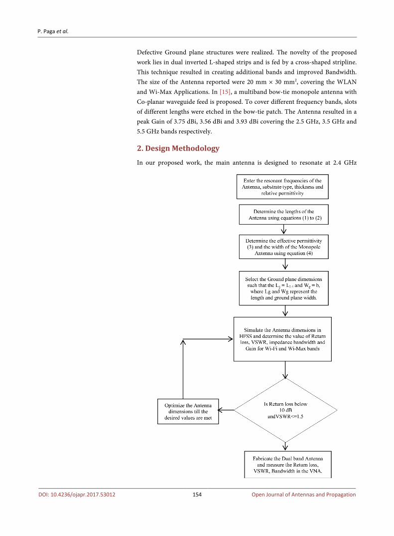
2. Design Methodology
In our proposed work, the main antenna is designed to resonate at 2.4 GHz

P. Paga et al.
DOI: 10.4236/ojapr.2017.53012 155 Open Journal of Antennas and Propagation
which is shown by the longer monopole of length L2.4 and side arm is inserted towards the right of the longer monopole antenna so as to create an additional resonant frequency of 3.5 GHz. The substrate chosen here is a FR4 type which has a dielectric loss tangent of 0.02 and permittivity of 4.4. The substrate thick-ness is kept equal to 1.6 mm. The length and width of the ground planes are se-lected such that the antenna size becomes compact, with the length of the ground plane kept equal to L2.4 and width of the ground plane is selected such that it is approximately equal to the length of the side arm of the monopole.
3. Antenna Design
In the proposed design, the Ground plane has been partially removed to give it a Monopole like structure.
4. Design Equations
Figure 1 shows the snap shot of the antenna designed in HFSS clearly indicating the substrate, the Antenna and the Ground plane. Figure 2 shows the fabricated
Keynote 1: L2.4 represents the length of the monopole resonating at 2.4 GHz and b represents the sec-tion contributing for resonance at 3.5 GHz.
Figure 1. Snapshot of the proposed Dual frequency Monopole Antenna in HFSS.
(a) (b)
Keynote 2: Antenna dimensions are 50 mm by 25 mm on FR4 substrate of thickness 1.6 mm.
Figure 2. (a) Fabricated Dual band Antenna (b) Ground plane view.
P. Paga et al.
DOI: 10.4236/ojapr.2017.53012 156 Open Journal of Antennas and Propagation
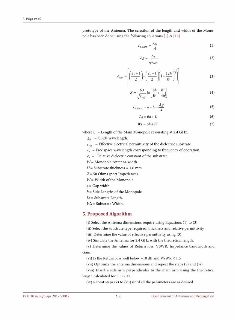
prototype of the Antenna. The selection of the length and width of the Mono-pole has been done using the following equations [1] & [16]
2.4 4GHzgL λ
= (1)
0
reff
gλ
λε
= (2)
121 1 121
2 2r r
reffh
Wε ε
ε
− + − = + +
(3)
60 8ln4reff
h WZW hε = +
(4)
3.5GHz 4gL a b λ
= + = (5)
6Ls h L= + (6)
6Ws h W= + (7)
where L1 = Length of the Main Monopole resonating at 2.4 GHz. gλ = Guide wavelength.
reffε = Effective electrical permittivity of the dielectric substrate.
0λ = Free space wavelength corresponding to frequency of operation.
rε = Relative dielectric constant of the substrate. W = Monopole Antenna width. H = Substrate thickness = 1.6 mm. Z = 50 Ohms (port Impedance). W = Width of the Monopole. a = Gap width. b = Side Lengths of the Monopole. Ls = Substrate Length. Ws = Substrate Width.
5. Proposed Algorithm
(i) Select the Antenna dimensions require using Equations (1) to (3) (ii) Select the substrate type required, thickness and relative permittivity (iii) Determine the value of effective permittivity using (3) (iv) Simulate the Antenna for 2.4 GHz with the theoretical length. (v) Determine the values of Return loss, VSWR, Impedance bandwidth and
Gain. (vi) Is the Return loss well below −10 dB and VSWR < 1.5. (vii) Optimize the antenna dimensions and repeat the steps (v) and (vi). (viii) Insert a side arm perpendicular to the main arm using the theoretical
length calculated for 3.5 GHz. (ix) Repeat steps (v) to (vii) until all the parameters are as desired.

P. Paga et al.
DOI: 10.4236/ojapr.2017.53012 157 Open Journal of Antennas and Propagation
(x) Antenna is fabricated on a FR4 substrate. Simulated and measured results are compared.
6. Simulation & Measured Results
The Antenna has been simulated under HFSS version 15.0 and also fabricated and tested with VNA. The results are indicated as shown.
7. Results and Discussions
The Dual band Antenna resonating at Wi-Fi and Wi-Maxband which is reported here is fabricated and experimentally tested with dimensions as reported in Ta-ble 1. The substrate lengths and widths were set equal to 50 mm by 25 mm. The Length and width of the ground plane was theoretically set equal to quarter of the Guide wavelength corresponding to 2.4 GHz and 3.5 GHz respectively. The Length of the longer monopole arm was set equal to a quarter of the Guide wa-velength corresponding to 2.4 GHz frequency and the side arm length which is perpendicular to main arm is set equal to quarter of the Guide wavelength cor-responding to 3.5 GHz frequency. After theoretical calculations it was found to be 17.1 mm. The length of the side arm (a + b) was calculated at Quarter wave-length resonance condition to arrive at 11.7 mm. Further optimization was done on the longer arm and the side arm resulting in a length of 22.6 mm and 14.3 mm respectively. The width of the feed was calculated using Equation (4) taking the port impedance as 50 Ohms substrate height as 1.6 mm and effective permit-tivity as 4, to arrive at the feed width of 3.0 mm. Figure 3 and Figure 4 show the simulated and measured return loss of the proposed Antennas. The Return loss of the fabricated Dual band Antenna was measured using VNA MASTER MS2308C. Two resonant modes were excited 2.4 GHz and 3.5 GHz. The meas-ured values were 2.7 GHz and 3.426 GHz with an impedance Bandwidth of 0.26 GHz and 2.16 GHz. The bandwidth reported in the upper band was the highest. The measured value of VSWR reported in the Wi-Fi band was 1.53 and that in the Wi-Max band was 1.09 indicating a good impedance match at the upper. The measured values as seen from Figure 4 were 2.7GHz and 3.426 GHz with an impedance Bandwidth of 0.26 GHz and 2.16 GHz as reported in Figure 9. The VSWR reported in Figure 5 is close to 1 indicating a good impedance match. The bandwidth reported in the upper band was the highest. From the Figure 6, the measured value of VSWR reported in the Wi-Fi band was 1.53 and that in the Wi-Max band was 1.09 indicating a good impedance match at the upper band compared to the lower band. Comparing Figure 7 and Figure 8, the simu-lated Bandwidth reported is 330 MHz and 412 MHz for Wi-Fi and the Wi-Max Frequency bands respectively. From Figure 10, peak value Gain is 6.23 dB for 2.4 GHz, and 7.17 dBi in the 3.5 GHz band. The measured radiation pattern as reported in Figure 13 and Figure 14, show that the pattern is omnidirectional for both the 2.4 GHz and the 3.5 GHz frequency bands respectively. Referring to Table 2, we see that the return loss value is more negative in the 2.4 GHz band

P. Paga et al.
DOI: 10.4236/ojapr.2017.53012 158 Open Journal of Antennas and Propagation
Table 1. Geometrical specifications of the Antenna.
Antenna specifications Theoretical Value Optimized Value Substrate Length (Ls) 50 mm 50 mm Substrate Width (Ws) 25 mm 25 mm
Ground plane Length (Lg) 26.7 mm 21 mm Ground plane width (Wg) 12.6 mm 12.0 mm
Feed width (w) 3.0 mm 3.0 mm Length of longer arm (L2.4) 17.1 mm 22.6 mm
Length of the side arm (a + b) 11.7 mm 14.3 mm
Keynote 3: markers m1 and m2 indicate a return loss of −31.79 dB & −24.72 dB for 2.4 GHz and 3.5 GHz.
Figure 3. Return Loss plot of the Monopole Antenna resonating at 2.4 and 3.5 GHz.
Keynote 4: The Horizontal Axis represents the Frequency in GHz and the vertical Axis represents the Return Loss in dB markers MK2 and MK3 represent 2.7 GHz and 3.5 GHz.
Figure 4. Measured Return Loss plot of the Fabricated Monopole Antenna. The Return loss value is −13.38 dB at 2.72 GHz as indicated by marker MK2 and −27.53 dB at 3.5 GHz corresponding to marker MK3.

P. Paga et al.
DOI: 10.4236/ojapr.2017.53012 159 Open Journal of Antennas and Propagation
Keynote 5: Markers m1 and m2 indicate a VSWR value of 1.05 and 1.12 for 2.4 GHz and 3.5 GHz.
Figure 5. Simulated VSWR plot of the Monopole Antenna resonating at 2.4 GHz and 3.5 GHz. The corresponding values of VSWR are 1.05 and 1.12 as indicated by markers m1 and m2.
Keynote 6: The Horizontal axis represents the Frequency in GHz and the vertical Axis represents the VSWR. The markers MK2 and MK3 represent the VSWR corresponding to 1.53 and 1.09 for 2.7 GHz and 3.5 GHz.
Figure 6. Measured VSWR plot of the Monopole Antenna resonating at 2.4 GHz and 3.5 GHz as shown by markers MK2 and MK3. The corresponding values are 1.53 and 1.09 for lower and upper band respectively.

P. Paga et al.
DOI: 10.4236/ojapr.2017.53012 160 Open Journal of Antennas and Propagation
Figure 7. Simulated Bandwidth of the Monopole Antenna resonating at 2.4 GHz indicating a Bandwidth of 330.2 MHz.
Keynote 8: Horizontal Axis represents the Frequency in GHz and the Vertical axis represents the return loss in dB.
Figure 8. Simulated Bandwidth of the Monopole Antenna resonating at 3.5 GHz indicating a Bandwidth of 412.7 MHz. From the figure, the lower −10 dB frequency is 3.33 GHz and the upper −10dB frequency is 3.747 GHz and the difference gives the Bandwidth.
Keynote 9: Horizontal Axis represents the Frequency in GHz and the Vertical Axis represents the Return loss in dB.
Figure 9. Measured Bandwidth of the Dual band Antenna resonating at 2.4 GHz 3.5 GHz as shown by markers MK3, MK4, MK5 and MK6 indicating a Bandwidth of 262 MHz and 2.158 GHz for Wi-Fi and Wi-Max. The markers MK7, MK8 and MK9 indicate the resonant frequencies of 1.5 GHz, 2.7 GHz and 3.429 GHz.
1.00 1.50 2.00 2.50 3.00 3.50 4.00Freq [GHz]
-45.00
-35.00
-25.00
-15.00
-5.00
0.00
dB
(S(1
,1))
3.34353.7424
m1
-10.3203 -9.7881
0.3988
Curve InfodB(S(1,1))
Setup1 : Sw eep

P. Paga et al.
DOI: 10.4236/ojapr.2017.53012 161 Open Journal of Antennas and Propagation
Figure 10. (a) Simulated Gain plot for 2.4 GHz. The peak; (b) Simulated Gain plot for 3.5 GHz in-dicating a Gain reported is 6.236 dB. peak Gain of 7.17 dBi.
Keynote 11: The vertical Axis represents a peak gain of 6.23 dBi for the E and H plane. The pattern is Hemis-pherical in H plane and figure of 8 in E plane.
Figure 11. Simulated radiation pattern of Antenna at 2.4 GHz (a) under H plane and (b) under E plane.

P. Paga et al.
DOI: 10.4236/ojapr.2017.53012 162 Open Journal of Antennas and Propagation
compared to 3.5 GHz band indicating a good impedance match close to 50 Ohms in the lower band compared to the higher band. Both the Gain and the Bandwidths are increased by a factor of 0.9 dB and 88.5 MHz in the upper com-pared to lower band respectively. Comparing Figure 11, we see that the peak boresignt gain is 6.23 dBi under both E and the H plane at 2.4 GHz. But the pat-tern in H plane is Figure 8. Comparing Figure 12, we see that the peak boresight Gain is 6.5 dB and 7.17 dB under H and E planes. Referring to Table 3, we see that the measured Bandwidth reported is very high close to 2.16 GHz in the up-per band compared to lower band and also there is a shift in the resonant Fre-quency from 2.4 GHz to 2.7 GHz in the lower band. Referring to Table 4 and Table 5, we see that both the Gain and Bandwidths reported in the present work are high compared to other designs reported in [6] [7] and [10] at 2.4 GHz and 3.5 GHz Frequency. Figure 15 indicates that there is a good improvement in the
(a) (b)
Keynote 12: the radiation pattern indicates a peak bore sight gain of 6.5 dB under H plane and 7.17 dB under E plane for 3.5 GHz.
Figure 12. Simulated radiation pattern of Antenna at 3.5 GHz (a) H plane (b) E plane. From the pattern it is clear that there are some side lobes are appearing at −180 degrees.
Keynote 13: The measured radiation pattern is nearly omni directional in E plane for both the frequencies.
Figure 13. Measured Normalized E-plane radiation pattern of Antenna at (a) 2.4 GHz and (b) 3.5 GHz.
-18.00
-11.00
-4.00
3.00
90
60
30
0
-30
-60
-90
-120
-150
-180
150
120
m1
-10.00
-5.00
0.00
5.00
90
60
30
0
-30
-60
-90
-120
-150
-180
150
120
m1

P. Paga et al.
DOI: 10.4236/ojapr.2017.53012 163 Open Journal of Antennas and Propagation
Keynote 14: The radiation pattern is nearly omni-directional for both the frequencies. The pattern is normalized to 0 dB.
Figure 14. Measured normalized H-plane radiation pattern of Antenna at (a) 2.4 GHz and (b) 3.5 GHz.
Table 2. Showing the comparison of the Simulated Antenna parameters at 2.4 GHz and 3.5 GHz.
2.4 GHz 3.5 GHz
Return Loss −31.79 dB −24.72 dB
VSWR 1.058 1.123
Port Impedance 52.3825 Ohms 44.6874 Ohms
Bandwidth 330.2 MHz 412.7 MHz
Gain 6.2364 dBi 7.1758 dBi
Table 3. Showing the comparison of the Simulated and Fabricated Antenna Results.
Simulated Results Measured Results
Resonant Frequency 2.4 GHz and 3.5 GHz 2.72 GHz and 3.426 GHz
VSWR 1.058 (2.4 GHz)
& 1.123 (3.5 GHz) 1.53 (2.72 GHz)
& 1.09 (3.426 GHz)
Return Loss −31.79 dB (2.4 GHz)
& −24.72 dB (3.5 GHz) −13.38 dB (2.72 GHz
& −27.53 dB (3.5 GHz)
Bandwidth 330.2 MHz(2.4 GHz)
& 412.7 MHz (3.5 GHz) 0.26 GHz (2.4 GHz)
& 2.16 GHz (3.5 GHz)
Table 4. Showing the comparison of the Simulated results reported in the paper with [6] [7] and [10] at 2.4 GHz.
Antenna parameters Present work [6] [7] [10]
Return Loss −31.79 dB −18.0 dB −32 dBi −25 dB
Bandwidth 330.2 MHz 110.0 MHz 180 MHz 110 MHz
Gain 6.326 dBi 1.55 dBi 2.78 dBi 2.1 dBi

P. Paga et al.
DOI: 10.4236/ojapr.2017.53012 164 Open Journal of Antennas and Propagation
Table 5. Showing the comparison of the Simulated results reported in the paper with [6] [7] and [10] at 3.5 GHz frequency.
Antenna parameters Present work [6] [7] [10]
Return Loss −24.72 dB −17.5 dB −29 dB −17.5 dB
Bandwidth 412.7 MHz 700.0 MHz 380 MHz 260 MHz
Gain 7.1758 dBi 1.6 dBi 2.14 dBi 3.4 dBi
Keynote 15: X Axis represents the Reference papers and Y Axis represents the Return Loss in dB.
Figure 15. Showing the comparison of the Simulated results reported in the paper with [6] [7] and [10] at 3.5 GHz frequency.
Keynote 16: X Axis represents the Reference papers and Y Axis represents the Gain in dBi.
Figure 16. Showing the comparison of the Gain reported in the present work with similar other works reported in [6] [7] and [10]. X Axis represents the Dual Frequency bands obtained in References [6] [7] & [10] and Y Axis represents the Gain in dBi.
Return loss, namely 13.79 dB and 6.79 dB compared to [6] and [10] for the Wi-Fi Frequency band of interest. But in the Wi-Max band, there is a 7.22 dB improvement in the return loss compared to [6] and [10]. From Figure 16, it is clear that there is a 3.546 dB and 4.226 dB improvement in the Gain compared to [7] and [10] in the lower frequency bands of interest. While in the upper band there is a 5.03 dB and 3.7758 dB improvement in the Gain compared to [7] and [10]. As far as the Bandwidth of the Antenna is concerned Figure 17 shows that

P. Paga et al.
DOI: 10.4236/ojapr.2017.53012 165 Open Journal of Antennas and Propagation
Keynote 17: Y Axis represents the Bandwidth in MHz and X Axis represents the Reference papers.
Figure 17. Showing the comparison of the Bandwidth reported in the present work with similar other works reported in [6] [7] and [10]. X Axis represents the Dual Frequency bands obtained in References [6] [7] & [10] and Y Axis represents the Bandwidth in MHz.
there is a 200.2 MHz improvement in the Bandwidth reported in the present work compared to [6] & [10] at 2.4 GHz frequency band. But at 3.5 GHz fre-quency band, there is a 32.7 MHz and 152.7 MHz improvement in the Band-width at the upper frequency band of interest compared to [7] and [10].
8. Conclusion
A novel Antenna for Wi-Fi and Wi-Max band of frequencies has been proposed. It is etched on a FR4 substrate with a permittivity of 4.4. By employing two per-pendicular strips, the Antenna has been made to resonate at the Dual band. The measured S11 were −13.38 dB and −27.53 dB for the 2.4 GHz band and the 3.5 GHz band respectively. The measured bandwidth of the proposed Antenna was 0.26 GHz and 2.16 GHz in the lower and upper band respectively. The size of the Antenna reported is 50 mm by 25 mm, thus making it compact in size.
Acknowledgements
The authors would like to thank M/s Aniritsu Technologies Limited Bangalore for helping us in characterization of the Antenna parameters for Reflection coef-ficient, VSWR and Bandwidth measurements using the Vector Network Ana-lyzer model No. VNA MASTER MS2308C. The Authors would also like to thank Dr. K.J. Vinoy, Professor, IISc for allowing us to take the pattern measurement in Anachoic chamber.
References [1] Prasanna Paga, Nagaraj, H.C., Rukmini, T.S. and Nithin, N.E. (2015) Design and
Fabrication of Microstrip printed T monopole antenna for ISM applications. Inter-national Conference on Microwave, Optical and Communication Engineering, 18-20 December 2015, IIT, Bhubaneswar. https://doi.org/10.1109/ICMOCE.2015.7489742

P. Paga et al.
DOI: 10.4236/ojapr.2017.53012 166 Open Journal of Antennas and Propagation
[2] Jithu, P., Paul, A., Pithadia, V., Misquitta, R. and Khot, U.P. (2013) Dual Band Mo-nopole Antenna Design. International Journal of Engineering and Technology (IJET), 5, 2297-2302. http://www.enggjournals.com/ijet/docs/IJET13-05-03-036.pdf
[3] Shah, I.A., Hayat, S., Khan, I., Alam, I., Ullah, S. and Afridi, A. (2016) A Compact, Tri-Band and 9-Shape Reconfigurable Antenna for WiFi, WiMAX and WLAN Ap-plications. International Journal of Wireless and Microwave Technologies, 5, 45-53. https://doi.org/10.5815/ijwmt.2016.05.05
[4] Huang, S.S., Li, J. and Zhao, J.Z. (2014) Design of a Compact Triple-Band Mono-pole Planar Antenna for WLAN/WiMAX Applications. Progress in Electromagnet-ics Research C, 48, 29-35. https://doi.org/10.2528/PIERC13122202
[5] Li, L., Rao, S.-H., Tang, B. and Li, M.-F. (2013) A Novel Compact Dual-band Mo-nopole Antenna Using Defected Ground Structure. International Workshop on Microwave and Millimeter Wave Circuits and System Technology, 24-25 October 2013, Chengdu. https://doi.org/10.1109/MMWCST.2013.6814645
[6] Wang, H.J. and Li, H. A Compact Triple-Band Monopole Antenna for WLAN/WiMAX.
[7] Wang, T., Yin, Y.Z., Yang, J., Zhang, Y.L. and Xie, J.J. (2012) Compact Triple-Band Antenna Using Defected Ground Structure for WLAN/WIMAX Applications. Progress in Electromagnetics Research Letters, 35, 155-164. https://doi.org/10.2528/PIERL12082814
[8] Zahraoui, I., Errkik, A., Zbitou, J., Abdelmounim, E. and Mediavilla, A.S. (2016) A New Design of a Microstrip Antenna with Modified Ground for DCS and WiMAX Applications. International Journal of Microwave and Optical Technology, 11, No. 4.
[9] Zakaria, Z., Zainuddin, N.A., Abd Aziz, M.Z.A., Husain, M.N. and Mutalib, M.A. (2013) Dual-Band Monopole Antenna for Energy Harvesting System. IEEE Sympo-sium on Wireless Technology and Applications (ISWTA), Kuching, Malaysia, 22-25 September 2013. https://doi.org/10.1109/iswta.2013.6688775
[10] Zhang, S.M., Zhang, F.S., Li, W.M., Li, W.Z. and Wu, H.Y. (2012) A Multi-Band Monopole Antenna with Two Different Slots for WLAN and WIMAX Applications. Progress in Electromagnetics Research Letters, 28, 173-181. https://doi.org/10.2528/PIERL11111505
[11] Huang, H., Liu, Y., Zhang, S. and Gong, S. (2015) Multiband Metamaterial-Loaded Monopole Antenna for WLAN/WiMAX Applications. IEEE Antennas and Wireless Propagation Letters, 14, 662-665. http://or.nsfc.gov.cn/bitstream/00001903-5/320065/1/1000013482596.pdf https://doi.org/10.1109/LAWP.2014.2376969
[12] Sun, X.L., Cheung, S.W. and Yuk, T.I. (2013) Compact Dual-Band Monopole An-tenna for 2.4/3.5 GHz WiMAX Applications. Progress in Electromagnetics Research Symposium Proceedings, Taipei, 25-28 March 2013. https://doi.org/10.1002/mop.27710
[13] Tan, M.-T. and Wang, B.-Z. (2016) A Dual-Band Circularly Polarized Planar Mo-nopole Antenna for WLAN/Wi-Fi Applications. IEEE Antennas and Wireless Propagation Letters, 15, 670-673. http://ieeexplore.ieee.org/stamp/stamp.jsp?arnumber=7185377 https://doi.org/10.1109/LAWP.2015.2466596
[14] Liu, W.-C., Wu, C.-M. and Dai, Y. (2011) Design of Triple-Frequency Micro-strip-Fed Monopole Antenna using Defected Ground Structure. IEEE Transactions on Antennas and Propagation, 59, 2457-2463.

P. Paga et al.
DOI: 10.4236/ojapr.2017.53012 167 Open Journal of Antennas and Propagation
https://doi.org/10.1109/TAP.2011.2152315
[15] Wu, M.-T. and Chuang, M.-L. (2015) Multibroadband Slotted Bow-Tie Monopole Antenna. IEEE Antennas and Wireless Propagation Letters, 14, 887-890. http://ieeexplore.ieee.org/stamp/stamp.jsp?arnumber=6990588 https://doi.org/10.1109/LAWP.2014.2383441
[16] Balanis, C.A. (2008) Modern Antenna Handbook. Wiley, New York. https://doi.org/10.1002/9780470294154
Submit or recommend next manuscript to SCIRP and we will provide best service for you:
Accepting pre-submission inquiries through Email, Facebook, LinkedIn, Twitter, etc. A wide selection of journals (inclusive of 9 subjects, more than 200 journals) Providing 24-hour high-quality service User-friendly online submission system Fair and swift peer-review system Efficient typesetting and proofreading procedure Display of the result of downloads and visits, as well as the number of cited articles Maximum dissemination of your research work
Submit your manuscript at: http://papersubmission.scirp.org/ Or contact [email protected]


![TW AUDiO Presets KDSP Preset guide EN 1 · 10 dB -S dB -10 dB -20 dB — -25 dB -30 dB -40 dB O dB MUTE Options Magnitude [-12 12] Layer I 16Hz Layer 2 Layer 3 Delay ms 1.715 m -12d8](https://img.pdfslide.us/doc/110x75/60d3e9cc1ee64b29d6441834/tw-audio-presets-kdsp-preset-guide-en-1-10-db-s-db-10-db-20-db-a-25-db-30.jpg)