Embed Size (px)
Citation preview

Soil Dynamics week # 8
1/11
Design Procedures For Dynamically Loaded Foundations Choice of parameters for equivalent lumped systems
Lumped mass : the mass of the foundation and supported machinery Damping : ① Geometrical(or radiation) damping – by the decrease in energy
density through propagation of elastic waves away from the vicinity of the footing. (Table A-2) (Fig. 7-19)
② internal damping – by energy loss within the soil due to hysteretic
and viscous effects. (Table 10-12)
SNU Geotechnical and Geoenvironmental Engineering Lab.

Soil Dynamics week # 8
2/11
Typical value of the internal damping ratio – 0.05 (Table 10-12) → for vertical & sliding mode, negligible (Fig 7-19) (∵geometric damping >>0.05) → for torsional & rocking mode, should be included (Fig-7-19)
Influence of partial embedment – reduction in amplitude on the order of 10~25% depending on the mode of vibration
→ neglection of embedment effect errs on the conservative side
Influence of the underlying rigid layer increase the amplitude of vibration at resonance
SNU Geotechnical and Geoenvironmental Engineering Lab.

Soil Dynamics week # 8
3/11
Spring constant : the most critical factor
Governs ① The static displacement ② magnification factor, M ③ the resonant frequency
Obtained by ① Tests on prototype foundation ② Tests on model footings (the extrapolation procedure governs the value) ③ formulas (Tables 10-13, 10-14) (applies to rigid block or mat foundations w/ shallow embedment)
SNU Geotechnical and Geoenvironmental Engineering Lab.

Soil Dynamics week # 8
4/11
Elastic constants : G & v
v – cohesionless soils (0.25~0.35) → 13
cohesive soils (0.35~0.45) → 0.40
G – ① From static plate-bearing tests → get → backcalculate G using formula k ② resonant – column test in the lab ③ from the void ratio of the soil & the probable confining pressure
For round-grained sands (e < 0.80)
2
0.5 20
2630(2.17 ) ( ) [ / ]1
eG le
σ−=
+b in
For angular-grained material (e > 0.6)
2
0.5 20
1230(2.97 ) ( ) [ /1
eG le
σ−=
+]b in
(also good for NC clay w/ low surface activity) ④ From the shear wave velocity 2
sG vρ=
SNU Geotechnical and Geoenvironmental Engineering Lab.

Soil Dynamics week # 8
5/11
Brief review of other methods or results
DEGEBO(Deutschen Forschungsgesellschaft fu⋅⋅
r Bodenmechanik) :
Using a rotating-mass mechanical oscillator (fig 10-11), run extensive number of tests.
In 1933, reported the followings, - dynamic response → non-linear - progressive settlement developed - dynamic response depends on
① the total weight of the oscillator and base plate ② the area of the base plate
③ dynamic force applied
④ the characteristics of the soil
- established a table for the ‘characteristic frequency’ for a variety of soils
→ ‘natural frequency’ of soil (incorrect concept)
In 1934, reported on the effect of oscillator weight, base-plate area, and
exciting force - increasing the total weight → lowered the resonant frequency
- increase in the base-plate area → raised the resonant frequency.
- increase in exciting force → lowered resonant frequency.
(this indicates that the soil response is non-linear)
SNU Geotechnical and Geoenvironmental Engineering Lab.
Soil Dynamics week # 8
6/11
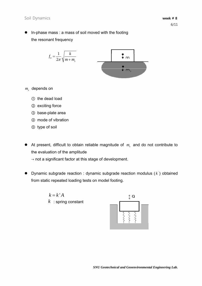
In-phase mass : a mass of soil moved with the footing the resonant frequency
12n
s
kfm mπ
=+
sm depends on
① the dead load ② exciting force ③ base-plate area ④ mode of vibration ⑤ type of soil
At present, difficult to obtain reliable magnitude of sm and do not contribute to
the evaluation of the amplitude → not a significant factor at this stage of development.
Dynamic subgrade reaction : dynamic subgrade reaction modulus ( 'k ) obtained
from static repeated loading tests on model footing.
'k k A= k : spring constant
SNU Geotechnical and Geoenvironmental Engineering Lab.

Soil Dynamics week # 8
7/11
- extrapolating formula(Terzaghi, 1955)
cohesive : 11' '
2z zk kd
=
cohesionless : 21
2 1' ' (4z zdk k
d)+
=
2d=width(or least dimension) of beam, =least dimension = 1ft 1'zk
- or Table 10-10
Other modes ( 'zk = vertical mode)
Horizontal ' 0.5 'x zk k≈
Rocking ' 2 zk kψ '≈
Torsional ' 1.5 'zk kθ ≈
- Gives no useful information on the amplitude of motion at frequencies near
resonance
SNU Geotechnical and Geoenvironmental Engineering Lab.

Soil Dynamics week # 8
8/11
Isolation of foundations Mechanical isolation
Isolation by location Isolation by barriers
Mechanical isolation
use isolation absorbers : rubber, springs, spring-damper system, pneumatic spring
Isolation by location :
- geometrical damping
11
rw wr
=
(where, w : amplitude of motion, r : distance)
(note that 1 1w r w r= = constant, ie. no energy loss)
- material damping [∵soil is not perfectly elastic]
11 1exp[ ( )], ( )rw w r r r r
rα= − − 1>
α : the coefficient of attenuation. (0.01~0.04 (1/ft)) (energy loss due to material damping)
SNU Geotechnical and Geoenvironmental Engineering Lab.

Soil Dynamics week # 8
9/11
Isolation by barriers [at least reduction of amplitude to 0.25]
Active isolation : isolation at the source Passive isolation : screening at a distance Examples from practice
active isolation (covers the area extending to 10 RL )
- with trenches fully surrounding the source / 0RH L ≥ .6
(H : trench depth, : Rayleigh wave length(RL RR
vLf
= ) )
[note that , not much improvement, i.e. > 0.10] / 2RH L = .0
.6
R
- with partially surrounding trenches / 0RH L ≥
passive isolation - (for ) / 1.33RH L ≥ 2 7R RL R L≤ ≤
- vertical trench area( ) should / /RH L L L×
be increased as the R increases ex. For the same degree of isolation
trench area 2.5 at R=2 → 6 at R=7 RL RL
SNU Geotechnical and Geoenvironmental Engineering Lab.

Soil Dynamics week # 8
10/11
SNU Geotechnical and Geoenvironmental Engineering Lab.

Soil Dynamics week # 8
11/11
SNU Geotechnical and Geoenvironmental Engineering Lab.
Figure 8-4. Isolation of standards laboratory(after McNeill et al., 1965)
Figure 8-7. Schematic of vibration isolation using a straight trench to create a
quiescent zone – passive isolation(from Woods, 1968)