Embed Size (px)
Citation preview
Design Pattern Oriented Development
of Model Transformations
Huseyin Ergina, Eugene Syrianib, Jeff Graya
aUniversity of Alabama, Tuscaloosa, Alabama, U.S.A.bUniversity of Montreal, Montreal, Canada
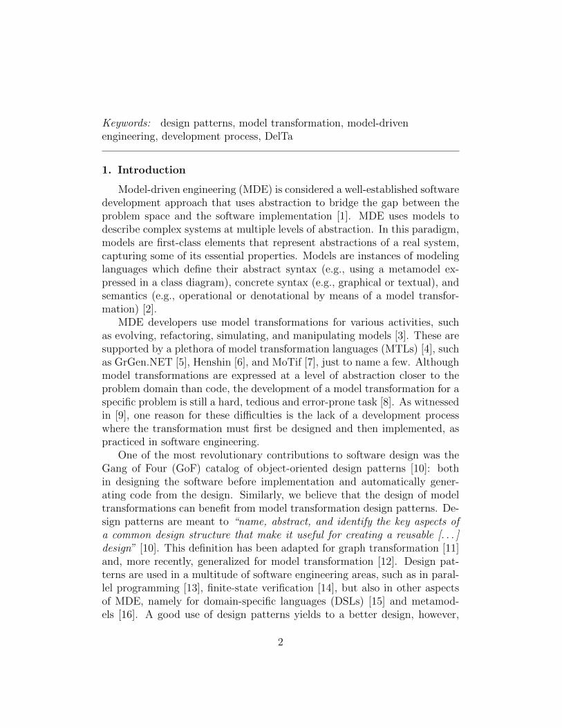
Abstract
Model-driven engineering (MDE) is considered a well-established softwaredevelopment approach that uses abstraction to bridge the gap between theproblem space and the software implementation. In MDE, many problemsare solved using model transformation, which is a paradigm that manipulateshigh-level models to translate, evolve, or simulate them. However, the devel-opment of a model transformation for a specific problem is still a hard task.The main reason is the lack of a development process where transformationsmust be designed before implemented. Design patterns provide experien-tial reuse to software engineers when faced with recurring problems. Giventheir various contexts of application, model transformations may also benefitfrom design patterns. Although several studies have proposed design pat-terns for model transformation, there is still no accepted common languageto express transformation patterns. Therefore, we propose a semi-formal wayto describe model transformation design patterns that is independent froma specific transformation language and described in a practical way that isdirectly implementable by model engineers. This paper presents a catalogof 15 model transformation design patterns. We also demonstrate how itis possible to automatically generate excerpts of a model transformation invarious languages given a design pattern. We conducted an initial surveyto motivate the need for model transformation design patterns and a userstudy to validate the methodology we propose to solve problems as modeltransformations based on design patterns.
Email addresses: [email protected] (Huseyin Ergin),[email protected] (Eugene Syriani), [email protected] (Jeff Gray)
Preprint submitted to Computer Languages, Systems and Structures June 8, 2016
Keywords: design patterns, model transformation, model-drivenengineering, development process, DelTa
1. Introduction
Model-driven engineering (MDE) is considered a well-established softwaredevelopment approach that uses abstraction to bridge the gap between theproblem space and the software implementation [1]. MDE uses models todescribe complex systems at multiple levels of abstraction. In this paradigm,models are first-class elements that represent abstractions of a real system,capturing some of its essential properties. Models are instances of modelinglanguages which define their abstract syntax (e.g., using a metamodel ex-pressed in a class diagram), concrete syntax (e.g., graphical or textual), andsemantics (e.g., operational or denotational by means of a model transfor-mation) [2].
MDE developers use model transformations for various activities, suchas evolving, refactoring, simulating, and manipulating models [3]. These aresupported by a plethora of model transformation languages (MTLs) [4], suchas GrGen.NET [5], Henshin [6], and MoTif [7], just to name a few. Althoughmodel transformations are expressed at a level of abstraction closer to theproblem domain than code, the development of a model transformation for aspecific problem is still a hard, tedious and error-prone task [8]. As witnessedin [9], one reason for these difficulties is the lack of a development processwhere the transformation must first be designed and then implemented, aspracticed in software engineering.
One of the most revolutionary contributions to software design was theGang of Four (GoF) catalog of object-oriented design patterns [10]: bothin designing the software before implementation and automatically gener-ating code from the design. Similarly, we believe that the design of modeltransformations can benefit from model transformation design patterns. De-sign patterns are meant to “name, abstract, and identify the key aspects ofa common design structure that make it useful for creating a reusable [. . . ]design” [10]. This definition has been adapted for graph transformation [11]and, more recently, generalized for model transformation [12]. Design pat-terns are used in a multitude of software engineering areas, such as in paral-lel programming [13], finite-state verification [14], but also in other aspectsof MDE, namely for domain-specific languages (DSLs) [15] and metamod-els [16]. A good use of design patterns yields to a better design, however,
2

anti-patterns, which represent bad patterns to apply, also play an importantrole to prevent common mistakes [17]. Design patterns are also used to com-municate about the design, which facilitates design planning, discussion, anddocumentation [18], given they provide a common vocabulary for design [19].
Several design patterns studies have been proposed for model transfor-mation [11, 12, 20, 21]. However, the literature shows no consensus on howto represent these design patterns, especially not in a form independent fromexisting MTLs, which hampers their reuse and adoption. This also limitsthe potential to automatically generate concrete model transformation so-lutions from design patterns, because each design pattern is represented indifferent languages instead of a unified language. GoF design patterns aredescribed using various UML diagrams in order to make the design patternstructure more readable and understandable, which also greatly helps theautomatic generation of the software code [22]. As stated in [23], a designpattern language must be independent from any MTL in which patternsare implemented. Furthermore, a pattern language must be fit to definepatterns rather than transformations. A design pattern language must alsobe understandable and implementable by a transformation model engineer1.Additionally, a pattern language must allow one to verify if a transformationcorrectly implements a pattern. Design pattern catalogs evolve over timeand new patterns keep on being discovered due to the evolving nature ofsoftware and reuse habits of model engineers [24, 25, 26]. Therefore, the de-sign pattern language must not only support the expression of known designpatterns, but also be open to define new ones. A first attempt to create amodel transformation design pattern language can be found in [27]. Morerecently, Lano et al. [12] published a broader study about the topic.
In this paper, we explore existing studies in model transformation designpatterns and identify 14 unique “real” design patterns in the literature. Thefirst contribution is a new unified formalism to describe model transformationdesign patterns that consists of a template to describe and discuss a patternalong with a modeling language to represent the structure of its solution.The second contribution is the conduction of a survey across the communityof model transformation engineers to identify the needs for design patternsand a dedicated unified language to express them. This paper can be consid-
1Through the paper, we use “model engineer” in place of “user” or “developer” of amodel transformation.
3

ered a response to the demands of the model transformation community inmatters of design patterns. The third contribution is a process, aided witha tool we implemented, to guide model transformation engineers in theirdesign by automatically instantiating patterns in the MTL of their choice,using template-based code generation. Finally, we define an additional designpattern as the 15th, “execution by translation.”
The rest of the paper is organized as follows. In Section 2, we presentthe results of the pilot survey, where we motivate the need for a languageto express model transformation design patterns. In Section 3, we explainthe terminology to distinguish between different reuse structures and discussexisting work, the different notations used to express model transformationdesign patterns, along with the classification of the patterns in the literature.In Section 4, we present the unified template to describe model transforma-tion design patterns and, in particular, the modeling language DelTa to definethe structure of the patterns. In Section 5, we demonstrate how all existingmodel transformation design patterns, as well as new ones, use the unifiedtemplate. In Section 6, we propose a development process of model trans-formations driven by design patterns. We also discuss the implementation ofthe model transformation generator. In Section 7, we validate the method-ology along with the tool and the language with a user study. Finally, weconclude in Section 8.
2. Pilot Motivation Survey
In order to determine whether a design pattern language for model trans-formation is useful, we conducted a survey. The research questions identifiedare:
RQ1 Is there a need for a common language to describe model transforma-tion design patterns?
RQ2 Is DelTa an appropriate candidate to describe model transformationdesign patterns?
RQ3 How can a model transformation design pattern improve the imple-mentation of model transformations?
4
2.1. Data Collection
We have prepared an online survey2 with a total of 22 questions. Wehave also supported some of the questions by asking the reason behind theanswer. The survey was closed to selected participants only. We have usedthe Qualtrics3 software to analyze the results.
2.2. Experimental Setup
There was no time limit to complete the survey and participants hadaccess to any resource they needed. The survey consists of four blocks ofquestions or explanations. The first block has 10 questions and focuses onbackground information about the participants, such as familiarity with de-sign patterns, software design, and model transformation. The second blockhas no questions but introduces DelTa and its purpose in a paragraph alongwith referring the participant to another document that shows DelTa con-crete syntax in details. In the third block, we test the ability of participantsto understand and interpret two design patterns in which the structure isrepresented in DelTa: a simple one (entities before relations) and a morecomplex one (fixed point iteration) from [27]. Here, the level of complexityis relative to the number of constructs used in the design pattern. We asked4 questions for each of the design patterns. The final block has 4 questionsand collects their opinion regarding the three research questions.
2.3. Participants
We selected participants from attendees at conferences and workshopswhere model transformation is a main topic of interest (e.g., InternationalConference on Model Transformation, Transformation Tool Contest). Ad-ditionally, the participants must have developed at least one model trans-formation in the past. A total of 23 participants ended up completing thesurvey. According to the background question results, 95% of the partici-pants develop software for academic purposes and an average of 27% of theirdevelopment time focuses on the design phase. 44% of the participants usehand sketches for designing and 26% use a UML tool for software develop-ment. All participants were familiar with object-oriented design patterns.On average, 39% of their development time included model transformations.
2http://tinyurl.com/DelTaSurvey20153www.qualtrics.com/
5
Language Used by
ATL [28] 36%ETL [29] 23%Henshin [6] 9%MoTif [7] 9%QVT-OM [30] 9%
Table 1: The five most used model transformation languages (multiple choice)
Design Activity Performed by
Hand sketching 64%Directly implement without designing first 18%Think of solution in mind 14%Use image editing tools 14%Tool used has support for design 9%
Table 2: Design activities performed while planning and solving a model transformationproblem (multiple choice)
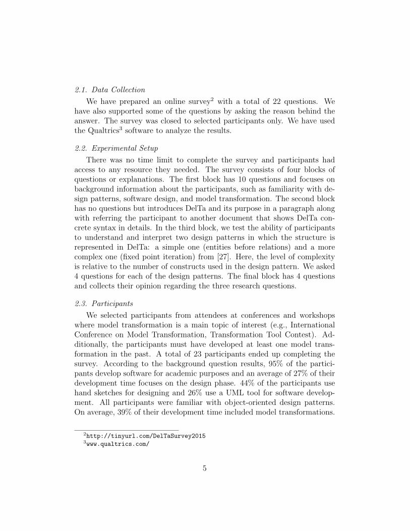
2.4. Results of Transformation Survey
Table 1 shows the most popular model transformation languages amongthe participants. They could choose multiple selections from 11 languageswe proposed and another field where they can enter the name of an MTLnot listed. Table 2 lists the design activities performed by the participantswhile planning and solving a model transformation problem. Activities in-cluded a range of options from hand sketches to the tool’s built-in supportfor design. Some languages (e.g., MoTif, GrGen.NET) have dedicated IDEsthat let the model engineers design immediately. Table 3 depicts the par-ticipants’ understanding of the design pattern and how to implement it intheir language. Finally, 82% of the participants agree that it is appropriateto design the solution using a specific notation first, before implementing thetransformation and 68% agree that it is useful to have a language dedicatedto designing model transformations, analogously to UML for object-orientedprograms. The complete results of this survey are available online4.
4http://tinyurl.com/DelTaSurveyResults
6

Comprehension Design Pattern 1 Design Pattern 2
Understand the design pattern 91% 86%Can see how to implement it 68% 68%
Table 3: Comprehension of the design patterns
2.5. Discussion of Transformation Survey Results
RQ1: 64% of the model engineers resort to hand sketches when planningthe solution to a problem that will use a model transformation. The mainreason reported is due to the lack of tools to design model transformations.A large majority (68%) agree that a language for this purpose, such as DelTa,is needed.
RQ2: Although 12 out of 22 participants stated that DelTa is an appro-priate design pattern language (7 participants were neutral about DelTa),they have almost unanimously understood both patterns well. Furthermore,59% stated that patterns described in DelTa are easily implementable intheir favorite model transformation language. We also directly asked aboutthe understandability and implementability of the design patterns with a 5-scale, from strongly agree to strongly disagree. The results are in Table 3.Nevertheless, we did not have empirical evidence of this when we conductedthe survey, but now Section 6 validates this statement. It is important tonote that the survey used the earlier version of DelTa presented in [31],but in graphical concrete syntax. Following the comments gathered fromthis survey, we incorporated several of the useful improvements suggested bythe participants, e.g., removal of transformation block, converting random tochoice. This led to the version of DelTa presented in Section 4.2. Three par-ticipants stated they did not think DelTa is an appropriate language. Twoof them were suspicious about the benefits of introducing a new language,given the already many existing MTLs. However, DelTa is not an MTL, buta language for describing design patterns which abstracts concepts presentin existing MTLs. The other participant was worried that DelTa could notexpress complex transformations. However, DelTa does not aim at definingcomplete transformations, but at restraining how a transformation should beimplemented.
RQ3: Besides regular improvements of the transformation code (such asreadability, understandability, optimization), a model transformation designpattern helps the model engineers to change their current behavior. There is
7

still a large majority of model engineers doing hand sketches to design a modeltransformation before implementation (64%). The model engineers tend touse a tool if it exists. Also, they think DelTa is an appropriate language toexpress model transformation design patterns. Therefore, a tool with a semi-automatic generation from DelTa design patterns to model transformationsolutions in a MTL should definitely help. In addition, model engineers thinkit may help to document the knowledge in the domain and understand thecomplexity of the transformation before implementation.
2.6. Threats to Validity
There are various threats to the validity of this survey. Threats to in-ternal validity include the need to understand DelTa before answering thesurvey questions about design patterns. Although DelTa’s aim is to simplifyand increase the understandability of the design pattern structure, model en-gineers are suggested to read the paper in which DelTa is introduced [27] anda reference guide to understand graphical syntax of DelTa as depicted in Ap-pendix B. We have tried to eliminate this threat by making the introductionas clear as possible in the latter document.
Threats to external validity include the experience level of the modelengineers. All our model engineers are from an academic background. Oneother threat is the number of participants and how far we can generalizethe results. We have asked questions about their experiences with modeltransformations.
3. Existing Work on Model Transformation Design Patterns
In the following, after we define the terminology, we discuss initial workson design patterns for model transformation and, in particular, a recentlypublished catalog [12]. We also classify the existing design patterns accordingto our terminology.
3.1. Terminology
We note that not all model transformation design patterns proposed inthe literature should be considered as a design pattern; some are reusable id-ioms, even refactoring patterns, and others are specific to a particular modeltransformation language, which some can be generalized as a design pattern.A design pattern should be language-independent and applicable in variousMTLs, whereas a reusable idiom is only applicable within the context of
8
a specific MTL. Additionally, a design pattern is a reusable solution thatshould be applicable whether the transformation on which it will be appliedexists (e.g., to optimize the transformation) or not (e.g., to design the trans-formation from the beginning). This leads to the difference between a designpattern and a refactoring pattern, where the latter is only applicable whenthere is an existing solution. We distinguish between the following concepts:
� Reusable Idioms are language-specific structures that are reusablewithin a single MTL [11]. They are often presented as a feature builtinto the MTL, e.g., multiple matching pattern in ATL [21].
� Design patterns are language-independent solutions to a class ofproblems and are applicable to any MTL [10], e.g., mapping pattern [20].
� Refactoring patterns are language-independent structures that im-prove an existing transformation according to some quality criteria [32],e.g., introduce rule inheritance [12].
3.2. Reusable Idioms
Initial studies on model transformation design patterns proposed usefulidioms that are specific to model transformation languages: GReAT [11],QVT-R [20], ATL [21], and VMTS [33]. Therefore, they should not be con-sidered as design patterns for model transformation, but reusable idiomsin a specific MTL. Additionally, they are all defined as model transforma-tions, rather than patterns, and use specific input and output metamodels.Therefore, it is not clear how to reuse these patterns for different applicationdomains or in other languages.
The first work that proposed design patterns for model transformationwas by Agrawal et al. [11]. They defined the transitive closure patternto calculate transitive closure of the links in a graph structure. The leafcollector pattern traverses a hierarchical tree to find and process all leaves.The proxy generator idiom is not a general design pattern, since it is specificto languages modeling distributed systems where remote interactions to thesystem need to be abstracted and optimized. These patterns are defined inthe GReAT language.
Iacob et al. [20] defined five other design patterns for outplace transfor-mations, where the input model is not modified during the transformationand the output is a separate model. The mapping pattern first maps entitiesand then relations. Because it is described using QVT-R, we consider it as
9
an implementation of the entity-relation mapping pattern described in [27].The refinement pattern proposes to transform an edge into a node with twoedges in the context of a refinement transformation, so that the target modelcontains more detail. The node abstraction pattern abstracts a specific typeof node from the target model while preserving its original relations. Theflattening pattern removes the composition hierarchy of a model by replac-ing the containment relations. The duality pattern is not a general designpattern, because it is specific to data flow modeling languages that convertedges to nodes in the flow.
Bezivin et al. [21] mined ATL transformations and discovered two de-sign patterns. The transformation parameters pattern suggests to modelexplicitly auxiliary variables needed by the transformation in an additionalinput metamodel, instead of hard-coding them in ATL helpers. The multiplematching pattern shows how to match multiple elements in the from partof an ATL rule. Newer versions of ATL already support this feature, whichmakes this pattern obsolete.
Levendovszky et al. [33] proposed domain-specific design patterns formodel transformation as well as different DSLs. In their approach, theydefined design patterns using a specific MTL, VMTS, where rules supportmetamodel-based pattern matching. They proposed two design patterns: thehelper constructs in rewriting rules pattern explicitly produces traceabilitylinks, and the optimized transitive closure pattern which is similar to the onefrom Agrawal et al. [11].
3.3. Design and Refactoring Patterns
Recently, Lano et al. [12] provided the most comprehensive model trans-formation design pattern study. This study proposes a total of 29 patternsclassified in five categories.
Rule modularization patterns are meant to “improve the structural qual-ity, flexibility, and maintainability of model transformations.” [12] These in-clude the phased construction pattern to decompose a transformation intophases. Optimization patterns are “concerned with improving the efficiencyof a transformation.” [12] These include the decomposing complex naviga-tions pattern to simplify expressions. Model-to-text patterns deal with codeor text generation from models. These include the model visitor pattern togenerate text in a systematic way. Expressiveness patterns aim to overcomeMTL restrictions by providing alternative solutions. These include the sim-ulating universal quantification pattern to replace for-all conditions with a
10

double negation. Architectural patterns are “concerned with organizing sys-tems of transformations in order to enhance the modularity, verifiability, andefficiency of these systems.” [12] These include the phased model constructionpattern to construct the target model using separate input models.
The authors also explained relations between and combinations of thesepatterns, and how to select patterns according to transformation intents.Lano et al. used a subset of transformation intents such as refinement, ab-straction, and migration. However, a complete list of model transformationintents is also available [3].
They described each pattern with the following fields: summary, applica-tion conditions, solution, benefits, disadvantages, applications and examples,and related patterns. Each field is used to explain the pattern.
3.4. Classification of Existing Efforts
In Table 4, we classify existing pattern structures in model transforma-tions according to the terminology we have provided in Section 3.1. Designpatterns marked with ‘*’ are classified as reusable idioms, but they can bepromoted to design patterns if more MTLs support the feature they dependon.
Most patterns from the rule modularization category are considered de-sign patterns according to the above definitions. Phased construction is ageneral pattern that encompasses structure preservation, entity splitting, en-tity merging and map objects before links. These patterns require the trans-formation to be applied in phases. For example, in Map objects before links,objects need to be mapped in the first phase and links in the second phase.This is identical to the Entity Relationship Mapping pattern that we pub-lished in [27]. Auxiliary metamodel is a pattern to support temporary el-ements that do not belong to source or target metamodels. Constructionand cleanup again show some similarity to Phased construction, since theconstruction phase is clearly separated from the cleanup phase. Parallel/se-rial composition requires rules be independent from each other in terms ofreading and writing attributes. Rule inheritance is another feature that maynot be supported by many MTLs, but a useful structure when it comes toeliminating redundancy in the rules.
Expressiveness patterns are useful when a language lacks support for aspecific feature. Simulating universal quantification provides a for-all sup-port by using double-negations and simulating explicit rule scheduling forlanguages that have implicit scheduling.
11
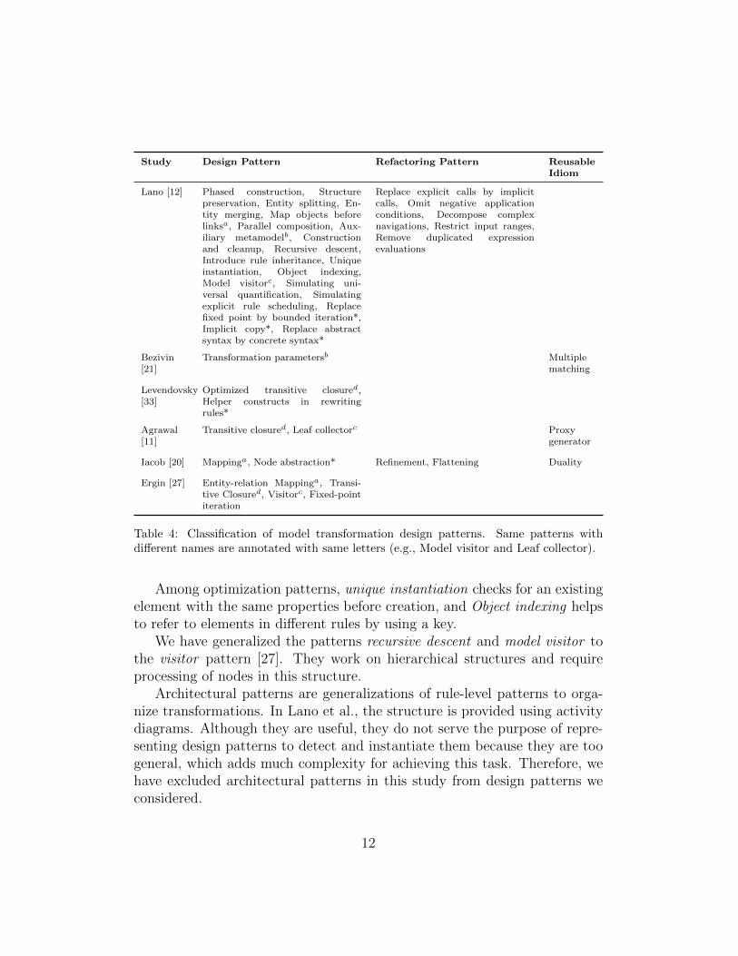
Study Design Pattern Refactoring Pattern ReusableIdiom
Lano [12] Phased construction, Structurepreservation, Entity splitting, En-tity merging, Map objects beforelinksa, Parallel composition, Aux-iliary metamodelb, Constructionand cleanup, Recursive descent,Introduce rule inheritance, Uniqueinstantiation, Object indexing,Model visitorc, Simulating uni-versal quantification, Simulatingexplicit rule scheduling, Replacefixed point by bounded iteration*,Implicit copy*, Replace abstractsyntax by concrete syntax*
Replace explicit calls by implicitcalls, Omit negative applicationconditions, Decompose complexnavigations, Restrict input ranges,Remove duplicated expressionevaluations
Bezivin[21]
Transformation parametersb Multiplematching
Levendovsky[33]
Optimized transitive closured,Helper constructs in rewritingrules*
Agrawal[11]
Transitive closured, Leaf collectorc Proxygenerator
Iacob [20] Mappinga, Node abstraction* Refinement, Flattening Duality
Ergin [27] Entity-relation Mappinga, Transi-tive Closured, Visitorc, Fixed-pointiteration
Table 4: Classification of model transformation design patterns. Same patterns withdifferent names are annotated with same letters (e.g., Model visitor and Leaf collector).
Among optimization patterns, unique instantiation checks for an existingelement with the same properties before creation, and Object indexing helpsto refer to elements in different rules by using a key.
We have generalized the patterns recursive descent and model visitor tothe visitor pattern [27]. They work on hierarchical structures and requireprocessing of nodes in this structure.
Architectural patterns are generalizations of rule-level patterns to orga-nize transformations. In Lano et al., the structure is provided using activitydiagrams. Although they are useful, they do not serve the purpose of repre-senting design patterns to detect and instantiate them because they are toogeneral, which adds much complexity for achieving this task. Therefore, wehave excluded architectural patterns in this study from design patterns weconsidered.
12
Replace fixed point by bounded iteration is a language-specific feature, forexample using FRules instead of SRules in MoTif [7]. FRule matches therule’s pre-condition at the beginning, therefore executing the rule for a fixednumber of times, whereas SRule matches the pre-condition in each iterationand works as long as the rule is applicable on the model. Implicit copy and re-placing abstract by concrete syntax are language-specific patterns. However,they provide useful features to have in an MTL, thus can be generalized andpromoted to design patterns.
We identified five patterns from Lano et al.[12] that are in fact refactor-ing patterns: Replace explicit calls by implicit calls, Omit negative applica-tion conditions, Decompose complex navigations, Restrict input ranges, andRemove duplicated expression evaluations. All of these patterns require atransformation to exist (as stated in their application condition) in order tooptimize specific features of the transformation. In addition, some of thepatterns proposed by Lano et al. are anti-patterns (i.e., depicts how not todo things), such as entity merging and entity splitting.
Bezivin [21]’s transformation parameters is a design pattern which wegeneralize to “auxiliary metamodel.” Multiple matching is a feature of theATL transformation language, therefore it is a reusable idiom.
Optimized transitive closure by Levendovszky [33] is a design pattern thatcan be identified in some other studies [11, 27] and also in this paper. Helperconstructs in rewriting rules is considered a design pattern, because creatingtraceability links can be reused in various MTLs.
Agrawal et al.’s [11] leaf collector is a visitor design pattern and proxygenerator idiom is considered a reusable idiom because it is specific to dis-tributed systems modeling languages.
We generalize Iacob et al.’s [20] mapping pattern in this paper to anEntities before relations pattern. Node abstraction can be carried out to be adesign pattern because it proposes a generic solution to identify some specificnodes. Refinement and flattening requires some input transformation andoptimizes the structure of the rules, therefore they are refactoring patterns.Duality is a reusable idiom to convert edges to nodes in a data flow.
Finally, all patterns in Ergin et al. [27] are design patterns designed forthe sake of this study.
4. A Unified Template for Model Transformation Design Patterns
This section defines the template to use when describing a MTDP.
13
4.1. The Unified Template
According to the feedback gathered in the survey in Section 2, althoughDelTa is a good candidate to describe a design pattern, it is not sufficientalone. A more complete description similar to GoF [10] design patterns wassuggested. As shown in Section 3, there is no agreement on how to rep-resent model transformation design patterns. Different studies have useddifferent fields to represent a design pattern, e.g., applicability, benefits, andstructure. Table 5 depicts the correspondences between existing proposalsfor model transformation design pattern templates. In addition, there is nocommon language that provides the structure of a model transformation de-sign pattern, analogous to how UML is used in representing the structures ofobject-oriented design patterns. Therefore, we propose to unify the existingdesign pattern representation templates and improve them with the appro-priate language (i.e., DelTa) to define the structure of each design pattern.The middle columns in Table 5 show which fields are used in different studiesto represent design patterns, along with their equivalents with the templateused in GoF in the last column. After analyzing all different notations andtemplates used in existing approaches, we propose to merge the respectivefields as a unified template shown in the first column. They are mostly in-fluenced by Lano et al. [12] since it was the most complete and thoroughtemplate in the literature. In the unified template, a design pattern consistsof the following fields:
� Summary: a short description of the design pattern that usually givesthe outline of the other fields in a few sentences.
� Application Conditions: pre-conditions on the context of use of thepattern. The conditions can be either pre-conditions on the metamodelor constraints over the transformation. This is usually expressed in thesame language as the solution field.
� Solution: generic solution to the problem the design pattern addresses.The structure of the solution is expressed in DelTa.
� Benefits: advantages of applying the design pattern. The benefitscan either be measurements with respect to some quality criteria orimprovements on some features of the transformation.
� Disadvantages: pitfalls of applying the design patterns. The disad-vantages can again be measurements with respect to some criteria.
14
� Examples: concrete application of the design pattern in a real con-text. The example is implemented in a specific model transformationlanguage.
� Implementation: discussion providing guidelines and hints on howto implement the design pattern in various transformation languages.
� Related patterns: correlation of the pattern with other patterns.This relation may be specialization, generalization, sequence, grouping,alternatives, or others.
� Variations: different versions of the pattern. This can either be withsmall tweaks or other alternative representations of the pattern.
15

Un
ified
Tem
pla
teB
eziv
in[2
1]
Leven
dov-
sky
[33]
Agra
wal
[11]
Iacob
[20]
Lan
o[1
2]
Erg
in[3
4]
GoF
Mean
ing
Su
mm
ary
Mot
ivat
ion
Mot
ivat
ion
Mot
ivat
ion
Goa
lS
um
mar
yM
otiv
atio
nIn
tent
Mot
ivat
ion
Mot
ivat
ion
Ap
pli
cati
onC
ond
itio
nA
pp
lica
bi-
lity
Ap
pli
cab
i-li
tyA
pp
lica
bi-
lity
Ap
pli
ca-
tion
Con
di-
tion
s
Ap
pli
cab
i-li
tyA
pp
lica
bi-
lity
Sol
uti
onS
olu
tion
Str
uct
ure
Str
uct
ure
Sp
ecifi
cati
onS
olu
tion
Str
uct
ure
Str
uct
ure
Par
tici
pan
ts
Ben
efits
Con
sequ
en-
ces
Con
sequ
en-
ces
Ben
efits
Ben
efits
Con
sequ
en-
ces
Dis
adva
n-
tage
sL
imit
atio
ns
Dis
adva
n-
tage
s
Exam
ple
sK
now
nU
ses
Kn
own
Use
sE
xam
ple
Ap
pli
ca-
tion
and
Exam
ple
s
Exam
ple
sK
now
nU
ses
Sam
ple
Cod
e
Imp
lem
enta
-ti
onIm
ple
men
ta-
tion
Imp
lem
enta
-ti
onV
aria
tion
sV
aria
tion
sV
aria
tion
sV
aria
tion
s
Rel
ated
Pat
tern
sR
elat
edP
atte
rns
Rel
ated
Pat
tern
s
Tab
le5:
Com
pari
son
of
fiel
ds
for
des
ign
patt
ern
des
crip
tion
16
4.2. Design Pattern Language for Model Transformations
Below, we define the language we have created , DelTa, to express the so-lution field of the unified template. DelTa is a neutral language, independentfrom any MTL. It is designed to define design patterns for model transforma-tions, hence it is not a language to define model transformations. We couldhave used an existing MTL as a notation for DelTa, however our need is anotation that expresses how elements within a rule are related and how rulesare related with each other. In this respect, DelTa offers concepts borrowedfrom most MTLs, abstracts away concepts specific to a particular MTL, andadds concepts to more easily describe design patterns. This is analogous tohow Gamma et al. [10] used UML class, sequence and state diagrams to definedesign patterns for object-oriented languages. In the following, we describethe abstract syntax, concrete syntax, and informal semantics of DelTa. Wealso compare DelTa with existing similar purpose languages.
4.2.1. Abstract Syntax
ModelTransformationDesignPattern
name : String
Transformation
UnitRelation
Pattern
Metamodel
Transformation
Unit
DesignPatternElementAnnotation
note : String
1..* 1..* 1..*
*
TransformationUnit
Rule
Action
Constraint
NegativeConstraint
PseudoUnit
name : String
START
END
result : boolean
Expression
Variable
exists : boolean
name : String
*
1
0..1
operatesOn*
declarations*
DesignPattern
Element
ForbiddenConstraint*
group : int
TransformationUnitRelation
TransformationUnit
1
condition
Decision
1
success
1
fail
Sequence
source
target
1 1
Choice
PatternMetamodel
Variable
Type
name : String
Trace Element
RelationEntity
1source 1target 1
*
Tag
name : String
negation : boolean
ConditionTag
ActionTag
Pro�le
name : String
description : String
1
1
*
1
source1
target1
2..*
isExhaustive : boolean
NoSched
2..*
Parallel
2..*
name : String
name : String
Figure 1: DelTa Metamodel
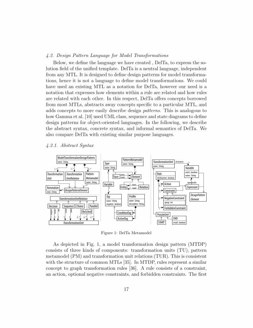
As depicted in Fig. 1, a model transformation design pattern (MTDP)consists of three kinds of components: transformation units (TU), patternmetamodel (PM) and transformation unit relations (TUR). This is consistentwith the structure of common MTLs [35]. In MTDP, rules represent a similarconcept to graph transformation rules [36]. A rule consists of a constraint,an action, optional negative constraints, and forbidden constraints. The first
17
three correspond to the usual left-hand side (LHS), right-hand side (RHS)and negative application conditions (NACs) in graph transformation, respec-tively. A constraint is the precondition of the rule. A negative constraintdefines the pattern that shall not be present, and a forbidden constraint onlyhas a symbolic meaning that specifically says the elements shall not existin the concrete transformation. Elements belong to a specific negative con-straint group when multiple negative constraints are needed. Other thanthese two, a regular constraint, which can also be considered as a positiveconstraint, defines the pattern that must be present in the model. The ac-tion defines the changes to be performed on the constraint (e.g., creation,deletion, or update).
PMs and variables form the participants collaborating in a design pattern.There are two types for variables: an element from the pattern metamodelor a trace. The PM is a label to distinguish between elements from differ-ent metamodels, since a MTDP is independent from the source and targetmetamodels used by the concrete model transformation. When implementinga MTDP, the pattern metamodel should not be confused with the originalmetamodel of the source and/or target models of a transformation, but ide-ally be implemented by their ramified version [37]. Given the metamodel ofa modeling language, ramification produces two metamodels, one to be usedas the type model of the pre-condition pattern of a transformation rule andanother for the post-condition pattern. For example, the former is used toperform queries on the input model of the transformation and the latter isused to perform updates to produce the output model. Metamodel elementsare abstracted to entities and relations. All variables are strongly typed.Tags are of two kinds: either a condition tag to be used in constraints or anaction tag to be used in actions. When implementing a MTDP, the use oftags may require to extend the original or ramified metamodels with addi-tional attributes. Traceability links are crucial in MTLs but, depending onthe language, they are either created implicitly or explicitly by a rule. InDelTa, we opted for the latter, which is more general, in order to require themodel engineer to take into account traceability links in the implementation.
As surveyed in [35], different MTLs have different flavors of TUs. Forexample, in MoTif, an ARule applies a rule once, an FRule applies a rule onall matches found, and an SRule applies a rule recursively as long as thereare matches. Another example is in Henshin [6] where rules with multi-nodeelements are applied on all matches found. Nevertheless, all MTLs offer atleast a TU to apply a rule once or recursively as long as possible, where we
18

adopt the latter with an isExhaustive attribute in the rule. All other flavorsof TUs can be expressed in TURs as demonstrated in [35].
As surveyed in [7, 4], in any MTL, rules are subject to a scheduling policy,whether it is implicit or explicit. For example, AGG [38] uses layers, MoTifand VMTS [39] use a control flow language, and GReAT defines causalityrelations between rules. As shown in [40], it is sufficient to have mechanismsfor sequencing, branching, and looping in order to support any schedulingoffered by a MTL. This is covered by the five TURs of DelTa: Sequence,Choice, Parallel, Decision, and NoSched that are explained in Section 4.2.3.PseudoUnits mark the beginning and the end of the scheduling part of adesign pattern.
Finally, annotations can be placed on any design pattern element in orderto give more insight to the reader on the particular design pattern element.
4.2.2. Concrete Syntax
initiate checkFixedPoint
fail
success
fail
success
Fixed Point
Iteration(mm) mm
entity1mark
mm
entity2mark
mm
elementToDeletemarked
mm
�xedPointmarked
Modify
mm
elementToModifymarked
!modi�ed -> modify
mm
elementToCreate
Create
mm
anElementmarked
Delete
mm
anElement
1
n0
n0
1 23
5 6
7
8
9
10
11
12
13
14
15
16
4
Figure 2: A Sample Pattern in DelTa Concrete Syntax
We highlight the DelTa graphical concrete syntax through an examplein Fig. 2. A textual concrete syntax is also available in Appendix A. The
19

figure depicts the structure of the solution of a sample pattern we have mod-ified from Fixed-point iteration pattern to illustrate most of the elements.Therefore, it is not a real design pattern.
1. A design pattern has a name and takes as parameter the metamodelsinvolved in the pattern. In this example, the fixed-point iterationdesign pattern involves one metamodel designated by mm.
2. A design pattern consists of a collection of rules rendered as rectangularblocks with their name appearing on the top left. This pattern has fiverules: initiate, checkFixedPoint, Modify, Delete, and Create. Aconcrete transformation rule implementing this design pattern shouldhave at least these rules.
3. When a self loop symbol appears on the top left, the rule is set to beexhaustive. This means that the concrete transformation rule imple-menting it should be applied on all of its matches. This may require tohave more than one rule implementing this rule, for example to matchdifferent metamodel types.
4. The dashed rectangle labeled “1” on the top left represents a choiceblock. It states that at least one of the rules from this block should beimplemented in the concrete transformation.
5. We use a control flow notation to represent rule scheduling. The startnode (filled ball) indicates the initial rule of the design pattern.
6. Arrows between rule blocks indicate a predence order: the concretetransformation rule implementing the initiate rule should be performedbefore the one implementing the checkFixedPoint rule.
7. Rule ordering may depend on the outcome of a rule. In this case,a decision node determines the next rule based on whether a rule issuccessfully applied (matches are found) or not. For example, if aconcrete transformation rule implementing the checkFixedPoint rulesucceeds, the design pattern states that the transformation implement-ing it should terminate successfully (on a successful end node). Other-wise, the next rule to be applied should be one from the choice block.
8. The design pattern can also state that the concrete transformationimplementing it should terminate unsucessfully. For example, if noneof the concrete transformation rules implementing the rules within thechoice block are applicable, then the design pattern indicates that thetransformation is unsuccessful: in the design pattern, this means thata fixed-point is not reached.
20

9. DelTa rules have the minimal constraints and actions on elements ofthe metamodel that concrete transformation rules implementing themshould have. For example, in rule initiate, there is only one constraintstating that there must be a relation from an entity (entity1) to an-other entity (entity2). Both entities shall belong to the same meta-model (mm). In DelTa, we only reason about entities and relations,independent from specific metamodel types and relations. Entities arerepresented using a UML class notation and their metamodel appearson the top right.
10. Action tags, represented using UML attribute notation, indicate an ac-tion to be performed, by the concrete transformation rule implementingit, on the entity when stated in the imperative form. For example, en-tity1 has the mark action tag, meaning that this entity must be havebeen “marked” in some form at this step of the concrete transformation.
11. When stated as a past participle, it is a condition tag that the entitymust satisfy in the constraint of the rule. For example, fixedPoint hasthe marked condition tag, meaning that this entity must have been“marked” in a previous rule so that a fixed-point is reached.
12. The notation !modified → modify should be interpreted as if theentity elementToModify was not yet modified, then it should bemodified after the application of rule Modify.
13. Color coding of entities and relations inside the rules indicate whetherthey are part of the constraint or a type of action of the rule. Whiteelements form the minimal application pre-condition that a concretetransformation rule implementing it should have. Gray elements arethe minimal elements to be created in the concrete transformation rule.For example, the Create rule states that the concrete transformationrule implementing it should look for an entity that is marked and createa new entity elementToCreate and a relation to this entity.
14. Black elements are the minimal elements to be deleted in the con-crete transformation rule. For example, the Delete rule states thatthe concrete transformation rule implementing it should look for anentity elementToDelete that is marked and is the target of a relationfrom another entity. Then the rule should delete the entity element-ToDelete and the relation.
15. Elements can also participate in the negative application condition(NAC) of a DelTa rule. This is presented by labeling the elementwith the letter n followed by a number. A NAC indicates the pattern
21

that should not be found by the concrete transformation rule imple-menting it. For example, the Create rule states that the concretetransformation rule implementing it should create the relation and theentity elementToCreate only if elementToCreate is not alreadyconnected to the marked entity anElement, because these two ele-ments are annotated with n0.
16. Apart from entities and relations, traces are also types of elementsthat can be used in DelTa rules. They are represented as dashed linesbetween entities and/or relations. Just like other elements, they canbe created and deleted, or be part of the constraint of a rule.
The complete description of the graphical concrete syntax is also availablein Appendix B.
4.2.3. Informal Semantics
The semantics of MTDP rules is borrowed from graph transformationrules [36], but adapted for patterns. Informally, a MTDP rule is applicableif its constraint can be matched without any negative constraints. If it is ap-plicable, then the action must be performed. Conceptually, we can representthis by: constraint ∧ ¬neg1 ∧ ¬neg2 ∧ . . .→ action. Forbidden constraintsremove ambiguity in the pattern and are not in this representation becausethey can be achieved either by ignoring them in the generation or addingthem as a constraint to the model transformation language. The presence ofa negated variable (i.e., with exists=false) in a constraint means that itscorresponding element shall not be found. Since constraints are conjunctive,negated variables are also combined in a conjunctive way. Disjunctions canbe expressed with multiple negative constraints. Actions follow the exactsame semantics as the “modify” rules in GrGen.NET [5]. Variables presentin the action must be created or have their flags updated. A variable maybe assigned tags to pass elements between rules. Negated variables in anaction indicate the deletion of the corresponding element. Tags are used toeither update some elements or reuse some elements in other rules. This issimilar to pivot passing in MoTif [7] and GReAT [41], and parameter passingin Viatra [42]. A condition tag should be used as a verb in past tense formand an action tag should be used in imperative form. In the case these formsare the same, we distinguish between them by adding the word “did” at thebeginning of the condition tag, i.e., “set > didSet.”
MTDP rules are guidelines to the model engineer and are not meantto be executed. On one hand, the constraint (together with negative and
22

forbidden constraints) of a rule should be interpreted as maximal : i.e., aconcrete model transformation rule shall find at most as many matches asthe MTDP rule it implements. On the other hand, the action of a rule shouldbe interpreted as minimal : i.e., a concrete model transformation rule shallperform at least the modifications of the MTDP rule it implements. Thismeans that more elements in the LHS or additional NACs may be present inthe concrete model transformation rule and that it may perform more CRUDoperations. Furthermore, additional rules may be needed when implementinga MTDP for a specific application. Note that the absence of an action in arule indicates that we do not care about the actions of the rule.
The scheduling of the TUs of a MTDP must always begin with STARTand end with a number of ENDs. The Sequence has a source and a targetdefines the temporal order between two or more TUs regardless of their ap-plicability. The Choice is a group of rules that defines the non-deterministicchoice to apply one TU out of a set of TUs. The Parallel lets the rules insideto be applied in parallel. The Decision defines a conditional branching andapplies the TUs in the success or fail branches according to the application ofthe rule in the condition. Note that the Decision TUR can be used to defineloop structures. The last TUR is the NoSched, which means the schedulingof the rules contained in this TUR is not important, such as within a layerof rules in AGG.
The translation of DelTa models to concrete model transformations inspecific MTLs will give a more precise semantics by translation.
4.2.4. Comparison of DelTa with Existing Languages to Express Design Pat-terns
Guerra et al. [9] proposed a collection of languages to engineer modeltransformations and, in particular, for the design phase. They propose aformal workflow that keeps traces between the different phases in the collec-tion. Each phase involves the production of necessary models conforming tothe respective language. Rule diagrams (RD), which represent the languagethat automatically produces the implementation of the transformation, areused to describe the structures of the rules and their task in the low-levelimplementation phase. Like DelTa, RD is defined at a level of abstrac-tion that is independent from existing MTLs. Therefore, there are somesimilarities and differences between RD and DelTa. In RD, rules focus onmappings rather than constraints and actions in DelTa. The metamodel ofRD strictly specifies that the transformations are based on mapping models
23
received from the mapping phase of the collection. Therefore, there needsto be at least two metamodels involved in the transformation to map witheach other. However, they specify designs for both unidirectional and bidi-rectional rules. The scheduling of rules allows for sequencing and branchingin alternative paths based on a constraint, which is covered by DelTa. Theexecution flow of RD supports sequencing rules, branching in alternativepaths based on a constraint which is similar to the decision TUR in DelTa,or non-deterministically choosing to apply one rule which is similar to thechoice TUR. They also allow rules to explicitly invoke the application ofother rules. RD is inspired from QVT-R and ETL and is therefore moreeasily implemented in these languages.
Lano et al. [12] proposed TSPEC as the language to describe the structureof design patterns. The purpose of TSPEC is to formalize whole transforma-tions, whereas the purpose of DelTa is to represent an abstraction of snippetsof a transformation, i.e., transformation patterns. Whereas TSPEC usesmappings with constraints to represent rules in a transformation, DelTa pro-vides a metamodel structure that lets create any kind of relation within therules, including element mappings from source language to target language.TSPEC uses another metamodel, named language metamodel (LMM), torepresent the languages on which the transformations operate upon. Thisis similar to the pattern metamodel part of DelTa for precisely specifyingconstraints. In addition, DelTa has these features to help represent the de-sign patterns: explicit decision structure to identify the result of a rule interms of success and failure, choice and no scheduled structures to grouprules together. DelTa provides both a graphical and textual concrete syn-tax, whereas TSPEC only provides a textual syntax. In conclusion, we canstate that DelTa was designed intentionally from an engineering perspective,to help engineers to understand and implement patterns, and to generatetransformations from it, whereas TSPEC formalizes the effects of a transfor-mation and is used to analyze them.
5. Model Transformation Design Patterns
In this section, we apply the unified template to the identified modeltransformation design patterns. We only show three design patterns for thesake of readability and put the rest of them, including Lano’s design patterns,in Appendix C. In the implementation field, where language-specific imple-mentation details are provided, we illustrate each pattern with an example
24

implemented in an actual MTL. The goal here is to demonstrate applicabilityof the unified template and represent the solution of the design patterns inDelTa. Furthermore, we specify the category under which each pattern fallsaccording to the classification of Lano et al.
5.1. Entities Before Relations
This pattern falls under the “rule modularization” category.
� Summary: Entities before relations is one of the most commonly usedtransformation patterns in exogenous transformations to encode a map-ping between two languages. It creates the elements in a language cor-responding to elements from another language and establishes trace-ability links between the elements of source and target languages. Thispattern was originally proposed in [20].
� Application Conditions: The Entities before relations pattern isapplicable when we want to translate elements from one metamodelinto elements from another metamodel.
� Solution: The structure of the pattern is depicted in Fig. 3. The
src
sEnttrgt
tEntn0
src
sEnttrgt
tEnt
src
sEnt2trgt
tEnt2
n0
Entities Before Relations
(src,trgt)
n0
entityMapping
relationMapping
Figure 3: Entities before relations - Structure in DelTa
structure reads as follows. In the first rule, for each instance of entitiesin the source metamodel, if they do not have a corresponding targetentity, create the corresponding entity in the target metamodel. Thecorresponding entity is represented by a trace connection between thesource and target entities. Then in the second rule, relations are cre-ated between corresponding target entities, simulating their equivalentrelations in the source metamodel, again if the relation does not ex-ist. This ensures that first, all entities from the source are mapped toentities in the target and then, all relations between them are mapped.
25

� Benefits: With the help of traceability links, each element in thetarget language has a corresponding element in the source language.This improves debugging capabilities and error localization [28].
� Disadvantages: The pattern has no known disadvantages. However,the traceability links should be removed after the transformation isapplied.
� Examples: A typical example of Entities before relations pattern is inthe transformation from class diagram to relational database diagrams,where, for example, a class is transformed to a table, an attribute toa column, and the relation between class and attribute to a relationbetween table and column.
� Implementation:
Figure 4: Rules of Entities before relations pattern in ATL
The implementation of the Entities before relations pattern in ATL
26
is depicted in Fig. 4. It is applied to the class diagram to relationaldatabase transformation example. There are two rules that correspondto entityMapping: one for mapping classes to tables and one for map-ping attributes to columns. The relationMapping is implemented as theattrs2cols rule. In ATL, traceability links are either implicit and createdby the interpreter itself or modeled explicitly as a separate class con-necting the source and target elements. We opted for the latter in thisimplementation. Due to the causality relation between the rules, thisATL transformation first applies rules class2table and attribute2column,then attrs2cols as stipulate in this design pattern.
� Related patterns: The pattern can be identified as a special case ofPhased Construction in Section Appendix C.3, where the phases are,first, the entities and, then, the relations.
� Variations: The mapping can be done in either many-to-one or one-to-many with respect to the relation between source and target meta-models.
5.2. Fixed-point Iteration
This pattern falls under the “optimization” category.
� Summary: Fixed point iteration is a pattern for representing a “do-until” loop structure. It solves the problem by modifying the inputmodel iteratively until a condition is satisfied.
� Application Conditions: This pattern is applicable when the prob-lem can be solved iteratively until a fixed point is reached. Each iter-ation must perform the same modification on the model, possibly atdifferent locations: either adding new elements, removing elements, ormodifying attributes.
� Solution: The solution is depicted in Fig. 5. The pattern starts bymarking a predetermined group of entities in the initiate rule and checksif the model has reached a fixed-point (i.e., the condition encoded in theconstraint of the checkFixedPoint rule). If it has, the checkFixedPointrule may perform some action, e.g., marking the elements that satisfiedthe condition. Otherwise, the pattern modifies the current model bychoosing either create/modify/delete rules inside the Choice TUR. In
27

this rule, only one of the rules in the block are selected and the fixedpoint is checked again for a possible finding. If the rules in the blockfail, it means no fixed-point is found and the result is a failure. Thedeleted elements are depicted in black in the Delete rule.
initiate checkFixedPoint
fail
success
fail
success
Fixed Point
Iteration(mm) mm
element1mark
mm
element2mark
mm
elementToDeletemarked
mm
fixedPointmarked
Modify
mm
elementToModifymarkedmodify
mm
elementToCreate
Create
mm
anElementmarked
Delete
mm
anElement
1
Figure 5: Fixed-point Iteration - Structure in DelTa
� Benefits: The pattern helps to traverse the graph structure of theinput model. Therefore, it can be modified to fit into different graphtraversal algorithms.
� Disadvantages: The traversal of the graph occurs iteratively, whichhinders the parallelization opportunities of the model transformation.
� Examples: There are various applications of this pattern in differentfields. For example in [34], we showed how to solve three problems withthis pattern: computing the lowest-common ancestor of two nodes in adirected tree, finding the equivalent resistance in an electrical circuit,and finding the shortest path using Dijkstra’s algorithm are some ofthem.
� Implementation: Fig. 6 shows the implementation of the LCA from [34]
28

LinkToAncestor
:GetLCA?
C
A B
GetLCA
X
Y
X
YBB
X
Y
X
YA A
Rules: Scheduling:
LinkToSelf
,A A
B B
X X
LinkToParent
A A
X X
B B,
,
Figure 6: Rules and Scheduling in MoTif
in MoTif using the fixed point iteration pattern. The initiate rule is ex-tended to create traceability links on the input nodes themselves withthe LinkToSelf rules and with their parents with the LinkToParent rules.The GetLCA rule implements the checkFixedPoint rule and tries to findthe LCA of the two nodes in the resulting model following traceabilitylinks. This rule does not have a RHS but it sets a pivot to the result forfurther processing. The LinkToAncestor rules implement the iterate ruleby connecting the input nodes to their ancestors. The MoTif controlstructure reflects exactly the same scheduling of the pattern.
� Related patterns: The iteration of the model with create/modi-fy/delete elements can be done with the phased construction designpattern. Also, auxiliary metamodel elements are used in order to tracethe elements.
� Variations: The pattern can be used to reduce the transformation byusing delete-only rules, or augment the transformation by using create-only rules.
5.3. Execution by Translation
This pattern falls under the “optimization” category.
� Summary: To execute a domain-specific language (DSL), we often re-fer to some other languages that have well-defined semantics and easyto execute. This saves the time and effort of the model engineer to
29
write an executor from scratch for the DSL and standardizes the exe-cution. With this pattern, the DSL is mapped to another intermediatelanguage. Then, this language is simulated and the corresponding DSLelements are modified accordingly to show the animation.
� Application Conditions: The pattern is applicable when we want toexecute a DSL using another DSL that has well-defined semantics.
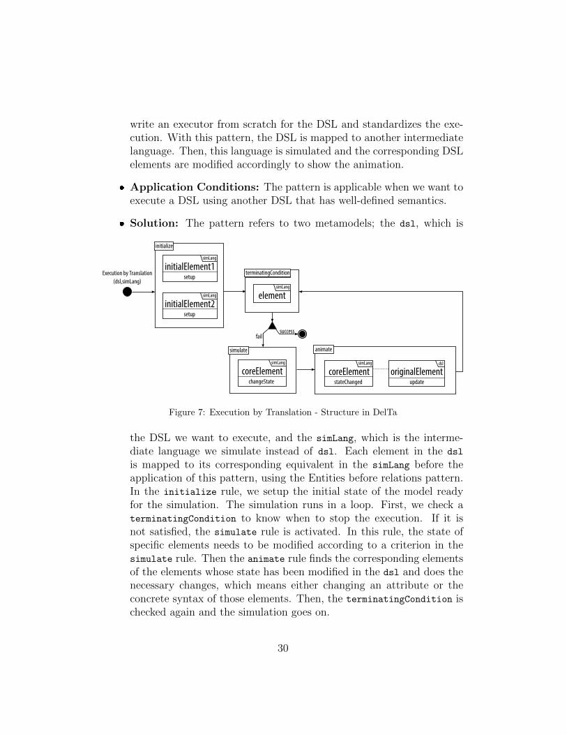
� Solution: The pattern refers to two metamodels; the dsl, which is
Execution by Translation
(dsl,simLang)
initialElement1setup
initialize
terminatingCondition
simLang
initialElement2setup
simLang elementsimLang
successfail
coreElementchangeState
simulate
simLang
animate
coreElementstateChanged
simLang
originalElementupdate
dsl
Figure 7: Execution by Translation - Structure in DelTa
the DSL we want to execute, and the simLang, which is the interme-diate language we simulate instead of dsl. Each element in the dsl
is mapped to its corresponding equivalent in the simLang before theapplication of this pattern, using the Entities before relations pattern.In the initialize rule, we setup the initial state of the model readyfor the simulation. The simulation runs in a loop. First, we check aterminatingCondition to know when to stop the execution. If it isnot satisfied, the simulate rule is activated. In this rule, the state ofspecific elements needs to be modified according to a criterion in thesimulate rule. Then the animate rule finds the corresponding elementsof the elements whose state has been modified in the dsl and does thenecessary changes, which means either changing an attribute or theconcrete syntax of those elements. Then, the terminatingCondition ischecked again and the simulation goes on.
30

� Benefits: The main benefit is not needing a separate execution driverfor various DSLs. A well-known, well-analyzed executor can be reusedfor different DSLs.
� Disadvantages: The elements of the DSL should be mapped to thesimulation language perfectly. Otherwise, there will be inconsistenciesin the execution.
� Examples: In [37], Kuhne et al. execute finite state automata (FSA)by translating to Petri Nets (PN). As they simulate the PN, they ani-mate the FSA accordingly. In [43], we have defined a translation fromactivity diagram (AD) to PN, and simulated the PN to animate theAD. De Lara and Vangheluwe mapped a production system DSL toa PN and used the PN for the dynamic behavior of the productionsystem [44].
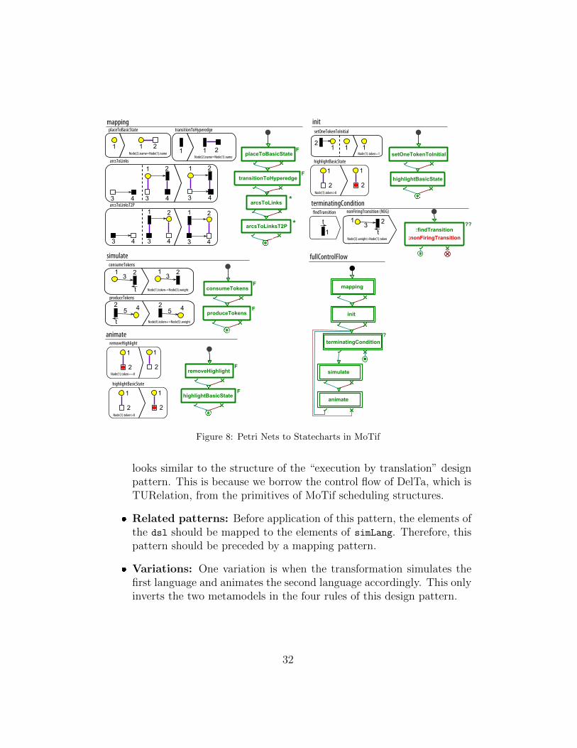
� Implementation: An implementation in MoTif is depicted in Fig. 8.The example maps PN to statecharts (SC) and uses the PN to simu-late the SC. We only map the basic states and hyperedges in the SCfor simplicity, but the advanced transformation can be found in [45].The mapping part maps the places to basic states and transitions to hy-peredges with the placeToBasicState and the transitionToHyperedge
rules. Then, the arcs of the PN are mapped to links in the SC with thearcsToLinks and the arcsToLinksT2P rules. After mapping, the init
part does the same job as in the previous examples. The setOneTokenTo-Initial rule puts one token to the place of the initial node, which is theplace without an incoming transition in this case. Then, the highlight
rule highlights the current state. MoTif supports pivots to pass thematched elements between rules. Therefore, this makes it easier to geta transition and check if it is firing or not by just passing it to theother rule, without the need for another attribute. A special complexquery rule in MoTif makes it possible to get the firing transition withthe help of the findTransition and the nonFiringTransition rules.The findTransition gets one transition, assigns a pivot to it and thenonFiringTransition checks if this transition is blocked or not. If thepattern is matched, that means it is not a firing transition and the ruletries another transition. The simulate and the animate part of therules are the same as the previous examples, as they are basic PN sim-ulation rules. In the fullControlFlow structure, one can realize that it
31
mappingplaceToBasicState
1 1 2
Node(2).name=Node(1).name
transitionToHyperedge
1 1 2
Node(2).name=Node(1).namearcsToLinks
1 2
3 4
1 2
3 43 4
arcsToLinksT2P
1 2
3 4
1 2
3 43 4
initsetOneTokenToInitial
1 1Node(1).token=1
12
terminatingCondition
highlightBasicState
1
2
Node(1).token>0
1
2
findTransition
1
t 1 2
nonFiringTransition (NEG)
t
3
Node(3).weight>Node(1).token
simulate
produceTokens
42
t
5
Node(4).token+=Node(5).weight
42
5
consumeTokens
1 2
t
31 23
Node(1).token-=Node(3).weight
animateremoveHighlight
1
2
Node(1).token==0
1
2
highlightBasicState
1
2
Node(1).token>0
1
2
arcsToLinksT2P *
placeToBasicStateF
transitionToHyperedgeF
arcsToLinks*
setOneTokenToInitial
highlightBasicState
:findTransition??
:nonFiringTransition
mappingF
consumeTokens
produceTokensF
FremoveHighlight
highlightBasicStateF
init
terminatingCondition
?
simulate
animate
fullControlFlow
Figure 8: Petri Nets to Statecharts in MoTif
looks similar to the structure of the “execution by translation” designpattern. This is because we borrow the control flow of DelTa, which isTURelation, from the primitives of MoTif scheduling structures.
� Related patterns: Before application of this pattern, the elements ofthe dsl should be mapped to the elements of simLang. Therefore, thispattern should be preceded by a mapping pattern.
� Variations: One variation is when the transformation simulates thefirst language and animates the second language accordingly. This onlyinverts the two metamodels in the four rules of this design pattern.
32
6. Design Pattern-driven Model Transformation Development
The survey in Section 2 showed there is no systematic development pro-cess that model engineers follow when they want to solve a problem usingmodel transformation, even if some preliminary processes have been proposedin the past [9, 46]. On the other hand, design patterns let model engineersreuse high-quality designs that have been proven to solve specific recurringproblems by experienced practitioners. Therefore, there should be a way tolet model engineers take advantage of these patterns when designing a modeltransformation. To remedy the ad-hoc design and implementation of modeltransformations (which consists of the large majority of projects in our pilotsurvey), we propose a design process to guide model engineers in their designchoices by reusing design patterns in their implementations. The prototypewe implemented showcases how this can be achieved by automatically in-stantiating patterns in the MTL of their choice using template-based codegeneration.
6.1. Process for designing and implementing model transformations
We describe the process model transformation engineers are encouragedto follow when they want to use design patterns in their transformation.Budinsky et al. [47] generated actual code from object-oriented design pat-terns and let the model engineers adapt the code to the rest of their appli-cation and further modify to add necessary application-specific details. Wehave adapted their approach to model transformation design patterns.
6.1.1. Problem identification
The very first step is to analyze the problem at hand and make sure thatrule-based model transformation is the correct paradigm to solve the prob-lem. The choice of the appropriate model transformation approach greatlyinfluences the accidental complexity of the solution and thus the efficiencyof the development [48]. A divide-and-conquer methodology has proven tobe often useful to solve problems using model transformation because of themodularity of the rules and control structure this paradigm offers [49]. Largerproblems can be decomposed into simpler sub-problems, until a solution us-ing a design pattern becomes apparent.
6.1.2. Pattern selection
For each transformation (sub-)problem, the model engineer selects a modeltransformation design pattern that is best fit to solve it, as widely practiced
33

for object-oriented design pattern selection [50, 51]. This requires modelengineers to scan through the design pattern catalog. However, senior andrecurrent model engineers can only focus on the summary and applicationcondition fields. This is an important step, because correctly implementingan inappropriate design pattern will certainly lead to a bad design [17]. Oneshould not assume there is a design pattern for every problem. However, if adesign pattern can solve the problem at hand, then it is highly recommendedto use it. If not, one possibility is to craft a solution in DelTa. The DelTamodel helps the model engineer focus on the design of the solution so thatthey are not encumbered with the details of an implementation in a specificMTL.
6.1.3. Adaptation to problem
Design patterns are described in a generic way to be independent fromthe specific context of their application. Thus, the model engineer mustadapt the pattern to the problem at hand. This includes customizing theparticipants of the pattern in the DelTa model: metamodels and elementsinvolved, or adapting the semantics of tags (e.g., the example in Section 5.1uses class diagrams as source metamodel). The adaptation step can alsoinclude investigating variants of the pattern, focusing on the variation fields(e.g., the mapping in Section 5.3 uses many-to-one instead of one-to-onemapping).
6.1.4. Implementation and refinement
At this point, the model engineer first implements as-is the customizedpattern from the previous step. The choice of the MTL may require more ef-fort at this step (e.g., if the MTL does not support explicit control scheduling,the model engineer also has to adopt the Simulating Explicit Rule Schedulingdesign pattern from Appendix C.3.9 in their transformations). Nevertheless,this step may be automated by generating a model transformation excerptthat implements the pattern [52]. Then, being a generic solution to theproblem, the implemented design pattern needs to be further refined to thespecific problem. At the rule level, one can add more actions to performor expand the constraint of rules (e.g., the model engineer has to add moreconstraints to provide the logic for selecting the starting entity in the Visitordesign pattern in Appendix C.1). Another refinement may be to add furtherrules to deal with different types (following the top-down phased construc-tion in Appendix C.3.2) or to modularize the pattern (following the entity
34
splitting in Appendix C.3.5 and entity merging in Appendix C.3.6). Moreconcrete examples can be found in [31].
6.1.5. Integration
The implemented pattern should be integrated carefully with the rest ofthe model transformation. Further customizations or modification may berequired (e.g., the init and mapping phase of Petri Net to statecharts trans-formation in Fig. 8). In addition, micro-architectures can also be constructedby applying patterns in combination with each other [18].
6.1.6. Beyond the process
This process is iterative and incremental since it can be repeated as longas sub-problems can be solved using design patterns. It can also be integratedin the transition between the design and implementation phases of well-known software development processes that must be followed in the project(e.g., Unified Process [53] or Agile Method [54]). This process does notassume there is necessarily a design pattern to solve the (sub-)problem athand.
6.2. Benefits of a Design Pattern-driven Methodology
The core object-oriented design patterns have already demonstrated mul-tiple benefits [55]. These include: (1) encapsulating the techniques to solvesimilar problems, (2) proposing a vocabulary that various domain expertscan understand, and (3) improving the ability to document software by ab-stracting away the language details [55]. In the proposed design patterndriven development approach, we try to preserve these benefits as much aspossible. We have observed that DelTa can assist in supporting the under-standing of solution and documentation of modeling concerns. In the stepsof our methodology, a model engineer can traverse existing patterns to finda solution to a specific problem by studying similar solutions. The auto-matic generation possibility directly from DelTa aids the model engineer byremoving irrelevant implementation details and avoiding accidental complex-ities [56]. However, these benefits also result in several challenges. Studyingthe existing design patterns may also require additional effort, which addsadditional time to solve a model transformation problem. After design pat-terns become more familiar by the domain experts, it is expected that thisissue becomes less challenging.
35
Use
rTo
ol
Select designpattern
Design pattern
Populateparameters
Setparameters
Parameters
Select modeltransformation
language
Loadparameters
Loadtemplate
Model transformationlanguage
Generate transformation
Transformation
yes
More designpatterns?
no
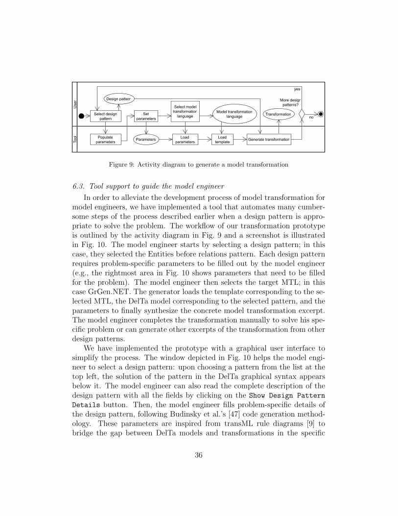
Figure 9: Activity diagram to generate a model transformation
6.3. Tool support to guide the model engineer
In order to alleviate the development process of model transformation formodel engineers, we have implemented a tool that automates many cumber-some steps of the process described earlier when a design pattern is appro-priate to solve the problem. The workflow of our transformation prototypeis outlined by the activity diagram in Fig. 9 and a screenshot is illustratedin Fig. 10. The model engineer starts by selecting a design pattern; in thiscase, they selected the Entities before relations pattern. Each design patternrequires problem-specific parameters to be filled out by the model engineer(e.g., the rightmost area in Fig. 10 shows parameters that need to be filledfor the problem). The model engineer then selects the target MTL; in thiscase GrGen.NET. The generator loads the template corresponding to the se-lected MTL, the DelTa model corresponding to the selected pattern, and theparameters to finally synthesize the concrete model transformation excerpt.The model engineer completes the transformation manually to solve his spe-cific problem or can generate other excerpts of the transformation from otherdesign patterns.
We have implemented the prototype with a graphical user interface tosimplify the process. The window depicted in Fig. 10 helps the model engi-neer to select a design pattern: upon choosing a pattern from the list at thetop left, the solution of the pattern in the DelTa graphical syntax appearsbelow it. The model engineer can also read the complete description of thedesign pattern with all the fields by clicking on the Show Design Pattern
Details button. Then, the model engineer fills problem-specific details ofthe design pattern, following Budinsky et al.’s [47] code generation method-ology. These parameters are inspired from transML rule diagrams [9] tobridge the gap between DelTa models and transformations in the specific
36

Figure 10: Design pattern generator tool
MTL: e.g., metamodel-specific type names. The editable parameter list isgenerated automatically from each DelTa model.
6.3.1. Implementation using MDE practices
Following MDE practices, we have adopted the Eclipse Modeling Frame-work (EMF) [57] to create a domain-specific modeling environment for DelTa.With this modeling environment, we populated the catalog with design pat-tern structures conforming to the DelTa metamodel of Fig. 1. This alsogives the opportunity to define new design patterns or simply start designinga solution to a model transformation problem directly using DelTa. We im-plemented the generation of model transformations using the template-basedmodel-to-text transformation tool Xpand5. This is therefore a higher-ordertransformation [58]. In order to show the applicability of our approach, wesupport two different MTLs: GrGen.NET and Henshin. We choose thesetwo languages because they are exogenous [4], which has different input andoutput metamodels. The choice of these two languages also demonstratesthe breadth of applicability of DelTa in various MTLs.
5https://eclipse.org/modeling/m2t/?project=Xpand
37

6.3.2. Generation of concrete model transformations
We opted for a template-based code generation approach, as commonlypracticed in MDE, to reduce the development effort for further design pat-terns and MTL support [4]. Only one template per MTL needs to be imple-mented, because a template depends only on the metamodel of DelTa. Thetemplate can be used to generate any design pattern from the catalog, aswell as new ones expressed in DelTa. In our case, we implemented Xpandtemplates such that the interpreter takes as input a DelTa model in EMFand generates textual code that can be executed by a model transformationtool. Listing 1 depicts the general algorithm of the template to follow. Itstarts from the root node of the design pattern and traverses all elementshierarchically. Although this is a generic pseudo-template, small variationsin the algorithm are necessary depending on the target transformation lan-guage. For example, when generating GrGen.NET transformation code, thetemplate needs to create two files, one for the scheduling and another onefor the rules, as in lines 2 and 19. however, only a single file is needed togenerate the Henshin Ecore model. An additional step is required after eachrule expansion (i.e., after line 17), where corresponding rule elements aremapped between the constraint and action to indicate that they refer to thesame element.
Listing 1: General algorithm of a template to generation transformation code
1 Expand ‘ Model Transformation Design Pattern ’2 Create f i l e f o r r u l e s3 Expand ‘ Pattern Metamodel ’4 Expand ‘ Transformation Unit ’5 Expand ‘ Rule ’6 Expand ‘ Annotation ’7 Expand ‘ Constra ints ’8 Expand ‘ Var iable ’9 Expand ‘ Annotation ’
10 Expand ‘ Trace ’11 Expand ‘ Entity ’12 Expand ‘ Relat ion ’13 Expand ‘Tag ’14 Expand ‘ Negat ive Constra ints ’15 Expand ‘ Var iable ’ under negat ive part o f the r u l e16 Expand ‘ Actions ’17 Expand ‘ Var iable ’ under ac t i on part o f the r u l e18 Expand ‘ Start ’19 Create f i l e f o r s chedu l ing
38
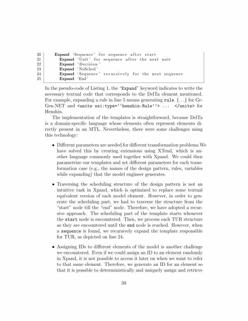
20 Expand ‘ Sequence ’ f o r sequence a f t e r s t a r t21 Expand ‘ Unit ’ f o r sequence a f t e r the next un i t22 Expand ‘ Dec is ion ’23 Expand ‘ NoSched ’24 Expand ‘ Sequence ’ r e c u r s i v e l y f o r the next sequence25 Expand ‘End ’
In the pseudo-code of Listing 1, the “Expand” keyword indicates to write thenecessary textual code that corresponds to the DelTa element mentioned.For example, expanding a rule in line 5 means generating rule {. . .} for Gr-Gen.NET and <units xsi:type=‘‘henshin:Rule’’> ... </units> forHenshin.
The implementation of the templates is straightforward, because DelTais a domain-specific language whose elements often represent elements di-rectly present in an MTL. Nevertheless, there were some challenges usingthis technology:
� Different parameters are needed for different transformation problems.Wehave solved this by creating extensions using XTend, which is an-other language commonly used together with Xpand. We could thenparametrize our templates and set different parameters for each trans-formation case (e.g., the names of the design pattern, rules, variableswhile expanding) that the model engineer generates.
� Traversing the scheduling structure of the design pattern is not anintuitive task in Xpand, which is optimized to replace some textualequivalent version of each model element. However, in order to gen-erate the scheduling part, we had to traverse the structure from the“start” node till the “end” node. Therefore, we have adopted a recur-sive approach. The scheduling part of the template starts wheneverthe start node is encountered. Then, we process each TUR structureas they are encountered until the end node is reached. However, whena sequence is found, we recursively expand the template responsiblefor TUR, as depicted on line 24.
� Assigning IDs to different elements of the model is another challengewe encountered. Even if we could assign an ID to an element randomlyin Xpand, it is not possible to access it later on when we want to referto that same element. Therefore, we generate an ID for an element sothat it is possible to deterministically and uniquely assign and retrieve
39
its value based on the context of the element. For example, if anelement of type T has to appear in the right-hand side of a rule R
(i.e., post-condition of a graph transformation rule like in GrGen.NETand Henshin), its ID will be of the form R RHS T. Whenever we wantto refer to that same element in the right-hand side, we can then easilyrecreate and reuse this ID.
An example output of the this tool is depicted in Fig. C.21. In thatexample, the transformation, that is using Visitor pattern, is automaticallygenerated and then refined for the “class depth level” problem. The generatedtransformation model conforms to a specific MTL. We use the respectivelanguage compilers to establish this conformance check. For GrGen.NET,the verification consists of running the compiler with a command line. ForHenshin, it consists of opening the model with the Henshin model editor thatcan only open valid models. We have successfully verified that all designpatterns are correctly generated and conform to their respective MTLs.
6.4. Application on a Real Example
In what follows, we illustrate how model transformation design patternsare applied on the case study from the Transformation Tool Contest 2013 [59]:transforming a Petri net (PN) model to a Statechart (SC) model. We ex-tend our original solution in MoTif [45] to execute the SC model using theunderlying PN model. The solution is summarized in Section 5.3 under theimplementation field. We solve this transformation problem following theprocess we proposed in Section 6.1.
6.4.1. Problem Identification
We choose to solve this case with a model transformation approach thatuses an explicit scheduling of graph transformation rules, such as MoTif [7].After analyzing the structure of each PN and SC, we propose to decomposethe transformation into the following sub-problems:
1. Initialization: elements in each PN are mapped to elements in eachSC.
2. AND Reduction: AND states are created in each SC for a specialset of places in each PN.
3. OR Reduction: OR states are created in each SC for a special set oftransitions in each PN.
40

4. Control Flow: overall control flow that depicts the ordering of therules.
5. Simulation: execute each SC by simulating the corresponding PN.
6.4.2. Pattern Selection
We identify the most appropriate design pattern from the catalog foreach transformation sub-problem. In the initialization phase, elements aremapped by using the Entities before relations pattern. Some of thesemappings can be performed in parallel using the Parallel Compositionpattern. In order to keep a tracing relation between SC and PN elements,we use the Auxiliary Metamodel pattern to create trace links. SC is a hier-archical structure, therefore, we use the Top-down Phased Constructionpattern to create AND and OR states in the reduction phases, i.e., createthe AND (OR) states first, then the sub-states within those. The reductionwill run for as long as the PN has a suitable scenario for reduction: thisrecursion is performed using the Fixed-point Iteration pattern. Selectingthe correct part of the PN for reductions requires the reuse of objects previ-ously matched or created in other rules. Thus, we use the Object Indexingpattern. The overall simulation of the SC using the corresponding PN isensured using the Execution by Translation pattern.
6.4.3. Adaptation to Problem
For most of the previously identified design patterns, the source meta-model is a PN and the target metamodel is a SC. In addition, all the namesin the patterns should be adapted to represent the appropriate PN and SCstructures. For the initialization phase, we need a one-to-many variant ofthe Entities before relations pattern, because an element in a PN is mappedto two elements in a SC. No variation is needed for the remaining designpatterns.
6.4.4. Implementation and Refinement
We have implemented the problem in MoTif. Below, we highlight howeach of the previously adapted design patterns are implemented in the solu-tion. The complete final transformation is available in the report [45].
Entities Before Relations:. These rules map the elements of a PN to elementsin a SC while maintaining traceability links between the source and thetarget. In Fig. 11, the elements of a PN that are “place,” “transition,” and
41
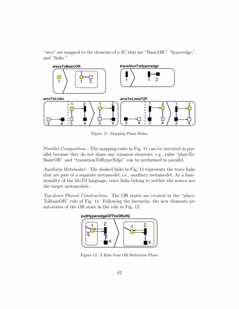
“arcs” are mapped to the elements of a SC that are “BasicOR,” “hyperedge,”and “links.”
placeToBasicOR
1 1
transitionToHyperedge
1 122
arcsToLinks
1 2
3 4
1 2
3 43 4
arcsToLinksT2P
1 2
3 4
1 2
3 43 4
Figure 11: Mapping Phase Rules
Parallel Composition:. The mapping rules in Fig. 11 can be executed in par-allel because they do not share any common elements; e.g., rules “placeTo-BasicOR” and “transitionToHyperEdge” can be performed in parallel.
Auxiliary Metamodel:. The dashed links in Fig. 11 represents the trace linksthat are part of a separate metamodel, i.e., auxiliary metamodel. As a func-tionality of the MoTif language, trace links belong to neither the source northe target metamodels.
Top-down Phased Construction:. The OR states are created in the “place-ToBasicOR” rule of Fig. 11. Following the hierarchy, the new elements aresub-states of the OR state in the rule in Fig. 12.
putHyperedgeOfTtoORofQ
1 2
4
1 2
4
tq
Figure 12: A Rule from OR Reduction Phase
42
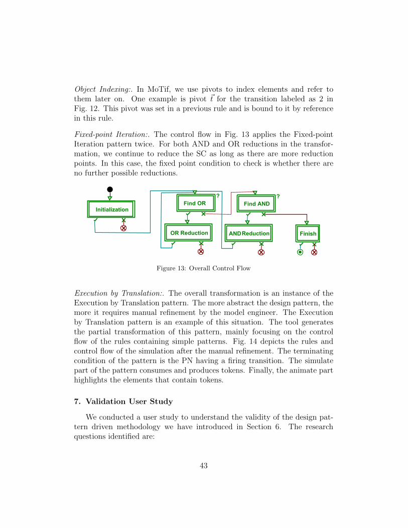
Object Indexing:. In MoTif, we use pivots to index elements and refer tothem later on. One example is pivot ~t for the transition labeled as 2 inFig. 12. This pivot was set in a previous rule and is bound to it by referencein this rule.
Fixed-point Iteration:. The control flow in Fig. 13 applies the Fixed-pointIteration pattern twice. For both AND and OR reductions in the transfor-mation, we continue to reduce the SC as long as there are more reductionpoints. In this case, the fixed point condition to check is whether there areno further possible reductions.
Initialization
Find OR
?
OR Reduction
Find AND
?
ANDReduction Finish
Figure 13: Overall Control Flow
Execution by Translation:. The overall transformation is an instance of theExecution by Translation pattern. The more abstract the design pattern, themore it requires manual refinement by the model engineer. The Executionby Translation pattern is an example of this situation. The tool generatesthe partial transformation of this pattern, mainly focusing on the controlflow of the rules containing simple patterns. Fig. 14 depicts the rules andcontrol flow of the simulation after the manual refinement. The terminatingcondition of the pattern is the PN having a firing transition. The simulatepart of the pattern consumes and produces tokens. Finally, the animate parthighlights the elements that contain tokens.
7. Validation User Study
We conducted a user study to understand the validity of the design pat-tern driven methodology we have introduced in Section 6. The researchquestions identified are:
43
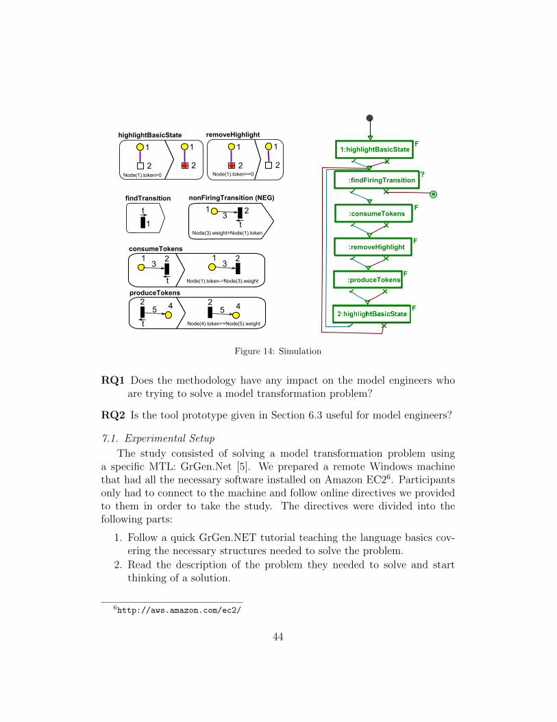
findFiringTransition:?
consumeTokens:F
produceTokens:F
highlightBasicState:F
removeHighlight:F
findTransition
1
t 1 2
nonFiringTransition (NEG)
t3
Node(3).weight>Node(1).token
consumeTokens
1 2
t
31 23
Node(1).token-=Node(3).weight
produceTokens
42
t
5
Node(4).token+=Node(5).weight
425
highlightBasicState
1
2Node(1).token>0
1
2
removeHighlight
1
2Node(1).token==0
1
2
1
F
Figure 14: Simulation
RQ1 Does the methodology have any impact on the model engineers whoare trying to solve a model transformation problem?
RQ2 Is the tool prototype given in Section 6.3 useful for model engineers?
7.1. Experimental Setup
The study consisted of solving a model transformation problem usinga specific MTL: GrGen.Net [5]. We prepared a remote Windows machinethat had all the necessary software installed on Amazon EC26. Participantsonly had to connect to the machine and follow online directives we providedto them in order to take the study. The directives were divided into thefollowing parts:
1. Follow a quick GrGen.NET tutorial teaching the language basics cov-ering the necessary structures needed to solve the problem.
2. Read the description of the problem they needed to solve and startthinking of a solution.
6http://aws.amazon.com/ec2/
44
3. Read the description of the design pattern driven methodology (seeSection 6.1).
4. Follow a tutorial on how to use the Design Pattern Generator tool (seeSection 6.3).
5. Solve the problem using the tool.
6. Complete a survey regarding their experience in the user study.
Participants had a two-hour time slots alloted to them with access toresources we provided them at any time. The problem to solve was a simpletranslation from C language structures connected with pointers to Java lan-guage classes connected with inheritance links and associations. The problemhad two parts. The first part was the translation so that the resulting Javamodel had classes with single inheritance only. The second part was thecomputation of depth levels of each class in the inheritance hierarchy. Thedepth level represents the number of classes between a class and its furthestancestor. We provided them with an initial project with simplified metamod-els of C and Java, along with the tools necessary for training purposes. Thepost-survey consisted of 5 questions. We asked a question about their ex-perience with GrGen.NET. Then, we asked them whether the methodologyhad any impact on their conceptual thinking for a solution to the problem.The remaining questions asked the participants to rate various properties ofthe methodology, the tool, and the DelTa language on a scale of 1 to 5 (as“bad”, “poor”, “average”, “good”, and “excellent”).
7.2. Data Collection
We collected and analyzed the actual transformation solutions after eachparticipant complete his study. The post-survey is available online7. Weagain used the Qualtrics software to analyze the results of the survey.
7.3. Participant Selection
We selected participants from people who have developed model trans-formation in the past. Among the participants of the first pilot survey, twojoined this study. In total, 10 developers participated in this study. Onlyone of them declared he had used GrGen.NET before, which gave us theopportunity to analyze the effects of the methodology on participants whonever used this MTL before.
7http://tinyurl.com/UserStudy2016
45

7.4. Results of the user study
Had impact Result
Yes 7No 3
Table 6: Effect of the methodology
Task Result
First (Translation) 90%Second (Depth Level) 30%
Table 7: Task completion ratio
Question Rating Rated 4-5
About methodologyDid you understand it? 4.4 90%Is it useful? 4.1 80%Do you find it natural? 3.4 50%Would you adopt it in the future? 3.7 70%About DelTaUnderstandability of design patterns 3.7 60%Readability of design patterns 4.4 80%Usefulness 4 70%Appropriateness 4.4 90%Completeness 3.6 60%About the toolEasiness to use 4.2 80%Intuitiveness 4.1 80%Usefulness 4.3 80%Correctness 4.5 100%
Table 8: Ratings of the properties
7.4.1. RQ1: Impact of the methodology on model engineers
The setup was such that participants were first given the problem first,and only then was the methodology and design patterns revealed with min-imal training. When solving the problem, they had to choose the most ap-propriate design patterns from the ones available in the tool. This setup wasto reduced the probability of bias with the methodology when asked aboutit.
Table 6 shows that 7 out of 10 participants acknowledged that the method-ology had a positive impact on how they approached the solution to the
46

problem. The methodology helped them implement a transformation fromscratch successfully in a language that was completely new to them. Theremaining three stated that they did not need the methodology to be ableto solve the problem. Nevertheless, after examining their transformation,the solution was no different from those who claimed it did. In fact, theyfollowed the methodology even they claimed it did not influence them.
Table 8 summarizes how they rated various properties of the methodol-ogy, the DelTa language, and the tool. We show the average ratings of eachquestion in the second column. We also show what percentage of the par-ticipants rated a property with “excellent” or “good” in the third column.Although most of them understood the methodology and found it useful, halfof the participants found the methodology natural. The same participantswho felt the methodology impacted their conceptual solution said they wouldreuse it in the future.
Table 7 reports how many participants completed successfully each task.90% of the participants were able to solve the first task using the automaticgeneration capability of the tool, after examining the problem and the seekingfor the required pattern to be used. However, only 30% were able to completethe second task. Although this task was a bit harder, all participants statedthat the limited time prevented them from completing it.
7.4.2. RQ2: Usefulness of the design pattern generator tool
The tool generates a partial transformation from a selected design pat-tern. Besides the usefulness of code generation, such as focusing on theoverall structure instead of implementation details, the tool also provides acomprehensive catalog to explore design patterns. Participants had to choosethe right design pattern, generate the partial GrGen.NET code and manuallyrefine the transformation to correctly solve the problem.
Table 8 shows that most participants found the tool to be very useful,easy, and intuitive to use. Furthermore, all participants agreed that thegenerated transformation is correct, which validates our own test results.DelTa, as the language of pattern structure, was also well appreciated interms of readability and usefulness. Also, all participants agreed that DelTaoffers an appropriate representation and description of the structure of designpatterns. This concurs with the results of the former pilot survey in Section 2.40% of the participants did not understand very well the patterns becausethey did not click on the description button to read the complete specificationof the design patterns. The DelTa model by itself is only one part of the
47
design pattern definition, but they relied only on that. The same participantsalso questioned the ability of DelTa to cover all possible design patterns(completeness). One possible explanation is that the prototype they weregiven only listed five design patterns from the catalog. We made this choiceto reduce the amount of reading for participants due to the time limit.
7.5. Threats to Validity
There are various threats to the validity of this empirical study. Threatsto internal validity include the longer training session at the beginning ofthe study. We have tried to eliminate this threat by making the trainingas simple as possible in the directives file. However, this was a trade-off toimpose a time limit of two hours. We feel that allowing more time to solvethe problem may have exhausted some participants who would have thendropped out of the user study.
The same threats to external validity of the motivational survey applieshere as all our participants are from an academic background. Anotherthreat is about the number of participants and how far we can generalize theresults. In addition, we assumed all participants are familiar with object-oriented design patterns and can easily continue with model transformationdesign patterns. Some participants ended up not knowing about the object-oriented design patterns. However, they still solved the tasks. We should alsonote that this was the participants’ first exposure to the DelTa and modeltransformation design patterns.
Finally, some participants did not follow the tutorials. Therefore, theychose a harder way to understand each design pattern, which is by structureonly, instead of a full description.
8. Conclusion
We conclude the paper with a summary and a discussion on the limita-tion of our approach. Finally, we discuss future outlooks on adopting modeltransformation design patterns as well as ideas to extend the work we pre-sented.
8.1. Summary
We surveyed model transformation engineers to understand the needs formodel transformation design patterns and the essential requirements for alanguage to express them. After analyzing existing model transformation
48

design pattern studies, we noted no consensus on the meaning of a modeltransformation design pattern and how to represent it. Therefore, we cre-ated a unified template to express model transformation design patterns anda language to support the solution of the pattern. DelTa fulfills the initialrequirements in that it is a language for describing patterns rather than trans-formations, it is independent from any MTL yet directly implementable inmost MTLs, and it can be used to define all 14 existing design patterns as wellas new ones. A follow-up informal survey we conducted with the same par-ticipants showed preliminary validation that DelTa is an appropriate DSL toexpress model transformation design patterns, it is easily understandable bymodel engineers, and can be used directly in their implementation processes.We have also implemented a tool that allows generation of model transfor-mation excerpts from patterns expressed in DelTa in a concrete MTL to helpand guide model engineers in their design and implementation. Finally, wehave validated the tool along with the DelTa language and the methodologywith a user study.
8.2. Limitations
Instead of DelTa, a formal specification language such as in [60] can alsobe used, but at the price of the understandability and ease of implementabil-ity. DelTa is not for architectural patterns, anti-patterns, or higher-ordertransformation patterns because it focuses on micro-architectures. Never-theless, the purpose of DelTa is not only for the definition of a pattern, butalso to assist the model engineer during the design of model transforma-tions, through automation. Finally, there are different model transforma-tion approaches: imperatively (Kermeta [61]), rule-based (MoTif [7]), rela-tional (QVT-R [62]), using term rewriting (Stratego [63]), template-based(Xpand [64]), or by-example [65]. We only focus on rule-based transforma-tions.
8.3. Future Uses of DelTa
We foresee several uses of DelTa in the future. First, DelTa can be usedto document design patterns. Model engineers can refer to the catalog inSection 5 and Appendix C to learn and understand model transformationdesign patterns. As witnessed in both user studies, the syntax of DelTa isintuitive to model engineers. Therefore, we are confident that DelTa willfacilitate the comprehension and adoption of design patterns in future modeltransformation implementations.
49

Second, we showed in Section 6 that design patterns defined in DelTaare directly implementable. Model transformations can be automaticallygenerated from DelTa models. Similar to how UML is often used by soft-ware engineers to design and implement object-oriented programs, we foreseeDelTa being used by model engineers to design and implement model trans-formations following the methodology we propose. The architecture of theprototype we developed facilitates the generation of model transformationsin a variety of MTLs.
Third, DelTa can be used to verify whether a given model transforma-tion correctly implements a design pattern. Detecting correct or ill-formedinstances of design patterns is very helpful to increase the quality of existingimplementations [66]. One possibility to achieve this with model transforma-tions is to translate a concrete model transformation implementation into aDelTa model that abstracts its essence. This model can be compared with in-dividual design patterns in DelTa by filtering elements that are not requiredin the design pattern and output an approximate correspondence betweenthe abstract DelTa model of the transformation and the design pattern.
8.4. Future Work
Our implementation proved to work well with model transformation lan-guages based on graph transformation. It would be interesting to investigatehow automatic generation of instances of design patterns can be extended toother model transformation approaches: exogenous model-to-model transfor-mations, such as QVT-Operational Mappings and ATL, and bi-directionaltransformations, such as QVT-Relations and Triple Graph Grammars. Fur-thermore, most design patterns presented in the catalog are only applicableto in-place transformations. However, since the majority of problems solvedby model transformations are exogenous [67], we need to further investi-gate design patterns applicable these kinds of problems. Although the initialstudy in Section 7 shows promising results, a more extensive community-widestudy is necessary to further understand the benefits and disadvantages ofthe design pattern driven methodology. However, as we discovered in thefeedback of the study, it is important that participants of the study are al-ready trained with design patterns for model transformations. Therefore,it would be ideal to integrate the findings of this paper in advanced MDEcourses. Finally, as pointed out in Section 8.3, the verification of correctimplementations of a design pattern in a concrete model transformation still
50
remains. This would have tremendous benefits to model engineers by pro-viding them with feedback on the quality of their transformation throughcorrective suggestions.
References
[1] T. Stahl, M. Voelter, K. Czarnecki, Model-Driven Software Develop-ment: Technology, Engineering, Management, John Wiley & Sons, 2006.
[2] D. Harel, B. Rumpe, Modeling Languages: Syntax, Semantics and AllThat Stuff, Part I: The Basic Stuff, Tech. rep., Weizmann Institute OfScience (2000).
[3] L. Lucio, M. Amrani, J. Dingel, L. Lambers, R. Salay, G. M. Selim,E. Syriani, M. Wimmer, Model Transformation Intents and Their Prop-erties, Journal on Software and Systems Modeling (2014) 1–38.
[4] K. Czarnecki, S. Helsen, Feature-Based Survey of Model TransformationApproaches, IBM Systems Journal 45 (3) (2006) 621–645.
[5] R. Geiß, M. Kroll, GrGen.NET: A Fast, Expressive, and General Pur-pose Graph Rewrite Tool, in: Applications of Graph Transformationswith Industrial Relevance, Vol. 5088 of LNCS, Kassel, Germany, 2008,pp. 568–569.
[6] T. Arendt, E. Biermann, S. Jurack, C. Krause, G. Taentzer, Henshin:Advanced Concepts and Tools for In-Place EMF Model Transforma-tions, in: Model Driven Engineering Languages and Systems, Vol. 6394of LNCS, Oslo, Norway, 2010, pp. 121–135.
[7] E. Syriani, H. Vangheluwe, A Modular Timed Model TransformationLanguage, Journal on Software and Systems Modeling 12 (2) (2011)387–414.
[8] J. Hutchinson, J. Whittle, M. Rouncefield, S. Kristoffersen, EmpiricalAssessment of MDE in Industry, in: International Conference on Soft-ware engineering, Honolulu, HI, 2011, pp. 471–480.
[9] E. Guerra, J. de Lara, D. Kolovos, R. Paige, O. dos Santos, EngineeringModel Transformations with transML, Journal on Software and SystemsModeling 12 (3) (2011) 555–577.
51

[10] E. Gamma, R. Helm, R. Johnson, J. Vlissides, Design Patterns: Ele-ments of Reusable Object-Oriented Software, Addison Wesley Profes-sional, 1994.
[11] A. Agrawal, Reusable Idioms and Patterns in Graph TransformationLanguages, in: International Workshop on Graph-Based Tools, Vol. 127of Electronic Notes in Theoretical Computer Science, 2005, pp. 181–192.
[12] K. Lano, S. Kolahdouz Rahimi, Model-Transformation Design Patterns,IEEE Transactions on Software Engineering 40 (12) (2014) 1224–1259.
[13] T. Mattson, B. Sanders, B. Massingill, Patterns for Parallel Program-ming, Software Patterns Series, Pearson Education, 2004.
[14] M. Dwyer, G. Avrunin, J. Corbett, Patterns in Property Specificationsfor Finite-state Verification, in: Proceedings of the International Con-ference on Software Engineering, Los Angeles, CA, USA, 1999, pp. 411–420.
[15] D. Spinellis, Notable Design Patterns for Domain-specific Languages,Journal of Systems and Software 56 (1) (2001) 91 – 99.
[16] H. Cho, J. Gray, Design Patterns for Metamodels, in: SPLASH ’11 DSMWorkshop, Portland, OR, USA, 2011, pp. 25–32.
[17] W. Brown, R. Malveau, S. McCormick, T. Mowbray, AntiPatterns:Refactoring Software, Architectures, and Projects in Crisis, John Wi-ley & Sons, 1998.
[18] K. Beck, R. Johnson, Patterns Generate Architectures, in: Object-Oriented Programming, Vol. 821 of LNCS, Bologna, Italy, 1994, pp.139–149.
[19] S. M. Yacoub, H. H. Ammar, Pattern-oriented Analysis and Design:Composing Patterns to Design Software Systems, Addison-Wesley Pro-fessional, 2004.
[20] M.-E. Iacob, M. W. A. Steen, L. Heerink, Reusable Model Transforma-tion Patterns, in: Enterprise Distributed Object Computing Workshop,IEEE Computer Society, Munich, Germany, 2008, pp. 1–10.
52
[21] J. Bezivin, F. Jouault, J. Palies, Towards Model Transformation DesignPatterns, in: Proceedings of the First European Workshop on ModelTransformations, 2005.
[22] A. Le Guennec, G. Sunye, J.-M. Jezequel, Precise Modeling of DesignPatterns, in: UML 2000 - The Unified Modeling Language, Vol. 1939 ofLNCS, York, UK, 2000, pp. 482–496.
[23] E. Syriani, J. Gray, Challenges for Addressing Quality Factors inModel Transformation, in: Software Testing, Verification and Valida-tion, ICST’12, IEEE, 2012, pp. 929–937.
[24] Y. Aridor, D. B. Lange, Agent Design Patterns: Elements of Agent Ap-plication Design, in: Proceedings of the Second International Conferenceon Autonomous Agents, AGENTS ’98, ACM, 1998, pp. 108–115.
[25] A. Gangemi, V. Presutti, Ontology Design Patterns, in: Handbook onOntologies, International Handbooks on Information Systems, Springer,2009, pp. 221–243.
[26] A. DeHon, J. Adams, M. deLorimier, N. Kapre, Y. Matsuda, H. Naeimi,M. Vanier, M. Wrighton, Design Patterns for Reconfigurable Comput-ing, in: 12th Annual IEEE Symposium on Field-Programmable CustomComputing Machines, FCCM, 2004, pp. 13–23.
[27] H. Ergin, E. Syriani, Towards a Language for Graph-Based Model Trans-formation Design Patterns, in: Theory and Practice of Model Transfor-mations, Vol. 8568 of LNCS, Springer, 2014, pp. 91–105.
[28] F. Jouault, F. Allilaire, J. Bezivin, I. Kurtev, ATL: A Model Transfor-mation Tool, Science of Computer Programming 72 (1-2) (2008) 31–39.
[29] D. Kolovos, R. Paige, F. Polack, The Epsilon Transformation Language,in: International Conference on Model Transformations, Vol. 5063 ofLNCS, Zurich, Switzerland, 2008, pp. 46–60.
[30] I. Kurtev, State of the Art of QVT: A Model Transformation LanguageStandard, in: Applications of Graph Transformations with IndustrialRelevance, Vol. 5088 of Lecture Notes in Computer Science, Kassel,Germany, 2008, pp. 377–393.
53
[31] H. Ergin, E. Syriani, Implementations of Model Transformation DesignPatterns Expressed in DelTa, Tech report SERG-2014-01, University ofAlabama, Department of Computer Science (Feb 2014).
[32] T. Mens, P. Van Gorp, A Taxonomy of Model Transformation, Elec-tronic Notes in Theoretical Computer Science 152 (2006) 125 – 142.
[33] T. Levendovszky, L. Lengyel, T. Mszros, Supporting Domain-specificModel Patterns with Metamodeling, Journal on Software and SystemsModeling 8 (4) (2009) 501–520.
[34] H. Ergin, E. Syriani, Identification and Application of a Model Trans-formation Design Pattern, in: ACM Southeast Conference, ACMSE’13,Savannah, GA, 2013.
[35] E. Syriani, J. Gray, H. Vangheluwe, Modeling a Model TransformationLanguage, in: Domain Engineering: Product Lines, Conceptual Models,and Languages, 2012, pp. 211–237.
[36] H. Ehrig, K. Ehrig, U. Prange, G. Taentzer, Fundamentals of AlgebraicGraph Transformation, Monographs in Theoretical Computer Science,2006.
[37] T. Kuhne, G. Mezei, E. Syriani, H. Vangheluwe, M. Wimmer, ExplicitTransformation Modeling, in: MODELS 2009 - Models in Software En-gineering Workshop, Vol. 6002 of LNCS, Denver, CO, USA, 2010, pp.240–255.
[38] G. Taentzer, AGG: A Graph Transformation Environment for Modelingand Validation of Software, in: Applications of Graph Transformationswith Industrial Relevance, Vol. 3062 of Lecture Notes in Computer Sci-ence, Charlottesville, VA, USA, 2004, pp. 446–453.
[39] L. Lengyel, T. Levendovszky, G. Mezei, H. Charaf, Model Transfor-mation with a Visual Control Flow Language, International Journal ofComputer Science 1 (1) (2006) 45–53.
[40] E. Syriani, H. Vangheluwe, De-/Re-constructing Model TransformationLanguages, European Association of Software Science and Technology(2010) 29.
54

[41] A. Agrawal, G. Karsai, F. Shi, Graph Transformations on Domain-specific Models, Journal on Software and Systems Modeling (2003).
[42] D. Varro, A. Balogh, The Model Transformation Language of the{VIATRA2} Framework, Science of Computer Programming 68 (3)(2007) 214 – 234.
[43] E. Syriani, H. Ergin, Operational Semantics of UML Activity Diagram:An Application in Project Management, in: Requirements EngineeringConference 2012 Workshops: Model-driven Requirements Engineering,Chicago, IL, USA, 2012, pp. 1–8.
[44] J. de Lara, H. Vangheluwe, Automating the Transformation-based Anal-ysis of Visual Languages, Formal Aspects of Computing 22 (3-4) (2010)297–326.
[45] H. Ergin, E. Syriani, AToMPM Solution for the Petri Net to StatechartsCase Study, in: Seventh Transformation Tool Contest, 2013.URL http://hergin.students.cs.ua.edu/research/ttc2013.pdf
[46] A. Balogh, G. Bergmann, G. Csertan, L. Gonczy, A. Horvath, I. Majzik,A. Pataricza, B. Polgar, I. Rath, D. Varro, G. Varro, Workflow-DrivenTool Integration Using Model Transformations, in: Graph Transfor-mations and Model-Driven Engineering, Vol. 5765 of Lecture Notes inComputer Science, 2010, pp. 224–248.
[47] F. Budinsky, M. Finnie, J. Vlissides, P. Yu, Automatic Code Generationfrom Design Patterns, IBM Systems Journal 35 (2) (1996) 151–171.
[48] A. Rensink, P. Van Gorp, Graph Transformation Tool Contest 2008,International Journal on Software Tools for Technology Transfer 12 (3-4) (2010) 171–181.
[49] E. Syriani, H. Vangheluwe, A Modular Timed Graph TransformationLanguage for Simulation-based Design, Journal on Software and SystemsModeling 12 (2) (2013) 387–414.
[50] B. Zamani, G. Butler, S. Kayhani, Tool Support for Pattern Selectionand Use, Electronic Notes in Theoretical Computer Science 233 (2009)127–142.
55
[51] S. M. H. Hasheminejad, S. Jalili, Design Patterns Selection: An Auto-matic Two-phase Method, Journal on Software and Systems Modeling85 (2) (2012) 408–424.
[52] H. Albin Amiot, P. Cointe, Y.-G. Guhneuc, N. Jussien, Instantiatingand Detecting Design Patterns: Putting Bits and Pieces Together, in:Automated Software Engineering, ASE’01, Coronado Island, San Diego,CA, 2001, pp. 166–173.
[53] G. Booch, I. Jacobson, J. Rumbaugh, The Unified Software Develop-ment Process, Addison Wesley, 1999.
[54] R. C. Martin, Agile Software Development: Principles, Patterns, andPractices, Prentice Hall PTR, 2003.
[55] E. Agerbo, A. Cornils, How to preserve the benefits of design patterns,SIGPLAN Not. 33 (10) (1998) 134–143.
[56] F. P. Brooks, Jr., No Silver Bullet Essence and Accidents of SoftwareEngineering, Computer 20 (4) (1987) 10–19.
[57] D. Steinberg, F. Budinsky, E. Merks, M. Paternostro, EMF: EclipseModeling Framework, Pearson Education, 2008.
[58] M. Tisi, F. Jouault, P. Fraternali, S. Ceri, J. Bezivin, On the Useof Higher-Order Model Transformations, in: European Conference onModel Driven Architecture: Foundations and Applications, Vol. 5562 ofLecture Notes in Computer Science, Enschede, The Netherlands, 2009,pp. 18–33.
[59] P. Van Gorp, L. M. Rose, The Petri-Nets to Statecharts Transforma-tion Case, in: Sixth Transformation Tool Contest, Vol. 135, Budapest,Hungary, 2013, pp. 16–31.
[60] K. Lano, S. Kolahdouz Rahimi, Constraint-based Specification of ModelTransformations, Journal of Systems and Software 86 (2) (2013) 412–436.
[61] J.-R. Falleri, M. Huchard, C. Nebut, Towards a Traceability Frameworkfor Model Transformations in Kermeta, in: ECMDA-TW’06: EuropeanConference on Model-Driven Architecture Traceability Workshop, 2006,pp. 31–40.
56

[62] Object Management Group, Meta Object Facility 2.0 Query/View/-Transformation Specification (Jan 2011).
[63] E. Visser, Stratego: A Language for Program Transformation Based onRewriting Strategies System Description of Stratego 0.5, in: RewritingTechniques and Applications, Vol. 2051 of Lecture Notes in ComputerScience, Utrecht, The Netherlands, 2001, pp. 357–361.
[64] B. Klatt, Xpand: A Closer Look at the Model2text TransformationLanguage, Language 10 (16).
[65] D. Varro, Model Transformation by Example, in: Model Driven Engi-neering Languages and Systems, Vol. 4199 of Lecture Notes in ComputerScience, Genova, Italy, 2006, pp. 410–424.
[66] N. Tsantalis, A. Chatzigeorgiou, G. Stephanides, S. Halkidis, DesignPattern Detection Using Similarity Scoring, Transactions on SoftwareEngineering 32 (11) (2006) 896–909.
[67] Edouard Batot, Houari Sahraoui, Eugene Syriani, Paul Molins, WaelSboui, Systematic Mapping Study of Model Transformations for Con-crete Problems, in: Model-Driven Engineering and Software Develop-ment, SciTePress, 2016, pp. 176–183.
Appendix A. DelTa Textual Concrete Syntax
We have designed an alternative textual concrete syntax for DelTa. List-ing 2 shows the EBNF grammar implemented in Xtext.
Listing 2: EBNF Grammar of DelTa in XText
1 MTDP:
2 'mtdp' NAME
3 'metamodels:' NAME (',' NAME) * ANNOTATION?
4 ( 'rule' NAME '*' ? ANNOTATION?
5 Entity?
6 Relation?
7 Trace?
8 Constraint
9 NegativeConstraint*
10 ForbiddenConstraint*
11 Action) +
12 TURelation+ ;
13
57
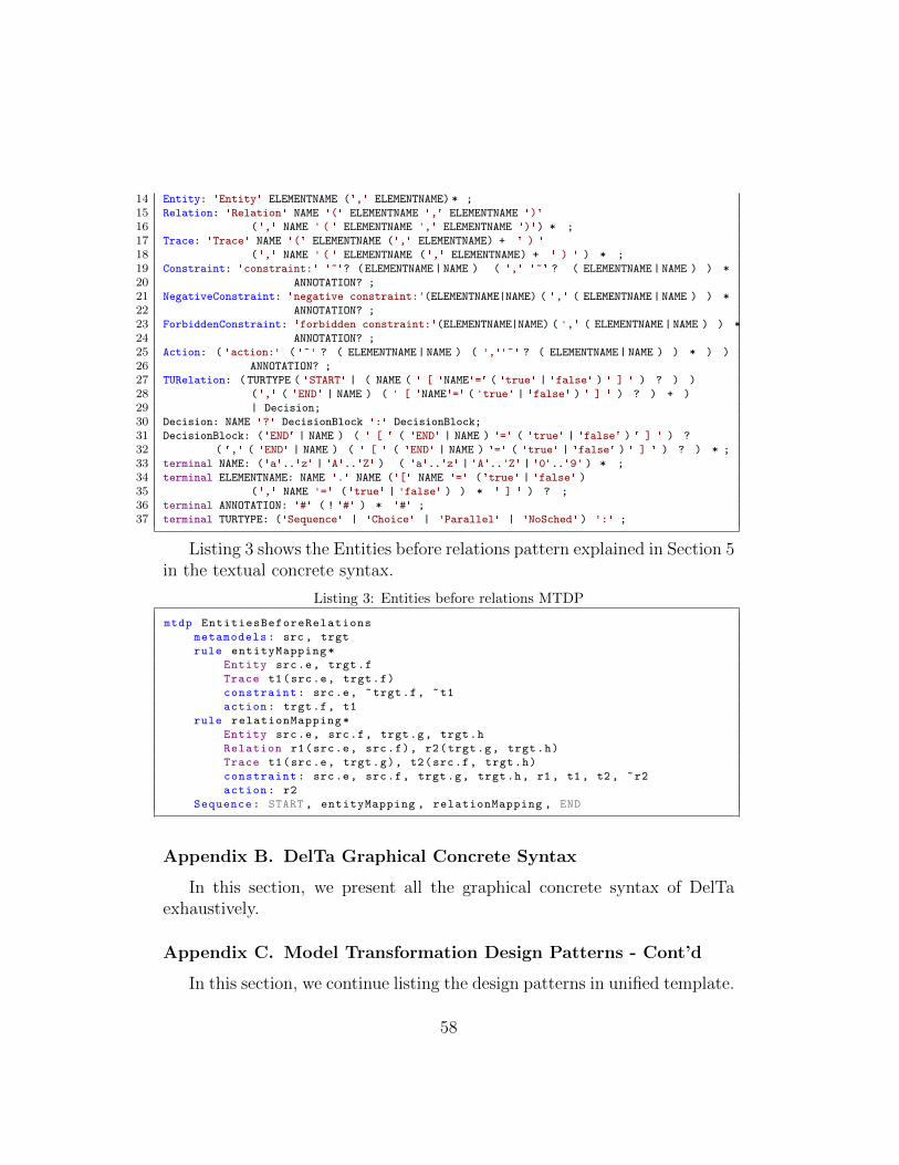
14 Entity: 'Entity' ELEMENTNAME (',' ELEMENTNAME) * ;
15 Relation: 'Relation' NAME '(' ELEMENTNAME ',' ELEMENTNAME ')'
16 (',' NAME ' ( ' ELEMENTNAME ',' ELEMENTNAME ')') * ;
17 Trace: 'Trace' NAME '(' ELEMENTNAME (',' ELEMENTNAME) + ' ) '
18 (',' NAME ' ( ' ELEMENTNAME (',' ELEMENTNAME) + ' ) ' ) * ;
19 Constraint: 'constraint:' '~'? (ELEMENTNAME|NAME ) ( ',' '~' ? ( ELEMENTNAME|NAME ) ) *
20 ANNOTATION? ;
21 NegativeConstraint: 'negative constraint:'(ELEMENTNAME|NAME) ( ',' ( ELEMENTNAME|NAME ) ) *
22 ANNOTATION? ;
23 ForbiddenConstraint: 'forbidden constraint:'(ELEMENTNAME|NAME) ( ',' ( ELEMENTNAME|NAME ) ) *
24 ANNOTATION? ;
25 Action: ( 'action:' ( '~' ? ( ELEMENTNAME|NAME ) ( ',''~' ? ( ELEMENTNAME| NAME ) ) * ) )
26 ANNOTATION? ;
27 TURelation: (TURTYPE ( 'START' | ( NAME ( ' [ 'NAME'=' ( 'true' | 'false' ) ' ] ' ) ? ) )
28 (',' ( 'END' | NAME ) ( ' [ 'NAME'=' ( 'true' | 'false' ) ' ] ' ) ? ) + )
29 | Decision;
30 Decision: NAME '?' DecisionBlock ':' DecisionBlock;
31 DecisionBlock: ('END' | NAME ) ( ' [ ' ( 'END' | NAME ) '=' ( 'true' | 'false' ) ' ] ' ) ?
32 ( ',' ( 'END' | NAME ) ( ' [ ' ( 'END' | NAME ) '=' ( 'true' | 'false' ) ' ] ' ) ? ) * ;
33 terminal NAME: ('a'..'z' | 'A'..'Z' ) ( 'a'..'z' | 'A'..'Z' | '0'..'9' ) * ;
34 terminal ELEMENTNAME: NAME '.' NAME ('[' NAME '=' ('true' | 'false' )
35 (',' NAME '=' ('true' | 'false' ) ) * ' ] ' ) ? ;
36 terminal ANNOTATION: '#' ( ! '#' ) * '#' ;
37 terminal TURTYPE: ('Sequence' | 'Choice' | 'Parallel' | 'NoSched' ) ':' ;
Listing 3 shows the Entities before relations pattern explained in Section 5in the textual concrete syntax.
Listing 3: Entities before relations MTDP
mtdp EntitiesBeforeRelations
metamodels: src , trgt
rule entityMapping*
Entity src.e, trgt.f
Trace t1(src.e, trgt.f)
constraint: src.e, ~trgt.f, ~t1
action: trgt.f, t1
rule relationMapping*
Entity src.e, src.f, trgt.g, trgt.h
Relation r1(src.e, src.f), r2(trgt.g, trgt.h)
Trace t1(src.e, trgt.g), t2(src.f, trgt.h)
constraint: src.e, src.f, trgt.g, trgt.h, r1, t1 , t2 , ~r2
action: r2
Sequence: START , entityMapping , relationMapping , END
Appendix B. DelTa Graphical Concrete Syntax
In this section, we present all the graphical concrete syntax of DelTaexhaustively.
Appendix C. Model Transformation Design Patterns - Cont’d
In this section, we continue listing the design patterns in unified template.
58
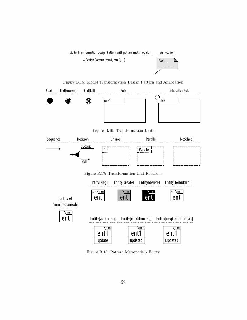
Model Transformation Design Pattern with pattern metamodels
A Design Pattern (mm1, mm2, ...)
Annotation
Note....
....................
Figure B.15: Model Transformation Design Pattern and Annotation
rule1 rule2
Start End[success] End[fail] Rule Exhaustive Rule
Figure B.16: Transformation Units
Sequence Decision Choice Parallel NoSched
fail
success1 Parallel
Figure B.17: Transformation Unit Relations
Entity of
'mm' metamodel
Entity[create] Entity[delete] Entity[forbidden]
mm
ent
mm
entmm
entmm
entx
mm
ent1update
Entity[actionTag]
mm
ent1updated
Entity[conditionTag]
mm
ent1!updated
Entity[negConditionTag]
Entity[Neg]
mm
entn0
Figure B.18: Pattern Metamodel - Entity
59

Relation[Neg]Relation
n0
Relation[Create] Relation[Delete] Relation[Forbidden]
X
Trace[Neg]Trace
n0
Trace[Create] Trace[Delete] Trace[Forbidden]
X
Figure B.19: Pattern Metamodel - Relation and Trace
Appendix C.1. Visitor
This pattern falls under the “rule modularization” category.
� Summary: This pattern traverses all the nodes in a tree and processeseach entity individually [27].
� Application Conditions: The pattern can be applied to problemsthat consist of (or can be mapped to) a tree structure where all thenodes need to be processed individually.
� Solution: The structure of the pattern is depicted in Fig. C.20. Thepattern starts by marking an entity with an action tag in the markIni-tEntity rule. Then, in the visitEntity rule, the marked entity is taggedas processed, if it has not been processed yet. The markNextEntityrule marks the immediate child of the last processed entities as markedand returns back to the visitEntity rule. It accomplishes this with adecision relation and fail/success branches. The condition and actiontags appear in the low compartment of the entity.
� Benefits: The pattern allows for the individual processing of nodesin a specific order, rather than bulk modification operations of modeltransformations. Note that a context can be provided when processingan entity of the metamodel. The pattern also allows for different modeltraversal strategies.
� Disadvantages: A loop helps to traverse the tree structure, thereforethe parallelization of the rules is more difficult.
60
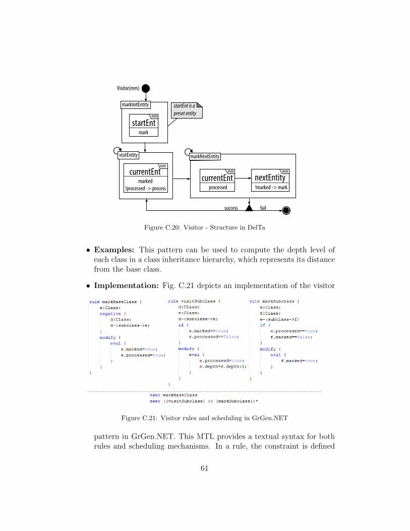
startEnt is a
preset entity
failsuccess
markInitEntity
mm
startEntmark
mm
currentEntmarked
!processed -> process
mm
currentEntprocessed
mm
nextEntity!marked -> mark
Visitor(mm)
visitEntity markNextEntity
Figure C.20: Visitor - Structure in DelTa
� Examples: This pattern can be used to compute the depth level ofeach class in a class inheritance hierarchy, which represents its distancefrom the base class.
� Implementation: Fig. C.21 depicts an implementation of the visitor
Figure C.21: Visitor rules and scheduling in GrGen.NET
pattern in GrGen.NET. This MTL provides a textual syntax for bothrules and scheduling mechanisms. In a rule, the constraint is defined
61

by declaring the elements of the pattern and conditions on attributesare checked with an if statement. Actions are written in a modify orreplace statement for new node creation and eval statements are used forattribute manipulation. The markBaseClass rule selects a class with nosuperclass as the initial element to visit. Because this class already hasa depth level of 0, we flag it as processed to prevent the visitSubclass rulefrom increasing its depth. This is a clear example of the minimality ofa MTDP rule, where the implementation extends the rule according tothe application. The visitSubclass rule processes the marked elements.Here, processing consists of increasing the depth of the subclass by onemore than the depth of the superclass. The markSubclass rule marks sub-classes of already marked classes. The scheduling of these GrGen.NETrules is depicted in the bottom of Fig. C.21. As stated in the designpattern structure, markBaseClass is executed only once. visitSubclass andmarkSubclass are sequenced with the ;> symbol. The ∗ indicates to ex-ecute this sequence as long as markSubclass rule succeeds. At the end,all classes should have their correct depth level set and all marked asprocessed. Note that in this implementation, visitSubclass will not beapplied in the first iteration of the loop.
� Related patterns: The pattern is related to phased construction andrecursive descent patterns [12], when the structure resembles a tree.
� Variations: The context that is needed to process elements can change.Also, visitEntity and markNextEntity rules can be NoSched rules withone rule per type inside to parallelize them. Finally, the ordering of thevisit can be adapted to be depth-first, breadth-first, or custom order.
Appendix C.2. Transitive Closure
This pattern falls under the “rule modularization” category.
� Summary: Transitive closure is a pattern typically used for analyzingreachability related problems with an in-place transformation. It wasproposed as a pattern in [11] and in [33]. It generates the intermediatepaths between nodes that are not necessarily directly connected viatraceability links.
� Application Conditions: The transitive closure pattern is applica-ble when the metamodels in the domain have a structure that can beconsidered as a directed tree.
62

� Solution: The solution is depicted in Fig. C.22. The pattern operateson a single metamodel. First, the immediateRelation rule creates a traceelement between entities connected with a relation. It is applied re-cursively to cover all relations. Then, the recursiveRelation rule createstrace elements between the node indirectly connected. That is, if enti-ties child and parent are connected with a trace, then child and ancestor
will also connected with a trace. It is also applied recursively to coverall nodes exhaustively.
mm
childmm
parent
mm
childmm
parent
mm
ancestor
Transitive Closure(mm)
n0n0
immediateRelation
recursiveRelation
Figure C.22: Transitive Closure - Structure in DelTa
� Benefits: Since all the trace elements are created from each elementto all its ancestors, queries relying on this information lookups areoptimal. The resulting model is still valid conforming to its metamodelbecause trace links are created outside the scope of the metamodel.There are no side-effects and both rules are parallelizable.
� Disadvantages: The application of the pattern creates many traceelements for single elements which can create a memory overflow whenthe model is too large. We need a rule for each type of relation, alsofor each combination of entity types, but that can be leveraged if usingabstract types defined in the metamodel (i.e., super types can be usedinstead of the subtypes).
� Examples: The transitive closure pattern can be used to find thelowest common ancestor between two nodes in a directed tree, such asfinding all superclasses of a class in UML class diagram.
� Implementation: We have implemented the transitive closure in AGG.Fig. C.23 depicts the corresponding rules. AGG rules consist of thetraditional LHS, RHS, and NACs. The LHS and NACs represent theconstraint of the MTDP rule and the RHS encodes the action. The
63
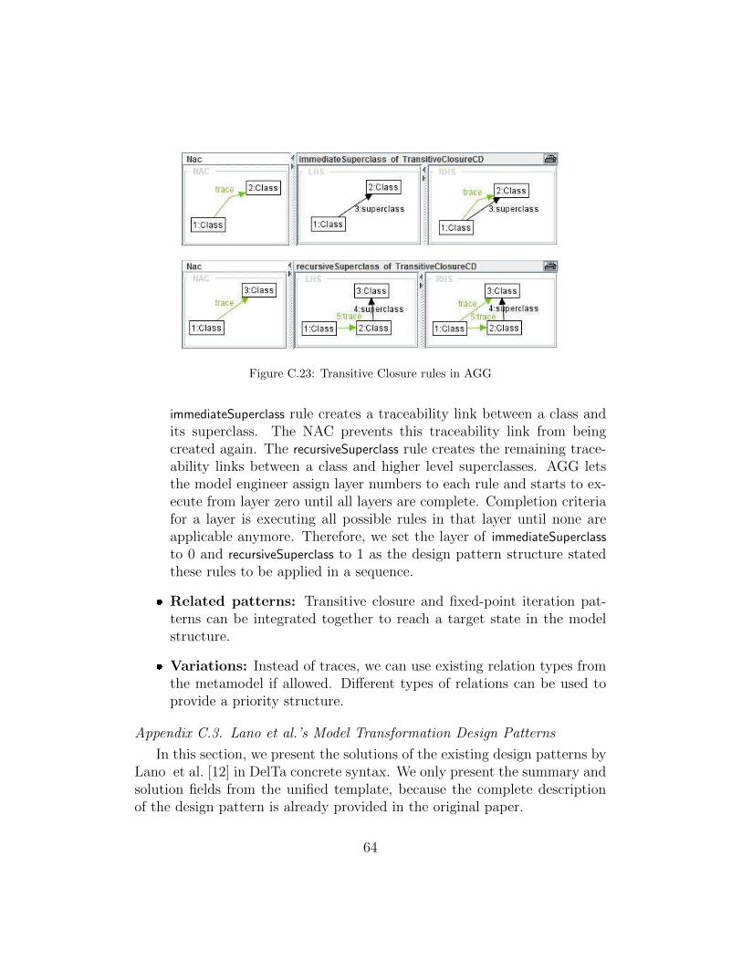
Figure C.23: Transitive Closure rules in AGG
immediateSuperclass rule creates a traceability link between a class andits superclass. The NAC prevents this traceability link from beingcreated again. The recursiveSuperclass rule creates the remaining trace-ability links between a class and higher level superclasses. AGG letsthe model engineer assign layer numbers to each rule and starts to ex-ecute from layer zero until all layers are complete. Completion criteriafor a layer is executing all possible rules in that layer until none areapplicable anymore. Therefore, we set the layer of immediateSuperclass
to 0 and recursiveSuperclass to 1 as the design pattern structure statedthese rules to be applied in a sequence.
� Related patterns: Transitive closure and fixed-point iteration pat-terns can be integrated together to reach a target state in the modelstructure.
� Variations: Instead of traces, we can use existing relation types fromthe metamodel if allowed. Different types of relations can be used toprovide a priority structure.
Appendix C.3. Lano et al.’s Model Transformation Design Patterns
In this section, we present the solutions of the existing design patterns byLano et al. [12] in DelTa concrete syntax. We only present the summary andsolution fields from the unified template, because the complete descriptionof the design pattern is already provided in the original paper.
64
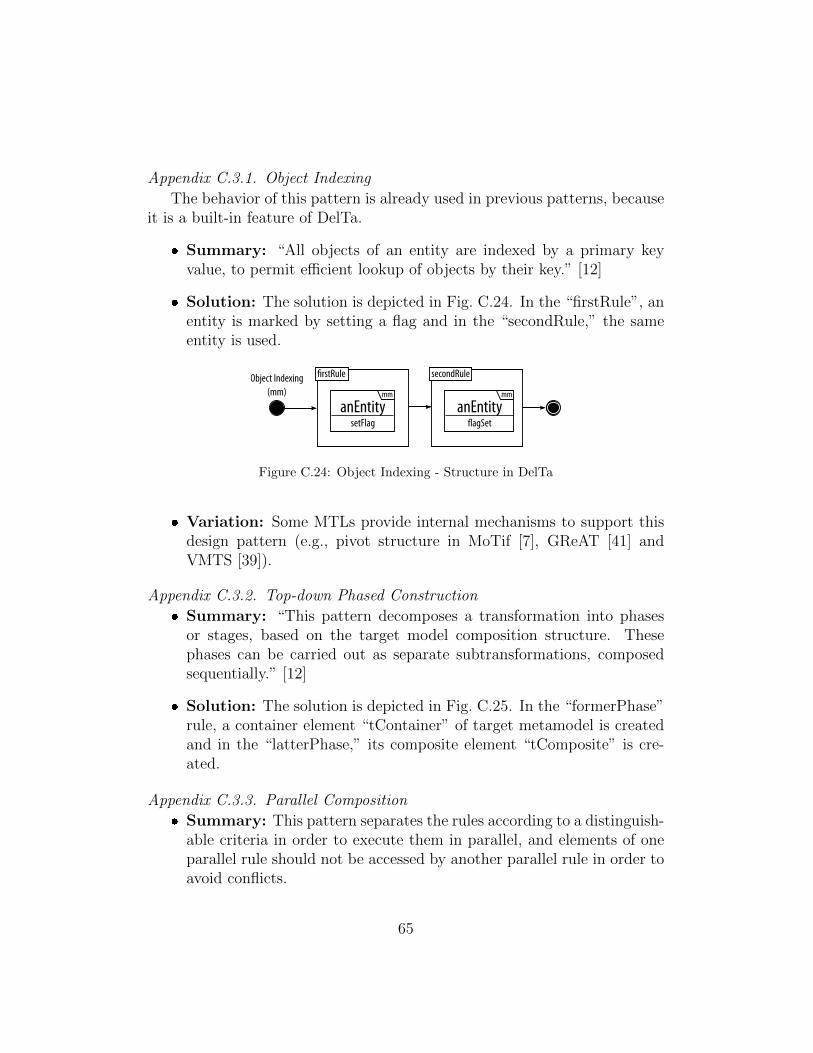
Appendix C.3.1. Object Indexing
The behavior of this pattern is already used in previous patterns, becauseit is a built-in feature of DelTa.
� Summary: “All objects of an entity are indexed by a primary keyvalue, to permit efficient lookup of objects by their key.” [12]
� Solution: The solution is depicted in Fig. C.24. In the “firstRule”, anentity is marked by setting a flag and in the “secondRule,” the sameentity is used.
Object Indexing
(mm)
�rstRule
mm
anEntitysetFlag
secondRule
mm
anEntity�agSet
Figure C.24: Object Indexing - Structure in DelTa
� Variation: Some MTLs provide internal mechanisms to support thisdesign pattern (e.g., pivot structure in MoTif [7], GReAT [41] andVMTS [39]).
Appendix C.3.2. Top-down Phased Construction
� Summary: “This pattern decomposes a transformation into phasesor stages, based on the target model composition structure. Thesephases can be carried out as separate subtransformations, composedsequentially.” [12]
� Solution: The solution is depicted in Fig. C.25. In the “formerPhase”rule, a container element “tContainer” of target metamodel is createdand in the “latterPhase,” its composite element “tComposite” is cre-ated.
Appendix C.3.3. Parallel Composition
� Summary: This pattern separates the rules according to a distinguish-able criteria in order to execute them in parallel, and elements of oneparallel rule should not be accessed by another parallel rule in order toavoid conflicts.
65

src
sContainertrgt
tContainern0
n0
Top-down
Phased Construction
(src, trgt)
formerPhase
src
sComposite
src
sContainertrgt
tContainer
latterPhase
src
sCompositetrgt
tCompositen0
n0
n0
Figure C.25: Top-down Phased Construction - Structure in DelTa
� Solution: The solution is depicted in Fig. C.26. The “parallel1” and“parallel2” rules are to be executed in parallel and if “ent1” is updatedin the first parallel rule, then it should not exist in “parallel2” rule,therefore it is marked with an “x” on top left in the latter rule. Thesame situation is true for “ent2” in the “parallel2” rule.
Parallel Composition
(mm)
parallel1
mm
ent1update
mm
ent2
parallel2
mm
ent1
mm
ent2update
x
x
Parallel
Figure C.26: Parallel Composition - Structure in DelTa
Appendix C.3.4. Unique Instantiation
� Summary: This pattern makes sure the created elements in a ruleare unique and eliminates redundant creation of the same element byreuse.
� Solution: The solution is depicted in Fig. C.27. If “someEnt” elementis created in a rule to be chosen from a group of rules, which are putinside a “NoSched” TUR, then it should not be created in another rule,which violates “someEnt”s being unique.
Appendix C.3.5. Entity Splitting
� Summary: This pattern separates the rules into pieces so that allcreations must be done in its own rule when different types of targetelements are created by the same source element.
66

Unique Instantiation
(mm)
create1
mm
someEntunique
create2
mm
someEntx
Figure C.27: Unique Instantiation - Structure in DelTa
� Solution: The solution is depicted in Fig. C.28. In the solution, “sEnt”is creating two different target elements, “tEnt1” and “tEnt2.” There-fore, they should be created in different rules grouped in a “NoSched”TUR.
src
sEnttrgt
tEnt1n0
n0
Entity Splitting
(src, trgt)aSplit
src
sEnttrgt
tEnt2n0
n0
anotherSplit
Figure C.28: Entity Splitting - Structure in DelTa
Appendix C.3.6. Entity Merging
� Summary: This pattern separates the rules if the same target elementis updated by different source elements. Each update by a differentsource element should occur within its separate rule.
� Solution: The solution is depicted in Fig. C.29. In the solution, after“tEnt” is created in the first rule, then it is updated by several differ-ent elements in the second NoSched TUR. Each update coming fromdifferent source elements should be in different rules.
Appendix C.3.7. Construction & Cleanup
� Summary: “This pattern structures a transformation by separatingrules which construct model elements from those which delete ele-
67
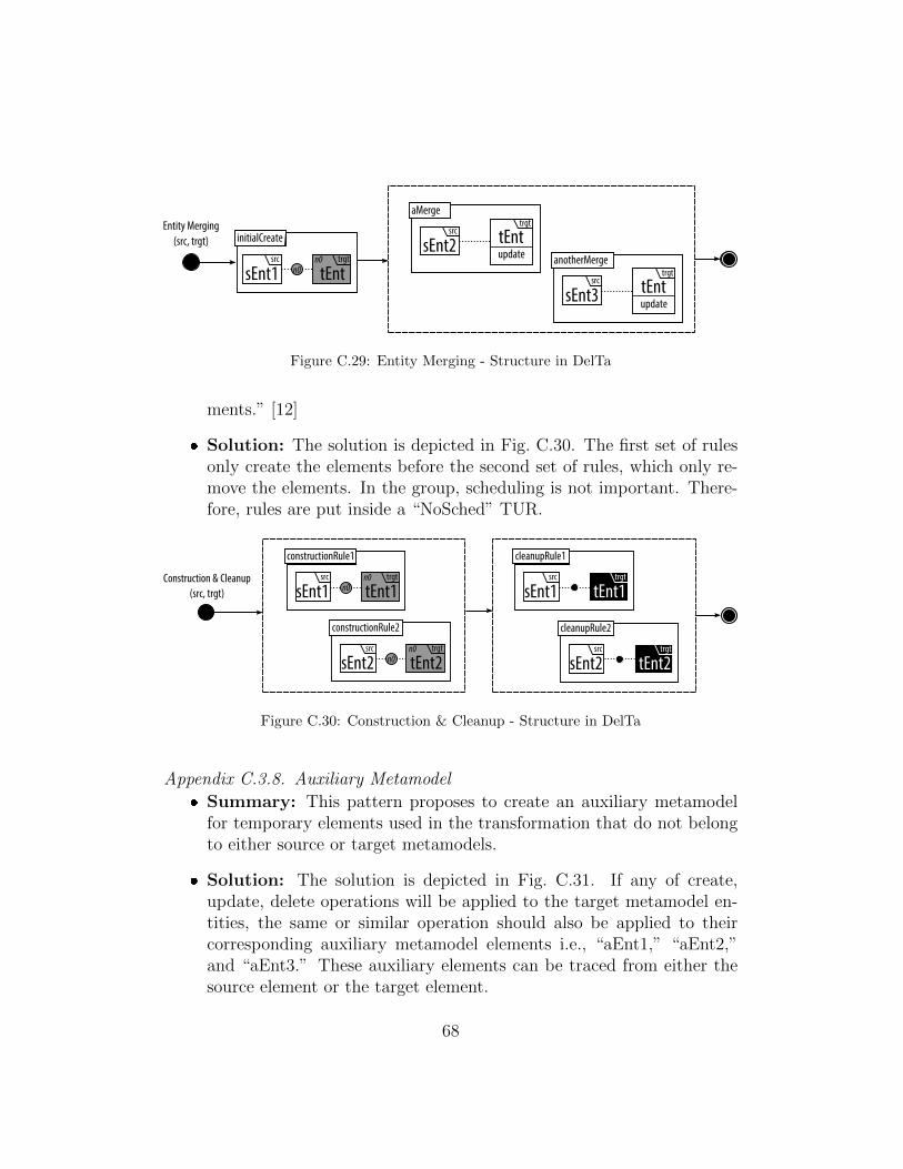
Entity Merging
(src, trgt)
src
sEnt1trgt
tEntn0
n0
initialCreate
trgt
tEntupdate
src
sEnt2
aMerge
trgt
tEntupdate
src
sEnt3
anotherMerge
Figure C.29: Entity Merging - Structure in DelTa
ments.” [12]
� Solution: The solution is depicted in Fig. C.30. The first set of rulesonly create the elements before the second set of rules, which only re-move the elements. In the group, scheduling is not important. There-fore, rules are put inside a “NoSched” TUR.
src
sEnt1trgt
tEnt1n0
n0Construction & Cleanup
(src, trgt)
constructionRule1
src
sEnt2trgt
tEnt2n0
n0
constructionRule2
src
sEnt1trgt
tEnt1
cleanupRule1
src
sEnt2trgt
tEnt2
cleanupRule2
Figure C.30: Construction & Cleanup - Structure in DelTa
Appendix C.3.8. Auxiliary Metamodel
� Summary: This pattern proposes to create an auxiliary metamodelfor temporary elements used in the transformation that do not belongto either source or target metamodels.
� Solution: The solution is depicted in Fig. C.31. If any of create,update, delete operations will be applied to the target metamodel en-tities, the same or similar operation should also be applied to theircorresponding auxiliary metamodel elements i.e., “aEnt1,” “aEnt2,”and “aEnt3.” These auxiliary elements can be traced from either thesource element or the target element.
68
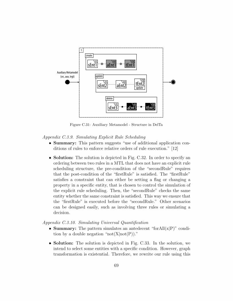
Auxiliary Metamodel
(src, aux, trgt)
src
sEnt1trgt
tEnt1
create
aux
aEnt1
1
src
sEnt2
trgt
tEnt2
update
aux
aEnt2update
src
sEnt3trgt
tEnt3
delete
aux
aEnt3
Figure C.31: Auxiliary Metamodel - Structure in DelTa
Appendix C.3.9. Simulating Explicit Rule Scheduling
� Summary: This pattern suggests “use of additional application con-ditions of rules to enforce relative orders of rule execution.” [12]
� Solution: The solution is depicted in Fig. C.32. In order to specify anordering between two rules in a MTL that does not have an explicit rulescheduling structure, the pre-condition of the “secondRule” requiresthat the post-condition of the “firstRule” is satisfied. The “firstRule”satisfies a constraint that can either be setting a flag or changing aproperty in a specific entity, that is chosen to control the simulation ofthe explicit rule scheduling. Then, the “secondRule” checks the sameentity whether the same constraint is satisfied. This way we ensure thatthe “firstRule” is executed before the “secondRule.” Other scenarioscan be designed easily, such as involving three rules or simulating adecision.
Appendix C.3.10. Simulating Universal Quantification
� Summary: The pattern simulates an antedecent “forAll(x|P)” condi-tion by a double negation “not(X|not(P)).”
� Solution: The solution is depicted in Fig. C.33. In the solution, weintend to select some entities with a specific condition. However, graphtransformation is existential. Therefore, we rewrite our rule using this
69

Simulating Explicit
Rule Scheduling
(mm)
firstRule
mm
schedEntsatisfyConstraint secondRule
mm
schedEntconstraintSatisfied
Figure C.32: Simulating Explicit Rule Scheduling - Structure in DelTa
pattern. Finally, the “select” rule tries to select entities those do notsatisfy the condition and returns true if it can not find such a rule andvice versa.
Simulating Universal
Quantification (mm)
select
mm
anEntity!condition
fail
success
Figure C.33: Simulating Universal Quantification - Structure in DelTa
� Implementation: In the “terminatingCondition” rules of Fig. 6, weshow how this pattern is applied. In these rules, we want to select afiring “transition,” which means finding a “transition” with all incom-ing edges have token weights either equal to or less than tokens of theircorresponding “places.” We rewrite the rules using this pattern andtry to select a firing “transition,” if and only if that “transition” doesnot have negative condition of a firing “transition,” which is havingless token weight in the incoming edge than tokens of its corresponding“place.”
70