Embed Size (px)
Citation preview
DESIGN OPTIMIZATION OF HEAT TREATMENT SUPPORT FRAMES FOR
ALUMINUM ALLOY STRUCTURAL CAST PARTS USING VIRTUAL
EXPERIMENTATION
Heinz-Jürgen Gaspers1, Jesper Thorborg1
1 MAGMA Gießereitechnologie GmbH, Aachen, Germany
E-Mail: [email protected]
ABSTRACT
Heat Treatment is an often applied process to realize improved mechanical properties in
structural aluminium alloy cast parts, especially for applications in the automotive industry. In
many cases a T6/T7 heat treatment, which includes solution treatment, quenching and aging,
is the preferred option. For large, thin-walled structural die cast parts, the support during heat
treatment has a distinct influence on the deformation during the heat treatment process. The
deformation is mainly formed during the solution treatment step, where the part is heated to
above 460 °C for several hours for metallurgical reasons. The deformation is caused by
gravity forces which lead to creep in the material. As the parts usually only have a few
supporting contact areas, the final part distortion can be very sensitive to the design and lay-
out of the support frame. In addition distortions developing during the casting process as well
as during all heat treatment process stages must be considered to achieve that the final part
meets the dimensional specifications. Up to now only the experience of the expert as well as
extensive experimentation based on trial and error are the state-of-the art approaches to find
an “optimized” frame design for any new part. This may be time consuming and costly.
The work shows how heat treatment support frames can be optimized by virtual
experimentation using an integrated simulation approach. A unified creep material model is
applied to model the distortion of an industrial thin-walled aluminium structural die cast part.
The changing part deformation during the entire casting and heat treatment process as well as
the effects of different supporting frame concepts on the distortion will be discussed. The
predicted part deformation is compared for different supporting frame designs and is
quantitatively assessed using a virtual 6-point (Reference Point System) measurement device.
KEYWORDS
Stress simulation, minimizing distortions, gravity, aluminium, structural part, solution
treatment, precipitation hardening, creep, virtual experimentation, optimization
INTRODUCTION
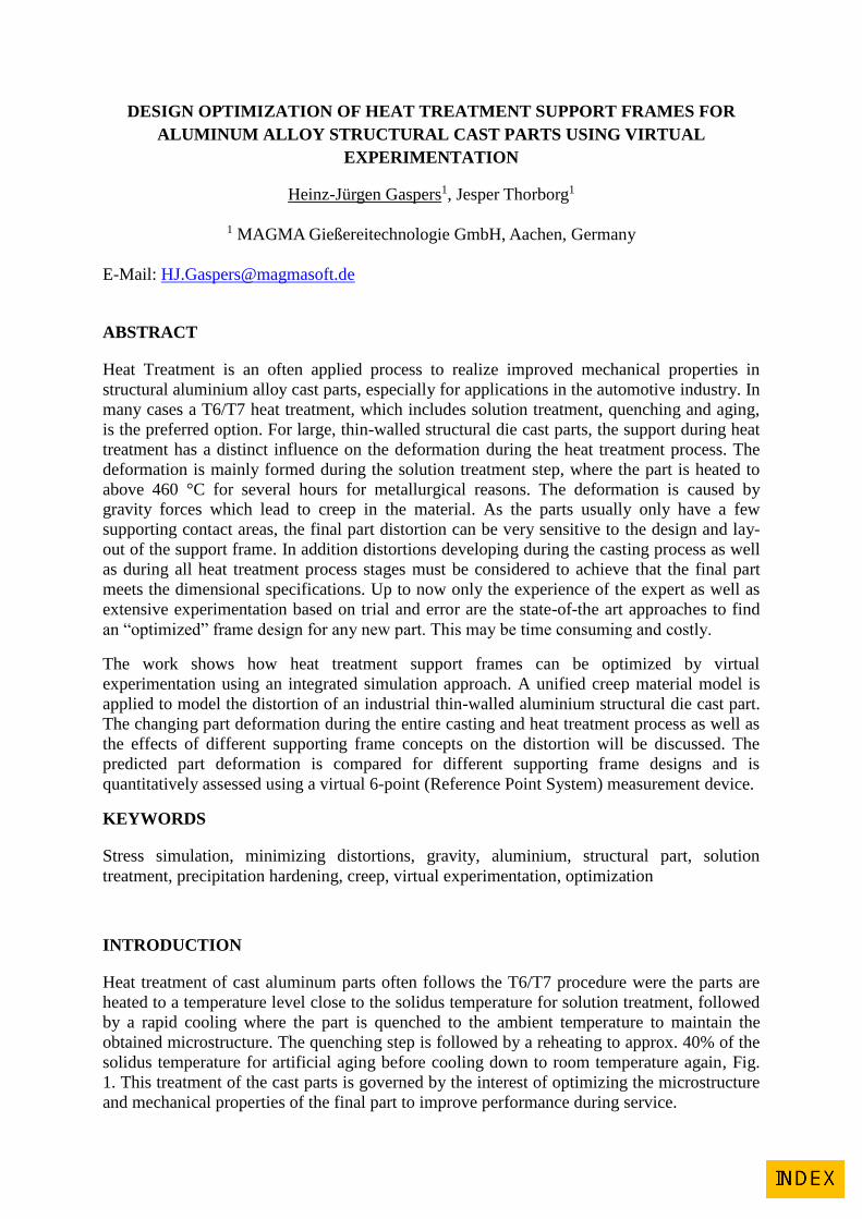
Heat treatment of cast aluminum parts often follows the T6/T7 procedure were the parts are
heated to a temperature level close to the solidus temperature for solution treatment, followed
by a rapid cooling where the part is quenched to the ambient temperature to maintain the
obtained microstructure. The quenching step is followed by a reheating to approx. 40% of the
solidus temperature for artificial aging before cooling down to room temperature again, Fig.
1. This treatment of the cast parts is governed by the interest of optimizing the microstructure
and mechanical properties of the final part to improve performance during service.
The most widely used aluminum casting alloys are based on different contents of Si, Cu and
Mg. For the hypoeutectic alloys, the microstructure consists of a primary -Al phase and Al-
Si eutectic. The additional components Mg and Cu are either contained in the -Al in solid
solution or precipitated as intermetallic phases e.g. Mg2Si or Al2Cu. The content of Mg and
Cu in solid solution is temperature dependent according to the phase diagram, [1]. This
temperature dependency is exploited during solution treatment to form a super-saturated
solution of Mg and Cu, which is maintained during quenching to allow a controlled
precipitation of intermetallic phases during artificial aging.
Fig. 1: Left: Process view showing the thermal history of the casting and heat treatment
processes. Right: The phase diagram indicating the path for generating the super-saturated
solid solution.
However, the heat treatment process can also have a major influence on the development of
distortions and stresses in the part due to the elevated temperature level during solution
treatment and possible thermal gradients during the quenching step. For bulk parts, such as
cylinder heads etc., the deformation during the solution treatment step can be more or less
neglected, while the gravity forces on thin-walled structural parts can have a significant
influence on the overall deformation during heat treatment.
For thin-walled structural parts a moderate air quenching is sufficient to obtain a satisfying
microstructure inside the material. Since this type of cooling leads to small thermal gradients,
structural parts do typically not build up large plastic deformation during the quenching step.
At higher temperature levels however, the strength of the aluminum part decreases during the
solution treatment step, allowing gravity forces to deform the parts due to creep, [2].
Depending on the handling and supports during the high temperature treatment thin-walled
structural parts can be distorted considerably, [3].
During the final artificial aging step, the temperature level is only increased to allow the
precipitation hardening to take place. This temperature level can lead to moderate stress
relaxation due to creep but typically not to additional deformations. Thermo-mechanical
modeling of the casting and heat treatment process is a challenge even without considering
the evolution of the material data. The main concern is to model the response of the material
at different temperature levels, on different time scales and sometimes with different strain
rates, which is governed by different deformation mechanisms. To have a reasonable
compromise between the stability in the results when doing calculations in different process
steps and agreement between simulations and performed creep and tensile tests, a unified
creep formulation is used as the fundamental constitutive law, [4], in this work. The model is
based on Norton’s power law and includes by that, strain rate sensitivity and the possibility to
describe creep at elevated temperature, [5] and [6].

1. OPTIMIZING THE SUPPORT FRAME DURING SOLUTION TREATMENT
The example presented in this paper is a thin-walled structural part, in the following called
“connecting part LTR”, of the Audi TT vehicle. Fig. 2 shows the part and its position in the
Audi TT space frame. The part is connecting the back seat area and the side wall in the main
frame. Detailed simulations, experiments and measurements of deformations and changing
material properties during and after heat treatment of this part were done in a research project
named “ProGRess”, [7], with partners MAGMA GmbH, Trimet and Audi AG. The main
objectives of “ProGRess” were investigations concerning the possibilities to save energy
during the casting processes, and the heat treatment process, while at the same time to
maintain quality and mechanical properties. Therefore variations of temperatures and holding
times of the solution treatment step were performed. Following the experiments of the project
additional virtual DOE experiments have been done by MAGMA and are presented in this
paper.
Fig. 2: Structural part of Audi TT
Fig. 3, left shows the performed experiments of solution treatment with temperatures and
times based on the “reference” solution treatment with 485 °C for 2 hours. Fig. 3, right shows
the measured mechanical properties and energies used for the different variants of solution
treatment.
Version
Temperature
[ºC]
Time
[min]
1 -20 -20
2 -20 +/-0
3 -20 +20
4 +50 -80
5 +50 -60
6 +50 -40
7 +50 -20
8 +50 +/-0
9 +/-0 -95
10 +/-0 -80
11 +/-0 -65
12 Reference
Fig. 3: Left: Solution treatment experiments with different temperatures and holding times.
Right: Mechanical properties and energy usage for the different variants.
Connecting Part LTR
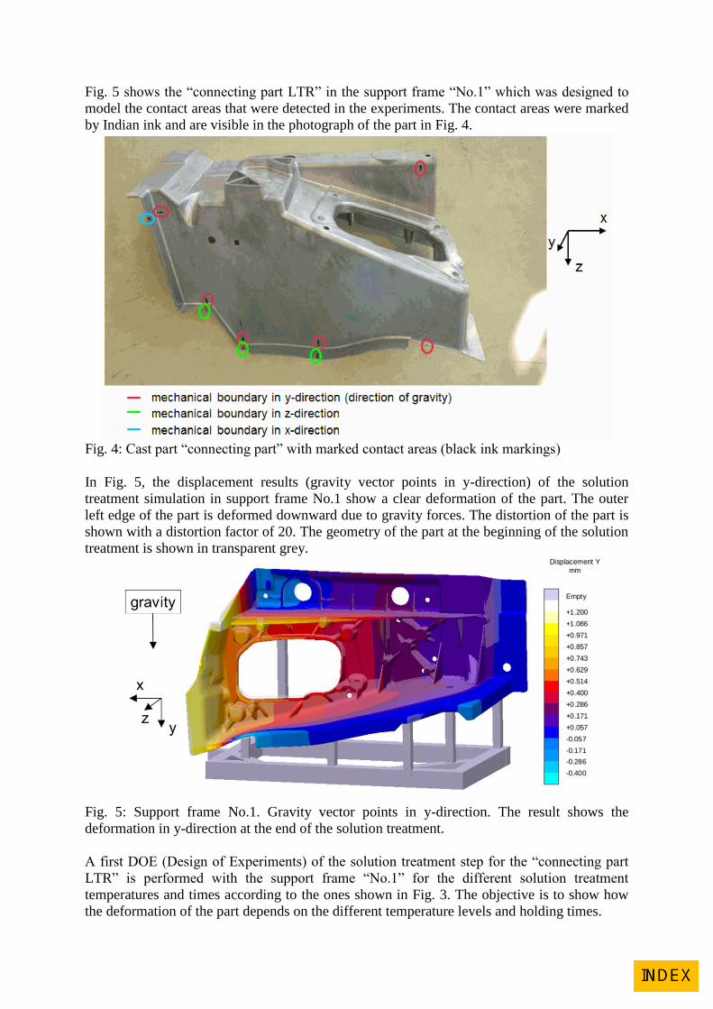
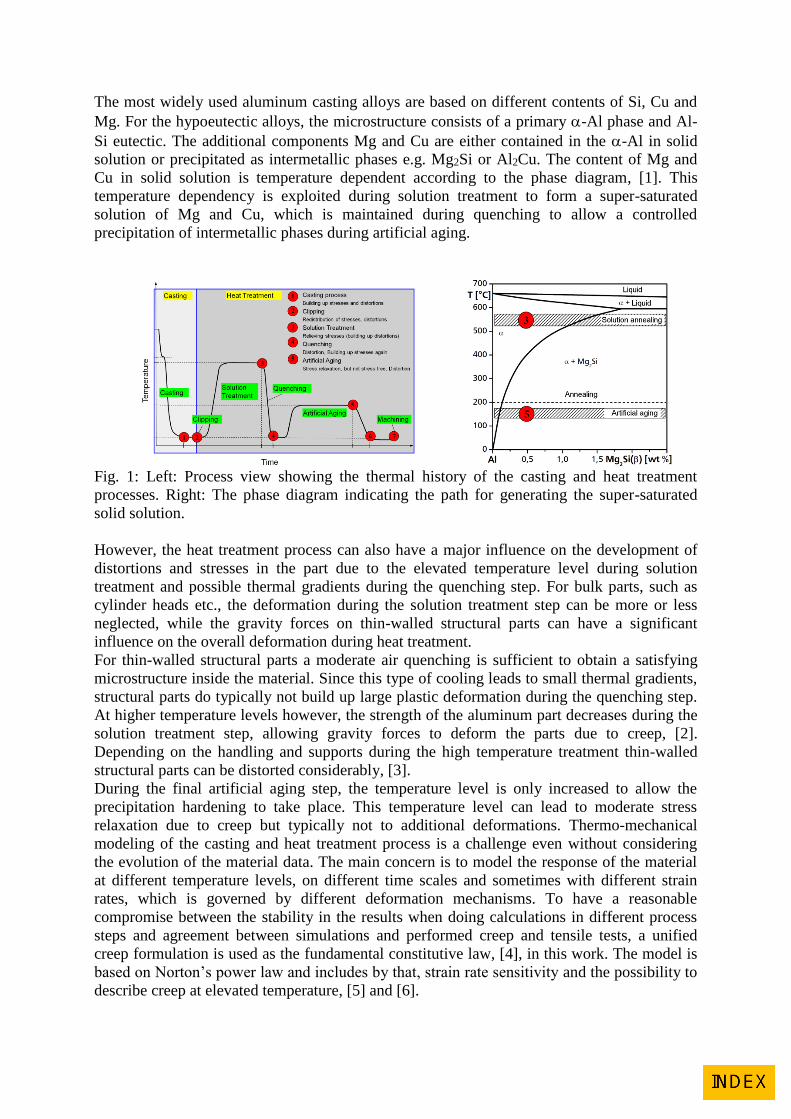
Fig. 5 shows the “connecting part LTR” in the support frame “No.1” which was designed to
model the contact areas that were detected in the experiments. The contact areas were marked
by Indian ink and are visible in the photograph of the part in Fig. 4.
Fig. 4: Cast part “connecting part” with marked contact areas (black ink markings)
In Fig. 5, the displacement results (gravity vector points in y-direction) of the solution
treatment simulation in support frame No.1 show a clear deformation of the part. The outer
left edge of the part is deformed downward due to gravity forces. The distortion of the part is
shown with a distortion factor of 20. The geometry of the part at the beginning of the solution
treatment is shown in transparent grey.
Fig. 5: Support frame No.1. Gravity vector points in y-direction. The result shows the
deformation in y-direction at the end of the solution treatment.
A first DOE (Design of Experiments) of the solution treatment step for the “connecting part
LTR” is performed with the support frame “No.1” for the different solution treatment
temperatures and times according to the ones shown in Fig. 3. The objective is to show how
the deformation of the part depends on the different temperature levels and holding times.
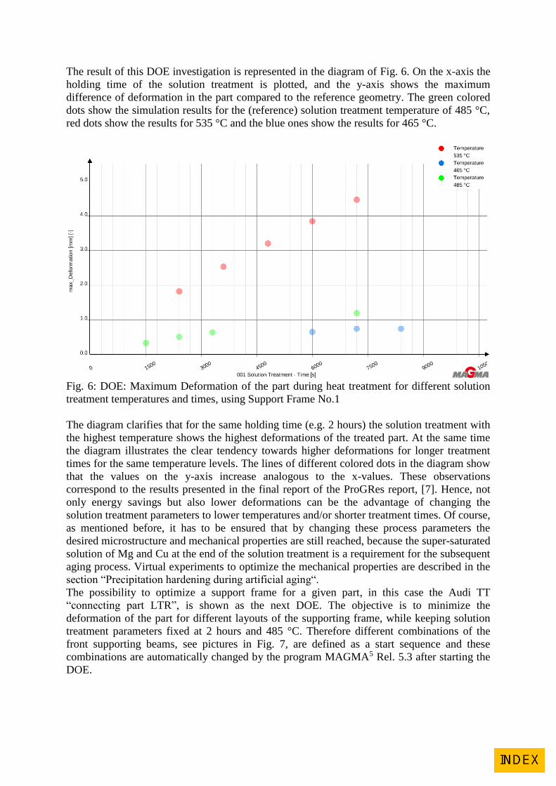
The result of this DOE investigation is represented in the diagram of Fig. 6. On the x-axis the
holding time of the solution treatment is plotted, and the y-axis shows the maximum
difference of deformation in the part compared to the reference geometry. The green colored
dots show the simulation results for the (reference) solution treatment temperature of 485 °C,
red dots show the results for 535 °C and the blue ones show the results for 465 °C.
Fig. 6: DOE: Maximum Deformation of the part during heat treatment for different solution
treatment temperatures and times, using Support Frame No.1
The diagram clarifies that for the same holding time (e.g. 2 hours) the solution treatment with
the highest temperature shows the highest deformations of the treated part. At the same time
the diagram illustrates the clear tendency towards higher deformations for longer treatment
times for the same temperature levels. The lines of different colored dots in the diagram show
that the values on the y-axis increase analogous to the x-values. These observations
correspond to the results presented in the final report of the ProGRes report, [7]. Hence, not
only energy savings but also lower deformations can be the advantage of changing the
solution treatment parameters to lower temperatures and/or shorter treatment times. Of course,
as mentioned before, it has to be ensured that by changing these process parameters the
desired microstructure and mechanical properties are still reached, because the super-saturated
solution of Mg and Cu at the end of the solution treatment is a requirement for the subsequent
aging process. Virtual experiments to optimize the mechanical properties are described in the
section “Precipitation hardening during artificial aging“.
The possibility to optimize a support frame for a given part, in this case the Audi TT
“connecting part LTR”, is shown as the next DOE. The objective is to minimize the
deformation of the part for different layouts of the supporting frame, while keeping solution
treatment parameters fixed at 2 hours and 485 °C. Therefore different combinations of the
front supporting beams, see pictures in Fig. 7, are defined as a start sequence and these
combinations are automatically changed by the program MAGMA5 Rel. 5.3 after starting the
DOE.
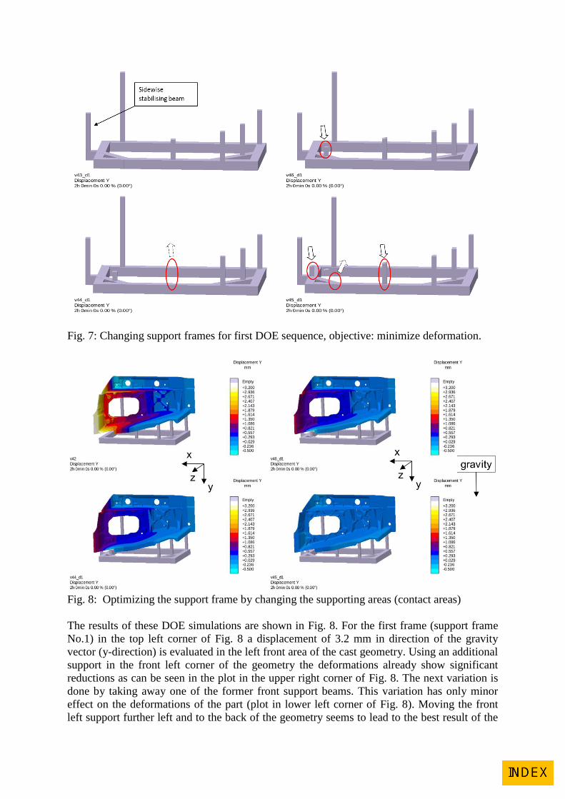
Fig. 7: Changing support frames for first DOE sequence, objective: minimize deformation.
Fig. 8: Optimizing the support frame by changing the supporting areas (contact areas)
The results of these DOE simulations are shown in Fig. 8. For the first frame (support frame
No.1) in the top left corner of Fig. 8 a displacement of 3.2 mm in direction of the gravity
vector (y-direction) is evaluated in the left front area of the cast geometry. Using an additional
support in the front left corner of the geometry the deformations already show significant
reductions as can be seen in the plot in the upper right corner of Fig. 8. The next variation is
done by taking away one of the former front support beams. This variation has only minor
effect on the deformations of the part (plot in lower left corner of Fig. 8). Moving the front
left support further left and to the back of the geometry seems to lead to the best result of the

performed variations with the lowest displacements in gravity (y-) direction, as the plot in the
lower right corner of Fig. 8 shows.
Up to this point the minimization of deformations has only been based on the evolution of
deformations during the heat treatment process. But in a real casting process the minor
percentage of all cast parts will have exactly the intended form of the reference (CAD)
geometry. In most cases the outcome of the casting process will differ more or less from this
targeted geometry. In these cases an additional deformation during heat treatment, if, of
course, going in the right direction, can even be helpful and bring the part back into
tolerances. And working with complex 3-D parts even experienced experts can only guess
which could be the best approach.
Fig. 9 shows the simulation results of the deformed “connection part LTR” after the casting
process. The geometry of the (pre-deformed) part after the casting simulation is already
positioned onto the support frame No.1 (supporting frame No.1 is shown in the upper right-
hand corner of Fig. 7) and again the solution treatment is simulated as described above. The
earlier simulations did not take into account deformations caused by the casting process and
were performed with the CAD geometry.
Fig. 9: Deformed part after casting simulation is positioned onto heat treatment support frame
No.1. Contours show deformation after casting.
Fig. 10: Deformations of the cast part (pre-deformed after casting) after solution treatment
when supported on frame No.1. Contours only show deformation due to heat treatment.
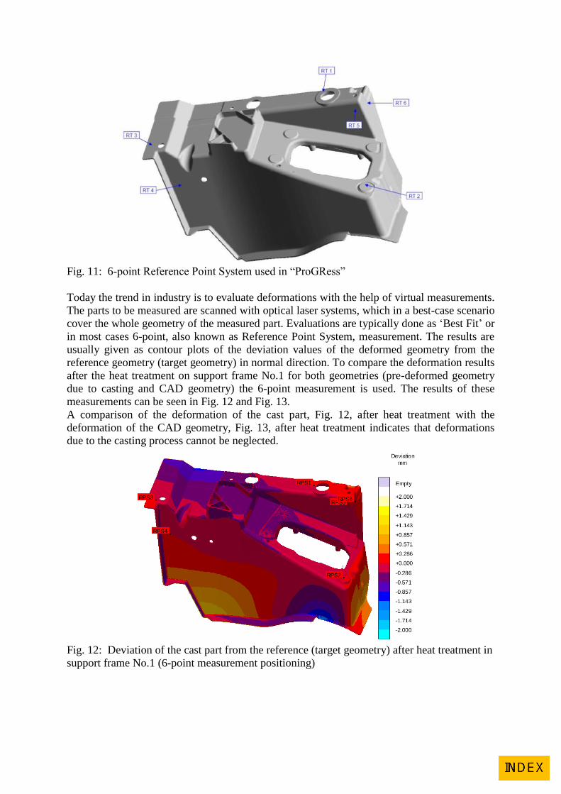
Fig. 11: 6-point Reference Point System used in “ProGRess”
Today the trend in industry is to evaluate deformations with the help of virtual measurements.
The parts to be measured are scanned with optical laser systems, which in a best-case scenario
cover the whole geometry of the measured part. Evaluations are typically done as ‘Best Fit’ or
in most cases 6-point, also known as Reference Point System, measurement. The results are
usually given as contour plots of the deviation values of the deformed geometry from the
reference geometry (target geometry) in normal direction. To compare the deformation results
after the heat treatment on support frame No.1 for both geometries (pre-deformed geometry
due to casting and CAD geometry) the 6-point measurement is used. The results of these
measurements can be seen in Fig. 12 and Fig. 13.
A comparison of the deformation of the cast part, Fig. 12, after heat treatment with the
deformation of the CAD geometry, Fig. 13, after heat treatment indicates that deformations
due to the casting process cannot be neglected.
Fig. 12: Deviation of the cast part from the reference (target geometry) after heat treatment in
support frame No.1 (6-point measurement positioning)
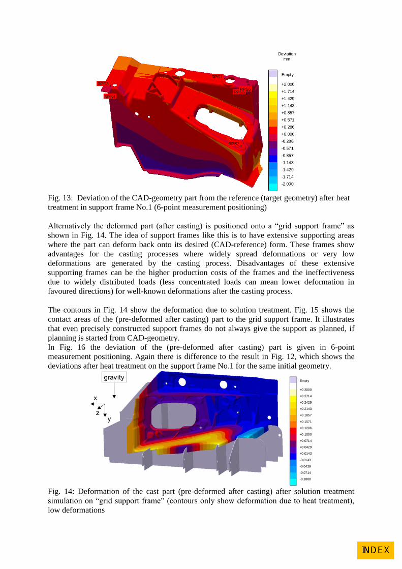
Fig. 13: Deviation of the CAD-geometry part from the reference (target geometry) after heat
treatment in support frame No.1 (6-point measurement positioning)
Alternatively the deformed part (after casting) is positioned onto a “grid support frame” as
shown in Fig. 14. The idea of support frames like this is to have extensive supporting areas
where the part can deform back onto its desired (CAD-reference) form. These frames show
advantages for the casting processes where widely spread deformations or very low
deformations are generated by the casting process. Disadvantages of these extensive
supporting frames can be the higher production costs of the frames and the ineffectiveness
due to widely distributed loads (less concentrated loads can mean lower deformation in
favoured directions) for well-known deformations after the casting process.
The contours in Fig. 14 show the deformation due to solution treatment. Fig. 15 shows the
contact areas of the (pre-deformed after casting) part to the grid support frame. It illustrates
that even precisely constructed support frames do not always give the support as planned, if
planning is started from CAD-geometry.
In Fig. 16 the deviation of the (pre-deformed after casting) part is given in 6-point
measurement positioning. Again there is difference to the result in Fig. 12, which shows the
deviations after heat treatment on the support frame No.1 for the same initial geometry.
Fig. 14: Deformation of the cast part (pre-deformed after casting) after solution treatment
simulation on “grid support frame” (contours only show deformation due to heat treatment),
low deformations
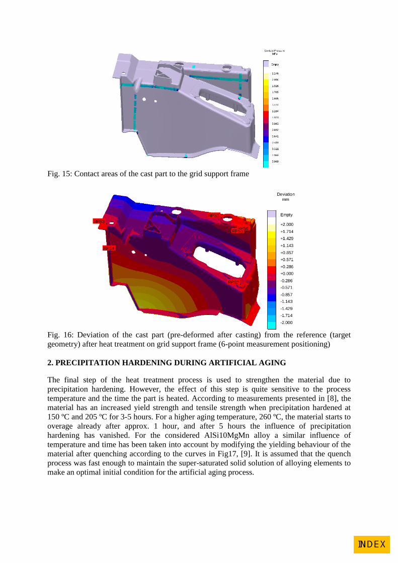
Fig. 15: Contact areas of the cast part to the grid support frame
Fig. 16: Deviation of the cast part (pre-deformed after casting) from the reference (target
geometry) after heat treatment on grid support frame (6-point measurement positioning)
2. PRECIPITATION HARDENING DURING ARTIFICIAL AGING
The final step of the heat treatment process is used to strengthen the material due to
precipitation hardening. However, the effect of this step is quite sensitive to the process
temperature and the time the part is heated. According to measurements presented in [8], the
material has an increased yield strength and tensile strength when precipitation hardened at
150 ºC and 205 ºC for 3-5 hours. For a higher aging temperature, 260 ºC, the material starts to
overage already after approx. 1 hour, and after 5 hours the influence of precipitation
hardening has vanished. For the considered AlSi10MgMn alloy a similar influence of
temperature and time has been taken into account by modifying the yielding behaviour of the
material after quenching according to the curves in Fig17, [9]. It is assumed that the quench
process was fast enough to maintain the super-saturated solid solution of alloying elements to
make an optimal initial condition for the artificial aging process.
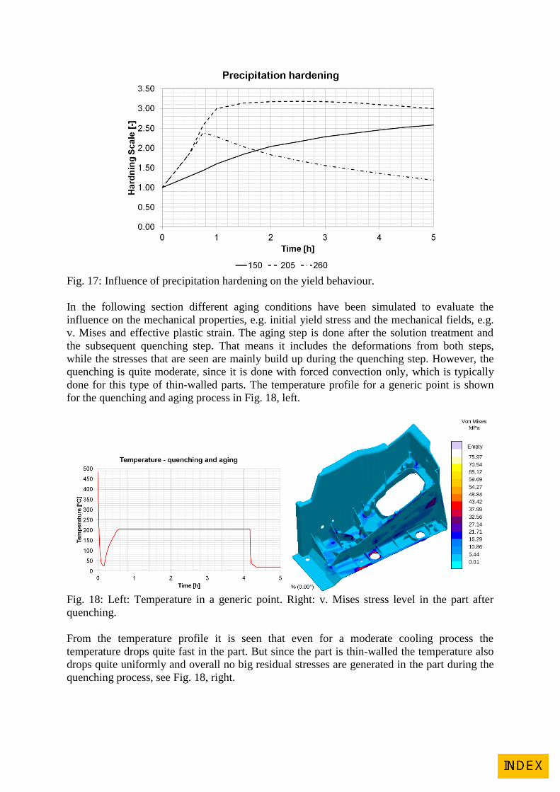
Fig. 17: Influence of precipitation hardening on the yield behaviour.
In the following section different aging conditions have been simulated to evaluate the
influence on the mechanical properties, e.g. initial yield stress and the mechanical fields, e.g.
v. Mises and effective plastic strain. The aging step is done after the solution treatment and
the subsequent quenching step. That means it includes the deformations from both steps,
while the stresses that are seen are mainly build up during the quenching step. However, the
quenching is quite moderate, since it is done with forced convection only, which is typically
done for this type of thin-walled parts. The temperature profile for a generic point is shown
for the quenching and aging process in Fig. 18, left.
Fig. 18: Left: Temperature in a generic point. Right: v. Mises stress level in the part after
quenching.
From the temperature profile it is seen that even for a moderate cooling process the
temperature drops quite fast in the part. But since the part is thin-walled the temperature also
drops quite uniformly and overall no big residual stresses are generated in the part during the
quenching process, see Fig. 18, right.
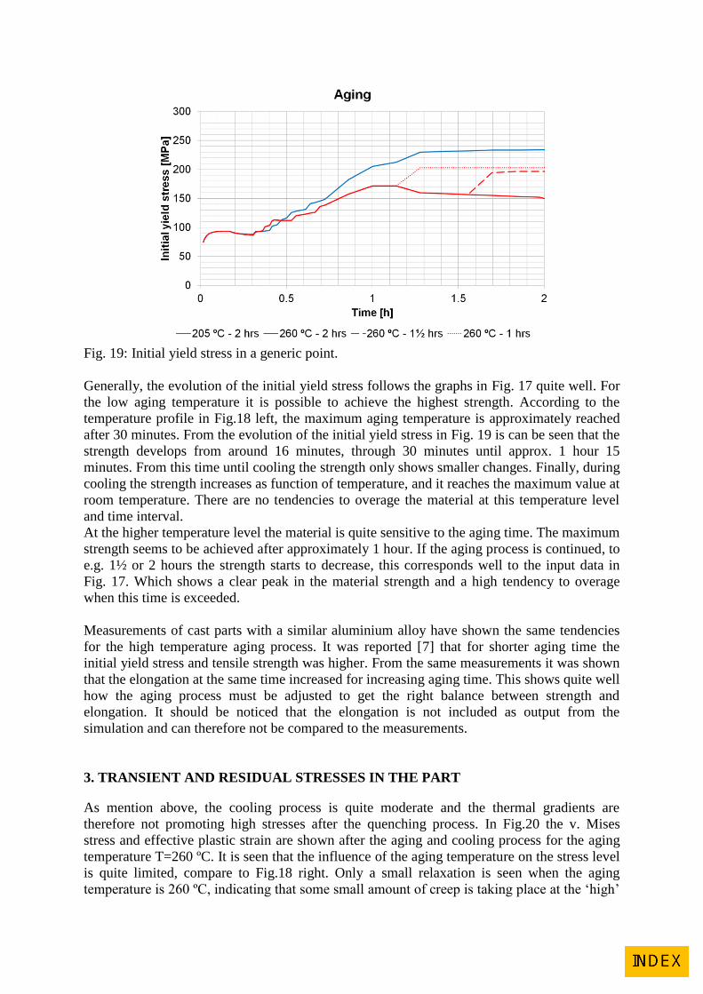
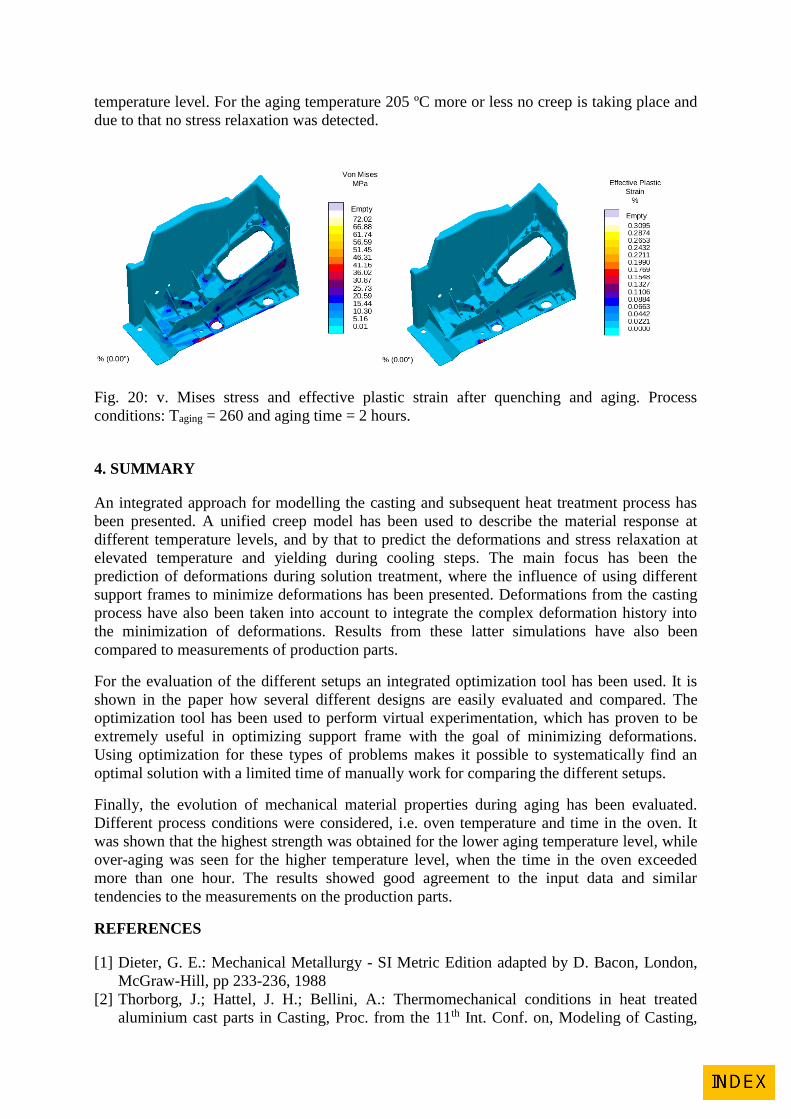
Fig. 19: Initial yield stress in a generic point.
Generally, the evolution of the initial yield stress follows the graphs in Fig. 17 quite well. For
the low aging temperature it is possible to achieve the highest strength. According to the
temperature profile in Fig.18 left, the maximum aging temperature is approximately reached
after 30 minutes. From the evolution of the initial yield stress in Fig. 19 is can be seen that the
strength develops from around 16 minutes, through 30 minutes until approx. 1 hour 15
minutes. From this time until cooling the strength only shows smaller changes. Finally, during
cooling the strength increases as function of temperature, and it reaches the maximum value at
room temperature. There are no tendencies to overage the material at this temperature level
and time interval.
At the higher temperature level the material is quite sensitive to the aging time. The maximum
strength seems to be achieved after approximately 1 hour. If the aging process is continued, to
e.g. 1½ or 2 hours the strength starts to decrease, this corresponds well to the input data in
Fig. 17. Which shows a clear peak in the material strength and a high tendency to overage
when this time is exceeded.
Measurements of cast parts with a similar aluminium alloy have shown the same tendencies
for the high temperature aging process. It was reported [7] that for shorter aging time the
initial yield stress and tensile strength was higher. From the same measurements it was shown
that the elongation at the same time increased for increasing aging time. This shows quite well
how the aging process must be adjusted to get the right balance between strength and
elongation. It should be noticed that the elongation is not included as output from the
simulation and can therefore not be compared to the measurements.
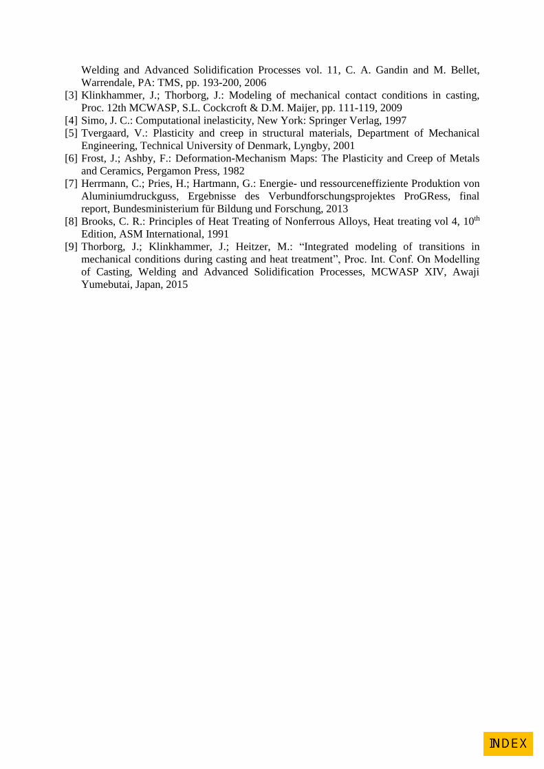
3. TRANSIENT AND RESIDUAL STRESSES IN THE PART
As mention above, the cooling process is quite moderate and the thermal gradients are
therefore not promoting high stresses after the quenching process. In Fig.20 the v. Mises
stress and effective plastic strain are shown after the aging and cooling process for the aging
temperature T=260 ºC. It is seen that the influence of the aging temperature on the stress level
is quite limited, compare to Fig.18 right. Only a small relaxation is seen when the aging
temperature is 260 ºC, indicating that some small amount of creep is taking place at the ‘high’
temperature level. For the aging temperature 205 ºC more or less no creep is taking place and
due to that no stress relaxation was detected.
Fig. 20: v. Mises stress and effective plastic strain after quenching and aging. Process
conditions: Taging = 260 and aging time = 2 hours.
4. SUMMARY
An integrated approach for modelling the casting and subsequent heat treatment process has
been presented. A unified creep model has been used to describe the material response at
different temperature levels, and by that to predict the deformations and stress relaxation at
elevated temperature and yielding during cooling steps. The main focus has been the
prediction of deformations during solution treatment, where the influence of using different
support frames to minimize deformations has been presented. Deformations from the casting
process have also been taken into account to integrate the complex deformation history into
the minimization of deformations. Results from these latter simulations have also been
compared to measurements of production parts.
For the evaluation of the different setups an integrated optimization tool has been used. It is
shown in the paper how several different designs are easily evaluated and compared. The
optimization tool has been used to perform virtual experimentation, which has proven to be
extremely useful in optimizing support frame with the goal of minimizing deformations.
Using optimization for these types of problems makes it possible to systematically find an
optimal solution with a limited time of manually work for comparing the different setups.
Finally, the evolution of mechanical material properties during aging has been evaluated.
Different process conditions were considered, i.e. oven temperature and time in the oven. It
was shown that the highest strength was obtained for the lower aging temperature level, while
over-aging was seen for the higher temperature level, when the time in the oven exceeded
more than one hour. The results showed good agreement to the input data and similar
tendencies to the measurements on the production parts.
REFERENCES
[1] Dieter, G. E.: Mechanical Metallurgy - SI Metric Edition adapted by D. Bacon, London,
McGraw-Hill, pp 233-236, 1988
[2] Thorborg, J.; Hattel, J. H.; Bellini, A.: Thermomechanical conditions in heat treated
aluminium cast parts in Casting, Proc. from the 11th Int. Conf. on, Modeling of Casting,
Welding and Advanced Solidification Processes vol. 11, C. A. Gandin and M. Bellet,
Warrendale, PA: TMS, pp. 193-200, 2006
[3] Klinkhammer, J.; Thorborg, J.: Modeling of mechanical contact conditions in casting,
Proc. 12th MCWASP, S.L. Cockcroft & D.M. Maijer, pp. 111-119, 2009
[4] Simo, J. C.: Computational inelasticity, New York: Springer Verlag, 1997
[5] Tvergaard, V.: Plasticity and creep in structural materials, Department of Mechanical
Engineering, Technical University of Denmark, Lyngby, 2001
[6] Frost, J.; Ashby, F.: Deformation-Mechanism Maps: The Plasticity and Creep of Metals
and Ceramics, Pergamon Press, 1982
[7] Herrmann, C.; Pries, H.; Hartmann, G.: Energie- und ressourceneffiziente Produktion von
Aluminiumdruckguss, Ergebnisse des Verbundforschungsprojektes ProGRess, final
report, Bundesministerium für Bildung und Forschung, 2013
[8] Brooks, C. R.: Principles of Heat Treating of Nonferrous Alloys, Heat treating vol 4, 10th
Edition, ASM International, 1991
[9] Thorborg, J.; Klinkhammer, J.; Heitzer, M.: “Integrated modeling of transitions in
mechanical conditions during casting and heat treatment”, Proc. Int. Conf. On Modelling
of Casting, Welding and Advanced Solidification Processes, MCWASP XIV, Awaji
Yumebutai, Japan, 2015