Embed Size (px)
Citation preview
1234567891011121314151617181920212223242526272829303132333435363738394041424344454647484950
Engineering OptimizationVol. 00, No. 00, Month 2012, 1–19
Design optimization of cold-formed steel portal frames takinginto account the effect of building topology
Duoc T. Phana, James B.P. Lima*, Wei Shaa, Calvin Y.M. Siewb, Tiku T. Tanyimbohb,Honar K. Issac and Fouad A. Mohammadc
aSPACE, Queen’s University, Belfast, UK; bDepartment of Civil Engineering, The University ofStrathclyde, Glasgow, UK; cSchool of Architecture, Design and Built Environment, Nottingham Trent
University, Nottingham, UK
(Received 16 May 2011; final version received 18 February 2012)
Cold-formed steel portal frames are a popular form of construction for low-rise commercial, light industrialand agricultural buildings with spans of up to 20 m. In this article, a real-coded genetic algorithm is describedthat is used to minimize the cost of the main frame of such buildings. The key decision variables consideredin this proposed algorithm consist of both the spacing and pitch of the frame as continuous variables, aswell as the discrete section sizes. A routine taking the structural analysis and frame design for cold-formedsteel sections is embedded into a genetic algorithm. The results show that the real-coded genetic algorithmhandles effectively the mixture of design variables, with high robustness and consistency in achieving theoptimum solution.All wind load combinations according toAustralian code are considered in this research.Results for frames with knee braces are also included, for which the optimization achieved even largersavings in cost.
Keywords: cold-formed steel; portal frames; building topology; real-coded genetic algorithm
1. Introduction
The majority of portal frames use conventional hot-rolled steel sections for the primary load-carrying members (i.e. columns and rafters) and cold-formed steel for the secondary members(i.e. purlins, side rails and cladding). Using hot-rolled steel, spans of up to 60 m can be achieved.For frames of more modest spans, the use of cold-formed steel for the primary load-carryingmembers (i.e. columns and rafters) should be an alternative to conventional hot-rolled steel.
However, because fabrication and erection costs for cold-formed steel are much lower than forhot-rolled steel, there is scope to vary the frame spacing and pitch. Other advantages of cold-formed steel frames compared to hot-rolled steel are as follows. Pregalvanized cold-formed steelsections that do not require painting to prevent rusting are maintenance free. The transportationcosts are lower owing to efficient stacking of cold-formed steel sections. Also, the acquisitioncosts are lower as the cold-formed steel used for the secondary members can be purchased fromthe same manufacturer/supplier.
*Corresponding author. Email: [email protected]
ISSN 0305-215X print/ISSN 1029-0273 online© 2012 Taylor & Francishttp://dx.doi.org/10.1080/0305215X.2012.678493http://www.tandfonline.com
Techset Composition Ltd, Salisbury GENO678493.TeX Page#: 19 Printed: 7/4/2012
51525354555657585960616263646566676869707172737475767778798081828384858687888990919293949596979899100
2 D.T. Phan et al.
Col
our
onlin
e,B
/Win
prin
t
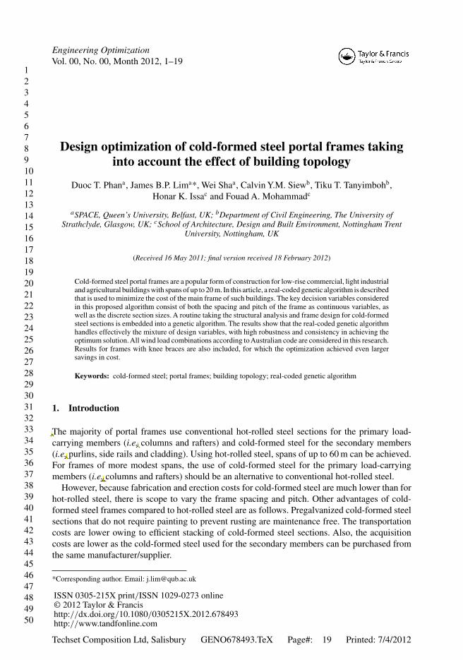
Figure 1. Cold-formed steel portal framing system.
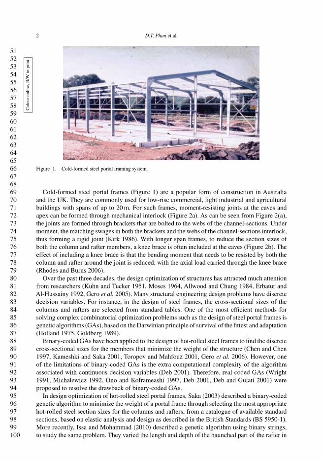
Cold-formed steel portal frames (Figure 1) are a popular form of construction in Australiaand the UK. They are commonly used for low-rise commercial, light industrial and agriculturalbuildings with spans of up to 20 m. For such frames, moment-resisting joints at the eaves andapex can be formed through mechanical interlock (Figure 2a). As can be seen from Figure 2(a),the joints are formed through brackets that are bolted to the webs of the channel-sections. Undermoment, the matching swages in both the brackets and the webs of the channel-sections interlock,thus forming a rigid joint (Kirk 1986). With longer span frames, to reduce the section sizes ofboth the column and rafter members, a knee brace is often included at the eaves (Figure 2b). Theeffect of including a knee brace is that the bending moment that needs to be resisted by both thecolumn and rafter around the joint is reduced, with the axial load carried through the knee brace(Rhodes and Burns 2006).
Over the past three decades, the design optimization of structures has attracted much attentionfrom researchers (Kuhn and Tucker 1951, Moses 1964, Allwood and Chung 1984, Erbatur andAl-Hussainy 1992, Gero et al. 2005). Many structural engineering design problems have discretedecision variables. For instance, in the design of steel frames, the cross-sectional sizes of thecolumns and rafters are selected from standard tables. One of the most efficient methods forsolving complex combinatorial optimization problems such as the design of steel portal frames isgenetic algorithms (GAs), based on the Darwinian principle of survival of the fittest and adaptation(Holland 1975, Goldberg 1989).
Binary-coded GAs have been applied to the design of hot-rolled steel frames to find the discretecross-sectional sizes for the members that minimize the weight of the structure (Chen and Chen1997, Kameshki and Saka 2001, Toropov and Mahfouz 2001, Gero et al. 2006). However, oneof the limitations of binary-coded GAs is the extra computational complexity of the algorithmassociated with continuous decision variables (Deb 2001). Therefore, real-coded GAs (Wright1991, Michalewicz 1992, Ono and Koframeashi 1997, Deb 2001, Deb and Gulati 2001) wereproposed to resolve the drawback of binary-coded GAs.
In design optimization of hot-rolled steel portal frames, Saka (2003) described a binary-codedgenetic algorithm to minimize the weight of a portal frame through selecting the most appropriatehot-rolled steel section sizes for the columns and rafters, from a catalogue of available standardsections, based on elastic analysis and design as described in the British Standards (BS 5950-1).More recently, Issa and Mohammad (2010) described a genetic algorithm using binary strings,to study the same problem. They varied the length and depth of the haunched part of the rafter in
101102103104105106107108109110111112113114115116117118119120121122123124125126127128129130131132133134135136137138139140141142143144145146147148149150
Engineering Optimization 3
Figure 2. Details of eaves joint arrangements: (a) mechanical interlock; (b) knee brace.
a specified range using fixed intervals to determine the optimum size of the haunched member.Hernández et al. (2005) proposed an optimum design software named PADO, based on mathe-matical programming, to optimize the design of a hot-rolled steel portal frame in accordance withthe Spanish code of practice (EA-95). Chen and Hu (2008) used genetic algorithms to optimizehot-rolled steel portal frames having tapered members, according to the Chinese specification forportal frames (CECS-102).
Previous research focused on the design of hot-rolled steel portal frames with fixed topologywhere the pitch and frame spacing were not optimized and were specified a priori. However, the
151152153154155156157158159160161162163164165166167168169170171172173174175176177178179180181182183184185186187188189190191192193194195196197198199200
4 D.T. Phan et al.
optimization of cold-formed steel portal frames with either fixed or variable topology has notbeen considered previously. In this article, a genetic algorithm is proposed to minimize the cost ofcold-formed steel portal frame buildings by minimizing the cost of the main structural elementsper unit length of the building. Although any code of practice can be used the Australian codewas adopted, rather than the UK code, since in Australia the spans of the frames can be larger asthere is less snow.
The optimization method proposed addresses all the relevant combinations of the permanentand imposed loads, incorporates the full range of design constraints and considers all feasible windload combinations. It is assumed here that full lateral restraint is applied to columns and rafters. Itis also assumed that the cost of the purlins, side rails and sheeting is independent of frame spacing.The present research differs from previous work on hot-rolled steel portal frames in that the cross-sectional sizes of the columns and rafters and the topology of the building, including the pitch andframe spacing, are all jointly optimized simultaneously. The decision variables used in the designoptimization are the spacing of the frames; the pitch of the roof ;nd the cross-sectional sizes ofthe main structural elements. Self-evidently, the solution space has both discrete and continuousvariables. Unlike in previous research on hot-rolled steel frames that used binary coding for thegenetic algorithm, real coding is used here.
2. Frame descriptions
2.1. Frame parameters
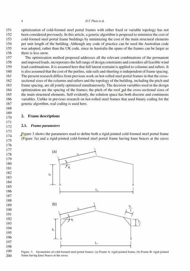
Figure 3 shows the parameters used to define both a rigid-jointed cold-formed steel portal frame(Figure 3a) and a rigid-jointed cold-formed steel portal frame having knee braces at the eaves
(a)
(b)
hf
f
Lf
sf
hf
Lf
fh
3
fh
3sf
f
θ
θ
Figure 3. Geometries of cold-formed steel portal frames: (a) Frame A: rigid-jointed frame; (b) Frame B: rigid-jointedframe having knee braces at the eaves.
201202203204205206207208209210211212213214215216217218219220221222223224225226227228229230231232233234235236237238239240241242243244245246247248249250
Engineering Optimization 5
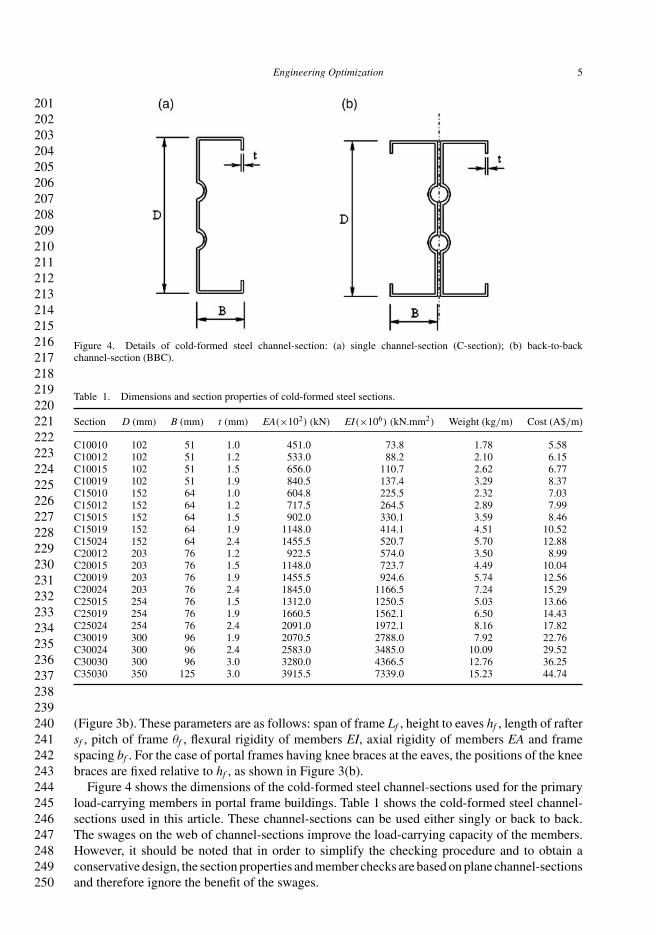
Figure 4. Details of cold-formed steel channel-section: (a) single channel-section (C-section); (b) back-to-backchannel-section (BBC).
Table 1. Dimensions and section properties of cold-formed steel sections.
Section D (mm) B (mm) t (mm) EA(×102) (kN) EI(×106) (kN.mm2) Weight (kg/m) Cost (A$/m)
C10010 102 51 1.0 451.0 73.8 1.78 5.58C10012 102 51 1.2 533.0 88.2 2.10 6.15C10015 102 51 1.5 656.0 110.7 2.62 6.77C10019 102 51 1.9 840.5 137.4 3.29 8.37C15010 152 64 1.0 604.8 225.5 2.32 7.03C15012 152 64 1.2 717.5 264.5 2.89 7.99C15015 152 64 1.5 902.0 330.1 3.59 8.46C15019 152 64 1.9 1148.0 414.1 4.51 10.52C15024 152 64 2.4 1455.5 520.7 5.70 12.88C20012 203 76 1.2 922.5 574.0 3.50 8.99C20015 203 76 1.5 1148.0 723.7 4.49 10.04C20019 203 76 1.9 1455.5 924.6 5.74 12.56C20024 203 76 2.4 1845.0 1166.5 7.24 15.29C25015 254 76 1.5 1312.0 1250.5 5.03 13.66C25019 254 76 1.9 1660.5 1562.1 6.50 14.43C25024 254 76 2.4 2091.0 1972.1 8.16 17.82C30019 300 96 1.9 2070.5 2788.0 7.92 22.76C30024 300 96 2.4 2583.0 3485.0 10.09 29.52C30030 300 96 3.0 3280.0 4366.5 12.76 36.25C35030 350 125 3.0 3915.5 7339.0 15.23 44.74
(Figure 3b). These parameters are as follows: span of frame Lf , height to eaves hf , length of raftersf , pitch of frame θf , flexural rigidity of members EI, axial rigidity of members EA and framespacing bf . For the case of portal frames having knee braces at the eaves, the positions of the kneebraces are fixed relative to hf , as shown in Figure 3(b).
Figure 4 shows the dimensions of the cold-formed steel channel-sections used for the primaryload-carrying members in portal frame buildings. Table 1 shows the cold-formed steel channel-sections used in this article. These channel-sections can be used either singly or back to back.The swages on the web of channel-sections improve the load-carrying capacity of the members.However, it should be noted that in order to simplify the checking procedure and to obtain aconservative design, the section properties and member checks are based on plane channel-sectionsand therefore ignore the benefit of the swages.
251252253254255256257258259260261262263264265266267268269270271272273274275276277278279280281282283284285286287288289290291292293294295296297298299300
6 D.T. Phan et al.
2.2. Frame geometry
In this article, the design optimization of two exemplar frames with Lf of 20 m and hf of 4 m isconsidered: FrameA, without knee braces (Figure 3a), and Frame B, with knee braces (Figure 3b).To minimize the cost per unit length of the building, the decision variables are the pitch, framespacing and cross-section sizes of the members.
It is assumed that the column bases are pinned, and that the purlins and side rails positionedwithin the web of the members are spaced sufficiently close each other to prevent out-of-planebuckling from occurring.
2.3. Frame loading
2.3.1. Permanent and imposed roof loads
The permanent and imposed roof loads (AS/NZS 1170-1 2002b) that will be applied to the framesare as follows:
• permanent load (G): 0.10 kN/m2 (purlins, rails, cladding) and self-weight of the members(Table 1)
• imposed load (Q): 0.25 kN/m2.
2.3.2. Wind loads
From the Australian Standard code of practice on wind loading for the design of buildings(AS/NZS 1170-2 2002c), the basic wind pressure qu for the ultimate limit state is calculatedfrom a design wind speed Vdes, which in turn is calculated from the regional wind speed VR mul-tiplied by factors Md (wind direction multiplier), Mz,cat (terrain/height multiplier), Ms (shieldingmultiplier) and Mt (topographic multiplier). It is worth noting that Mz,cat depends on both theterrain category and the average height of the building.
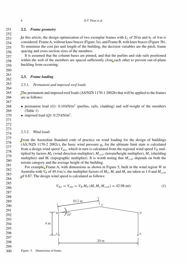
For example, Frame A, with dimensions as shown in Figure 5, built in the wind region W inAustralia with VR of 49.4 m/s, the multiplier factors of Md , Mt and Ms are taken as 1.0 and Mz,cat
of 0.87. The design wind speed is calculated as follows:
Vdes = Vsite = VR.Md .(Mt .Ms.Mz,cat) = 42.98 m/s (1)
4 m
10o
20 m
10.2 m
A
B
C
D
E
Figure 5. Dimensions of frame.
301302303304305306307308309310311312313314315316317318319320321322323324325326327328329330331332333334335336337338339340341342343344345346347348349350
Engineering Optimization 7
where Vsite is the site wind speed and Vdes is the design wind speed; and the basic wind pressure:
qu = 0.6 × V 2des
1000= 1.1 kN/m2 (2)
where qu is the ultimate design wind pressure.The design wind pressure acting on each of the four faces of the frame (AB, BC, CD and
DE) is obtained by multiplying qu by a coefficient of pressure and other related factors. Thecoefficient of pressure acting on each face is obtained from a combination of the external pressurecoefficient Cpe and the internal pressure coefficient Cpi. The external pressure coefficients Cpe
should be calculated for wind acting on the side and on the end. These values are shown inTable 2, calculated based on AS/NZS 1170-2 (2002c).
For buildings of normal permeability without dominant openings, Cpi has a minimum value of−0.3 for suction and a maximum value of 0.2 for pressure.
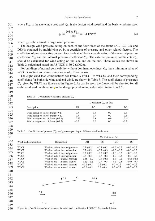
The eight wind load combinations for Frame A (WLC1 to WLC8), and their correspondingcoefficients for both side wind and end wind, are shown in Table 3. The coefficients of pressuresCpe given by WLC1 are illustrated in Figure 6. As can be seen, the frame will be checked for alleight wind load combinations in the design procedure to be described in Section 2.5.
Table 2. Coefficients of external pressure Cpe.
Coefficient Cpe on face
Description AB BC CD DE
Wind acting on side of frame (WT1) 0.7 –0.3 –0.3 –0.3Wind acting on side of frame (WT2) 0.7 –0.7 –0.3 –0.3Wind acting on end of frame (WL1) –0.65 –0.9 –0.9 –0.65Wind acting on end of frame (WL2) –0.2 0.2 0.2 –0.2
Table 3. Coefficients of pressure (Cpe + Cpi) corresponding to different wind load cases.
Coefficient on face
Wind load combination Description AB BC CD DE
WLC1 Wind on side + internal pressure 0.7 +0.2 −0.3 +0.2 −0.3 +0.2 −0.3 +0.2WLC2 Wind on side + internal suction 0.7 −0.3 −0.3 −0.3 −0.3 −0.3 −0.3 −0.3WLC3 Wind on side + internal pressure 0.7 +0.2 −0.7 +0.2 −0.3 +0.2 −0.3 +0.2WLC4 Wind on side + internal suction 0.7 −0.3 −0.7 −0.3 −0.3 −0.3 −0.3 −0.3WLC5 Wind on end + internal pressure −0.65 +0.2 −0.9 +0.2 −0.9 +0.2 −0.65 +0.2WLC6 Wind on end + internal suction −0.65 −0.3 −0.9 −0.3 −0.9 −0.3 −0.65 −0.3WLC7 Wind on end + internal pressure −0.2 +0.2 0.2 +0.2 0.2 +0.2 −0.2 +0.2WLC8 Wind on end + internal suction −0.2 −0.3 0.2 −0.3 0.2 −0.3 −0.2 −0.3
0.7 0.3
0.3 0.3
A
B
E
D
C
Figure 6. Coefficients of wind pressure for wind load combination 1 (WLC1) for standard frame.
351352353354355356357358359360361362363364365366367368369370371372373374375376377378379380381382383384385386387388389390391392393394395396397398399400
8 D.T. Phan et al.
2.3.3. Limit state design
In accordance with AS/NZS 1170-0 (2002a), the frame will be checked at the ultimate limit statefor the following three ultimate load combinations:
ULC1 = 1.2G + 1.5Q
ULC2 = 1.2G + WLC (3)
ULC3 = 0.9G + WLC
It should be noted that ULC3 is used for the uplift wind load combination.
2.4. Frame analysis
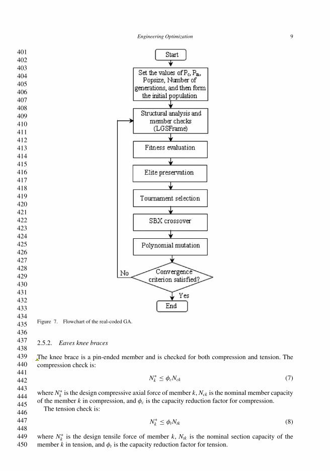
A first order elastic frame analysis program, written by the authors for cold-formed steel sections,referred as LGSFrame, is used to analyse and design the portal frame. To take into account secondorder effects, an amplification factor is applied as described in the Australian code of practice.For each load combination, the bending moment, shear force and axial force are determined.LGSFrame is called to analyse each candidate solution in each generation as shown in Figure 7.
2.5. Member checks
2.5.1. Columns and rafters
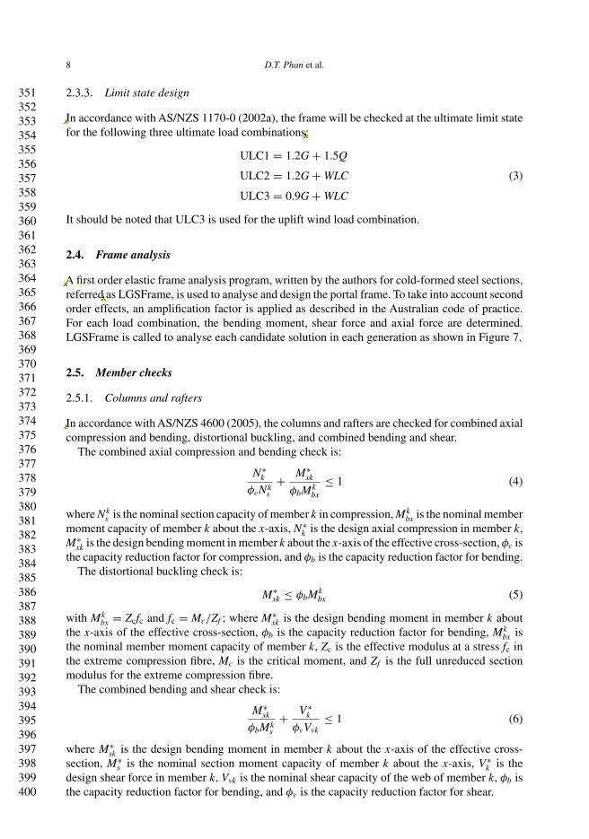
In accordance with AS/NZS 4600 (2005), the columns and rafters are checked for combined axialcompression and bending, distortional buckling, and combined bending and shear.
The combined axial compression and bending check is:
N∗k
φcNks
+ M∗xk
φbMkbx
≤ 1 (4)
where Nks is the nominal section capacity of member k in compression, Mk
bx is the nominal membermoment capacity of member k about the x-axis, N∗
k is the design axial compression in member k,M∗
xk is the design bending moment in member k about the x-axis of the effective cross-section, φc isthe capacity reduction factor for compression, and φb is the capacity reduction factor for bending.
The distortional buckling check is:
M∗xk ≤ φbMk
bx (5)
with Mkbx = Zcfc and fc = Mc/Zf ; where M∗
xk is the design bending moment in member k aboutthe x-axis of the effective cross-section, φb is the capacity reduction factor for bending, Mk
bx isthe nominal member moment capacity of member k, Zc is the effective modulus at a stress fc inthe extreme compression fibre, Mc is the critical moment, and Zf is the full unreduced sectionmodulus for the extreme compression fibre.
The combined bending and shear check is:
M∗xk
φbMks
+ V∗k
φvVvk≤ 1 (6)
where M∗sk is the design bending moment in member k about the x-axis of the effective cross-
section, M∗s is the nominal section moment capacity of member k about the x-axis, V∗
k is thedesign shear force in member k, Vvk is the nominal shear capacity of the web of member k, φb isthe capacity reduction factor for bending, and φv is the capacity reduction factor for shear.
401402403404405406407408409410411412413414415416417418419420421422423424425426427428429430431432433434435436437438439440441442443444445446447448449450
Engineering Optimization 9
Figure 7. Flowchart of the real-coded GA.
2.5.2. Eaves knee braces
The knee brace is a pin-ended member and is checked for both compression and tension. Thecompression check is:
N∗k ≤ φcNck (7)
where N∗k is the design compressive axial force of member k, Nck is the nominal member capacity
of the member k in compression, and φc is the capacity reduction factor for compression.The tension check is:
N∗k ≤ φtNtk (8)
where N∗k is the design tensile force of member k, Ntk is the nominal section capacity of the
member k in tension, and φt is the capacity reduction factor for tension.
451452453454455456457458459460461462463464465466467468469470471472473474475476477478479480481482483484485486487488489490491492493494495496497498499500
10 D.T. Phan et al.
3. Optimization formulation
The objective of the design optimization is to determine the portal frame building having theminimum cost, while satisfying the design requirements. The cost of the main frame depends onframe spacing, pitch and cross-section sizes. The objective function can be expressed in terms ofthe cost per unit length of the building as follows:
Minimize W = 1
bf
n∑i=1
wili (9)
where W is the cost of main frame per unit length of building, bf is the frame spacing, wi are thecost per unit length of cold-formed steel sections (Table 1), li are the lengths of cold-formed steelstructural members, and n is the number of members.
The normalized forms of the design constraints or unity factors given in Equations (4)–(8) areexpressed as follows:
g1 = N∗k
φcNks
+ M∗xk
φbMkbx
− 1 ≤ 0 (10a)
g2 = M∗sk
φbMkb
− 1 ≤ 0 (10b)
g3 = M∗k
φbMks
+ V∗k
φvVvk− 1 ≤ 0 (10c)
g4 = N∗k
φcNck− 1 ≤ 0 (10d)
g5 = N∗k
φtNtk− 1 ≤ 0 (10e)
The design specification is the ultimate limit state (ULS) that constitutes the constraints forthe optimization problem. Penalty functions are required to define the relationship between theobjective function and constraints and to transform a constrained problem to an unconstrainedone (Camp et al. 1998, Pezeshk et al. 2000). The relationship known as the fitness function oftenhas the form:
F = W [1 + C] (11)
where F is the fitness function, W is the objective function, being the cost of frame per unit lengthof building, and C is the constraint violation penalty.
In this research, the penalty value is assigned through the maximum level of violation of theunity-factor constraints in Equations (10a)–(10e) as follows:
g = max [g1, g2, g3, g4, g5] (12)
In this article, penalty values are imposed empirically, in proportion to the severity of constraintviolation. Through a numbers of trials, it is observed that two levels of violated constraints withthe magnitudes as shown in Equation(13) are suitable to eliminate the violated solutions through
501502503504505506507508509510511512513514515516517518519520521522523524525526527528529530531532533534535536537538539540541542543544545546547548549550
Engineering Optimization 11
Col
our
onlin
e,B
/Win
prin
t
0
100
200
300
400
500
600
700
800
0 5000 10000 15000 20000Number of function evaluations
Uni
t cos
t (A
$/m
)
Popsize 100
Popsize 120
Popsize 160
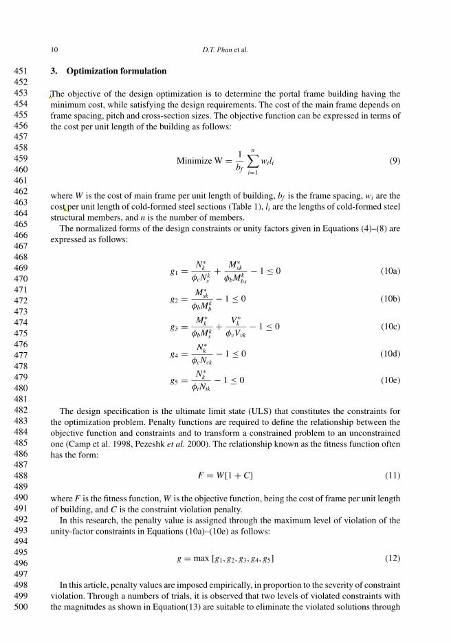
Figure 8. Progress of the GA for Frame A with fixed pitch and frame spacing.
the evolutionary process, as follows:
C =
⎧⎪⎨⎪⎩
0 if g ≤ 0
g if 0 < g ≤ 0.5
10g if g > 0.5
(13)
The proposed optimization procedure aims to minimize the value of the fitness function F(Equation 11). This is achieved by minimizing the cost W and reducing the penalty C to zero. Theprocedure involves a real-coded GA, frame analysis and cold-formed steel design. As can be seenfrom Figure 8, the evaluation process computes the fitness function values using the objectivefunction (Equation 9) along with the corresponding penalty values defined in Equation (13).Better (i.e. cheaper) solutions will yield smaller fitness values, and consequently are selectedpreferentially by the tournament selection operator. The criterion for terminating the programis a predefined total number of function evaluations. This criterion is suitable to investigate theconvergence history of the algorithm.
4. Real-coded genetic algorithm
The characteristic of real-coded GAs is that genetic operators are directly applied to the designvariables without coding and decoding as with binary GAs. Solving optimization problems usingreal-coded GAs is therefore less cumbersome when compared to the binary-coded GAs. Thealgorithm used in this article randomly generates a set of solutions known as the initial population.From this population, the next generation of solutions is evolved by conducting three geneticoperations: selection, crossover and mutation. The flowchart of the real-coded GA used in thisarticle is shown in Figure 7.
4.1. Selection and elitism strategy
In tournament selection operator, the process is conducted by picking at random two solutionsfrom the current population to compare their fitness values. The solution with a better fitnessvalue is selected for the next operation. The process of random selection ensures that the bestsolutions in the population will not dominate the mating pool, as in the proportional selection
551552553554555556557558559560561562563564565566567568569570571572573574575576577578579580581582583584585586587588589590591592593594595596597598599600
12 D.T. Phan et al.
method. The diversity of the population is thus preserved to increase the exploration componentof the algorithm.
The best individuals in the population, depending on the adopted percentage of population, areretained and carried forward unchanged to the next generation. The rest of the new population iscreated by the three genetic operators of selection, crossover and mutation applied to the entirecurrent population including elite individuals.
4.2. Real-coded crossover and mutation operators
With real coding, the difficulty is how to use a pair of real-coded decision variable vectors toproduce a new pair of offspring vectors or how to mutate a real decision variable vector in ameaningful manner (Deb 2001). In this article, the simulated binary crossover (SBX) (Deb andAgrawal 1995) and polynomial mutation (Deb 1997, Deb and Gulati 2001) are applied to createthe new individuals for the next generation.
The SBX operator picks at random two solutions in the current population, known as parents,to create two offspring symmetrically to avoid a bias toward any particular parent solution in asingle crossover operation. The formulation used for SBX is as follows:
x(1,t+1)i = 0.5[(1 + β)x(1,t)
i + (1 − β)x(2,t)i ]
x(2,t+1)i = 0.5[(1 − β)x(1,t)
i + (1 + β)x(2,t)i ]
(14)
where β is the probability distribution function for crossover, x(1,t)i and x(2,t)
i are the parentsolutions, and x(1,t+1)
i and x(2,t+1)i are the children created for the next generation.
To ensure that the new values of the decision variable remain within the range [xli , xu
i ], where xli
and xui are the lower and upper bounds, respectively, the probability distribution for the crossover
operator has the form:
β(ηc) ={
[αu]1/(ηc+1) if u ≤ 1/α,
[1/2 − αu]1/(ηc+1) if 1/α < u ≤ 1(15)
where u is a random number between 0 and 1, ηc is the distribution index for crossover, α =2 − χ−(ηc+1), and χ is calculated as follows:
χ = 1 + 2
x(2,t)i − x(1,t)
i
min[(x(1,t)
i − xli), (x
ui − x(2,t)
i )]
; assuming x(1,t)i < x(2,t)
i
Like in the SBX operator, polynomial mutation also uses probability distribution δ̄(ηm), being apolynomial function to create the child solution in the vicinity of a parent solution. The formulationfor the mutation operator (Deb 1997, Deb and Gulati 2001) has the form:
y(1,t+1)i = x(1,t+1)
i + (xui − xl
i)δ̄ (16)
where xui and xl
i are the boundaries of decision variables, and y(1,t+1)i is a new solution obtained
from the mutation operator.To ensure that no solution would be created outside the range of xu
i and xli (Deb and Gulati
2001), the parameter δ̄(ηm) has the following form:
δ̄ ={[
2u + (1 − 2u)(1 − δ)ηm+1]1/(ηm+1) − 1 if u ≤ 0.5,
1 − [2(1 − u) + 2(u − 0.5)(1 − δ)ηm+1
]1/(ηm+1)if 0.5 < u ≤ 1
(17)
where u is a random number between 0 and 1, ηm is the distribution index for mutation, andδ = min
[(x(1,t+1) − xl
i), (xui − x(1,t+1))
]/(xu
i − xli).
601602603604605606607608609610611612613614615616617618619620621622623624625626627628629630631632633634635636637638639640641642643644645646647648649650
Engineering Optimization 13
In this article, ηm = ηc = 1 is used. A technique that rounds off the number in dealing withdiscrete design variables is used in case SBX crossover or polynomial mutation create decimalnumbers. Constant probabilities are assigned to both crossover and mutation operators to reducethe possibility of destroying the good solutions. Based on a number of trials, a crossover probabilityPc of 0.9 was used throughout in this study. It was observed that premature convergence happenedwith a low mutation probability. To increase the GA’s exploration capacity in the solution spaceto increase the chance of locating the optimum solution, the mutation probability Pm is tunedempirically as high as 0.1.
5. Design examples
5.1. Frame A with fixed topology
5.1.1. Exhaustive enumeration
Frame A, without knee braces, in which the pitch is 10◦ and frame spacing is 4 m, is considered.Such a typical pitch and frame spacing are commonly used for cold-formed steel portal frames.This design problem has two discrete decision variables. The optimum cross-sections for thecolumns and rafters can be determined from the cross-sections shown in Table 1 by exhaustiveenumeration using the LGSFrame as mentioned in Section 2.4. As can be seen from the list ofcold-formed steel channel-sections, there are 40 options of cold-formed cross-sections used formembers, including both single sections (C) and back-to-back channel-sections (BBC).
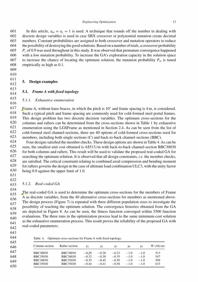
Four designs satisfied the member checks. These design options are shown in Table 4. As can beseen, the smallest unit cost obtained is A$513/m with back-to-back channel-section BBC30030for both columns and rafters. This result will be used to validate the proposed real-coded GA forsearching the optimum solution. It is observed that all design constraints, i.e. the member checks,are satisfied. The critical constraint relating to combined axial compression and bending momentfor rafters governs the design in the case of ultimate load combination ULC3, with the unity factorbeing 0.9 against the upper limit of 1.0.
5.1.2. Real-coded GA
The real-coded GA is used to determine the optimum cross-sections for the members of FrameA as discrete variables, from the 40 alternative cross-sections for members as mentioned above.The design process (Figure 7) is repeated with three different population sizes to investigate thepossibility of reaching the optimum solution. The convergence histories obtained from the GAare depicted in Figure 8. As can be seen, the fitness function converged within 5500 functionevaluations. The three runs in the optimization process lead to the same minimum-cost solutionas the exhaustive enumeration process. This result proves the reliability of the proposed GA withreal-coded parameters.
Table 4. Optimum cross-sections for Frame A with fixed topology.
Column section Rafter section g1 g2 g3 g4 g5 W (A$/m)
BBC30030 BBC30030 −0.30 −0.28 −0.32 −1.0 −1.0 513BBC35030 BBC30030 −0.32 −0.30 −0.35 −1.0 −1.0 547BBC30030 BBC35030 −0.35 −0.45 −0.59 −1.0 −1.0 599BBC35030 BBC35030 −0.44 −0.41 −0.58 −1.0 −1.0 633
651652653654655656657658659660661662663664665666667668669670671672673674675676677678679680681682683684685686687688689690691692693694695696697698699700
14 D.T. Phan et al.
0
100
200
300
400
500
600
700
800
5 10 15 20 25 30
Pitch (degree)
Uni
t cos
t (A
$/m
)
Figure 9. Effect of pitch on unit cost of Frame A with fixed frame spacing.
5.2. Frame A with variable pitch
5.2.1. Exhaustive enumeration
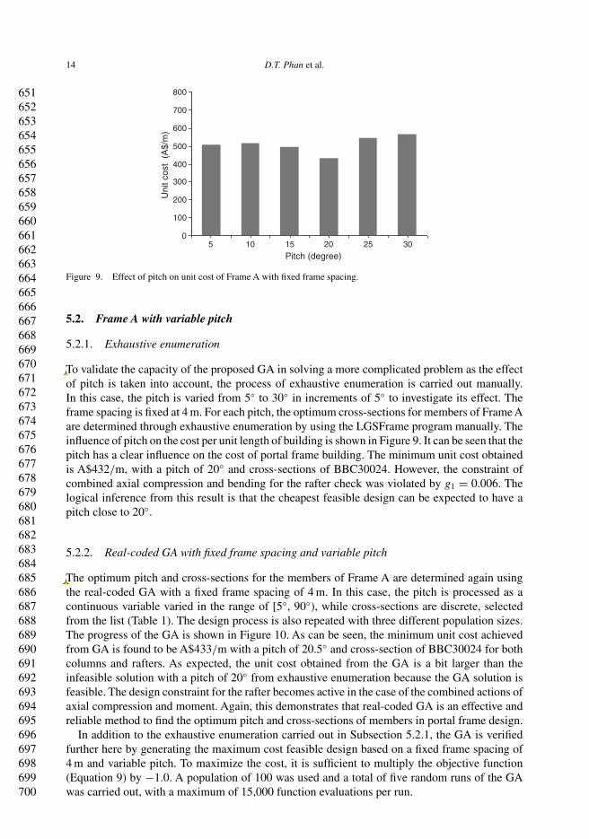
To validate the capacity of the proposed GA in solving a more complicated problem as the effectof pitch is taken into account, the process of exhaustive enumeration is carried out manually.In this case, the pitch is varied from 5◦ to 30◦ in increments of 5◦ to investigate its effect. Theframe spacing is fixed at 4 m. For each pitch, the optimum cross-sections for members of Frame Aare determined through exhaustive enumeration by using the LGSFrame program manually. Theinfluence of pitch on the cost per unit length of building is shown in Figure 9. It can be seen that thepitch has a clear influence on the cost of portal frame building. The minimum unit cost obtainedis A$432/m, with a pitch of 20◦ and cross-sections of BBC30024. However, the constraint ofcombined axial compression and bending for the rafter check was violated by g1 = 0.006. Thelogical inference from this result is that the cheapest feasible design can be expected to have apitch close to 20◦.
5.2.2. Real-coded GA with fixed frame spacing and variable pitch
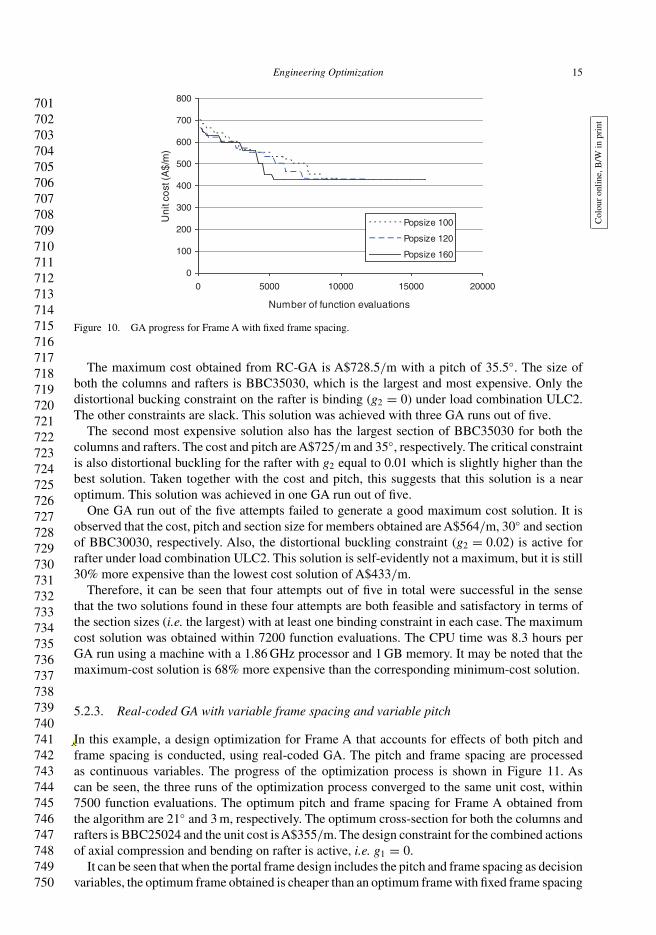
The optimum pitch and cross-sections for the members of Frame A are determined again usingthe real-coded GA with a fixed frame spacing of 4 m. In this case, the pitch is processed as acontinuous variable varied in the range of [5◦, 90◦), while cross-sections are discrete, selectedfrom the list (Table 1). The design process is also repeated with three different population sizes.The progress of the GA is shown in Figure 10. As can be seen, the minimum unit cost achievedfrom GA is found to be A$433/m with a pitch of 20.5◦ and cross-section of BBC30024 for bothcolumns and rafters. As expected, the unit cost obtained from the GA is a bit larger than theinfeasible solution with a pitch of 20◦ from exhaustive enumeration because the GA solution isfeasible. The design constraint for the rafter becomes active in the case of the combined actions ofaxial compression and moment. Again, this demonstrates that real-coded GA is an effective andreliable method to find the optimum pitch and cross-sections of members in portal frame design.
In addition to the exhaustive enumeration carried out in Subsection 5.2.1, the GA is verifiedfurther here by generating the maximum cost feasible design based on a fixed frame spacing of4 m and variable pitch. To maximize the cost, it is sufficient to multiply the objective function(Equation 9) by −1.0. A population of 100 was used and a total of five random runs of the GAwas carried out, with a maximum of 15,000 function evaluations per run.
701702703704705706707708709710711712713714715716717718719720721722723724725726727728729730731732733734735736737738739740741742743744745746747748749750
Engineering Optimization 15
Col
our
onlin
e,B
/Win
prin
t
0
100
200
300
400
500
600
700
800
0 5000 10000 15000 20000
Number of function evaluations
Un
it co
st (
A$
/m)
Popsize 100
Popsize 120
Popsize 160
Figure 10. GA progress for Frame A with fixed frame spacing.
The maximum cost obtained from RC-GA is A$728.5/m with a pitch of 35.5◦. The size ofboth the columns and rafters is BBC35030, which is the largest and most expensive. Only thedistortional bucking constraint on the rafter is binding (g2 = 0) under load combination ULC2.The other constraints are slack. This solution was achieved with three GA runs out of five.
The second most expensive solution also has the largest section of BBC35030 for both thecolumns and rafters. The cost and pitch are A$725/m and 35◦, respectively. The critical constraintis also distortional buckling for the rafter with g2 equal to 0.01 which is slightly higher than thebest solution. Taken together with the cost and pitch, this suggests that this solution is a nearoptimum. This solution was achieved in one GA run out of five.
One GA run out of the five attempts failed to generate a good maximum cost solution. It isobserved that the cost, pitch and section size for members obtained are A$564/m, 30◦ and sectionof BBC30030, respectively. Also, the distortional buckling constraint (g2 = 0.02) is active forrafter under load combination ULC2. This solution is self-evidently not a maximum, but it is still30% more expensive than the lowest cost solution of A$433/m.
Therefore, it can be seen that four attempts out of five in total were successful in the sensethat the two solutions found in these four attempts are both feasible and satisfactory in terms ofthe section sizes (i.e. the largest) with at least one binding constraint in each case. The maximumcost solution was obtained within 7200 function evaluations. The CPU time was 8.3 hours perGA run using a machine with a 1.86 GHz processor and 1 GB memory. It may be noted that themaximum-cost solution is 68% more expensive than the corresponding minimum-cost solution.
5.2.3. Real-coded GA with variable frame spacing and variable pitch
In this example, a design optimization for Frame A that accounts for effects of both pitch andframe spacing is conducted, using real-coded GA. The pitch and frame spacing are processedas continuous variables. The progress of the optimization process is shown in Figure 11. Ascan be seen, the three runs of the optimization process converged to the same unit cost, within7500 function evaluations. The optimum pitch and frame spacing for Frame A obtained fromthe algorithm are 21◦ and 3 m, respectively. The optimum cross-section for both the columns andrafters is BBC25024 and the unit cost is A$355/m. The design constraint for the combined actionsof axial compression and bending on rafter is active, i.e. g1 = 0.
It can be seen that when the portal frame design includes the pitch and frame spacing as decisionvariables, the optimum frame obtained is cheaper than an optimum frame with fixed frame spacing
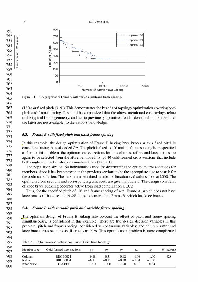
751752753754755756757758759760761762763764765766767768769770771772773774775776777778779780781782783784785786787788789790791792793794795796797798799800
16 D.T. Phan et al.
Col
our
onlin
e,B
/Win
prin
t
0
100
200
300
400
500
600
700
800
0 5000 10000 15000 20000
Number of function evaluations
Uni
t cos
t (A
$/m
)
Popsize 100
Popsize 120
Popsize 160
Figure 11. GA progress for Frame A with variable pitch and frame spacing.
(18%) or fixed pitch (31%). This demonstrates the benefit of topology optimization covering bothpitch and frame spacing. It should be emphasized that the above-mentioned cost savings relateto the typical frame geometry, and not to previously optimized results described in the literature;the latter are not available, to the authors’ knowledge.
5.3. Frame B with fixed pitch and fixed frame spacing
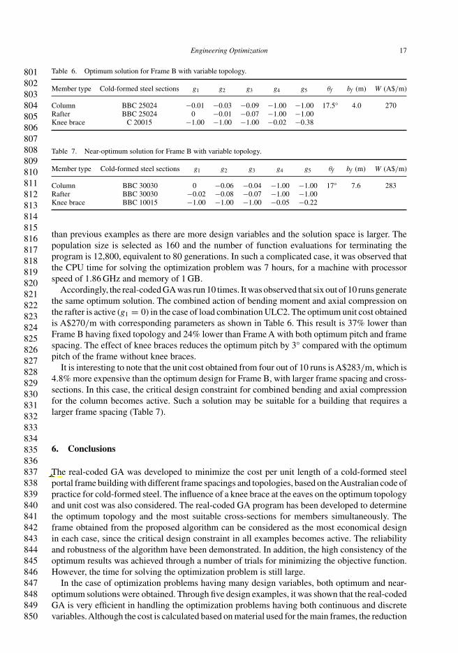
In this example, the design optimization of Frame B having knee braces with a fixed pitch isconsidered using the real-coded GA. The pitch is fixed as 10◦ and the frame spacing is prespecifiedas 4 m. In this problem, the optimum cross-sections for the columns, rafters and knee braces areagain to be selected from the aforementioned list of 40 cold-formed cross-sections that includeboth single and back-to-back channel-sections (Table 1).
The population size of 160 individuals is used for determining the optimum cross-sections formembers, since it has been proven in the previous sections to be the appropriate size to search forthe optimum solution. The maximum permitted number of function evaluations is set at 8000. Theoptimum cross-sections and corresponding unit costs are given in Table 5. The design constraintof knee brace buckling becomes active from load combination ULC2.
Thus, for the specified pitch of 10◦ and frame spacing of 4 m, Frame A, which does not haveknee braces at the eaves, is 19.8% more expensive than Frame B, which has knee braces.
5.4. Frame B with variable pitch and variable frame spacing
The optimum design of Frame B, taking into account the effect of pitch and frame spacingsimultaneously, is considered in this example. There are five design decision variables in thisproblem: pitch and frame spacing, considered as continuous variables; and column, rafter andknee brace cross-sections as discrete variables. This optimization problem is more complicated
Table 5. Optimum cross-sections for Frame B with fixed topology.
Member type Cold-formed steel sections g1 g2 g3 g4 g5 W (A$/m)
Column BBC 30024 −0.18 −0.31 −0.12 −1.00 −1.00 428Rafter BBC 30024 −0.12 −0.13 −0.10 −1.00 −1.00Knee brace C 20015 −1.00 −1.00 −1.00 0 −0.34
801802803804805806807808809810811812813814815816817818819820821822823824825826827828829830831832833834835836837838839840841842843844845846847848849850
Engineering Optimization 17
Table 6. Optimum solution for Frame B with variable topology.
Member type Cold-formed steel sections g1 g2 g3 g4 g5 θf bf (m) W (A$/m)
Column BBC 25024 −0.01 −0.03 −0.09 −1.00 −1.00 17.5◦ 4.0 270Rafter BBC 25024 0 −0.01 −0.07 −1.00 −1.00Knee brace C 20015 −1.00 −1.00 −1.00 −0.02 −0.38
Table 7. Near-optimum solution for Frame B with variable topology.
Member type Cold-formed steel sections g1 g2 g3 g4 g5 θf bf (m) W (A$/m)
Column BBC 30030 0 −0.06 −0.04 −1.00 −1.00 17◦ 7.6 283Rafter BBC 30030 −0.02 −0.08 −0.07 −1.00 −1.00Knee brace BBC 10015 −1.00 −1.00 −1.00 −0.05 −0.22
than previous examples as there are more design variables and the solution space is larger. Thepopulation size is selected as 160 and the number of function evaluations for terminating theprogram is 12,800, equivalent to 80 generations. In such a complicated case, it was observed thatthe CPU time for solving the optimization problem was 7 hours, for a machine with processorspeed of 1.86 GHz and memory of 1 GB.
Accordingly, the real-coded GA was run 10 times. It was observed that six out of 10 runs generatethe same optimum solution. The combined action of bending moment and axial compression onthe rafter is active (g1 = 0) in the case of load combination ULC2. The optimum unit cost obtainedis A$270/m with corresponding parameters as shown in Table 6. This result is 37% lower thanFrame B having fixed topology and 24% lower than Frame A with both optimum pitch and framespacing. The effect of knee braces reduces the optimum pitch by 3◦ compared with the optimumpitch of the frame without knee braces.
It is interesting to note that the unit cost obtained from four out of 10 runs is A$283/m, which is4.8% more expensive than the optimum design for Frame B, with larger frame spacing and cross-sections. In this case, the critical design constraint for combined bending and axial compressionfor the column becomes active. Such a solution may be suitable for a building that requires alarger frame spacing (Table 7).
6. Conclusions
The real-coded GA was developed to minimize the cost per unit length of a cold-formed steelportal frame building with different frame spacings and topologies, based on theAustralian code ofpractice for cold-formed steel. The influence of a knee brace at the eaves on the optimum topologyand unit cost was also considered. The real-coded GA program has been developed to determinethe optimum topology and the most suitable cross-sections for members simultaneously. Theframe obtained from the proposed algorithm can be considered as the most economical designin each case, since the critical design constraint in all examples becomes active. The reliabilityand robustness of the algorithm have been demonstrated. In addition, the high consistency of theoptimum results was achieved through a number of trials for minimizing the objective function.However, the time for solving the optimization problem is still large.
In the case of optimization problems having many design variables, both optimum and near-optimum solutions were obtained. Through five design examples, it was shown that the real-codedGA is very efficient in handling the optimization problems having both continuous and discretevariables.Although the cost is calculated based on material used for the main frames, the reduction
851852853854855856857858859860861862863864865866867868869870871872873874875876877878879880881882883884885886887888889890891892893894895896897898899900
18 D.T. Phan et al.
is very remarkable when the optimum topology is reached. It is also shown that frames havingknee braces result in the most optimum design with the least cost of material.
In further research, the position of the purlins and side rails and their cost will be consid-ered, taking into account buckling of the column and rafter members between points of lateralrestraint. Techniques to enhance real-coded GA to reduce the computing time will also beconsidered.
Acknowledgements
The financial support from the Queen’s University Belfast is gratefully acknowledged.
References
Allwood, R.J. and Chung, Y.S., 1984. Minimum weight design of trusses by an optimality criteria method. InternationalJournal of Numerical Methods in Engineering, 20, 697–713.
Australian/New Zealand Standard™, 2002a. AS/NZS 1170-0. Structural design actions—Part 0: General principles.Q1Australian/New Zealand Standard™, 2002b. AS/NZS 1170-1. Structural design actions—Part 1: Permanent, imposed
and other actions.Australian/New Zealand Standard™, 2002c. AS/NZS 1170-2. Structural design actions—Part 2: Wind actions.Australian/New Zealand Standard™, 2005. AS/NZS 4600:2005. Cold-formed steel structures.Camp, C., Pezeshk, S., and Cao, G., 1998. Optimum design of two dimensional structures using genetic algorithm. Journal
of Structural Engineering ASCE, 124 (5), 551–559.Chen, T.Y. and Chen, C.J., 1997. Improvement of simple genetic algorithm in structural design. International Journal of
Numerical Methods in Engineering, 40, 1323–1334.Chen, Y. and Hu, K., 2008. Optimal design of steel portal frames based on genetic algorithms. Journal of Architecture
and Civil Engineering China, 2 (4), 318–322.Deb, K., 1997. Mechanical component design using genetic algorithms. In: D. Dasgupta and Z. Michalewicz,
eds.Evolutionary algorithms in engineering applications. New York: Springer, 495–512.Deb, K., 2001. Multi-objective optimization using evolutionary algorithms. Chichester: John Wiley and Sons.Deb, K. and Agrawal, R. B., 1995. Simulated binary crossover for continuous space. Complex Systems, 9 (2),
115–148.Deb, K. and Gulati, S., 2001. Design of truss-structures for minimum weight using genetic algorithms. Finite Element in
Analysis and Design, 37, 447–465.Erbatur, F. and Al-Hussainy, M.M., 1992. Optimum design of frames. Journal of Computers and Structures, 45 (5),
887–891.Gero, M.B.P., García, A.B., and del Coz Díaz, J.J., 2005. A modified elitist genetic algorithm applied to the design
optimization of complex steel structures. Journal of Constructional Steel Research, 61 (2), 265–280.Gero, M.B.P., García, A.B., and del Coz Díaz, J.J., 2006. Design optimization of 3D steel structures: genetic algorithms
vs. classical techniques. Journal of Constructional Steel Research, 62 (12), 1303–1309.Goldberg, D.E., 1989. Genetic algorithms in search, optimization and machine learning. New York: Addison-Wesley.Hernández, S., et al., 2005. Design optimization of steel portal frames. Journal of Advances in Engineering Software, 36,
626–633.Holland, J.H., 1975. Adaptation in natural and artificial systems. Ann Arbor, MI: University of Michigan Press.Issa, H.K. and Mohammad, F.A., 2010. Effect of mutation schemes on convergence to optimum design of steel frames.
Journal of Constructional Steel Research, 66 (7), 954–961.Kameshki, E. and Saka, M.P., 2001. Optimum design of nonlinear steel frames with semi-rigid connections using a genetic
algorithm. Journal of Computers and Structures, 79, 1593–1604.Kirk, P., 1986. Design of a cold-formed section portal frame building system. In: W.W.Yu and J.H. Senne, eds. Proceedings
of the 8th international specialty conference on cold-formed steel structures, 11–12 November 1986 St Louis.Missouri: University of Missouri-Rolla, 295–310.
Kuhn, H.W. and Tucker, A.W., 1951. Nonlinear programming. In: Proceedings of the 2nd Berkeley symposium onmathematics, statistics and probability, 31 July–8 August 1950 Berkeley. Berkeley: University of California Press,481–492.
Michalewicz, Z., 1992. Genetic algorithms + data structures = evolution programs. Berlin: Springer.Moses, F., 1964. Optimum structural design using linear programming. Journal of Structural Engineering ASCE, 90 (6),
89–104.Ono, I. and Koframeashi, S., 1997. A real-coded genetic algorithm for function optimization using unimodal normal
distribution crossover. In: Proceedings of the 7th international conference on genetic algorithms, 19–23 July 1997.St Louis, MO: Morgan Kaufmann, 246–253.
Pezeshk, S., Camp, C., and Chen, D., 2000. Design of nonlinear framed structures using genetic optimization. Journal ofStructural Engineering ASCE, 126 (2), 382–388.
901902903904905906907908909910911912913914915916917918919920921922923924925926927928929930931932933934935936937938939940941942943944945946947948949950
Engineering Optimization 19
Rhodes, J. and Burns, R., 2006. Development of a portal frame system on the basis of component testing. In: Proceedings ofthe 18th international specialty conference on cold-formed steel structures, 25–27 October 2006 Missouri. Missouri:University of Missouri-Rolla, 367–385.
Saka, M.P., 2003. Optimum design of pitched roof steel frames with haunched rafters by genetic algorithm. Journal ofComputers and Structures, 81, 1967–1978.
Toropov, V.V., and Mahfouz, S.Y., 2001. Design optimization of structural steelwork using genetic algorithm, FEM anda system of design rules. Journal of Engineering Computations, 18 (3/4), 437–459.
Wright,A.H., 1991. Genetic algorithms for real parameter optimization. In: Foundations of genetic algorithms 1 (FOGA-1).St Louis, MO: Morgan Kaufmann, 205–218.


![Design of top-hat purlins for cold-formed steel portal frames · PDF file · 2016-06-24DESIGN OF TOP-HAT PURLINS FOR COLD-FORMED STEEL ... [8, 9] tested un-lipped channel sections](https://img.pdfslide.us/doc/110x75/5a9c33677f8b9aba4a8e22b5/design-of-top-hat-purlins-for-cold-formed-steel-portal-frames-of-top-hat-purlins.jpg)