Embed Size (px)
Citation preview
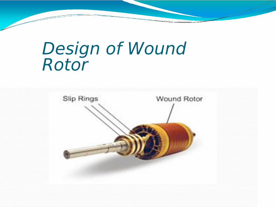
Design of Wound Rotor
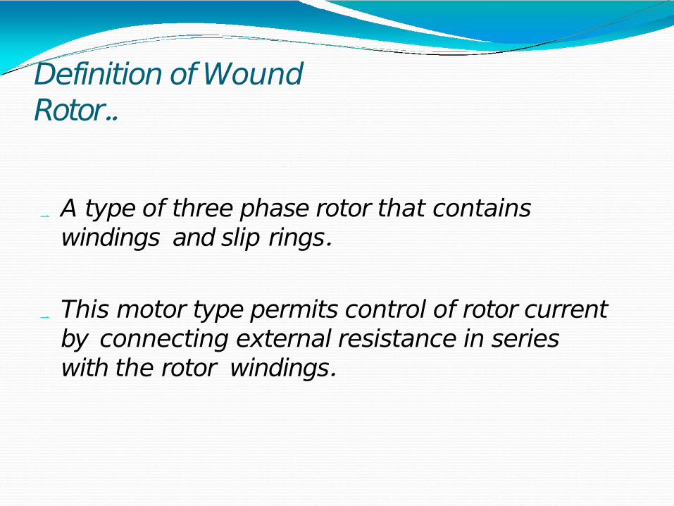
Definition of Wound Rotor..
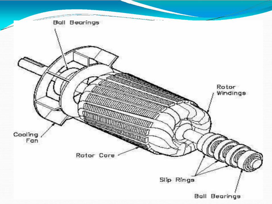
A type of three phase rotor that contains windings and slip rings.
This motor type permits control of rotor current by connecting external resistance in series with the rotor windings.
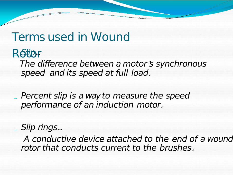
Terms used in Wound Rotor Slip..
The difference between a motor's synchronous speed and its speed at full load.
Percent slip is a way to measure the speed performance of an induction motor.
Slip rings..A conductive device attached to the end of a wound
rotor that conducts current to the brushes.
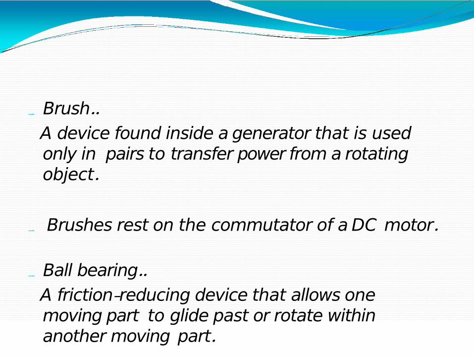
Brush..A device found inside a generator that is used only in pairs to transfer power from a rotating object.
Brushes rest on the commutator of a DC motor.
Ball bearing..A friction-reducing device that allows one moving part to glide past or rotate within another moving part.
Design of wound rotor Basic Requirements.
1.Variable speed 2.High Starting torque
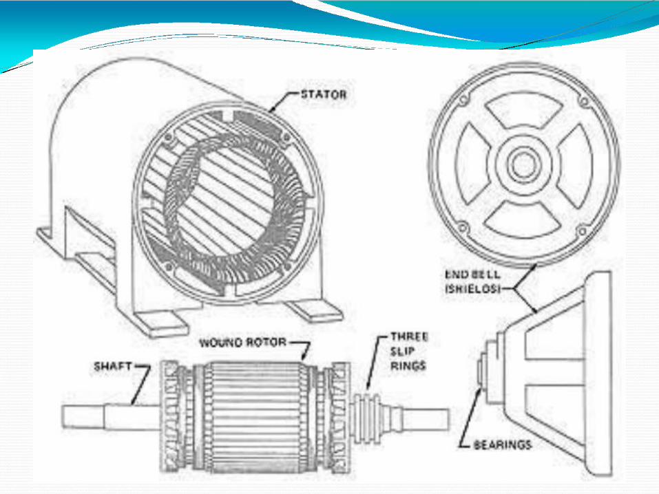
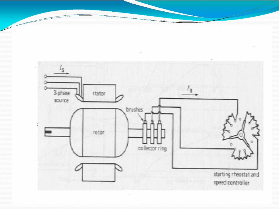
Rotor consists of three phase winding to form same no. of poles in stator .
Rotor winding is connected in star and open ends are connected to 3 slip rings mounted in rotor shaft.
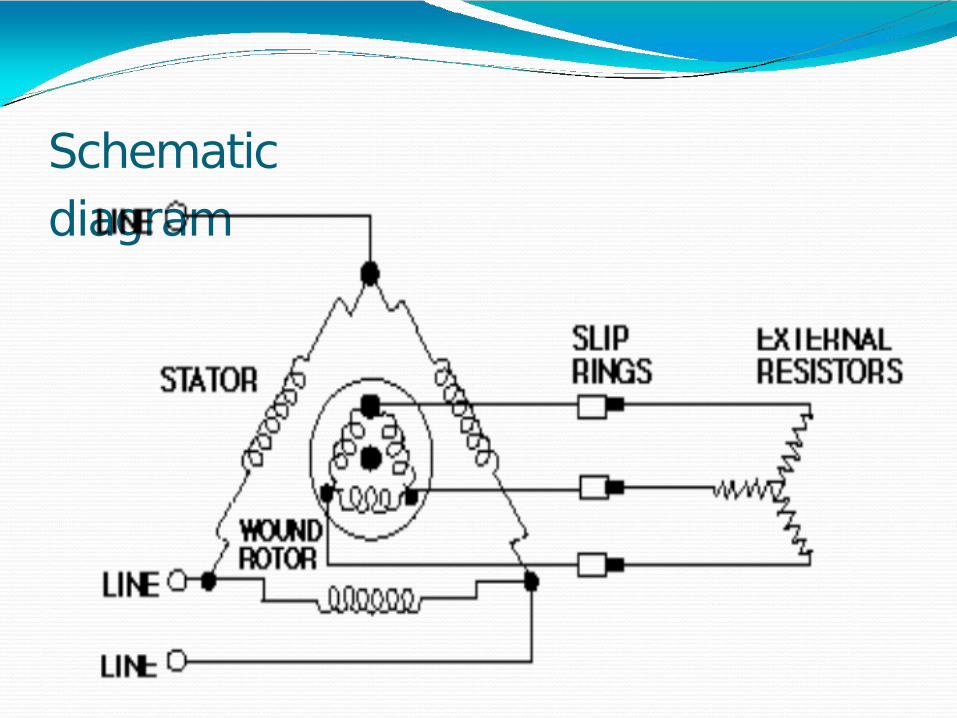
Schematic diagram
Rotor winding are shorted through carbon brushes riding on slip rings.
The existence of series resistances enable user to modify speed characteristics of motor. They are adjusted to control torque and starting speed.
Rotor Resistance Effect on Torque & Speed Placing resistance in series with the rotor windings
not only decreases start current, but also increases the starting torque.
By increasing the rotor resistance from R0 to R1 to R2, the breakdown torque peak is shifted left to zero speed.
3 phase winding
If rotor resistance is increased the slip will increase and hence speed regulation will be poorer and also low efficiency.
Speed of wound rotor motor can be controlled from 50- 100% of rated speed by changing the resistance
Torque peak is much higher than the starting torque available with no rotor resistance (R0).
Slip is proportional to rotor resistance, and pullout torque is proportional to slip. Thus, high torque is produced while starting.
Properties of Wound Rotor Constant speed-service requiring a heavy
starting torque than with a squirrel cage rotor.
Low starting current.
Insertion of high external resistance alters the starting torque to higher value
The running efficiency could be achieved by cutting out external resistance ,when motor picks its speed.
High staring torque and variable speed control
Advantages of Wound Rotor induction motors
The main advantage of a slip ring induction motor is that its speed can be controlled easily.
It has a high starting torque when compared to squirrel cage induction motor. Approximately 200 – 250 % of its full-load torque.
A squirrel cage induction motor takes 600 % to 700 % of the full load current, but a slip ring induction motor takes a very low starting current approximately 250 % to 350 % of the full load current
Disadvantages of wound Rotor Induction Motor
Initial and maintenance cost is more compared to squirrel cage motor because presence of slip rings, brushes, short circuiting devices etc.
Speed regulation is poor when operated with external resistances in rotor circuit.
Efficiency and power factor of slip ring motor is lower compared to squirrel cage induction motor.
Sensitivity to fluctuations in supply voltage
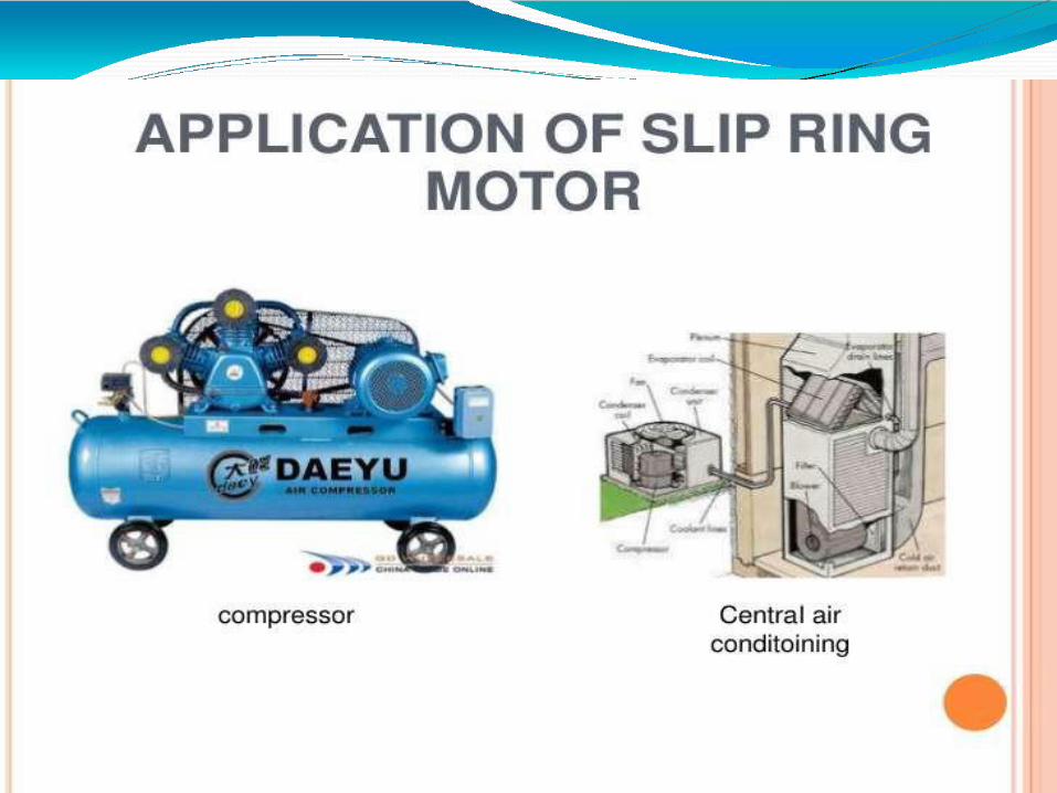
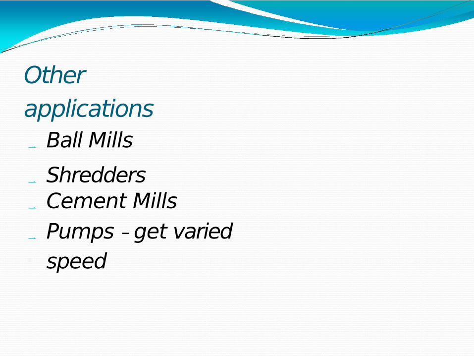
Other applications Ball Mills Shredders Cement Mills Pumps - get varied
speed
The resistance in the rotor circuit is there to increase the slip between the rotor magnetic field and the rotating magnetic field on the stator without increasing the stator current, so providing a fairly primitive variable speed drive from a fixed frequency AC current.The motors are noted for their ruggedness compared to equiva lent DC dr ives , which were the only alternative for variable speed prior to the advent of the electronic variable frequency drives which only became available for regular industrial applications (at high p r i c e s ) i n t h e 1 9 8 0 ’ s .
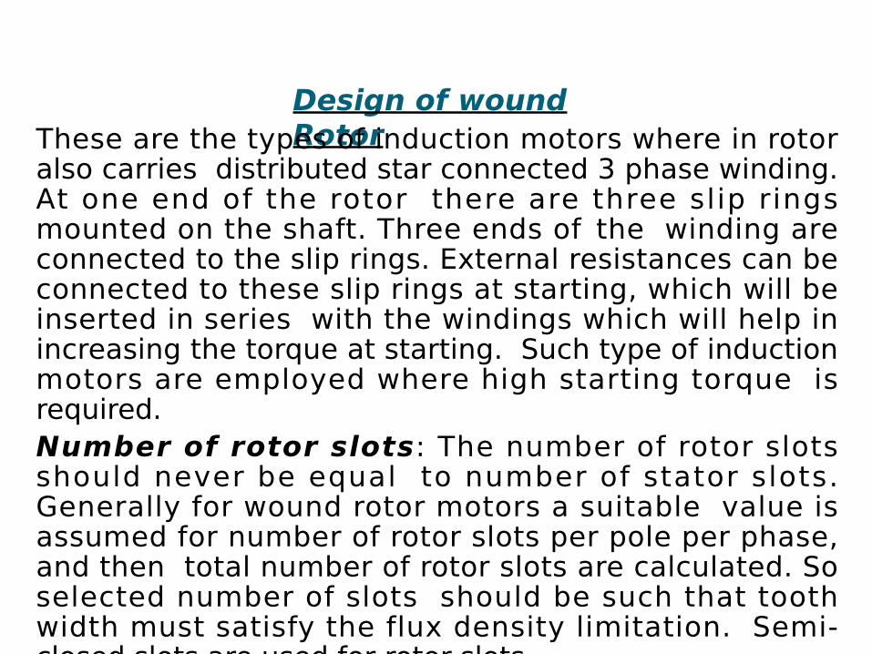
Design of wound RotorThese are the types of induction motors where in rotor
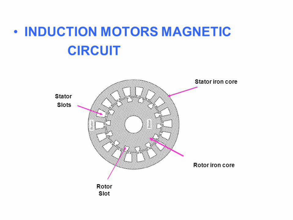
also carries distributed star connected 3 phase winding. At one end of the rotor there are three slip rings mounted on the shaft. Three ends of the winding are connected to the slip rings. External resistances can be connected to these slip rings at starting, which will be inserted in series with the windings which will help in increasing the torque at starting. Such type of induction motors are employed where high starting torque is required.Number of rotor slots: The number of rotor slots should never be equal to number of stator slots. Generally for wound rotor motors a suitable value is assumed for number of rotor slots per pole per phase, and then total number of rotor slots are calculated. So selected number of slots should be such that tooth width must satisfy the flux density limitation. Semi-closed slots are used for rotor slots.
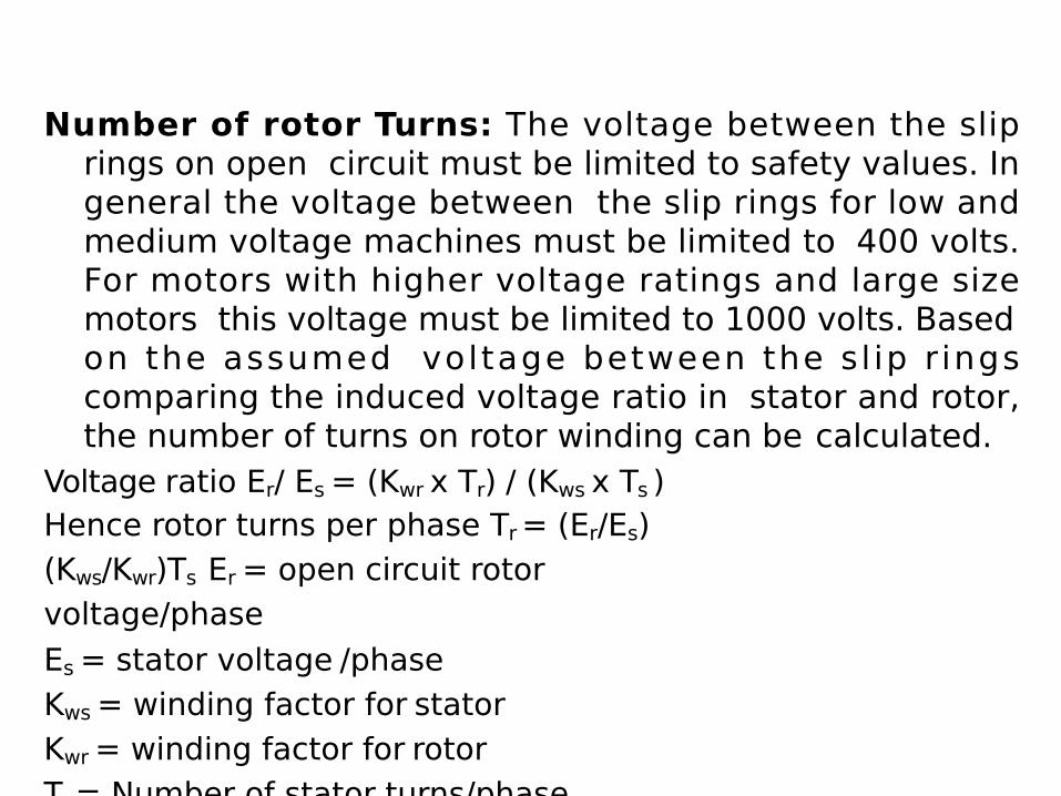
Number of rotor Turns: The voltage between the slip rings on open circuit must be limited to safety values. In general the voltage between the slip rings for low and medium voltage machines must be limited to 400 volts. For motors with higher voltage ratings and large size motors this voltage must be limited to 1000 volts. Based on the assumed voltage between the sl ip r ings comparing the induced voltage ratio in stator and rotor, the number of turns on rotor winding can be calculated.
Voltage ratio Er/ Es = (Kwr x Tr) / (Kws x Ts )Hence rotor turns per phase Tr = (Er/Es) (Kws/Kwr)Ts Er = open circuit rotor voltage/phaseEs = stator voltage /phaseKws = winding factor for statorKwr = winding factor for rotorTs = Number of stator turns/phase
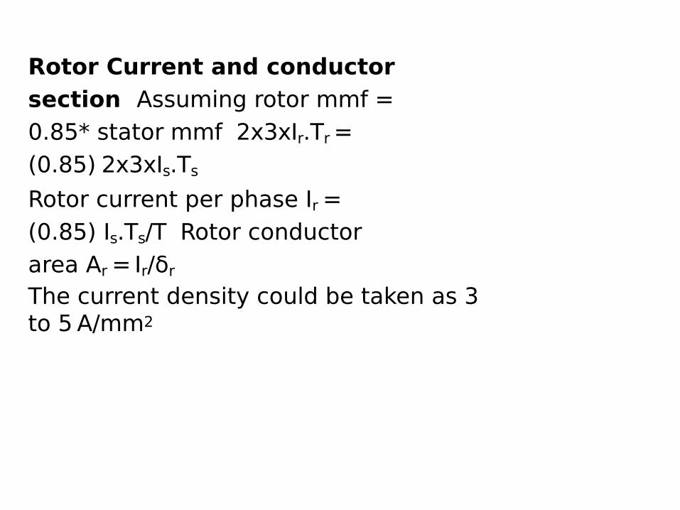
Rotor Current and conductor section Assuming rotor mmf = 0.85* stator mmf 2x3xIr.Tr = (0.85) 2x3xIs.TsRotor current per phase Ir = (0.85) Is.Ts/T Rotor conductor area Ar = Ir/δrThe current density could be taken as 3 to 5 A/mm2
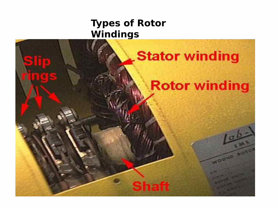
Types of Rotor Windings
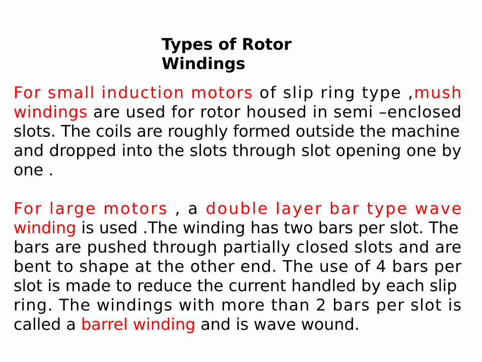
Types of Rotor Windings
For small induction motors of slip ring type ,mush windings are used for rotor housed in semi –enclosed slots. The coils are roughly formed outside the machine and dropped into the slots through slot opening one by one .
For large motors , a double layer bar type wave winding is used .The winding has two bars per slot. The bars are pushed through partially closed slots and are bent to shape at the other end. The use of 4 bars per slot is made to reduce the current handled by each slip ring. The windings with more than 2 bars per slot is called a barrel winding and is wave wound.
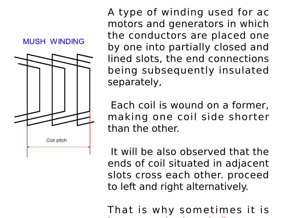
A type of winding used for ac motors and generators in which the conductors are placed one by one into partially closed and lined slots, the end connections being subsequently insulated separately,
Each coil is wound on a former, making one coil side shorter than the other.
It will be also observed that the ends of coil situated in adjacent slots cross each other. proceed to left and right alternatively.
That is why sometimes i t is known as a basket winding.
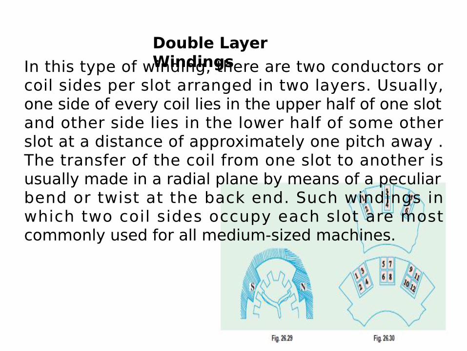
Double Layer Windings In this type of winding, there are two conductors or
coil sides per slot arranged in two layers. Usually, one side of every coil lies in the upper half of one slot and other side lies in the lower half of some other slot at a distance of approximately one pitch away . The transfer of the coil from one slot to another is usually made in a radial plane by means of a peculiar bend or twist at the back end. Such windings in which two coil sides occupy each slot are most commonly used for all medium-sized machines.
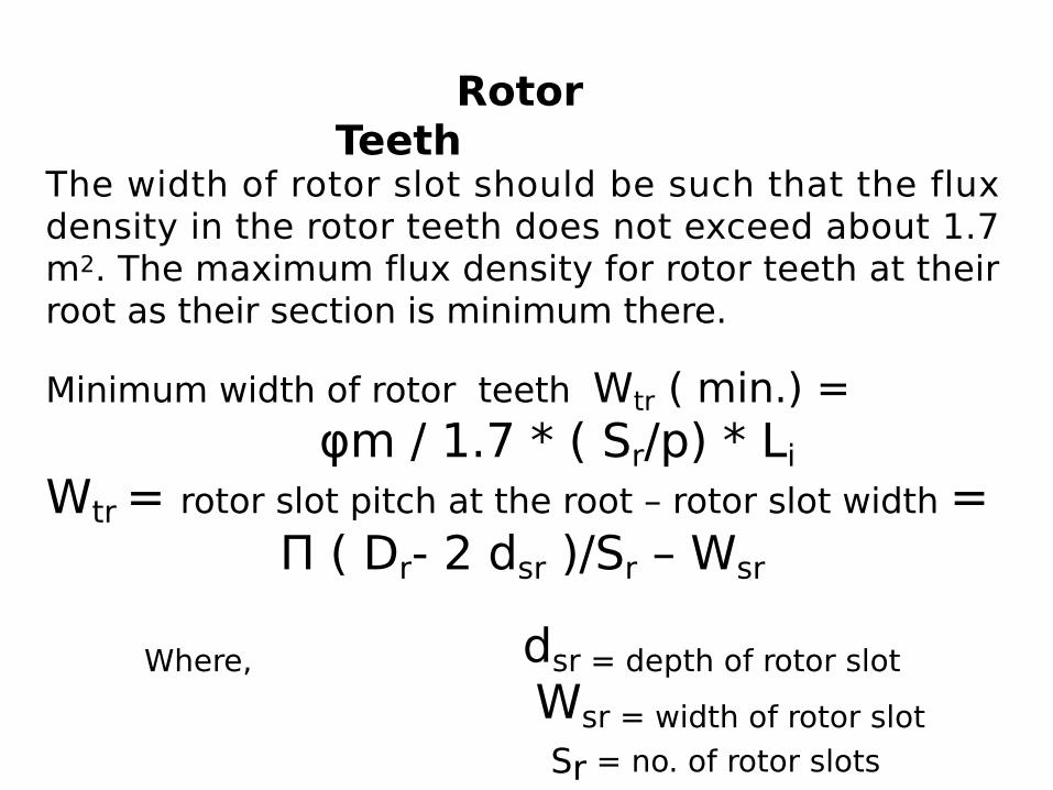
Rotor Teeth
The width of rotor slot should be such that the flux density in the rotor teeth does not exceed about 1.7 m2. The maximum flux density for rotor teeth at their root as their section is minimum there.
Minimum width of rotor teeth Wtr ( min.) = φm / 1.7 * ( Sr/p) * LiWtr = rotor slot pitch at the root – rotor slot width =
Π ( Dr- 2 dsr )/Sr – Wsr
Where, dsr = depth of rotor slot Wsr = width of rotor slot
Sr = no. of rotor slots
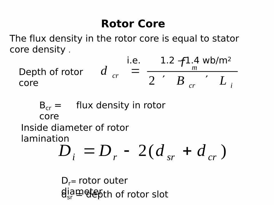
Rotor Core
icr
mcr LB
d´´
=2
fDepth of rotor core
Bcr = flux density in rotor core
)(2 crsrri ddDD +-=Inside diameter of rotor lamination
dsr = depth of rotor slot Dr= rotor outer diameter
The flux density in the rotor core is equal to stator core density . i.e. 1.2 – 1.4 wb/m2
Estimation of operating Characteristics
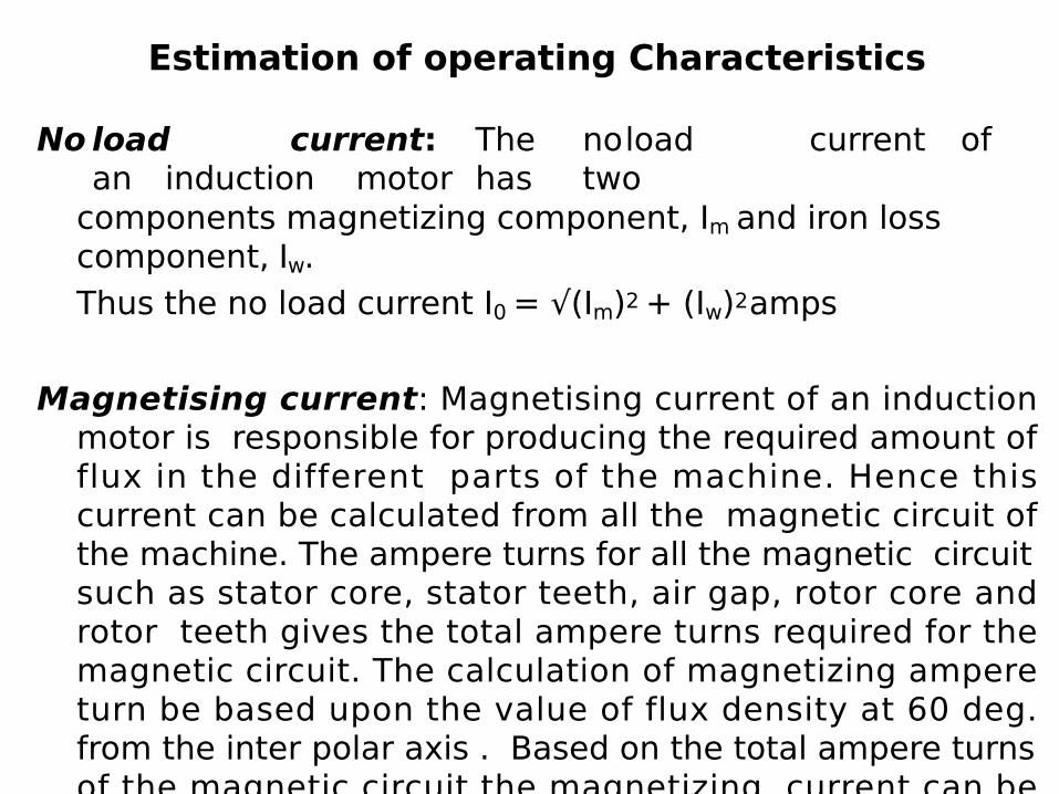
No load current: The noload current ofan induction motor has two
components magnetizing component, Im and iron loss component, Iw.Thus the no load current I0 = √(Im)2 + (Iw)2 amps
Magnetising current: Magnetising current of an induction motor is responsible for producing the required amount of flux in the different parts of the machine. Hence this current can be calculated from all the magnetic circuit of the machine. The ampere turns for all the magnetic circuit such as stator core, stator teeth, air gap, rotor core and rotor teeth gives the total ampere turns required for the magnetic circuit. The calculation of magnetizing ampere turn be based upon the value of flux density at 60 deg. from the inter polar axis . Based on the total ampere turns of the magnetic circuit the magnetizing current can be calculated .
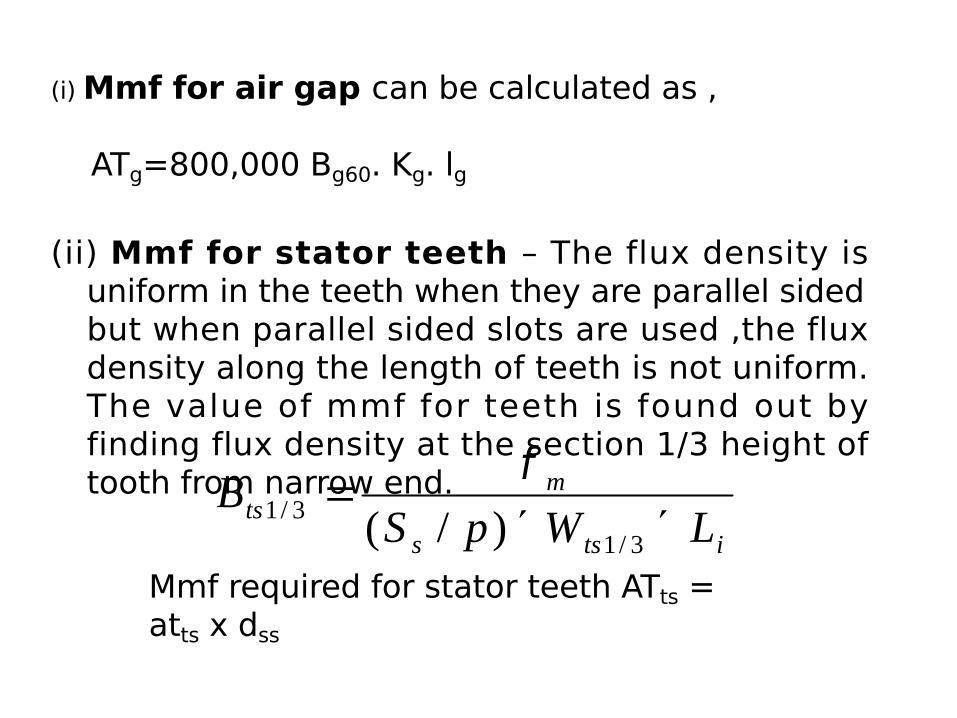
(i) Mmf for air gap can be calculated as ,
ATg=800,000 Bg60. Kg. lg
(ii) Mmf for stator teeth – The flux density is uniform in the teeth when they are parallel sided but when parallel sided slots are used ,the flux density along the length of teeth is not uniform. The value of mmf for teeth is found out by finding flux density at the section 1/3 height of tooth from narrow end.
itss
mts LWpSB
´´=
3/13/1 )/(
f
Mmf required for stator teeth ATts = atts x dss
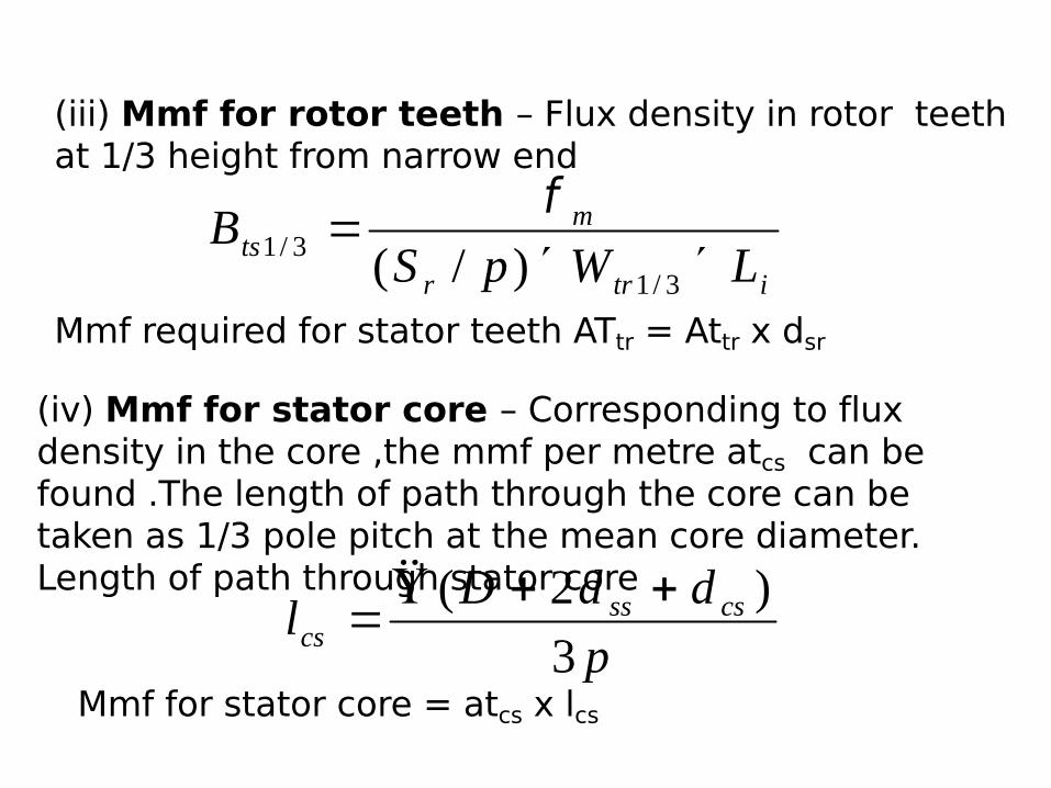
(iii) Mmf for rotor teeth – Flux density in rotor teeth at 1/3 height from narrow end
itrr
mts LWpSB
´´=
3/13/1 )/(
f
Mmf required for stator teeth ATtr = Attr x dsr
(iv) Mmf for stator core – Corresponding to flux density in the core ,the mmf per metre atcs can be found .The length of path through the core can be taken as 1/3 pole pitch at the mean core diameter. Length of path through stator core
pddDl csss
cs 3)2( ++P
=
Mmf for stator core = atcs x lcs
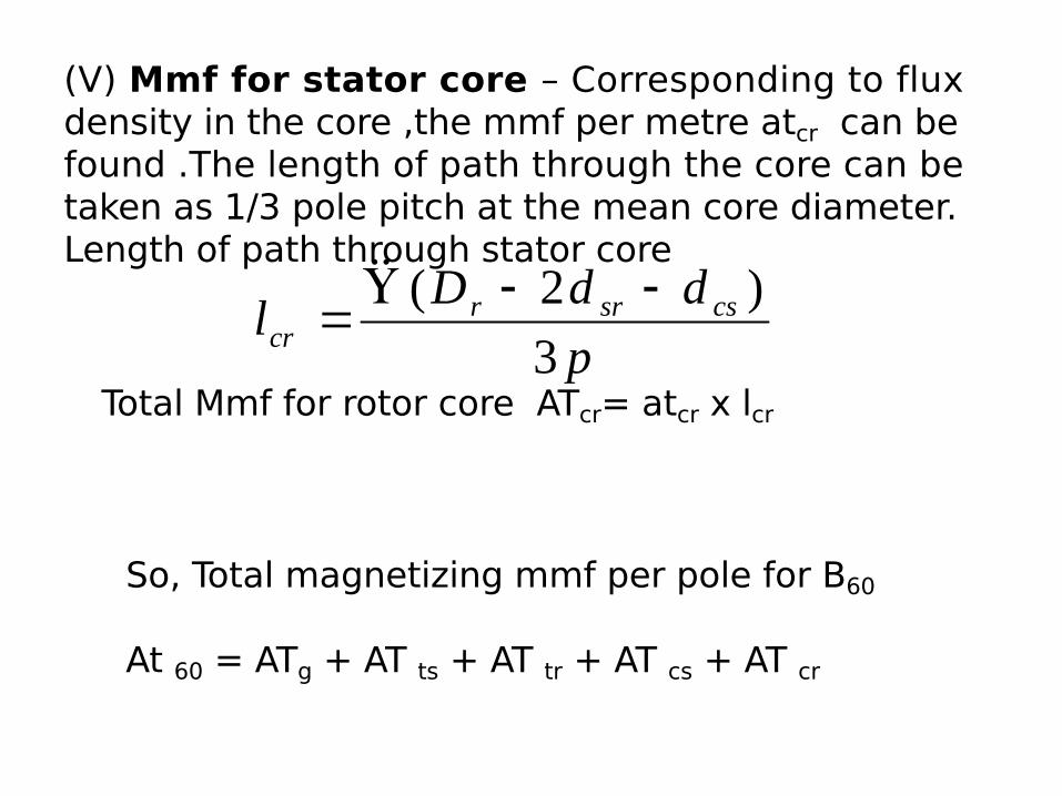
(V) Mmf for stator core – Corresponding to flux density in the core ,the mmf per metre atcr can be found .The length of path through the core can be taken as 1/3 pole pitch at the mean core diameter. Length of path through stator core
pddDl cssrr
cr 3)2( --P
=
Total Mmf for rotor core ATcr= atcr x lcr
So, Total magnetizing mmf per pole for B60
At 60 = ATg + AT ts + AT tr + AT cs + AT cr
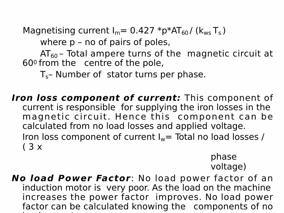
Magnetising current Im= 0.427 *p*AT60 / (kws Ts )where p – no of pairs of poles, AT60 – Total ampere turns of the magnetic circuit at
600 from the centre of the pole,Ts– Number of stator turns per phase.
Iron loss component of current: This component of current is responsible for supplying the iron losses in the magnetic circuit . Hence this component can be calculated from no load losses and applied voltage.Iron loss component of current Iw= Total no load losses / ( 3 x
phase voltage)
No load Power Factor: No load power factor of an induction motor is very poor. As the load on the machine increases the power factor improves. No load power factor can be calculated knowing the components of no load current.
No load power factor cosφ = Iw / I0
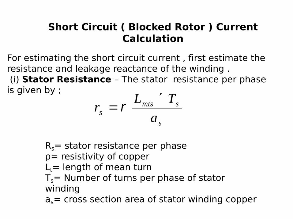
Short Circuit ( Blocked Rotor ) Current Calculation
For estimating the short circuit current , first estimate the resistance and leakage reactance of the winding . (i) Stator Resistance – The stator resistance per phase is given by ;
s
smtss a
TLr ´= r
Rs= stator resistance per phase ρ= resistivity of copperLt= length of mean turnTs= Number of turns per phase of stator winding as= cross section area of stator winding copper
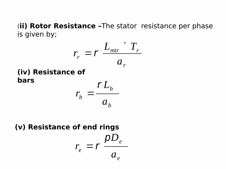
(ii) Rotor Resistance –The stator resistance per phase is given by;
r
rmtrr a
TLr ´= r
(iv) Resistance of bars
b
bb a
Lr
r=
(v) Resistance of end rings
e
ee a
Dr
pr=
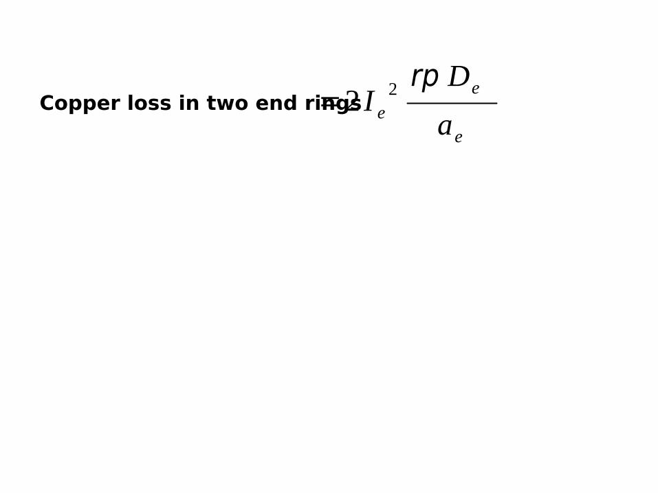
Copper loss in two end rings e
ee a
DI
rp22=
Leakage Reactance in Induction Motor
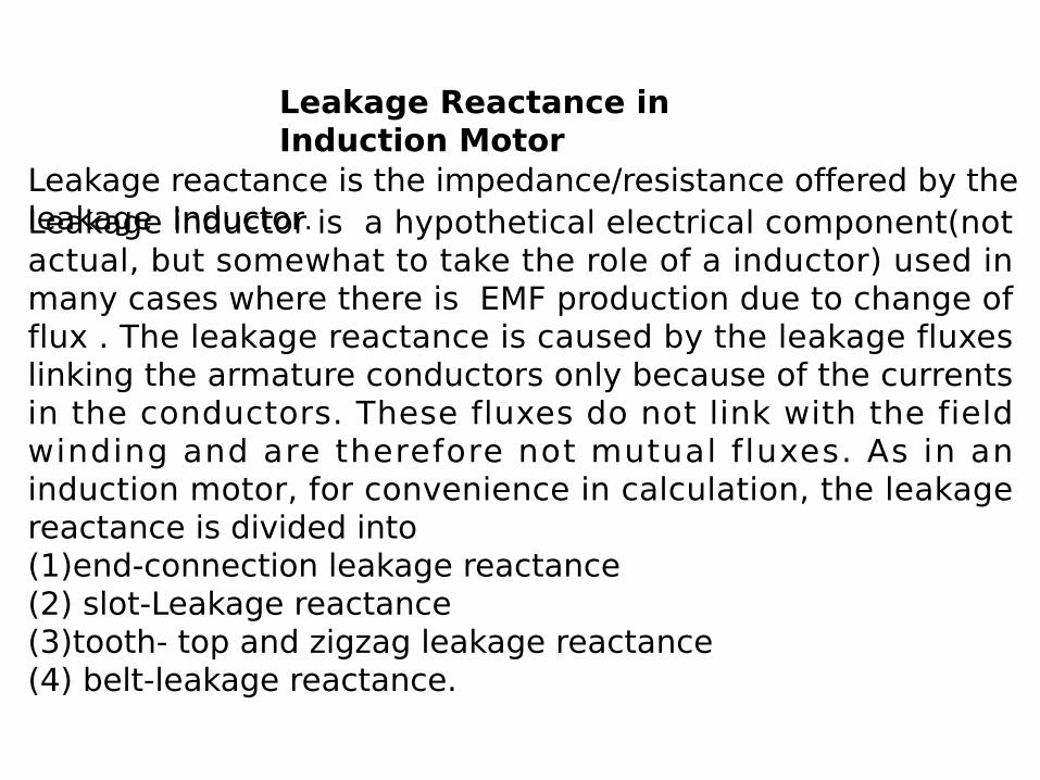
Leakage reactance is the impedance/resistance offered by the leakage Inductor.Leakage inductor is a hypothetical electrical component(not actual, but somewhat to take the role of a inductor) used in many cases where there is EMF production due to change of flux . The leakage reactance is caused by the leakage fluxes linking the armature conductors only because of the currents in the conductors. These fluxes do not link with the field winding and are therefore not mutual fluxes. As in an induction motor, for convenience in calculation, the leakage reactance is divided into (1)end-connection leakage reactance(2) slot-Leakage reactance (3)tooth- top and zigzag leakage reactance(4) belt-leakage reactance.
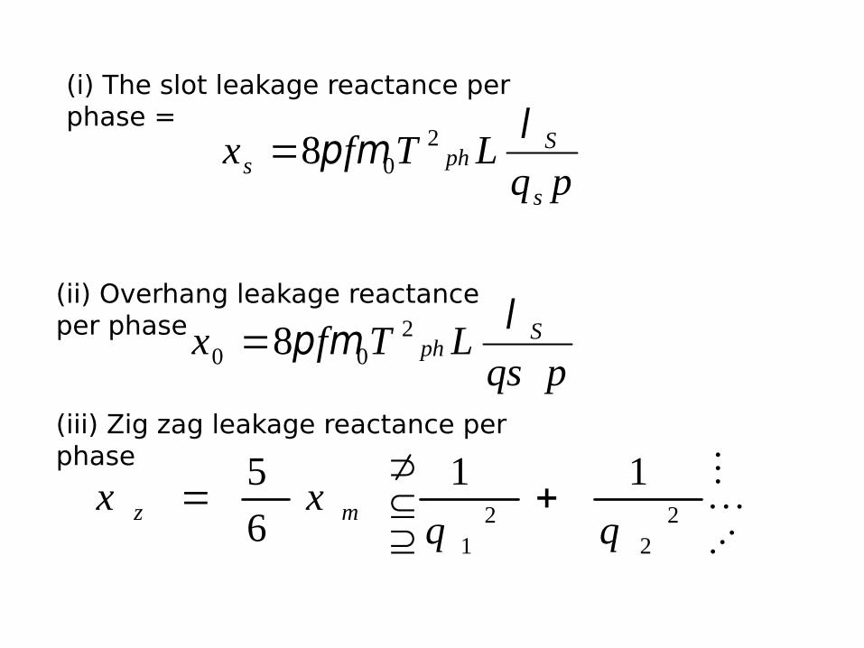
(i) The slot leakage reactance per phase =
pqLTfx
s
Sphs
lmp 208=
(ii) Overhang leakage reactance per phase
pqsLTfx S
phlmp 2
00 8=
(iii) Zig zag leakage reactance per phase
úû
ùêë
é+= 2
22
1
1165
qqxx mz
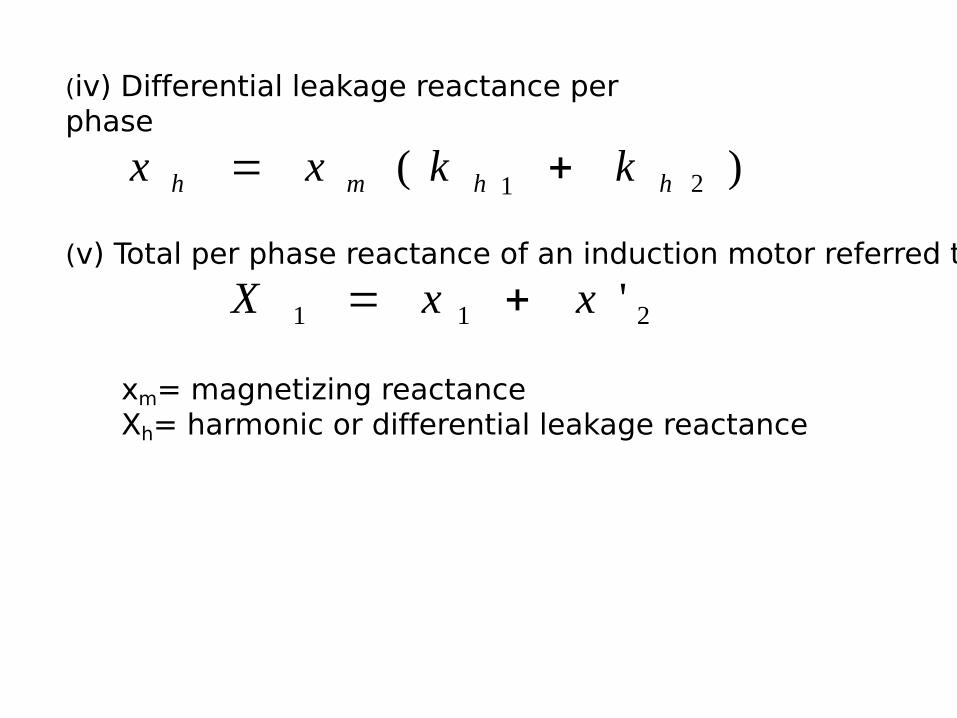
(iv) Differential leakage reactance per phase
)( 21 hhmh kkxx +=
(v) Total per phase reactance of an induction motor referred to stator is 211 'xxX +=
xm= magnetizing reactanceXh= harmonic or differential leakage reactance
Circle Diagram of Induction Motor
The “CIRCLE DIAGRAM” means that it is figure or curve which is drawn has a circular shape. As we know, the diagrammatic representation is easier to understand a n d re m e m b e r c o m p a re d t o t h e o re t i c a l a n d mathematical descriptions. Actually, we do not have that much time or patience to go through the writings so we prefer diagrammatic representation. Also, it is very easy to remember the things which are shown in picture. As we know, “A PICTURE IS WORTH 1000 WORDS”. This also holds good here and we are to draw circle diagram in order to compute various parameters rather than doing it mathematically.
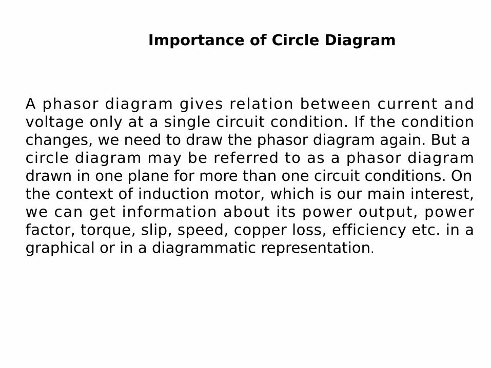
A phasor diagram gives relation between current and voltage only at a single circuit condition. If the condition changes, we need to draw the phasor diagram again. But a circle diagram may be referred to as a phasor diagram drawn in one plane for more than one circuit conditions. On the context of induction motor, which is our main interest, we can get information about its power output, power factor, torque, slip, speed, copper loss, efficiency etc. in a graphical or in a diagrammatic representation.
Importance of Circle Diagram
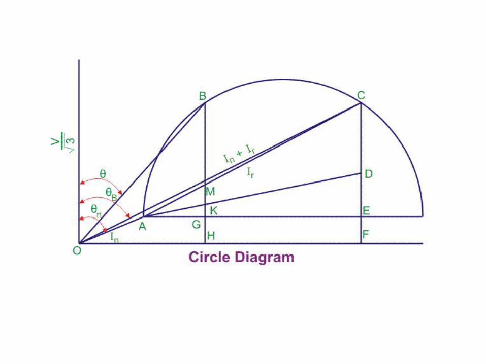
STEPS:-•The no load current and the no load angle calculated from no load test is plotted. This is shown by the line OA, where Ɵ0 is the no load power factor angle. •The short circuit current and the angle obtained from block rotor test is plotted. This is shown by the line OC and the angle is shown by ƟB. The right bisector of the line AC is drawn which bisects the line and it is extended to cut in the line AE which gives us the centre. •The stator current is calculated from the equivalent circuit of the induction motor which we get from the two tests. That current is plotted in the circle diagram according to the scale with touching origin and a point in the circle diagram which is shown by B.•The line AC is called the power line. By using the scale for power conversion that we have taken in the circle diagram, we can get the output power if we move vertically above the line AC to the periphery of the circle. The output power is given by the line MB. •The total copper loss is given by the line GM. •For drawing the torque line, the total copper loss should be separated to both the rotor copper loss and stator copper loss. The line DE gives the stator copper loss and the line CD gives the rotor copper loss. In this way, the point E is selected. •The line AD is known as torque line which gives the torque developed by induction motor.
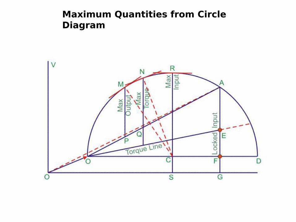
Maximum Quantities from Circle Diagram
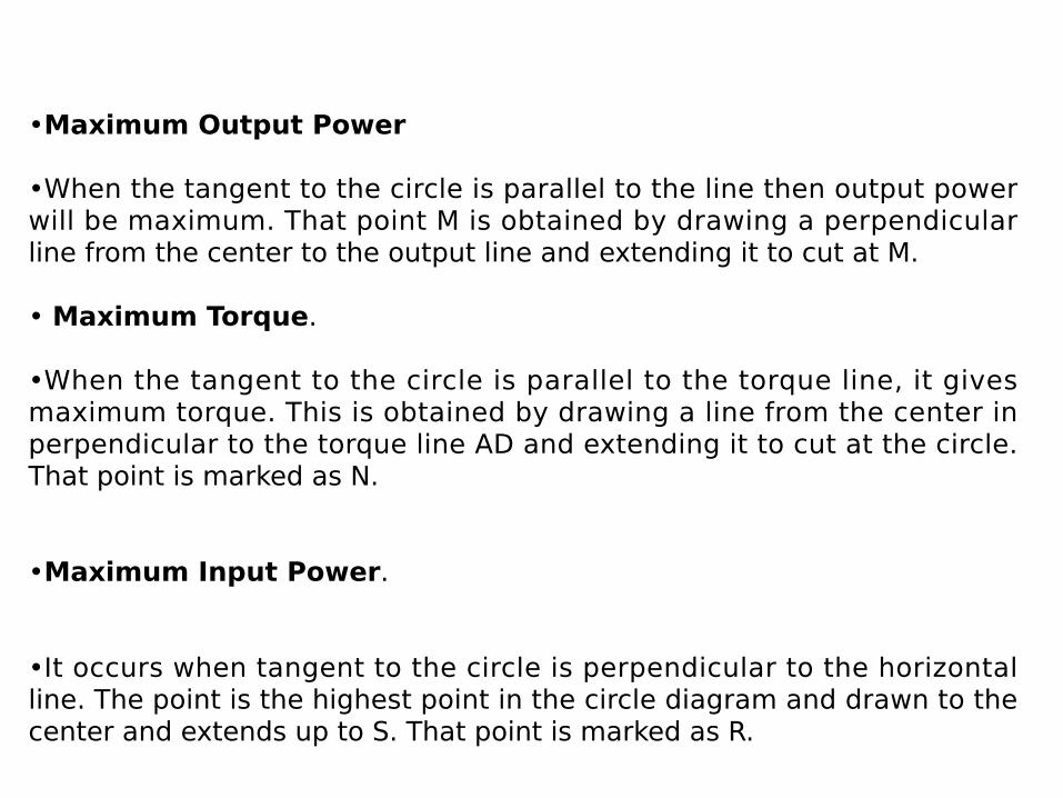
•Maximum Output Power
•When the tangent to the circle is parallel to the line then output power will be maximum. That point M is obtained by drawing a perpendicular line from the center to the output line and extending it to cut at M.
• Maximum Torque.
•When the tangent to the circle is parallel to the torque line, it gives maximum torque. This is obtained by drawing a line from the center in perpendicular to the torque line AD and extending it to cut at the circle. That point is marked as N.
•Maximum Input Power.
•It occurs when tangent to the circle is perpendicular to the horizontal line. The point is the highest point in the circle diagram and drawn to the center and extends up to S. That point is marked as R.
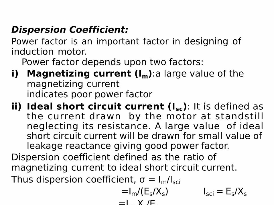
Dispersion Coefficient:Power factor is an important factor in designing of induction motor.
Power factor depends upon two factors:i) Magnetizing current (Im):a large value of the
magnetizing currentindicates poor power factor
ii) Ideal short circuit current (Isc): It is defined as the current drawn by the motor at standstill neglecting its resistance. A large value of ideal short circuit current will be drawn for small value of leakage reactance giving good power factor.
Dispersion coefficient defined as the ratio of magnetizing current to ideal short circuit current.Thus dispersion coefficient, σ = Im/Isci
=Im/(Es/Xs) Isci = Es/Xs=Im.Xs/Es
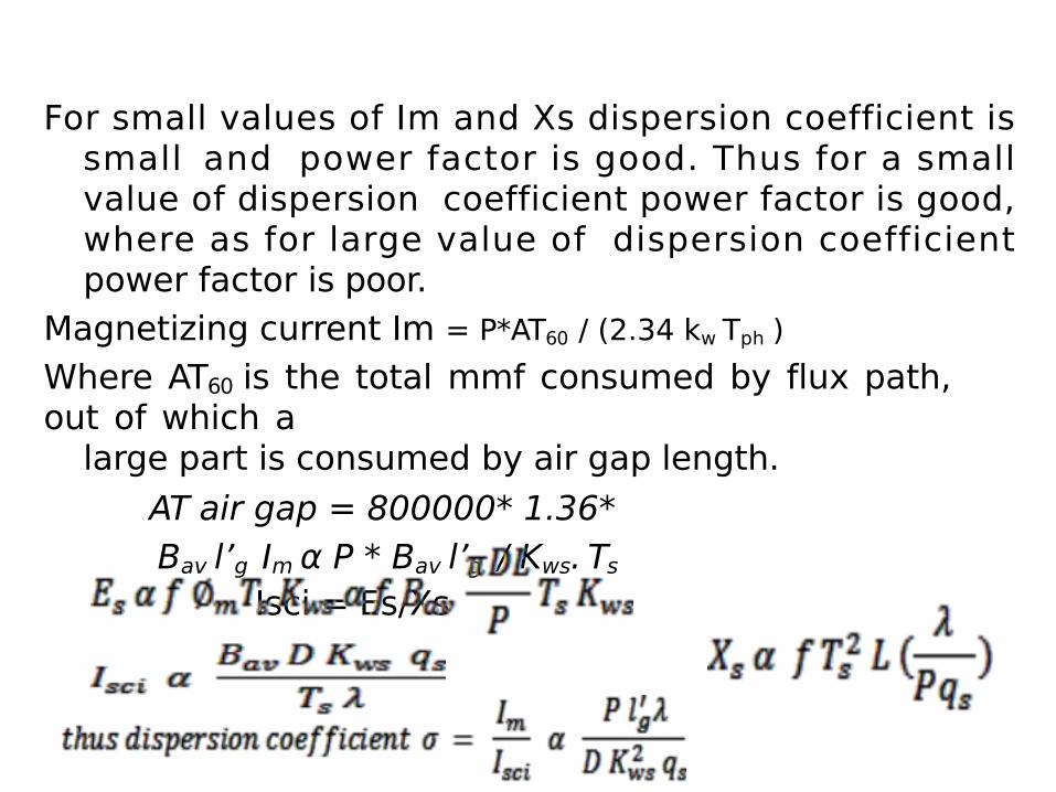
For small values of Im and Xs dispersion coefficient is small and power factor is good. Thus for a small value of dispersion coefficient power factor is good, where as for large value of dispersion coefficient power factor is poor.
Magnetizing current Im = P*AT60 / (2.34 kw Tph )Where AT60 is the total mmf consumed by flux path, out of which a
large part is consumed by air gap length.AT air gap = 800000* 1.36* Bav l’g Im α P * Bav l’g / Kws. Ts
Isci = Es/Xs
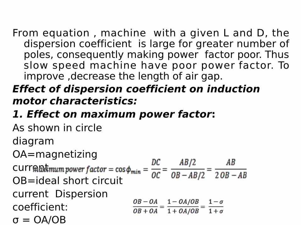
From equation , machine with a given L and D, the dispersion coefficient is large for greater number of poles, consequently making power factor poor. Thus slow speed machine have poor power factor. To improve ,decrease the length of air gap.
Effect of dispersion coefficient on induction motor characteristics:1. Effect on maximum power factor:As shown in circle diagram OA=magnetizing currentOB=ideal short circuit current Dispersion coefficient:σ = OA/OB
For maximum power factor OD is tangent to the circle and∟ODC =90o
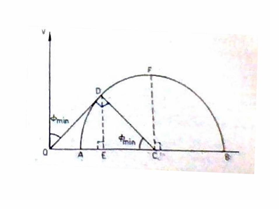
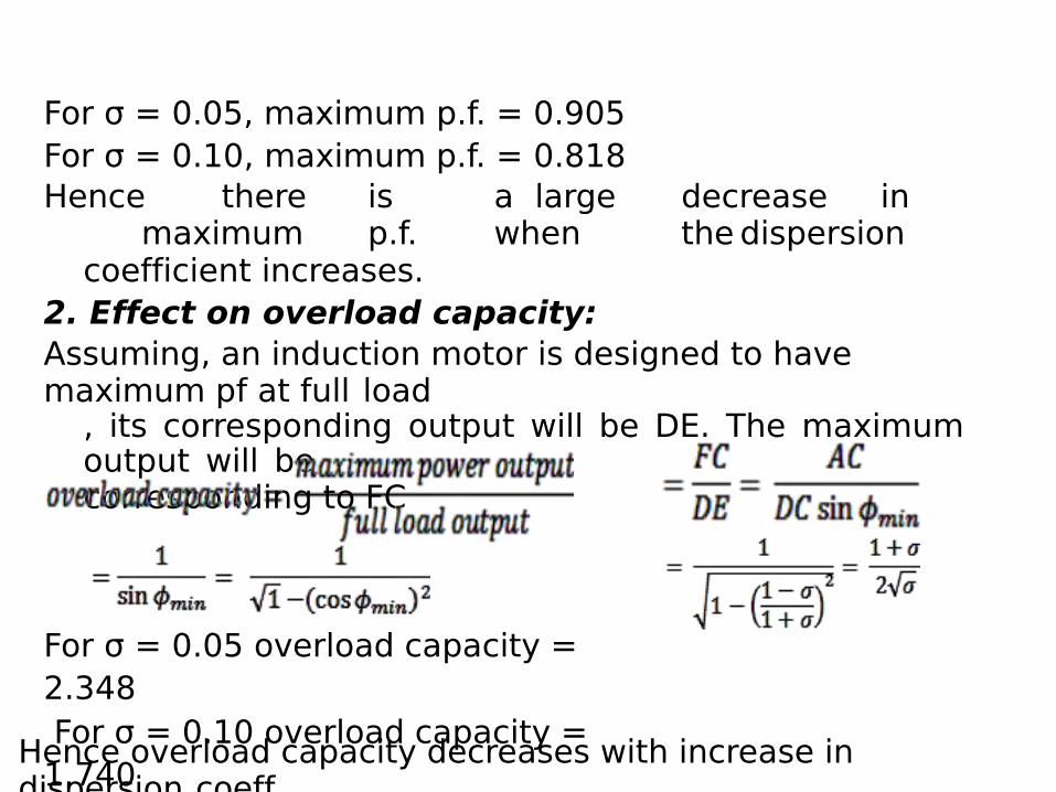
For σ = 0.05, maximum p.f. = 0.905For σ = 0.10, maximum p.f. = 0.818Hence there is a large decrease in
maximum p.f. when the dispersioncoefficient increases.
2. Effect on overload capacity:Assuming, an induction motor is designed to have maximum pf at full load
, its corresponding output will be DE. The maximum output will becorresponding to FC
For σ = 0.05 overload capacity = 2.348 For σ = 0.10 overload capacity = 1.740Hence overload capacity decreases with increase in
dispersion coeff.