Embed Size (px)
Citation preview
565 | International Journal of Computer Systems, ISSN-(2394-1065), Vol. 03, Issue 08, August, 2016
International Journal of Computer Systems (ISSN: 2394-1065), Volume 03– Issue 08, August, 2016
Available at http://www.ijcsonline.com/
Design of Ultra-wide Band Reconfigurable Micro Strip Antennas for Cognitive
Radio Applications
K. Naga Prasanna, Dr. P. Nageswararao, Y. Anusha
Department of ECE, G. Pullaiah College of Engineering and Technology, India
Abstract
This paper presents a new antenna schemes for cognitive radio applications. The cognitive radio consists of ultra-wide
band (UWB) sensing antenna and the frequency reconfigurable communicating antenna both are incorporated into the
same substrate. Two different types of antenna geometrics are proposed in this paper. The first one is communicating E-
shaped patch antenna whereas the second one is the ring shaped sensing antenna with inverted C-shaped communicating
antenna. In both antennas, Reconfigurabilty is achieved by controlling the PIN diodes in the antenna structures. IE3D
simulation software is used to design and simulate the antennas.
Keywords: Cognitive radio, coplanar wave guide, E-shaped patch, frequency reconfigurable, ring-shaped sensing
antenna, ultra-wide band.
I. INTRODUCTION
Antennas have become a necessary and critical component of all personal electronic devices, microwave and satellite communication systems. In many of these systems, there is a requirement to perform a multitude of functions across several frequency bands and operating band widths, especially in the area of cognitive radio. The communication link between two antennas typically suffers from multipath, interference, and fading. These various phenomena can restrict the performance of present day wireless communication systems [1]. The improvements involving antennas the including the usage of antenna diversity in order to overcome the limitations imposed on the system performance with a single receiving antenna. Reconfigurable antenna is used to enhance a single antenna by the additional functionalities.
Re-configurability, when used in the context of antennas, is the capacity to change an individual radiator‟s fundamental operating characteristics through electrical, mechanical, or other means. The reconfiguration of such an antenna is achieved through an intentional redistribution of the currents or, equivalently, the electromagnetic fields of the antenna‟s effective aperture, resulting in reversible changes in the antenna impedance and radiation properties. Many techniques can be used to achieve the reconfiguration of an antenna. Most of these techniques resort to switches, diodes or capacitors. Other techniques resort to mechanical alterations like a rotation or bending of a certain antenna part. The frequency band is typically assumed to be set, and the main goal is to improve the system performance for the given band by exploiting spatial features of the wireless environment. Another technique that is currently gaining momentum is the use of software defined radio in the concept of dynamic spectrum access, also known as cognitive radio. Cognitive radio is a form of wireless communication in which transceiver can intelligently detect which communication channels are in use and which are not, and instantly move in to vacant
channels while avoiding occupied ones. Generally, cognitive radio refers to the full communication system architectures which are able to sense the environment for licensed (primary) users and utilize available spectrum which is not being used currently. Cognitive radio takes advantage of frequency and time aspects of wireless environment at any given location, time and direction frequency spectrum may not be fully utilized. A reconfigurable slot antenna for cognitive radio applications was proposed by J.R. Kelly and P.S. Hall [2] where the Reconfigurabilty is achieved by inserting slots in antenna structure instead of switches. Thus, enabling dynamic spectrum access offers many benefits to wireless systems including the opportunity to combat fading and possibly improve channel capacity through wider band width.
Cognitive radio is an intelligent wireless communication system which can perceive their environment. Cognitive radio improves the spectrum utilization and hence when there is failure or congestion of certain existing technology at times of emergency and disaster [3]. Cognitive radio network can be deployed in Ad-hoc and mesh architecture. The antenna requirements for cognitive radio system can also depend upon the network architecture.
Ad-hoc networks are composed of cognitive radio devices that are self-organizing and can be diploid of without any present infrastructure. The basic components of cognitive radio networks are Mobile station (MS), Base station (BS)and Core networks, if a Mobile station with cognitive capabilities recognize that there are some other capital MS nearby they can set up a link through certain communication protocol and thus form an ad hoc network.
As an alternative to multi band antennas, Frequency Reconfigurable Antennas are used. Reconfigurable antenna provides attractive potentials solutions to solve the challenging antenna problems related to cognitive radio systems using the ability to switch patterns, frequency and polarization. The reconfiguration of an antenna is achieved
K. Naga Prasanna et al Design of Ultra-wide Band Reconfigurable Micro Strip Antennas for Cognitive Radio Applications
566 | International Journal of Computer Systems, ISSN-(2394-1065), Vol. 03, Issue 08, August, 2016
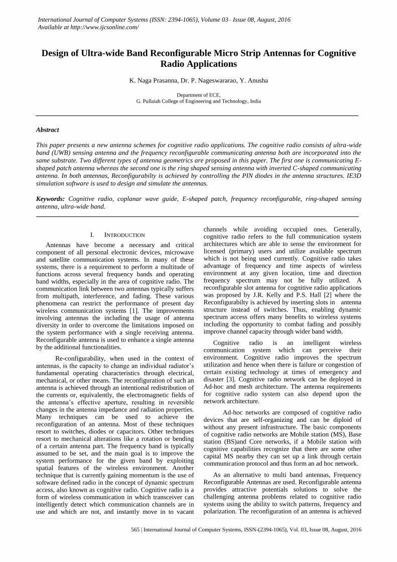
through an intentional redistribution of the currents or, equivalently, the electromagnetic fields of the antenna‟s effective aperture, resulting in reversible changes in the antenna impedance and radiation properties. These antennas exhibit different forms of re configurability. In most cases, electrical devices, such as varactor and PIN diodes, or mechanical switches have been incorporated in the antenna prototypes [4], [5]. Reconfigurabilty can be grouped in to three categories :
Fig1. Ad hoc architecture with preexisting infrastructure
- Reconfigurable resonance frequency antennas
- Reconfigurable radiation pattern antennas
- Reconfigurable polarization antennas
In this paper, a novel frequency reconfigurable E-shaped patch antenna design is presented as a new wide-band patch antenna for possible use in cognitive radio systems. This design could be used in wireless applications such as Laptops, Wi-Fi, Bluetooth, and ZigBee etc. E – Shaped patched design offers a simple single layer single feed structure that is straight forward to manufacture. It provides the accessibility by using the slots for the bias lines to control the switches. A reconfigurable dual-band antenna for wireless applications with very wide range tenability has been proposed by N. Behdad [6]. A reconfigurable patch antenna for satellite and terrestrial application has been reported [7].
This paper is divided into the fallowing sections. In section 2 the two reconfigurable structures are presented and in section 3 simulated results of two structures that are detailed in section 2 finally we concluded in section 4 by summarising the results presented in this work.
II. ULTRA-WIDE BAND RECONFIGURABLE ANTENNA
DESIGNS
Reconfigurable multiband antennas are attractive in case of many applications where it is desirable to have a single antenna that dynamically alters its characteristics to multiple frequency bands. The most common method to achieve the Reconfigurability is incorporating the switches in the antenna design.
This paper proposes a two different antenna designs for CR applications. The first one is communicating E-shaped patch antenna whereas the second one is the ring shaped sensing antenna with inverted C-shaped
communicating antenna. In both antennas, Reconfigurabilty is achieved by controlling the PIN diodes in the antenna structures.
2.1 E-Shaped Patch Antenna Design
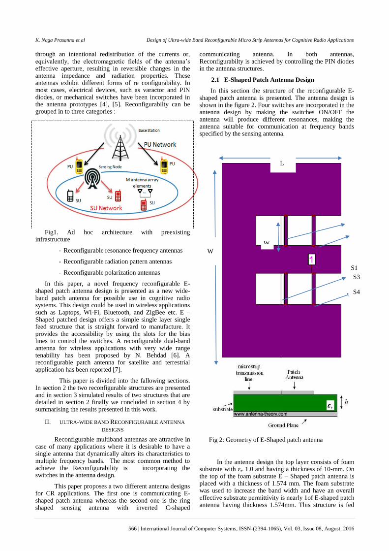
In this section the structure of the reconfigurable E-shaped patch antenna is presented. The antenna design is shown in the figure 2. Four switches are incorporated in the antenna design by making the switches ON/OFF the antenna will produce different resonances, making the antenna suitable for communication at frequency bands specified by the sensing antenna.
Fig 2: Geometry of E-Shaped patch antenna
In the antenna design the top layer consists of foam substrate with ɛrᵙ 1.0 and having a thickness of 10-mm. On the top of the foam substrate E – Shaped patch antenna is placed with a thickness of 1.574 mm. The foam substrate was used to increase the band width and have an overall effective substrate permittivity is nearly 1of E-shaped patch antenna having thickness 1.574mm. This structure is fed
L
W
W
s
S1
S2 S3
S4
K. Naga Prasanna et al Design of Ultra-wide Band Reconfigurable Micro Strip Antennas for Cognitive Radio Applications
567 | International Journal of Computer Systems, ISSN-(2394-1065), Vol. 03, Issue 08, August, 2016
via coaxial cable and has a partial ground of dimensions 44.1×92.5 in the bottom layer. It is printed on a Rogers Duroid 5800 substrate with ɛr= 2.2. The Duroid layer was taken to allow the antenna topology to be etched on to the substrate which is used to provide satisfactory fabrication accuracy.
In fig 2, L is the length of the patch, W is the width of the patch. Ls is the length of the slot. Ws is the width of the slot. Ps is the position of the slots; x is the position of the feed. Four switches are incorporated between the two slots of the E-Shaped patch antenna namely S1, S2, S3 and S4 shown in the figure 2. In order to obtain the frequency and polarization diversity the four switches are made ON/OFF in 16 different modes shown in the Table I.
Table I: Sixteen States of Switches
Two simulations are needed to evaluate the given set of
parameters. One simulation out puts the OFF state characteristics and the other one output the ON state characteristics. The main objective for this antenna design is to obtain good impedance matching. The dimensions of the E-shaped patch antenna are shown in the below table II.
TABLE II: Summary Of The Frequency Reconfigurable E-Shaped Antenna (All Dimensions IN mm)
Quantity Symbol Dimension(mm)
Length L 44.1
Width W 92.5
Foam Thickness
h1 10
Substrate thickness
h2 1.574
Dielectric constant
ɛr 2.2
Width between the slots
Ws 14.5
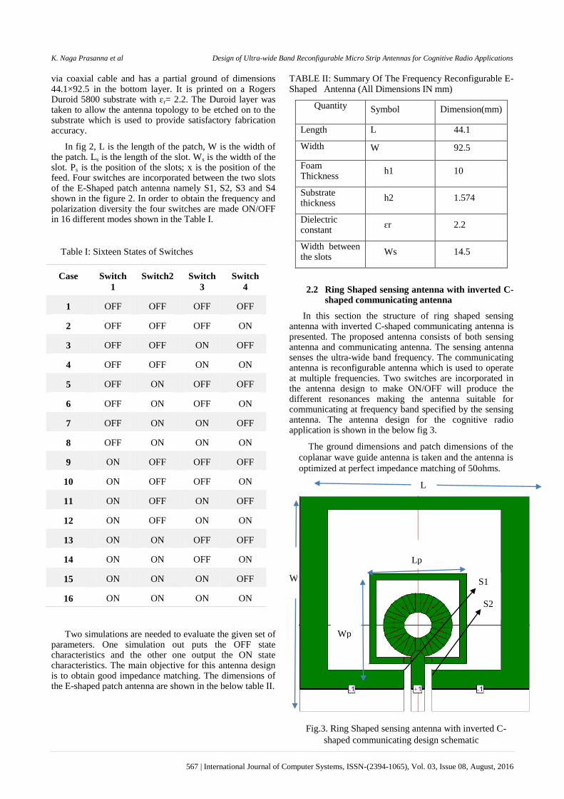
2.2 Ring Shaped sensing antenna with inverted C-shaped communicating antenna
In this section the structure of ring shaped sensing antenna with inverted C-shaped communicating antenna is presented. The proposed antenna consists of both sensing antenna and communicating antenna. The sensing antenna senses the ultra-wide band frequency. The communicating antenna is reconfigurable antenna which is used to operate at multiple frequencies. Two switches are incorporated in the antenna design to make ON/OFF will produce the different resonances making the antenna suitable for communicating at frequency band specified by the sensing antenna. The antenna design for the cognitive radio application is shown in the below fig 3.
The ground dimensions and patch dimensions of the
coplanar wave guide antenna is taken and the antenna is
optimized at perfect impedance matching of 50ohms.
Fig.3. Ring Shaped sensing antenna with inverted C-
shaped communicating design schematic
Case Switch
1
Switch2 Switch
3
Switch
4
1 OFF OFF OFF OFF
2 OFF OFF OFF ON
3 OFF OFF ON OFF
4 OFF OFF ON ON
5 OFF ON OFF OFF
6 OFF ON OFF ON
7 OFF ON ON OFF
8 OFF ON ON ON
9 ON OFF OFF OFF
10 ON OFF OFF ON
11 ON OFF ON OFF
12 ON OFF ON ON
13 ON ON OFF OFF
14 ON ON OFF ON
15 ON ON ON OFF
16 ON ON ON ON
L
W
Lp
Lp
Wp
S1
S2
K. Naga Prasanna et al Design of Ultra-wide Band Reconfigurable Micro Strip Antennas for Cognitive Radio Applications
568 | International Journal of Computer Systems, ISSN-(2394-1065), Vol. 03, Issue 08, August, 2016
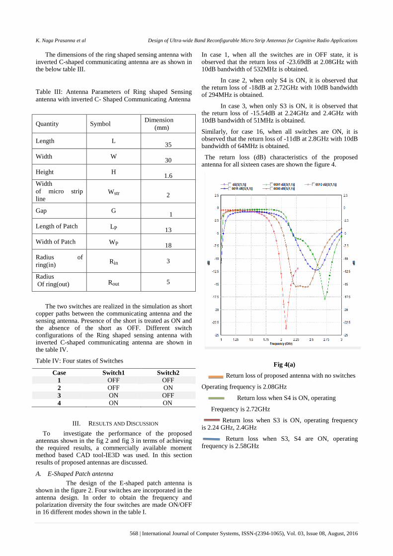
The dimensions of the ring shaped sensing antenna with inverted C-shaped communicating antenna are as shown in the below table III.
Table III: Antenna Parameters of Ring shaped Sensing
antenna with inverted C- Shaped Communicating Antenna
Quantity Symbol Dimension
(mm)
Length L
35
Width W
30
Height H
1.6
Width
of micro strip
line Wstr
2
Gap G
1
Length of Patch LP
13
Width of Patch WP
18
Radius of
ring(in) Rin
3
Radius
Of ring(out) Rout 5
The two switches are realized in the simulation as short copper paths between the communicating antenna and the sensing antenna. Presence of the short is treated as ON and the absence of the short as OFF. Different switch configurations of the Ring shaped sensing antenna with inverted C-shaped communicating antenna are shown in the table IV.
Table IV: Four states of Switches
Case Switch1 Switch2
1 OFF OFF
2 OFF ON
3 ON OFF
4 ON ON
III. RESULTS AND DISCUSSION
To investigate the performance of the proposed antennas shown in the fig 2 and fig 3 in terms of achieving the required results, a commercially available moment method based CAD tool-IE3D was used. In this section results of proposed antennas are discussed.
A. E-Shaped Patch antenna
The design of the E-shaped patch antenna is shown in the figure 2. Four switches are incorporated in the antenna design. In order to obtain the frequency and polarization diversity the four switches are made ON/OFF in 16 different modes shown in the table I.
In case 1, when all the switches are in OFF state, it is observed that the return loss of -23.69dB at 2.08GHz with 10dB bandwidth of 532MHz is obtained.
In case 2, when only S4 is ON, it is observed that the return loss of -18dB at 2.72GHz with 10dB bandwidth of 294MHz is obtained.
In case 3, when only S3 is ON, it is observed that the return loss of -15.54dB at 2.24GHz and 2.4GHz with 10dB bandwidth of 51MHz is obtained.
Similarly, for case 16, when all switches are ON, it is observed that the return loss of -11dB at 2.8GHz with 10dB bandwidth of 64MHz is obtained.
The return loss (dB) characteristics of the proposed antenna for all sixteen cases are shown the figure 4.
Fig 4(a)
Return loss of proposed antenna with no switches
Operating frequency is 2.08GHz
Return loss when S4 is ON, operating
Frequency is 2.72GHz
Return loss when S3 is ON, operating frequency is 2.24 GHz, 2.4GHz
Return loss when S3, S4 are ON, operating frequency is 2.58GHz
K. Naga Prasanna et al Design of Ultra-wide Band Reconfigurable Micro Strip Antennas for Cognitive Radio Applications
569 | International Journal of Computer Systems, ISSN-(2394-1065), Vol. 03, Issue 08, August, 2016
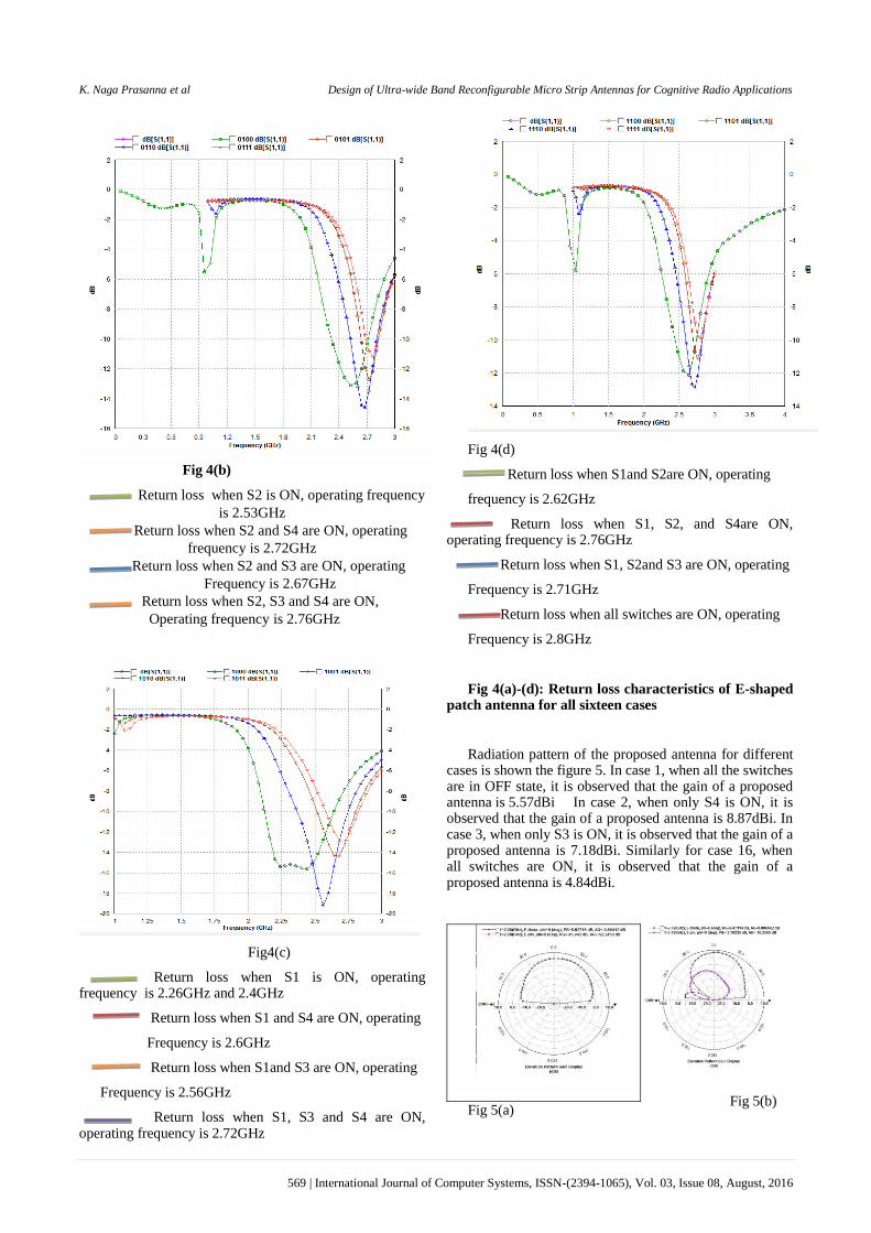
Fig 4(b)
Return loss when S2 is ON, operating frequency
is 2.53GHz
Return loss when S2 and S4 are ON, operating
frequency is 2.72GHz
Return loss when S2 and S3 are ON, operating
Frequency is 2.67GHz
Return loss when S2, S3 and S4 are ON,
Operating frequency is 2.76GHz
Fig4(c)
Return loss when S1 is ON, operating frequency is 2.26GHz and 2.4GHz
Return loss when S1 and S4 are ON, operating
Frequency is 2.6GHz
Return loss when S1and S3 are ON, operating
Frequency is 2.56GHz
Return loss when S1, S3 and S4 are ON, operating frequency is 2.72GHz
Fig 4(d)
Return loss when S1and S2are ON, operating
frequency is 2.62GHz
Return loss when S1, S2, and S4are ON, operating frequency is 2.76GHz
Return loss when S1, S2and S3 are ON, operating
Frequency is 2.71GHz
Return loss when all switches are ON, operating
Frequency is 2.8GHz
Fig 4(a)-(d): Return loss characteristics of E-shaped patch antenna for all sixteen cases
Radiation pattern of the proposed antenna for different cases is shown the figure 5. In case 1, when all the switches are in OFF state, it is observed that the gain of a proposed antenna is 5.57dBi In case 2, when only S4 is ON, it is observed that the gain of a proposed antenna is 8.87dBi. In case 3, when only S3 is ON, it is observed that the gain of a proposed antenna is 7.18dBi. Similarly for case 16, when all switches are ON, it is observed that the gain of a proposed antenna is 4.84dBi.
Fig 5(a)
Fig 5(b)
K. Naga Prasanna et al Design of Ultra-wide Band Reconfigurable Micro Strip Antennas for Cognitive Radio Applications
570 | International Journal of Computer Systems, ISSN-(2394-1065), Vol. 03, Issue 08, August, 2016
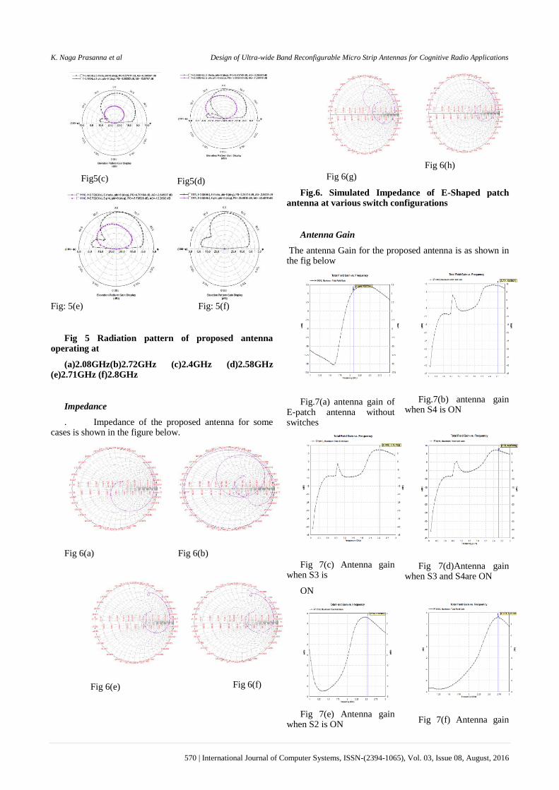
Fig5(c)
Fig5(d)
Fig: 5(e) Fig: 5(f)
Fig 5 Radiation pattern of proposed antenna operating at
(a)2.08GHz(b)2.72GHz (c)2.4GHz (d)2.58GHz (e)2.71GHz (f)2.8GHz
Impedance
. Impedance of the proposed antenna for some cases is shown in the figure below.
Fig 6(a)
Fig 6(b)
Fig 6(e)
Fig 6(f)
Fig 6(g)
Fig 6(h)
Fig.6. Simulated Impedance of E-Shaped patch antenna at various switch configurations
Antenna Gain
The antenna Gain for the proposed antenna is as shown in the fig below
Fig.7(a) antenna gain of E-patch antenna without switches
Fig.7(b) antenna gain when S4 is ON
Fig 7(c) Antenna gain when S3 is
ON
Fig 7(d)Antenna gain when S3 and S4are ON
Fig 7(e) Antenna gain when S2 is ON
Fig 7(f) Antenna gain
K. Naga Prasanna et al Design of Ultra-wide Band Reconfigurable Micro Strip Antennas for Cognitive Radio Applications
571 | International Journal of Computer Systems, ISSN-(2394-1065), Vol. 03, Issue 08, August, 2016
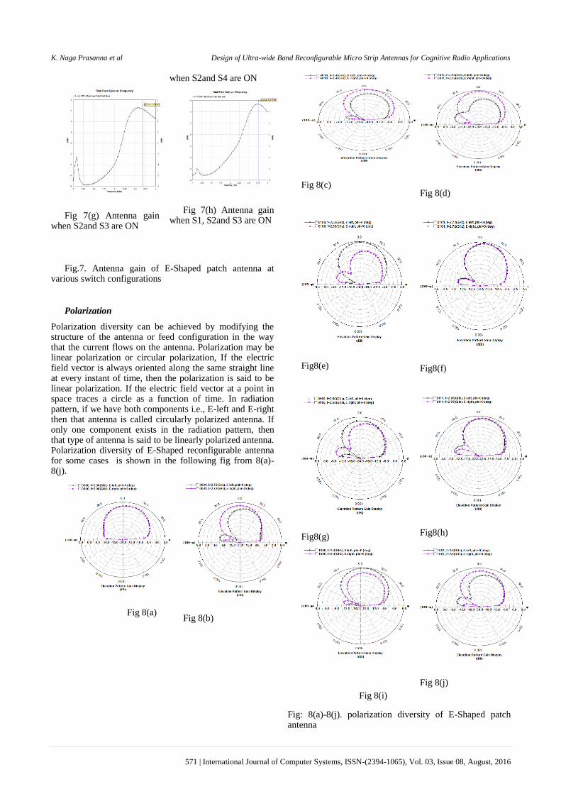
when S2and S4 are ON
Fig 7(g) Antenna gain when S2and S3 are ON
Fig 7(h) Antenna gain when S1, S2and S3 are ON
Fig.7. Antenna gain of E-Shaped patch antenna at various switch configurations
Polarization
Polarization diversity can be achieved by modifying the structure of the antenna or feed configuration in the way that the current flows on the antenna. Polarization may be linear polarization or circular polarization, If the electric field vector is always oriented along the same straight line at every instant of time, then the polarization is said to be linear polarization. If the electric field vector at a point in space traces a circle as a function of time. In radiation pattern, if we have both components i.e., E-left and E-right then that antenna is called circularly polarized antenna. If only one component exists in the radiation pattern, then that type of antenna is said to be linearly polarized antenna. Polarization diversity of E-Shaped reconfigurable antenna for some cases is shown in the following fig from 8(a)-8(j).
Fig 8(a)
Fig 8(b)
Fig 8(c)
Fig 8(d)
Fig8(e)
Fig8(f)
Fig8(g)
Fig8(h)
Fig 8(i)
Fig 8(j)
Fig: 8(a)-8(j). polarization diversity of E-Shaped patch antenna
K. Naga Prasanna et al Design of Ultra-wide Band Reconfigurable Micro Strip Antennas for Cognitive Radio Applications
572 | International Journal of Computer Systems, ISSN-(2394-1065), Vol. 03, Issue 08, August, 2016
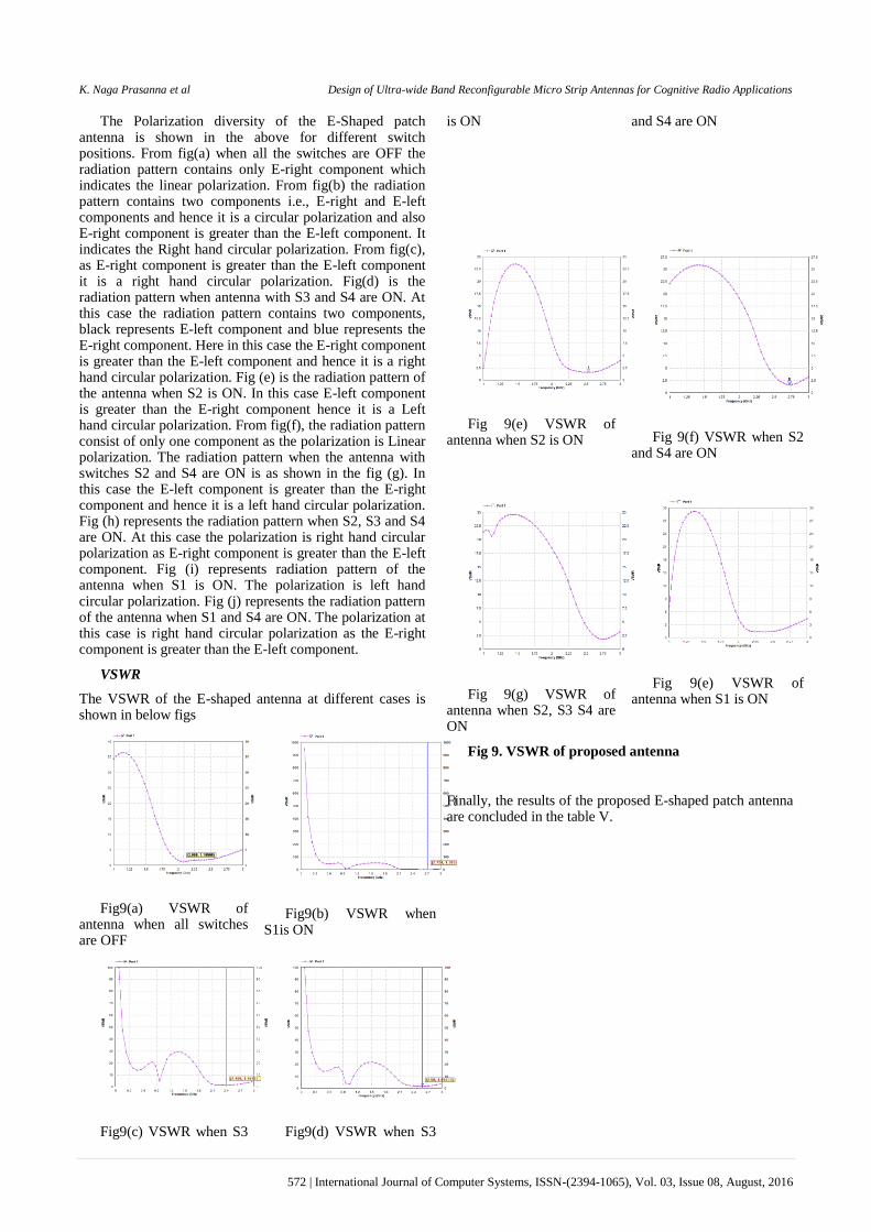
The Polarization diversity of the E-Shaped patch antenna is shown in the above for different switch positions. From fig(a) when all the switches are OFF the radiation pattern contains only E-right component which indicates the linear polarization. From fig(b) the radiation pattern contains two components i.e., E-right and E-left components and hence it is a circular polarization and also E-right component is greater than the E-left component. It indicates the Right hand circular polarization. From fig(c), as E-right component is greater than the E-left component it is a right hand circular polarization. Fig(d) is the radiation pattern when antenna with S3 and S4 are ON. At this case the radiation pattern contains two components, black represents E-left component and blue represents the E-right component. Here in this case the E-right component is greater than the E-left component and hence it is a right hand circular polarization. Fig (e) is the radiation pattern of the antenna when S2 is ON. In this case E-left component is greater than the E-right component hence it is a Left hand circular polarization. From fig(f), the radiation pattern consist of only one component as the polarization is Linear polarization. The radiation pattern when the antenna with switches S2 and S4 are ON is as shown in the fig (g). In this case the E-left component is greater than the E-right component and hence it is a left hand circular polarization. Fig (h) represents the radiation pattern when S2, S3 and S4 are ON. At this case the polarization is right hand circular polarization as E-right component is greater than the E-left component. Fig (i) represents radiation pattern of the antenna when S1 is ON. The polarization is left hand circular polarization. Fig (j) represents the radiation pattern of the antenna when S1 and S4 are ON. The polarization at this case is right hand circular polarization as the E-right component is greater than the E-left component.
VSWR
The VSWR of the E-shaped antenna at different cases is shown in below figs
Fig9(a) VSWR of antenna when all switches are OFF
Fig9(b) VSWR when S1is ON
Fig9(c) VSWR when S3
Fig9(d) VSWR when S3
is ON and S4 are ON
Fig 9(e) VSWR of antenna when S2 is ON
Fig 9(f) VSWR when S2 and S4 are ON
Fig 9(g) VSWR of antenna when S2, S3 S4 are ON
Fig 9(e) VSWR of antenna when S1 is ON
Fig 9. VSWR of proposed antenna
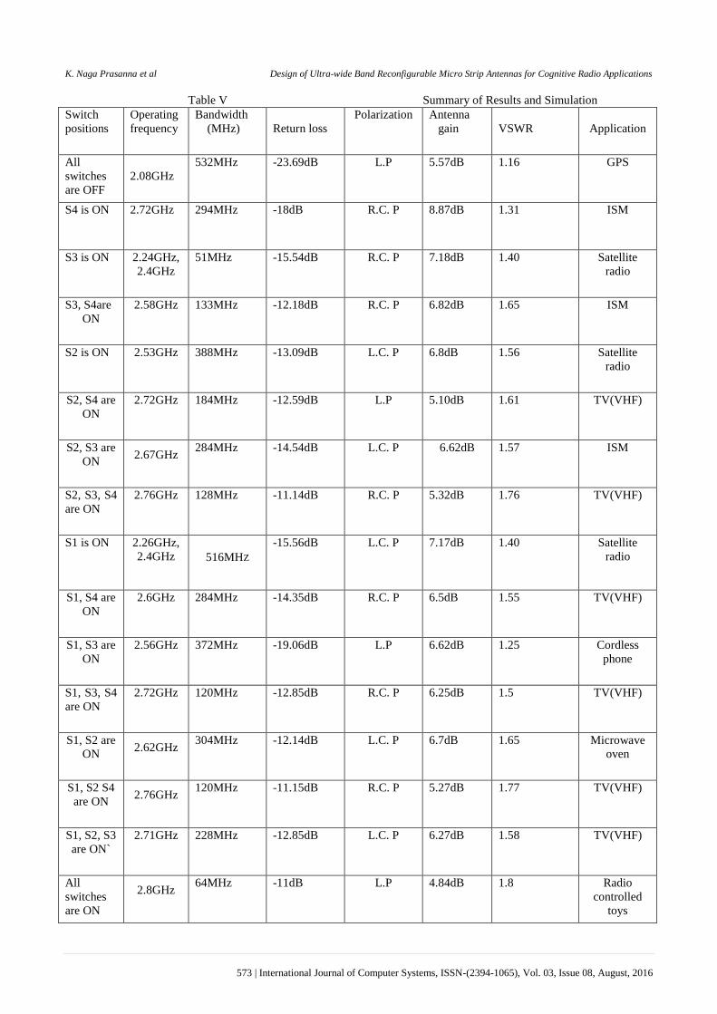
Finally, the results of the proposed E-shaped patch antenna are concluded in the table V.
K. Naga Prasanna et al Design of Ultra-wide Band Reconfigurable Micro Strip Antennas for Cognitive Radio Applications
573 | International Journal of Computer Systems, ISSN-(2394-1065), Vol. 03, Issue 08, August, 2016
Table V Summary of Results and Simulation
Switch
positions
Operating
frequency
Bandwidth
(MHz)
Return loss
Polarization Antenna
gain
VSWR
Application
All
switches
are OFF
2.08GHz
532MHz -23.69dB L.P 5.57dB 1.16 GPS
S4 is ON 2.72GHz 294MHz -18dB R.C. P 8.87dB 1.31 ISM
S3 is ON 2.24GHz,
2.4GHz
51MHz -15.54dB R.C. P 7.18dB 1.40 Satellite
radio
S3, S4are
ON
2.58GHz 133MHz -12.18dB R.C. P 6.82dB 1.65 ISM
S2 is ON 2.53GHz 388MHz -13.09dB L.C. P 6.8dB 1.56 Satellite
radio
S2, S4 are
ON
2.72GHz 184MHz -12.59dB L.P 5.10dB 1.61 TV(VHF)
S2, S3 are
ON 2.67GHz
284MHz -14.54dB L.C. P 6.62dB 1.57 ISM
S2, S3, S4
are ON
2.76GHz 128MHz -11.14dB R.C. P 5.32dB 1.76 TV(VHF)
S1 is ON 2.26GHz,
2.4GHz 516MHZ
-15.56dB L.C. P 7.17dB 1.40 Satellite
radio
S1, S4 are
ON
2.6GHz 284MHz -14.35dB R.C. P 6.5dB 1.55 TV(VHF)
S1, S3 are
ON
2.56GHz 372MHz -19.06dB L.P 6.62dB 1.25 Cordless
phone
S1, S3, S4
are ON
2.72GHz 120MHz -12.85dB R.C. P 6.25dB 1.5 TV(VHF)
S1, S2 are
ON 2.62GHz
304MHz -12.14dB L.C. P 6.7dB 1.65 Microwave
oven
S1, S2 S4
are ON 2.76GHz
120MHz -11.15dB R.C. P 5.27dB 1.77 TV(VHF)
S1, S2, S3
are ON`
2.71GHz 228MHz -12.85dB L.C. P 6.27dB 1.58 TV(VHF)
All
switches
are ON
2.8GHz
64MHz -11dB L.P 4.84dB 1.8 Radio
controlled
toys
K. Naga Prasanna et al Design of Ultra-wide Band Reconfigurable Micro Strip Antennas for Cognitive Radio Applications
574 | International Journal of Computer Systems, ISSN-(2394-1065), Vol. 03, Issue 08, August, 2016
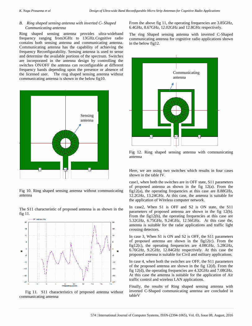
B. Ring shaped sensing antenna with inverted C- Shaped
Communicating antenna
Ring shaped sensing antenna provides ultra-wideband frequency ranging from3GHz to 13GHz.Cognitive radio contains both sensing antenna and communicating antenna. Communicating antenna has the capability of achieving the frequency Reconfigurability. Sensing antenna is used to sense and determine the available portions of the spectrum. Switches are incorporated in the antenna design by controlling the switches ON/OFF the antenna can reconfigurable at different frequency bands depending upon the presence or absence of the licensed user. The ring shaped sensing antenna without communicating antenna is shown in the below fig10.
Fig 10. Ring shaped sensing antenna without communicating antenna
The S11 characteristic of proposed antenna is as shown in the fig 11.
Fig 11. S11 characteristics of proposed antenna without communicating antenna
From the above fig 11, the operating frequencies are 3.85GHz, 6.4GHz, 8.67GHz, 12.02GHz and 12.8GHz respectively.
The ring Shaped sensing antenna with inverted C-Shaped communicating antenna for cognitive radio applications shown in the below fig12.
Fig 12. Ring shaped sensing antenna with communicating antenna
Here, we are using two switches which results in four cases shown in the table IV.
case1, when both the switches are in OFF state, S11 parameters of proposed antenna as shown in the fig 12(a). From the fig12(a), the operating frequencies at this case are 8.88GHz, 12.2GHz, 13.24GHz. At this case, the antenna is suitable for the application of Wireless computer network.
In case2, When S1 is OFF and S2 is ON state, the S11 parameters of proposed antenna are shown in the fig 12(b). From the fig12(b), the operating frequencies at this case are 5.32GHz, 6.75GHz, 9.24GHz, 12.56GHz. At this case the, antenna is suitable for the radar applications and traffic light crossing detectors.
In case 3, When S1 is ON and S2 is OFF, the S11 parameters of proposed antenna are shown in the fig12(c). From the fig12(c), the operating frequencies are 4.08GHz, 5.28GHz, 6.76GHz, 9.2GHz, 12.84GHz respectively. At this case the proposed antenna is suitable for Civil and military applications.
In case 4, when both the switches are OFF, the S11 parameters of the proposed antenna are shown in the fig 12(d). From the fig 12(d), the operating frequencies are 4.32GHz and 7.08GHz. At this case the antenna is suitable for the application of Air traffic control and wireless LAN applications.
Finally, the results of Ring shaped sensing antenna with inverted C-Shaped communicating antenna are concluded in tableV
Sensing
antenna
Communicating
antenna
K. Naga Prasanna et al Design of Ultra-wide Band Reconfigurable Micro Strip Antennas for Cognitive Radio Applications
575 | International Journal of Computer Systems, ISSN-(2394-1065), Vol. 03, Issue 08, August, 2016
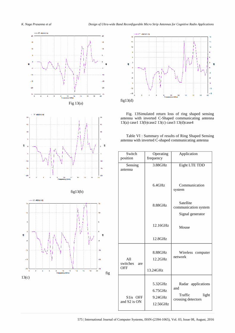
Fig 13(a)
fig13(b)
fig 13(c)
fig13(d)
Fig. 13Simulated return loss of ring shaped sensing antenna with inverted C-Shaped communicating antenna 13(a) case1 13(b)case2 13(c) case3 13(d)case4
Table VI : Summary of results of Ring Shaped Sensing antenna with inverted C-shaped communicating antenna
Switch position
Operating frequency
Application
Sensing antenna
3.88GHz
6.4GHz
8.88GHz
12.16GHz
12.8GHz
Eight LTE TDD
Communication system
Satellite communication system
Signal generator
Mouse
All switches are OFF
8.88GHz
12.2GHz
13.24GHz
Wireless computer network
S1is OFF and S2 is ON
5.32GHz
6.75GHz
9.24GHz
12.56GHz
Radar applications and
Traffic light crossing detectors

K. Naga Prasanna et al Design of Ultra-wide Band Reconfigurable Micro Strip Antennas for Cognitive Radio Applications
576 | International Journal of Computer Systems, ISSN-(2394-1065), Vol. 03, Issue 08, August, 2016
S1 is ON and S2 is OFF
4.08GHz
5.28GHz
6.76GHz
9.2GHz
12.84GHz
Civil and
military applications
All
switches are ON
4.32GHz
7.08GHz
Government institutions
Air traffic control
IV. CONCLUSION
In this paper we proposed two different frequency reconfigurable antenna designs for cognitive radio applications. In both the antenna designs Reconfigurabilty is achieved by implementing switches in antenna geometry.
First one is the E-shaped patch antenna which is designed to use as communicating antenna for CR applications. In this antenna design four switches are used, which can be turned ON/OFF to radiate signals at desired frequency within the permissible range. This antenna is designed to operate from 2.08GHz to 2.86GHz
Further another antenna which is ring shaped ultra-wide band with inverted C-shaped communicating antenna is designed. The sensing antenna is designed to operate at 3 GHz to 13.12GHz and finds out the unused spectrum over the band of frequencies whereas the communicating antenna will dynamically allocate unused spectrum to the secondary users by operating the switches at different cases. The frequency and polarization can be changed depending on the availability of band over the spectrum.
REFERENCES
[1] Harish Rajagopalan, „MEMS Reconfigurable Optimized E-Shaped Patch Antenna Design for Cognitive Radio‟
[2] J. R. Kelly and P. S. Hall, “Reconfigurable slot antenna forcognitive radio application,” IEEE Antennas and PropagationSociety International Symposium, 2009, pp. 1-4.
[3] J. Kelly, E. Ebrahimi, P. S. Hall, P. Gardner, and F Ghanem, "Combined wideband and narrowband antennas for cognitive radio applications," in The IET seminar on Cognitive Radio and Software Defined Radios: Technologies and techniques, London, UK, Sep. 2008.
[4] Y. Tawk, J. Costantine, K. Avery, andC.G. Christodoulou, “Implementation of a Cognitive Radio Front-End Using Rotatable Controlled Reconfigurable Antennas,” IEEE Trans. Antennas Propag., vol. 59, no. 5, pp. 1773-1778, May 2012.
[5] E. Erfani, J. Nourinia and C. Ghobadi, “Design and Implementation of an Integrated UWB/Reconfigurable-Slot Antenna for Cognitive Radio Applications,” IEEE Antennas Wireless Propag. Lett., vol. 11, pp. 77- 80, 2012.
[6] N. Behdad and K. Sarabandi, "Dual-band reconfigurable antenna with a very wide tunability range," Antennas and Propagation, IEEE Transactions on, vol. 54, pp. 409-416, 2006.
[7] M. Ali, A. T. M. Sayem and V. K. Kunda, "A Reconfigurable StackedMicrostrip Patch Antenna for Satellite and Terrestrial Links," Vehicular Technology, IEEE Transactions on, vol. 56, pp. 426-435, 2007.
1 K. Naga prasannareceived B.
Tech degree from Ravindra College of engineering for women, Kurnool, in Electronics and Communications Engineering and currently doing M. Tech in Digital Electronics communication systems at G. Pullaiah college of engineering and technology, Kurnool, AP.
2Dr. P. Nageswara Rao received B. Tech degree from
Nagarjuna University, Guntur, India, in Electronics and Communications Engineering and Master‟s degree from Coimbatore Institute of Technology, Coimbatore, India, in 1990 and 1995, respectively. Worked as faculty in ECE department at NBKRIST, Nellore and SreeVidyanikethan Engineering College, Tirupati for 20 years. Currently working as Principal at G. Pullaiah College of Engineering &Technology, Kurnool, A.P, and India. Areas of interest are Numerical Electromagnetic and micro strip antennas.
3Y. Anushareceived B. Tech
degree from Ravindra College of engineering for women, Kurnool, in Electronics and Communications Engineering and Master‟s degree from Pullaiah college of engineering and Technology, Kurnool, A.P, and India, in 2012 and 2014, respectively. Currently working as assistant professor at G.Pullaiah College of Engineering &Technology, Kurnool, A.P, and India. Areas of interest are Antennas and wave propagation.