Embed Size (px)
Citation preview

Heriot-Watt University Research Gateway
Design of type-1 servo controller for grid voltage modulateddirect-power control of single-phase grid-connected PV inverter
Citation for published version:Radwan, E, Nour, M, Baniyounes, A & Al-Olimat, KS 2021, 'Design of type-1 servo controller for grid voltagemodulated direct-power control of single-phase grid-connected PV inverter', International Journal ofElectrical and Computer Engineering, vol. 11, no. 3, pp. 1912-1923.https://doi.org/10.11591/ijece.v11i3.pp1912-1923
Digital Object Identifier (DOI):10.11591/ijece.v11i3.pp1912-1923
Link:Link to publication record in Heriot-Watt Research Portal
Document Version:Publisher's PDF, also known as Version of record
Published In:International Journal of Electrical and Computer Engineering
General rightsCopyright for the publications made accessible via Heriot-Watt Research Portal is retained by the author(s) and /or other copyright owners and it is a condition of accessing these publications that users recognise and abide bythe legal requirements associated with these rights.
Take down policyHeriot-Watt University has made every reasonable effort to ensure that the content in Heriot-Watt ResearchPortal complies with UK legislation. If you believe that the public display of this file breaches copyright pleasecontact [email protected] providing details, and we will remove access to the work immediately andinvestigate your claim.
Download date: 27. Nov. 2021

International Journal of Electrical and Computer Engineering (IJECE)
Vol. 11, No. 3, June 2021, pp. 1912~1923
ISSN: 2088-8708, DOI: 10.11591/ijece.v11i3.pp1912-1923 1912
Journal homepage: http://ijece.iaescore.com
Design of type-1 servo controller for grid voltage modulated
direct-power control of single-phase grid-connected PV inverter
Eyad Radwan1, Mutasim Nour2, Ali Baniyounes3, Khalid S. Al-Olimat4
1,3Department of Electrical Engineering, Applied Science Private University, Jordan 2School of Engineering and Physical Sciences, Heriot-Watt University, Dubai Campus, United Arab Emirates
4Department of Electrical & Computer Engineering and Computer Science, Ohio Northern University, United States
Article Info ABSTRACT
Article history:
Received Aug 25, 2020
Revised Oct 13, 2020
Accepted Nov 1, 2020
This paper presents direct control of active and reactive power using grid
voltage modulation for single-phase grid-connected photovoltaic inverter. A
design of type-1 servo system based on pole-placement method is proposed
to control the power flow using a simplified multiple-input multiple-output
(MIMO) model of the system. Phase-locked loop (PLL) with a quarter cycle
time delay is used to estimate the grid phase angle for the purpose of
performing the stationary and synchronous reference frame transformation.
Unipolar pulse width modulation (PWM) technique is used to control a
single-phase inverter with 2.7 KVA capacity connected to the photovoltaic
system. The proposed controller can simply be tuned using minimum number
of controller gains to achieve the transient and steady-state performance
requirements. The proposed system, was capable of operating for a wide
range of solar irradiance levels with a power factor in the range of 0.95
(leading/lagging), for the reactive power compensation purposes.
Keywords:
Decoupled control
Direct power control
Grid-connected
Renewable energy
Single-phase inverter
This is an open access article under the CC BY-SA license.
Corresponding Author:
Eyad Radwan
Department of Electrical Engineering
Applied Science Private University
Al Arab street, Amman, Jordan
Email: [email protected]
1. INTRODUCTION
Renewable energy sources, especially photovoltaic powered systems, have been increasingly used
as alternative sources of energy to power small residential and medium commercial installations. According
to IEA forecast, renewable power capacity is set to expand by 50% between 2019 and 2024, led by solar
photovoltaic (PV). This increase of 1200 GW is equivalent to the total installed power capacity of the United
States today [1].
Solar photovoltaic systems are broadly classified into standalone PV systems and grid connected PV
systems. Solar PV serves as a sole source of energy satisfying the load demand in standalone systems,
whereas in grid connected PV systems, the AC grid also supports the occurring load demand [2]. Many of the
single-phase PV systems operated in a standalone configuration, however, connecting them to grid have been
on the rise due to the advantages, such as; providing ancillary services to the utility (reactive power support),
load balancing, voltage support, and harmonic mitigation [3].
However, the increasing adoption of PV systems in a grid-connected configuration also poses more
challenging issues [4, 5]. This fact inspires the development of technologies and new researches to present
and propose new solutions to allow the connection to the grid in a safe, reliable, and efficient ways. Recent
research topics addressed techniques and improvements related to; synchronization of single-phase PV
Int J Elec & Comp Eng ISSN: 2088-8708
Design of type-1 servo controller for grid voltage modulated direct-power control … (Eyad Radwan)
1913
systems with the grid [6-8], various control methods to improve power quality such as: reduction of total
harmonic distortion [3, 9], and reactive power injection strategies [4, 10] including low voltage ride through
capabilities [11-16].
Converter control strategies such as grid voltage modulated direct power control (GVM-DPC) and
DPC based on; sliding mode control (DPC-SMC), and space vector modulation (DPC-SVM) for three-phase
grid-connected PV systems have been reported in literature [17]. Similarly, control strategies such as SMC [18],
adaptive-fuzzy SMC [19], and Adaptive Intelligent SMC [20] are also implemented to control single-phase
grid-connected PV systems.
Control strategies for single-phase grid-connected PV inverter follow similar strategies adopted in
three-phase systems with a slight difference in creating the quadrature voltage vector. However, once the
quadrature voltage signal is generated, conventional control of active and reactive power using the concept of
vector current control can be implemented in a similar manner to three-phase systems. Conventional control
methods implementing either, proportional resonant (PR) controllers in stationary α or proportional integral
(PI) controllers in rotating DQ reference frames are both widely employed for grid connected power
converters, and both strategies are able to provide a zero steady state error [21].
This paper proposes a design of a controller for single-phase PV system based on the GVM-DPC
method using servo type-1 controllers for active and reactive power regulation instead of traditional PI
controllers. The inverter-grid system is modelled first as MIMO system in state space with coupling exists
between states. However, decoupling between input and output is achieved since the system is represented in
the DQ reference frame. Coupling between the states is also removed by proper selection of the controller
gain using the pole-placement method. The paper is structured as follows; modelling of the system, design of
the controller, design of L filter and maximum power tracking point (MPPT) are given in the research
method section, the simulation results of the proposed controller are presented in the results and discussion
section, and conclusion is given the last section.
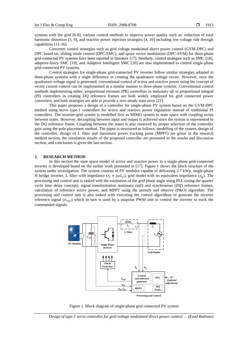
2. RESEARCH METHOD
In this section the state space model of active and reactive power in a single-phase grid-connected
inverter is developed based on the earlier work presented in [17]. Figure 1 shows the block structure of the
system under investigation. The system consists of PV modules capable of delivering 2.7 kWp, single-phase
H bridge inverter, L filter with impedance (𝑟𝑓 + 𝑗𝜔𝐿𝑓), grid model with its equivalent impedance (𝑧𝑔). The
processing and control unit is tasked with the estimation of the grid phase angle using PLL (using the quarter
cycle time delay concept), signal transformation stationary (𝛼𝛽) and synchronous (𝐷𝑄) reference frames,
calculation of reference active power, and MPPT using the perturb and observe (P&O) algorithm. The
processing and control unit is also tasked with executing the control algorithms to generate the inverter
reference signal (𝑣𝑟𝑒𝑓) which in turn is used by a unipolar PWM unit to control the inverter to track the
commanded signals.
rf
Cdc
PWM
Generator
DQ
Trans.
Control
and reference
generator
vpv, ipv
vdc
vgig
MPPT
PLLvrefQ*
(Optional
adjustment)
Processing and Control
Lf
Single Phase
inverter
vg
PV Modules
Grid Model
L Filter
zg
Figure 1. Block diagram of single-phase grid connected PV system
ISSN: 2088-8708
Int J Elec & Comp Eng, Vol. 11, No. 3, June 2021 : 1912 - 1923
1914
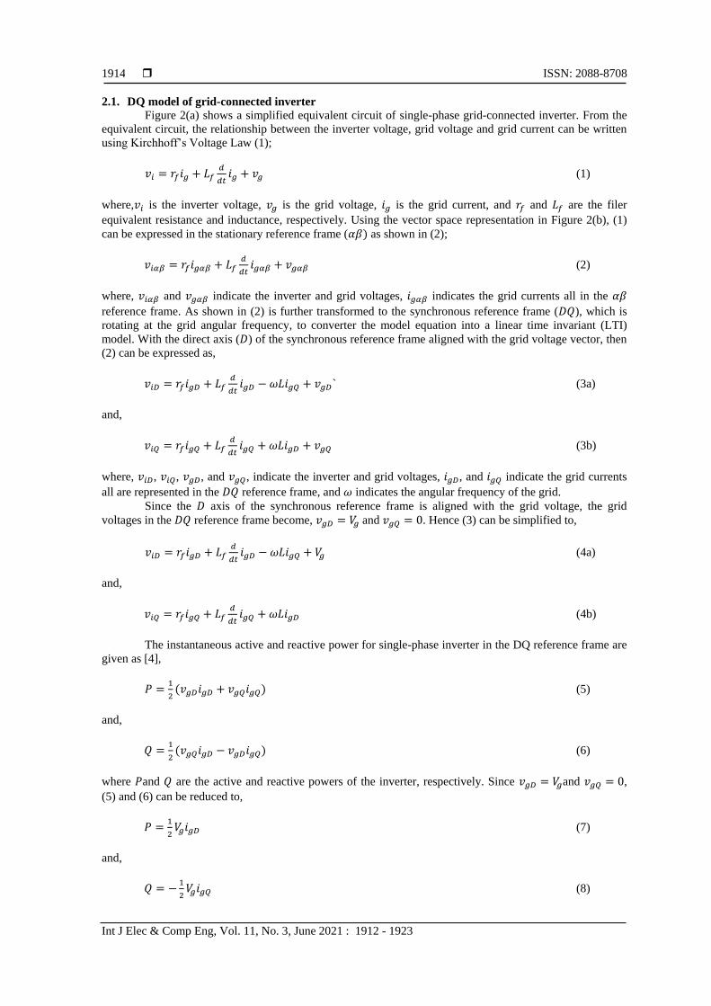
2.1. DQ model of grid-connected inverter
Figure 2(a) shows a simplified equivalent circuit of single-phase grid-connected inverter. From the
equivalent circuit, the relationship between the inverter voltage, grid voltage and grid current can be written
using Kirchhoff’s Voltage Law (1);
𝑣𝑖 = 𝑟𝑓𝑖𝑔 + 𝐿𝑓𝑑
𝑑𝑡𝑖𝑔 + 𝑣𝑔 (1)
where,𝑣𝑖 is the inverter voltage, 𝑣𝑔 is the grid voltage, 𝑖𝑔 is the grid current, and 𝑟𝑓 and 𝐿𝑓 are the filer
equivalent resistance and inductance, respectively. Using the vector space representation in Figure 2(b), (1)
can be expressed in the stationary reference frame (𝛼𝛽) as shown in (2);
𝑣𝑖𝛼𝛽 = 𝑟𝑓𝑖𝑔𝛼𝛽 + 𝐿𝑓𝑑
𝑑𝑡𝑖𝑔𝛼𝛽 + 𝑣𝑔𝛼𝛽 (2)
where, 𝑣𝑖𝛼𝛽 and 𝑣𝑔𝛼𝛽 indicate the inverter and grid voltages, 𝑖𝑔𝛼𝛽 indicates the grid currents all in the 𝛼𝛽
reference frame. As shown in (2) is further transformed to the synchronous reference frame (𝐷𝑄), which is
rotating at the grid angular frequency, to converter the model equation into a linear time invariant (LTI)
model. With the direct axis (𝐷) of the synchronous reference frame aligned with the grid voltage vector, then
(2) can be expressed as,
𝑣𝑖𝐷 = 𝑟𝑓𝑖𝑔𝐷 + 𝐿𝑓𝑑
𝑑𝑡𝑖𝑔𝐷 − 𝜔𝐿𝑖𝑔𝑄 + 𝑣𝑔𝐷` (3a)
and,
𝑣𝑖𝑄 = 𝑟𝑓𝑖𝑔𝑄 + 𝐿𝑓𝑑
𝑑𝑡𝑖𝑔𝑄 + 𝜔𝐿𝑖𝑔𝐷 + 𝑣𝑔𝑄 (3b)
where, 𝑣𝑖𝐷, 𝑣𝑖𝑄, 𝑣𝑔𝐷, and 𝑣𝑔𝑄, indicate the inverter and grid voltages, 𝑖𝑔𝐷, and 𝑖𝑔𝑄 indicate the grid currents
all are represented in the 𝐷𝑄 reference frame, and 𝜔 indicates the angular frequency of the grid.
Since the 𝐷 axis of the synchronous reference frame is aligned with the grid voltage, the grid
voltages in the 𝐷𝑄 reference frame become, 𝑣𝑔𝐷 = 𝑉𝑔 and 𝑣𝑔𝑄 = 0. Hence (3) can be simplified to,
𝑣𝑖𝐷 = 𝑟𝑓𝑖𝑔𝐷 + 𝐿𝑓𝑑
𝑑𝑡𝑖𝑔𝐷 − 𝜔𝐿𝑖𝑔𝑄 + 𝑉𝑔 (4a)
and,
𝑣𝑖𝑄 = 𝑟𝑓𝑖𝑔𝑄 + 𝐿𝑓𝑑
𝑑𝑡𝑖𝑔𝑄 + 𝜔𝐿𝑖𝑔𝐷 (4b)
The instantaneous active and reactive power for single-phase inverter in the DQ reference frame are
given as [4],
𝑃 =1
2(𝑣𝑔𝐷𝑖𝑔𝐷 + 𝑣𝑔𝑄𝑖𝑔𝑄) (5)
and,
𝑄 =1
2(𝑣𝑔𝑄𝑖𝑔𝐷 − 𝑣𝑔𝐷𝑖𝑔𝑄) (6)
where 𝑃and 𝑄 are the active and reactive powers of the inverter, respectively. Since 𝑣𝑔𝐷 = 𝑉𝑔and 𝑣𝑔𝑄 = 0,
(5) and (6) can be reduced to,
𝑃 =1
2𝑉𝑔𝑖𝑔𝐷 (7)
and,
𝑄 = −1
2𝑉𝑔𝑖𝑔𝑄 (8)

Int J Elec & Comp Eng ISSN: 2088-8708
Design of type-1 servo controller for grid voltage modulated direct-power control … (Eyad Radwan)
1915
The instantaneous variation of the active and reactive powers can be obtained by differentiating (7)
and (8) with respect to time. Assuming that the grid voltage is constant, then,
𝑑
𝑑𝑡𝑃 =
1
2𝑉𝑔
𝑑
𝑑𝑡𝑖𝑔𝐷 (9)
and,
𝑑
𝑑𝑡𝑄 = −
1
2𝑉𝑔
𝑑
𝑑𝑡𝑖𝑔𝑄 (10)
Lf rf
vgvi
ig
(a)
Q
D
ii
vg
vi
w
(b)
Figure 2. Model of single-phase grid-connected inverter, (a) equivalent circuit, (b) vector space
representation
Substituting (4a) into (9),
𝑑
𝑑𝑡𝑃 =
1
2(−
𝑟𝑓
𝐿𝑓𝑉𝑔𝑖𝑔𝐷 + 𝜔𝑉𝑔𝑖𝑔𝑄 +
1
𝐿𝑓𝑉𝑔𝑣𝑖𝐷 −
1
𝐿𝑓𝑉𝑔
2) (11)
As shown in (11) can further be simplified as,
𝑑
𝑑𝑡𝑃 = −
𝑟𝑓
𝐿𝑓𝑃 − 𝜔𝑄 +
1
2𝐿𝑓𝑉𝑔(𝑣𝑖𝐷 − 𝑉𝑔)
or,
𝑑
𝑑𝑡𝑃 = −
𝑟𝑓
𝐿𝑓𝑃 − 𝜔𝑄 +
1
2𝐿𝑓(𝑣𝐷 − 𝑉𝑔
2) (12)
similarly, from (4b) and (10),
𝑑
𝑑𝑡𝑄 = 𝜔𝑃 −
𝑟𝑓
𝐿𝑓𝑄 −
1
2𝐿𝑓𝑣𝑄 (13)
From (12) and (13) a state space model for the single-phase grid-connected inverter can be developed as,
[
] = [−
𝑟𝑓
𝐿𝑓−𝜔
𝜔 −𝑟𝑓
𝐿𝑓
] [𝑃𝑄
] + [
1
2𝐿𝑓0
0−1
2𝐿𝑓
] [𝑣𝐷
𝑣𝑄] + [
−1
2𝐿𝑓
0]𝑉𝑔
2 (14a)
where, [𝑃 𝑄]𝑇is the state vector, [𝑣𝐷 𝑣𝑄]𝑇 is the input vector, [−1
2𝐿𝑓0]
𝑇
is disturbance vector, 𝑣𝐷 = 𝑉𝑔𝑣𝑖𝐷,
and 𝑣𝑄 = 𝑉𝑔𝑣𝑖𝑄. The output equation can also be written as,
[𝑦1
𝑦2] = [
1 00 1
] [𝑃𝑄
] (14b)
ISSN: 2088-8708
Int J Elec & Comp Eng, Vol. 11, No. 3, June 2021 : 1912 - 1923
1916
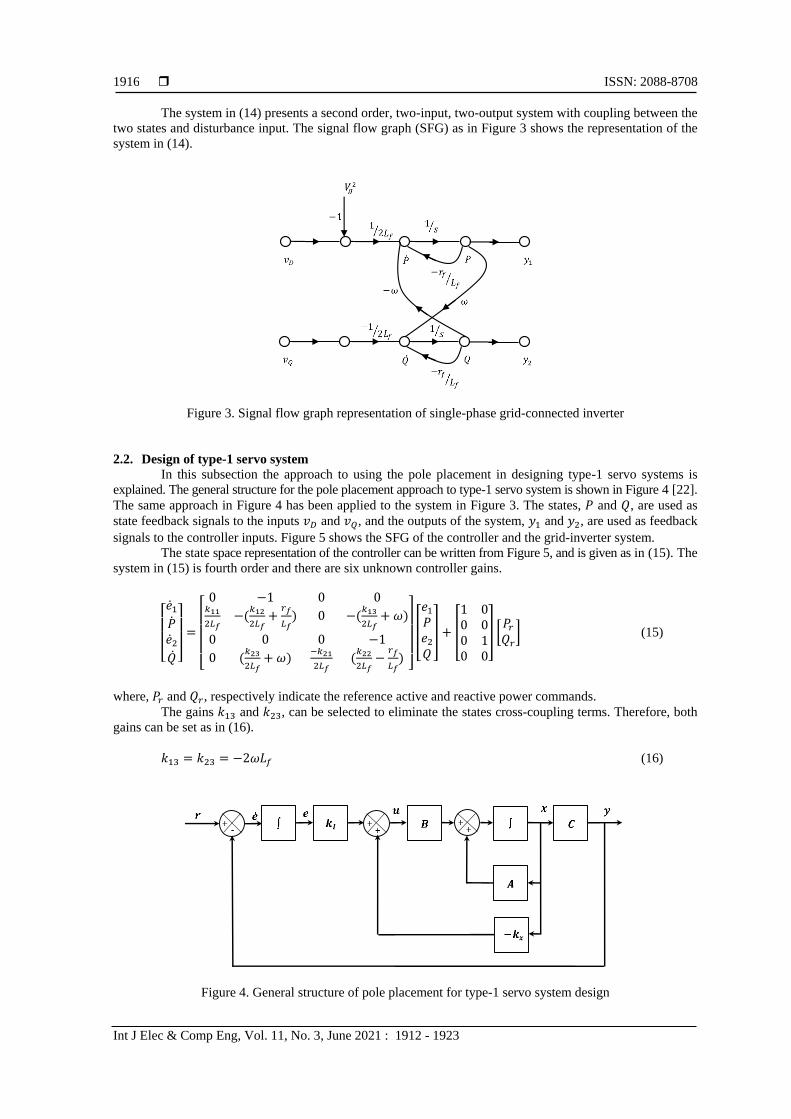
The system in (14) presents a second order, two-input, two-output system with coupling between the
two states and disturbance input. The signal flow graph (SFG) as in Figure 3 shows the representation of the
system in (14).
Figure 3. Signal flow graph representation of single-phase grid-connected inverter
2.2. Design of type-1 servo system
In this subsection the approach to using the pole placement in designing type-1 servo systems is
explained. The general structure for the pole placement approach to type-1 servo system is shown in Figure 4 [22].
The same approach in Figure 4 has been applied to the system in Figure 3. The states, 𝑃 and 𝑄, are used as
state feedback signals to the inputs 𝑣𝐷 and 𝑣𝑄, and the outputs of the system, 𝑦1 and 𝑦2, are used as feedback
signals to the controller inputs. Figure 5 shows the SFG of the controller and the grid-inverter system.
The state space representation of the controller can be written from Figure 5, and is given as in (15). The
system in (15) is fourth order and there are six unknown controller gains.
[ 1
𝑃2
]
=
[ 0 −1 0 0
𝑘11
2𝐿𝑓−(
𝑘12
2𝐿𝑓+
𝑟𝑓
𝐿𝑓) 0 −(
𝑘13
2𝐿𝑓+ 𝜔)
0 0 0 −1
0 (𝑘23
2𝐿𝑓+ 𝜔)
−𝑘21
2𝐿𝑓(𝑘22
2𝐿𝑓−
𝑟𝑓
𝐿𝑓)
]
[
𝑒1
𝑃𝑒2
𝑄
] + [
1 00 00 10 0
] [𝑃𝑟
𝑄𝑟] (15)
where, 𝑃𝑟 and 𝑄𝑟, respectively indicate the reference active and reactive power commands.
The gains 𝑘13 and 𝑘23, can be selected to eliminate the states cross-coupling terms. Therefore, both
gains can be set as in (16).
𝑘13 = 𝑘23 = −2𝜔𝐿𝑓 (16)
Figure 4. General structure of pole placement for type-1 servo system design
Int J Elec & Comp Eng ISSN: 2088-8708
Design of type-1 servo controller for grid voltage modulated direct-power control … (Eyad Radwan)
1917
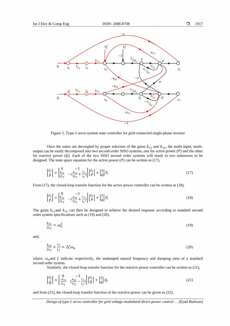
Figure 5. Type-1 servo system state controller for grid-connected single-phase inverter
Once the states are decoupled by proper selection of the gains 𝑘13 and 𝑘23, the multi-input, multi-
output can be easily decomposed into two second-order SISO systems; one for active power (𝑃) and the other
for reactive power (𝑄). Each of the two SISO second order systems will result in two unknowns to be
designed. The state space equation for the active power (𝑃) can be written as (17),
[𝑒1
] = [
0 −1𝑘11
2𝐿𝑓−(
𝑘12
2𝐿𝑓+
𝑟𝑓
𝐿𝑓)] [
𝑒1
𝑃] + [
10] 𝑃𝑟 (17)
From (17), the closed-loop transfer function for the active power controller can be written as (18),
[𝑒1
] = [
0 −1𝑘11
2𝐿𝑓−(
𝑘12
2𝐿𝑓+
𝑟𝑓
𝐿𝑓)] [
𝑒1
𝑃] + [
10] 𝑃𝑟 (18)
The gains 𝑘11and 𝑘12 can then be designed to achieve the desired response according to standard second
order system specifications such as (19) and (20);
𝑘11
2𝐿𝑓= 𝜔𝑛
2 (19)
and,
𝑘12
2𝐿𝑓+
𝑟𝑓
𝐿𝑓= 2𝜁𝜔𝑛 (20)
where, 𝜔𝑛and 𝜁 indicate respectively, the undamped natural frequency and damping ratio of a standard
second order system.
Similarly, the closed-loop transfer function for the reactive power controller can be written as (21),
[𝑒2
] = [
0 −1−𝑘21
2𝐿𝑓(𝑘22
2𝐿𝑓−
𝑟𝑓
𝐿𝑓)] [
𝑒2
𝑄] + [10]𝑄𝑟 (21)
and from (21), the closed-loop transfer function of the reactive power can be given as (22),
ISSN: 2088-8708
Int J Elec & Comp Eng, Vol. 11, No. 3, June 2021 : 1912 - 1923
1918
𝑄(𝑠)
𝑄𝑟(𝑠)=
−𝑘21 2𝐿𝑓⁄
𝑠2−(𝑘222𝐿𝑓
−𝑟𝑓
𝐿𝑓)𝑠−
𝑘212𝐿𝑓
(22)
again, the gains 𝑘21and 𝑘22 can be designed based on desired second order system specifications.
2.3. Design of L filter and MPPT
An L filter is used to reduce the high-order current harmonics produced by the inverter at switching
frequency. The L filter is designed using the methodology presented in [23]. The maximum value of the filter
total inductance (𝐿𝑓𝑚𝑎𝑥) is given as,
𝐿𝑓𝑚𝑎𝑥 =𝑣𝑔
2
2𝜋𝑓𝑃 × 10% (23)
where, 𝑣𝑔 and 𝑓 indicate respectively the grid voltage and frequency, and 𝑃 is the power of the inverter.
However, to achieve an acceptable current THD at low power levels this requires an increase in the value of
the filter inductor, thus (23) is applied at half the inverter rated power.
To guarantee that maximum power is being extracted from a PV array and transferred to grid/ load
system at all times, MPPT control algorithms are usually used for this purpose. In recent years, a large
number of MPPT techniques have been proposed for tracking the maximum power point. Proposed
techniques vary in terms of complexity, accuracy, efficiency, and hardware requirements. Classical MPPT
techniques such as; perturb and observe (P&O), incremental conductance (IC), and ripple correlation (RC)
methods are deemed to be suitable and practical [24].
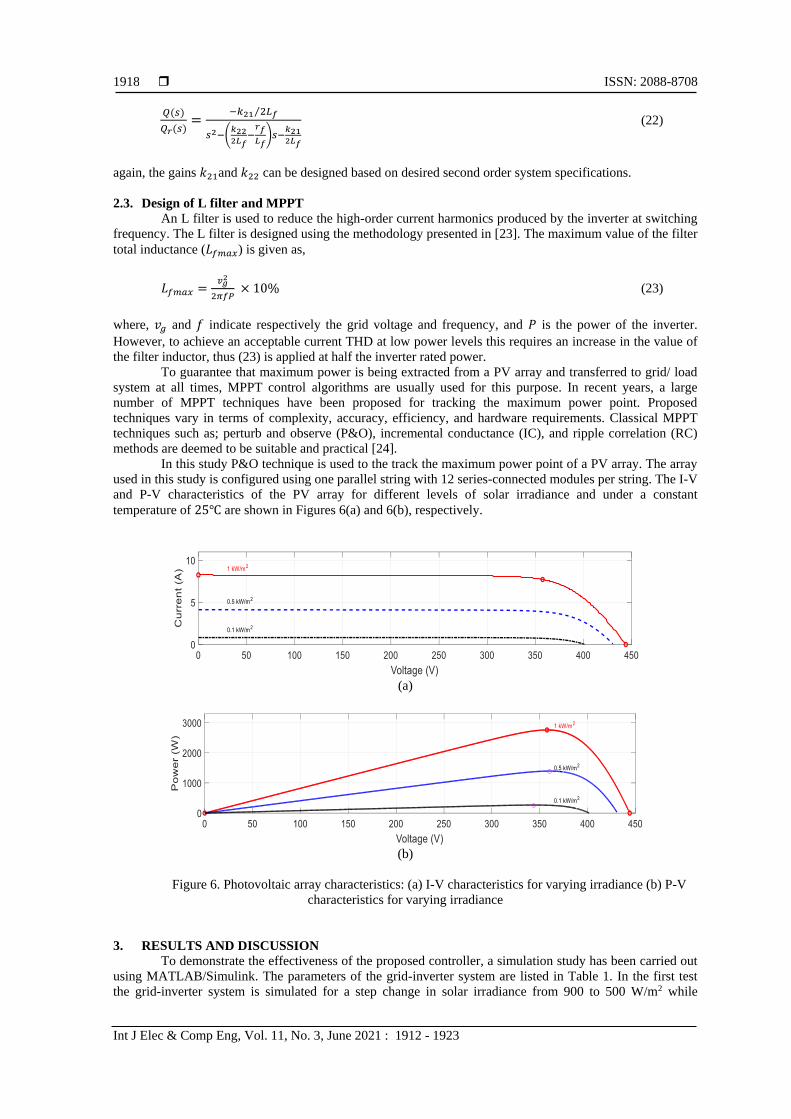
In this study P&O technique is used to the track the maximum power point of a PV array. The array
used in this study is configured using one parallel string with 12 series-connected modules per string. The I-V
and P-V characteristics of the PV array for different levels of solar irradiance and under a constant
temperature of 25 are shown in Figures 6(a) and 6(b), respectively.
(a)
(b)
Figure 6. Photovoltaic array characteristics: (a) I-V characteristics for varying irradiance (b) P-V
characteristics for varying irradiance
3. RESULTS AND DISCUSSION
To demonstrate the effectiveness of the proposed controller, a simulation study has been carried out
using MATLAB/Simulink. The parameters of the grid-inverter system are listed in Table 1. In the first test
the grid-inverter system is simulated for a step change in solar irradiance from 900 to 500 W/m2 while
Int J Elec & Comp Eng ISSN: 2088-8708
Design of type-1 servo controller for grid voltage modulated direct-power control … (Eyad Radwan)
1919
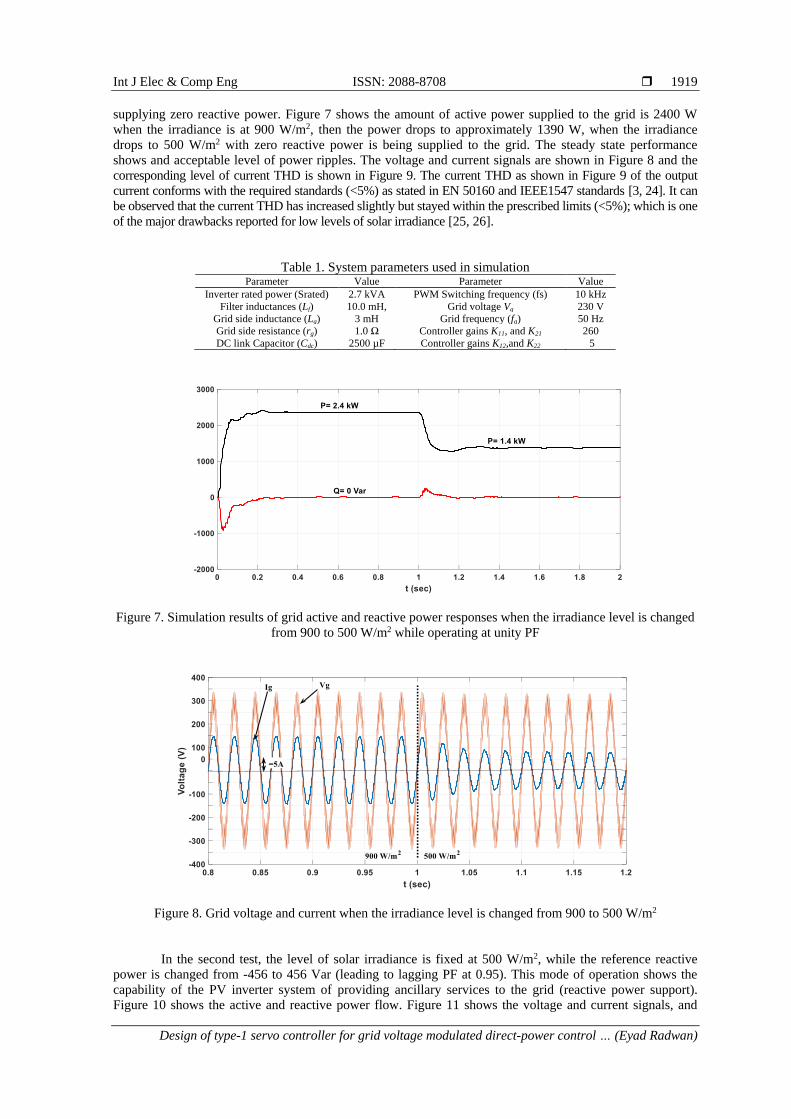
supplying zero reactive power. Figure 7 shows the amount of active power supplied to the grid is 2400 W
when the irradiance is at 900 W/m2, then the power drops to approximately 1390 W, when the irradiance
drops to 500 W/m2 with zero reactive power is being supplied to the grid. The steady state performance
shows and acceptable level of power ripples. The voltage and current signals are shown in Figure 8 and the
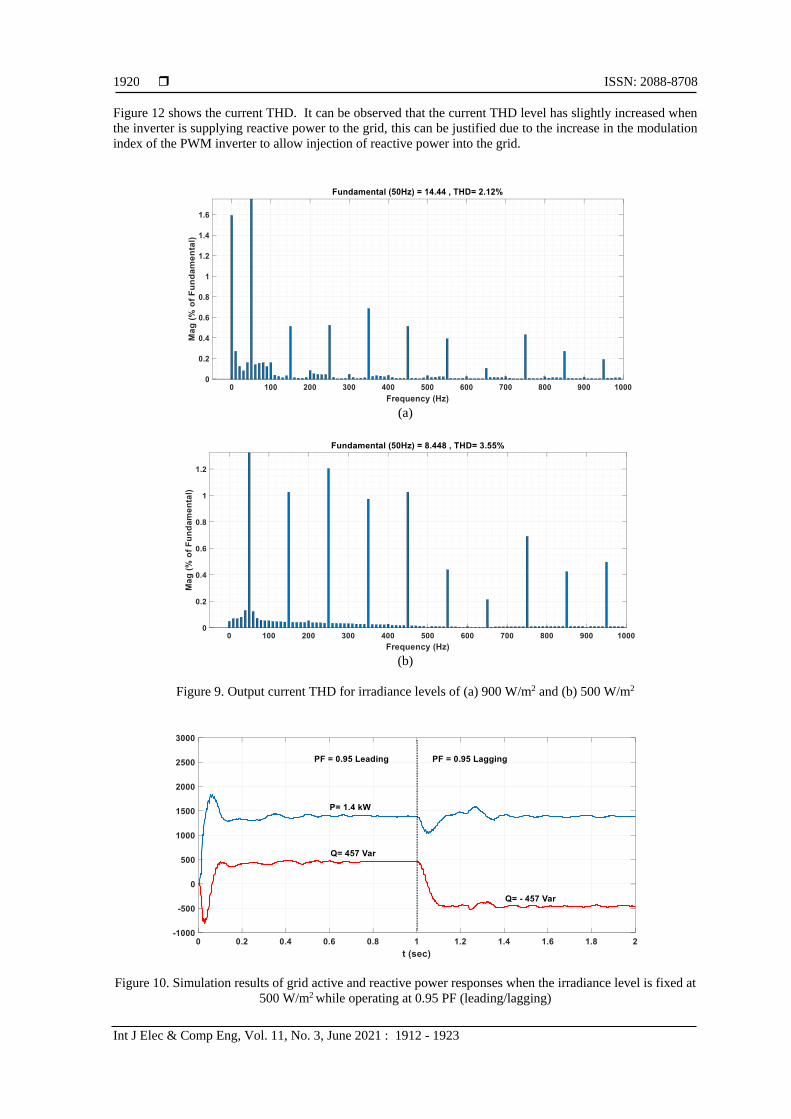
corresponding level of current THD is shown in Figure 9. The current THD as shown in Figure 9 of the output
current conforms with the required standards (<5%) as stated in EN 50160 and IEEE1547 standards [3, 24]. It can
be observed that the current THD has increased slightly but stayed within the prescribed limits (<5%); which is one
of the major drawbacks reported for low levels of solar irradiance [25, 26].
Table 1. System parameters used in simulation Parameter Value Parameter Value
Inverter rated power (Srated) 2.7 kVA PWM Switching frequency (fs) 10 kHz
Filter inductances (Lf) 10.0 mH, Grid voltage Vg 230 V
Grid side inductance (Lg) 3 mH Grid frequency (fg) 50 Hz
Grid side resistance (rg) 1.0 Ω Controller gains K11, and K21 260
DC link Capacitor (Cdc) 2500 µF Controller gains K12,and K22 5
Figure 7. Simulation results of grid active and reactive power responses when the irradiance level is changed
from 900 to 500 W/m2 while operating at unity PF
Figure 8. Grid voltage and current when the irradiance level is changed from 900 to 500 W/m2
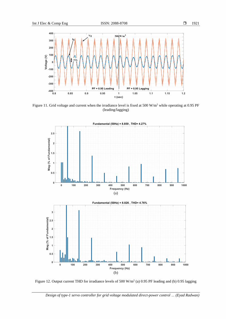
In the second test, the level of solar irradiance is fixed at 500 W/m2, while the reference reactive
power is changed from -456 to 456 Var (leading to lagging PF at 0.95). This mode of operation shows the
capability of the PV inverter system of providing ancillary services to the grid (reactive power support).
Figure 10 shows the active and reactive power flow. Figure 11 shows the voltage and current signals, and
ISSN: 2088-8708
Int J Elec & Comp Eng, Vol. 11, No. 3, June 2021 : 1912 - 1923
1920
Figure 12 shows the current THD. It can be observed that the current THD level has slightly increased when
the inverter is supplying reactive power to the grid, this can be justified due to the increase in the modulation
index of the PWM inverter to allow injection of reactive power into the grid.
(a)
(b)
Figure 9. Output current THD for irradiance levels of (a) 900 W/m2 and (b) 500 W/m2
Figure 10. Simulation results of grid active and reactive power responses when the irradiance level is fixed at
500 W/m2 while operating at 0.95 PF (leading/lagging)
Int J Elec & Comp Eng ISSN: 2088-8708
Design of type-1 servo controller for grid voltage modulated direct-power control … (Eyad Radwan)
1921
Figure 11. Grid voltage and current when the irradiance level is fixed at 500 W/m2 while operating at 0.95 PF
(leading/lagging)
(a)
(b)
Figure 12. Output current THD for irradiance levels of 500 W/m2 (a) 0.95 PF leading and (b) 0.95 lagging

ISSN: 2088-8708
Int J Elec & Comp Eng, Vol. 11, No. 3, June 2021 : 1912 - 1923
1922
4. CONCLUSION
In this study the operation of a single-phase grid-connected PV inverter system has been examined
when controlled using type-1 servo system based on pole-placement method. A simple tuning method for the
controller gains has been proposed in this study to eliminate the coupling that exists between the active and
reactive power control loops, and also to achieve acceptable transient and steady state performances. The
controller has been used to directly regulate inverter’s active and reactive power flow. The PV inverter has
been operated with a flexible reactive power compensation mode to provide ancillary services to the grid.
This compensation scheme becomes very useful when it is triggered by the voltage level at the PCC, or
alternatively used to comply with reactive power demands set by the grid operator. The simulation results
showed that when the solar irradiance is at full level, the THD of the grid-injected current conforms with
required standards. However, for low levels of solar irradiance, the THD in the grid-injected current
increased slightly, but stayed within the prescribed limits.
ACKNOWLEDGEMENTS
The researchers are grateful to the Applied Science Private University (ASU) Amman, Jordan for
the full financial support grated to this research project.
REFERENCES [1] “IEA website,” 2020. [Online]. Available: https://www.iea.org/fuels-and-technologies/.
[2] S. Sundaram, et al., “Grid Connected Photovoltaic Systems: Challenges and Control Solutions-A Potential
Review,” International Journal of Electronics and Electrical Engineering, vol. 4, no. 6, pp. 463-473, 2016.
[3] V. Beena, et al., “Active and Reactive Power Control of Single Phase Transformerless Grid Connected Inverter for
Distributed Generation System,” International Journal of Applied Engineering Research, vol. 13, no. 1, pp. 150-157, 2018.
[4] Y. Yang, et al., “Reactive Power Injection Strategies for Single-Phase Photovoltaic Systems Considering Grid
Requirements,” IEEE Transactions on Industry Applications, vol. 50, no. 6, pp. 4065-4076, 2014.
[5] A. M. Baniyounes, “Renewable energy potential in Jordan,” International Journal of Applied Engineering
Research, vol. 12, no. 19, pp. 8323-8331, 2017.
[6] E. Radwan, et al., “Modified Phase Locked Loop for Grid Connected Single Phase Inverter,” International Journal
of Electrical and Computer Engineering (IJECE), vol. 9, no. 5, pp. 3934-3943, 2019.
[7] F. Xiao, et al., “A Novel Open-Loop Frequency Estimation Method for Single-Phase Grid Synchronization Under
Distorted Conditions,” IEEE Journal of Emerging and Selected Topics in Power Electronics, vol. 5, no. 3,
pp. 1287-1297, 2017.
[8] L. Hadjidemetriou, et al., “A Synchronization Scheme for Single-Phase Grid-Tied Inverters under Harmonic
Distortion and Grid Disturbances,” IEEE Transactions on Power Electronics, vol. 32, no. 4, pp. 2784-2793, 2017.
[9] M. Prodanovic, et al., “Harmonic and Reactive Power Compensation as Ancillary Services in Inverter Based
Distributed Generation,” IET Generation, Transmission & Distribution, vol. 1, no. 3, pp. 432-438, 2007.
[10] G. M. Tina and G. Celsa, “Active and Reactive Power Regulation in Grid-Connected PV Systems,” 2015 50th
International Universities Power Engineering Conference (UPEC), Stoke on Trent, 2015, pp. 1-6.
[11] E .Radwan, et al., “Fuzzy Logic Control for Low-Voltage Ride-Through Single-Phase Grid-Connected PV
Inverter,” Energies, vol. 12, no. 24, p. 4796, 2019.
[12] S. Sadat and J. Patel, “A Review of Low Voltage Ride-Through Capability Techniques for Photovoltaic Power Plant
Systems,” International Journal of Innovative Science and Modern Engineering (IJISME), vol. 5, pp. 633-640, 2019.
[13] A. Benali, et al., “M. Power Quality Improvement and Low Voltage Ride Throught Capability in Hybrid Wind-PV
Farms Grid-Connected Using Dynamic Voltage Restorer,” IEEE Access, vol. 6, pp. 68634-68648, 2018.
[14] Y. Sravanthi and P. Sujatha, “Fuzzy Logic Controller for Low Voltage Ride through Capability Improvement of
Grid Connected Photovoltaic Power Plants,” International Journal of Advanced Research in Electrical, Electronics
and Instrumentation Engineering, vol. 6, no. 9, pp. 7213-7226, 2017.
[15] K. Li, et al., “Research on Low Voltage Ride Through of the Grid-Connected PV System,” In Proceedings of the
International Conference on Advances in Energy, Environment and Chemical Engineering, 2015, Changsha, China, 2015.
[16] Y. Yang and F. Blaabjerg, “Low-Voltage Ride-Through Capability of a Single-Stage Single-Phase Photovoltaic
System Connected to the Low-Voltage Grid,” International Journal of Photoenergy, vol. 2013, no. 1, pp. 1-9, 2013.
[17] Y. Gui, et al., “Control of Grid-connected Voltage-Source Converters: The relationship between Direct-Power
Control and Vector-Current Control,” IEEE Industrial Electronics Magazine, vol. 13, no. 2, pp. 31-40, 2019.
[18] J. Fei and Y. Zhu, “Adaptive Fuzzy Sliding Control of Single-Phase PV Grid-Connected Inverter,” PLOS ONE,
vol. 12, no. 8, 2017.
[19] S. A. A. Fallahzadeh, et al., “Sliding Mode Control of Single Phase Grid Connected PV System Using Sign
Function,” 2017 IEEE 4th International Conference on Knowledge-Based Engineering and Innovation (KBEI),
Tehran, 2017, pp. 0391-0397.
[20] Y. Fang et al., “Adaptive Intelligent Sliding Mode Control of a Photovoltaic Grid-Connected Inverter,” Applied
Sciences, vol. 8, no. 10, p. 1756, 2018.

Int J Elec & Comp Eng ISSN: 2088-8708
Design of type-1 servo controller for grid voltage modulated direct-power control … (Eyad Radwan)
1923
[21] W. Zhang, et al., “A Proportional Resonant Controller Tuning Method for Grid connected Power Converters with
LCL+trap Filter,” 2014 International Conference on Renewable Energy Research and Application (ICRERA),
Milwaukee, WI, 2014, pp. 445-450.
[22] K. Ogata, “Modern Control Engineering,” Prentice Hall, 5th edition, 2010.
[23] M. Hlaili and H. Mechergui, “Comparison of Different MPPT Algorithms with a Proposed One Using a Power
Estimator for Grid Connected PV Systems,” International Journal of Photoenergy, vol. 2016, pp. 1-10, 2016.
[24] B. S. Sotirios, et al., “ANN and Fuzzy Logic Controller Design for Hybrid Wind/PV System Connected to MV
Distribution Grid,” International Journal of Energy Sector Management, vol. 2, no. 4, pp. 499-520, 2008.
[25] S. O. Amrouche, et al., “Reactive Power Issues in Grid Connected Photovoltaic Systems,” NuRER-4 International
Conference on Nuclear and Renewable Energy Resources, Antalya, Turkey, 2014.
[26] C. Hicks, et al., “Power Quality of Residential PV System under Low Solar Irradiance and Off-Grid Operation,”
2018 18th International Conference on Harmonics and Quality of Power (ICHQP), Ljubljana, 2018, pp. 1-5.