Embed Size (px)
Citation preview

1
Design of tunable magnets for 12 MeV Race - Track Microtron
Juan Pablo Rigla Pérez, Yuri Kubyshin and Vasily Shvedunov.
10 November 2011
2
1.- Introduction: 12 MeV Race-Track Microtron of the UPC.
2.- End magnet design.3.- End magnet tuning system.
3.1.- Simulation of tuners.3.2.- Tuning ranges and interdependence.3.3.- Tuning procedure.
4.- Summary of the results and conclusions.
IndexJuan Pablo Rigla Pérez

3
1.- 12 MeV Race – Track Microtron of the UPC.
Race – Track Microtron components,
(1) Electron gun, (2) Linac, (3-4) End magnets, (5) Quadrupole, (6) Extraction magnet,(7) Extracted beam.
• The Technical University of Catalonia (UPC) , the Skobeltsyn Institute of Nuclear Physics (SINP - Moscow State University) and CIEMAT are building a race-track microtron (RTM).
• A possible future application of this RTM is Intraoperative Radiation Therapy.
Beam energies 6,8,10,12 MeV
Operating frequency 5712 MHz
End magnet field 0.8 T
Maximun beam current <2.5 μA
RTM head dimensions 670x250x210 mm
RTM head weight < 100 kg
Juan Pablo Rigla Pérez
4
Juan Pablo Rigla Pérez
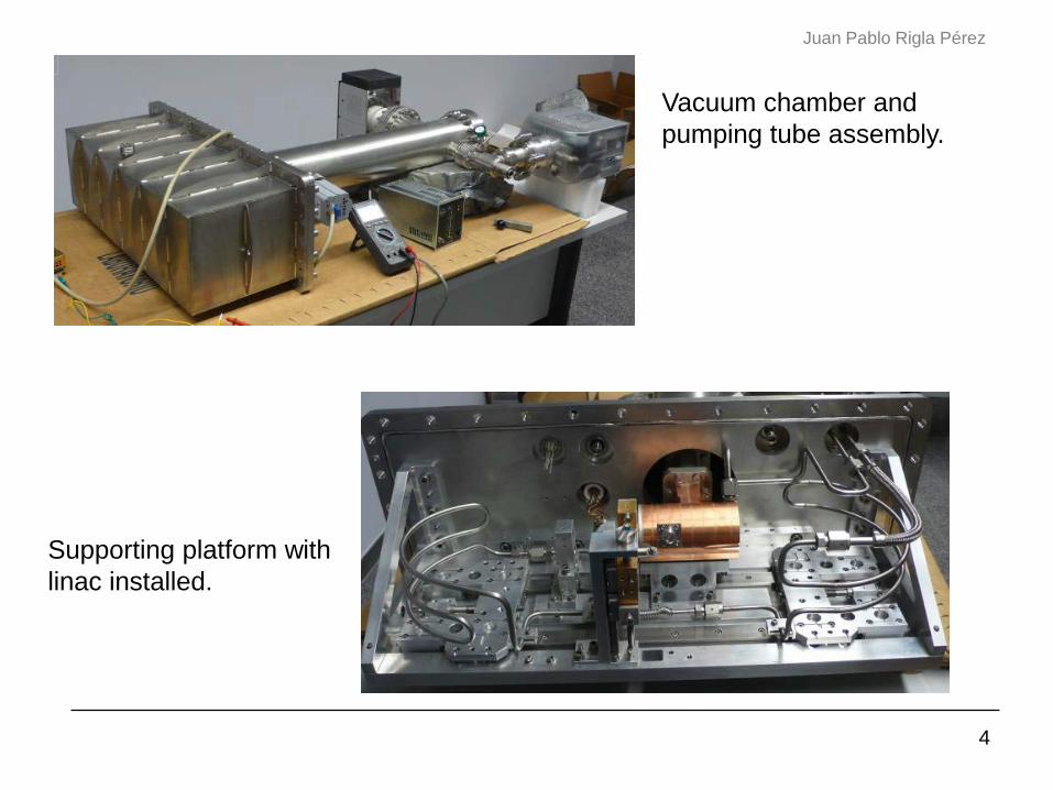
Supporting platform with linac installed.
Vacuum chamber and pumping tube assembly.
5
Juan Pablo Rigla Pérez2.- End magnet design.
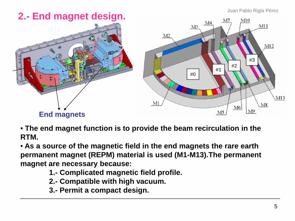
• The end magnet function is to provide the beam recirculation in the RTM.• As a source of the magnetic field in the end magnets the rare earth permanent magnet (REPM) material is used (M1-M13).The permanent magnet are necessary because:
1.- Complicated magnetic field profile.2.- Compatible with high vacuum.3.- Permit a compact design.
End magnets
#0#1
#2#3

6
Juan Pablo Rigla Pérez
End magnet external dimensions.
•The end magnet is formed by: One 180º - dipole (main pole) (0), One reverse field magnet (1) Two additional dipoles (2,3).

7
Juan Pablo Rigla Pérez
Beam trajectory for first orbit.
• Reverse field magnet: Compensate the defocusing effect by the fringe field.• Additional dipoles: Reflect the first orbit back to the linac axis.
Pole 0Pole 1Pole 2Pole 3

8
End magnet field profile in the orbit plane.Juan Pablo Rigla Pérez
Reverse pole
Main pole
Additional pole 1
Additional pole 2
The residual magnetization of REPM blocks are:
BrM1=BrM2=BrM3=1.06 T.BrM4=BrM5=0.0663 T.
Design requeriments,
43
0
0 1010 −− −=∆BB
32
3,2,1
3,2,1 1010 −− −=∆BB

9
Juan Pablo Rigla Pérez
3.- End magnet tuning sytem.• The magnetic systems must reproduce the field found in beam dynamics simulations with:
• Field Uniformity:•Absolute field value:•Equality of field of two magnets:
• In electromagnets: the magetic field adjustament is achieved by varying the current in the coils.
• In permanent magnets some tuning mechanisms are used:1.- Magnetization and desmagnetization.2.- Tuning with plungers.3.- Tuning with rotating blocks.
For the tuning of the RTM end magnet we decided to use a system of plungers.
310−
4105 −x410−

10
Tuning process.Juan Pablo Rigla Pérez
-V0
+V0
V=0
V0=0
V0=0
∞=µg
0
00 2µ
gBV =
V=0
11
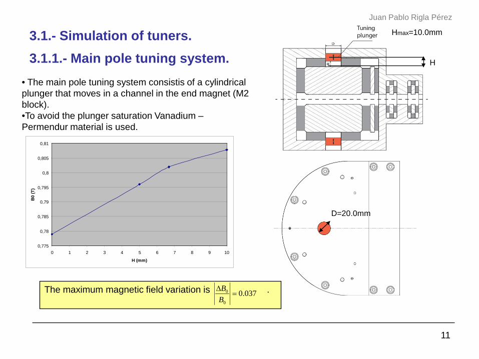
3.1.- Simulation of tuners.Juan Pablo Rigla Pérez
• The main pole tuning system consistis of a cylindrical plunger that moves in a channel in the end magnet (M2 block).•To avoid the plunger saturation Vanadium –Permendur material is used.
Hmax=10.0mm
D=20.0mm
The maximum magnetic field variation is .
0,775
0,78
0,785
0,79
0,795
0,8
0,805
0,81
0 1 2 3 4 5 6 7 8 9 10
H (mm)
B0 (T
)
3.1.1.- Main pole tuning system. H
037.00
0 =∆BB

12
3.1.2.- Reverse pole tuning system.
Six tuners of 5.0 mm
diameter
Six tuners of 5.0 mm
diameter
Juan Pablo Rigla Pérez
0,106
0,108
0,11
0,112
0,114
0,116
0,118
0 0,5 1 1,5 2 2,5 3 3,5 4 4,5 5
h2 (mm)
B1 (T
)
The maximum magnetic field variation is .
• Reverse pole tuning: a system of six tuners that moves horizontally to the reverse pole.• The M4 height was reduced to allow the motion of the plungers.
36.5 mm
086.01
1 =∆BB
h2max=5.0mm

13
3.1.3.- Additional pole tuning system.Juan Pablo Rigla Pérez
•Additional poles tuning: a system formed by five tuners (diameter 4.5mm) that move vertically in the REPM blocks M7 and M11. • To allow tuners movements we perform a channels in REPM blocks M7 and M11.
The maximum magnetic field variation is .
0,232
0,234
0,236
0,238
0,24
0,242
0,244
0,246
0,248
1 1,5 2 2,5 3 3,5 4 4,5 5h3 (mm)
B2 (T
)
h3
0473.02
2 =∆BB

14
Juan Pablo Rigla Pérez
0,116
0,1165
0,117
0,1175
0,118
0,1185
0,119
0,1195
0,12
0,1205
0,121
0,1215
0 1 2 3 4 5 6 7 8 9 10
H (mm)
B1 (T
)
3.2.- Tuning ranges and interdependence.
In the ANSYS simulations it was obtained that a variation of the position of the main pole plunger affects the magnetic field in the reverse pole.

15
Juan Pablo Rigla Pérez
0,8076
0,8078
0,808
0,8082
0,8084
0,8086
0,8088
0,809
0,8092
0,8094
0 0,5 1 1,5 2 2,5 3 3,5 4 4,5 5
h2 (mm)
B0 (T
)
And vice versa, a variation of the position of the reverse pole plunger, h2, changes the magnetic field in the main pole.

16
3.3.- Tuning procedure.
0,78
0,785
0,79
0,795
0,8
0,805
0,81
0,815
0 2 4 6 8 10 12
H (mm)
|B0|
(T)
By means of ANSYS simulations it was found that the nominal values of the magnet field:
B0=0.79826 T B1=0.116 T
are obtained at the median tuner positions:H=5.0mmh2=2.5mm
for the residual magnetizations:BrM1=BrM2=BrM3=1.0628 T.BrM4=BrM5=0.1278 T.

17
4.- Summary results and conclusions.Juan Pablo Rigla Pérez
Pole
Main Pole 0.037
Reverse Pole 0.086
Additional Poles 0.047
• Future work: Once the magnets are manufactured, apply this tuning process.
• The results obtained in the ANSYS simulations are,
• For magnetic field tuning we must use a combination of the demagnetization technique and tuning with plungers. The procedure is the following:- magnetize REPM to maximum level of Br=1.1 – 1.2 T.- measure field level and in 1-2 steps by applying demagnetizing field reduce the field level to the range found in ANSYS simulations with respect to the nominal level.- By moving the plunger, make the most difficult step, to adjust the magnetic field level.
nn BB∆

18
Juan Pablo Rigla Pérez
Thank You