Embed Size (px)
Citation preview

The University of AkronIdeaExchange@UAkron
Honors Research Projects The Dr. Gary B. and Pamela S. Williams HonorsCollege
Spring 2015
Design of the Structural and Propulsion Systemsfor the 2015 University of Akron Rocket TeamKyle W. DeHoffUniversity of Akron Main Campus, [email protected]
Nicholas J. HruschUniversity of Akron Main Campus, [email protected]
Please take a moment to share how this work helps you through this survey. Your feedback will beimportant as we plan further development of our repository.Follow this and additional works at: http://ideaexchange.uakron.edu/honors_research_projects
Part of the Aeronautical Vehicles Commons, Navigation, Guidance, Control and DynamicsCommons, Other Aerospace Engineering Commons, Other Mechanical Engineering Commons,Propulsion and Power Commons, Structures and Materials Commons, and the Systems Engineeringand Multidisciplinary Design Optimization Commons
This Honors Research Project is brought to you for free and open access by The Dr. Gary B. and Pamela S. WilliamsHonors College at IdeaExchange@UAkron, the institutional repository of The University of Akron in Akron, Ohio,USA. It has been accepted for inclusion in Honors Research Projects by an authorized administrator ofIdeaExchange@UAkron. For more information, please contact [email protected], [email protected].
Recommended CitationDeHoff, Kyle W. and Hrusch, Nicholas J., "Design of the Structural and Propulsion Systems for the 2015 Universityof Akron Rocket Team" (2015). Honors Research Projects. 52.http://ideaexchange.uakron.edu/honors_research_projects/52

4/23/2015
DESIGN OF THE STRUCTURAL AND PROPULSION
SYSTEMS FOR THE 2015 UNIVERSITY OF AKRON
ROCKET TEAM
Written by | Kyle DeHoff, Nicholas Hrusch, Joshua Wolfe

2
Dedicated to Cindy
3
Contents Propulsion Team ............................................................................................................................. 6
Introduction ................................................................................................................................. 6
Motor ........................................................................................................................................... 6
Nozzle.......................................................................................................................................... 7
Fuel .............................................................................................................................................. 8
Connection to Structure ............................................................................................................... 9
Simulation and Testing Tools ....................................................................................................... 10
Thrust Curve Test Stand ............................................................................................................ 10
OpenRocket ............................................................................................................................... 10
BurnSim .................................................................................................................................... 12
Propulsion Theory ......................................................................................................................... 13
Flight Stages .............................................................................................................................. 13
Total and Specific Impulse ........................................................................................................ 14
Stability ..................................................................................................................................... 15
Nozzle Theory ........................................................................................................................... 16
Equations ................................................................................................................................... 18
Isentropic Flow Nozzle Equations ......................................................................................... 18
Thermodynamic Properties for Gas Mixtures ....................................................................... 19
Determining Combustion Chamber Pressure ........................................................................ 19
Nozzle Area Ratios ................................................................................................................ 21
Thrust ..................................................................................................................................... 21
Tsiolkovsky Rocket Equation ................................................................................................ 21
Example Calculation .............................................................................................................. 22
First Stage Propulsion System Design .......................................................................................... 24
Design Intent ............................................................................................................................. 24
Motor Case ................................................................................................................................ 25
Nozzle........................................................................................................................................ 29
End Bulkhead ............................................................................................................................ 35
Mounting Features..................................................................................................................... 37
Welded Flange ....................................................................................................................... 38
Support Block ........................................................................................................................ 40
Centering Ring ....................................................................................................................... 43
4
Interface with Guidance Systems .............................................................................................. 43
Custom Fuel .............................................................................................................................. 46
Commercial Motor Selection .................................................................................................... 48
1st Stage Final Custom Propulsion Design ................................................................................ 50
Structure Team .............................................................................................................................. 52
Introduction ............................................................................................................................... 52
Airframe .................................................................................................................................... 52
Components ............................................................................................................................... 54
Skin ........................................................................................................................................ 54
Bulkheads .............................................................................................................................. 55
Stage Separation .................................................................................................................... 55
Determining Structural Loads ....................................................................................................... 56
Second Stage ............................................................................................................................. 56
Entire Rocket ............................................................................................................................. 66
Challenges Overcome ............................................................................................................... 68
Structural Component Design ....................................................................................................... 69
Bulkheads .................................................................................................................................. 69
Variants .................................................................................................................................. 69
Material Selection .................................................................................................................. 71
Design and Calculation .......................................................................................................... 71
Thrust Ring ................................................................................................................................ 73
Design .................................................................................................................................... 73
Weld....................................................................................................................................... 73
Skin............................................................................................................................................ 74
Material Selection .................................................................................................................. 74
Attachment............................................................................................................................. 75
Manufacturing ....................................................................................................................... 76
Threaded Rods........................................................................................................................... 77
Factors of Safety........................................................................................................................ 79
Structure................................................................................................................................. 79
Fasteners ................................................................................................................................ 83
Stage Separation............................................................................................................................ 84
Types ......................................................................................................................................... 84
5
First Design Iteration ................................................................................................................. 86
Second Design Iteration ............................................................................................................ 87
Calculations ............................................................................................................................... 88
Manufacturing and Assembly ....................................................................................................... 91
Manufacturing ........................................................................................................................... 91
Assembly ................................................................................................................................... 93
Rocket Team Experience .............................................................................................................. 96
Challenges ................................................................................................................................. 96
System Interfacing ................................................................................................................. 96
Issues Encountered ................................................................................................................ 97
Proposed Solutions .................................................................................................................... 98
References ..................................................................................................................................... 99
Appendix ..................................................................................................................................... 101
Variables Index ....................................................................................................................... 101
Propulsion Variables............................................................................................................ 101
Depiction of Important Structural Variables ....................................................................... 102
Determining Structural Load Variables ............................................................................... 103
Skin Variables...................................................................................................................... 103
Factors of Safety Variables .................................................................................................. 103
Example Structural Calculations ............................................................................................. 104
Shear and Moment Weight Distribution Extended Example .............................................. 104
Additional Bulkhead FEA Results .......................................................................................... 105
Avionics Top Bulkhead ....................................................................................................... 105
Avionics Bottom Bulkhead ................................................................................................. 105
Payload Bulkhead ................................................................................................................ 106
Engine Backstop (Stage Separation) ................................................................................... 106
Hobart Weld Filler Diagram ................................................................................................... 107
Part Drawings .......................................................................................................................... 108
Propulsion System Drawings............................................................................................... 108
Structural System Drawings ................................................................................................ 117
6
Propulsion Team
Introduction
The propulsion team was responsible for the subsystems involved in powering the flight
of the rocket. There are several important components to consider from a propulsion standpoint,
including the size and power of the motors themselves, the design of the nozzles used, the
desired flight dynamics, and the attachment of the motor to the overall structure. This section
provides an introduction to each primary propulsion component.
Motor
The motor itself is of course the most obvious component associated with the propulsion
team. The rest of the rocket is essentially built around the motor, and its selection is critical to
achieving the desired flight performance.
The motor is essentially a pressure vessel with the fore end sealed to contain the pressure
from combustion. The aft end of the motor case contains the nozzle. The motor case itself is
protected from the intense heat of the combustion by a thin layer of phenolic liner, which fits
snuggly within the motor case. The solid rocket propellant is then fit snugly within the phenolic
liner.
Figure 1: Cross-section of a solid fuel rocket motor indicating primary components
Fore Aft
End
Bulkhead
Motor Case Phenolic
Liner
Nozzle Seals
Solid
Propellant
Fuel Grains
7
Nozzle
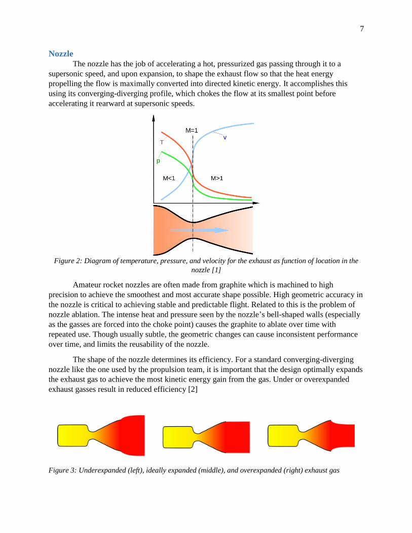
The nozzle has the job of accelerating a hot, pressurized gas passing through it to a
supersonic speed, and upon expansion, to shape the exhaust flow so that the heat energy
propelling the flow is maximally converted into directed kinetic energy. It accomplishes this
using its converging-diverging profile, which chokes the flow at its smallest point before
accelerating it rearward at supersonic speeds.
Figure 2: Diagram of temperature, pressure, and velocity for the exhaust as function of location in the
nozzle [1]
Amateur rocket nozzles are often made from graphite which is machined to high
precision to achieve the smoothest and most accurate shape possible. High geometric accuracy in
the nozzle is critical to achieving stable and predictable flight. Related to this is the problem of
nozzle ablation. The intense heat and pressure seen by the nozzle’s bell-shaped walls (especially
as the gasses are forced into the choke point) causes the graphite to ablate over time with
repeated use. Though usually subtle, the geometric changes can cause inconsistent performance
over time, and limits the reusability of the nozzle.
The shape of the nozzle determines its efficiency. For a standard converging-diverging
nozzle like the one used by the propulsion team, it is important that the design optimally expands
the exhaust gas to achieve the most kinetic energy gain from the gas. Under or overexpanded
exhaust gasses result in reduced efficiency [2]
Figure 3: Underexpanded (left), ideally expanded (middle), and overexpanded (right) exhaust gas
8
Longer nozzles with shallower angles in the diverging section yield more efficiency, but at the
cost of increased viscous drag and weight. In general, a 15 degree cone half angle in the
diverging section of the nozzle provides a good balance between weight and nozzle efficiency.
This design is commonly used and provides around a 98% efficiency [3].
A more thorough introduction to nozzle theory is found on page 15.
Fuel
Rockets may be powered by solid fuel, liquid fuel, or be some hybrid of both. In general,
solid fuel rockets are considerably simpler given the lack of need for injection systems, pumps,
and high-pressure liquid fuel storage. For our competition, a solid fuel design was used.
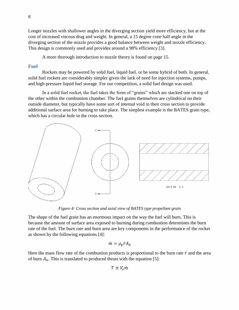
In a solid fuel rocket, the fuel takes the form of “grains” which are stacked one on top of
the other within the combustion chamber. The fuel grains themselves are cylindrical on their
outside diameter, but typically have some sort of internal void in their cross section to provide
additional surface area for burning to take place. The simplest example is the BATES grain type,
which has a circular hole in the cross section.
Figure 4: Cross section and axial view of BATES type propellant grain
The shape of the fuel grain has an enormous impact on the way the fuel will burn. This is
because the amount of surface area exposed to burning during combustion determines the burn
rate of the fuel. The burn rate and burn area are key components in the performance of the rocket
as shown by the following equations [4]:
�̇� = 𝜌𝑝�̇�𝐴𝑏
Here the mass flow rate of the combustion products is proportional to the burn rate �̇� and the area
of burn 𝐴𝑏. This is translated to produced thrust with the equation [5]:
𝑇 ≅ 𝑉𝑒�̇�
9
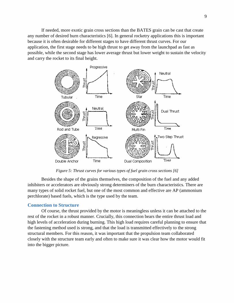
If needed, more exotic grain cross sections than the BATES grain can be cast that create
any number of desired burn characteristics [6]. In general rocketry applications this is important
because it is often desirable for different stages to have different thrust curves. For our
application, the first stage needs to be high thrust to get away from the launchpad as fast as
possible, while the second stage has lower average thrust but lower weight to sustain the velocity
and carry the rocket to its final height.
Figure 5: Thrust curves for various types of fuel grain cross sections [6]
Besides the shape of the grains themselves, the composition of the fuel and any added
inhibiters or accelerators are obviously strong determiners of the burn characteristics. There are
many types of solid rocket fuel, but one of the most common and effective are AP (ammonium
perchlorate) based fuels, which is the type used by the team.
Connection to Structure
Of course, the thrust provided by the motor is meaningless unless it can be attached to the
rest of the rocket in a robust manner. Crucially, this connection bears the entire thrust load and
high levels of acceleration during burning. This high load requires careful planning to ensure that
the fastening method used is strong, and that the load is transmitted effectively to the strong
structural members. For this reason, it was important that the propulsion team collaborated
closely with the structure team early and often to make sure it was clear how the motor would fit
into the bigger picture.
10
Simulation and Testing Tools
Thrust Curve Test Stand
Our advisor Chris Pearson uses a test stand to generate the thrust curves for a given motor
and fuel grain configuration. It is equipped with a fixture for attaching motors and a strain gauge
for measuring the reaction thrust loading. This stand allows for the testing of up to two inch
motor types, and its results can be scaled up to suit similarly configured larger-class motors. The
team is scheduled to meet with Mr. Pearson and develop thrust curves for the custom fuel grains
that were cast.
OpenRocket
One of the primary tools used to simulate the flight dynamics of the rocket is
OpenRocket. This program allows the user to build a close facsimile of the rocket and simulate
its flight path under variable conditions, including weather, launch angle, and location of the
launchsite. It is free and open source Java software that is cross-platform for Windows and Unix-
like operating systems [7]. OpenRocket was a fast and easy to use method of simulating the
rocket’s performance against our competition-specified altitude of 25,000ft, and provides figures
and values that proved highly useful across all design teams.
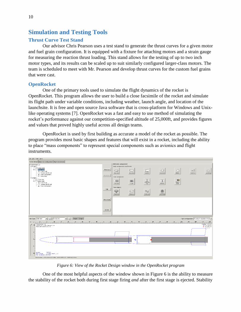
OpenRocket is used by first building as accurate a model of the rocket as possible. The
program provides most basic shapes and features that will exist in a rocket, including the ability
to place “mass components” to represent special components such as avionics and flight
instruments.
Figure 6: View of the Rocket Design window in the OpenRocket program
One of the most helpful aspects of the window shown in Figure 6 is the ability to measure
the stability of the rocket both during first stage firing and after the first stage is ejected. Stability
11
is covered in more detail in the Stability section on page 14, but in essence, OpenRocket allows
the designer to see exactly where the center of gravity (CG, the blue dot near the middle) and the
center of pressure (CP, the red dot aft of the CG) lie. By tweaking the size and shape of fins as
well as the overall mass distribution of the rocket, OpenRocket can be used to get a good early
sense of how stable the rocket will be. Doing so requires as much detail as possible to be
included in the simulation. As the location and weight of bulkheads, electronics, parachutes etc.
become known, they should be added to the simulation to make sure the rocket remains stable as
the design changes.
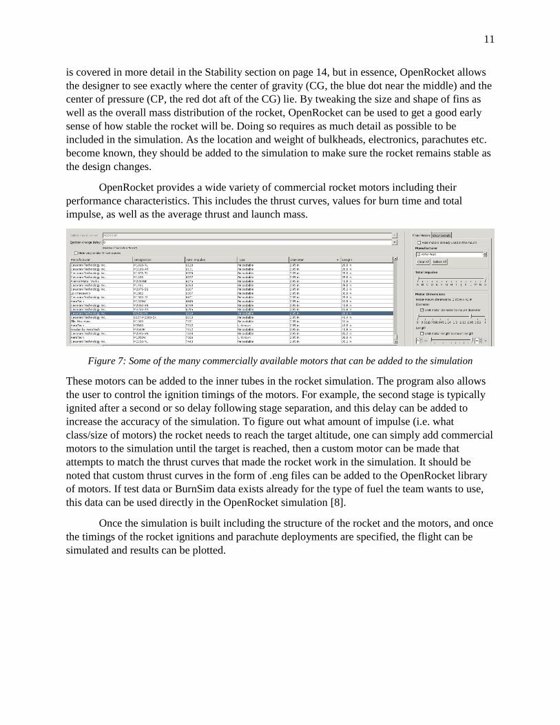
OpenRocket provides a wide variety of commercial rocket motors including their
performance characteristics. This includes the thrust curves, values for burn time and total
impulse, as well as the average thrust and launch mass.
Figure 7: Some of the many commercially available motors that can be added to the simulation
These motors can be added to the inner tubes in the rocket simulation. The program also allows
the user to control the ignition timings of the motors. For example, the second stage is typically
ignited after a second or so delay following stage separation, and this delay can be added to
increase the accuracy of the simulation. To figure out what amount of impulse (i.e. what
class/size of motors) the rocket needs to reach the target altitude, one can simply add commercial
motors to the simulation until the target is reached, then a custom motor can be made that
attempts to match the thrust curves that made the rocket work in the simulation. It should be
noted that custom thrust curves in the form of .eng files can be added to the OpenRocket library
of motors. If test data or BurnSim data exists already for the type of fuel the team wants to use,
this data can be used directly in the OpenRocket simulation [8].
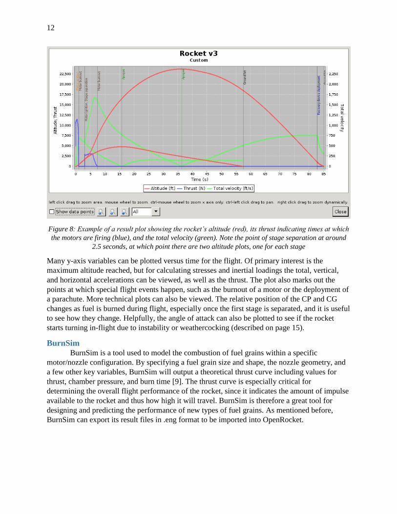
Once the simulation is built including the structure of the rocket and the motors, and once
the timings of the rocket ignitions and parachute deployments are specified, the flight can be
simulated and results can be plotted.
12
Figure 8: Example of a result plot showing the rocket’s altitude (red), its thrust indicating times at which
the motors are firing (blue), and the total velocity (green). Note the point of stage separation at around
2.5 seconds, at which point there are two altitude plots, one for each stage
Many y-axis variables can be plotted versus time for the flight. Of primary interest is the
maximum altitude reached, but for calculating stresses and inertial loadings the total, vertical,
and horizontal accelerations can be viewed, as well as the thrust. The plot also marks out the
points at which special flight events happen, such as the burnout of a motor or the deployment of
a parachute. More technical plots can also be viewed. The relative position of the CP and CG
changes as fuel is burned during flight, especially once the first stage is separated, and it is useful
to see how they change. Helpfully, the angle of attack can also be plotted to see if the rocket
starts turning in-flight due to instability or weathercocking (described on page 15).
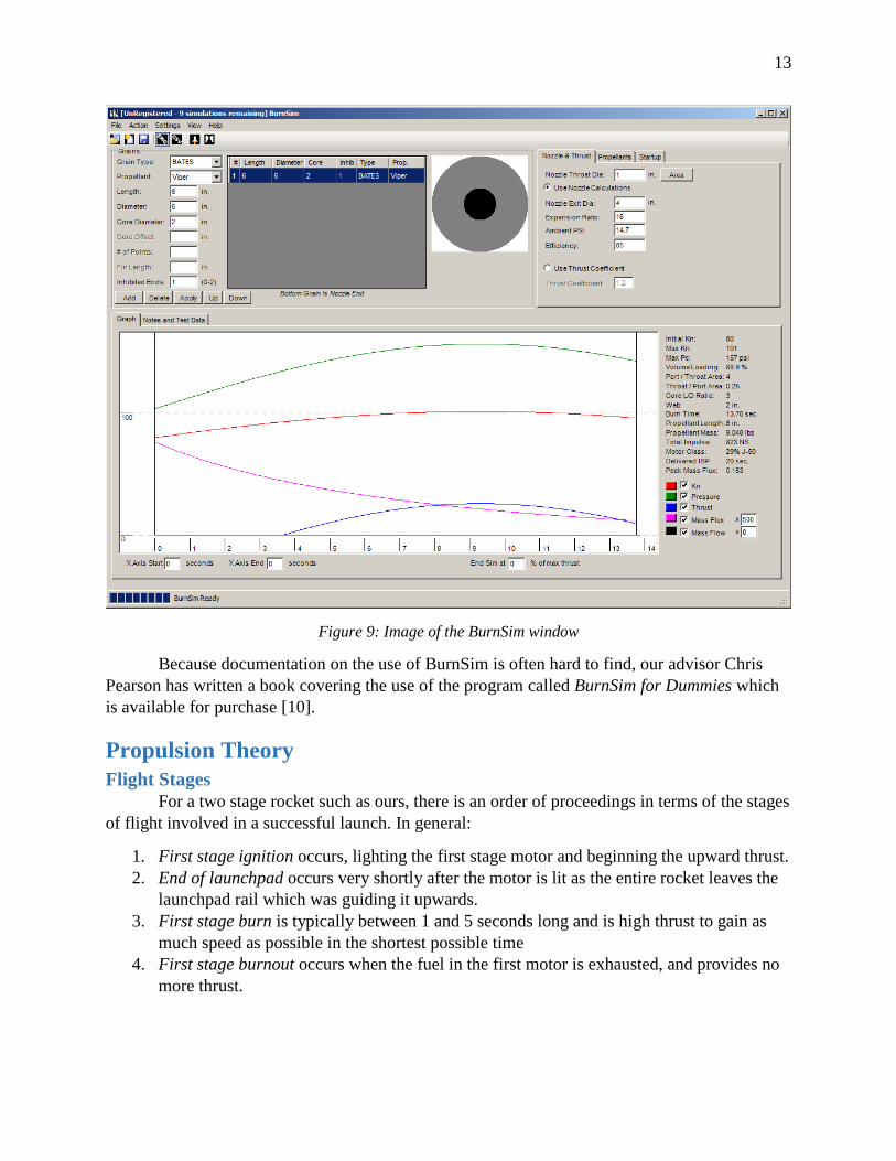
BurnSim
BurnSim is a tool used to model the combustion of fuel grains within a specific
motor/nozzle configuration. By specifying a fuel grain size and shape, the nozzle geometry, and
a few other key variables, BurnSim will output a theoretical thrust curve including values for
thrust, chamber pressure, and burn time [9]. The thrust curve is especially critical for
determining the overall flight performance of the rocket, since it indicates the amount of impulse
available to the rocket and thus how high it will travel. BurnSim is therefore a great tool for
designing and predicting the performance of new types of fuel grains. As mentioned before,
BurnSim can export its result files in .eng format to be imported into OpenRocket.
13
Figure 9: Image of the BurnSim window
Because documentation on the use of BurnSim is often hard to find, our advisor Chris
Pearson has written a book covering the use of the program called BurnSim for Dummies which
is available for purchase [10].
Propulsion Theory
Flight Stages
For a two stage rocket such as ours, there is an order of proceedings in terms of the stages
of flight involved in a successful launch. In general:
1. First stage ignition occurs, lighting the first stage motor and beginning the upward thrust.
2. End of launchpad occurs very shortly after the motor is lit as the entire rocket leaves the
launchpad rail which was guiding it upwards.
3. First stage burn is typically between 1 and 5 seconds long and is high thrust to gain as
much speed as possible in the shortest possible time
4. First stage burnout occurs when the fuel in the first motor is exhausted, and provides no
more thrust.
14
5. Stage separation occurs shortly after first stage burnout, and happens naturally if a
passive method such as drag separation occurs, where the stages pull apart from drag
once there is no first stage thrust occurring.
6. First stage recovery deployment may happen concurrently with stage separation or
shortly thereafter.
7. Second stage ignition will typically follow a 1 or 2 second delay after first stage burnout
to allow the stages to sufficiently separate in the air before igniting.
8. Second stage burn is usually longer, typically greater than 4 seconds for applications such
as ours. It has a lower average thrust but provides plenty of impulse due to its long burn
time.
9. Second stage burnout occurs as the second motor’s fuel is exhausted.
10. Coast occurs when the second stage is no longer under powered flight, and is simply
drifting upwards towards is max altitude. The rocket spends the majority of its upwards
flight time coasting.
11. Apogee is reached when the rocket’s upwards velocity is zero – or alternatively, when it
is at its highest point.
12. Drogue parachute release occurs at or shortly after apogee. This small parachute limits
the terminal velocity of the second stage without making it take many minutes to fall
back to the ground.
13. Primary parachute release occurs at a predefined low altitude during the descent and
marks the release of the much larger primary second stage chute.
14. Touchdown is the final step, as the second stage reaches the earth.
These proceedings are easy to visualize with a well-constructed OpenRocket simulation, as the
result plots mark out important flight points for the user.
Total and Specific Impulse
Total impulse is one of the primary measures of a motor’s performance along with values
for average and maximum thrust. It is defined as the integral of the motor’s thrust over the time it
acts [11]:
𝐼𝑡 = ∫ 𝐹 𝑑𝑡𝑡
𝑡𝑜
A motor that provides a constant 1000N of thrust for 1 second has a total impulse of 1000Ns.
Likewise, a motor that produces 100N of thrust for 10 seconds also provides 1000Ns of total
impulse. This is useful because total impulse is a sort of measure of the change in magnitude of
the linear momentum vector of an object – two motors providing the same total impulse cause
the same change in linear momentum, but act over different time intervals. Calculating the total
impulse from thrust curve data is just a matter of measuring the area under the thrust curve. The
total impulse is the method by which motors are classified. Three such classifications are shown
in the following table:
15
Class Total Impulse [N-s]
M 5,120 – 10,200
N 10,200 – 20,500
O 20,500 – 41,000
Table 1: Sample of motor classes and their defining total impulse values
Another measure sometimes used in rocketry is specific delivered impulse [11]:
𝐼𝑠𝑝 = 𝐼𝑡/(𝑔 ∙ 𝑚𝑓𝑢𝑒𝑙)
Dividing the total impulse by the weight of the fuel yields the amount of impulse delivered by
the motor per unit mass of fuel being carried. Specific impulse is a useful measure of fuel
efficiency similar to comparing two cars on the basis of miles per gallon. The higher the specific
impulse, the lower the propellant flow rate required for a given thrust, and the less propellant
needed for a given delta-v [12].
Stability
Stability refers to the degree to which the rocket will stay on its intended course. Two key
concepts involved in rocket stability are the center of gravity or CG and the center of pressure or
CP. The CG is defined as the average location of the weight of any object. The CP is the location
where the resultant force of aerodynamic pressure acts. There are several primary forces acting
on the rocket. The force of gravity pulls down towards the earth and acts through the CP. The
thrust generated by the motor acts along the angle of attack 𝛼 through the CG. Wind forces and
generated lift from the fins act through the CP.
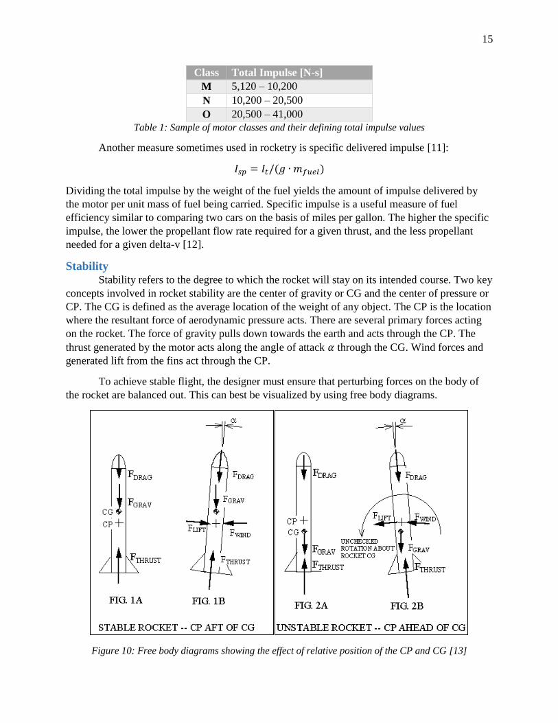
To achieve stable flight, the designer must ensure that perturbing forces on the body of
the rocket are balanced out. This can best be visualized by using free body diagrams.
Figure 10: Free body diagrams showing the effect of relative position of the CP and CG [13]
16
As the Figure 10 shows, the stability of the rocket is dependent on the location of the CP relative
to the CG. For stable flight, the CP must remain aft of the CG [13]. This ensures that when a
perturbing force (e.g. wind) causes a change in angle of attack, the resulting lift generated acts in
opposition to the perturbing force. This cancels out the moment about the CG that the wind
causes and prevents the rocket from tumbling.
The degree of stability is measured in calibers, which measures the distance separating
the CP and CG. One caliber equals one body diameter, so if a 6 inch diameter rocket had a CP aft
of the CG by 3 inches, it would have a stability of 0.5 calibers. Negative numbers indicate that
the CP is ahead of the CG. The ideal amount of stability to have is something around 0.75 to 1.5
calibers. This is because excessive levels of stability lead to a phenomenon called “weather
cocking”, which is the principle by which weather vanes work (rotating to face into the wind).
One may notice that in Figure 10 the stable rocket actually rotates towards the wind to a slight
degree, which is counterintuitive at first glance. That effect becomes larger as the rocket
becomes more and more stable. For calibers greater than around 2, the torque generated is so
large that the rocket will rotate to align itself with any perturbing wind force. This can lead to the
rocket drifting off course, essentially being pushed around at will by the air current. This
phenomenon can be especially dangerous for smaller amateur rockets, as their lower thrust
means that the rocket is more easily blown far off course by weather cocking.
It should be noted that during flight the mass is redistributed throughout the rocket, as
fuel at the bottom of the stage is consumed. As the fuel burns, the CG moves upward because
less mass is concentrated at the back of the rocket. This means that the rocket should become
more stable as it travels, an effect that can be visualized using OpenRocket.
Nozzle Theory
The nozzle is vitally important for achieving high levels of thrust from the combustion
process. The equation for thrust is given on page 20 [5]:
𝑇 = 𝑣𝑒�̇� + (𝑃𝑒 − 𝑃𝑎𝑡𝑚)𝐴𝑡
The first term provides the vast majority of the thrust, so it is apparent that maximizing 𝑣𝑒 is
crucial to increasing thrust. The nozzle’s converging-diverging shape allows the exhaust gasses
to reach supersonic speeds and greatly improves the efficiency of the motor.
In a nozzle, it is desirable to achieve an isentropic flow condition within both for analysis
and real world performance considerations. Isentropic flow is considered to be flow that is
dependent only upon cross-sectional area. Achieving a nearly isentropic nozzle necessitates
frictionless and adiabatic flow. Therefore, it is necessary to minimize frictional effects, flow
disturbances, and conditions that can lead to shock losses. To achieve this, nozzles are smoothly
contoured with shallow angles, and won’t work as intended if they are warped, ablated, or
damaged [14].
The stagnation properties for isentropic flows follow familiar forms seen in
Thermodynamics courses:
17
𝑇𝑜
𝑇= (
𝑃𝑜
𝑃)
𝛾𝛾−1
= (𝜌𝑜
𝜌)
𝛾−1
where the “o” subscript here denotes a stagnation value. With manipulation using relations
between Mach number and stagnation properties, the stagnation density and stagnation pressure
ratios can be constructed [14]:
𝑃𝑜
𝑃= (1 +
𝛾 + 1
2𝑀2)
𝛾𝛾−1
𝜌𝑜
𝜌= (1 +
𝛾 − 1
2𝑀2)
1𝛾−1
It is convenient that the stagnation conditions are equivalent to the conditions inside the
combustion chamber, since the flow velocity is considered zero inside.
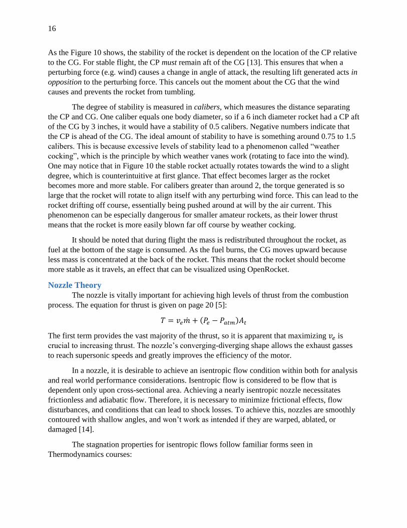
With more manipulation using mass conservation and thermodynamics, an interesting
and useful plot can be generated of the area ratio 𝐴/𝐴∗ versus the Mach number [14][15].
𝐴
𝐴∗=
1
𝑀(
1 +𝛾 − 1
2 𝑀2
1 +𝛾 − 1
2
)
𝛾+12(𝛾−1)
Figure 11: Area ratio versus Mach number in the nozzle, showing the necessity of the diverging section to
achieve high exhaust velocities
18
As shown, when the area ratio is 1, meaning the area of the point in the nozzle is equal to that of
the critical choked flow area in the throat 𝐴∗, the Mach number of the gas is also equal to 1,
meaning it is equal to the speed of sound. The interesting result is that to achieve Mach numbers
greater than 1 on this plot, the area ratio beyond the throat must be greater than one. This result
shows the necessity of the diverging section of the nozzle – without it, the Mach number of the
gas could never be more than 1, and the motor would produce little thrust [14].
Equations
There are several important equations used to calculate various values about the
propulsion systems of a rocket.
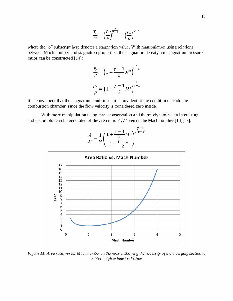
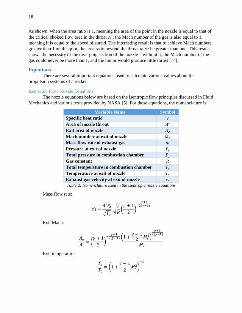
Isentropic Flow Nozzle Equations
The nozzle equations below are based on the isentropic flow principles discussed in Fluid
Mechanics and various texts provided by NASA [5]. For these equations, the nomenclature is:
Variable Name Symbol
Specific heat ratio 𝛾
Area of nozzle throat 𝐴∗
Exit area of nozzle 𝐴𝑒
Mach number at exit of nozzle 𝑀𝑒
Mass flow rate of exhaust gas �̇�
Pressure at exit of nozzle 𝑃𝑒
Total pressure in combustion chamber 𝑃𝑜
Gas constant 𝑅
Total temperature in combustion chamber 𝑇𝑜
Temperature at exit of nozzle 𝑇𝑒
Exhaust gas velocity at exit of nozzle 𝑣𝑒
Table 2: Nomenclature used in the isentropic nozzle equations
Mass flow rate:
�̇� =𝐴∗𝑃𝑜
√𝑇𝑜
√𝛾
𝑅(
𝛾 + 1
2)
−𝛾+1
2(𝛾−1)
Exit Mach:
𝐴𝑒
𝐴∗= (
𝛾 + 1
2)
−𝛾+1
2(𝛾−1) (1 +𝛾 − 1
2𝑀𝑒
2)
𝛾+12(𝛾−1)
𝑀𝑒
Exit temperature:
𝑇𝑒
𝑇𝑡= (1 +
𝛾 − 1
2𝑀𝑒
2)−1
19
Exit pressure:
𝑃𝑒
𝑃𝑜= (1 +
𝛾 − 1
2𝑀𝑒
2)
−𝛾𝛾−1
Exit velocity:
𝑣𝑒 = √2𝑇𝑜 (𝑅
𝑀) (
𝛾
𝛾 − 1) (1 − (
𝑃𝑒
𝑃𝑜)
𝛾−1𝛾
)
𝑣𝑒 = 𝑀𝑒√𝛾𝑅𝑇𝑒
Thermodynamic Properties for Gas Mixtures
Thermodynamic properties such as the specific heat ratio of combustion products can be
found using taking the reaction equation and finding the equivalent specific heats of the gas
phase combustion products (ignoring solid combustion products).
𝐶𝑝𝑐𝑝= 𝑦𝑔𝑎𝑠1𝐶𝑝𝑔𝑎𝑠1
+ 𝑦𝑔𝑎𝑠2𝐶𝑝𝑔𝑎𝑠2…
𝐶𝑣𝑐𝑝= 𝑦𝑔𝑎𝑠1𝐶𝑣𝑔𝑎𝑠1
+ 𝑦𝑔𝑎𝑠2𝐶𝑣𝑔𝑎𝑠2…
𝛾 =𝐶𝑝𝑐𝑝
𝐶𝑣𝑐𝑝
For these equations, 𝐶𝑝𝑐𝑝 is the constant pressure specific heat for the combustion products, and
𝐶𝑣𝑐𝑝 is the constant volume specific heat for the combustion products. 𝑦𝑥 is the mole fraction of
gas 𝑥 in the combustion exhaust reaction.
Determining Combustion Chamber Pressure
The combustion chamber pressure, which is required in several other equations shown,
can be calculated using the following complex relationship [16]:
𝑃𝑜 = (𝐾𝑛
𝐴
𝛼𝜌𝑝𝐶∗)
11−𝑛
Here 𝐾𝑛 is the ratio of propellant burn area to nozzle throat area 𝐴𝑏/𝐴𝑡, 𝐴 is an empirical burn
rate coefficient, 𝑛 is the burn rate pressure coefficient (somewhere near 0.3 to 0.5 for AP
propellants), 𝜌𝑝 is the solid density of the propellant, 𝐶∗ is the characteristic velocity of the
reaction (described below), and 𝛼 = 1,000,000 is a conversion factor from 𝑀𝑃𝑎 to 𝑃𝑎 that may
or may not be needed depending on the units that 𝐴 comes in. Typically, we are most interested
in 𝑃𝑜𝑚𝑎𝑥 because that is where the maximum internal stresses occur. 𝑃𝑜𝑚𝑎𝑥
occurs when the area
of burning 𝐴𝑏 is the highest [16].
20
𝐾𝑛 =𝐴𝑏
𝐴𝑡
Calculating 𝐴𝑏 is tricky, but well defined for BATES grains. For each grain, out of the total of 𝑁
grains in the chamber, the following picture can be drawn, where 𝑑 and 𝐿 define the burn surface
after the next time increment:
Figure 12: Schematic of the burning progression of a BATES grain [16]
Initially the grain has inner diameter 𝑑𝑜 and length 𝐿𝑜. Between ignition and the first time
increment, the surface of the grain is consumed in both the 𝑑 and the 𝐿 directions. The rate at
which each surface decays is the linear surface regression 𝑥. As the grain burns, two 𝑥-sized
units of 𝐿 are lost and two 𝑥-sized units of 𝑑 are gained with every time step. So, for any
instantaneous time step, 𝐴𝑏 is:
𝐴𝑏 = 𝑁 (1
2𝜋(𝐷2 − 𝑑2) + 𝜋𝐿𝑑)
𝑑 = 𝑑𝑜 + 2𝑥, 𝑎𝑛𝑑 𝐿 = 𝐿𝑜 − 2𝑥
Substituting the above expressions for 𝑑 and 𝐿 into the equation for 𝐴𝑏 gives an expression for
burn surface area with respect to linear surface regression 𝑥. The maximum of 𝐴𝑏 can be found
by setting its derivative equal to zero:
𝑑𝐴𝑏
𝑑𝑥= 0
Which gives the general solution for the 𝑥 value that maximizes 𝐴𝑏 (for BATES grains only):
𝑥 =1
6(𝐿𝑜 − 2𝑑𝑜)
Plugging this value for 𝑥 back into the expression for 𝐴𝑏 gives the value for the maximum burn
surface area, which can then be used to find 𝐾𝑛 (note that a complete demonstration is shown in
the Example Calculation section on page 21) [16].
Going back to our 𝑃𝑜 equation, 𝐶∗ is the characteristic exhaust velocity, with units of L/T.
𝐶∗ = √𝑅𝑇′
𝑀𝛾(
𝛾 + 1
2)
𝛾+1𝛾−1
21
Here, 𝑅 is the universal gas constant, 𝑀 is the molar mass of the exhaust gas mixture (which can
be found in the same fashion as the specific heats above), and 𝑇′ is the ideal combustion
temperature for the fuel.
Nozzle Area Ratios
To design the nozzle, the most critical parameter is the area ratio 𝐴𝑒/𝐴∗. Once the
combustion chamber pressure is known, the following relation can be used assuming the pressure
at the nozzle exit 𝑃𝑒 is atmospheric [14].
𝐴∗
𝐴𝑒= (
𝛾 + 1
2)
1𝛾−1
(𝑃𝑒
𝑃𝑜)
1𝛾
√(𝛾 + 1
𝛾 − 1) (1 − (
𝑃𝑒
𝑃𝑜)
𝛾−1𝛾
)
This equation is hard to work with, but it helps to simplify all the 𝛾 terms and the pressure ratio
𝑃𝑒/𝑃𝑜 terms first. Note that if 𝑃𝑜 is found using the equation on page 18, it may contain an
unknown 𝐴𝑡 term if the desired nozzle throat is not yet determined. It’s fine to leave 𝑃𝑜 in terms
of 𝐴𝑡 at this point if a value for 𝐴𝑡 is not yet known. For any 𝐴𝑡 chosen, this equation can be
used to solve for the required expansion ratio to achieve choked flow at the throat. It should be
noted that changing 𝐴𝑡 changes the chamber pressure, and small enough throats will cause the
stress inside the motor case to become too high. In addition, not all expansion ratios are
reasonable because they produce a 𝐷𝑒 which is not realistic. One can easily plot 𝐴𝑒/𝐴∗ , 𝐷𝑒, and
𝑃𝑜 versus 𝐴𝑡 to come up with a good design. An example problem demonstrating this procedure
starts on page 22.
Thrust
The thrust produced by a rocket engine is related to the exit velocity and flow rate of the
exhaust gas (𝑣𝑒 and �̇�), the pressure difference between the nozzle exit and the atmosphere 𝑃𝑒 −𝑃𝑎𝑡𝑚, and the exit area of the nozzle 𝐴𝑒 [5].
𝑇 = 𝑣𝑒�̇� + (𝑃𝑒 − 𝑃𝑎𝑡𝑚)𝐴𝑒
In practice, the 𝑃𝑒 − 𝑃𝑎𝑡𝑚 term is usually close to zero, and is exactly equal to zero if an ideal
expansion ratio in the nozzle is achieved. The first term therefore dominates the generated thrust.
Tsiolkovsky Rocket Equation
The Tsiolkovsky rocket equation is an important and elegant equation in rocketry. The
equation relates the delta-v (the maximum change of velocity of the rocket if no other external
forces act) with the effective exhaust velocity and the initial and final mass of a rocket (or other
reaction engine) [17].
∆𝑣 = 𝑣𝑒 ln𝑚𝑜
𝑚1
22
Example Calculation
For our custom motor and propellant, we can use the above equations to determine the
specific heat ratio of the combustion products, an expression for the internal combustion
chamber pressure as a function of nozzle throat area, and a working nozzle design.
Figure 13: Example calculation for the combustion chamber pressure
23
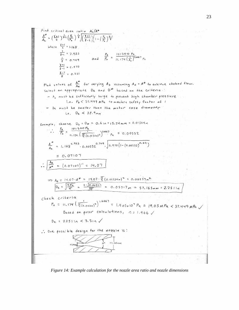
Figure 14: Example calculation for the nozzle area ratio and nozzle dimensions
24
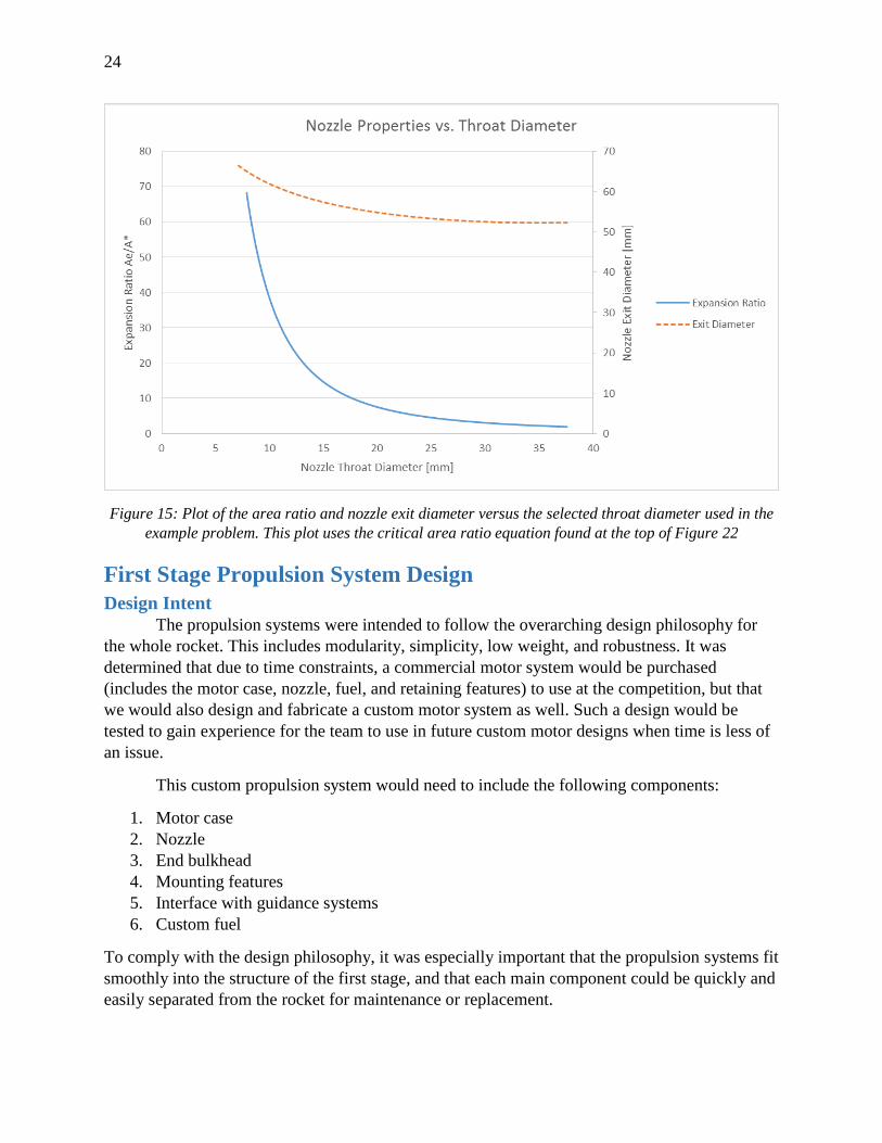
Figure 15: Plot of the area ratio and nozzle exit diameter versus the selected throat diameter used in the
example problem. This plot uses the critical area ratio equation found at the top of Figure 22
First Stage Propulsion System Design
Design Intent
The propulsion systems were intended to follow the overarching design philosophy for
the whole rocket. This includes modularity, simplicity, low weight, and robustness. It was
determined that due to time constraints, a commercial motor system would be purchased
(includes the motor case, nozzle, fuel, and retaining features) to use at the competition, but that
we would also design and fabricate a custom motor system as well. Such a design would be
tested to gain experience for the team to use in future custom motor designs when time is less of
an issue.
This custom propulsion system would need to include the following components:
1. Motor case
2. Nozzle
3. End bulkhead
4. Mounting features
5. Interface with guidance systems
6. Custom fuel
To comply with the design philosophy, it was especially important that the propulsion systems fit
smoothly into the structure of the first stage, and that each main component could be quickly and
easily separated from the rocket for maintenance or replacement.
25
Motor Case
The motor case is simply a cylindrical tube designed to contain the propellant grains and
to withstand the intense pressure and temperature during burning. Failure of the case almost
certainly implies catastrophic failure for the entire rocket, so care must be taken during design if
a custom motor case is desired.
The motor case must perform a few functions besides simply being there to contain the
reaction. The list of requirements for the custom motor case were brainstormed and listed as
such:
1. Provide a tight-fitting chamber to fit the phenolic liner and propellant grains
2. Provide a means to secure a cap or bulkhead at the fore end to seal off the combustion
from damaging forward components
3. Provide a means to insert a nozzle
To satisfy requirement 1, it is important to ensure the tube complies with the standard
rocket class sizes. The first stage was to be a 98mm class motor based on our OpenRocket
simulations, which helpfully sets the diameter dimensions of all other components to standard
values [18].
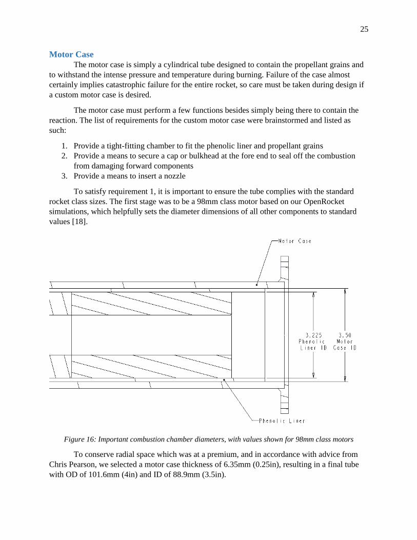
Figure 16: Important combustion chamber diameters, with values shown for 98mm class motors
To conserve radial space which was at a premium, and in accordance with advice from
Chris Pearson, we selected a motor case thickness of 6.35mm (0.25in), resulting in a final tube
with OD of 101.6mm (4in) and ID of 88.9mm (3.5in).
26
The details of satisfying requirements 2 and 3 can be found in the End Bulkhead section
on pages 34-36 and the Nozzle section on pages 30-32 respectively.
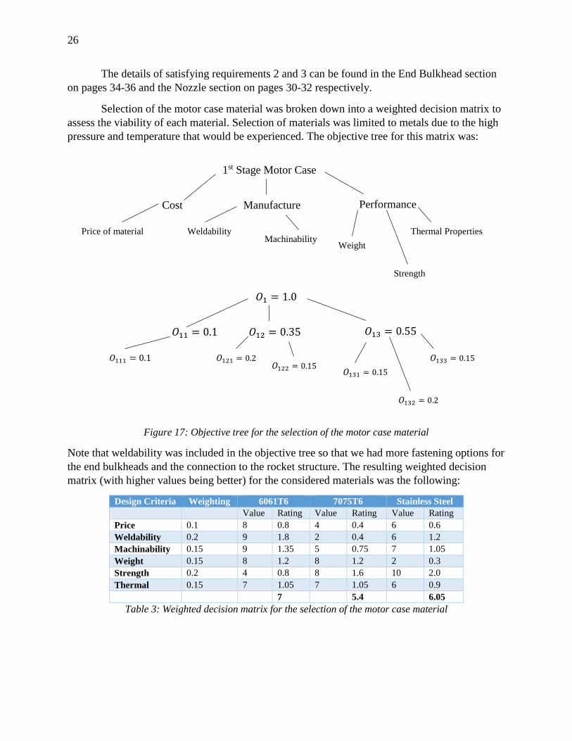
Selection of the motor case material was broken down into a weighted decision matrix to
assess the viability of each material. Selection of materials was limited to metals due to the high
pressure and temperature that would be experienced. The objective tree for this matrix was:
Figure 17: Objective tree for the selection of the motor case material
Note that weldability was included in the objective tree so that we had more fastening options for
the end bulkheads and the connection to the rocket structure. The resulting weighted decision
matrix (with higher values being better) for the considered materials was the following:
Design Criteria Weighting 6061T6 7075T6 Stainless Steel
Value Rating Value Rating Value Rating
Price 0.1 8 0.8 4 0.4 6 0.6
Weldability 0.2 9 1.8 2 0.4 6 1.2
Machinability 0.15 9 1.35 5 0.75 7 1.05
Weight 0.15 8 1.2 8 1.2 2 0.3
Strength 0.2 4 0.8 8 1.6 10 2.0
Thermal 0.15 7 1.05 7 1.05 6 0.9
7 5.4 6.05
Table 3: Weighted decision matrix for the selection of the motor case material
1st Stage Motor Case
Cost Performance
Price of material
Manufacture
Weldability Machinability
Weight
Strength
Thermal Properties
𝑂1 = 1.0
𝑂11 = 0.1 𝑂13 = 0.55
𝑂111 = 0.1
𝑂12 = 0.35
𝑂121 = 0.2 𝑂122 = 0.15
𝑂131 = 0.15
𝑂132 = 0.2
𝑂133 = 0.15
27
As determined from the weighted decision matrix, 6061T6 aluminum was the best choice
material for the motor case, and is also commonly used in similar applications.
Next, it was necessary to ensure the motor case was robust enough to survive the high
internal pressures it would see. Due to its function and shape, the motor case is well suited to
simple pressure vessel stress analysis. The ratio of wall thickness to radius is:
𝑡
𝑟𝑜=
6.35𝑚𝑚
50.8𝑚𝑚= 0.125 >
1
10
As a result, we cannot apply a thin wall approximation and must use the full equations for
tangential, radial, and longitudinal pressure vessel stress [19]:
𝜎𝑡 =𝑃𝑖𝑟𝑖
2 − 𝑃𝑜𝑟𝑜2 − 𝑟𝑖
2𝑟𝑜2(𝑃𝑜 − 𝑃𝑖)/𝑟2
𝑟𝑜2 − 𝑟𝑖
2
𝜎𝑟 =𝑃𝑖𝑟𝑖
2 − 𝑃𝑜𝑟𝑜2 + 𝑟𝑖
2𝑟𝑜2(𝑃𝑜 − 𝑃𝑖)/𝑟2
𝑟𝑜2 − 𝑟𝑖
2
𝜎𝑙 =𝑃𝑖𝑟𝑖
2
𝑟𝑜2 − 𝑟𝑖
2
The details of the resulting calculations were done by hand, assuming two things:
1. The worst von-Mises stress occurs at the inside wall of the case [19]
2. The worst internal pressure is not known, but is not expected to be worse than 6.895MPa
(1000psia) according to BurnSim predictions for our type of fuel
28
Figure 18: Calculation to predict the strength of the motor case as designed
29
As a result, it was determined that the motor case as designed would have a factor of safety
greater than 5, which is considered very robust. The maximum internal pressure such a vessel
could support without yield is ~37MPa (5366psia).
One final consideration to make is the co-dependence of burn rate and chamber pressure.
In general, the burn rate follows a power law of the form [20]:
�̇� = 𝐴 ∙ 𝑃𝑛
Where 𝐴 is empirically determined for the type of fuel, 𝑃 is the chamber pressure, and 𝑛 is the
pressure exponent. If the burn rate is allowed to accelerate without bound, often due to pressure
exponent 𝑛 being greater than 1, a runaway reaction can occur. The burn rate causes an increase
in pressure, which causes an increase in burn rate, and the process proceeds exponentially until
the case is blown apart. The choice of additives in the fuel and the grain geometry should be
carefully selected to protect against such an event.
Nozzle
The nozzle is retained to the aft end motor case in some fashion to prevent it from being
blown out the back of the rocket due to the chamber pressure. The nozzle sees the highest
thermal loadings in the throat of the converging-diverging section and is susceptible to thermal
cracking and ablation as discussed previously. As a result, most high power rockets use special
materials to survive the flight. The highest end rockets, such as those used by NASA, use very
exotic ceramics or zinc alloys which are cast into highly optimized shapes.
Figure 19: Example cross section of a NASA cast nozzle [21]
30
Because they are cast, flanges with clearance holes can be easily (albeit expensively) added to
them to have a strong bolted or cap-screw type connection to the combustion chamber.
In our case, such nozzles were looked in to but were quickly ruled out due to the extreme
cost and very long manufacturing lead times required to make an appropriate casting. Most
amateur rockets of the sizes we are working with instead use machined graphite or phenolic
nozzles which fit inside of the motor case ID.
Figure 20: Example machined graphite nozzles for amateur rockets [22]
As shown, these graphite nozzles usually have o-ring grooves machined into them which seal
inside the motor case and prevent exhaust gasses from leaking past.
As discussed, the geometry of the nozzle has a significant impact on its performance. The
exit to throat ratio 𝐴𝑒/𝐴∗ factors into the resulting exit Mach number of the exhaust products.
This therefore affects the resulting thrust, since the Mach number is related to the exhaust gas
velocity, and the exhaust gas velocity determines the thrust [14]. This relation is shown in the
Equations section. In addition, the cone half angles of the converging and diverging sections
impact the isentropic efficiency of the nozzle, though the angle of the converging section is
shown to have a negligible effect as long as its shape is reasonable [3].
31
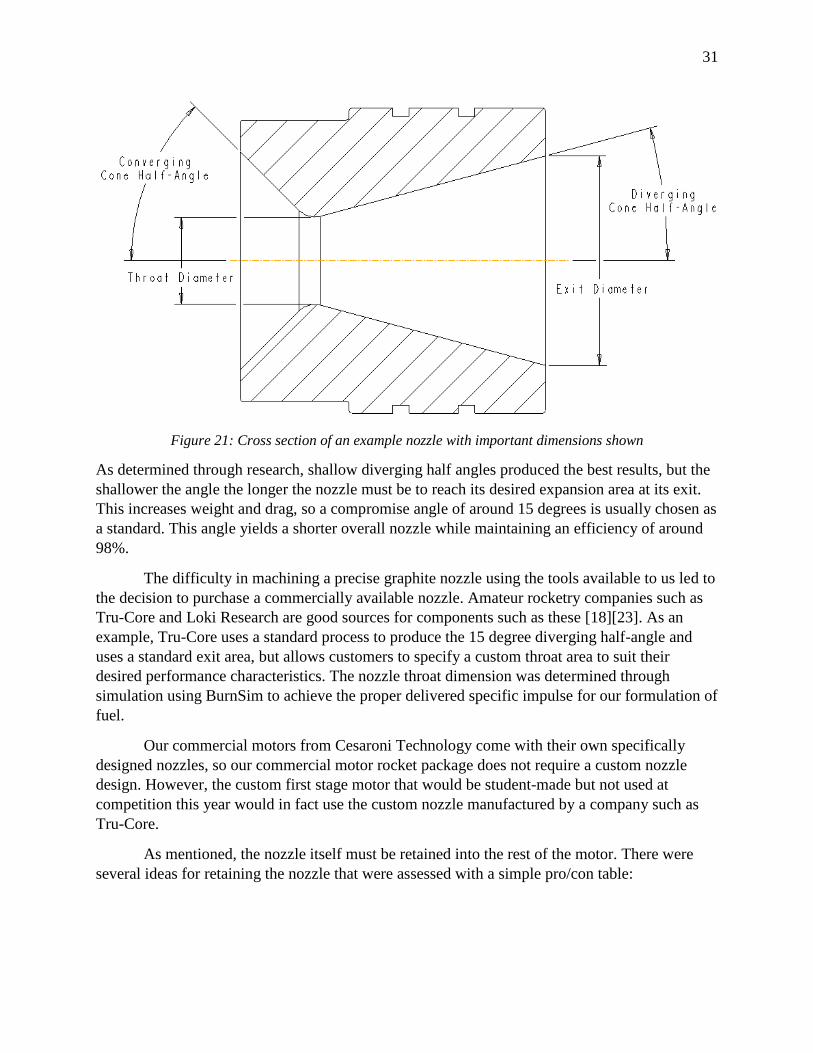
Figure 21: Cross section of an example nozzle with important dimensions shown
As determined through research, shallow diverging half angles produced the best results, but the
shallower the angle the longer the nozzle must be to reach its desired expansion area at its exit.
This increases weight and drag, so a compromise angle of around 15 degrees is usually chosen as
a standard. This angle yields a shorter overall nozzle while maintaining an efficiency of around
98%.
The difficulty in machining a precise graphite nozzle using the tools available to us led to
the decision to purchase a commercially available nozzle. Amateur rocketry companies such as
Tru-Core and Loki Research are good sources for components such as these [18][23]. As an
example, Tru-Core uses a standard process to produce the 15 degree diverging half-angle and
uses a standard exit area, but allows customers to specify a custom throat area to suit their
desired performance characteristics. The nozzle throat dimension was determined through
simulation using BurnSim to achieve the proper delivered specific impulse for our formulation of
fuel.
Our commercial motors from Cesaroni Technology come with their own specifically
designed nozzles, so our commercial motor rocket package does not require a custom nozzle
design. However, the custom first stage motor that would be student-made but not used at
competition this year would in fact use the custom nozzle manufactured by a company such as
Tru-Core.
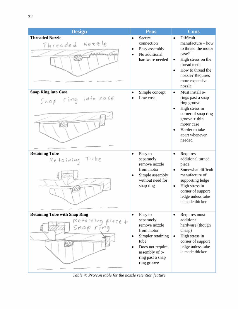
As mentioned, the nozzle itself must be retained into the rest of the motor. There were
several ideas for retaining the nozzle that were assessed with a simple pro/con table:
32
Design Pros Cons Threaded Nozzle
Secure
connection
Easy assembly
No additional
hardware needed
Difficult
manufacture – how
to thread the motor
case?
High stress on the
thread teeth
How to thread the
nozzle? Requires
more expensive
nozzle
Snap Ring into Case
Simple concept
Low cost
Must install o-
rings past a snap
ring groove
High stress in
corner of snap ring
groove + thin
motor case
Harder to take
apart whenever
needed
Retaining Tube
Easy to
separately
remove nozzle
from motor
Simple assembly
without need for
snap ring
Requires
additional turned
piece
Somewhat difficult
manufacture of
supporting ledge
High stress in
corner of support
ledge unless tube
is made thicker
Retaining Tube with Snap Ring
Easy to
separately
remove nozzle
from motor
Simpler retaining
tube
Does not require
assembly of o-
ring past a snap
ring groove
Requires most
additional
hardware (though
cheap)
High stress in
corner of support
ledge unless tube
is made thicker
Table 4: Pro/con table for the nozzle retention feature
33
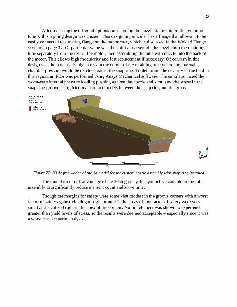
After assessing the different options for retaining the nozzle to the motor, the retaining
tube with snap ring design was chosen. This design in particular has a flange that allows it to be
easily connected to a mating flange on the motor case, which is discussed in the Welded Flange
section on page 37. Of particular value was the ability to assemble the nozzle into the retaining
tube separately from the rest of the motor, then assembling the tube with nozzle into the back of
the motor. This allows high modularity and fast replacement if necessary. Of concern in this
design was the potentially high stress in the corner of the retaining tube where the internal
chamber pressure would be reacted against the snap ring. To determine the severity of the load in
this region, an FEA was performed using Ansys Mechanical software. The simulation used the
worst-case internal pressure loading pushing against the nozzle and simulated the stress in the
snap ring groove using frictional contact models between the snap ring and the groove.
Figure 22: 30 degree wedge of the 3d model for the custom nozzle assembly with snap ring installed
The model used took advantage of the 30 degree cyclic symmetry available in the full
assembly to significantly reduce element count and solve time.
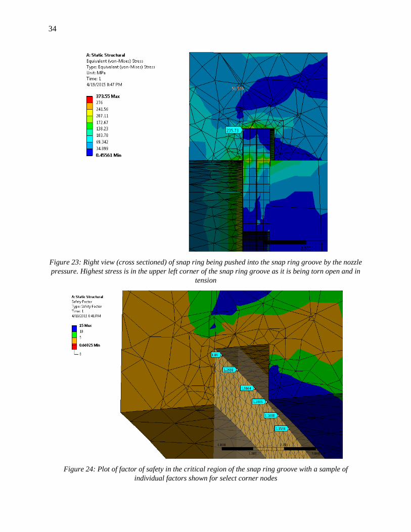
Though the margins for safety were somewhat modest in the groove corners with a worst
factor of safety against yielding of right around 1, the areas of low factor of safety were very
small and localized right in the apex of the corners. No full element was shown to experience
greater than yield levels of stress, so the results were deemed acceptable – especially since it was
a worst case scenario analysis.
34
Figure 23: Right view (cross sectioned) of snap ring being pushed into the snap ring groove by the nozzle
pressure. Highest stress is in the upper left corner of the snap ring groove as it is being torn open and in
tension
Figure 24: Plot of factor of safety in the critical region of the snap ring groove with a sample of
individual factors shown for select corner nodes
35
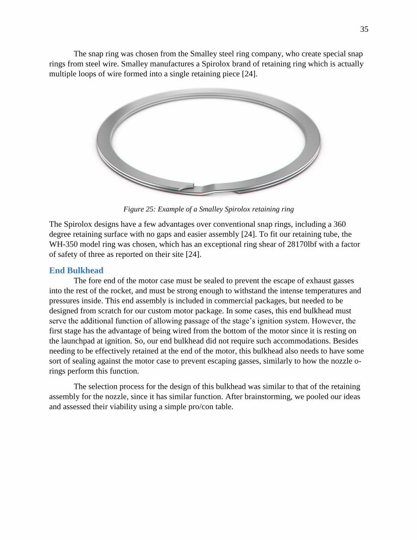
The snap ring was chosen from the Smalley steel ring company, who create special snap
rings from steel wire. Smalley manufactures a Spirolox brand of retaining ring which is actually
multiple loops of wire formed into a single retaining piece [24].
Figure 25: Example of a Smalley Spirolox retaining ring
The Spirolox designs have a few advantages over conventional snap rings, including a 360
degree retaining surface with no gaps and easier assembly [24]. To fit our retaining tube, the
WH-350 model ring was chosen, which has an exceptional ring shear of 28170lbf with a factor
of safety of three as reported on their site [24].
End Bulkhead
The fore end of the motor case must be sealed to prevent the escape of exhaust gasses
into the rest of the rocket, and must be strong enough to withstand the intense temperatures and
pressures inside. This end assembly is included in commercial packages, but needed to be
designed from scratch for our custom motor package. In some cases, this end bulkhead must
serve the additional function of allowing passage of the stage’s ignition system. However, the
first stage has the advantage of being wired from the bottom of the motor since it is resting on
the launchpad at ignition. So, our end bulkhead did not require such accommodations. Besides
needing to be effectively retained at the end of the motor, this bulkhead also needs to have some
sort of sealing against the motor case to prevent escaping gasses, similarly to how the nozzle o-
rings perform this function.
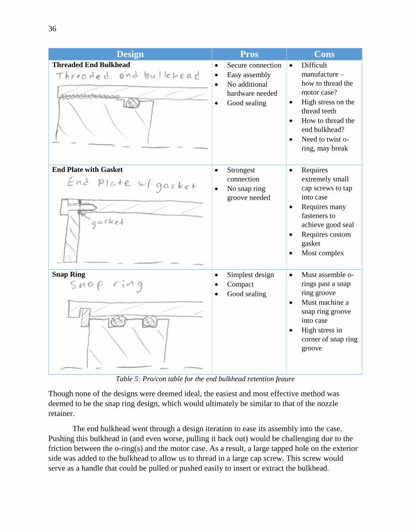
The selection process for the design of this bulkhead was similar to that of the retaining
assembly for the nozzle, since it has similar function. After brainstorming, we pooled our ideas
and assessed their viability using a simple pro/con table.
36
Design Pros Cons Threaded End Bulkhead
Secure connection
Easy assembly
No additional
hardware needed
Good sealing
Difficult
manufacture –
how to thread the
motor case?
High stress on the
thread teeth
How to thread the
end bulkhead?
Need to twist o-
ring, may break
End Plate with Gasket
Strongest
connection
No snap ring
groove needed
Requires
extremely small
cap screws to tap
into case
Requires many
fasteners to
achieve good seal
Requires custom
gasket
Most complex
Snap Ring
Simplest design
Compact
Good sealing
Must assemble o-
rings past a snap
ring groove
Must machine a
snap ring groove
into case
High stress in
corner of snap ring
groove
Table 5: Pro/con table for the end bulkhead retention feaure
Though none of the designs were deemed ideal, the easiest and most effective method was
deemed to be the snap ring design, which would ultimately be similar to that of the nozzle
retainer.
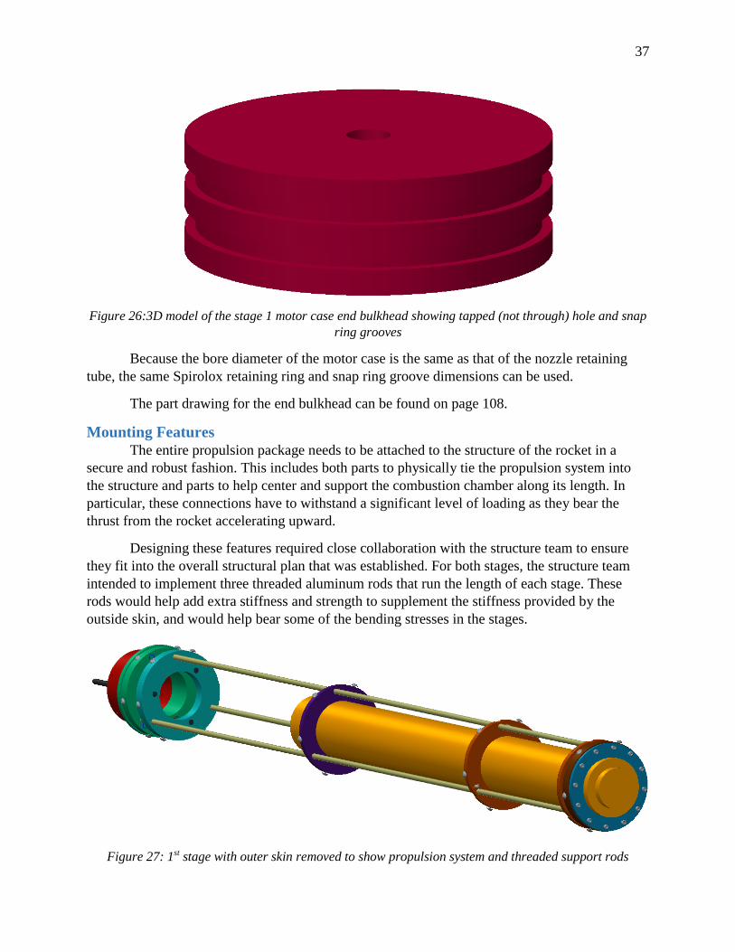
The end bulkhead went through a design iteration to ease its assembly into the case.
Pushing this bulkhead in (and even worse, pulling it back out) would be challenging due to the
friction between the o-ring(s) and the motor case. As a result, a large tapped hole on the exterior
side was added to the bulkhead to allow us to thread in a large cap screw. This screw would
serve as a handle that could be pulled or pushed easily to insert or extract the bulkhead.
37
Figure 26:3D model of the stage 1 motor case end bulkhead showing tapped (not through) hole and snap
ring grooves
Because the bore diameter of the motor case is the same as that of the nozzle retaining
tube, the same Spirolox retaining ring and snap ring groove dimensions can be used.
The part drawing for the end bulkhead can be found on page 108.
Mounting Features
The entire propulsion package needs to be attached to the structure of the rocket in a
secure and robust fashion. This includes both parts to physically tie the propulsion system into
the structure and parts to help center and support the combustion chamber along its length. In
particular, these connections have to withstand a significant level of loading as they bear the
thrust from the rocket accelerating upward.
Designing these features required close collaboration with the structure team to ensure
they fit into the overall structural plan that was established. For both stages, the structure team
intended to implement three threaded aluminum rods that run the length of each stage. These
rods would help add extra stiffness and strength to supplement the stiffness provided by the
outside skin, and would help bear some of the bending stresses in the stages.
Figure 27: 1st stage with outer skin removed to show propulsion system and threaded support rods
38
As shown, these rods run the length of the stage close to the ID of the skin to allow internal
clearance for the avionics, recovery, and propulsion components.
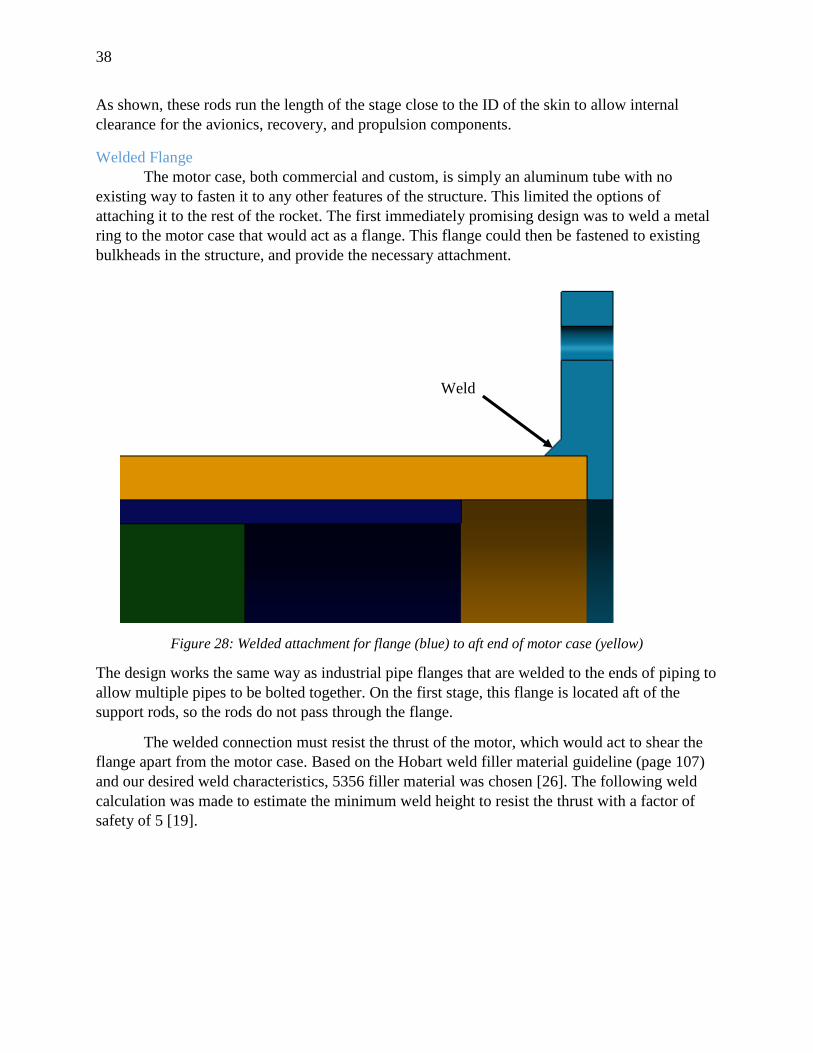
Welded Flange
The motor case, both commercial and custom, is simply an aluminum tube with no
existing way to fasten it to any other features of the structure. This limited the options of
attaching it to the rest of the rocket. The first immediately promising design was to weld a metal
ring to the motor case that would act as a flange. This flange could then be fastened to existing
bulkheads in the structure, and provide the necessary attachment.
Figure 28: Welded attachment for flange (blue) to aft end of motor case (yellow)
The design works the same way as industrial pipe flanges that are welded to the ends of piping to
allow multiple pipes to be bolted together. On the first stage, this flange is located aft of the
support rods, so the rods do not pass through the flange.
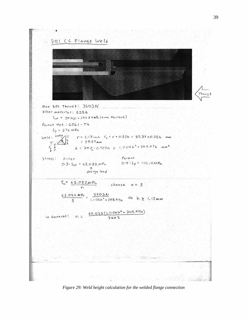
The welded connection must resist the thrust of the motor, which would act to shear the
flange apart from the motor case. Based on the Hobart weld filler material guideline (page 107)
and our desired weld characteristics, 5356 filler material was chosen [26]. The following weld
calculation was made to estimate the minimum weld height to resist the thrust with a factor of
safety of 5 [19].
Weld
39
Figure 29: Weld height calculation for the welded flange connection
40
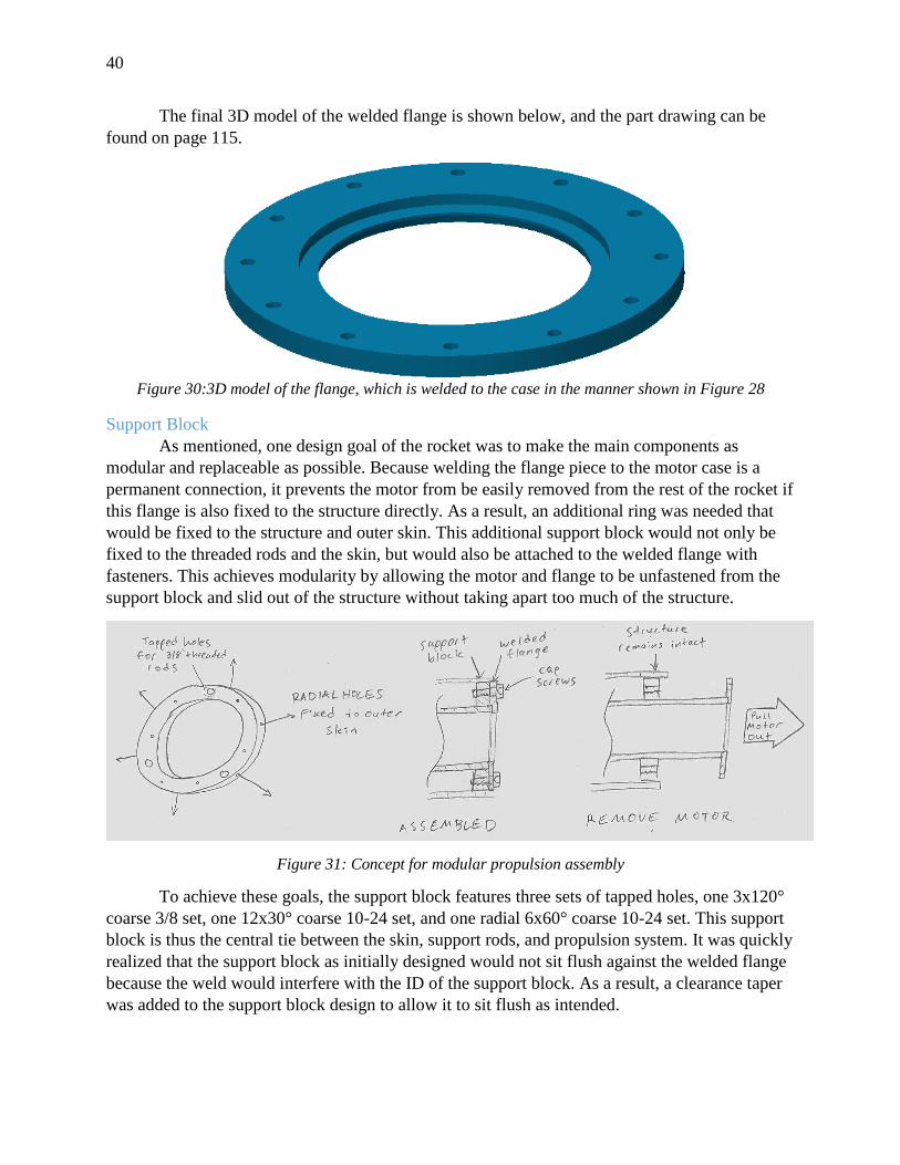
The final 3D model of the welded flange is shown below, and the part drawing can be
found on page 115.
Figure 30:3D model of the flange, which is welded to the case in the manner shown in Figure 28
Support Block
As mentioned, one design goal of the rocket was to make the main components as
modular and replaceable as possible. Because welding the flange piece to the motor case is a
permanent connection, it prevents the motor from be easily removed from the rest of the rocket if
this flange is also fixed to the structure directly. As a result, an additional ring was needed that
would be fixed to the structure and outer skin. This additional support block would not only be
fixed to the threaded rods and the skin, but would also be attached to the welded flange with
fasteners. This achieves modularity by allowing the motor and flange to be unfastened from the
support block and slid out of the structure without taking apart too much of the structure.
Figure 31: Concept for modular propulsion assembly
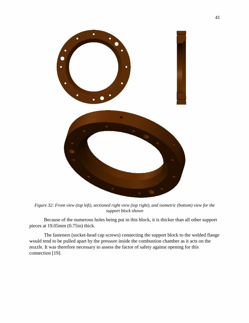
To achieve these goals, the support block features three sets of tapped holes, one 3x120°
coarse 3/8 set, one 12x30° coarse 10-24 set, and one radial 6x60° coarse 10-24 set. This support
block is thus the central tie between the skin, support rods, and propulsion system. It was quickly
realized that the support block as initially designed would not sit flush against the welded flange
because the weld would interfere with the ID of the support block. As a result, a clearance taper
was added to the support block design to allow it to sit flush as intended.
41
Figure 32: Front view (top left), sectioned right view (top right), and isometric (bottom) view for the
support block shown
Because of the numerous holes being put in this block, it is thicker than all other support
pieces at 19.05mm (0.75in) thick.
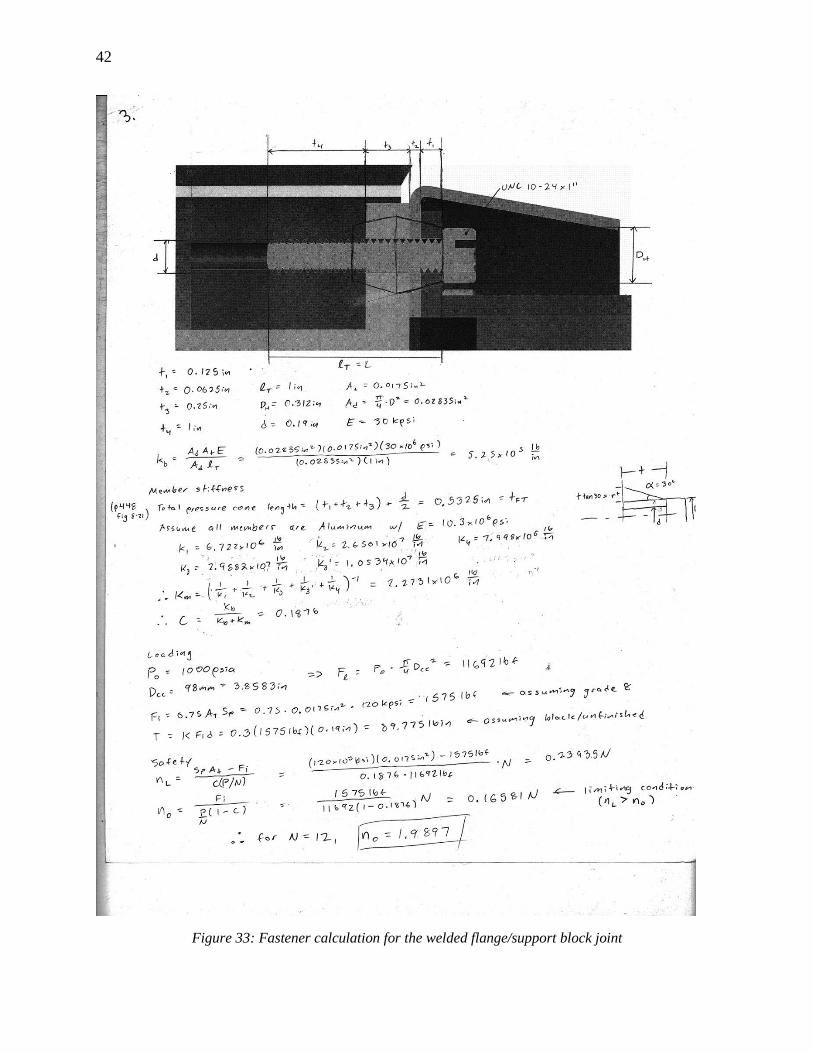
The fasteners (socket-head cap screws) connecting the support block to the welded flange
would tend to be pulled apart by the pressure inside the combustion chamber as it acts on the
nozzle. It was therefore necessary to assess the factor of safety against opening for this
connection [19].
42
Figure 33: Fastener calculation for the welded flange/support block joint

43
The limiting factor determining the failure of the joint was opening and not overloading of the
screws themselves. This factor of safety against opening was found to be almost 2 with 12 10-24
cap screws installed.
Centering Ring
The support block and flange pieces are located all the way at the back end of the rocket.
Without additional support, this means the motor case is cantilevered out by almost its entire
length. This means that while firing, the motor would be free to become misaligned with the axis
of travel of the rest of the rocket, and would be free to vibrate uncontrollably. To prevent this, an
additional ring was conceived to simply provide centering and support for the motor case
towards its end. This ring would have three clearance holes in it to allow the support rods to pass
through it, and would pilot the end of the motor case on its ID. The tolerancing on this pilot
surface needs to be very tight to allow the motor to snugly fit inside without any slop.
Figure 34: Centering ring (top image) shown supporting the front end of the motor on its ID (bottom
image) in the propulsion assembly
Interface with Guidance Systems
The rocket fins are located as far rearward as possible to move the center of pressure as
far aft as possible. This improves stability as described in the Stability section on page 14 [13].
44
However, this presents the problem of mounting the fins around the propulsion system, as they
occupy the same axial region on the rocket. Because the outer skin material is unweldable, the
fins needed to be attached to the internal structure through the outer skin in some manner.
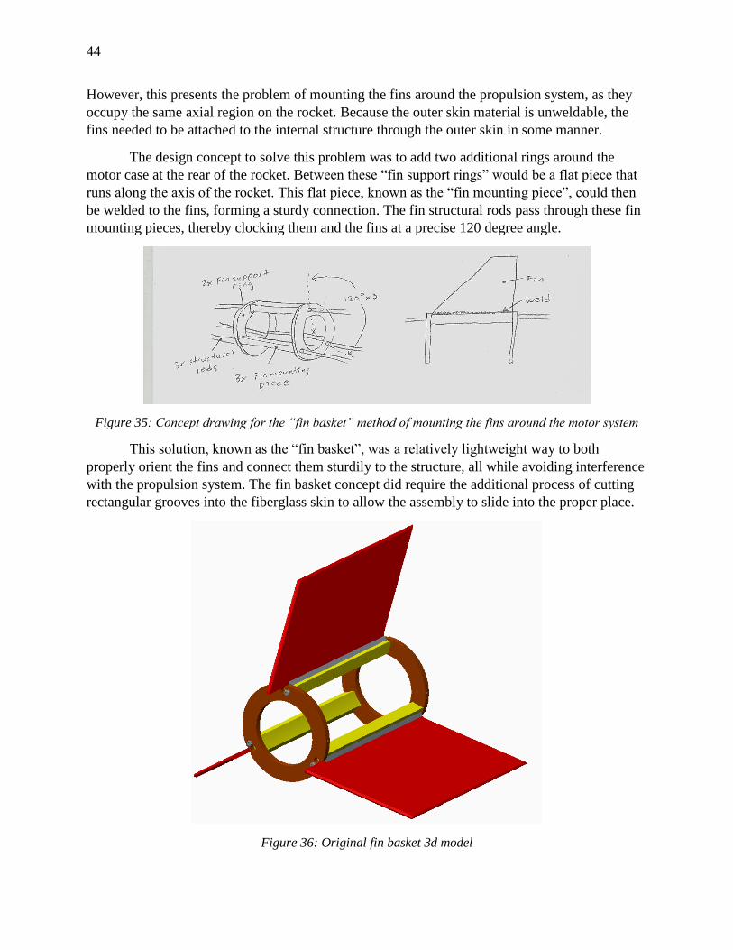
The design concept to solve this problem was to add two additional rings around the
motor case at the rear of the rocket. Between these “fin support rings” would be a flat piece that
runs along the axis of the rocket. This flat piece, known as the “fin mounting piece”, could then
be welded to the fins, forming a sturdy connection. The fin structural rods pass through these fin
mounting pieces, thereby clocking them and the fins at a precise 120 degree angle.
Figure 35: Concept drawing for the “fin basket” method of mounting the fins around the motor system
This solution, known as the “fin basket”, was a relatively lightweight way to both
properly orient the fins and connect them sturdily to the structure, all while avoiding interference
with the propulsion system. The fin basket concept did require the additional process of cutting
rectangular grooves into the fiberglass skin to allow the assembly to slide into the proper place.
Figure 36: Original fin basket 3d model
45
The fin basket has the added advantage of allowing the fins to overhang off of the fin mounting
pieces by some amount. This can be used to adjust the CP backwards in case additional stability
is desired.
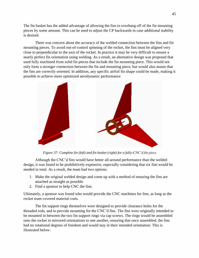
There was concern about the accuracy of the welded connection between the fins and fin
mounting pieces. To avoid out-of-control spinning of the rocket, the fins must be aligned very
close to perpendicular to the axis of the rocket. In practice it may be very difficult to ensure a
nearly perfect fin orientation using welding. As a result, an alternative design was proposed that
used fully machined from solid fin pieces that include the fin mounting piece. This would not
only form a stronger connection between the fin and mounting piece, but would also assure that
the fins are correctly oriented. In addition, any specific airfoil fin shape could be made, making it
possible to achieve more optimized aerodynamic performance
Figure 37: Complete fin (left) and fin basket (right) for a fully-CNC’d fin piece
Although the CNC’d fins would have better all-around performance than the welded
design, it was found to be prohibitively expensive, especially considering that six fins would be
needed in total. As a result, the team had two options:
1. Make the original welded design and come up with a method of ensuring the fins are
attached as straight as possible
2. Find a sponsor to help CNC the fins.
Ultimately, a sponsor was found who would provide the CNC machines for free, as long as the
rocket team covered material costs.
The fin support rings themselves were designed to provide clearance holes for the
threaded rods, and to provide mounting for the CNC’d fins. The fins were originally intended to
be mounted in between the two fin support rings via cap screws. The rings would be assembled
onto the rocket in mirrored orientations to one another, ensuring that once assembled, the fins
had no rotational degrees of freedom and would stay in their intended orientation. This is
illustrated below:
46
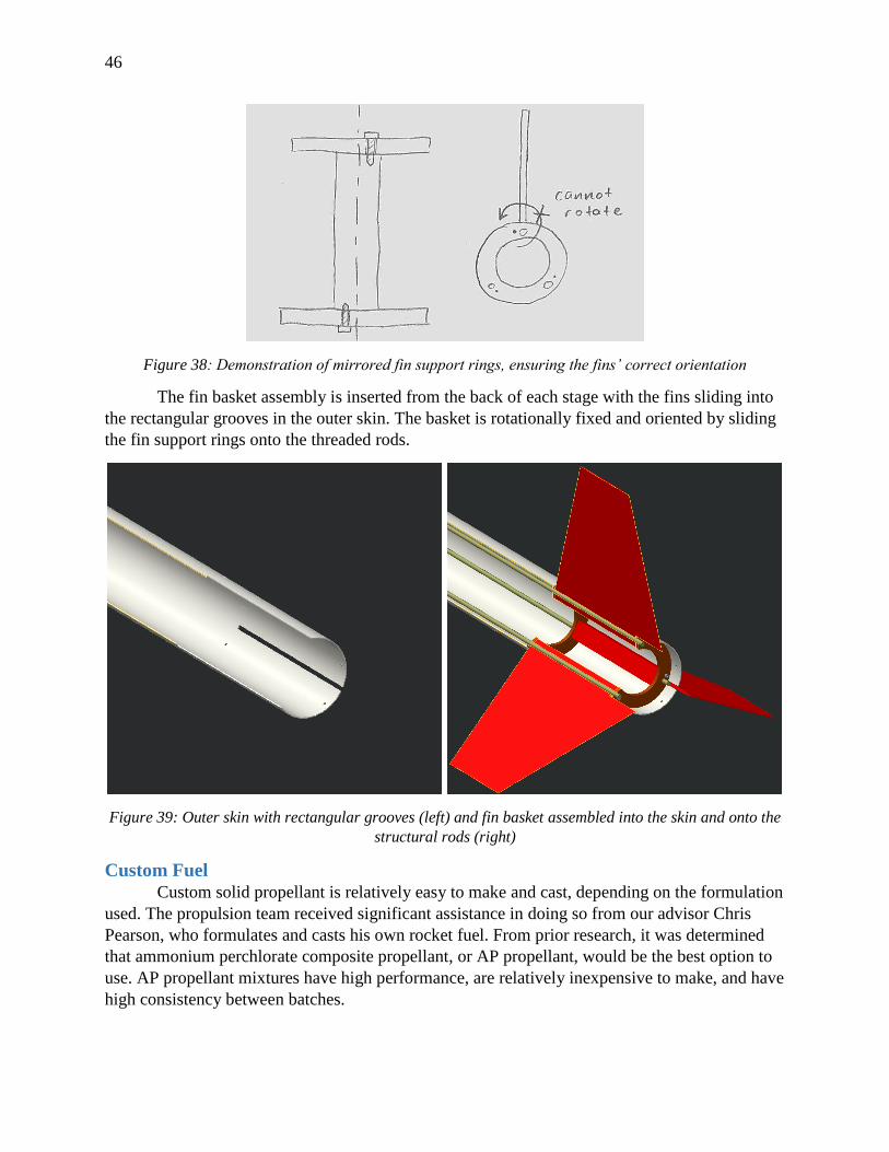
Figure 38: Demonstration of mirrored fin support rings, ensuring the fins’ correct orientation
The fin basket assembly is inserted from the back of each stage with the fins sliding into
the rectangular grooves in the outer skin. The basket is rotationally fixed and oriented by sliding
the fin support rings onto the threaded rods.
Figure 39: Outer skin with rectangular grooves (left) and fin basket assembled into the skin and onto the
structural rods (right)
Custom Fuel
Custom solid propellant is relatively easy to make and cast, depending on the formulation
used. The propulsion team received significant assistance in doing so from our advisor Chris
Pearson, who formulates and casts his own rocket fuel. From prior research, it was determined
that ammonium perchlorate composite propellant, or AP propellant, would be the best option to
use. AP propellant mixtures have high performance, are relatively inexpensive to make, and have
high consistency between batches.
47
An AP fuel has several main components. The ammonium perchlorate itself acts as the
oxididzer, aluminum powder is the fuel, and hydroxyl-terminated polybutadiene (HTPB) serves
as a binder to hold the fuel together. In addition, other compounds can be added to act as burn
rate accelerators or inhibitors. The dry and wet components of this mixture can be blended
together in the proper order using basic equipment – household blenders, containers, and stirrers
can be used. However, the performance of the completed fuel is highly dependent on the specific
proportion of the components. Half-percentage differences in the quantity of aluminum, for
example, may completely throw off the burn characteristics. For this reason, accurate scales are
highly recommended to measure out the ingredients.
The completed fuel mixture is very safe, requiring immense energy to ignite (usually
thermite mixtures are used to actually ignite the fuel). Most of the individual components of the
fuel are also non-toxic and safe, with the important exception of the pure aluminum powder,
which can ignite spontaneously in air.
Once the ingredients are mixed, the fuel is cast into liner tubes which are made to the
exact ID of the phenolic liner tubes inside the motor case. This ensures a very snug fit between
the fuel grains and the phenolic liner. Any gap that exists between the two results in inefficient
combustion.
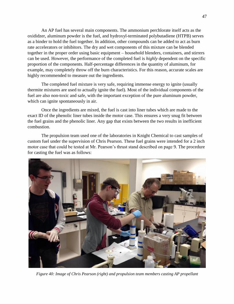
The propulsion team used one of the laboratories in Knight Chemical to cast samples of
custom fuel under the supervision of Chris Pearson. These fuel grains were intended for a 2 inch
motor case that could be tested at Mr. Pearson’s thrust stand described on page 9. The procedure
for casting the fuel was as follows:
Figure 40: Image of Chris Pearson (right) and propulsion team members casting AP propellant
48
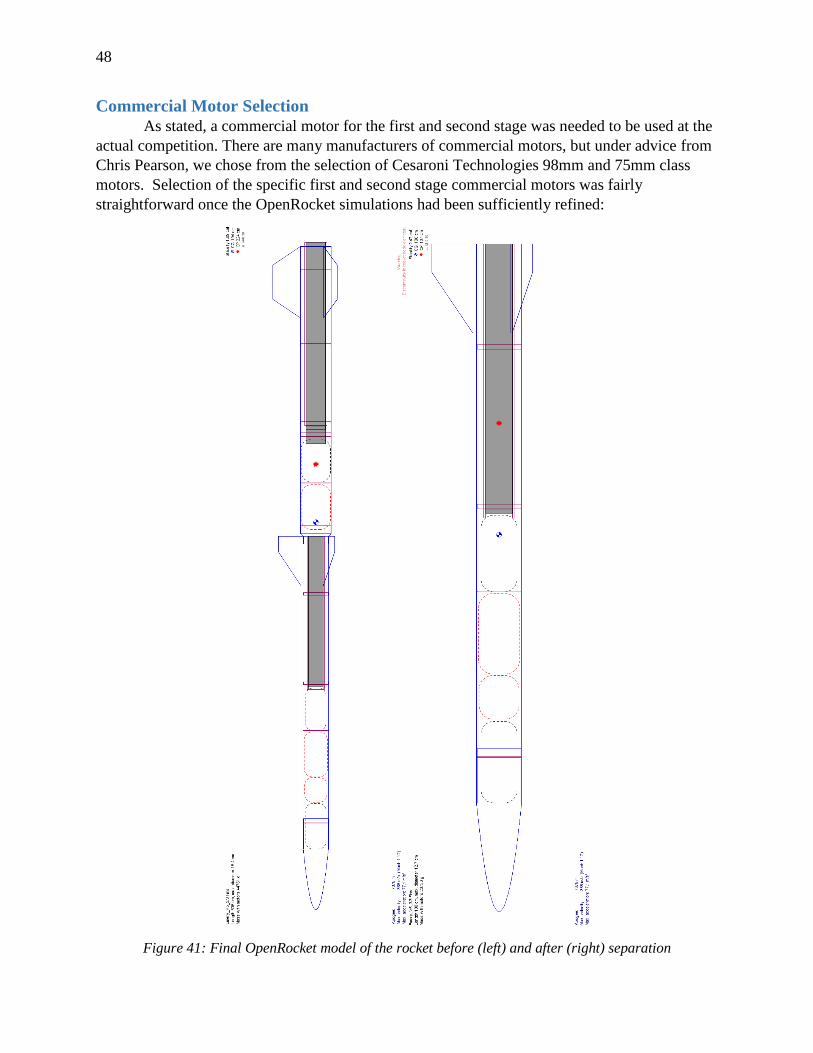
Commercial Motor Selection
As stated, a commercial motor for the first and second stage was needed to be used at the
actual competition. There are many manufacturers of commercial motors, but under advice from
Chris Pearson, we chose from the selection of Cesaroni Technologies 98mm and 75mm class
motors. Selection of the specific first and second stage commercial motors was fairly
straightforward once the OpenRocket simulations had been sufficiently refined:
Figure 41: Final OpenRocket model of the rocket before (left) and after (right) separation
49
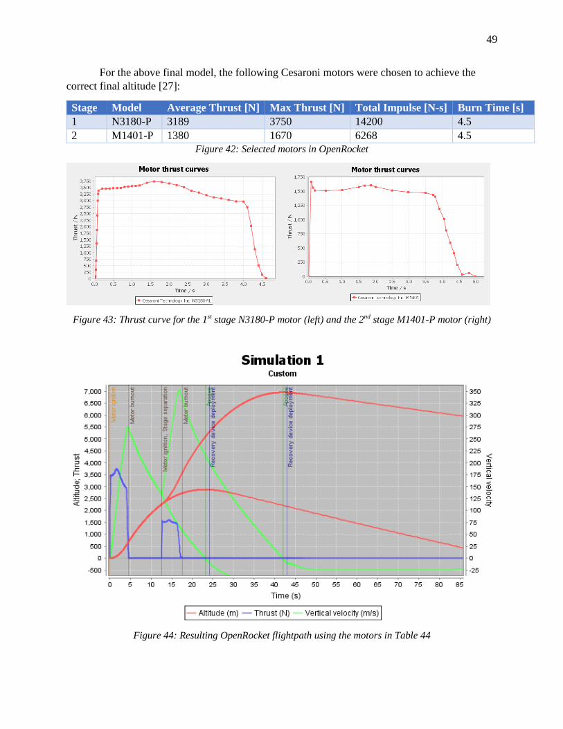
For the above final model, the following Cesaroni motors were chosen to achieve the
correct final altitude [27]:
Stage Model Average Thrust [N] Max Thrust [N] Total Impulse [N-s] Burn Time [s]
1 N3180-P 3189 3750 14200 4.5
2 M1401-P 1380 1670 6268 4.5
Figure 42: Selected motors in OpenRocket
Figure 43: Thrust curve for the 1st stage N3180-P motor (left) and the 2nd stage M1401-P motor (right)
Figure 44: Resulting OpenRocket flightpath using the motors in Table 44
50
As shown, the resulting flightpath for the simulated rocket reaches around 7,000m (~23,000ft),
which is close to the competition target altitude. We decided to purchase these same motors from
Cesaroni for use at competition so that our rocket would closely match the simulation.
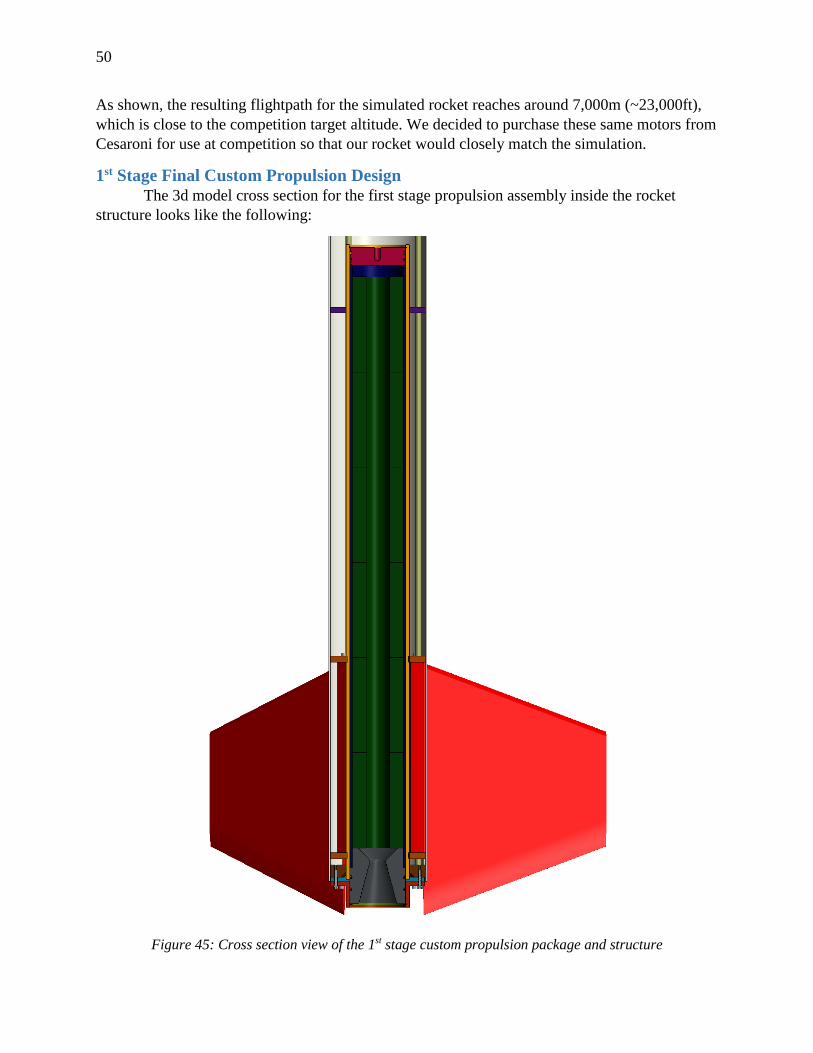
1st Stage Final Custom Propulsion Design
The 3d model cross section for the first stage propulsion assembly inside the rocket
structure looks like the following:
Figure 45: Cross section view of the 1st stage custom propulsion package and structure
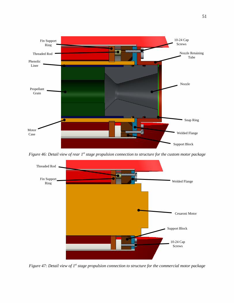
51
Figure 46: Detail view of rear 1st stage propulsion connection to structure for the custom motor package
Figure 47: Detail view of 1st stage propulsion connection to structure for the commercial motor package
Fin Support
Ring
10-24 Cap
Screws
Nozzle Retaining
Tube
Nozzle
Snap Ring
Welded Flange
Support Block
Phenolic
Liner
Propellant
Grain
Motor
Case
Support Block
Welded Flange
Threaded Rod
Threaded Rod
Fin Support
Ring
Cesaroni Motor
10-24 Cap
Screws
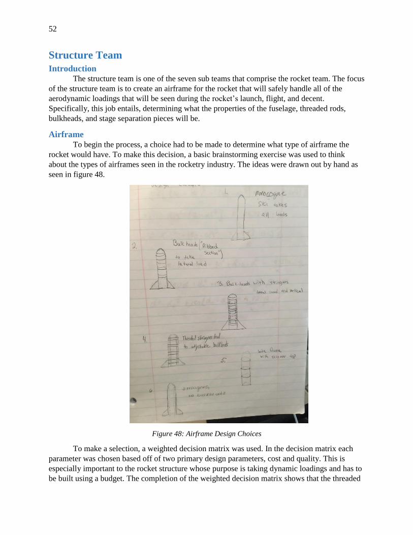
52
Structure Team
Introduction
The structure team is one of the seven sub teams that comprise the rocket team. The focus
of the structure team is to create an airframe for the rocket that will safely handle all of the
aerodynamic loadings that will be seen during the rocket’s launch, flight, and decent.
Specifically, this job entails, determining what the properties of the fuselage, threaded rods,
bulkheads, and stage separation pieces will be.
Airframe
To begin the process, a choice had to be made to determine what type of airframe the
rocket would have. To make this decision, a basic brainstorming exercise was used to think
about the types of airframes seen in the rocketry industry. The ideas were drawn out by hand as
seen in figure 48.
Figure 48: Airframe Design Choices
To make a selection, a weighted decision matrix was used. In the decision matrix each
parameter was chosen based off of two primary design parameters, cost and quality. This is
especially important to the rocket structure whose purpose is taking dynamic loadings and has to
be built using a budget. The completion of the weighted decision matrix shows that the threaded
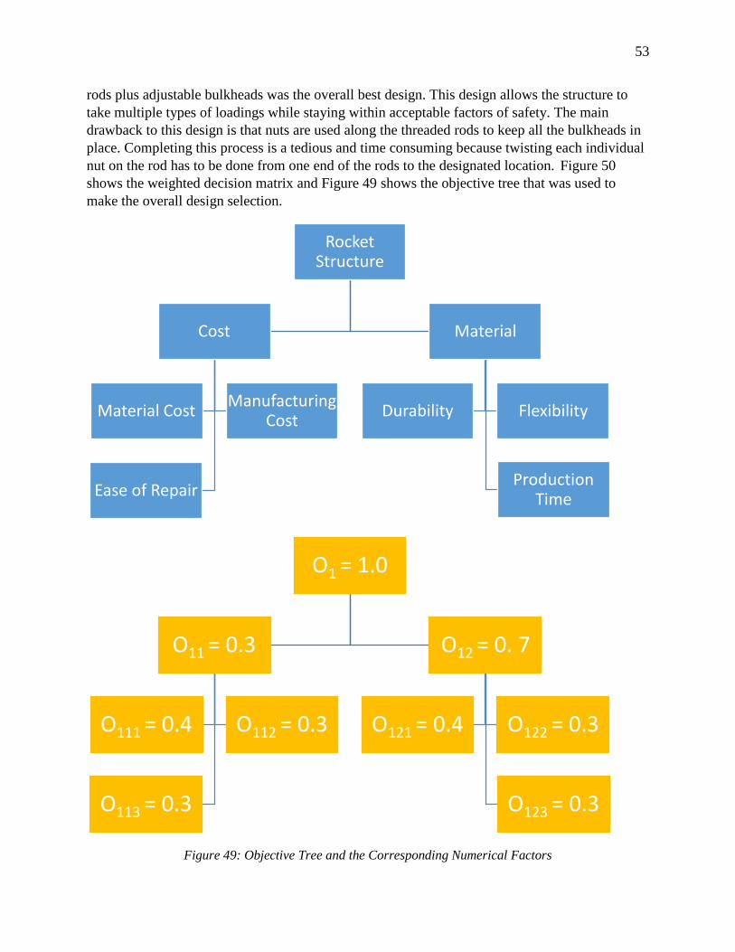
53
rods plus adjustable bulkheads was the overall best design. This design allows the structure to
take multiple types of loadings while staying within acceptable factors of safety. The main
drawback to this design is that nuts are used along the threaded rods to keep all the bulkheads in
place. Completing this process is a tedious and time consuming because twisting each individual
nut on the rod has to be done from one end of the rods to the designated location. Figure 50
shows the weighted decision matrix and Figure 49 shows the objective tree that was used to
make the overall design selection.
Figure 49: Objective Tree and the Corresponding Numerical Factors
Rocket Structure
Cost
Material CostManufacturing
Cost
Ease of Repair
Material
Durability Flexibility
Production Time
O1 = 1.0
O11 = 0.3
O111 = 0.4 O112 = 0.3
O113 = 0.3
O12 = 0. 7
O121 = 0.4 O122 = 0.3
O123 = 0.3
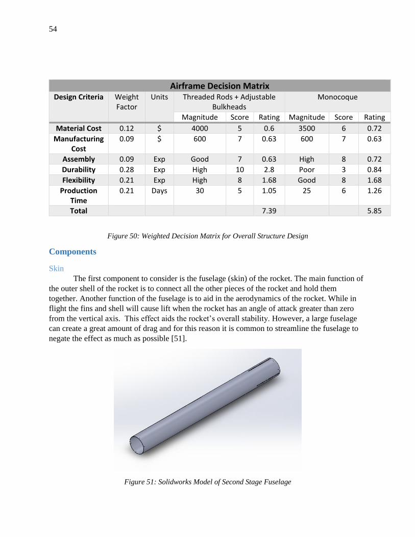
54
Airframe Decision Matrix
Design Criteria Weight Factor
Units Threaded Rods + Adjustable Bulkheads
Monocoque
Magnitude Score Rating Magnitude Score Rating
Material Cost 0.12 $ 4000 5 0.6 3500 6 0.72
Manufacturing Cost
0.09 $ 600 7 0.63 600 7 0.63
Assembly 0.09 Exp Good 7 0.63 High 8 0.72
Durability 0.28 Exp High 10 2.8 Poor 3 0.84
Flexibility 0.21 Exp High 8 1.68 Good 8 1.68
Production Time
0.21 Days 30 5 1.05 25 6 1.26
Total 7.39 5.85
Figure 50: Weighted Decision Matrix for Overall Structure Design
Components
Skin
The first component to consider is the fuselage (skin) of the rocket. The main function of
the outer shell of the rocket is to connect all the other pieces of the rocket and hold them
together. Another function of the fuselage is to aid in the aerodynamics of the rocket. While in
flight the fins and shell will cause lift when the rocket has an angle of attack greater than zero
from the vertical axis. This effect aids the rocket’s overall stability. However, a large fuselage
can create a great amount of drag and for this reason it is common to streamline the fuselage to
negate the effect as much as possible [51].
Figure 51: Solidworks Model of Second Stage Fuselage
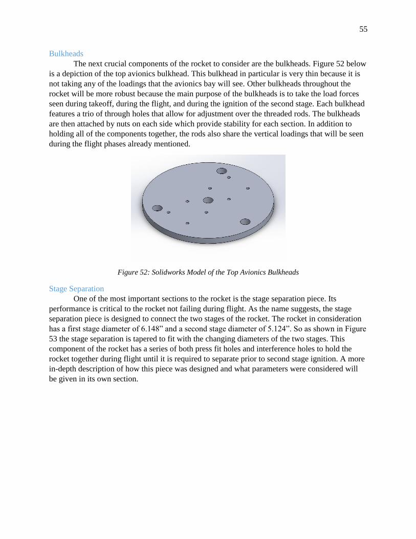
55
Bulkheads
The next crucial components of the rocket to consider are the bulkheads. Figure 52 below
is a depiction of the top avionics bulkhead. This bulkhead in particular is very thin because it is
not taking any of the loadings that the avionics bay will see. Other bulkheads throughout the
rocket will be more robust because the main purpose of the bulkheads is to take the load forces
seen during takeoff, during the flight, and during the ignition of the second stage. Each bulkhead
features a trio of through holes that allow for adjustment over the threaded rods. The bulkheads
are then attached by nuts on each side which provide stability for each section. In addition to
holding all of the components together, the rods also share the vertical loadings that will be seen
during the flight phases already mentioned.
Figure 52: Solidworks Model of the Top Avionics Bulkheads
Stage Separation
One of the most important sections to the rocket is the stage separation piece. Its
performance is critical to the rocket not failing during flight. As the name suggests, the stage
separation piece is designed to connect the two stages of the rocket. The rocket in consideration
has a first stage diameter of 6.148” and a second stage diameter of 5.124”. So as shown in Figure
53 the stage separation is tapered to fit with the changing diameters of the two stages. This
component of the rocket has a series of both press fit holes and interference holes to hold the
rocket together during flight until it is required to separate prior to second stage ignition. A more
in-depth description of how this piece was designed and what parameters were considered will
be given in its own section.
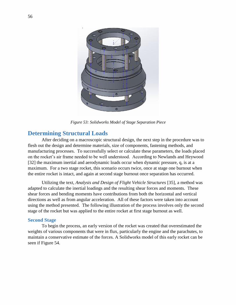
56
Figure 53: Solidworks Model of Stage Separation Piece
Determining Structural Loads After deciding on a macroscopic structural design, the next step in the procedure was to
flesh out the design and determine materials, size of components, fastening methods, and
manufacturing processes. To successfully select or calculate these parameters, the loads placed
on the rocket’s air frame needed to be well understood. According to Newlands and Heywood
[32] the maximum inertial and aerodynamic loads occur when dynamic pressure, q, is at a
maximum. For a two stage rocket, this scenario occurs twice, once at stage one burnout when
the entire rocket is intact, and again at second stage burnout once separation has occurred.
Utilizing the text, Analysis and Design of Flight Vehicle Structures [35], a method was
adapted to calculate the inertial loadings and the resulting shear forces and moments. These
shear forces and bending moments have contributions from both the horizontal and vertical
directions as well as from angular acceleration. All of these factors were taken into account
using the method presented. The following illustration of the process involves only the second
stage of the rocket but was applied to the entire rocket at first stage burnout as well.
Second Stage
To begin the process, an early version of the rocket was created that overestimated the
weights of various components that were in flux, particularly the engine and the parachutes, to
maintain a conservative estimate of the forces. A Solidworks model of this early rocket can be
seen if Figure 54.
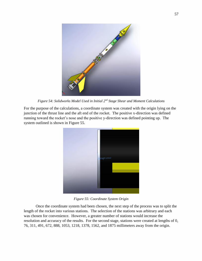
57
Figure 54: Solidworks Model Used in Initial 2nd Stage Shear and Moment Calculations
For the purpose of the calculations, a coordinate system was created with the origin lying on the
junction of the thrust line and the aft end of the rocket. The positive x-direction was defined
running toward the rocket’s nose and the positive y-direction was defined pointing up. The
system outlined is shown in Figure 55.
Figure 55: Coordinate System Origin
Once the coordinate system had been chosen, the next step of the process was to split the
length of the rocket into various stations. The selection of the stations was arbitrary and each
was chosen for convenience. However, a greater number of stations would increase the
resolution and accuracy of the results. For the second stage, stations were created at lengths of 0,
76, 311, 491, 672, 888, 1053, 1218, 1378, 1562, and 1875 millimeters away from the origin.
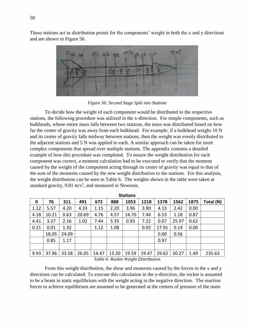
58
These stations act as distribution points for the components’ weight in both the x and y directions
and are shown in Figure 56.
Figure 56: Second Stage Split into Stations
To decide how the weight of each component would be distributed to the respective
stations, the following procedure was utilized in the x-direction. For simple components, such as
bulkheads, whose entire mass falls between two stations, the mass was distributed based on how
far the center of gravity was away from each bulkhead. For example, if a bulkhead weighs 10 N
and its center of gravity falls midway between stations, then the weight was evenly distributed to
the adjacent stations and 5 N was applied to each. A similar approach can be taken for more
complex components that spread over multiple stations. The appendix contains a detailed
example of how this procedure was completed. To ensure the weight distribution for each
component was correct, a moment calculation had to be executed to verify that the moment
caused by the weight of the component acting through its center of gravity was equal to that of
the sum of the moments caused by the new weight distribution to the stations. For this analysis,
the weight distribution can be seen in Table 6. The weights shown in the table were taken at
standard gravity, 9.81 m/s2, and measured in Newtons.
Stations
0 76 311 491 672 888 1053 1218 1378 1562 1875 Total (N)
1.12 5.57 4.20 4.33 1.15 2.20 3.96 3.90 4.13 2.42 0.00
4.18 10.21 0.63 20.69 4.76 4.57 14.70 7.44 6.53 1.18 0.87
4.41 3.27 2.16 1.02 7.44 5.35 0.93 7.22 0.07 25.97 0.62
0.21 0.01 1.32 1.12 1.08 0.92 17.91 0.14 0.00
18.05 24.09 0.00 0.56
0.85 1.17 0.97
9.93 37.96 33.58 26.05 14.47 13.20 19.59 19.47 29.62 30.27 1.49 235.63 Table 6: Rocket Weight Distribution
From this weight distribution, the shear and moments caused by the forces in the x and y
directions can be calculated. To execute this calculation in the y-direction, the rocket is assumed
to be a beam in static equilibrium with the weight acting in the negative direction. The reaction
forces to achieve equilibrium are assumed to be generated at the centers of pressure of the main
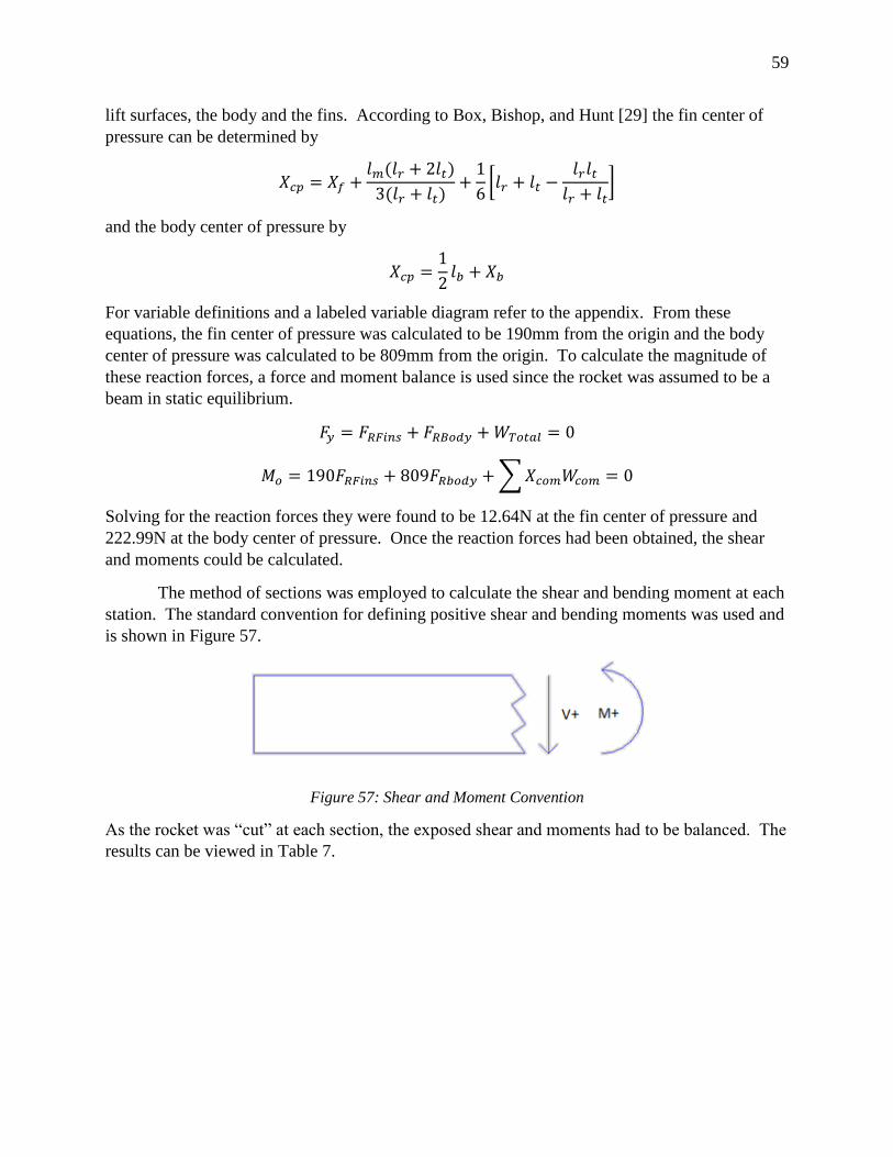
59
lift surfaces, the body and the fins. According to Box, Bishop, and Hunt [29] the fin center of
pressure can be determined by
𝑋𝑐𝑝 = 𝑋𝑓 +𝑙𝑚(𝑙𝑟 + 2𝑙𝑡)
3(𝑙𝑟 + 𝑙𝑡)+
1
6[𝑙𝑟 + 𝑙𝑡 −
𝑙𝑟𝑙𝑡
𝑙𝑟 + 𝑙𝑡]
and the body center of pressure by
𝑋𝑐𝑝 =1
2𝑙𝑏 + 𝑋𝑏
For variable definitions and a labeled variable diagram refer to the appendix. From these
equations, the fin center of pressure was calculated to be 190mm from the origin and the body
center of pressure was calculated to be 809mm from the origin. To calculate the magnitude of
these reaction forces, a force and moment balance is used since the rocket was assumed to be a
beam in static equilibrium.
𝐹𝑦 = 𝐹𝑅𝐹𝑖𝑛𝑠 + 𝐹𝑅𝐵𝑜𝑑𝑦 + 𝑊𝑇𝑜𝑡𝑎𝑙 = 0
𝑀𝑜 = 190𝐹𝑅𝐹𝑖𝑛𝑠 + 809𝐹𝑅𝑏𝑜𝑑𝑦 + ∑ 𝑋𝑐𝑜𝑚𝑊𝑐𝑜𝑚 = 0
Solving for the reaction forces they were found to be 12.64N at the fin center of pressure and
222.99N at the body center of pressure. Once the reaction forces had been obtained, the shear
and moments could be calculated.
The method of sections was employed to calculate the shear and bending moment at each
station. The standard convention for defining positive shear and bending moments was used and
is shown in Figure 57.
Figure 57: Shear and Moment Convention
As the rocket was “cut” at each section, the exposed shear and moments had to be balanced. The
results can be viewed in Table 7.
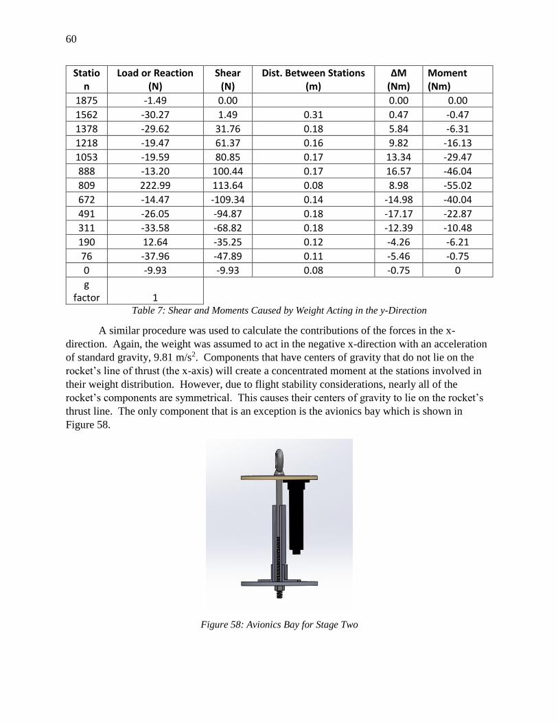
60
Station
Load or Reaction (N)
Shear (N)
Dist. Between Stations (m)
ΔM (Nm)
Moment (Nm)
1875 -1.49 0.00 0.00 0.00
1562 -30.27 1.49 0.31 0.47 -0.47
1378 -29.62 31.76 0.18 5.84 -6.31
1218 -19.47 61.37 0.16 9.82 -16.13
1053 -19.59 80.85 0.17 13.34 -29.47
888 -13.20 100.44 0.17 16.57 -46.04
809 222.99 113.64 0.08 8.98 -55.02
672 -14.47 -109.34 0.14 -14.98 -40.04
491 -26.05 -94.87 0.18 -17.17 -22.87
311 -33.58 -68.82 0.18 -12.39 -10.48
190 12.64 -35.25 0.12 -4.26 -6.21
76 -37.96 -47.89 0.11 -5.46 -0.75
0 -9.93 -9.93 0.08 -0.75 0
g factor 1
Table 7: Shear and Moments Caused by Weight Acting in the y-Direction
A similar procedure was used to calculate the contributions of the forces in the x-
direction. Again, the weight was assumed to act in the negative x-direction with an acceleration
of standard gravity, 9.81 m/s2. Components that have centers of gravity that do not lie on the
rocket’s line of thrust (the x-axis) will create a concentrated moment at the stations involved in
their weight distribution. However, due to flight stability considerations, nearly all of the
rocket’s components are symmetrical. This causes their centers of gravity to lie on the rocket’s
thrust line. The only component that is an exception is the avionics bay which is shown in
Figure 58.
Figure 58: Avionics Bay for Stage Two
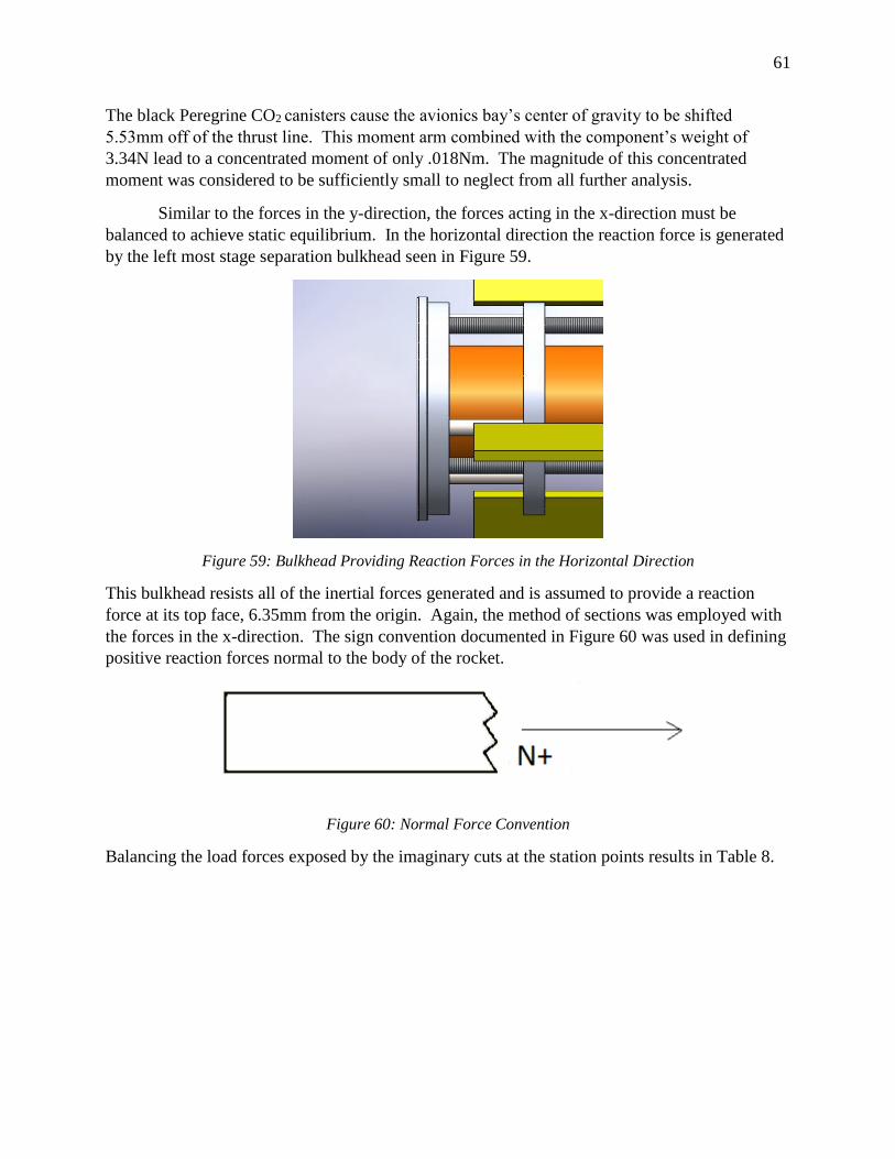
61
The black Peregrine CO2 canisters cause the avionics bay’s center of gravity to be shifted
5.53mm off of the thrust line. This moment arm combined with the component’s weight of
3.34N lead to a concentrated moment of only .018Nm. The magnitude of this concentrated
moment was considered to be sufficiently small to neglect from all further analysis.
Similar to the forces in the y-direction, the forces acting in the x-direction must be
balanced to achieve static equilibrium. In the horizontal direction the reaction force is generated
by the left most stage separation bulkhead seen in Figure 59.
Figure 59: Bulkhead Providing Reaction Forces in the Horizontal Direction
This bulkhead resists all of the inertial forces generated and is assumed to provide a reaction
force at its top face, 6.35mm from the origin. Again, the method of sections was employed with
the forces in the x-direction. The sign convention documented in Figure 60 was used in defining
positive reaction forces normal to the body of the rocket.
Figure 60: Normal Force Convention
Balancing the load forces exposed by the imaginary cuts at the station points results in Table 8.
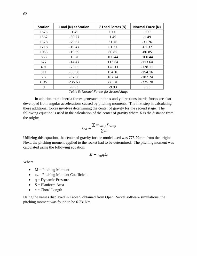
62
Station Load (N) at Station Σ Load Forces (N) Normal Force (N)
1875 -1.49 0.00 0.00
1562 -30.27 1.49 -1.49
1378 -29.62 31.76 -31.76
1218 -19.47 61.37 -61.37
1053 -19.59 80.85 -80.85
888 -13.20 100.44 -100.44
672 -14.47 113.64 -113.64
491 -26.05 128.11 -128.11
311 -33.58 154.16 -154.16
76 -37.96 187.74 -187.74
6.35 235.63 225.70 -225.70
0 -9.93 -9.93 9.93 Table 8: Normal Forces for Second Stage
In addition to the inertia forces generated in the x and y directions inertia forces are also
developed from angular accelerations caused by pitching moments. The first step in calculating
these additional forces involves determining the center of gravity for the second stage. The
following equation is used in the calculation of the center of gravity where X is the distance from
the origin:
𝑋𝐶𝐺 =∑ 𝑚𝑐𝑜𝑚𝑝𝑋𝑐𝑜𝑚𝑝
∑ 𝑚
Utilizing this equation, the center of gravity for the model used was 775.79mm from the origin.
Next, the pitching moment applied to the rocket had to be determined. The pitching moment was
calculated using the following equation:
𝑀 = 𝑐𝑚𝑞𝑆𝑐
Where:
M = Pitching Moment
cm = Pitching Moment Coefficient
q = Dynamic Pressure
S = Planform Area
c = Chord Length
Using the values displayed in Table 9 obtained from Open Rocket software simulations, the
pitching moment was found to be 6.731Nm.
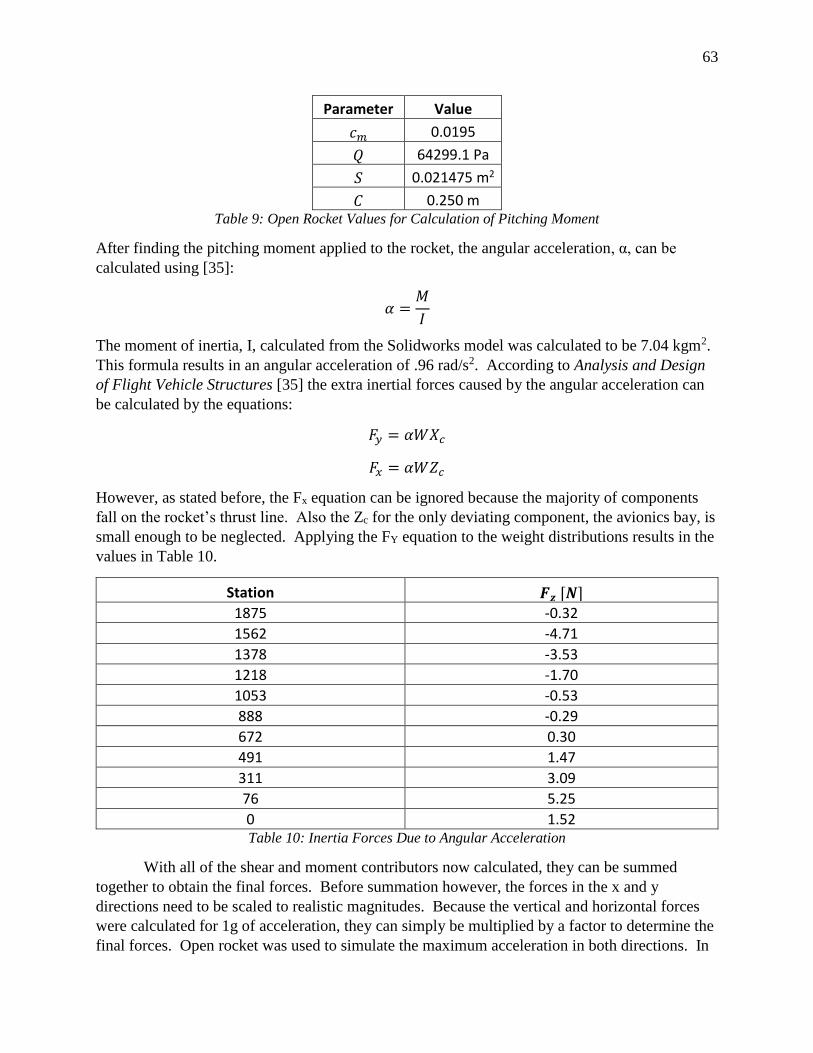
63
Parameter Value
𝑐𝑚 0.0195
𝑄 64299.1 Pa
𝑆 0.021475 m2
𝐶 0.250 m Table 9: Open Rocket Values for Calculation of Pitching Moment
After finding the pitching moment applied to the rocket, the angular acceleration, α, can be
calculated using [35]:
𝛼 =𝑀
𝐼
The moment of inertia, I, calculated from the Solidworks model was calculated to be 7.04 kgm2.
This formula results in an angular acceleration of .96 rad/s2. According to Analysis and Design
of Flight Vehicle Structures [35] the extra inertial forces caused by the angular acceleration can
be calculated by the equations:
𝐹𝑦 = 𝛼𝑊𝑋𝑐
𝐹𝑥 = 𝛼𝑊𝑍𝑐
However, as stated before, the Fx equation can be ignored because the majority of components
fall on the rocket’s thrust line. Also the Zc for the only deviating component, the avionics bay, is
small enough to be neglected. Applying the FY equation to the weight distributions results in the
values in Table 10.
Station 𝑭𝒛 [𝑵] 1875 -0.32
1562 -4.71
1378 -3.53
1218 -1.70
1053 -0.53
888 -0.29
672 0.30
491 1.47
311 3.09
76 5.25
0 1.52 Table 10: Inertia Forces Due to Angular Acceleration
With all of the shear and moment contributors now calculated, they can be summed
together to obtain the final forces. Before summation however, the forces in the x and y
directions need to be scaled to realistic magnitudes. Because the vertical and horizontal forces
were calculated for 1g of acceleration, they can simply be multiplied by a factor to determine the
final forces. Open rocket was used to simulate the maximum acceleration in both directions. In
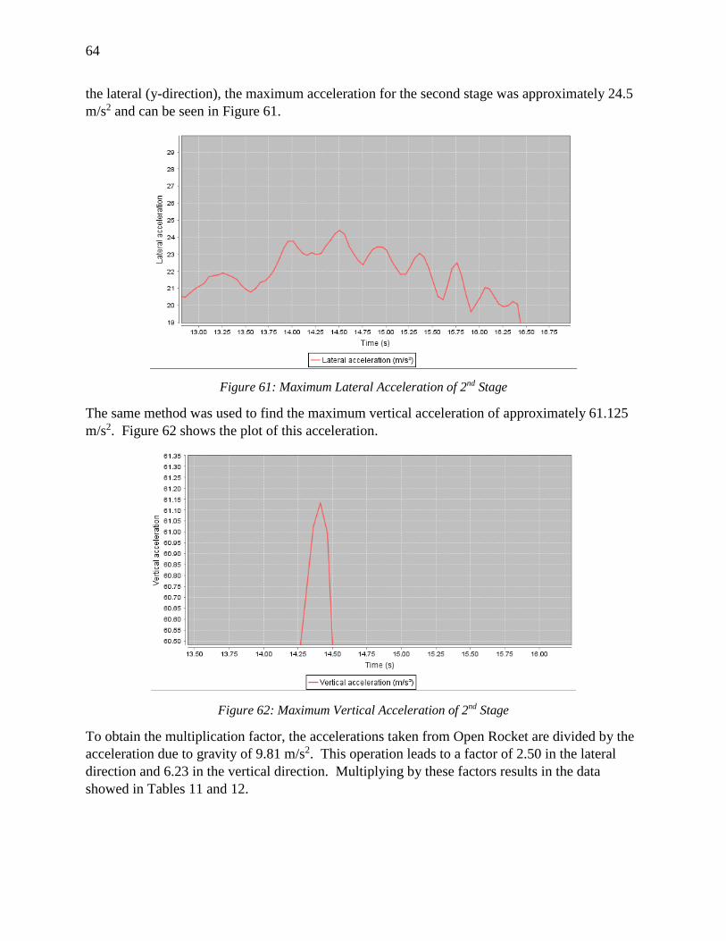
64
the lateral (y-direction), the maximum acceleration for the second stage was approximately 24.5
m/s2 and can be seen in Figure 61.
Figure 61: Maximum Lateral Acceleration of 2nd Stage
The same method was used to find the maximum vertical acceleration of approximately 61.125
m/s2. Figure 62 shows the plot of this acceleration.
Figure 62: Maximum Vertical Acceleration of 2nd Stage
To obtain the multiplication factor, the accelerations taken from Open Rocket are divided by the
acceleration due to gravity of 9.81 m/s2. This operation leads to a factor of 2.50 in the lateral
direction and 6.23 in the vertical direction. Multiplying by these factors results in the data
showed in Tables 11 and 12.
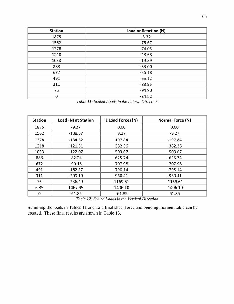
65
Station Load or Reaction (N)
1875 -3.72
1562 -75.67
1378 -74.05
1218 -48.68
1053 -19.59
888 -33.00
672 -36.18
491 -65.12
311 -83.95
76 -94.90
0 -24.82 Table 11: Scaled Loads in the Lateral Direction
Station Load (N) at Station Σ Load Forces (N) Normal Force (N)
1875 -9.27 0.00 0.00
1562 -188.57 9.27 -9.27
1378 -184.52 197.84 -197.84
1218 -121.31 382.36 -382.36
1053 -122.07 503.67 -503.67
888 -82.24 625.74 -625.74
672 -90.16 707.98 -707.98
491 -162.27 798.14 -798.14
311 -209.19 960.41 -960.41
76 -236.49 1169.61 -1169.61
6.35 1467.95 1406.10 -1406.10
0 -61.85 -61.85 61.85 Table 12: Scaled Loads in the Vertical Direction
Summing the loads in Tables 11 and 12 a final shear force and bending moment table can be
created. These final results are shown in Table 13.
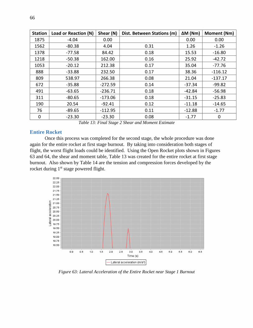
66
Station Load or Reaction (N) Shear (N) Dist. Between Stations (m) ΔM (Nm) Moment (Nm)
1875 -4.04 0.00 0.00 0.00
1562 -80.38 4.04 0.31 1.26 -1.26
1378 -77.58 84.42 0.18 15.53 -16.80
1218 -50.38 162.00 0.16 25.92 -42.72
1053 -20.12 212.38 0.17 35.04 -77.76
888 -33.88 232.50 0.17 38.36 -116.12
809 538.97 266.38 0.08 21.04 -137.17
672 -35.88 -272.59 0.14 -37.34 -99.82
491 -63.65 -236.71 0.18 -42.84 -56.98
311 -80.65 -173.06 0.18 -31.15 -25.83
190 20.54 -92.41 0.12 -11.18 -14.65
76 -89.65 -112.95 0.11 -12.88 -1.77
0 -23.30 -23.30 0.08 -1.77 0 Table 13: Final Stage 2 Shear and Moment Estimate
Entire Rocket
Once this process was completed for the second stage, the whole procedure was done
again for the entire rocket at first stage burnout. By taking into consideration both stages of
flight, the worst flight loads could be identified. Using the Open Rocket plots shown in Figures
63 and 64, the shear and moment table, Table 13 was created for the entire rocket at first stage
burnout. Also shown by Table 14 are the tension and compression forces developed by the
rocket during 1st stage powered flight.
Figure 63: Lateral Acceleration of the Entire Rocket near Stage 1 Burnout
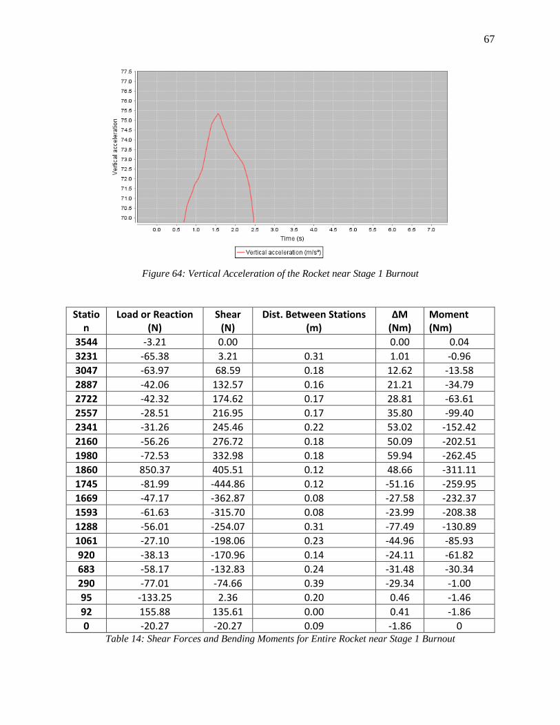
67
Figure 64: Vertical Acceleration of the Rocket near Stage 1 Burnout
Station
Load or Reaction (N)
Shear (N)
Dist. Between Stations (m)
ΔM (Nm)
Moment (Nm)
3544 -3.21 0.00 0.00 0.04
3231 -65.38 3.21 0.31 1.01 -0.96
3047 -63.97 68.59 0.18 12.62 -13.58
2887 -42.06 132.57 0.16 21.21 -34.79
2722 -42.32 174.62 0.17 28.81 -63.61
2557 -28.51 216.95 0.17 35.80 -99.40
2341 -31.26 245.46 0.22 53.02 -152.42
2160 -56.26 276.72 0.18 50.09 -202.51
1980 -72.53 332.98 0.18 59.94 -262.45
1860 850.37 405.51 0.12 48.66 -311.11
1745 -81.99 -444.86 0.12 -51.16 -259.95
1669 -47.17 -362.87 0.08 -27.58 -232.37
1593 -61.63 -315.70 0.08 -23.99 -208.38
1288 -56.01 -254.07 0.31 -77.49 -130.89
1061 -27.10 -198.06 0.23 -44.96 -85.93
920 -38.13 -170.96 0.14 -24.11 -61.82
683 -58.17 -132.83 0.24 -31.48 -30.34
290 -77.01 -74.66 0.39 -29.34 -1.00
95 -133.25 2.36 0.20 0.46 -1.46
92 155.88 135.61 0.00 0.41 -1.86
0 -20.27 -20.27 0.09 -1.86 0 Table 14: Shear Forces and Bending Moments for Entire Rocket near Stage 1 Burnout
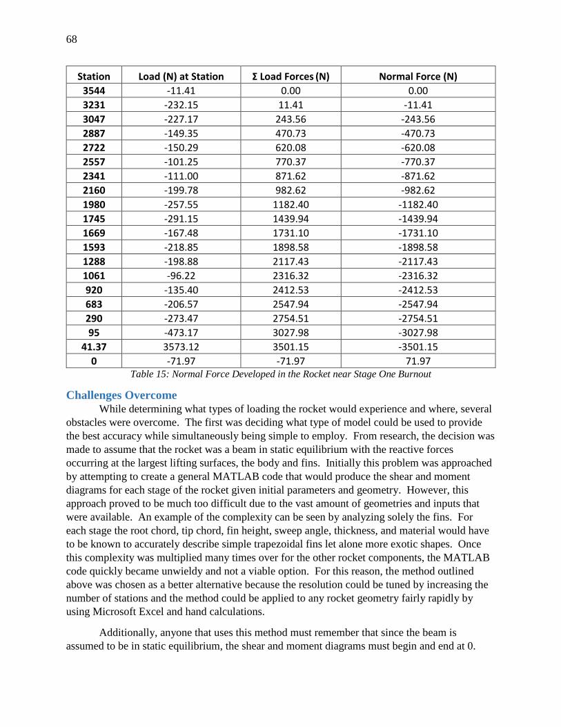
68
Station Load (N) at Station Σ Load Forces (N) Normal Force (N)
3544 -11.41 0.00 0.00
3231 -232.15 11.41 -11.41
3047 -227.17 243.56 -243.56
2887 -149.35 470.73 -470.73
2722 -150.29 620.08 -620.08
2557 -101.25 770.37 -770.37
2341 -111.00 871.62 -871.62
2160 -199.78 982.62 -982.62
1980 -257.55 1182.40 -1182.40
1745 -291.15 1439.94 -1439.94
1669 -167.48 1731.10 -1731.10
1593 -218.85 1898.58 -1898.58
1288 -198.88 2117.43 -2117.43
1061 -96.22 2316.32 -2316.32
920 -135.40 2412.53 -2412.53
683 -206.57 2547.94 -2547.94
290 -273.47 2754.51 -2754.51
95 -473.17 3027.98 -3027.98
41.37 3573.12 3501.15 -3501.15
0 -71.97 -71.97 71.97 Table 15: Normal Force Developed in the Rocket near Stage One Burnout
Challenges Overcome
While determining what types of loading the rocket would experience and where, several
obstacles were overcome. The first was deciding what type of model could be used to provide
the best accuracy while simultaneously being simple to employ. From research, the decision was
made to assume that the rocket was a beam in static equilibrium with the reactive forces
occurring at the largest lifting surfaces, the body and fins. Initially this problem was approached
by attempting to create a general MATLAB code that would produce the shear and moment
diagrams for each stage of the rocket given initial parameters and geometry. However, this
approach proved to be much too difficult due to the vast amount of geometries and inputs that
were available. An example of the complexity can be seen by analyzing solely the fins. For
each stage the root chord, tip chord, fin height, sweep angle, thickness, and material would have
to be known to accurately describe simple trapezoidal fins let alone more exotic shapes. Once
this complexity was multiplied many times over for the other rocket components, the MATLAB
code quickly became unwieldy and not a viable option. For this reason, the method outlined
above was chosen as a better alternative because the resolution could be tuned by increasing the
number of stations and the method could be applied to any rocket geometry fairly rapidly by
using Microsoft Excel and hand calculations.
Additionally, anyone that uses this method must remember that since the beam is
assumed to be in static equilibrium, the shear and moment diagrams must begin and end at 0.
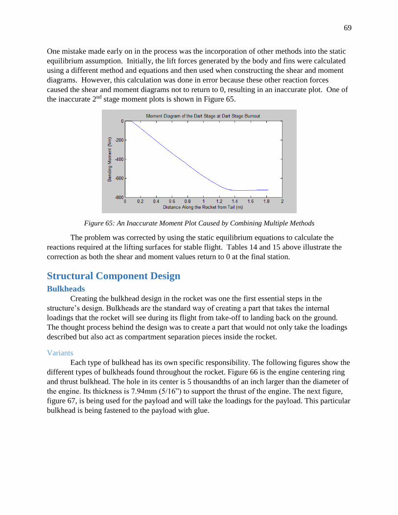
69
One mistake made early on in the process was the incorporation of other methods into the static
equilibrium assumption. Initially, the lift forces generated by the body and fins were calculated
using a different method and equations and then used when constructing the shear and moment
diagrams. However, this calculation was done in error because these other reaction forces
caused the shear and moment diagrams not to return to 0, resulting in an inaccurate plot. One of
the inaccurate 2nd stage moment plots is shown in Figure 65.
Figure 65: An Inaccurate Moment Plot Caused by Combining Multiple Methods
The problem was corrected by using the static equilibrium equations to calculate the
reactions required at the lifting surfaces for stable flight. Tables 14 and 15 above illustrate the
correction as both the shear and moment values return to 0 at the final station.
Structural Component Design
Bulkheads Creating the bulkhead design in the rocket was one the first essential steps in the
structure’s design. Bulkheads are the standard way of creating a part that takes the internal
loadings that the rocket will see during its flight from take-off to landing back on the ground.
The thought process behind the design was to create a part that would not only take the loadings
described but also act as compartment separation pieces inside the rocket.
Variants
Each type of bulkhead has its own specific responsibility. The following figures show the
different types of bulkheads found throughout the rocket. Figure 66 is the engine centering ring
and thrust bulkhead. The hole in its center is 5 thousandths of an inch larger than the diameter of
the engine. Its thickness is 7.94mm (5/16”) to support the thrust of the engine. The next figure,
figure 67, is being used for the payload and will take the loadings for the payload. This particular
bulkhead is being fastened to the payload with glue.
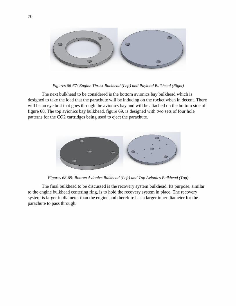
70
Figures 66-67: Engine Thrust Bulkhead (Left) and Payload Bulkhead (Right)
The next bulkhead to be considered is the bottom avionics bay bulkhead which is
designed to take the load that the parachute will be inducing on the rocket when in decent. There
will be an eye bolt that goes through the avionics bay and will be attached on the bottom side of
figure 68. The top avionics bay bulkhead, figure 69, is designed with two sets of four hole
patterns for the CO2 cartridges being used to eject the parachute.
Figures 68-69: Bottom Avionics Bulkhead (Left) and Top Avionics Bulkhead (Top)
The final bulkhead to be discussed is the recovery system bulkhead. Its purpose, similar
to the engine bulkhead centering ring, is to hold the recovery system in place. The recovery
system is larger in diameter than the engine and therefore has a larger inner diameter for the
parachute to pass through.
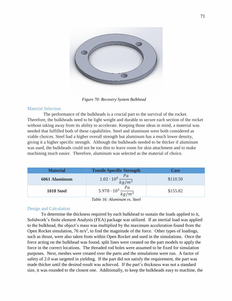
71
Figure 70: Recovery System Bulkhead
Material Selection
The performance of the bulkheads is a crucial part to the survival of the rocket.
Therefore, the bulkheads need to be light weight and durable to secure each section of the rocket
without taking away from its ability to accelerate. Keeping those ideas in mind, a material was
needed that fulfilled both of these capabilities. Steel and aluminum were both considered as
viable choices. Steel had a higher overall strength but aluminum has a much lower density,
giving it a higher specific strength. Although the bulkheads needed to be thicker if aluminum
was used, the bulkheads could not be too thin to leave room for skin attachment and to make
machining much easier. Therefore, aluminum was selected as the material of choice.
Material Tensile Specific Strength Cost
6061 Aluminum 1.02 ∙ 105𝑃𝑎
𝑘𝑔/𝑚3 $110.50
1018 Steel 5.978 ∙ 103𝑃𝑎
𝑘𝑔/𝑚3 $155.82
Table 16: Aluminum vs. Steel
Design and Calculation
To determine the thickness required by each bulkhead to sustain the loads applied to it,
Solidwork’s finite element Analysis (FEA) package was utilized. If an inertial load was applied
to the bulkhead, the object’s mass was multiplied by the maximum acceleration found from the
Open Rocket simulation, 76 m/s2, to find the magnitude of the force. Other types of loadings,
such as thrust, were also taken from within Open Rocket and used in the simulations. Once the
force acting on the bulkhead was found, split lines were created on the part models to apply the
force in the correct locations. The threaded rod holes were assumed to be fixed for simulation
purposes. Next, meshes were created over the parts and the simulations were run. A factor of
safety of 2.0 was targeted in yielding. If the part did not satisfy the requirement, the part was
made thicker until the desired result was achieved. If the part’s thickness was not a standard
size, it was rounded to the closest one. Additionally, to keep the bulkheads easy to machine, the
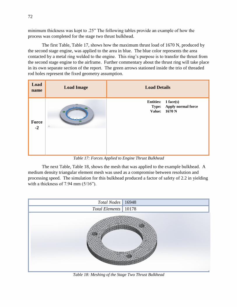
72
minimum thickness was kept to .25” The following tables provide an example of how the
process was completed for the stage two thrust bulkhead.
The first Table, Table 17, shows how the maximum thrust load of 1670 N, produced by
the second stage engine, was applied to the area in blue. The blue color represents the area
contacted by a metal ring welded to the engine. This ring’s purpose is to transfer the thrust from
the second stage engine to the airframe. Further commentary about the thrust ring will take place
in its own separate section of the report. The green arrows stationed inside the trio of threaded
rod holes represent the fixed geometry assumption.
Load
name Load Image Load Details
Force
-2
Entities: 1 face(s)
Type: Apply normal force
Value: 1670 N
Table 17: Forces Applied to Engine Thrust Bulkhead
The next Table, Table 18, shows the mesh that was applied to the example bulkhead. A
medium density triangular element mesh was used as a compromise between resolution and
processing speed. The simulation for this bulkhead produced a factor of safety of 2.2 in yielding
with a thickness of 7.94 mm (5/16”).
Total Nodes 16948
Total Elements 10178
Table 18: Meshing of the Stage Two Thrust Bulkhead
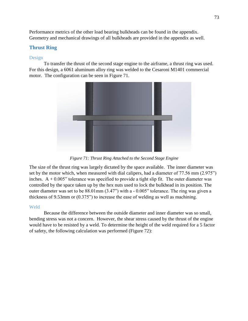
73
Performance metrics of the other load bearing bulkheads can be found in the appendix.
Geometry and mechanical drawings of all bulkheads are provided in the appendix as well.
Thrust Ring
Design
To transfer the thrust of the second stage engine to the airframe, a thrust ring was used.
For this design, a 6061 aluminum alloy ring was welded to the Cesaroni M1401 commercial
motor. The configuration can be seen in Figure 71.
Figure 71: Thrust Ring Attached to the Second Stage Engine
The size of the thrust ring was largely dictated by the space available. The inner diameter was
set by the motor which, when measured with dial calipers, had a diameter of 77.56 mm (2.975”)
inches. A + 0.005” tolerance was specified to provide a tight slip fit. The outer diameter was
controlled by the space taken up by the hex nuts used to lock the bulkhead in its position. The
outer diameter was set to be 88.01mm (3.47”) with a - 0.005” tolerance. The ring was given a
thickness of 9.53mm or (0.375”) to increase the ease of welding as well as machining.
Weld
Because the difference between the outside diameter and inner diameter was so small,
bending stress was not a concern. However, the shear stress caused by the thrust of the engine
would have to be resisted by a weld. To determine the height of the weld required for a 5 factor
of safety, the following calculation was performed (Figure 72):
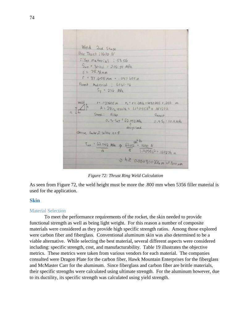
74
Figure 72: Thrust Ring Weld Calculation
As seen from Figure 72, the weld height must be more the .800 mm when 5356 filler material is
used for the application.
Skin
Material Selection
To meet the performance requirements of the rocket, the skin needed to provide
functional strength as well as being light weight. For this reason a number of composite
materials were considered as they provide high specific strength ratios. Among those explored
were carbon fiber and fiberglass. Conventional aluminum skin was also determined to be a
viable alternative. While selecting the best material, several different aspects were considered
including: specific strength, cost, and manufacturability. Table 19 illustrates the objective
metrics. These metrics were taken from various vendors for each material. The companies
consulted were Dragon Plate for the carbon fiber, Hawk Mountain Enterprises for the fiberglass
and McMaster Carr for the aluminum. Since fiberglass and carbon fiber are brittle materials,
their specific strengths were calculated using ultimate strength. For the aluminum however, due
to its ductility, its specific strength was calculated using yield strength.
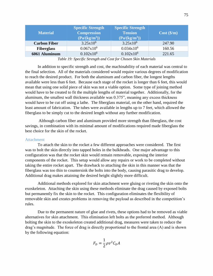
75
Material
Specific Strength
Compression
(Pa/(kg/m3))
Specific Strength
Tension
(Pa/(kg/m3))
Cost ($/m)
Carbon Fiber 3.25x10⁶ 3.25x10⁶ 247.90
Fiberglass 0.067x10⁶ 0.034x10⁶ 160.56
6061 Aluminum 0.102x10⁶ 0.102x10⁶ 221.65
Table 19: Specific Strength and Cost for Chosen Skin Materials
In addition to specific strength and cost, the machinability of each material was central to
the final selection. All of the materials considered would require various degrees of modification
to reach the desired product. For both the aluminum and carbon fiber, the longest lengths
available were less than 6 feet. Because each stage of the rocket is longer than 6 feet, this would
mean that using one solid piece of skin was not a viable option. Some type of joining method
would have to be created to fit the multiple lengths of material together. Additionally, for the
aluminum, the smallest wall thickness available was 0.375”, meaning any excess thickness
would have to be cut off using a lathe. The fiberglass material, on the other hand, required the
least amount of fabrication. The tubes were available in lengths up to 7 feet, which allowed the
fiberglass to be simply cut to the desired length without any further modification.
Although carbon fiber and aluminum provided more strength than fiberglass, the cost
savings, in combination with its minimal amount of modifications required made fiberglass the
best choice for the skin of the rocket.
Attachment
To attach the skin to the rocket a few different approaches were considered. The first
was to bolt the skin directly into tapped holes in the bulkheads. One major advantage to this
configuration was that the rocket skin would remain removable, exposing the interior
components of the rocket. This setup would allow any repairs or work to be completed without
taking the entire rocket apart. The drawback to attaching the skin in this manner was that the
fiberglass was too thin to countersink the bolts into the body, causing parasitic drag to develop.
Additional drag makes attaining the desired height slightly more difficult.
Additional methods explored for skin attachment were gluing or riveting the skin onto the
exoskeleton. Attaching the skin using these methods eliminate the drag caused by exposed bolts
but permanently fix the skin to the rocket. This configuration eliminates the flexibility of
removable skin and creates problems in removing the payload as described in the competition’s
rules.
Due to the permanent nature of glue and rivets, these options had to be removed as viable
alternatives for skin attachment. This elimination left bolts as the preferred method. Although
bolting the skin to the exoskeleton created additional drag, measures were taken to reduce the
drag’s magnitude. The force of drag is directly proportional to the frontal area (A) and is shown
by the following equation:
𝐹𝐷 =1
2𝜌𝑣2𝐶𝐷𝐴
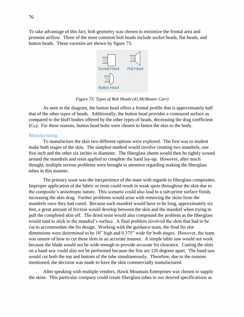
76
To take advantage of this fact, bolt geometry was chosen to minimize the frontal area and
promote airflow. Three of the most common bolt heads include socket heads, flat heads, and
button heads. These varieties are shown by figure 73.
Figure 73: Types of Bolt Heads (41,McMaster Carr)
As seen in the diagram, the button head offers a frontal profile that is approximately half
that of the other types of heads. Additionally, the button head provides a contoured surface as
compared to the bluff bodies offered by the other types of heads, decreasing the drag coefficient
(CD). For these reasons, button head bolts were chosen to fasten the skin to the body.
Manufacturing
To manufacture the skin two different options were explored. The first was to student
make both stages of the skin. The simplest method would involve creating two mandrels, one
five inch and the other six inches in diameter. The fiberglass sheets would then be tightly wound
around the mandrels and resin applied to complete the hand lay-up. However, after much
thought, multiple serious problems were brought to attention regarding making the fiberglass
tubes in this manner.
The primary issue was the inexperience of the team with regards to fiberglass composites.
Improper application of the fabric or resin could result in weak spots throughout the skin due to
the composite’s anisotropic nature. This scenario could also lead to a sub-prime surface finish,
increasing the skin drag. Further problems would arise with removing the skins from the
mandrels once they had cured. Because each mandrel would have to be long, approximately six
feet, a great amount of friction would develop between the skin and the mandrel when trying to
pull the completed skin off. The dried resin would also compound the problem as the fiberglass
would tend to stick to the mandrel’s surface. A final problem involved the slots that had to be
cut to accommodate the fin design. Working with the guidance team, the final fin slot
dimensions were determined to be 10” high and 0.375” wide for both stages. However, the team
was unsure of how to cut these slots in an accurate manner. A simple table saw would not work
because the blade would not be wide enough to provide accurate fin clearance. Cutting the slots
on a band saw could also not be performed because the fins are 120 degrees apart. The band saw
would cut both the top and bottom of the tube simultaneously. Therefore, due to the reasons
mentioned, the decision was made to have the skin commercially manufactured.
After speaking with multiple vendors, Hawk Mountain Enterprises was chosen to supply
the skins. This particular company could create fiberglass tubes to our desired specifications as
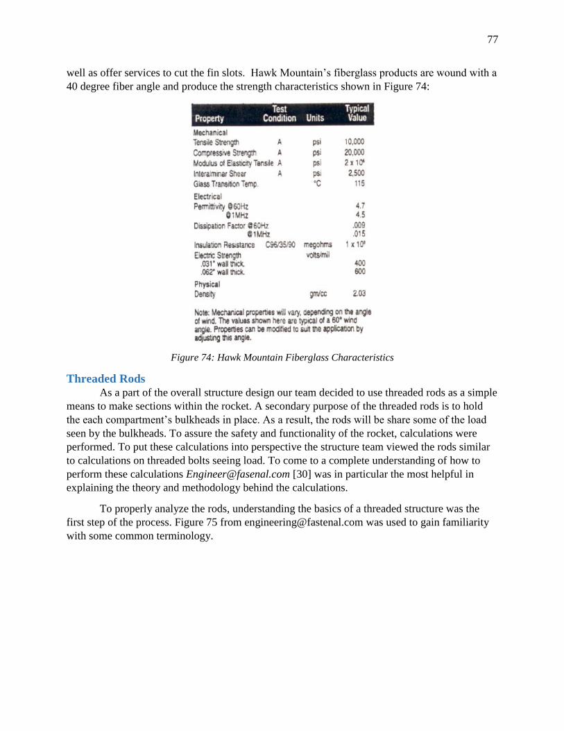
77
well as offer services to cut the fin slots. Hawk Mountain’s fiberglass products are wound with a
40 degree fiber angle and produce the strength characteristics shown in Figure 74:
Figure 74: Hawk Mountain Fiberglass Characteristics
Threaded Rods
As a part of the overall structure design our team decided to use threaded rods as a simple
means to make sections within the rocket. A secondary purpose of the threaded rods is to hold
the each compartment’s bulkheads in place. As a result, the rods will be share some of the load
seen by the bulkheads. To assure the safety and functionality of the rocket, calculations were
performed. To put these calculations into perspective the structure team viewed the rods similar
to calculations on threaded bolts seeing load. To come to a complete understanding of how to
perform these calculations [email protected] [30] was in particular the most helpful in
explaining the theory and methodology behind the calculations.
To properly analyze the rods, understanding the basics of a threaded structure was the
first step of the process. Figure 75 from [email protected] was used to gain familiarity
with some common terminology.
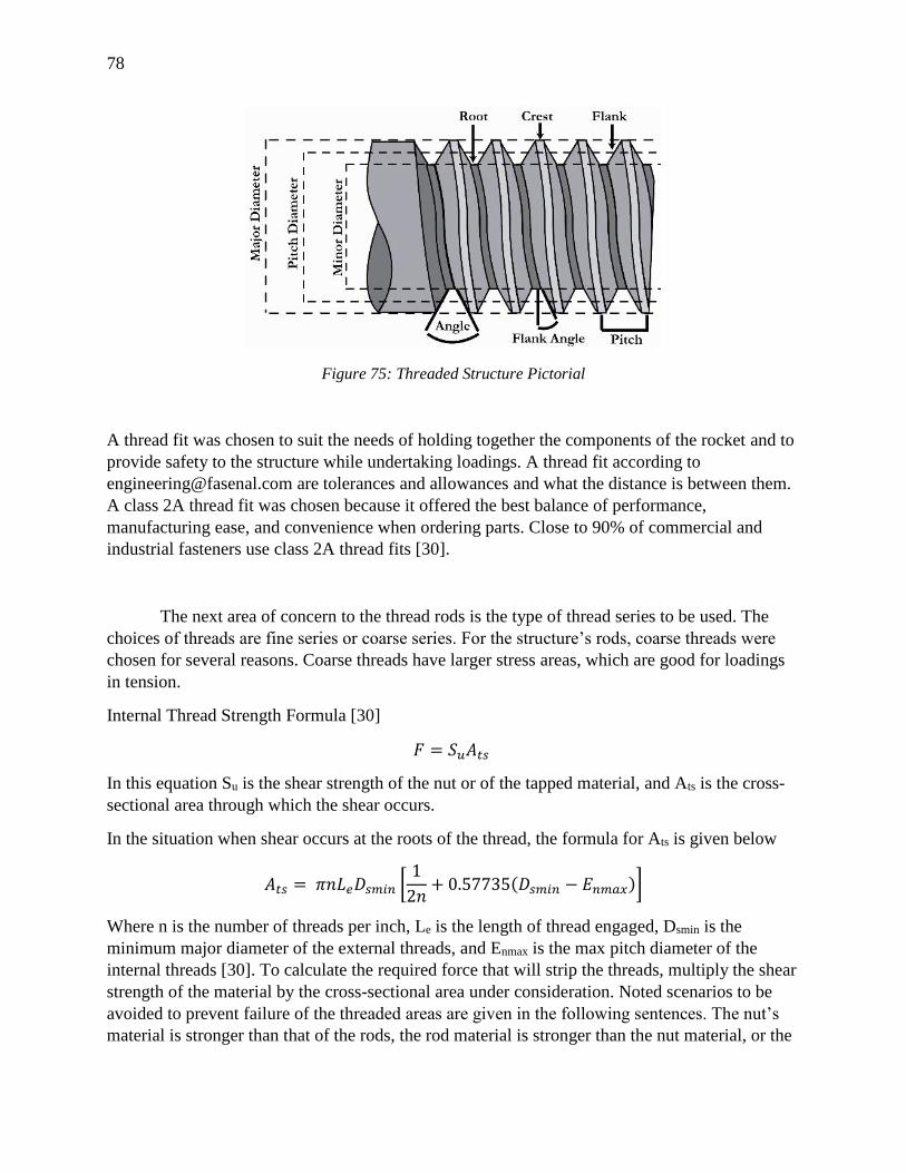
78
Figure 75: Threaded Structure Pictorial
A thread fit was chosen to suit the needs of holding together the components of the rocket and to
provide safety to the structure while undertaking loadings. A thread fit according to
[email protected] are tolerances and allowances and what the distance is between them.
A class 2A thread fit was chosen because it offered the best balance of performance,
manufacturing ease, and convenience when ordering parts. Close to 90% of commercial and
industrial fasteners use class 2A thread fits [30].
The next area of concern to the thread rods is the type of thread series to be used. The
choices of threads are fine series or coarse series. For the structure’s rods, coarse threads were
chosen for several reasons. Coarse threads have larger stress areas, which are good for loadings
in tension.
Internal Thread Strength Formula [30]
𝐹 = 𝑆𝑢𝐴𝑡𝑠
In this equation Su is the shear strength of the nut or of the tapped material, and Ats is the cross-
sectional area through which the shear occurs.
In the situation when shear occurs at the roots of the thread, the formula for Ats is given below
𝐴𝑡𝑠 = 𝜋𝑛𝐿𝑒𝐷𝑠𝑚𝑖𝑛 [1
2𝑛+ 0.57735(𝐷𝑠𝑚𝑖𝑛 − 𝐸𝑛𝑚𝑎𝑥)]
Where n is the number of threads per inch, Le is the length of thread engaged, Dsmin is the
minimum major diameter of the external threads, and Enmax is the max pitch diameter of the
internal threads [30]. To calculate the required force that will strip the threads, multiply the shear
strength of the material by the cross-sectional area under consideration. Noted scenarios to be
avoided to prevent failure of the threaded areas are given in the following sentences. The nut’s
material is stronger than that of the rods, the rod material is stronger than the nut material, or the
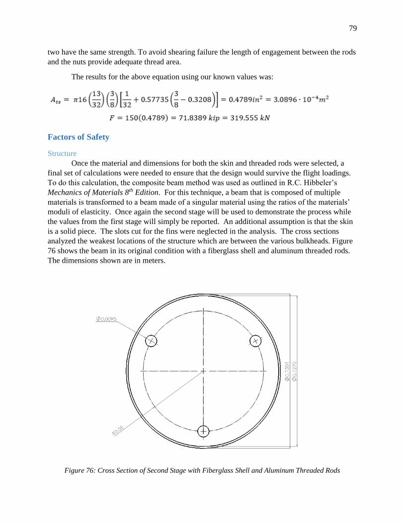
79
two have the same strength. To avoid shearing failure the length of engagement between the rods
and the nuts provide adequate thread area.
The results for the above equation using our known values was:
Factors of Safety
Structure
Once the material and dimensions for both the skin and threaded rods were selected, a
final set of calculations were needed to ensure that the design would survive the flight loadings.
To do this calculation, the composite beam method was used as outlined in R.C. Hibbeler’s
Mechanics of Materials 8th Edition. For this technique, a beam that is composed of multiple
materials is transformed to a beam made of a singular material using the ratios of the materials’
moduli of elasticity. Once again the second stage will be used to demonstrate the process while
the values from the first stage will simply be reported. An additional assumption is that the skin
is a solid piece. The slots cut for the fins were neglected in the analysis. The cross sections
analyzed the weakest locations of the structure which are between the various bulkheads. Figure
76 shows the beam in its original condition with a fiberglass shell and aluminum threaded rods.
The dimensions shown are in meters.
Figure 76: Cross Section of Second Stage with Fiberglass Shell and Aluminum Threaded Rods
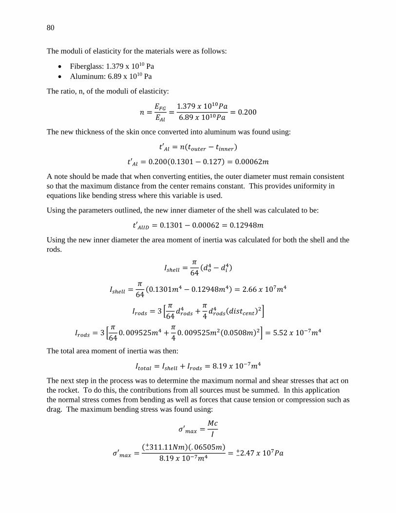
80
The moduli of elasticity for the materials were as follows:
Fiberglass: 1.379 x 10¹⁰ Pa
Aluminum: 6.89 x 10¹⁰ Pa
The ratio, n, of the moduli of elasticity:
𝑛 =𝐸𝐹𝐺
𝐸𝐴𝑙=
1.379 𝑥 1010𝑃𝑎
6.89 𝑥 1010𝑃𝑎= 0.200
The new thickness of the skin once converted into aluminum was found using:
𝑡′𝐴𝑙 = 𝑛(𝑡𝑜𝑢𝑡𝑒𝑟 − 𝑡𝑖𝑛𝑛𝑒𝑟)
𝑡′𝐴𝑙 = 0.200(0.1301 − 0.127) = 0.00062𝑚
A note should be made that when converting entities, the outer diameter must remain consistent
so that the maximum distance from the center remains constant. This provides uniformity in
equations like bending stress where this variable is used.
Using the parameters outlined, the new inner diameter of the shell was calculated to be:
𝑡′𝐴𝑙𝐼𝐷 = 0.1301 − 0.00062 = 0.12948𝑚
Using the new inner diameter the area moment of inertia was calculated for both the shell and the
rods.
𝐼𝑠ℎ𝑒𝑙𝑙 =𝜋
64(𝑑𝑜
4 − 𝑑𝑖4)
𝐼𝑠ℎ𝑒𝑙𝑙 =𝜋
64(0.1301𝑚4 − 0.12948𝑚4) = 2.66 𝑥 107𝑚4
𝐼𝑟𝑜𝑑𝑠 = 3 [𝜋
64𝑑𝑟𝑜𝑑𝑠
4 +𝜋
4𝑑𝑟𝑜𝑑𝑠
4 (𝑑𝑖𝑠𝑡𝑐𝑒𝑛𝑡)2]
𝐼𝑟𝑜𝑑𝑠 = 3 [𝜋
640. 009525𝑚4 +
𝜋
40. 009525𝑚2(0.0508𝑚)2] = 5.52 𝑥 10−7𝑚4
The total area moment of inertia was then:
𝐼𝑡𝑜𝑡𝑎𝑙 = 𝐼𝑠ℎ𝑒𝑙𝑙 + 𝐼𝑟𝑜𝑑𝑠 = 8.19 𝑥 10−7𝑚4
The next step in the process was to determine the maximum normal and shear stresses that act on
the rocket. To do this, the contributions from all sources must be summed. In this application
the normal stress comes from bending as well as forces that cause tension or compression such as
drag. The maximum bending stress was found using:
𝜎′𝑚𝑎𝑥 =𝑀𝑐
𝐼
𝜎′𝑚𝑎𝑥 =( 311.11𝑁𝑚−
+ )(. 06505𝑚)
8.19 𝑥 10−7𝑚4= 2.47−
+ 𝑥 107𝑃𝑎
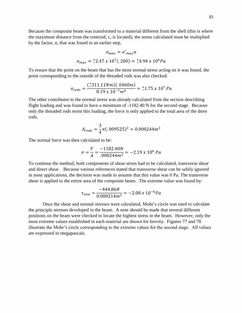
81
Because the composite beam was transformed to a material different from the shell (this is where
the maximum distance from the centroid, c, is located), the stress calculated must be multiplied
by the factor, n, that was found in an earlier step.
𝜎𝑚𝑎𝑥 = 𝜎′𝑚𝑎𝑥𝑛
𝜎𝑚𝑎𝑥 = 2.47 −+ 𝑥 107(. 200) = 4.94−
+ 𝑥 106𝑃𝑎
To ensure that the point on the beam that has the most normal stress acting on it was found, the
point corresponding to the outside of the threaded rods was also checked.
𝜎𝑟𝑜𝑑𝑠 =( 311.11𝑁𝑚−
+ )(. 0460𝑚)
8.19 𝑥 10−7𝑚4= 1.75 𝑥 107 𝑃𝑎−
+
The other contributor to the normal stress was already calculated from the section describing
flight loading and was found to have a minimum of -1182.40 N for the second stage. Because
only the threaded rods resist this loading, the force is only applied to the total area of the three
rods.
𝐴𝑟𝑜𝑑𝑠 =3
4𝜋(. 009525)2 = 0.000244𝑚2
The normal force was then calculated to be:
𝜎 =𝐹
𝐴=
−1182.40𝑁
. 000244𝑚2= −2.19 𝑥 106 𝑃𝑎
To continue the method, both components of shear stress had to be calculated, transverse shear
and direct shear. Because various references stated that transverse shear can be safely ignored
in most applications, the decision was made to assume that this value was 0 Pa. The transverse
shear is applied to the entire area of the composite beam. The extreme value was found by:
𝜏𝑚𝑖𝑛 =−444.86𝑁
0.000214𝑚2= −2.08 𝑥 10−6𝑃𝑎
Once the shear and normal stresses were calculated, Mohr’s circle was used to calculate
the principle stresses developed in the beam. A note should be made that several different
positions on the beam were checked to locate the highest stress in the beam. However, only the
most extreme values established in each material are shown for brevity. Figures 77 and 78
illustrate the Mohr’s circle corresponding to the extreme values for the second stage. All values
are expressed in megapascals.
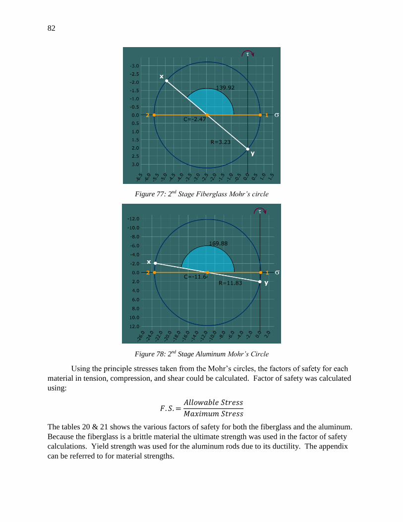
82
Figure 77: 2nd Stage Fiberglass Mohr’s circle
Figure 78: 2nd Stage Aluminum Mohr’s Circle
Using the principle stresses taken from the Mohr’s circles, the factors of safety for each
material in tension, compression, and shear could be calculated. Factor of safety was calculated
using:
𝐹. 𝑆. =𝐴𝑙𝑙𝑜𝑤𝑎𝑏𝑙𝑒 𝑆𝑡𝑟𝑒𝑠𝑠
𝑀𝑎𝑥𝑖𝑚𝑢𝑚 𝑆𝑡𝑟𝑒𝑠𝑠
The tables 20 & 21 shows the various factors of safety for both the fiberglass and the aluminum.
Because the fiberglass is a brittle material the ultimate strength was used in the factor of safety
calculations. Yield strength was used for the aluminum rods due to its ductility. The appendix
can be referred to for material strengths.
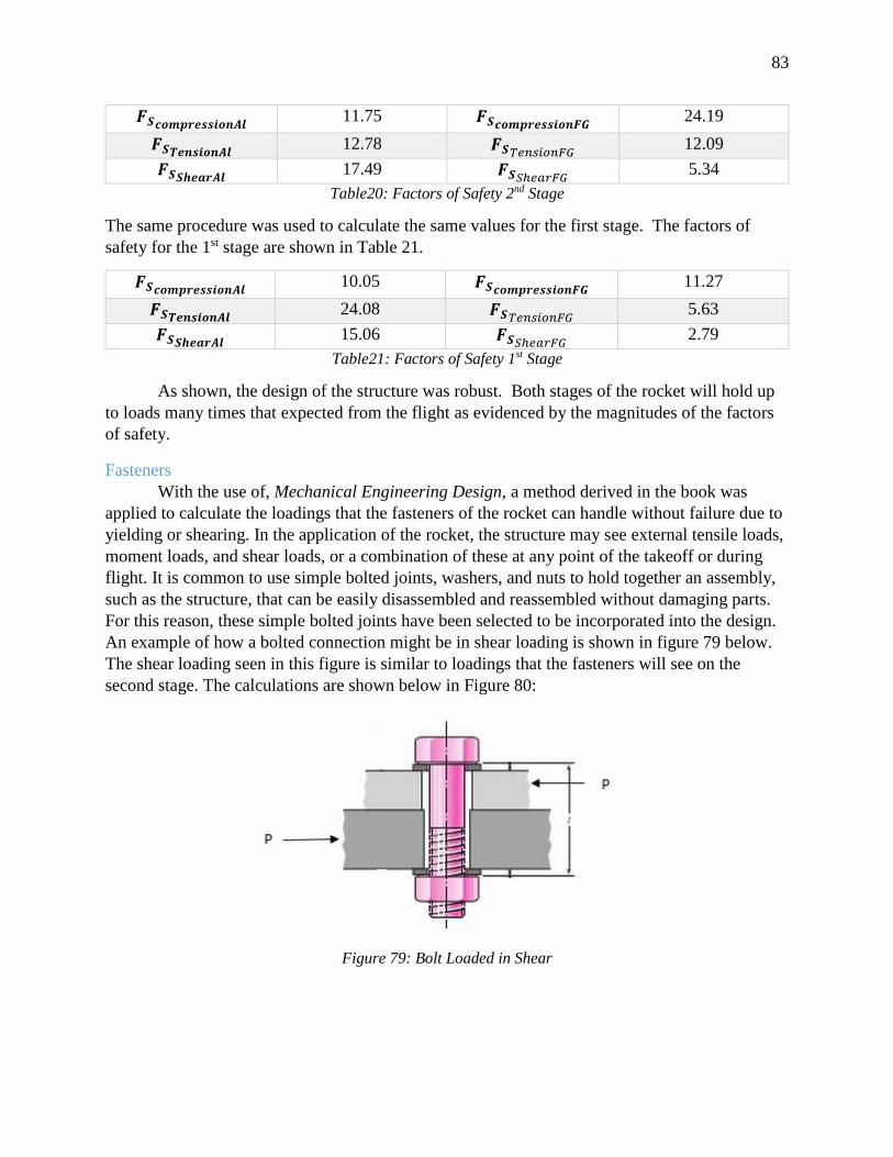
83
𝑭𝑺𝒄𝒐𝒎𝒑𝒓𝒆𝒔𝒔𝒊𝒐𝒏𝑨𝒍 11.75 𝑭𝑺𝒄𝒐𝒎𝒑𝒓𝒆𝒔𝒔𝒊𝒐𝒏𝑭𝑮
24.19
𝑭𝑺𝑻𝒆𝒏𝒔𝒊𝒐𝒏𝑨𝒍 12.78 𝑭𝑺𝑇𝑒𝑛𝑠𝑖𝑜𝑛𝐹𝐺
12.09
𝑭𝑺𝑺𝒉𝒆𝒂𝒓𝑨𝒍 17.49 𝑭𝑺𝑆ℎ𝑒𝑎𝑟𝐹𝐺
5.34
Table20: Factors of Safety 2nd Stage
The same procedure was used to calculate the same values for the first stage. The factors of
safety for the 1st stage are shown in Table 21.
𝑭𝑺𝒄𝒐𝒎𝒑𝒓𝒆𝒔𝒔𝒊𝒐𝒏𝑨𝒍 10.05 𝑭𝑺𝒄𝒐𝒎𝒑𝒓𝒆𝒔𝒔𝒊𝒐𝒏𝑭𝑮
11.27
𝑭𝑺𝑻𝒆𝒏𝒔𝒊𝒐𝒏𝑨𝒍 24.08 𝑭𝑺𝑇𝑒𝑛𝑠𝑖𝑜𝑛𝐹𝐺
5.63
𝑭𝑺𝑺𝒉𝒆𝒂𝒓𝑨𝒍 15.06 𝑭𝑺𝑆ℎ𝑒𝑎𝑟𝐹𝐺
2.79
Table21: Factors of Safety 1st Stage
As shown, the design of the structure was robust. Both stages of the rocket will hold up
to loads many times that expected from the flight as evidenced by the magnitudes of the factors
of safety.
Fasteners
With the use of, Mechanical Engineering Design, a method derived in the book was
applied to calculate the loadings that the fasteners of the rocket can handle without failure due to
yielding or shearing. In the application of the rocket, the structure may see external tensile loads,
moment loads, and shear loads, or a combination of these at any point of the takeoff or during
flight. It is common to use simple bolted joints, washers, and nuts to hold together an assembly,
such as the structure, that can be easily disassembled and reassembled without damaging parts.
For this reason, these simple bolted joints have been selected to be incorporated into the design.
An example of how a bolted connection might be in shear loading is shown in figure 79 below.
The shear loading seen in this figure is similar to loadings that the fasteners will see on the
second stage. The calculations are shown below in Figure 80:
Figure 79: Bolt Loaded in Shear
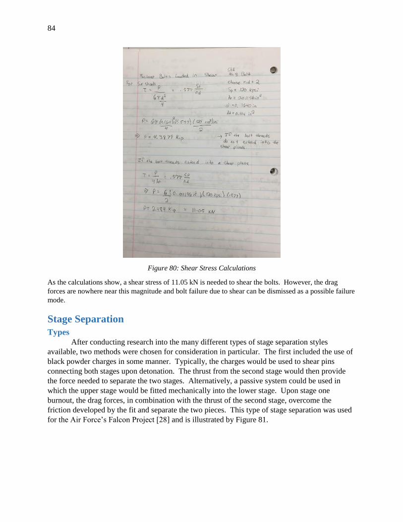
84
Figure 80: Shear Stress Calculations
As the calculations show, a shear stress of 11.05 kN is needed to shear the bolts. However, the drag
forces are nowhere near this magnitude and bolt failure due to shear can be dismissed as a possible failure
mode.
Stage Separation
Types
After conducting research into the many different types of stage separation styles
available, two methods were chosen for consideration in particular. The first included the use of
black powder charges in some manner. Typically, the charges would be used to shear pins
connecting both stages upon detonation. The thrust from the second stage would then provide
the force needed to separate the two stages. Alternatively, a passive system could be used in
which the upper stage would be fitted mechanically into the lower stage. Upon stage one
burnout, the drag forces, in combination with the thrust of the second stage, overcome the
friction developed by the fit and separate the two pieces. This type of stage separation was used
for the Air Force’s Falcon Project [28] and is illustrated by Figure 81.
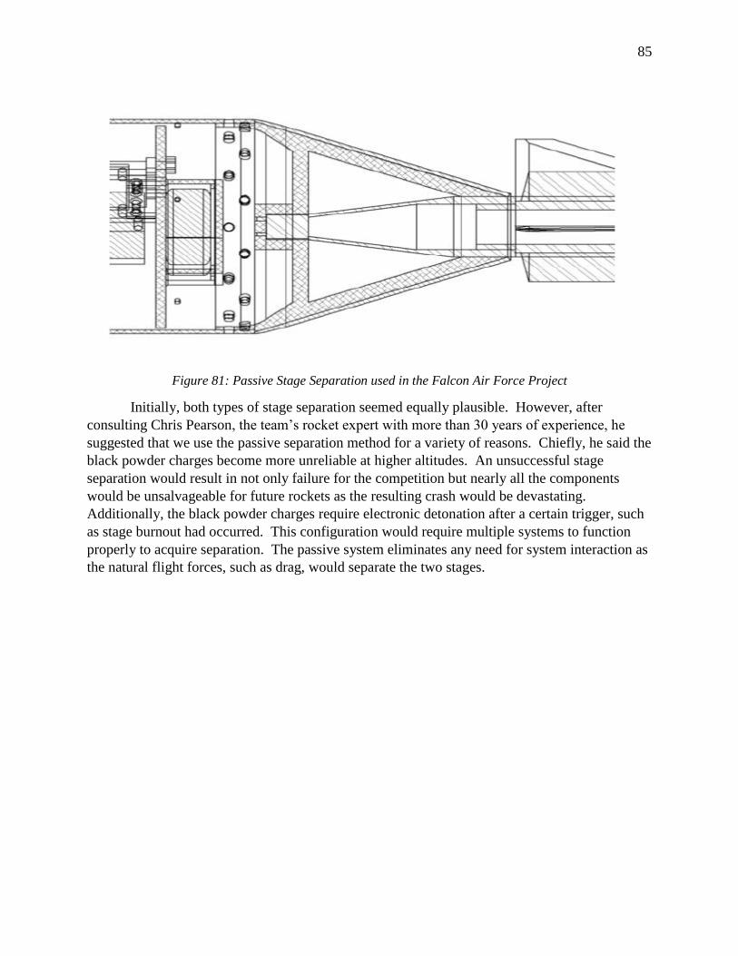
85
Figure 81: Passive Stage Separation used in the Falcon Air Force Project
Initially, both types of stage separation seemed equally plausible. However, after
consulting Chris Pearson, the team’s rocket expert with more than 30 years of experience, he
suggested that we use the passive separation method for a variety of reasons. Chiefly, he said the
black powder charges become more unreliable at higher altitudes. An unsuccessful stage
separation would result in not only failure for the competition but nearly all the components
would be unsalvageable for future rockets as the resulting crash would be devastating.
Additionally, the black powder charges require electronic detonation after a certain trigger, such
as stage burnout had occurred. This configuration would require multiple systems to function
properly to acquire separation. The passive system eliminates any need for system interaction as
the natural flight forces, such as drag, would separate the two stages.
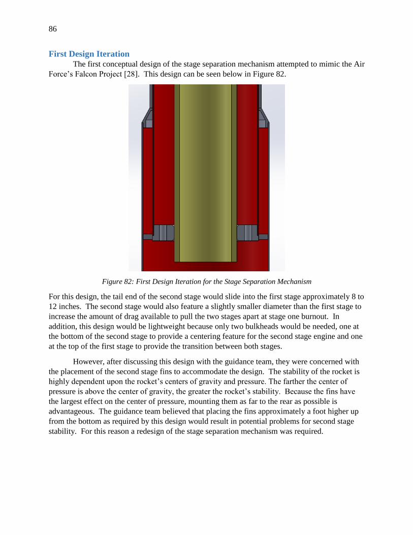
86
First Design Iteration
The first conceptual design of the stage separation mechanism attempted to mimic the Air
Force’s Falcon Project [28]. This design can be seen below in Figure 82.
Figure 82: First Design Iteration for the Stage Separation Mechanism
For this design, the tail end of the second stage would slide into the first stage approximately 8 to
12 inches. The second stage would also feature a slightly smaller diameter than the first stage to
increase the amount of drag available to pull the two stages apart at stage one burnout. In
addition, this design would be lightweight because only two bulkheads would be needed, one at
the bottom of the second stage to provide a centering feature for the second stage engine and one
at the top of the first stage to provide the transition between both stages.
However, after discussing this design with the guidance team, they were concerned with
the placement of the second stage fins to accommodate the design. The stability of the rocket is
highly dependent upon the rocket’s centers of gravity and pressure. The farther the center of
pressure is above the center of gravity, the greater the rocket’s stability. Because the fins have
the largest effect on the center of pressure, mounting them as far to the rear as possible is
advantageous. The guidance team believed that placing the fins approximately a foot higher up
from the bottom as required by this design would result in potential problems for second stage
stability. For this reason a redesign of the stage separation mechanism was required.
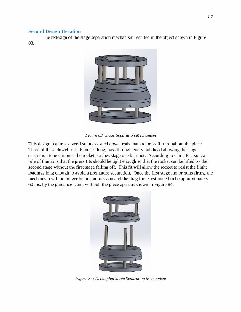
87
Second Design Iteration
The redesign of the stage separation mechanism resulted in the object shown in Figure
83.
Figure 83: Stage Separation Mechanism
This design features several stainless steel dowel rods that are press fit throughout the piece.
Three of these dowel rods, 6 inches long, pass through every bulkhead allowing the stage
separation to occur once the rocket reaches stage one burnout. According to Chris Pearson, a
rule of thumb is that the press fits should be tight enough so that the rocket can be lifted by the
second stage without the first stage falling off. This fit will allow the rocket to resist the flight
loadings long enough to avoid a premature separation. Once the first stage motor quits firing, the
mechanism will no longer be in compression and the drag force, estimated to be approximately
60 lbs. by the guidance team, will pull the piece apart as shown in Figure 84.
Figure 84: Decoupled Stage Separation Mechanism
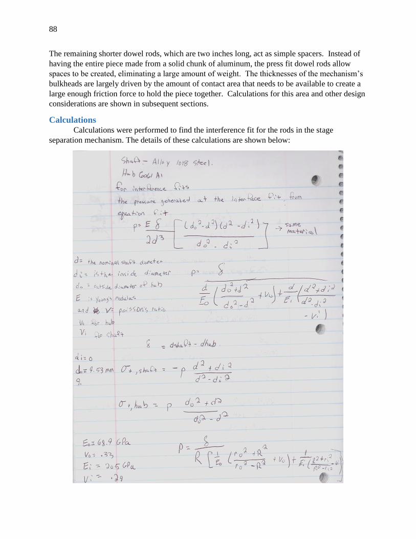
88
The remaining shorter dowel rods, which are two inches long, act as simple spacers. Instead of
having the entire piece made from a solid chunk of aluminum, the press fit dowel rods allow
spaces to be created, eliminating a large amount of weight. The thicknesses of the mechanism’s
bulkheads are largely driven by the amount of contact area that needs to be available to create a
large enough friction force to hold the piece together. Calculations for this area and other design
considerations are shown in subsequent sections.
Calculations
Calculations were performed to find the interference fit for the rods in the stage
separation mechanism. The details of these calculations are shown below:
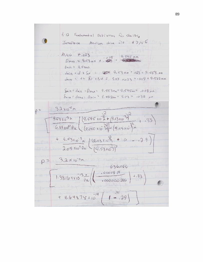
89
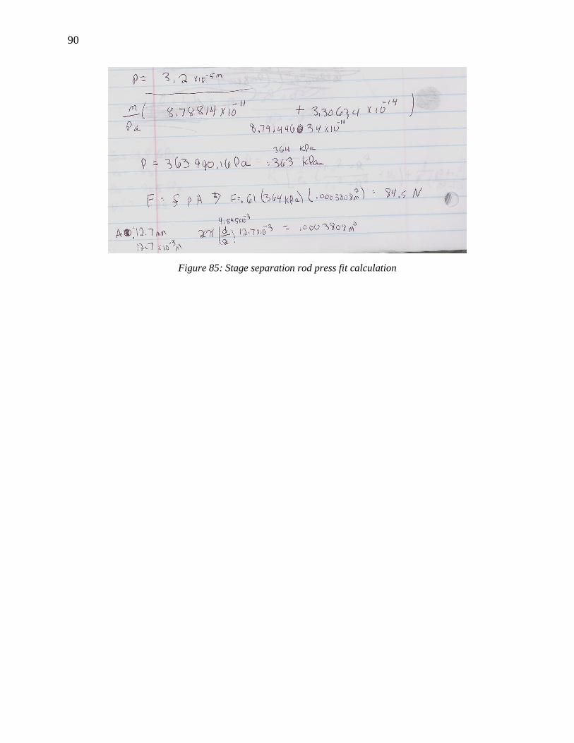
90
Figure 85: Stage separation rod press fit calculation
91
Manufacturing and Assembly
Manufacturing
Each of the bulkheads, rings, and propulsion pieces contained in the first and second
stage were student created in the University of Akron Mechanical Engineer Department’s
machine shop. Once the design of the first and second stage propulsion and structural
components was complete, part drawings were created for all parts that were intended to be
produced in house. The part drawings were given tolerances that were carefully considered to
achieve the desired types of fits in the assembly. The first stage prints were divided between
those intended for use with the commercial motor, and those intended for use with the custom
motor. Due to the short time available before competition and the extra complexity of some of
the custom motor parts, it was determined that the commercial motor parts would be made first
to ensure the rocket was competition ready. The custom parts would be attempted after the
commercial parts were complete if time permitted.
Because of their simple ring-shape and lack of advanced features, it was determined that
all the bulkheads and rings for the first and second stage commercial motor would be made in
house. These parts included:
1. Support block
2. Welded flange plate
3. 2 Fin support rings
4. Centering ring
5. Second stage bulkheads (6)
Once the six and five inch OD round stocks of 6061 T6 Aluminum were purchased, a plan for
the order of operations for manufacturing the parts was developed along with machine shop lead
Steve Gerbetz. The round stock itself was prepared for further processing by facing down one
end to a smooth, flat surface on the lathe. This ensures that there is one end of the round stock
that can seat flat in the chuck. Then, placing this flat end into the chuck, the other end was faced
to a smooth surface as well. This way, when the bandsaw is used to cut off a slice of the round
stock, one surface of the slice is already flat and suitable for the chuck.
As all the parts had similar overall shape, they all followed the same manufacturing steps:
1. The part thickness plus 1/8 inch was cut from the aluminum round stock on the bandsaw.
The extra 1/8 inch was intended to account for the saw not cutting perfectly vertically.
2. The flat end of the slice was placed into the chuck and the rough side was faced down
until the part reached its total desired thickness.
3. The location of the holes were laid out with scribing tools.
4. Any holes were drilled on the drill press, and then tapped if needed.
5. The part was placed back on the lathe to turn out the inner bore to a high degree of
precision.
When drilling through holes, all parts that had common hole sets were clamped together and
drilled at the same time. This ensured that even if the holes weren’t drilled completely straight,
they would still all line up between parts.
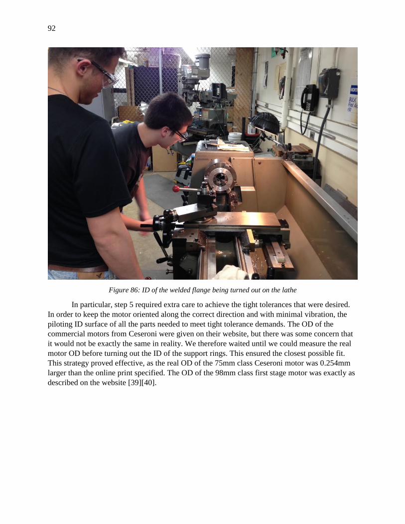
92
Figure 86: ID of the welded flange being turned out on the lathe
In particular, step 5 required extra care to achieve the tight tolerances that were desired.
In order to keep the motor oriented along the correct direction and with minimal vibration, the
piloting ID surface of all the parts needed to meet tight tolerance demands. The OD of the
commercial motors from Ceseroni were given on their website, but there was some concern that
it would not be exactly the same in reality. We therefore waited until we could measure the real
motor OD before turning out the ID of the support rings. This ensured the closest possible fit.
This strategy proved effective, as the real OD of the 75mm class Ceseroni motor was 0.254mm
larger than the online print specified. The OD of the 98mm class first stage motor was exactly as
described on the website [39][40].
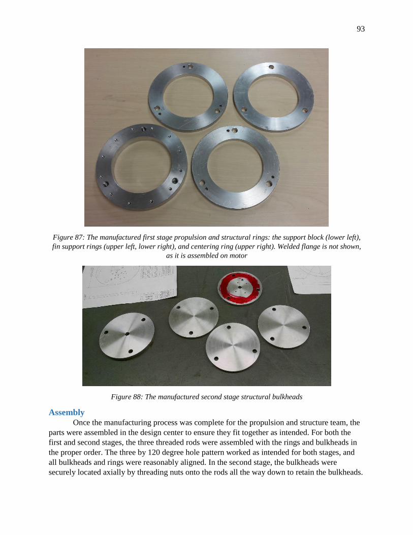
93
Figure 87: The manufactured first stage propulsion and structural rings: the support block (lower left),
fin support rings (upper left, lower right), and centering ring (upper right). Welded flange is not shown,
as it is assembled on motor
Figure 88: The manufactured second stage structural bulkheads
Assembly
Once the manufacturing process was complete for the propulsion and structure team, the
parts were assembled in the design center to ensure they fit together as intended. For both the
first and second stages, the three threaded rods were assembled with the rings and bulkheads in
the proper order. The three by 120 degree hole pattern worked as intended for both stages, and
all bulkheads and rings were reasonably aligned. In the second stage, the bulkheads were
securely located axially by threading nuts onto the rods all the way down to retain the bulkheads.
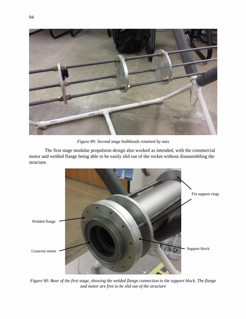
94
Figure 89: Second stage bulkheads retained by nuts
The first stage modular propulsion design also worked as intended, with the commercial
motor and welded flange being able to be easily slid out of the rocket without disassembling the
structure.
Figure 90: Rear of the first stage, showing the welded flange connection to the support block. The flange
and motor are free to be slid out of the structure
Fin support rings
Support block
Welded flange
Cesaroni motor
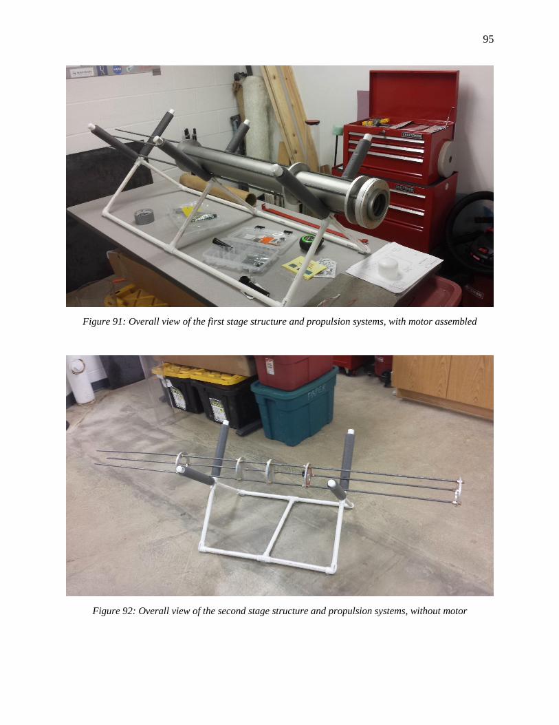
95
Figure 91: Overall view of the first stage structure and propulsion systems, with motor assembled
Figure 92: Overall view of the second stage structure and propulsion systems, without motor
96
Rocket Team Experience Challenges
System Interfacing
One of the main challenges encountered while working for the rocket team was the
interactions and communication between systems. This proved to be a particular challenge for
the structure team because of their centralized role in tying all other structures together. All of
the other systems interact directly with the structure in some manner. For this reason the design
of the structure was heavily influenced by all of the other systems. Open and constant dialogue
was needed in order for the interfaces and the structure itself to work and support all of the
necessary components. However, many times throughout the design process communication
broke down and the design of the structure became orders of magnitude harder. Educated
guesses had to be made in many instances to keep making progress in the design. This lack of
communication also increased the friction amongst design teams as other groups would become
upset as a sudden redesign was required to fit our changes. From the propulsion team’s
perspective, many of these same issues were common and not addressed. This caused ongoing
delays as equations could not be solved without making guesses. Some examples of problems
encountered when interfacing between other systems are given below.
Inertial loadings are found when the weights are known. These weights play into
calculating the shear and moments of the rocket, which are crucial to determining if the structure
is going to fail during launch, flight or landing. Unfortunately, the process was to guess
everything that was going inside the rocket, designing a structure around those guesses, and
when new information came to us we had to account for the changes that were needed to keep
other teams from redesigning.
Not all teams were as big of challenges as others but nonetheless the process was still
discouraging when parts had to be reworked. For instance, the avionics bay is a simple section.
The design process only required the use of two mounts and the duty of the structure team was to
create a bulkhead that was able to mount the electronics board and CO2 canisters used to deploy
the parachute. To accomplish this task, a part that had drill holes on the faces of the bulkheads
worked well. The electronics portion of the avionics bay is not directly attached to the structure
of the rocket so the only design elements considered for the electronics was leaving them the
ability to string wires throughout the inside of the body. As long as the components have a few
hundredths of an inch between them and the skin the rocket the cords could be strung through
without drilling holes for them to travel through.
Other systems such the launch pad team have not even given a plan of attaching their
system to the structure. The structure team has met with the launch pad team over the months to
get information from them, but until recently they were still in the process of designing the shape
and dimensions etc. of the launch pad. They have provided this design and have shown the ideas
of how the launch rails will attach to the structure, but they have not given any calculations
supporting the work. When questions are asked concerning these matters little response has been
given, and lack of participation at team meetings by this group has led to further questions by the
structure team.
97
The payload team has still not given the structure team a clear plan on how they plan to
attach their component to the inside of the rocket. April was the first month that the team even
saw a model of what the part was going to look like. The part has to allow air sample collections
to flow into it during the descent of the rocket. In some way there must be ports on the skin of
the body which allows the air to flow in and be collected. However, the port must also not allow
the air to flow in until the descent so that the data results are not skewed. The structure and
propulsion teams have voiced their concerns given the quickly approaching time deadlines that
the project currently has. The structure team is unsure, depending on the payload’s design, if they
will be able to make modifications to support system, with the amount of time that is left until
competition.
The final system that is a concern is the guidance team. The guidance team is responsible
for the fin and nose cone designs. For several months the guidance team has been spending their
time running computational fluid dynamics analyses on an array of fin geometries. There is no
problem with running these optimizing programs to get a design that will perform optimally for
our system, but time quotas need to be met. Into the month of April the fins still have not been
constructed. The plan conceived by the propulsion and structure teams was to weld the fins into a
“fin basket,” as seen in Figure 36. A weld would provide stability to the fins in flight and prevent
any chance that the fins could tear off during flight due to aerodynamic loadings. The guidance
team has still not given drawings of a finished nose cone either.
The propulsion and structure teams, on the other hand, tended to have a much more
cooperative relationship. From the early stages, the importance of considering the
propulsion/structure connection were made clear, and an effort was made between some of the
designers to meet early and often to make sure the designs remained compatible. This
constructive communication has resulted in the successful assembly between the manufactured
propulsion and structural systems, which, at the time of this writing, are still the only completed
systems assembled to the rocket.
Issues Encountered
Communication issues were just the first of a few core problems. The first problem was
the lack of standards across all design teams. Although the SI system of units was chosen to be
used as a team standard, there was a lack of discipline among teams in putting those units to
use. Some teams decided Imperial units were more convenient and used those anyway. The lack
of consistency led to many unnecessary conversions having to take place during discussions or
other design work increasing errors and wasting time. Along this same vein was the lack of
common design software. Even though the team was sponsored by Solidworks, several team
members used Creo, Inventor or some other type of software in design. This created problems in
sharing drawings as the files would have to be converted and saved locally in order to be
used. For this reason several different versions of the same part existed on multiple computers
increasing the difficulty of keeping track of which one was correct and the most up to
date. Furthermore, Google Drive, which was used as the file sharing platform, was under-
utilized by many of the design teams who failed to upload their local files or update the existing
files on a regular basis.
98
A second core problem was lack of commitment to the final goal of completing a rocket.
This particular problem manifested in multiple ways, the first being attendance. At the
beginning of the year there were over 20 people on the structure team and over 100 on the rocket
team in total. However, as the year went on total attendance to meetings and other events
quickly dwindled. By the end of the year the structure team consisted of only three
members. Total rocket team attendance was approximately 30. The leadership of the recovery
system was also in flux for most of the design period as the lead role changed three times before
a replacement was ultimately found. The inconsistency of team members increased the difficulty
of collaboration among teams as well as the ability of the team lead to delegate tasks to other
members. Along this same topic was the misallocation of senior leadership to the overall rocket
design. Of all the seniors on the team, only a few selected the rocket as a senior design. For this
reason the rocket was an extra-curricular activity for many and it took less importance to work,
class, or the other design project the student was involved in.
Proposed Solutions To correct the problems outlined, the following proposals could be implemented. First,
the person who is placed in the Team Coordinator position must instill unit and design software
discipline among the different systems. As the Team Coordinator, this person’s job is to be a
facilitator between teams and make sure the projects are on track. This person could easily be
used as an enforcer to check that each team is utilizing common units and software to eliminate
problems.
Improving the file sharing system could also be accomplished relatively easily. At the
conclusion of team meetings, the leader of each system should be required to upload all of their
current files to the google drive. This process would force everyone to utilize the file sharing
system as well as ensure that all of the files shared are updated. A common file naming
convention could also be proposed so that team members unfamiliar with a particular system
could easily locate files that they need to use.
Solving the commitment type problems would be much more difficult. The easiest step
would be to dictate that all seniors on the rocket team must use some component on the
competition rocket as their senior design. This is a particularly efficient solution because seniors
have the most engineering knowledge as well as having a portion of their schedule dedicated
solely to the rocket design. Motivation to finish the project is also built into the solution because
the seniors have to finish their design in order to graduate. The project is more than an
extracurricular activity that can be worked on whenever time permits. To improve participation
among under classmen, I propose that the design team can be used for class credit. The
curriculum already requires a mechanical engineering design elective. A full year on one of the
design teams could count toward meeting this requirement. To be eligible for credit, the student
would have to report to the team adviser and complete some sort of design. This proposal would
again transform the rocket team from simply an extracurricular activity to a class room project
which would force students to complete their work.

99
References [1] https://en.wikipedia.org/wiki/Rocket_engine_nozzle#cite_note-7
[2] Huzel, D. K. and Huang, D. H. (1971). NASA SP-125, Design of Liquid Propellant Rocket
Engines (2nd Edition ed.). NASA
[3] http://www.k-makris.gr/RocketTechnology/Nozzle_Design/nozzle_design.htm
[4] Sutton, George Paul., and Oscar Biblarz. "Propellant Burning Rate." P.437. Rocket
Propulsion Elements. New York: John Wiley & Sons, 2001. N. pag. Print.
[5] “Rocket Thrust Summary”; http://www.grc.nasa.gov/WWW/k-12/airplane/rktthsum.html
[6] “Solid Rocket Motor Theory – Propellant Grain” http://www.nakka-rocketry.net/
th_grain.html
[7] http://openrocket.sourceforge.net/
[8] http://openrocket.sourceforge.net/features.html
[9] http://www.burnsim.com/
[10] Blazanin, Tom. "NEW TO BURNSIM? OLD USER AND STILL CONFUSED? THIS
WILL HELP." Tripoli Gerlach Research Rocketry News 4.3 (2014): 7-10. Web. 23 Apr. 2015.
[11] “Solid Rocket Motor Theory -- Impulse and C-star”; http://www.nakka-rocketry.net/
th_imp.html
[12] http://en.wikipedia.org/wiki/Specific_impulse
[13] “Fins for Rocket Stability”; http://www.nakka-rocketry.net/fins.html
[14] “Weather Cocking”; http://exploration.grc.nasa.gov/education/rocket/rktcock.html
[15] “Solid Rocket Motor Theory -- Nozzle Theory”; http://www.nakka-rocketry.net/
th_nozz.html
[16] Munson, Bruce Roy, T. H. Okiishi, Wade W. Huebsch, and Alric P. Rothmayer.
Fundamentals of Fluid Mechanics. Hoboken, NJ: John Wiley & Sons, 2013. Print.
[17] “Solid Rocket Motor Theory -- Chamber Pressure”; http://www.nakka-rocketry.net/
th_pres.html
[18] http://en.wikipedia.org/wiki/Tsiolkovsky_rocket_equation
[19] https://lokiresearch.com/secure/store.asp?groupid=6112003225363
[20] Budynas, Richard G., J. Keith. Nisbett, and Joseph Edward. Shigley. Shigley's Mechanical
Engineering Design. New York: McGraw-Hill, 2011. Print.
[21] Sutton, George Paul., and Oscar Biblarz. "Burning Rate Relation with Pressure." P.428.
Rocket Propulsion Elements. New York: John Wiley & Sons, 2001. N. pag. Print.
100
[22] http://space.stackexchange.com/questions/1171/efficient-types-of-nozzles-used-in-rockets
[23] http://beta.lokiresearch.com/specials.aspx
[24] http://www.rocketsaway.com/
[25] http://www.smalley.com/retaining-rings/spirolox
[26] http://www.hobartbrothers.com/downloads/aluminum_filler__eNttQ.pdf
[27] http://www.pro38.com/products/pro98/motor.php
[28] Comer, A.L., “Loading and Stress Analysis for Hypersonic Flight Conditions of Falcon
Launch VII,” USAF Academy, Colorado Springs, CO.
[29] Box, S., Bishop, C. M., and Hunt, H., 2009, “Estimating the Dynamic and Aerodynamic
Parameters of Passively Controlled High Power Rockets for Flight Simulation,” Cambridge
Rocketry.
[30] 2015, “Screw Thread Design,” from https://www.fastenal.com/en/78/screw-thread-design
[31] Boynton, R. and Wiener, K., “How to Calculate Mass Properties (An Engineer’s Practical
Guide),” Space Electronics, Inc., Berlin, CT.
[32] Newlands, R. and Heywood, M., 2011, “Rocket Vehicle Loads and Airframe Design,”
Aspire Space.
[33] Newlands, R., 2011, “Rocketry Aerodynamics,” Aspire Space.
[34] Niskanen, S., 2009, “Development of an Open Source Model Rocket Simulation Software,”
Master’s thesis, Department of Information and Natural Sciences, Helsinki University of
Technology.
[35] Bruhn, E.F., 1973, Analysis and Design of Flight Vehicle Structures, Jacobs Publishing.
[36] Budynas, R. G. and Nisbett, J. K., 2011, Shigley’s Mechanical Engineering Design, 9th ed.,
McGraw-Hill, New York, New York.
[37] Hibbeler, R.C., 2010, Engineering Mechanics: Statics, 12th ed., Pearson Prentice Hall,
Upper Saddle River, New Jersey.
[38] Hibbeler, R.C., 2011, Mechanics of Materials, 8th ed., Pearson Prentice Hall, Upper Saddle
River, New Jersey.
[39] http://www.pro38.com/pdfs/Pro98_dimensions.pdf
[40] http://www.pro38.com/pdfs/Pro75_dimensions.pdf
[41] http://www.mcmaster.com/
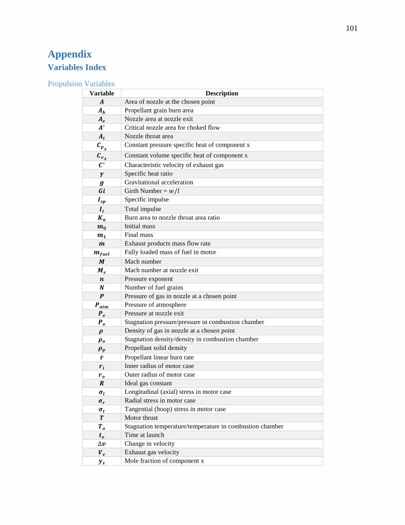
101
Appendix
Variables Index
Propulsion Variables
Variable Description
𝑨 Area of nozzle at the chosen point
𝑨𝒃 Propellant grain burn area
𝑨𝒆 Nozzle area at nozzle exit
𝑨∗ Critical nozzle area for choked flow
𝑨𝒕 Nozzle throat area
𝑪𝒑𝒙 Constant pressure specific heat of component x
𝑪𝒗𝒙 Constant volume specific heat of component x
𝑪∗ Characteristic velocity of exhaust gas
𝜸 Specific heat ratio
𝒈 Gravitational acceleration
𝑮𝒊 Girth Number = 𝑤/𝑙
𝑰𝒔𝒑 Specific impulse
𝑰𝒕 Total impulse
𝑲𝒏 Burn area to nozzle throat area ratio
𝒎𝟎 Initial mass
𝒎𝟏 Final mass
�̇� Exhaust products mass flow rate
𝒎𝒇𝒖𝒆𝒍 Fully loaded mass of fuel in motor
𝑴 Mach number
𝑴𝒆 Mach number at nozzle exit
𝒏 Pressure exponent
𝑵 Number of fuel grains
𝑷 Pressure of gas in nozzle at a chosen point
𝑷𝒂𝒕𝒎 Pressure of atmosphere
𝑷𝒆 Pressure at nozzle exit
𝑷𝒐 Stagnation pressure/pressure in combustion chamber
𝝆 Density of gas in nozzle at a chosen point
𝝆𝒐 Stagnation density/density in combustion chamber
𝝆𝒑 Propellant solid density
�̇� Propellant linear burn rate
𝒓𝒊 Inner radius of motor case
𝒓𝒐 Outer radius of motor case
𝑹 Ideal gas constant
𝝈𝒍 Longitudinal (axial) stress in motor case
𝝈𝒓 Radial stress in motor case
𝝈𝒕 Tangential (hoop) stress in motor case
𝑻 Motor thrust
𝑻𝒐 Stagnation temperature/temperature in combustion chamber
𝒕𝒐 Time at launch
∆𝒗 Change in velocity
𝑽𝒆 Exhaust gas velocity
𝒚𝒙 Mole fraction of component x
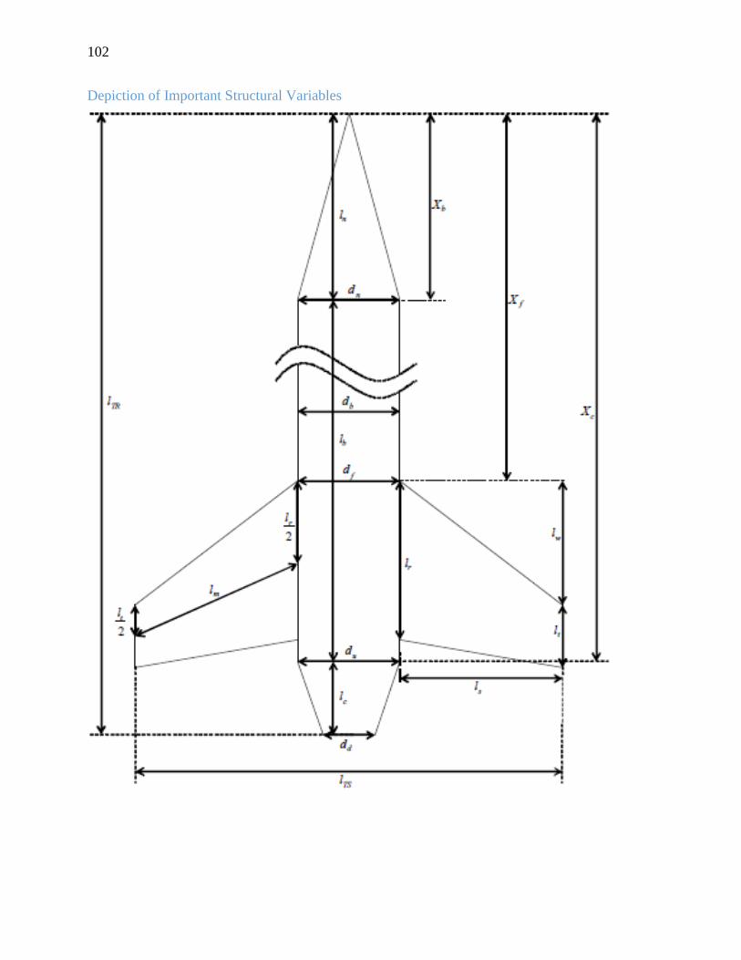
102
Depiction of Important Structural Variables
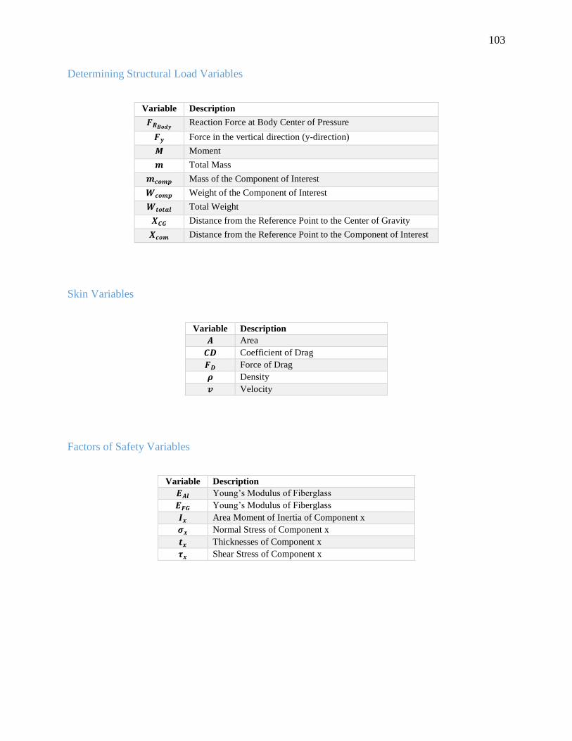
103
Determining Structural Load Variables
Variable Description
𝑭𝑹𝑩𝒐𝒅𝒚 Reaction Force at Body Center of Pressure
𝑭𝒚 Force in the vertical direction (y-direction)
𝑴 Moment
𝒎 Total Mass
𝒎𝒄𝒐𝒎𝒑 Mass of the Component of Interest
𝑾𝒄𝒐𝒎𝒑 Weight of the Component of Interest
𝑾𝒕𝒐𝒕𝒂𝒍 Total Weight
𝑿𝑪𝑮 Distance from the Reference Point to the Center of Gravity
𝑿𝒄𝒐𝒎 Distance from the Reference Point to the Component of Interest
Skin Variables
Variable Description
𝑨 Area
𝑪𝑫 Coefficient of Drag
𝑭𝑫 Force of Drag
𝝆 Density
𝒗 Velocity
Factors of Safety Variables
Variable Description
𝑬𝑨𝒍 Young’s Modulus of Fiberglass
𝑬𝑭𝑮 Young’s Modulus of Fiberglass
𝑰𝒙 Area Moment of Inertia of Component x
𝝈𝒙 Normal Stress of Component x
𝒕𝒙 Thicknesses of Component x
𝝉𝒙 Shear Stress of Component x
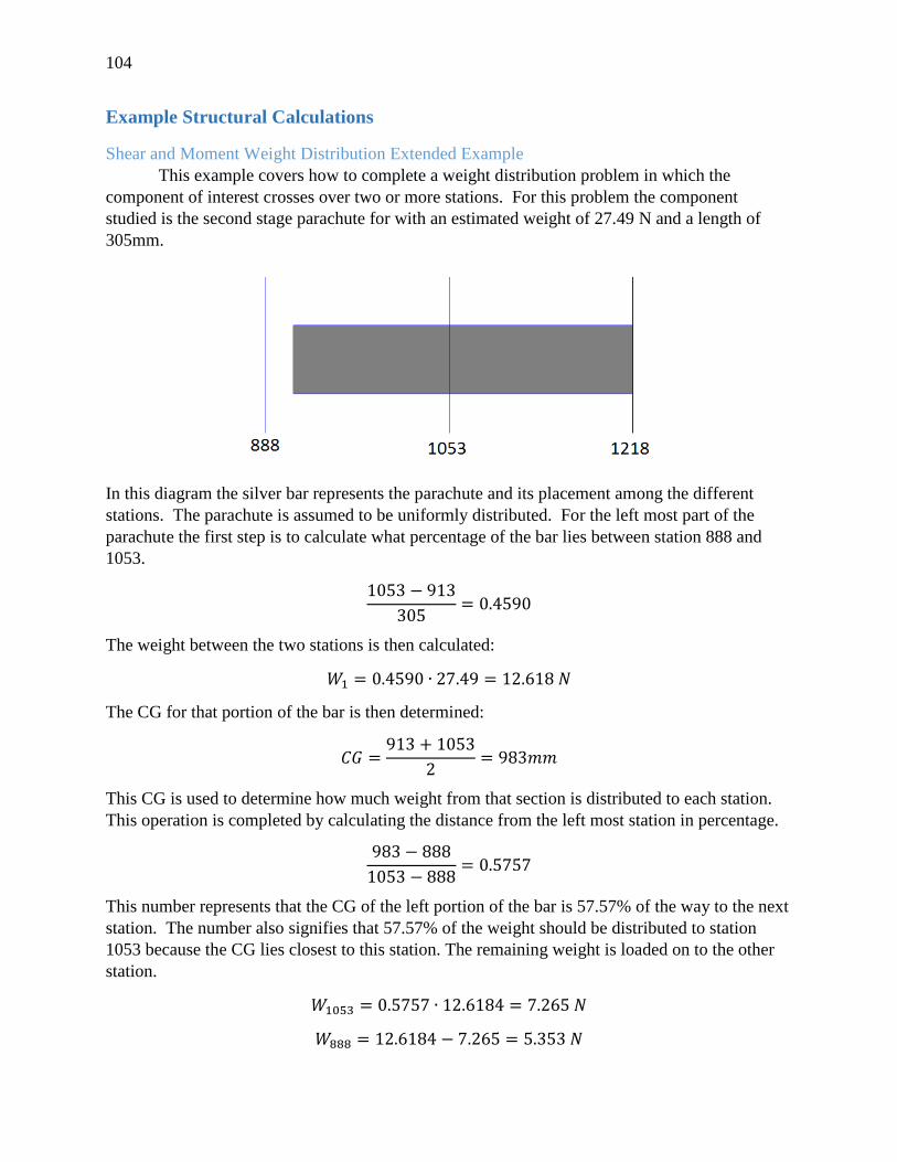
104
Example Structural Calculations
Shear and Moment Weight Distribution Extended Example
This example covers how to complete a weight distribution problem in which the
component of interest crosses over two or more stations. For this problem the component
studied is the second stage parachute for with an estimated weight of 27.49 N and a length of
305mm.
In this diagram the silver bar represents the parachute and its placement among the different
stations. The parachute is assumed to be uniformly distributed. For the left most part of the
parachute the first step is to calculate what percentage of the bar lies between station 888 and
1053.
1053 − 913
305= 0.4590
The weight between the two stations is then calculated:
𝑊1 = 0.4590 ∙ 27.49 = 12.618 𝑁
The CG for that portion of the bar is then determined:
𝐶𝐺 =913 + 1053
2= 983𝑚𝑚
This CG is used to determine how much weight from that section is distributed to each station.
This operation is completed by calculating the distance from the left most station in percentage.
983 − 888
1053 − 888= 0.5757
This number represents that the CG of the left portion of the bar is 57.57% of the way to the next
station. The number also signifies that 57.57% of the weight should be distributed to station
1053 because the CG lies closest to this station. The remaining weight is loaded on to the other
station.
𝑊1053 = 0.5757 ∙ 12.6184 = 7.265 𝑁
𝑊888 = 12.6184 − 7.265 = 5.353 𝑁
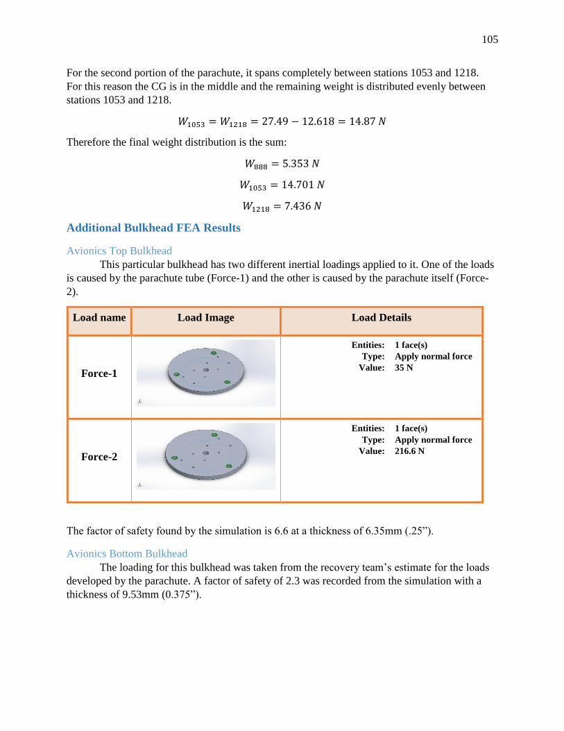
105
For the second portion of the parachute, it spans completely between stations 1053 and 1218.
For this reason the CG is in the middle and the remaining weight is distributed evenly between
stations 1053 and 1218.
𝑊1053 = 𝑊1218 = 27.49 − 12.618 = 14.87 𝑁
Therefore the final weight distribution is the sum:
𝑊888 = 5.353 𝑁
𝑊1053 = 14.701 𝑁
𝑊1218 = 7.436 𝑁
Additional Bulkhead FEA Results
Avionics Top Bulkhead
This particular bulkhead has two different inertial loadings applied to it. One of the loads
is caused by the parachute tube (Force-1) and the other is caused by the parachute itself (Force-
2).
Load name Load Image Load Details
Force-1
Entities: 1 face(s)
Type: Apply normal force
Value: 35 N
Force-2
Entities: 1 face(s)
Type: Apply normal force
Value: 216.6 N
The factor of safety found by the simulation is 6.6 at a thickness of 6.35mm (.25”).
Avionics Bottom Bulkhead
The loading for this bulkhead was taken from the recovery team’s estimate for the loads
developed by the parachute. A factor of safety of 2.3 was recorded from the simulation with a
thickness of 9.53mm (0.375”).
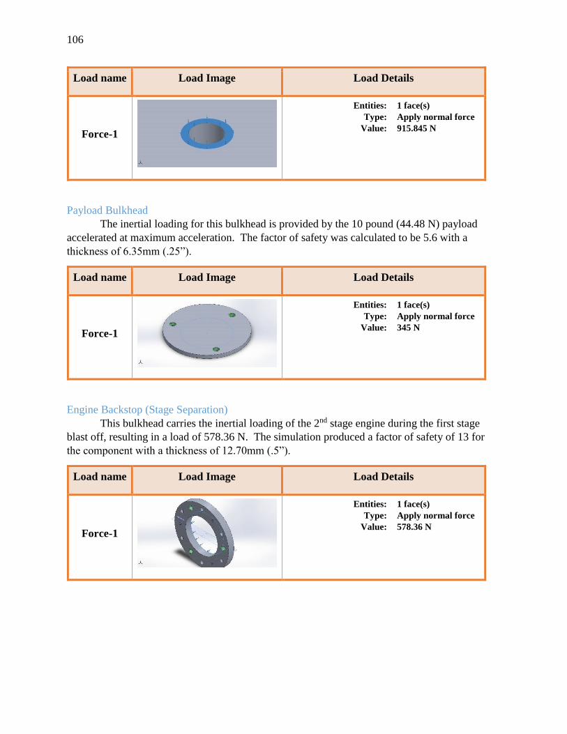
106
Load name Load Image Load Details
Force-1
Entities: 1 face(s)
Type: Apply normal force
Value: 915.845 N
Payload Bulkhead
The inertial loading for this bulkhead is provided by the 10 pound (44.48 N) payload
accelerated at maximum acceleration. The factor of safety was calculated to be 5.6 with a
thickness of 6.35mm (.25”).
Load name Load Image Load Details
Force-1
Entities: 1 face(s)
Type: Apply normal force
Value: 345 N
Engine Backstop (Stage Separation)
This bulkhead carries the inertial loading of the 2nd stage engine during the first stage
blast off, resulting in a load of 578.36 N. The simulation produced a factor of safety of 13 for
the component with a thickness of 12.70mm (.5”).
Load name Load Image Load Details
Force-1
Entities: 1 face(s)
Type: Apply normal force
Value: 578.36 N
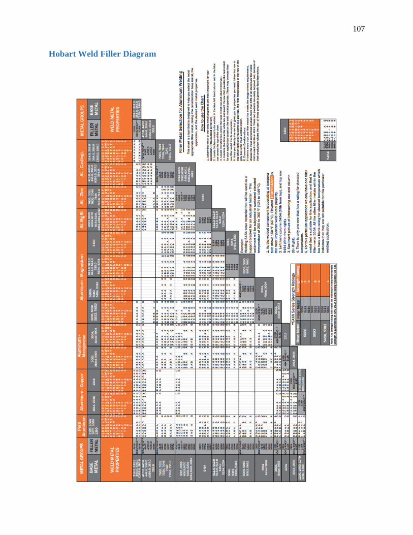
107
Hobart Weld Filler Diagram
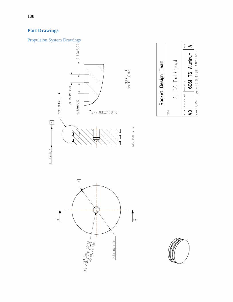
108
Part Drawings
Propulsion System Drawings
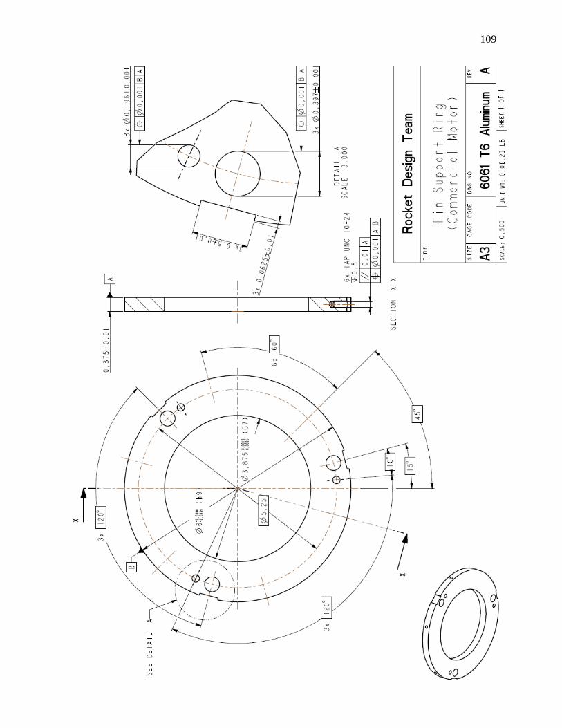
109
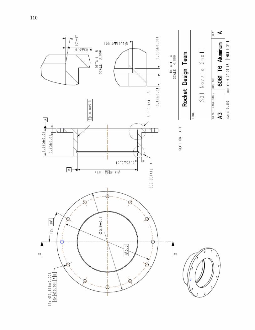
110
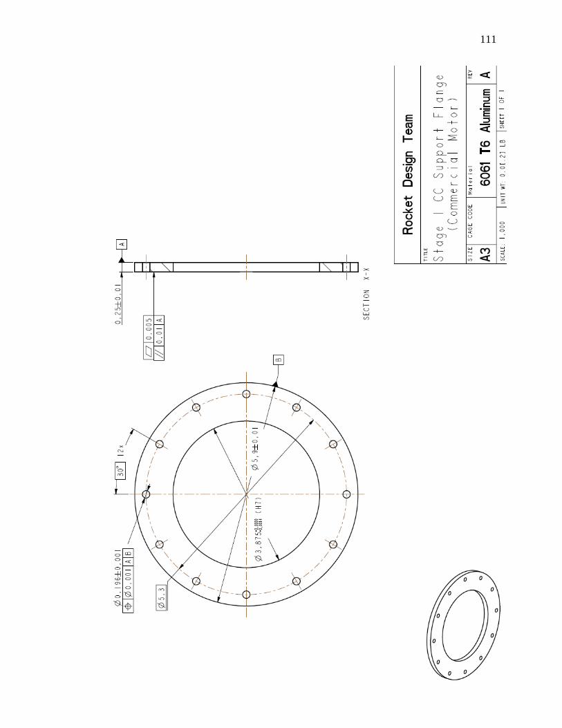
111
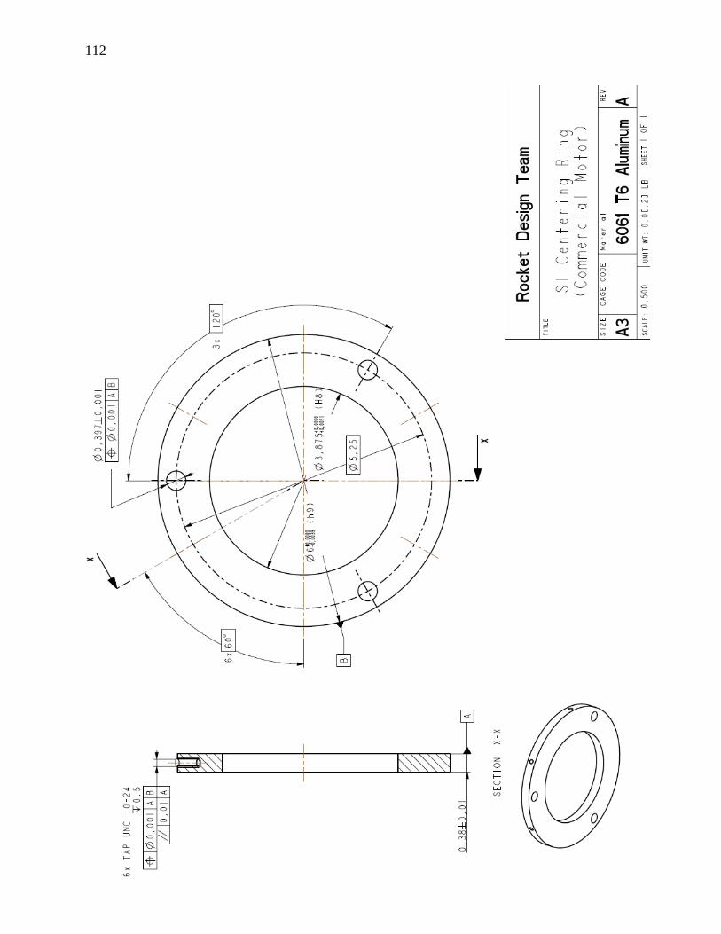
112
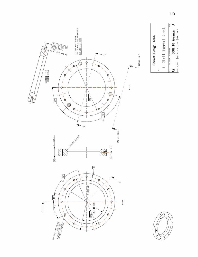
113
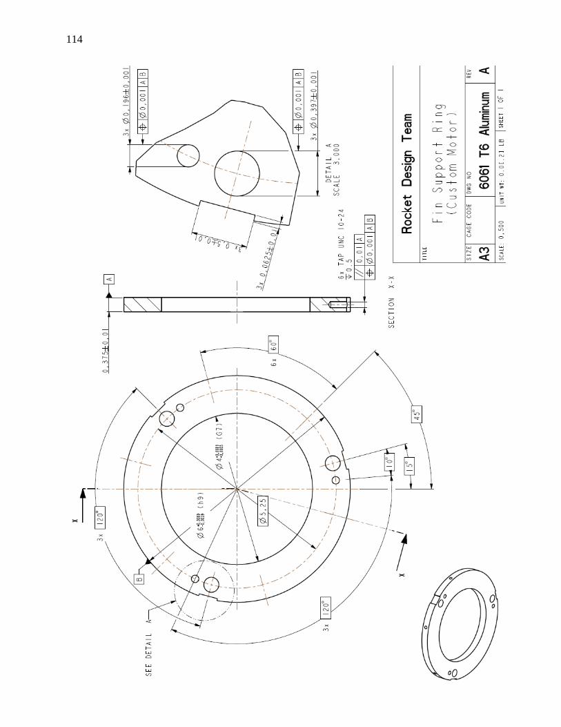
114
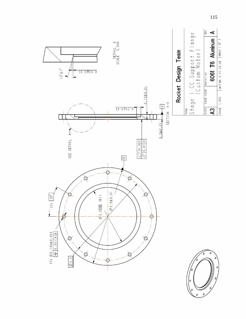
115
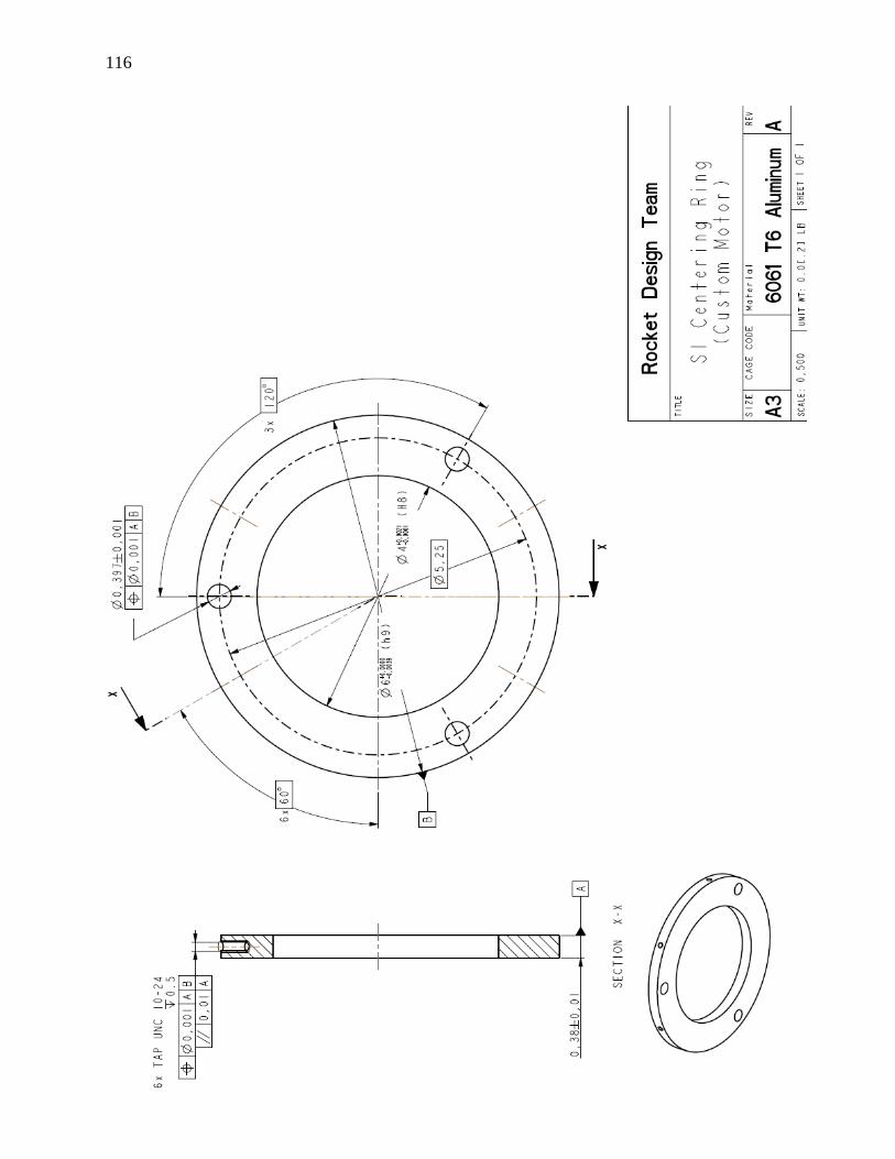
116
117
Structural System Drawings
118
119
120
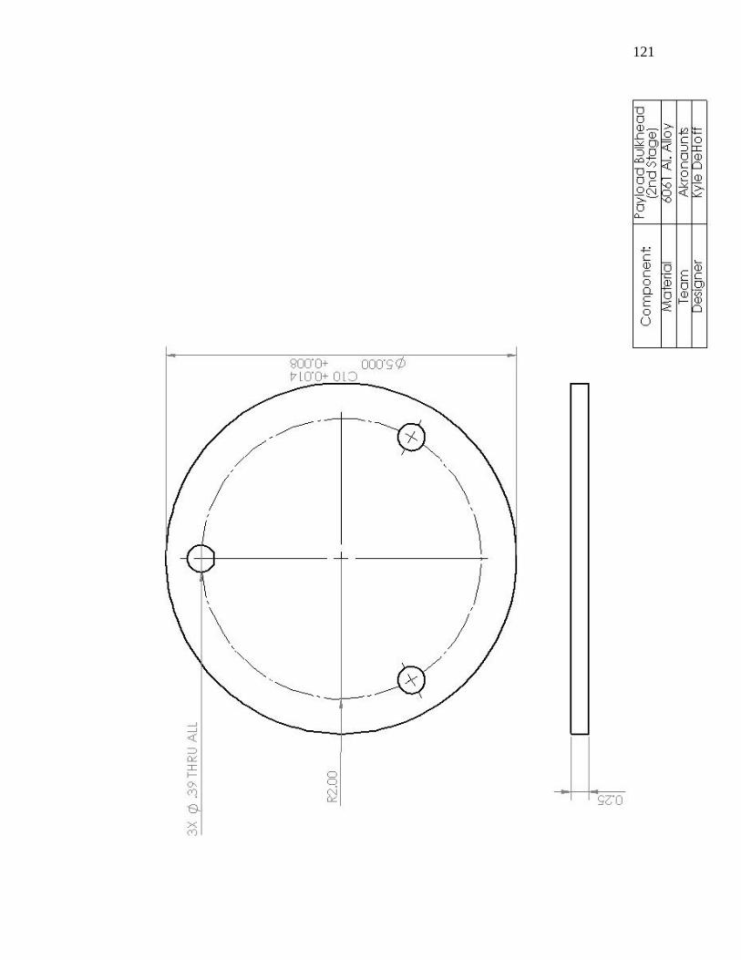
121
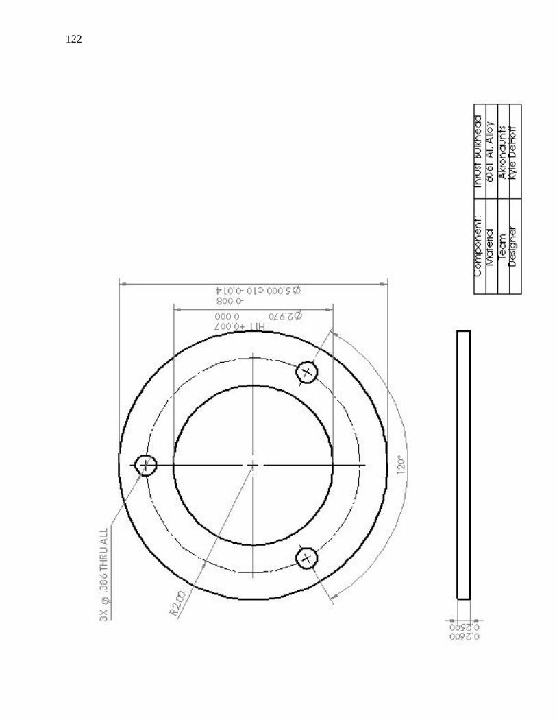
122
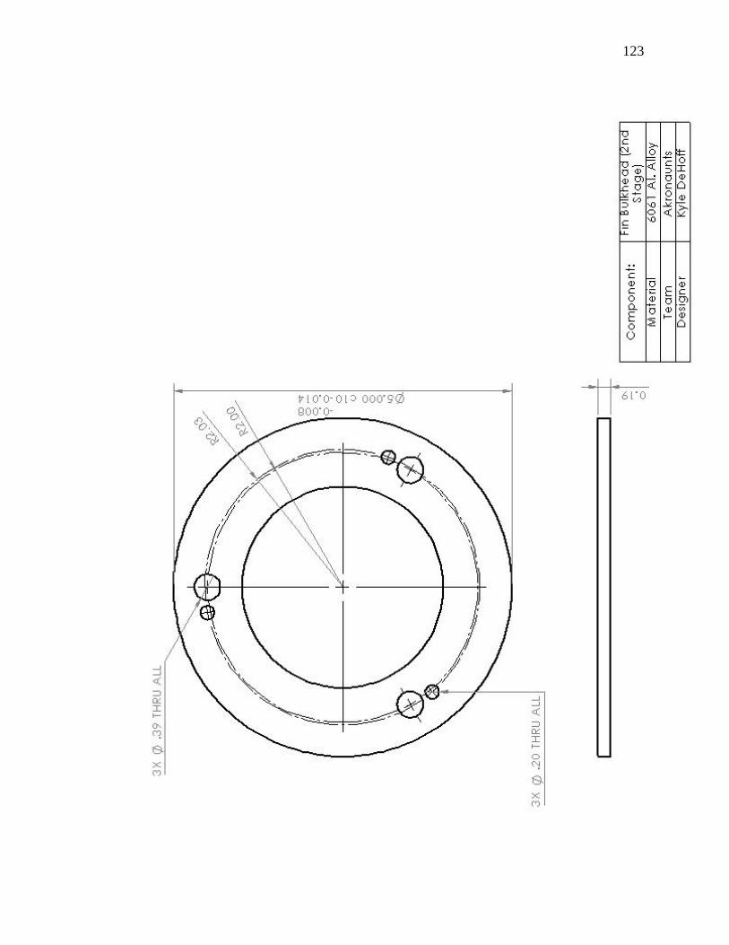
123
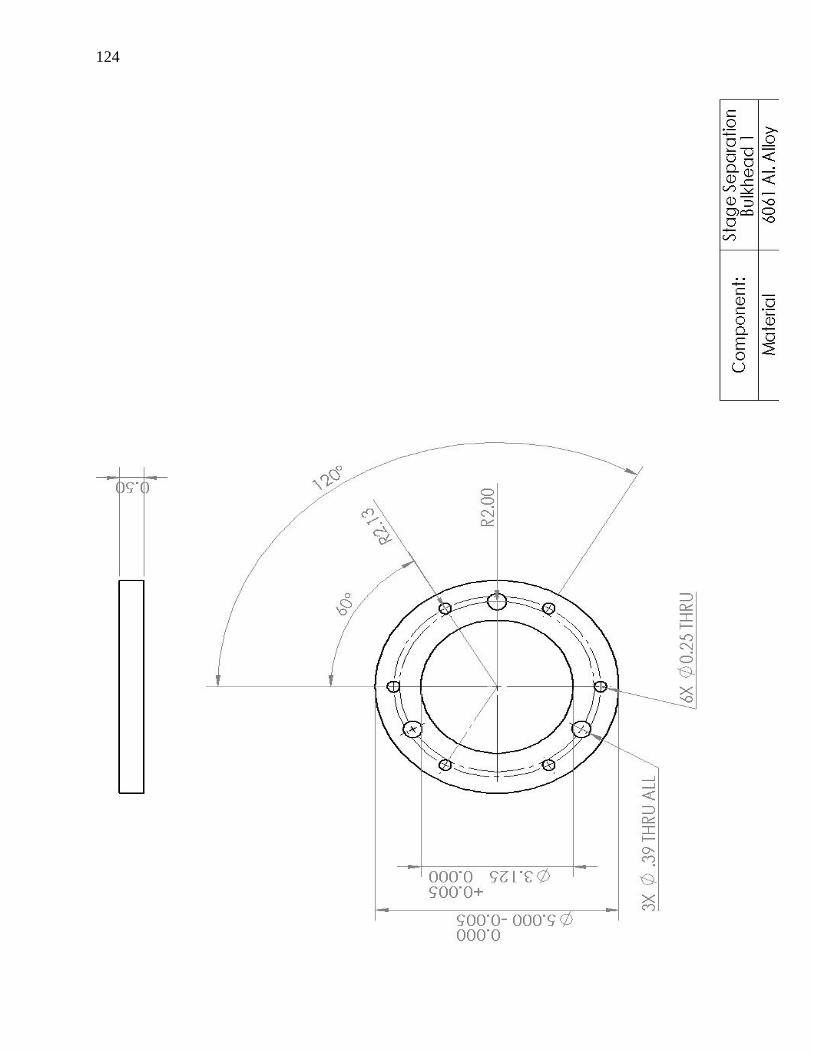
124
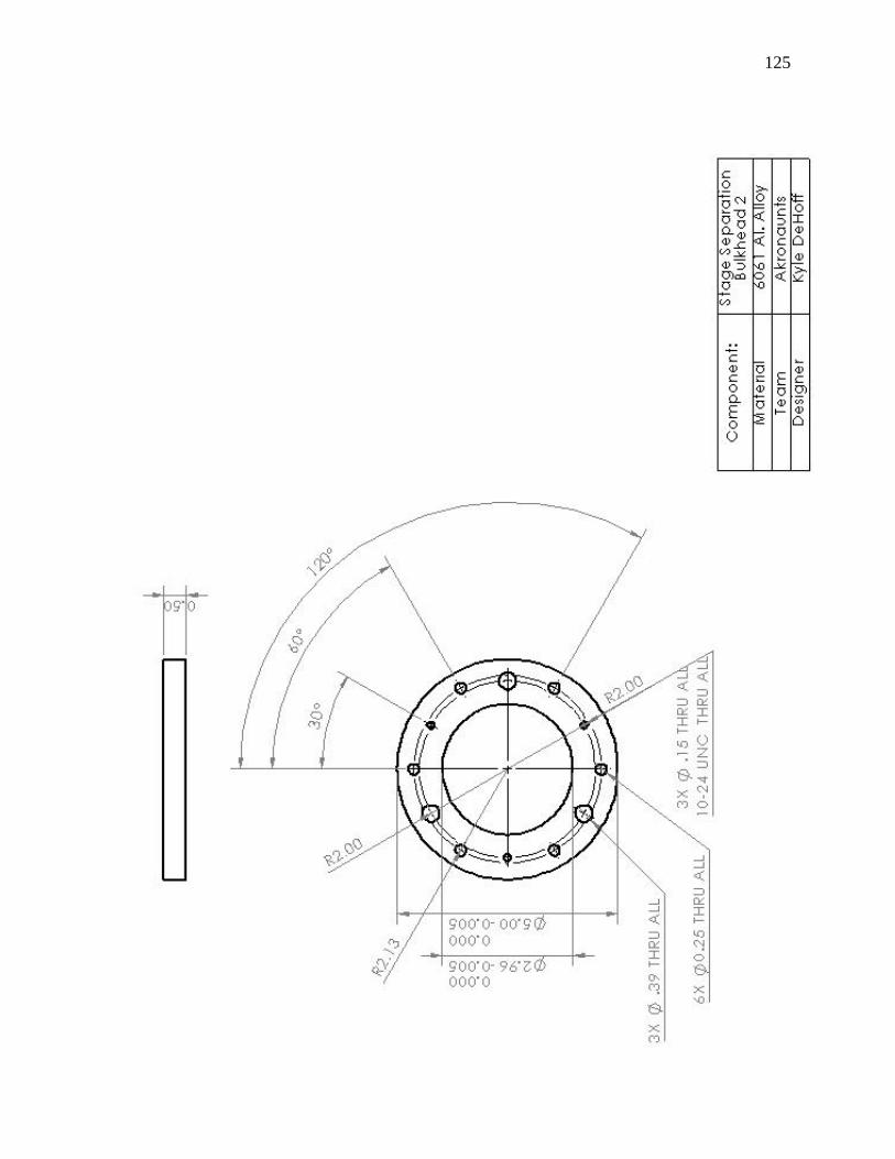
125
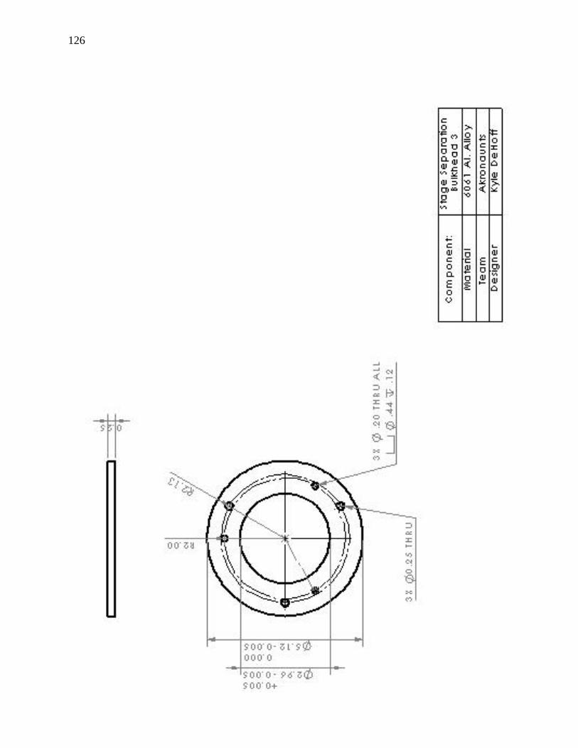
126
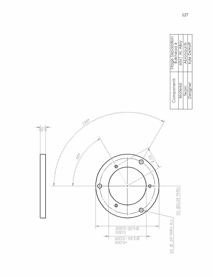
127