Embed Size (px)
Citation preview
Design of the ITER Magnets to Provide Plasma Operational Flexibility
N. Mitchell, D. Bessette, M. Ferrari, M. Huguet, C. Jong, Y. Takahashi, K. Yoshida 1)R. Maix 2)Y. Krivchenkov, E. Zapretilina 3)
1) ITER IT, Naka and Garching JWS2) ATI Atominstitut Wien, Austria3) Efremov Institute, St. Petersburg, Russia
(with slide contributions from J. Minervini, P. Lee, I. Rodin, P. Bruzzone)
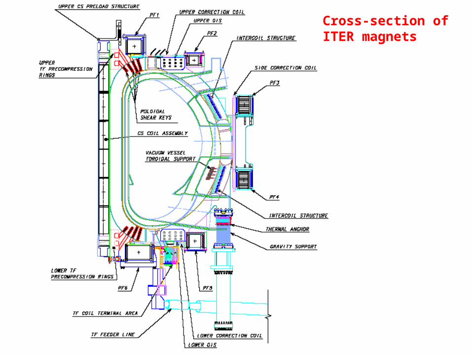
Cross-section of ITER magnets
Developments since 2001 (ITER Final Design Report)
Problems in 2001……..
Design in 2001 had a significant number of open options eg3 conductor/layouts for the CS, 2 for the TF2 concepts for the TF structures
Preparation of manufacturing specifications made difficult due to design uncertainty.
……………………….Solutions in 2004
Detailed investigations, negotiations with the ITER partners single agreed reference design.
Detailed design and analysis (mostly in the inner poloidal key region, in the TF cooling and nuclear shielding and the CCs) FLEXIBILITY to operate with a range of plasmas and cover uncertainties (in control, nuclear heating, plasma parameters)
No change to the cost or overall machine parameters
Limited time for talk pick out 4 examples in more detail
Main Work Areas
Design improvements to improve functionalityInner Poloidal KeysOuter OIS (friction joint)Central solenoid layout
Response to R&D resultsNb3Sn conductor
Optimisation to reduce costsTF Case fabrication routeCoil and structure cooling
Definition of Critical Components for ManufacturingCorrection coils
select 4 limited examples for presentation
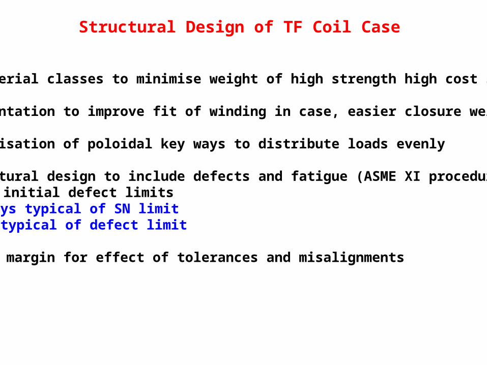
Structural Design of TF Coil Case
3 Material classes to minimise weight of high strength high cost steel
Segmentation to improve fit of winding in case, easier closure welds
Optimisation of poloidal key ways to distribute loads evenly
Structural design to include defects and fatigue (ASME XI procedures)SN and initial defect limits
Keyways typical of SN limitCase typical of defect limit
Leave margin for effect of tolerances and misalignments
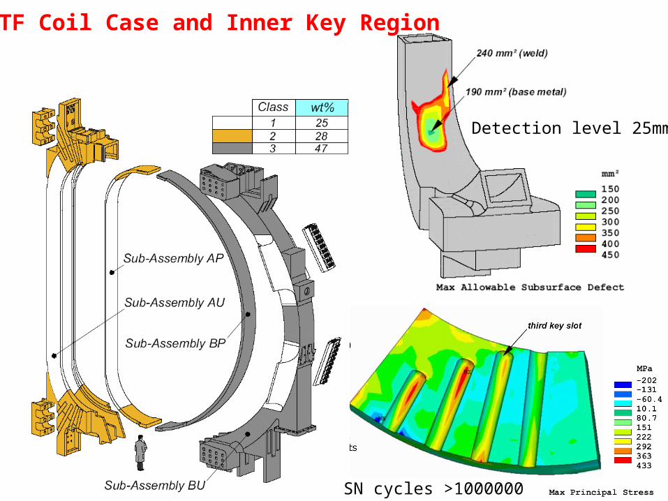
SN cycles >1000000
Detection level 25mm2
TF Coil Case and Inner Key Region
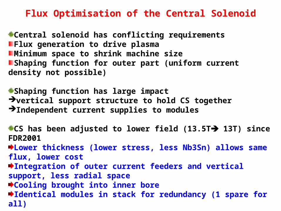
Flux Optimisation of the Central Solenoid
Central solenoid has conflicting requirementsFlux generation to drive plasmaMinimum space to shrink machine sizeShaping function for outer part (uniform current density not possible)
Shaping function has large impact vertical support structure to hold CS togetherIndependent current supplies to modules
CS has been adjusted to lower field (13.5T 13T) since FDR2001Lower thickness (lower stress, less Nb3Sn) allows same flux, lower
costIntegration of outer current feeders and vertical support, less radial
spaceCooling brought into inner boreIdentical modules in stack for redundancy (1 spare for all)
60
80
100
120
140
160
11 11.5 12 12.5 13 13.5 14 14.5
Tot
al W
eigh
t of
Nb3
Sn
Str
an
ds (
t)
Pre
bia
s F
lux
(Vs)
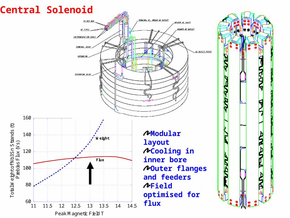
Peak Magnetic Field T
Weight
Flux
Central Solenoid
Modular layoutCooling in inner
boreOuter flanges
and feedersField optimised
for flux
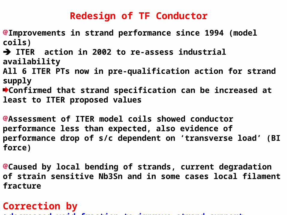
Redesign of TF Conductor
Improvements in strand performance since 1994 (model coils) ITER action in 2002 to re-assess industrial availability All 6 ITER PTs now in pre-qualification action for strand supply
Confirmed that strand specification can be increased at least to ITER proposed values
Assessment of ITER model coils showed conductor performance less than expected, also evidence of performance drop of s/c dependent on ‘transverse load’ (BI force)
Caused by local bending of strands, current degradation of strain sensitive Nb3Sn and in some cases local filament fracture
Correction bydecreased void fraction to improve strand supportsteel jacket to give overall compression, reduce number of filaments
going into tensionhigh performance strand to increase margins to allow for degradationLimit currents (and BI forces) in individual strands
0
200
400
600
800
1000
CS
MC
Sn
1
CS
MC
Br1
CS
MC
Br2
CS
MC
Sn
2
TF
CM
Sn
3
MT
18 S
n4
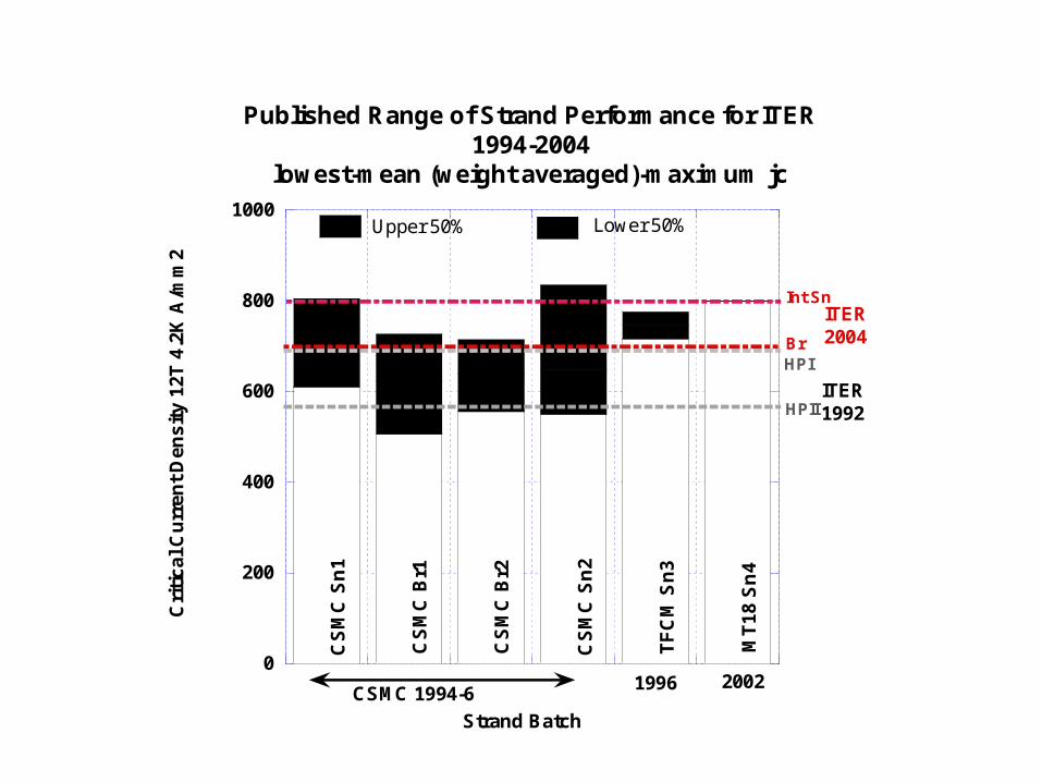
Published Range of Strand Performance for ITER1994-2004
lowest-mean (weight averaged)-maximum jcC
riti
cal
Cu
rren
t D
ens
ity
12T
4.2
K A
/mm
2
Strand Batch
ITER1992
ITER2004
Upper 50% Lower 50%
CSMC 1994-620021996
Br
HPII
Int Sn
HPI
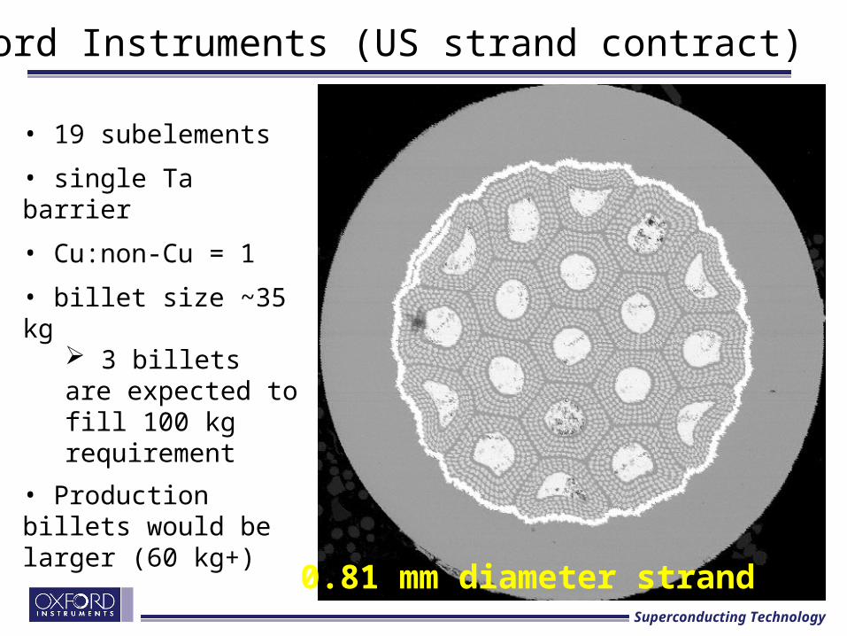
Oxford Instruments (US strand contract)
• 19 subelements
• single Ta barrier
• Cu:non-Cu = 1
• billet size ~35 kg 3 billets are expected to fill 100 kg requirement
• Production billets would be larger (60 kg+)
0.81 mm diameter strandSuperconducting Technology
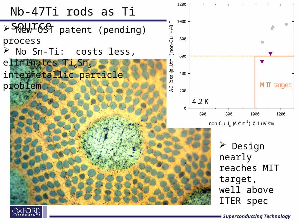
Nb-47Ti rods as Ti source New OST patent (pending) process No Sn-Ti: costs less, eliminates Ti6Sn5 intermetallic particle problem
non-Cu Jc (A/mm2) 0.1 uV/cm
600 800 1000 1200
AC
loss
(m
J/cm
3 ) no
n-C
u
+/-
3 T
0
200
400
600
800
1000
1200
4.2 K
MIT target
Design nearly reaches MIT target, well above ITER spec
Superconducting Technology
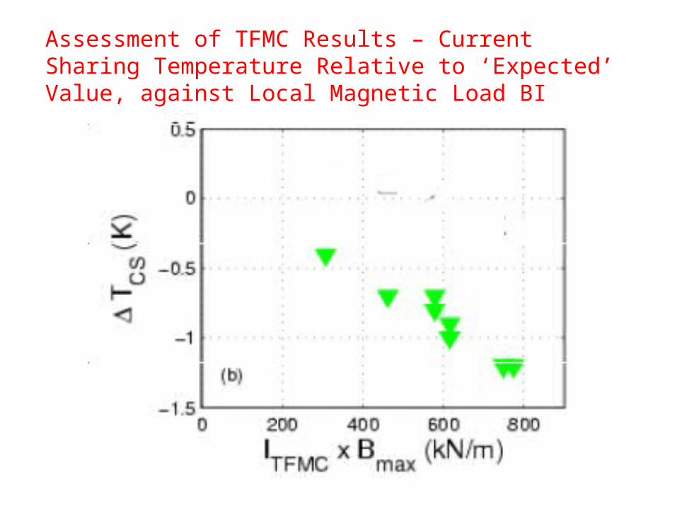
Assessment of TFMC Results – Current Sharing Temperature Relative to ‘Expected’ Value, against Local Magnetic Load BI
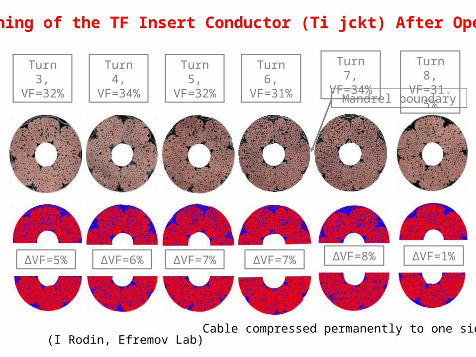
Turn 3, VF=32%
Turn 4, VF=34%
Turn 5, VF=32%
Turn 6, VF=31%
Turn 7, VF=34%
Turn 8, VF=31.5
%
∆VF=5% ∆VF=1%∆VF=6% ∆VF=7% ∆VF=7% ∆VF=8%
Mandrel boundary
Sectioning of the TF Insert Conductor (Ti jckt) After Operation
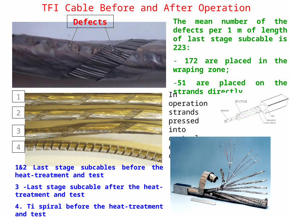
(I Rodin, Efremov Lab)Cable compressed permanently to one side
1
2
3
4
The mean number of the defects per 1 m of length of last stage subcable is 223:
- 172 are placed in the wraping zone;
-51 are placed on the strands directly
1&2 Last stage subcables before the heat-treatment and test
3 -Last stage subcable after the heat-treatment and test
4. Ti spiral before the heat-treatment and test
Defects
In operation strands pressed into central cooling channel
TFI Cable Before and After Operation
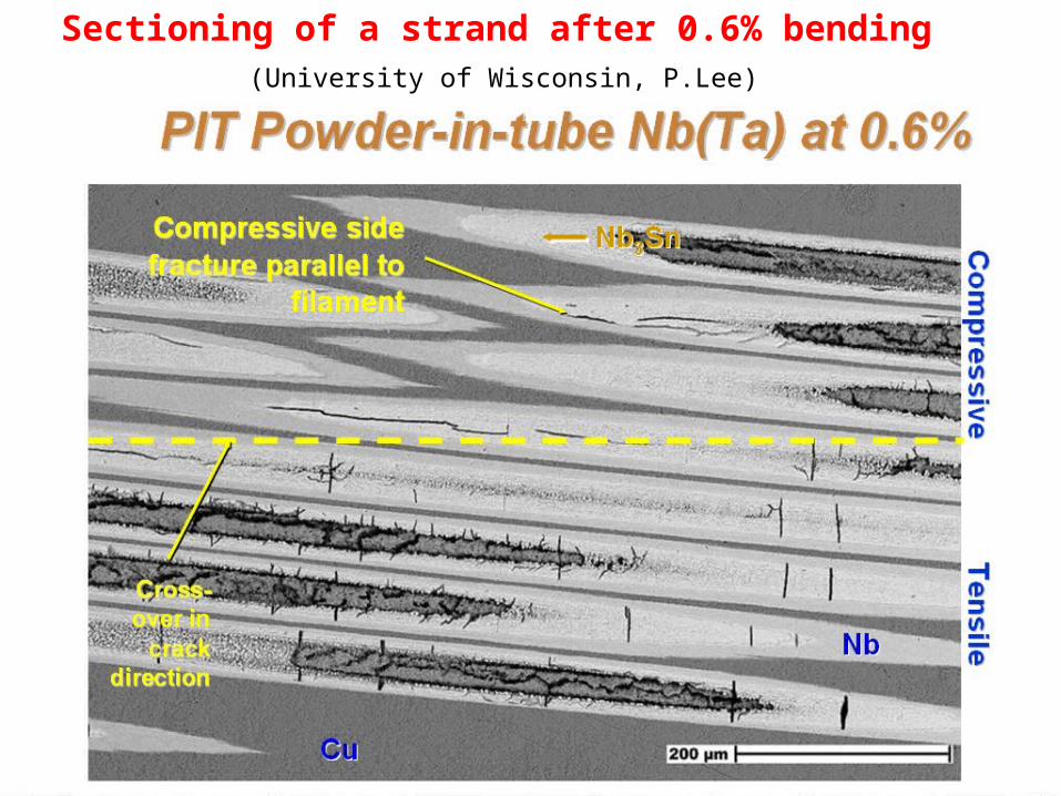
Sectioning of a strand after 0.6% bending(University of Wisconsin, P.Lee)
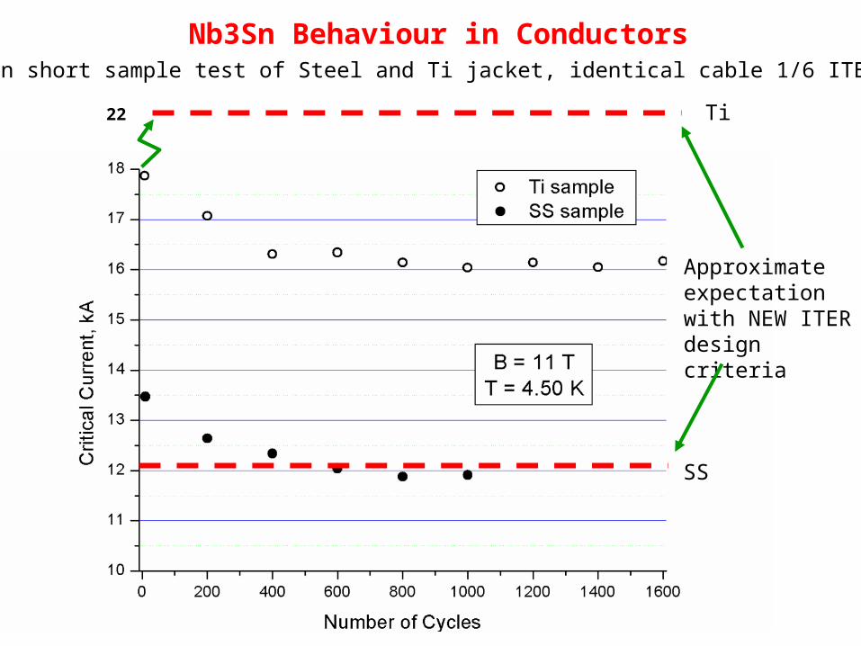
Nb3Sn Behaviour in ConductorsSultan short sample test of Steel and Ti jacket, identical cable 1/6 ITER scale
Approximate expectation with NEW ITER design criteria
22
SS
Ti
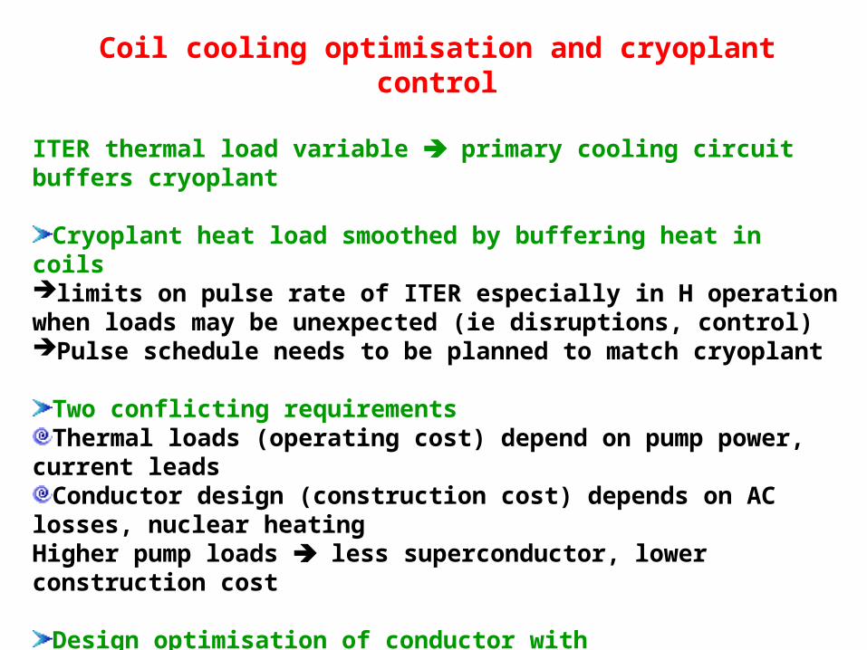
Coil cooling optimisation and cryoplant control
ITER thermal load variable primary cooling circuit buffers cryoplant
Cryoplant heat load smoothed by buffering heat in coilslimits on pulse rate of ITER especially in H operation when loads may be unexpected (ie disruptions, control)Pulse schedule needs to be planned to match cryoplant
Two conflicting requirementsThermal loads (operating cost) depend on pump power, current
leadsConductor design (construction cost) depends on AC losses,
nuclear heatingHigher pump loads less superconductor, lower construction cost
Design optimisation of conductor with Central cooling channel to reduce pressure drop (and pump power)Minimum length cooling channels compatible with windingOptimised He inlets (low pressure drop)
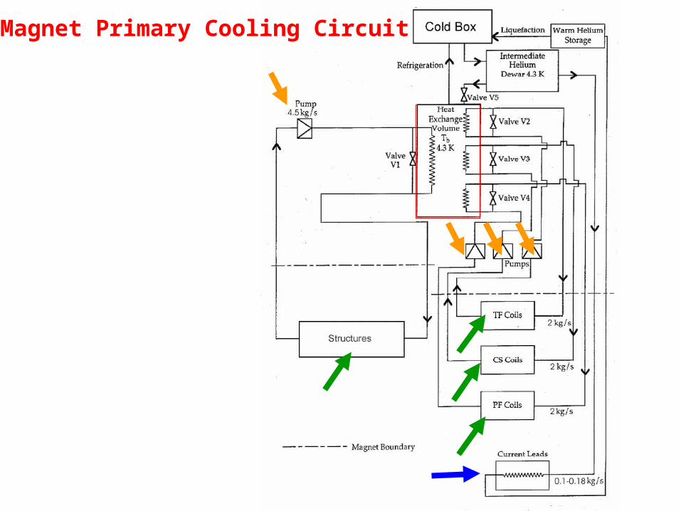
Magnet Primary Cooling Circuit
0
5000
1 104
1.5 104
2 104
Init
iati
on
an
d R
U 1
30s
Bu
rn 4
00s
Ra
mp
do
wn
37
0s
Dw
ell
590s
Pre
-ma
gn
eti
sati
on
310
s
AC losses and joints
Conduction and thermal radiation
Eddy Currents
Nuclear
Pumping
Current Leads
En
erg
y in
to C
ryo
gen
ic S
yste
m a
t 4K
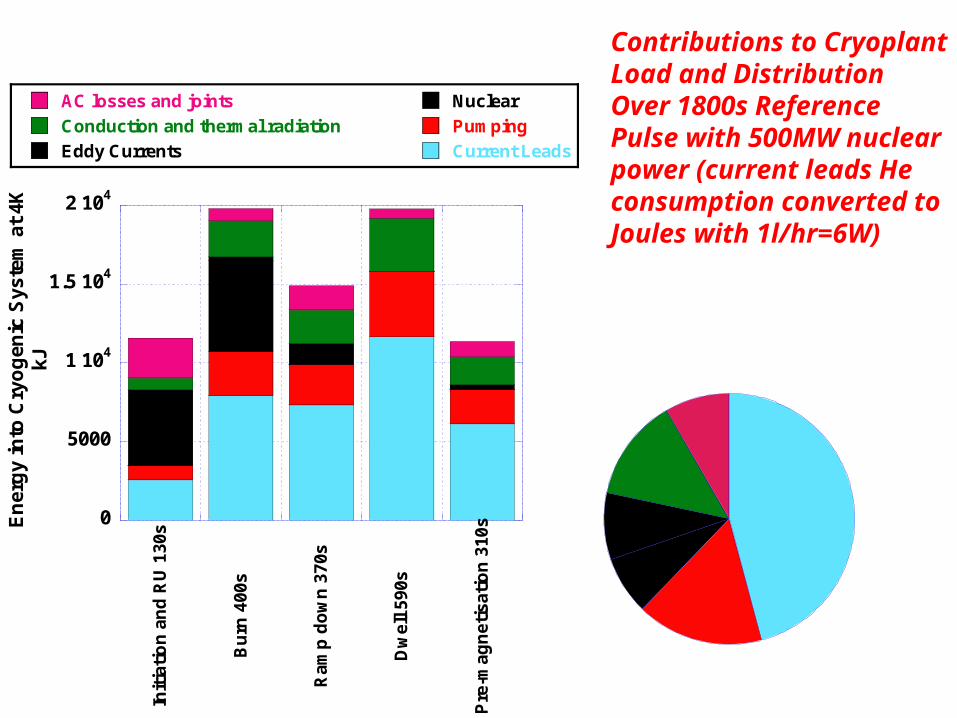
kJContributions to Cryoplant Load and Distribution Over 1800s Reference Pulse with 500MW nuclear power (current leads He consumption converted to Joules with 1l/hr=6W)
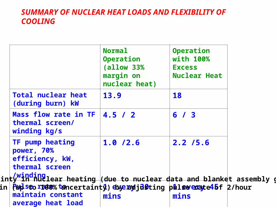
SUMMARY OF NUCLEAR HEAT LOADS AND FLEXIBILITY OF COOLING
Normal Operation (allow 33% margin on nuclear heat)
Operation with 100% Excess Nuclear Heat
Total nuclear heat (during burn) kW
13.9 18
Mass flow rate in TF thermal screen/ winding kg/s
4.5 / 2 6 / 3
TF pump heating power, 70% efficiency, kW, thermal screen /winding
1.0 /2.6 2.2 /5.6
Pulse rate to maintain constant average heat load
1 every 30 mins 1 every 45 mins
Uncertainty in nuclear heating (due to nuclear data and blanket assembly gaps) Margin (up to 100% uncertainty) by adjusting pulse rate of 2/hour
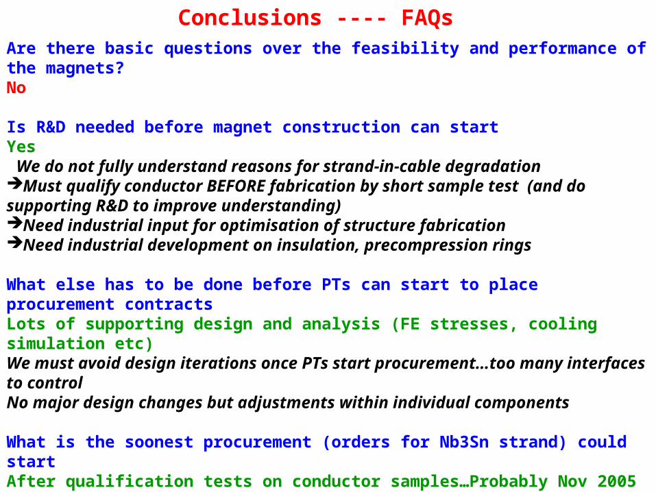
Conclusions ---- FAQsAre there basic questions over the feasibility and performance of the magnets?No
Is R&D needed before magnet construction can startYes We do not fully understand reasons for strand-in-cable degradationMust qualify conductor BEFORE fabrication by short sample test (and do supporting R&D to improve understanding)Need industrial input for optimisation of structure fabricationNeed industrial development on insulation, precompression rings
What else has to be done before PTs can start to place procurement contractsLots of supporting design and analysis (FE stresses, cooling simulation etc)We must avoid design iterations once PTs start procurement…too many interfaces to controlNo major design changes but adjustments within individual components
What is the soonest procurement (orders for Nb3Sn strand) could startAfter qualification tests on conductor samples…Probably Nov 2005
What is limiting progress on the magnet designEffort available to IT to work on main issues
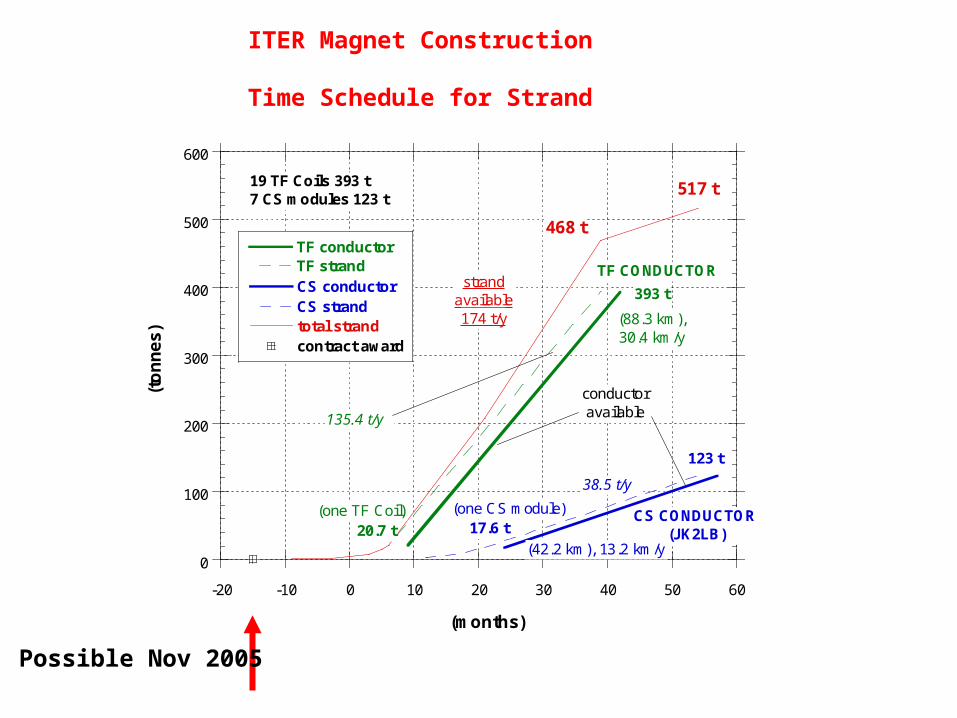
ITER Magnet Construction
Time Schedule for Strand
0
100
200
300
400
500
600
-20 -10 0 10 20 30 40 50 60
TF conductorTF strandCS conductorCS strandtotal strandcontract award
(to
nn
es)
(months)
CS CONDUCTOR(JK2LB)
123 t
17.6 t(one CS module)
38.5 t/y
(42.2 km), 13.2 km/y
393 t
TF CONDUCTOR
(88.3 km),30.4 km/y
(one TF Coil)20.7 t
135.4 t/y
517 t
468 t
strandavailable174 t/y
conductoravailable
19 TF Coils 393 t7 CS modules 123 t
Possible Nov 2005


![The Wisconsin Mycological Society NEWSLETTER...Mushrooms of Northeastern North America [Paperback] by Alan E. Bessette (Author), David W. Fischer (Author), Arleen Raines Bessette (Author)](https://img.pdfslide.us/doc/110x75/5f085f787e708231d421b004/the-wisconsin-mycological-society-newsletter-mushrooms-of-northeastern-north.jpg)