Embed Size (px)
Citation preview

DESIGN OF TEST RIG FOR BENDING AND TORSION OF VEHICLE STRUCTURE
MUHAMAD ARIF FAHMI BIN ABDUL WAHAB
UNIVERSITI TEKNIKAL MALAYSIA MELAKA

‘I/We* admit that I/we* have read this dissertation and in my/our* opinion this
dissertation is satisfactory in the aspect of scope and quality for the bestowal of
Bachelor of Mechanical Engineering (Automotive)
Signature : …………………………………….
Supervisor Name (I) : Mr. Ahmad Bin Rivai
Date : …………………………………….
Signature : …………………………………….
Supervisor Name (II) : Prof. Dr. Md. Radzai Bin Said
Date : …………………………………….

DESIGN OF TEST RIG FOR BENDING AND TORSION ON VEHICLE STRUCTURE
MUHAMAD ARIF FAHMI BIN ABDUL WAHAB
This report was submitted in accordance with the partial requirements for the honor of Bachelor of Mechanical Engineering (Automotive)
Faculty of Mechanical Engineering Universiti Teknikal Malaysia Melaka
APRIL 2009

ii
“I verify that this report is my own word except summary and extract that every one
of it I have clarify the resource”
Signature : ...............................................................
Author’s Name : Muhamad Arif Fahmi Bin Abdul Wahab
Date : 18 MAY 2009
iii
Dedicated
To my beloved Mum and Dad,
To my respectful Supervisor,
To my honorable Lecturers,
&
To my fellow Friends.

iv
ACKNOWLEDGEMENT The writer would like to say thanks to writer Supervisor, Mr. Ahmad Rivai
for his guidance and supports on writer during the Projek Sarjana Muda’s completion
period.
The co-operation given by the laboratory management especially the
technicians that involve in helping the completion of writer project are appreciated.
Acknowledgement is also dedicated to all people and personnel who whether
directly or indirectly involved in completing this project. Hope this report will be a
reference for other student in the future.

v
ABSTRACT Test Rig for bending and torsion on vehicle structure was used to measure the
deformation of the structure and measuring the loads produce on all tires during
bending and torsion case. In designing this test rig, the total loads from the vehicle
structure have been identified under bending and torsion case. The test rig function
to produce the torsion and bending case and the loads is measured by using the load
cell. The test rig is attached to the vehicle structure using a universal vehicle-test rig
attachment. Finite element method is used to validate the design whether it is strong
enough or not. If not, then the several researches will be done to repairing the
design.

vi
ABSTRAK
Rig ujian bagi kilasan dan lenturan terhadap struktur kenderaan in digunakan
atas tujuan untuk mengukur herotan yang terhasil pada struktur, dan juga untuk
mengukur daya yang bertindak pada kesemua tayar semasa keadaan lenturan dan
kilasan pada struktur kenderaan. Dalam merekabentuk rig ujian ini, keseluruhan
daya yang terhasil dari struktur kenderaan semasa kilasan dan lenturan perlulah
dikenalpasti. Rig ujian ini berfungsi dalam mewujudkan keadaan lenturan dan
kilasan selain daya yang bertindak semasa keadaan-keadaan tersebut diukur
menggunakan ‘load cell’. Rig ujian ini akan disambungkan pada struktur kenderaan
melalui penyambung universal struktur kenderaan-rig ujian. Setelah siap rekabentuk
terakhir bagi rig ujian ini, Kaedah Unsur Terhingga digunakan untuk memastikan
bahawa rig ujian ini selamat digunakan atau tidak. Jika rig ujian ini tidak selamat
digunakan, beberapa kajian tambahan akan dilakukan bagi memperbaiki rekabentuk
sedia ada.

vii
TABLE OF CONTENT
CHAPTER
TOPIC
CONFESSION
DEDICATION
ACKNOWLEDGEMENT
ABSTRACT
ABSTRAK
TABLE OF CONTENT
LIST OF TABLES
LIST OF FIGURES
LIST OF SYMBOLS
LIST OF APPENDICES
PAGE
ii
iii
iv
v
vi
vii
x
xi
xv
xvi
CHAPTER 1 INTRODUCTION
1.1 Background
1.2 Problem Statement
1.3 Objectives
1.4 Scope
1
1
2
2

viii
CHAPTER TOPIC
PAGE
CHAPTER 2 LITERATURE REVIEW
2.1 Background
2.2 Principle of Design and Stress
Analysis
2.2.1 Material
2.2.2 Stress
2.2.3 Design Factors
2.2.4 Buckling
2.2.5 Finite Element Method
2.3 Torsion & Bending on Vehicle
Structure
2.3.1 Bending Case
2.3.2 Torsion Case
2.4 Test Configuration
2.4.1 Static Bending Test
2.4.2 Static Torsion Test
2.5 Test Rig Design
2.5.1 Previous Design
2.5.2 Test Rig-Vehicle Attachment
3
3
4
4
6
7
10
12
12
14
15
17
17
19
19
22
CHAPTER 3
METHODOLOGY
3.1 Methodology Planning
3.2 Project Workflow
3.3 Design Specification
3.4 Design Selection
3.4.1 Test Rig Frame Structure
3.4.2 Test Rig Additional
Structure
3.4.3 Load Measurement Device
3.4.4 Test rig-Vehicle Attachment
3.5 Geometrical Dimension
24
25
26
27
27
29
32
34
38

ix
CHAPTER TOPIC
3.6 Material Selection
3.7 Strength Calculation
3.8 Finite Element Analysis
3.8.1 Individual Analysis
3.8.2 Test Rig Frame Analysis
PAGE
40
41
47
47
49
CHAPTER 4 RESULT & DISCUSSION
4.1 Final Design
4.2 Finite Element Analysis Result
51
58
CHAPTER 5 CONCLUSION & SUGGESTION
5.1 Background
5.2 Conclusion
5.3 Suggestion
67
67
68
REFERENCES
APPENDICES
70
72

x
LIST OF TABLES
NO.
TITLE PAGE
2.2.0
2.2.1
2.2.2
3.4.0
3.4.1
3.8.2
Guidelines on choosing design factor for
ductile material
(Source: Robert L. Mott (2004))
Guidelines on choosing design factor for
brittle material
(Source: Robert L. Mott (2004))
Values of K for effective length, Le = KL, for
different end connections
(Source: Robert L. Mott (2004))
Advantages and Disadvantages of each height
adjuster type
Data of vehicles dimensions and weights
Points coordinate for bar element of the test
rig
7
7
8
31
38
50

xi
LIST OF FIGURES
NO.
TITLE PAGE
2.2.0
2.2.1
2.3.0
2.3.1
2.3.2
2.4.0
2.4.1
2.4.2
2.5.0
2.5.1
2.5.2
Cutting element or pieces structure
(Source: Ahmad Rivai (2007))
Example of finite element on structure
(Source: Ahmad Rivai (2007))
Vehicle Bending Case
(Source: Robertson John (2002))
Typical passenger vehicle bending loads
(Source: Robertson John (2002))
Vehicle Torsion Case
(Source: Robertson John (2002))
Vehicle Structure with Bonded / Bolted Parts
(Source: Porsche Engineering Services, Inc.)
Vehicle Structure on Test Rig for Static Bending
(Source: Porsche Engineering Services, Inc.)
Vehicle Structure on Test Rig for Static Torsion
(Source: Porsche Engineering Services, Inc.)
Test Rig for Static Bending
(Source: Porsche Engineering Services, Inc.)
Test Rig for Static Torsion
(Source: Porsche Engineering Services, Inc.)
UTM 1998 test rig design without front & rear
body attachment column
(Source: Zakariah, A.M (1998))
10
11
12
13
14
15
17
19
20
20
21

xii
NO.
2.5.3
2.5.4(a)
2.5.4(b)
2.5.4(c)
3.2.0
3.4.0
3.4.1
3.4.2
3.4.3
3.4.4(a)
3.4.4(b)
3.4.4(c)
3.4.4(d)
3.4.5
3.4.6
3.4.7
3.4.8(a)
TITLE
Strut Mount Designs
(Source: Monroe Shocks & Struts (2008))
Inner Plate Design
(Source: Monroe Shocks & Struts (2008))
Centre Sleeve Design
(Source: Monroe Shocks & Struts (2008))
Spacer Bushing Design
(Source: Monroe Shocks & Struts (2008))
Project Workflow and Methodology
Front view of x-direction adjustable link
attachment between left side and right side for
front and rear frames
Isometric view of z-direction adjustable link
between front and rear frame with support
structure on all links
Example diagram of creating Bending case on
vehicle structure
Example diagram of creating Torsion case on
vehicle structure
Changeable column with various height
Fixed column with scissor jack
Fixed column with worm/helical gear jack
Fixed column with hydraulic jack
Total load direction to load measurement device
Position Load Measurement Device on the test rig
Example of Compression and tension Load cell;
Pancake-type and S-type
(Source: Puls Elektronik Sistemleri Ltd. (2008))
BMW 3 series E46 1998 same rear and front
suspension system as BMW 3 series E36 1997
(Source: Reimpell, J et al. (2001))
PAGE
23
23
23
23
25
28
28
29
30
30
30
31
31
33
33
34
35

xiii
NO.
3.4.8(b)
3.4.8(c)
3.4.9(a)
3.4.9(b)
4.1.0(a)
4.1.0(b)
4.1.0(c)
4.1.0(d)
4.1.0(e)
4.1.0(f)
4.1.0(g)
4.1.0(h)
4.1.1
4.2.0(a)
4.2.0(b)
4.2.0(c)
4.2.0(d)
4.2.0(e)
4.2.0(f)
4.2.0(g)
4.2.0(h)
4.2.0(i)
4.2.0(j)
4.2.0(k)
TITLE
Example of front axle Mc-Pherson strut for Lancia
Delta and BMW Roadster Z3)
(Source: Reimpell, J et al. (2001))
BMW 3series (1997) Multi link rear axle
suspension type
(Source: Reimpell, J et al. (2001))
Top view of rear body attachment and the position
of rear body attachment on test rig column
Side view of front vehicle-test rig attachment part
Front/Left frame
Front/Right frame
Rear/Right frame
Rear/Left frame
Front connector (ball joint base)
Rear Connector
Front/Left additional column
Test rig assembly
Load cell reference drawing
(Source: FUTEK Adv Sensor Tech. Inc. (2008))
FEA result for column (Stress Tensor)
FEA result for column (Displacement)
FEA result for column (Eigenvectors)
FEA result for front connector (Stress Tensor)
FEA result for front connector (Stress Tensor)
FEA result for front connector (Displacement)
FEA result for rear connector (Stress Tensor)
FEA result for rear connector (Displacement)
FEA result for test rig frame (Von Misses Axial)
FEA result for test rig frame (Displacement)
FEA result for test rig frame (Eigenvectors)
PAGE
35
36
36
37
53
53
54
54
55
55
56
56
57
58
59
59
60
60
61
62
62
63
64
64

xiv
NO.
4.2.0(l)
4.2.0(m)
4.2.0(n)
TITLE
FEA result for test rig frame – torsion load (Von
Mises Axial)
FEA result for test rig frame – torsion load
(Deformation)
FEA result for test rig frame – torsion load
(Eigenvectors)
PAGE
65
66
66

xv
LIST OF SYMBOLS
F
A
τmax
T
J
c
r
I
Le
K
Cc
E
N
σy
Pcr
Pa
P
Mzs
M zns
RF
RR
L
LF
LR
MB
σB
=
=
=
=
=
=
=
=
=
=
=
=
=
=
=
=
=
=
=
=
=
=
=
=
=
=
Force, kgm/s2 (N)
Area, m2
Shear stress, N/m2 (Pa)
Torque, Nm
Polar moment of inertia, m4
Radius of the shaft to its outside surface, mm
Radius of gyration, mm
Moment of inertia of the cross section, m4
Effective length, mm
Constant dependent on the end fixity
Column constant
Modulus of elasticity / Modulus young, N/m2 (Pa)
Safety factor
Yield strength, N/m2 (Pa)
Critical load, kgm/s2 (N)
Allowable load, kgm/s2 (N)
Actual applied load, kgm/s2 (N)
Dynamic load factor in bending
Dynamic load factor in torsion
Load on front axle, kgm/s2 (N)
Load on rear axle, kgm/s2 (N)
Wheelbase, mm
Distance from centre of gravity to front axle, mm
Distance from centre of gravity to rear axle, mm
Bending moment, Nm
Stress due to the bending, N/m2 (Pa)
xvi
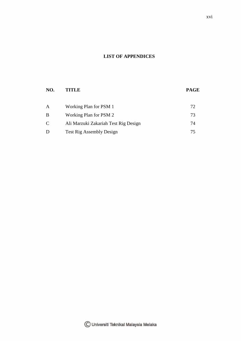
LIST OF APPENDICES
NO.
TITLE PAGE
A
B
C
D
Working Plan for PSM 1
Working Plan for PSM 2
Ali Marzuki Zakariah Test Rig Design
Test Rig Assembly Design
72
73
74
75

1
CHAPTER 1
INTRODUCTION
1.1 Background
Test Rig for bending and torsion on vehicle structure has been widely used by
automotive car manufacturers and researchers to measure the vehicle strength and
stiffness on a static bending and static torsion case of the vehicle structure. By using
that rig, an artificial situation of bending and torsion can be produced. Moreover, the
load and the stiffness of the vehicle can be measured for static bending and static
torsion condition. Most of researcher and automotive manufacturer will then
measure the stiffness of the vehicle structure on bending condition and torsion
condition. By then, based on the result, the car manufacture or the researchers will
estimate the vehicle stiffness and modification on the vehicle structure design will be
done if needed.
1.2 Problem Statement
In Universiti Teknikal Malaysia Melaka, the learning process for subject
Vehicle Structure Analysis on Torsion and Bending has been done theoretically. It is
because, currently, there is no such laboratory equipment to conduct a test for
bending and torsion on vehicle structure. So, in a short term period, there is a need
for student to design and develop such equipment to help faculty on providing the
laboratory equipment (specifically; test rig) to support laboratory use for testing the

2
bending and torsion on vehicle structure to increase the students (specifically;
Automotive’s student) understanding on that matter.
1.3 Objective
This thesis is done to design and analyze a test rig for measuring torsion and bending
on vehicle structure.
1.4 Scopes
- Understanding on principal of bending and torsion on vehicle structure
- Study of structural design and analysis
- Design of test rig; design selection, geometrical dimension, material
selection, strength calculation and solid modeling
- Strength analysis on test rig solid model using Finite Element Method
- Report writing and documentation

3
CHAPTER 2
LITERATURE REVIEW
2.1 Background
In designing the test rig for bending and torsion, it is needed to understand the
related principle of design and stress analysis. Moreover, the test configuration and
previous test rig design must be studied so that the suitable test rigs design, which
fulfills the criteria and requirement of the test configuration, can be created.
2.2 Principle of Design and Stress Analysis
In designing the test rig, the specifications of the test rig such as functions,
design requirements and evaluation criteria must be defined clearly. According
Mott (2004), functions tell what the device must do, using general, non-quantitative
statements that employ action phrases such as to support a load, to lift a crate, to
transmit power or to hold two structural members together. Moreover he said, design
requirements are detailed, usually quantitative statements of expected performance
levels, environmental conditions in which the device must operate limitations on
space or weight or available materials and components that may be used. Whereas,
evaluation criteria are the statements of desirable qualitative characteristics of a
design that assist the designer in deciding which alternative design is optimum- that
is, the design that maximizes benefits while minimizing disadvantages.

4
To start a design on the test rig, a lot of factors must be taken into
consideration. Mott (2004) has summarized some factors to be taken into
consideration, which as listed below:
- Forces exerted by the components of the machine through mounting points such
as bearings, pivots, brackets, and feet of other machine elements
- Manner of support of the frame itself
- Precision of the system: allowable deflection of components
- Environment in which the unit will operate
- Quantity of production and facilities available
- Availability of analytical tools such as computerized stress analysis, past-
experience with similar products, and experimental stress analysis
- Relationship to other machines, walls and so on
2.2.1 Material
Selection of material has a high effect on the structure strength. The most
significant factor to evaluate the material strength is by referring to the yield
strength, σy and the modulus of elasticity, E of the material. Mott (2004) stated that,
yield strength can be defined as the portion of the stress-strain diagram where there is
a large increase in strain with little or no increase in stress. He also stated that
modulus of elasticity can be define as stress proportionality to strain when the part of
the stress-strain diagram is straight. Modulus of elasticity indicates the stiffness of
the material or its resistance to deformation.
2.2.2 Stress
Based on Mott (2004), there are three basic fundamental kinds of stress;
tensile, compressive and shear. Tensile and compressive stress, called normal
stresses, are shown acting perpendicular to opposite faces of the stress element.
Tensile stresses tend to pull on the element whereas compressive stresses tend to

5
crush it. Shear stresses are created by direct shear, vertical shear in beams or torsion.
In each case, the action on an element subjected to shear is a tendency to cut the
element by exerting a stress downward on one face while simultaneously exerting a
stress upward on the opposite, parallel face. Stress can be defined as the internal
resistance offered by a unit area of a material to an externally applied load.
σ = force/area = F/A
When a torque or twisting moment is applied to a member, it tends to deform
by twisting, causing a rotation of one part of the member relative to another. Such
twisting causes a shear stress in the member. For a small element of the member, the
nature of the stress is the same as that experienced under direct shear stress.
However, in torsional shear, the distribution of stress is not uniform across the cross
section (Mott (2004)). When subjected to a torque, the outer surface of a solid round
shaft experiences the greatest sharing strain and therefore the largest torsional shear
stress. The value of maximum torsional shear stress is found from:
τmax = Tc/J
where; c = radius of the shaft to its outside surface
J = polar moment of inertia
T = Torque
Based on Mott (2004), the behavior of members having noncircular sections
when subjected to torsion is radically different from that for members having circular
cross sections. However, the factors of must use in machine design are the
maximum stress and the total angle of twist for such members. The formulas for
these factors can be expressed in similar forms to the formulas used for members of
circular section (solid and hollow round shafts).
Τmax = T/Q
where; Q = section modulus
Based on Mott (2004), a beam is a member that carries loads transverse to its
axis. Such loads produce bending moments in the beam, which result in the

6
development of bending stresses. Bending stresses are normal stresses, that is, either
tensile or compressive. The maximum bending stress in a beam cross section will
occur in the part farthest from the neutral axis of the section. At that point, the
flexure formula gives the stress:
σ =Mc/I
where; M = magnitude of the bending moment at the section
I = moment of inertia of the cross section with respect to its neutral axis
c = distance from the neutral axis to the outermost fiber of the beam cross
section
Positive bending occurs when the deflected shape of the beam is concave
upward, resulting in compression on the upper part of the cross section and tension
on the lower part. Conversely, negative bending causes the beam to be concave
downward.
When the dimension is already fixed, the yield strength of the material can be
change to make sure the design will not failed due to bending at specify force. So,
by using the dimension, calculate the moment of the beam. Then calculate the stress
due to the bending and compare it with yield strength of the material. If the stress
due to bending is smaller than yield strength of material, thus it mean that the beam
dimension with the material used will not failed if the specify force is applied.
2.2.3 Design Factors
Based on Mott (2004), design factor, N is a measure of the relative safety of
load-carrying component. He stated that in most cases, the strength of the material
from which the component is to be made is divided by the design factor to determine
a design stress, σd sometimes called the allowable stress. Then the actual stress to
which the component is subjected should be less than the design stress. For the case
of the buckling of columns, the design factor is applied to the load on the column
rather than the strength of the material.