Embed Size (px)
Citation preview
Design of TELESAR V
for Transferring Bodily Consciousness in Telexistence
Charith Lasantha Fernando1, Masahiro Furukawa1, Tadatoshi Kurogi1,
Sho Kamuro2, Katsunari Sato3, Kouta Minamizawa1 and Susumu Tachi1
Abstract— This paper focuses on design of a dexterousanthropomorphic robot where the operator can perceive thetransferring bodily consciousness to the slave robot during atele-operation. Accordingly, we propose a telexistence surrogateanthropomorphic robot called “TELESAR V”, which wasdesigned and constructed by development of the following:a 52 DOF slave robot with a torso, upper limbs, hands andhead to model the operator’s posture on all parts of the upperbody and maintain a 6 DOF accuracy in arm endpoint; a HDHead mounted display with 6 DOF point of view accuracyfor wide angle stereovision; and a mechanism for sensingand reproducing fingertip haptic and thermal sensation. Thispaper describes the development of the TELESAR V system,where the effectiveness has been verified through functionalexperiments.
I. INTRODUCTION
Telexistence is a concept that refers to the technology,
which enables a human to have a real-time sensation of being
at a place other than where he actually exist, and to interact
with the remote environment [1]. In 1988, an exoskeleton
type master-slave telexistence cockpit [2] called TELESAR
I was developed. In 2005, a mutual telexistence master-
slave system called TELESAR II [3] was developed with
human-like arm and hand movements. The system had the
functionality to perform conventional verbal communication
with a remote participant as well as nonverbal gestures
such as handshaking. In 2007, a TORSO with a head [4]
was developed with human-like neck movements to visually
interact and explore 3-dimensional details in a remote object
in a more natural and comfortable manner. With this system,
operator was able to feel a natural visual sensation in a tele-
operation due to the 6 DOF point of view accuracy (position
and orientation) of robot vision.
In general, humans experience the conscious self as local-
ized within their bodily borders. Due to high level of spatial
unity perceived with multi sensory inputs makes human to
think that the body they see, and can feel touch is their own
body. Also, researches have proved that if the same spatial
unity is kept with a high level of multi sensory applied
to a human, neurological conditions such as Rubber Hand
1C.L. Fernando, M. Furukawa, T. Kurogi, K. Minamizawa and S. Tachiis with Graduate School of Media Design, Keio University.
2S. Kamuro is with Graduate School of Information Science and Tech-nology, The University of Tokyo.
3K. Sato is with Graduate School of System Design and Management,Keio University. Address: 4-1-1 Hiyoshi, Kohoku-ku, Yokohama,JAPAN. 223-8526; Telephone:+81-45-564-2499; email: {charith,m.furukawa, kurogi, kamuro, sato, kouta,tachi}@tachilab.org
Illusion (RHI) [5] and Body Transfer Illusion [6], [7] can be
felt.
In telexistence, if the operator can feel the slave robot as
an expansion of his bodily consciousness, and also the ability
to freely move and control the slave robot in a similar way
to how his body moves, it will increase the throughput of
the performed remote task. In order to prove this concept in
telexistence, it is essential to have the following fundamental
requirements.
1) Operator should be able to freely and independently
move his head, upper body, arms and hands. In
contrast, slave robot’s hands should follow similar
movements while maintaining 6 DOF accuracy of arm
endpoint.
2) Operator should be able to clearly see a wide angle
stereo view of the remote site with 6 DOF point of
view accuracy of robot vision. In addition ability to
perform binaural, bi-directional verbal communication
is required.
3) Operator should be able to grasp and manipulate
objects in a similar way to a human hand.
4) Operator should feel fingertip haptic and thermal sen-
sation when touching objects remotely.
In order to address the above points, a master slave
robot system with higher level of dexterity is necessary. We
developed “TELESAR V”, a master slave robot system with
a conjunction of 52 DOF to perform full body movements.
In addition operator can feel the fingertip haptic and thermal
sensation when touching objects remotely.
II. DESIGN CONSIDERATIONS OF TELESAR V
Conventional tele-operation system sometimes uses ex-
oskeleton based master system [2] to capture the movements
of operator. These systems limits the operator’s movements
to the exoskeleton system’s mechanical constrains. Thus in
order to satisfy the first condition, a non-mechanical, not
direct attachable measurement system is necessary. This
also gives full flexibility to move head, body and arms
independently as desired.
In order to map the point of view and arm endpoint 6 DOF,
a higher DOF robot is necessary. Conventional dexterous
robots [8] are not capable of achieving this due to not
having enough DOF in the torso part. A robot that can
mimic similar spinal movements (extension, flexion, lateral
flexion, and axial rotation) similar to a human is required as
robot’s torso. In order to address this point, both torso and
2012 IEEE/RSJ International Conference onIntelligent Robots and SystemsOctober 7-12, 2012. Vilamoura, Algarve, Portugal
978-1-4673-1736-8/12/S31.00 ©2012 IEEE 5112
an anthropomorphic robot arm with minimum of 6 DOF is
required.
Installing wide-angle full HD cameras on slave robot and
a wide angle HD Head Mounted Display (HMD) as the
operator vision, the second condition can be satisfied. In
conventional robots, [2], [9] in case of requiring a spinal
movement, robots performs a locomotive operation using
it’s mobile platform and navigate towards/away/sides while
operator controls the movement using a joystick or similar
technology. Since the operator does not move his upper body,
it is difficult to maintain a 6 DOF point of view accuracy of
robot vision. Thus a 3 DOF head is necessary. Furthermore
torso, head, arm and hand should be in a single kinematic
chain to obtain the accuracy of each component. Installing
microphones as robot’s ears and speaker as robot’s mouth
and similar configuration on HMD will provide bi-directional
verbal communication capabilities.
To satisfy the third conditions a higher DOF anthropo-
morphic robot hand similar to human hand is required.
Also fingertip force and temperature can be measured using
vision based force sensor and reproduced using vertical and
shearing forces on fingertip. Thus forth condition can be
satisfied.
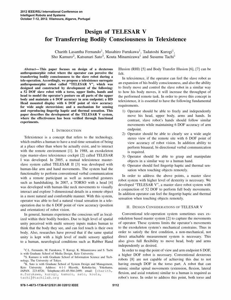
Fig. 1. (a) Master-Slave configurtion, (b) HD wide angle view, (c) Slaverobot
We developed a telexistence master-slave system called
“TELESAR V” that satisfies the above mentioned four
conditions. As shown in Fig. 1(a) operator can freely move
in his space while able to mimic the spinal movements and
perform human-like body assisted stroke motion. As shown
in Fig. 1(b) robot can maintain a 6 DOF point of view and
arm endpoint accuracy so that the vector between the two
points of vision and arm endpoint is seamlessly mapped
to the operators same points. By adding fingertip haptic
sensation [10] into the master slave robot system it concludes
that TELESAR V can satisfy the above four conditions.
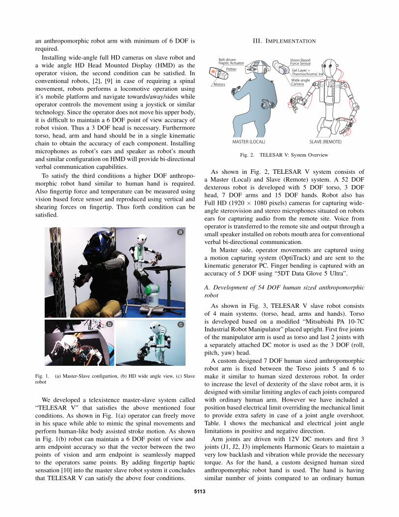
III. IMPLEMENTATION
Belt driven Haptic Actuator
Peltier
Motors
MASTER (LOCAL)
Vision Based Force Sensor
Wide-angle Camera
Gel Layer + Thermochromic Ink
SLAVE (REMOTE)
Fig. 2. TELESAR V: System Overview
As shown in Fig. 2, TELESAR V system consists of
a Master (Local) and Slave (Remote) system. A 52 DOF
dexterous robot is developed with 5 DOF torso, 3 DOF
head, 7 DOF arms and 15 DOF hands. Robot also has
Full HD (1920 × 1080 pixels) cameras for capturing wide-
angle stereovision and stereo microphones situated on robots
ears for capturing audio from the remote site. Voice from
operator is transferred to the remote site and output through a
small speaker installed on robots mouth area for conventional
verbal bi-directional communication.
In Master side, operator movements are captured using
a motion capturing system (OptiTrack) and are sent to the
kinematic generator PC. Finger bending is captured with an
accuracy of 5 DOF using “5DT Data Glove 5 Ultra”.
A. Development of 54 DOF human sized anthropomorphic
robot
As shown in Fig. 3, TELESAR V slave robot consists
of 4 main systems. (torso, head, arms and hands). Torso
is developed based on a modified “Mitsubishi PA 10-7C
Industrial Robot Manipulator” placed upright. First five joints
of the manipulator arm is used as torso and last 2 joints with
a separately attached DC motor is used as the 3 DOF (roll,
pitch, yaw) head.
A custom designed 7 DOF human sized anthropomorphic
robot arm is fixed between the Torso joints 5 and 6 to
make it similar to human sized dexterous robot. In order
to increase the level of dexterity of the slave robot arm, it is
designed with similar limiting angles of each joints compared
with ordinary human arm. However we have included a
position based electrical limit overriding the mechanical limit
to provide extra safety in case of a joint angle overshoot.
Table. I shows the mechanical and electrical joint angle
limitations in positive and negative direction.
Arm joints are driven with 12V DC motors and first 3
joints (J1, J2, J3) implements Harmonic Gears to maintain a
very low backlash and vibration while provide the necessary
torque. As for the hand, a custom designed human sized
anthropomorphic robot hand is used. The hand is having
similar number of joints compared to an ordinary human
5113

Overall Weight : 500g
(Excluding Force and
Temperature Sensors)
TELESAR V HAND
TELESAR V BODY and HEAD
TELESAR V ARM
Neck Pitch,Yaw
Neck Roll(±30°)
Overall Body Weight:50kg
All dimensions are in millimeters (mm)
24
0
15
65
28
02
00
31
54
50
50
0
30
10
0
380
11
0
65
280 240 200
300
33
0
50
11
24
YH
XH3
3.5
16 2
0
2
20
20
92
01
0.5
XH
66
22
42
30
25
185
18
78
1025304515
I
V
IV
II
III
11.5
ZH
14.5
Fig. 3. Kinematic Configuration of Head, Body, Arm and Hand
hand. Robot fingers are driven by 15 individual DC motors
and a dynamically coupled wires and a pulley driven mech-
anism couples the remaining joints that does not directly
attach to a motor. (Note: Mechanical components of Arm,
Hand and Head are developed in KAWABUCHI Mechanical
Engineering Laboratory, Inc.)
TABLE I
JOINT LIMITS OF 7 DOF ANTHROPOMORPHIC ROBOT ARM
JointMechanical Angle limit Electrical Angle Limit
Negative Positive Negative Positive
J1 (Shoulder) -90◦ 145◦ -90◦ +145◦
J2 (Shoulder) -100◦ +20◦ -100◦ +18◦
J3 (upper arm) -152◦ +32◦ -150◦ +30◦
J4 (elbow) -135◦ -2◦ -130◦ 0◦
J5 (lower arm) -93◦ +93◦ -90◦ +90◦
J6 (wrist) -15◦ +45◦ -15◦ +40◦
J7 (wrist) -45◦ +60◦ -40◦ +60◦
All the DC motors are connected to standard DC motor
drivers with a combination of optical encoders and po-
tentiometer reading as position measurement. Furthermore
voltage and current consumption is monitored at each motor
and torque at motor shaft is calculated. Communication
between the motor drivers and PC is carried out through
a PCI-Express x1 bus.
B. Development of the wide angle HD sterovision system
In order to capture Full HD video from the robot, a CMOS
camera head (Model no: TOSHIBA IK-HK1H) and a wide
angle lens (Model no: FUJINON TF4DA-8) configuration
as the robot’s eye were used. Two camera’s were installed
parallel to each other having a distance of 65mm.
To provide a HD wide-angle stereovision sensation to
the operator, a HD (1280 × 800 pixels) wide-angle Head
Mounted Display was developed (Fig. 4). In order to provide
the wide angle and maintain a small footprint, we have
used 5.6"(inch) LCD display (Model no: HV056WX1-100)
and increased the length of optical flow using a special
lens arrangement. HMD has two parallel virtual projection
planes located 1m far away from two eye balls, to obtain
stereoscopic vision independently between the eyes, thus
operator can feel correct distance [11]. A knob is provided
at the front side of HMD so that the operator can adjust
the convergence angle of left and right eye for a clear
stereovision. At the output stage of the HMD, a video flipper
(Model no: XC1 Sio) for each eye is used to correct the
vertical flip due to the lens configuration.
65
94
205
φ45
139
Camera
LCD
Mirror
Lens
Fig. 4. TELESAR V: HMD Assembly view
With the above specifications, we were able to produce a
wide angle of H×V (61×40)◦(degrees) for each eye where
as the original captured video field of view was H×V
(62×48)◦(degrees). In addition, two cameras were installed
on the front side of HMD. This is useful when the operator
needs to turn his vision into a video see-through mode. A
complete spefication of the stereovision system is listed as
shown in the Table. II
C. Development of thermal and haptic transfer system
Robot’s fingers are installed with a vision-based cutaneous
sensor [12] to sense both force vector and temperature of fin-
gertip. As shown in Fig. 5(a) a CCD camera is continuously
tracking green and red markers placed on a transparent elastic
body. A white LED attached to the fingertip illuminates the
markers. In addition, another layer of thermo sensitive ink
is wafered in between elastic body and outer surface. The
outer surface is fabricated with black color elastic material,
which has similar tactile sensation characteristics to a human
finger when touched. (Fig. 5(b))
Remote fingertip proprioceptive sensation is reproduced
using vertical and shearing forces generated by motor driven
belt mechanism [13]. As shown in Fig. 6, a rotation in
opposite direction generates vertical stress while a rotation in
5114
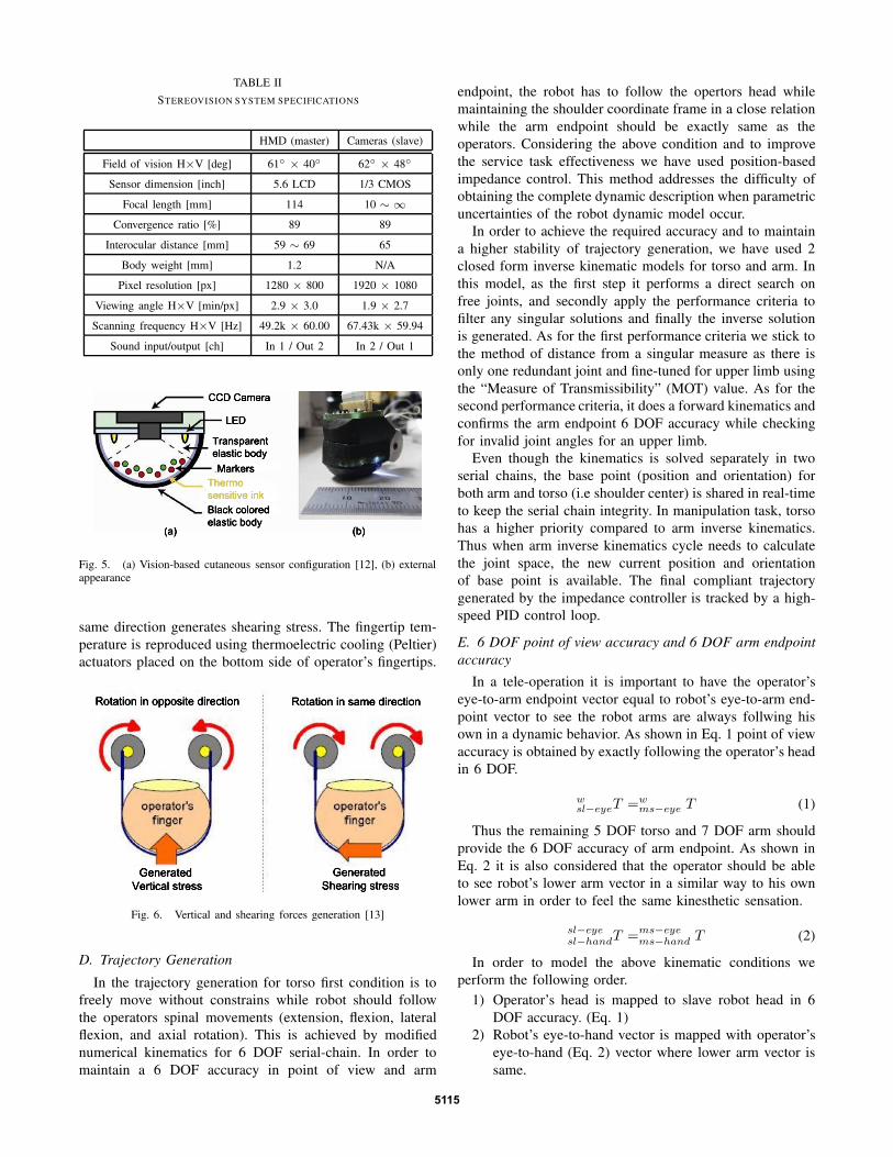
TABLE II
STEREOVISION SYSTEM SPECIFICATIONS
HMD (master) Cameras (slave)
Field of vision H×V [deg] 61◦ × 40◦ 62◦ × 48◦
Sensor dimension [inch] 5.6 LCD 1/3 CMOS
Focal length [mm] 114 10 ∼ ∞
Convergence ratio [%] 89 89
Interocular distance [mm] 59 ∼ 69 65
Body weight [mm] 1.2 N/A
Pixel resolution [px] 1280 × 800 1920 × 1080
Viewing angle H×V [min/px] 2.9 × 3.0 1.9 × 2.7
Scanning frequency H×V [Hz] 49.2k × 60.00 67.43k × 59.94
Sound input/output [ch] In 1 / Out 2 In 2 / Out 1
Fig. 5. (a) Vision-based cutaneous sensor configuration [12], (b) externalappearance
same direction generates shearing stress. The fingertip tem-
perature is reproduced using thermoelectric cooling (Peltier)
actuators placed on the bottom side of operator’s fingertips.
Fig. 6. Vertical and shearing forces generation [13]
D. Trajectory Generation
In the trajectory generation for torso first condition is to
freely move without constrains while robot should follow
the operators spinal movements (extension, flexion, lateral
flexion, and axial rotation). This is achieved by modified
numerical kinematics for 6 DOF serial-chain. In order to
maintain a 6 DOF accuracy in point of view and arm
endpoint, the robot has to follow the opertors head while
maintaining the shoulder coordinate frame in a close relation
while the arm endpoint should be exactly same as the
operators. Considering the above condition and to improve
the service task effectiveness we have used position-based
impedance control. This method addresses the difficulty of
obtaining the complete dynamic description when parametric
uncertainties of the robot dynamic model occur.
In order to achieve the required accuracy and to maintain
a higher stability of trajectory generation, we have used 2
closed form inverse kinematic models for torso and arm. In
this model, as the first step it performs a direct search on
free joints, and secondly apply the performance criteria to
filter any singular solutions and finally the inverse solution
is generated. As for the first performance criteria we stick to
the method of distance from a singular measure as there is
only one redundant joint and fine-tuned for upper limb using
the “Measure of Transmissibility” (MOT) value. As for the
second performance criteria, it does a forward kinematics and
confirms the arm endpoint 6 DOF accuracy while checking
for invalid joint angles for an upper limb.
Even though the kinematics is solved separately in two
serial chains, the base point (position and orientation) for
both arm and torso (i.e shoulder center) is shared in real-time
to keep the serial chain integrity. In manipulation task, torso
has a higher priority compared to arm inverse kinematics.
Thus when arm inverse kinematics cycle needs to calculate
the joint space, the new current position and orientation
of base point is available. The final compliant trajectory
generated by the impedance controller is tracked by a high-
speed PID control loop.
E. 6 DOF point of view accuracy and 6 DOF arm endpoint
accuracy
In a tele-operation it is important to have the operator’s
eye-to-arm endpoint vector equal to robot’s eye-to-arm end-
point vector to see the robot arms are always follwing his
own in a dynamic behavior. As shown in Eq. 1 point of view
accuracy is obtained by exactly following the operator’s head
in 6 DOF.
wsl−eyeT =w
ms−eye T (1)
Thus the remaining 5 DOF torso and 7 DOF arm should
provide the 6 DOF accuracy of arm endpoint. As shown in
Eq. 2 it is also considered that the operator should be able
to see robot’s lower arm vector in a similar way to his own
lower arm in order to feel the same kinesthetic sensation.
sl−eyesl−handT =ms−eye
ms−hand T (2)
In order to model the above kinematic conditions we
perform the following order.
1) Operator’s head is mapped to slave robot head in 6
DOF accuracy. (Eq. 1)
2) Robot’s eye-to-hand vector is mapped with operator’s
eye-to-hand (Eq. 2) vector where lower arm vector is
same.
5115

3) The error is compensated using the remaining DOF of
upper arm and torso.
It is also known that the human anatomy, wrist joint is
mostly restricted to movements of less than 180◦ (degrees).
Like most of the slave robots, in TELESAR V, wrist is
restricted with 60 ∼ 105 ◦(degrees) respectively due to
mechanical restrictions. The above model can overcome
this mechanical limitation because of the remaining DOF
compensation model.
(a) Without Body Movements (b) With Body Movements
Field Of
View
ROBOT Body
Remote Object
ROBOT Body
Remote Object
Field Of
View
Fig. 7. Orientation accuracy obtained through upper body compansation
In the method explained above while compensating, it is
important to nearly match the master torso and slave torso
posture. If the posture is different, due to the mechanical
limitations of joints, the level of dexterity will reduce and
resulting a very narrow space constrain to the operator. We
solve this issue by measuring the shoulder rotation (roll,
pitch, yaw) of master and model a close possible upper body
match. This method was really effective when the operator
tries to rotate his spine clockwise and counter clockwise. As
shown in Fig. 7(a), operator tries to reach the remote object
through correct orientation, but due to the joint limitation
of the wrist it is not possible. This kind of a situation is
naturally resolved by humans by use of spine to rotate the
body and approach using the extended right hand. As shown
in Fig. 7(b), such situation can be naturally resolved. With
this setup, we have achieved a high level of dexterity and
less complexity in object manipulation.
sl−shsl−handT =sl−eye
sl−sh T−1.ms−eyems−handT (3)
After the torso and head joint space is decided, as shown
in Eq. 3 the shoulder-to-hand vector is calculated in real-time
and perform numerical kinematics for 7 DOF serial-chain for
obtaining the arm joint space.
F. Communication Protocol and performance
Calculated joint space, robot’s fingertip force, fingertip
temperature, joint encoder, joint force data are arranged in
a special protocol and sent via UDP Multicast at a speed
of 1KHz. The data cycle speed is limited just to preserve
the bandwidth when doing real-time operations, but there is
no design limitations to increase this speed. These Multicast
data is received Hardware Clients who drives the torso and
arm/hands and also a seperate client who runs the TELESAR
V Simulator environment. The system is implemented with a
point-to-point network configuration so that the Master and
Slave can be physically located at different places in the
world.
However the HD Video link is currenty transmitted locally
to the Master side because to minimize the latency. We have
been testing the video link with network streaming, but only
up to VGA resolution (640 × 480 pixels) was successful in
reproducing the 3D vision with a minimum latecy which was
sufficient for telexistence operations.
IV. ACHIEVEMENTS OF TELESAR V
A 6 DOF point of view accuracy, 6 DOF arm endpoint
accuracy, ability to use the spinal movement and feel haptic
and thermal sensation, we found that TELESAR V can
perform many new interactions.
A. Body compensated hand movements with fixed head ori-
entation
Field Of
View
ROBOT Body
Remote
Object
(a) Without Body Movements (b) With Body Rotation
Field Of
View
ROBOT Body
Remote
Object
Fig. 8. Extend the reachability using body Axial rotation
As shown in Fig. 8(a), conventionally when the operator
is not able to reach a remote object by fully stretching the
arm, he needs to move the robot base close enough to reach
in its fully extended arm. But TELESAR V can rotate it’s
body with an axial rotation as shown in Fig. 8(b) and extends
the reach easily. This eliminates the use of moving the robot
base and preserves the human natural body movements. In
addition operator can see the remote object clearly and does
not need to change his head orientation while making axial
rotation.
B. Body compensated hand movements with dynamic head
orientation
Sometimes operator needs to explore the grabbed objects
carefully before or after picking it up. (For example picking
up a chemical container and reading the label). In a similar
situation, humans will naturally use a combination of head
5116

Field Of
View
ROBOT Body
Remote
Object
(a) Without Body Movements (b) With Body Transformation + Head Rotation
Field Of View
ROBOT Body
Remote
Object
Fig. 9. Expanding field of view through combined body and handmovements
and arm movements to rotate and explore the entire 360-
degree rotation. As shown in Fig. 9, a similar scenario can
be executed with TELESAR V by first grabbing the object
and keeping hand posture fixed and move the body and head
around to see around the object. Since the operator does not
move his hand position and orientation in world coordinates
slave robot preserves the arm endpoint.
C. Active compliant force
When manipulating objects humans usually use their body
as a support structure for arms and legs. (i.e back muscle
supports the arm movements.) It helps to generate impulse
forces when necessary. Similarly as shown in Fig. 10, with
TELESAR V the operator can induce an accelerated force at
the end point by a combined movement of body and arms.
This is not possible if the combined forces have a delay or
if the body and arm has different posture from the operator.
Fresultant = Fbody × cos(θ) + Farm (4)
As can be seen in Eq. 4 the tangential force component
created by the body rotation adds to the arm trajectory and
accelerates the end point movement. These accelerations help
to generate stroke and impulse motions.
Field Of View
ROBOT Body
Remote
Object
(a) Arm Force Only (b) Arm Force + Body Tangential force
Field Of View
ROBOT Body
Remote
Object
Resultant force = F(arm) Resultant force
= F(arm) + F(body) × cos (θ )
ROBOT Body
F(body)
θ
Fig. 10. Accelerated force during combined body and arm motion
This type of accelerated motion is also useful to perform
remote tasks faster compared to when using just arm motion.
V. FUNCTIONAL EXPERIMENTS OF TELESAR V
With all the above enhancements enabled we have per-
formed few functional tests to explore how the visual,
auditory, haptic and kinesthetic sensation enriches in a telex-
istence operation.
A. Remote glass ball pouring and stacking bricks
As shown in Fig. 11(a), operator grabs 2 cups placed on
the table and pours the glass balls from one to another. In
this experiment the placement of the cups on the table did
not matter because operator can see the cups and he can
extend his upper body and arms to reach the object. Due to
the accuracy of the system operator was confident enough
to perform a over-the-air ball pouring by holding 2 cups in
a vertical distance of around 15cm. In addition, due to the
haptic transfer system, operator can feel the tactile feedback
when glass balls hit the cup.
We have performed a similar test where there are 3 cubes
placed (Fig. 11(b)) on the table and ask the operator to
stack one over each. Operator could easily perform the task.
Secondly, one block was visually blocked but placed in a
reachable position. Operator first tried to reach the visually
blocked object by approaching through sides and saw a little
portion of the block. Having able to perceive the kinesthetic
sensation and have a sense of the robot arms position he was
able to grab it without any mistake.
Fig. 11. (a) Ball pouring, (b) stacking up bricks vertically
B. Writing Japanese Calligraphy using a brush and ink
In this experiment operator was given a brush, ink tank
and a piece of paper to write Japanese calligraphy. In
general, writing characters using a brush and ink requires
some practice, as the applied force has to be maintained
at a constant level above the paper surface. As shown in
Fig. 12(a), operator was able to pick up the brush from
holder, dip into the ink tank gently and write Japanese
calligraphy. During the writing operator was using his left
hand as a support so that the paper does not move due
to the stroke. In this experiment operator was using active
compliant force when he was writing an narrow brush stroke
where the ink trail has to be gradually modify from thick to
very narrow. The extended reach was used when he wanted
to dip the brush into the tank. Fig. 12(b) shows the completed
calligraphy.
5117

Fig. 12. (a) Japanese Calligraphy, (b) Completed Calligraphy
C. Manipulating small objects in densed environment
In this experiement, operator was given a Japanese Chess
board (Shogi) where he has to participate in a chess
game with a remote participant. The board dimensions
were 313mm×280mm×13mm (L×W×H) while the largest
wedge-shaped piece being 30mm×26mm×5mm and small-
est wedge-shaped pieces being 20mm×16mm×5mm. As
shown in Fig. 13(a), operator was able to pick and place
shogi pieces up to middle size. The second experiment as
shown in Fig. 13(b), operator was given a pile of sticks
diameter ranging from φ4mm to φ8mm. In this experiment,
operator was able to use fingertip haptic sensation to not
to apply over pressure to sticks. If the pressure is applied
without any control the stick will simply flip around.
Fig. 13. (a) playing Japanese chess (shogi), (b) picking thin sticks
VI. CONCLUSION
We proposed a dexterous anthropomorphic master slave
robot system where the operator can extend his bodily border
to the slave robot during a tele-operation.
In order satisfy the above condition, we designed and con-
structed a 52 DOF telexistence surrogate anthropomorphic
robot called “TELESAR V” where we were able to map the
vector between master’s point of view and arm endpoint to
the same vector of the slave robots’. In addition the operator
can feel auditory, visual, haptic and kinesthetic sensation
through the sensory and actuator arrangement. With the
higher level of multi sensory input and the accuracy of the
above mentioned criteria the operator was able to perform
basic tasks with confidence and no prior prctise. Even though
the system is not currently evaluated under a psychophysical
experiment, participants who tried the system felt their body
consciousness is extended up to the robot during a tele-
operation. Furthermore through out the experiments that we
have carried out, we prove that this technology is helpful for
carrying out tele-operations with confidence and experience
the real extended body consciousness.
ACKNOWLEDGEMENT
This project is supported by JST-CREST Haptic Media
Project and collaborated with Kyokko Electric co.,Ltd.
REFERENCES
[1] S. Tachi, Telexistence. World Scientific, 2010. [Online]. Available:http://www.worldscibooks.com/compsci/7079.html
[2] S. Tachi, H. Arai, and T. Maeda, “Tele-existence master-slave systemfor remote manipulation,” in Proceedings. IROS ’90. IEEE Interna-
tional Workshop on, jul 1990, pp. 343 –348 vol.1.[3] N. Kawakami and D. Sekiguchi, “TelesarPHONE - Communication
Robot based on Next Generation Telexistence Technologies -,” inInternational Symposium on Robotics, 2005, pp. 1–4.
[4] K. Watanabe, I. Kawabuchi, N. Kawakami, T. Maeda, andS. Tachi, “Torso: completion of egocentric telegnosis system,” inACM SIGGRAPH 2007 emerging technologies, ser. SIGGRAPH’07. New York, NY, USA: ACM, 2007. [Online]. Available:http://doi.acm.org/10.1145/1278280.1278302
[5] M. Botvinick and J. Cohen, “Rubber hands feel touch that eyessee.” Nature, vol. 391, no. 6669, p. 756, 1998. [Online]. Available:http://www.ncbi.nlm.nih.gov/pubmed/9486643
[6] M. Slater, B. Spanlang, M. V. Sanchez-Vives, and O. Blanke, “Firstperson experience of body transfer in virtual reality,” PLoS ONE,vol. 5, no. 5, p. e10564, 05 2010.
[7] B. Lenggenhager, T. Tadi, T. Metzinger, and O. Blanke, “Videoergo sum: manipulating bodily self-consciousness.” Science, vol.317, no. 5841, pp. 1096–1099, 2007. [Online]. Available:http://www.ncbi.nlm.nih.gov/pubmed/17717189
[8] B. Bauml, F. Schmidt, T. Wimbock, O. Birbach, A. Dietrich, M. Fuchs,W. Friedl, U. Frese, C. Borst, M. Grebenstein, O. Eiberger, andG. Hirzinger, “Catching flying balls and preparing coffee: Humanoidrollin’justin performs dynamic and sensitive tasks,” in Robotics and
Automation (ICRA), 2011 IEEE International Conference on, may2011, pp. 3443–3444.
[9] S. Tachi, K. Watanabe, K. Takeshita, K. Minamizawa, T. Yoshida, andK. Sato, “Mutual telexistence surrogate system: Telesar4 - telexistencein real environments using autostereoscopic immersive display -,” inIntelligent Robots and Systems (IROS), 2011 IEEE/RSJ International
Conference on, sept. 2011, pp. 157 –162.[10] K. Sato, K. Minamizawa, N. Kawakami, and S. Tachi, “Haptic
telexistence,” in ACM SIGGRAPH 2007 emerging technologies, ser.SIGGRAPH ’07. New York, NY, USA: ACM, 2007. [Online].Available: http://doi.acm.org/10.1145/1278280.1278291
[11] S. Tachi, K. Tanie, K. Komoriya, and M. Kaneko, “Tele-existence (i):Design and evaluation of a visual display with sensation of presence,”in Proceedings. 5th International Symposium on Theory and Practice
of robots and Manipulators on, june 1984, pp. 245 –254 vol.1.[12] K. Sato, K. Kamiyama, N. Kawakami, and S. Tachi, “Finger-shaped
gelforce: Sensor for measuring surface traction fields for robotic hand,”IEEE Transactions on Haptics, vol. 3, pp. 37–47, 2010.
[13] K. Minamizawa, S. Kamuro, S. Fukamachi, N. Kawakami, andS. Tachi, “Ghostglove: haptic existence of the virtual world,” inACM SIGGRAPH 2008 new tech demos, ser. SIGGRAPH ’08. NewYork, NY, USA: ACM, 2008, pp. 18:1–18:1. [Online]. Available:http://doi.acm.org/10.1145/1401615.1401633
5118