Embed Size (px)
Citation preview
Design of Storage and Handling Facility for Petroleum Productsby Eng. Eshak Ibrahim Zaki
Supervised by Dr. Mohsen S. Soliman, ACCManager, Mech.Power Eng.Dept.
MEP 599 Diploma Design Project-Term1 2017/2018
Abstract: This an exercise for design of storage & handling facility for 3 different
petroleum products. Tanks are used to store incoming products for later domestic
demand such as in small service stations. A total Facility area is assumed about
6000m2(123x48m). Assumed layout of this facility has inlet unloading station (from
railways/ships), 3 vertical tanks, internal pipe-lines, required pumping &truck
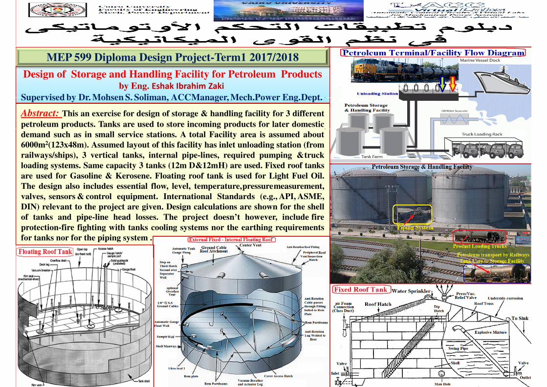
loading systems. Same capacity 3 tanks (12m D&12mH) are used. Fixed roof tanks
are used for Gasoline & Kerosene. Floating roof tank is used for Light Fuel Oil.
The design also includes essential flow, level, temperature,pressuremeasurement,
valves, sensors & control equipment. International Standards (e.g., API, ASME,
DIN) relevant to the project are given. Design calculations are shown for the shell
of tanks and pipe-line head losses. The project doesn’t however, include fire
protection-fire fighting with tanks cooling systems nor the earthing requirements
for tanks nor for the piping system .
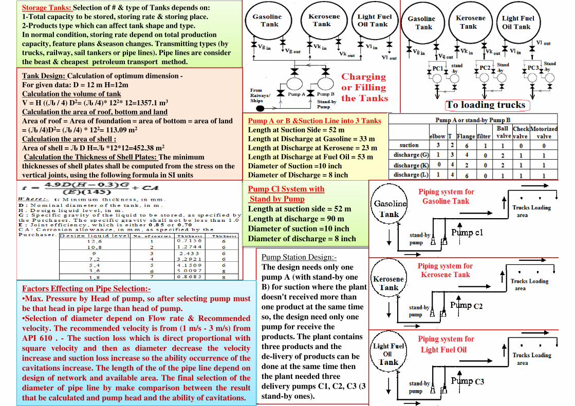
Storage Tanks: Selection of # & type of Tanks depends on:
1-Total capacity to be stored, storing rate & storing place.
2-Products type which can affect tank shape and type.
In normal condition, storing rate depend on total production
capacity, feature plans &season changes. Transmitting types (by
trucks, railway, sail tankers or pipe lines). Pipe lines are consider
the beast & cheapest petroleum transport method.
Tank Design: Calculation of optimum dimension -
For given data: D = 12 m H=12m
Calculation the volume of tank
V = H ((Ԉ / 4) D2= (Ԉ /4)* 122* 12=1357.1 m3
Calculation the area of roof, bottom and land
Area of roof = Area of foundation = area of bottom = area of land
= (Ԉ /4)D2= (Ԉ /4) * 122= 113.09 m2
Calculation the area of shell :
Pump A or B &Suction Line into 3 Tanks
Length at Suction Side = 52 m
Length at Discharge at Gasoline = 33 m
Pump Station Design:-
The design needs only one
Calculation the area of shell :
Area of shell = Ԉ D H=Ԉ *12*12=452.38 m2
Calculation the Thickness of Shell Plates: The minimum
thicknesses of shell plates shall be computed from the stress on the
vertical joints, using the following formula in SI units
Length at Discharge at Gasoline = 33 m
Length at Discharge at Kerosene = 23 m
Length at Discharge at Fuel Oil = 53 m
Diameter of Suction =10 inch
Diameter of Discharge = 8 inch
Pump Cl System with
Stand by Pump
Length at suction side = 52 m
Length at discharge = 90 m
Diameter of suction =10 inch
Diameter of discharge = 8 inch
The design needs only one
pump A (with stand-by one
B) for suction where the plant
doesn't received more than
one product at the same time
so, the design need only one
pump for receive the
products. The plant contains
three products and the
de-livery of products can be
done at the same time then
the plant needed three
delivery pumps C1, C2, C3 (3
stand-by ones).
Factors Effecting on Pipe Selection:-
•Max. Pressure by Head of pump, so after selecting pump must
be that head in pipe large than head of pump.
•Selection of diameter depend on Flow rate & Recommended
velocity. The recommended velocity is from (1 m/s - 3 m/s) from
API 610 . - The suction loss which is direct proportional with
square velocity and then as diameter decrease the velocity
increase and suction loss increase so the ability occurrence of the
cavitations increase. The length of the of the pipe line depend on
design of network and available area. The final selection of the
diameter of pipe line by make comparison between the result
that be calculated and pump head and the ability of cavitations.
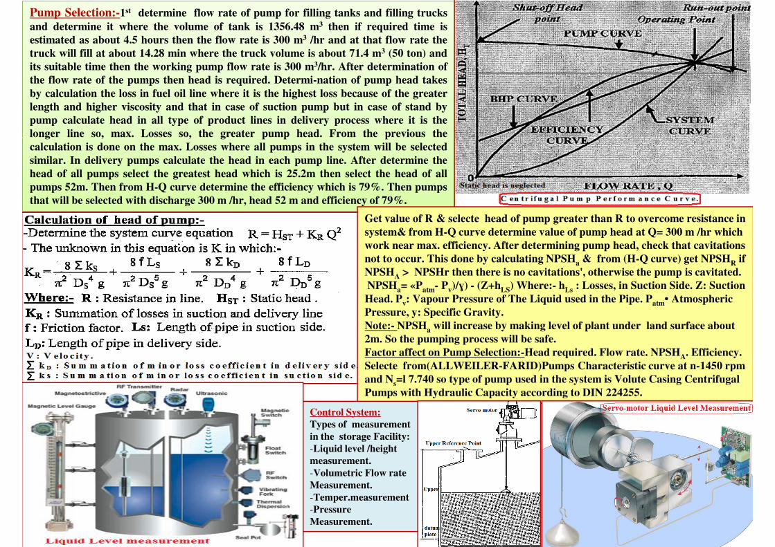
Pump Selection:-1st determine flow rate of pump for filling tanks and filling trucks
and determine it where the volume of tank is 1356.48 m3 then if required time is
estimated as about 4.5 hours then the flow rate is 300 m3 /hr and at that flow rate the
truck will fill at about 14.28 min where the truck volume is about 71.4 m3 (50 ton) and
its suitable time then the working pump flow rate is 300 m3/hr. After determination of
the flow rate of the pumps then head is required. Determi-nation of pump head takes
by calculation the loss in fuel oil line where it is the highest loss because of the greater
length and higher viscosity and that in case of suction pump but in case of stand by
pump calculate head in all type of product lines in delivery process where it is the
longer line so, max. Losses so, the greater pump head. From the previous the
calculation is done on the max. Losses where all pumps in the system will be selected
similar. In delivery pumps calculate the head in each pump line. After determine the
head of all pumps select the greatest head which is 25.2m then select the head of all
pumps 52m. Then from H-Q curve determine the efficiency which is 79%. Then pumpspumps 52m. Then from H-Q curve determine the efficiency which is 79%. Then pumps
that will be selected with discharge 300 m /hr, head 52 m and efficiency of 79%.
Get value of R & selecte head of pump greater than R to overcome resistance in
system& from H-Q curve determine value of pump head at Q= 300 m /hr which
work near max. efficiency. After determining pump head, check that cavitations
not to occur. This done by calculating NPSHa & from (H-Q curve) get NPSHR if
NPSHA > NPSHr then there is no cavitations', otherwise the pump is cavitated.
NPSHa= «Patm- Pv)/ɣ) - (Z+hLS) Where:- hLs : Losses, in Suction Side. Z: Suction
Head. Pv: Vapour Pressure of The Liquid used in the Pipe. Patm• Atmospheric
Pressure, y: Specific Gravity.
Note:- NPSHa will increase by making level of plant under land surface about
2m. So the pumping process will be safe.
Factor affect on Pump Selection:-Head required. Flow rate. NPSHA. Efficiency.
Selecte from(ALLWEILER-FARID)Pumps Characteristic curve at n-1450 rpm Selecte from(ALLWEILER-FARID)Pumps Characteristic curve at n-1450 rpm
and Ns=l 7.740 so type of pump used in the system is Volute Casing Centrifugal
Pumps with Hydraulic Capacity according to DIN 224255.
Control System:
Types of measurement
in the storage Facility:
-Liquid level /height
measurement.
-Volumetric Flow rate
Measurement.
-Temper.measurement
-Pressure
Measurement.
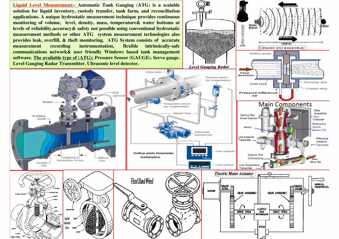
Liquid Level Measurement:- Automatic Tank Gauging (ATG) is a scalable
solution for liquid inventory, custody transfer, tank farm, and reconciliation
applications. A unique hydrostatic measurement technique provides continuous
monitoring of volume, level, density, mass, temperature& water bottoms at
levels of reliability,accuracy& safety not possible using conventional hydrostatic
measurement methods or other ATG system measurement technologies also
provides leak, overfill, & theft monitoring. ATG System consists of accurate
measurement recording instrumentation, flexible intrinsically-safe
communications network& user friendly Windows based tank management
software. The available type of (ATG): Pressure Sensor (GAUGE). Servo gauge.
Level Gauging Radar Transmitter. Ultrasonic level detector.