Embed Size (px)
Citation preview
Chaos, Solitons and Fractals 24 (2005) 241–255
www.elsevier.com/locate/chaos
Design of secure digital communication systems usingchaotic modulation, cryptography and chaotic synchronization
Tsun-I Chien a,b, Teh-Lu Liao a,*
a Department of Engineering Science, National Cheng Kung University, Tainan, 701, Taiwan, Republic of Chinab Department of Electronics Engineering, Kao Yuan Institute of Technology, Kaohsiung County 821, Taiwan, Republic of China
Accepted 14 September 2004
Communicated by Prof. M. Wadati
Abstract
This paper presents a secure digital communication system based on chaotic modulation, cryptography, and chaotic
synchronization techniques. The proposed system consists of a Chaotic Modulator (CM), a Chaotic Secure Transmitter
(CST), a Chaotic Secure Receiver (CSR) and a Chaotic Demodulator (CDM). The CM module incorporates a chaotic
system and a novel Chaotic Differential Peaks Keying (CDPK) modulation scheme to generate analog patterns corre-
sponding to the input digital bits. The CST and CSR modules are designed such that a single scalar signal is transmitted
in the public channel. Furthermore, by giving certain structural conditions of a particular class of chaotic system, the
CST and the nonlinear observer-based CSR with an appropriate observer gain are constructed to synchronize with each
other. These two slave systems are driven simultaneously by the transmitted signal and are designed to synchronize and
generate appropriate cryptography keys for encryption and decryption purposes. In the CDM module, a nonlinear
observer is designed to estimate the chaotic modulating system in the CM. A demodulation mechanism is then applied
to decode the transmitted input digital bits. The effectiveness of the proposed scheme is demonstrated through the
numerical simulation of an illustrative communication system. Synchronization between the chaotic circuits of the
transmitter and receiver modules is guaranteed through the Lyapunov stability theorem. Finally, the security features
of the proposed system in the event of attack by an intruder in either the time domain or the frequency domain are
discussed.
� 2004 Elsevier Ltd. All rights reserved.
1. Introduction
Since the pioneering work of Carroll and Pecora [1] in the field of chaos control in 1991, digital communication tech-
niques based on chaotic systems have been the subject of intensive study. A literature review reveals a large number of
related studies, including chaotic coding [2–9], chaotic modulation/demodulation [10–14], and multiple-access commu-
nications [15–21]. In conventional digital communication systems, the data to be transmitted must first be mapped into
a weighted sum of analog sample functions (e.g. sine and cosine) and then transmitted in the public channel via RF
0960-0779/$ - see front matter � 2004 Elsevier Ltd. All rights reserved.
doi:10.1016/j.chaos.2004.09.009
* Corresponding author.
E-mail address: [email protected] (T.-L. Liao).
242 T.-I Chien, T.-L. Liao / Chaos, Solitons and Fractals 24 (2005) 241–255
carriers. It is noted that these sample functions yield signals which are both periodic and narrowband in nature. Com-
pared to their wideband counterparts, narrowband communication systems generally involve significant signal attenu-
ation in multi-path propagation.
Two schemes have been developed to shift narrowband communications to a wideband configuration. In the first
scheme, known as direct sequence (DS) spread spectrum (SS) communications, a pseudorandom sequence is utilized
to spread the transmitted signal. In such a scheme, the effectiveness of multiple accesses is ensured by assigning these
sequences such that they are orthogonal to each other. It is noted that this scheme lies at the core of Code Division
Multiple Access (CDMA) communication systems. However, when the number of users accessing the communication
system is very large, maintaining the synchronization of these sequences throughout the entire system becomes prob-
lematic. It is known that chaotic signals are random-like, deterministic and wideband. In chaotic communication sys-
tems, replacing the sample functions (sine and cosine) with appropriate chaotic signals permits the advantage of
wideband communications in multi-path propagation systems to be realized. Various studies have successfully applied
chaotic signals to multiple access communications since the correlation between two chaotic signals is generally low [15–
21].
The second method proposed for shifting narrowband communications to a wideband configuration involves the use
of certain pieces of the chaotic signals to represent the digital data which is to be transmitted [10–14]. The Chaos Shift
Keying (CSK) and Differential Chaos Shift Keying (DCSK) modulation schemes are two well-known examples of this
particular approach. When using a coherent receiver, achieving chaotic synchronization [21–23] between the transmitter
and the receiver is a fundamental issue. The preliminary configuration of a chaotic synchronization scheme consists of a
drive chaotic system and a driven chaotic system, which are coupled unidirectionally [1]. Various studies have demon-
strated the pivotal role of chaos synchronization in secure communications [24–28]. Chaotic signal masking [24], com-
munication by signal reconstruction [25], communications-based active–passive decomposition [26], digital
communication by chaotic switching [27], and digital communication based on in-phase and anti-phase synchronization
[28] are particular examples in the field of chaotic communications. However, the results of [29,30] indicated that neither
the additive masking method nor the chaotic switching methods were very secure. Since a low-dimensional chaotic
attractor has a comparatively simple geometric structure, its description in terms of various measures is possible,
and hence an intruder may well be able to acquire the hidden text [37].
Two basic approaches have been proposed to enhance the safety of chaotic communication systems. In the first,
hyperchaotic systems are utilized for the transmitter and receiver modules, while in the second, a cryptosystem is com-
bined with the chaotic systems to treat the confidential message prior to its transmission. Hyperchaotic systems are
characterized by multiple positive Lyapunov exponents and have the merit of increased randomness and unpredictabil-
ity [31]. In such systems, the attractor�s structure is less readily described, and hence intruders are presented with a more
difficult task when attempting to attack the communication system. Several studies have proposed methods for the syn-
chronization of hyperchaotic systems by means of a transmitted signal [31–33]. A traditional cryptosystem comprises an
encrypter, an encryption algorithm, a decrypter, and a decryption algorithm. At the transmitting end, the encrypter mod-
ule applies an encryption algorithm to the plaintext message which is to be transmitted. The encryption algorithm can
be regarded as a mathematical transformation and generates so-called ciphertext. At the receiving end, this ciphertext is
decrypted by a decrypter module using a decryption algorithm, which essentially applies an inverse transformation,
thereby recovering the plaintext. Since the late 1970s, several cryptosystems have been proposed for public-key cryp-
tography [34,35]. It is possible to apply the encryption and decryption algorithms in the system for creating secure links,
and hence the security of the cryptosystem is dependent on maintaining the confidentiality of the associated keys. Gen-
erally speaking, establishing cryptosystems with chaotic systems is comparatively straightforward. The confidential keys
generated from the chaotic signals of such systems can be considered as random-like signals. Provided that the keys are
used only once and are not shorter than the message length, this form of cryptosystem can be considered to be reason-
ably secure [26].
Recently, various novel communication schemes combining both conventional cryptographic methods and the syn-
chronization of chaotic systems have been developed [26,36,37] to enhance the level of security. A common feature of
these systems is the utilization of the state variables of the chaotic systems (other than the transmitted state) as keys in
the encryption and decryption algorithms. Examples of these systems include the application of a low-dimensional
Chua�s circuit as a chaotic system in [36] and the use of an active–passive decomposition approach by He et al. in
[26]. In these systems, an independent low-dimensional chaotic system sends a driving signal to two chaotic slave sys-
tems, which are then synchronized and used to generate confidential keys. However, these systems have the drawback
that two signals must be sent, namely the driving signal for chaotic synchronization purposes, and the ciphertext which
is to be transmitted in the public channel. Using a nonlinear observer design, a more flexible and general approach to
secure communication has been proposed in [37]. In this system, the plaintext can only be retrieved if the correct struc-
tural properties of the chaotic system are satisfied. The adoption of hyperchaotic systems with their inherently more
T.-I Chien, T.-L. Liao / Chaos, Solitons and Fractals 24 (2005) 241–255 243
complex transmitted signals enhances the effectiveness of the communication scheme. However, one drawback in such
schemes is that all of the state variables of the incorporated chaotic systems must be noise-free and available for
measurement.
In light of the above developments, this study proposes a secure digital communication system utilizing chaotic mod-
ulation, cryptographic and chaotic synchronization techniques. This paper is organized as follows. Section 2 introduces
the proposed chaotic digital communication system, while Section 3 describes the design of the chaotic modulator em-
ployed to generate the analog patterns associated with the input digital bits. Subsequently, Section 4 describes the devel-
oped Chaotic Secure Transmitter (CST) and Chaotic Secure Receiver (CSR) modules and presents the two slave
systems which are driven simultaneously by the transmitted signal to generate cryptographic keys. Section 5 presents
the design of the chaotic demodulator used to recover the transmitted digital bits, while Section 6 verifies the proposed
communication system via numerical simulations of an illustrative communication system based on the Rossler-like sys-
tem and Chua�s circuits. Section 7 discusses the enhanced security features of the proposed system, and finally, Section 8
presents some brief conclusions and describes the direction for future research.
2. Proposed digital communication system
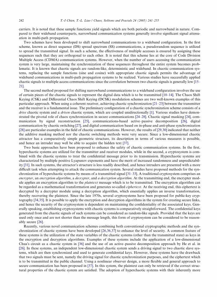
Fig. 1 presents a block diagram of the proposed communication system. It can be seen that the system comprises
four modules, namely the Chaotic Modulator (CM), the Chaotic Secure Transmitter (CST), the Chaotic Secure Recei-
ver (CSR), and the Chaotic Demodulator (CDM). In the CM, an off-line self-learning process is executed prior to the
transmitting period. In this learning process, a novel modulation scheme is applied to establish analog chaotic patterns
corresponding to the input bit sets. Subsequently, certain parameters of these chaotic patterns (i.e. the initial peak val-
ues) are digitized and stored in the modulator�s memory. In the transmitting period, a D/A converter is utilized to re-
trieve the digitalized parameters corresponding to the input bits from the modulator�s memory. These parameters are
then used to perturb the chaotic circuit (Rossler-like system) such that analog chaotic patterns, as opposed to the orig-
inal input bits, are transmitted to the CST. The CST and CSR modules are designed in such a way that a single scalar
signal is transmitted across the public channel. By giving certain structural conditions of a particular class of chaotic
system (Chua�s circuits), the main transmitter and the nonlinear observer-based main receiver with an appropriate ob-
server gain are constructed to synchronize with each other. These two slave systems are driven simultaneously by the
transmitted signal and are designed to synchronize and to generate confidential keys. Synchronization between the cha-
otic circuits in the CST and CSR modules is guaranteed through the Lyapunov stability theorem. The output of the
CSR is supplied to the CDM. The chaotic circuit of this module has the same system parameters as those of the
CM, but does not insist on the same initial states as those in the latter since the demodulator and the modulator
can be synchronized after a short transient period by using the proposed nonlinear observer-based synchronization
scheme. In the CDM, a bit detector measures the output of the CDM�s chaotic circuit and matches it with the corre-
sponding bit set, thereby recovering the transmitted input bits.
Maintransmitter
Encryptionalgorithm
Slavesystem 2
+
Chaotic securereceiver
Mainreceiver
Slavesystem 4
Decryptionalgorithm
+
Chaoticpatterns
Off-linelearning
Patternsoutput
Publicchannel
Chaoticdemodulator
Bit detector
ChaoticModulator
InputBits
)(ts
)(1 ty
)('1 ty
)(tK)(tp
Chaotic securetransmitter
y
)(ˆ tK
)(ˆ tp
y
)(ˆ1 ty
)('1 ty
Chaoticcircuit
Chaoticcircuit
)(ˆ ts
Received
Bits
Fig. 1. The block diagram of the proposed communication scheme.
244 T.-I Chien, T.-L. Liao / Chaos, Solitons and Fractals 24 (2005) 241–255
3. Design of Chaotic Modulator (CM)
The mapping of every two input bits into an analog symbol prior to transmission across the public channel is gen-
erally performed using either the QAM or QPSK modulation scheme. In the present study, every eight information bits
plus two synchronization bits are mapped into appropriate analog chaotic patterns in accordance with the results of the
self-learning process described previously in Section 2. In the self-learning process, the time evolution of one state var-
iable can be selected as the source for obtaining the chaotic patterns and can be observed from the free running chaotic
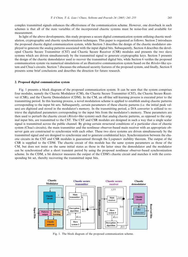
circuit in the CM. The local peak values of the selected state are recorded, and bits of either �0� or �1� are subsequentlyassigned to them in accordance with a specified encoding scheme. In the present study, if it is detected that the following
positive/negative peak value is greater than the current positive/negative peak value, this condition is marked as bit �1�,otherwise it is marked as bit �0�. Fig. 2 illustrates the proposed encoding method, in which P1, P2, P3, and P4 are the
positive peak values of state x3, while N1 and N2 are the negative peak values of state x3. Alternatively, if the intention
is to consider the effects of channel noise, the condition P2–P1 > a > 0 can be encoded as bit �1� and P2–P1 < b < 0 en-
coded as bit �0�, where a and b are noise threshold parameters. A similar operation can also be performed when encod-
ing the negative peak values. The characteristics of the proposed chaotic modulation scheme lend this scheme its name
of Chaotic Differential Peaks Keying (CDPK). The detailed procedures of the CDPK (off-line self-learning) can be sum-
marized as follows:
1. Enable the self-learning process.
2. Sample data from all states of the free running chaotic circuit in the CM.
3. Digitize these sampled data and detect local peak values of the selected output state and store these values in the
buffer.
4. In accordance with the encoding rule described in Fig. 2, match each N + 1 consecutive peak value with the appro-
priate N � s bit binary code from the buffer.
5. Store the first peak value of the consecutive series obtained in Step 4 and the digitized values of the other sampled
states at this moment in the CM�s memory.
6. Repeat from Steps 2 and 5 until all 2N�s binary codes have been found.
7. Disable the self-learning process and commence data transmission.
In Step 4, N and s denote the bit number of the transmitted symbol with synchronization bits and the bit number of
synchronization, respectively. During data transmission, the input bits are supplied to the proposed communication
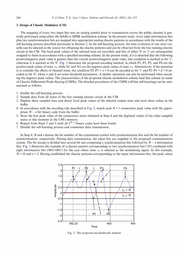
system. The bit stream is divided into several bit sets comprising s synchronization bits followed by N � s information
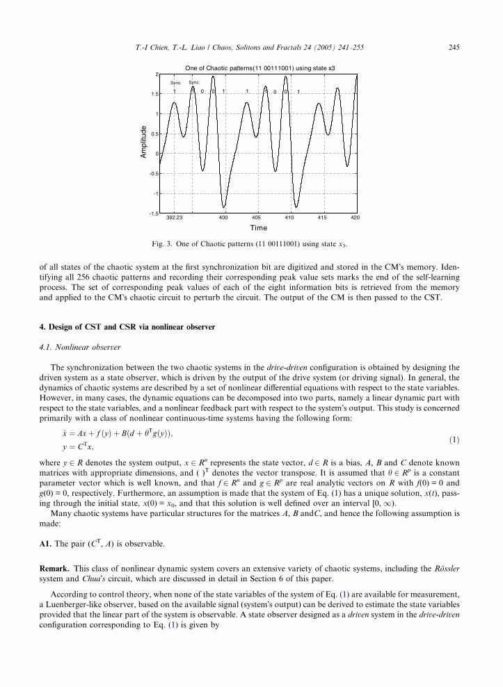
bits. Fig. 3 illustrates the example of a chaotic pattern corresponding to two synchronization bits (�10�) combined with
eight information bits (�00111001�) for the case where state x3 is selected as the modulating signal. In this example,
N = 10 and s = 2. Having established the chaotic patterns corresponding to the input information bits, the peak values
392.23 400 405-2.5
-2
-1.5
-1
-0.5
0
0.5
1
1.5
2
2.5
Time
Amplitude
P1 P2
1 01 0
03x
03x
P3< < P4
>
>
N1 N2>
Fig. 2. The proposed encode/decode method.
392.23 400 405 410 415 420 -1.5
-1
-0.5
0
0.5
1
1.5
2One of Chaotic patterns(11 00111001) using state x3
Time
Am
plitu
de
0111 0
Sync. Sync.
1 1 0 0 1
Fig. 3. One of Chaotic patterns (11 00111001) using state x3.
T.-I Chien, T.-L. Liao / Chaos, Solitons and Fractals 24 (2005) 241–255 245
of all states of the chaotic system at the first synchronization bit are digitized and stored in the CM�s memory. Iden-
tifying all 256 chaotic patterns and recording their corresponding peak value sets marks the end of the self-learning
process. The set of corresponding peak values of each of the eight information bits is retrieved from the memory
and applied to the CM�s chaotic circuit to perturb the circuit. The output of the CM is then passed to the CST.
4. Design of CST and CSR via nonlinear observer
4.1. Nonlinear observer
The synchronization between the two chaotic systems in the drive-driven configuration is obtained by designing the
driven system as a state observer, which is driven by the output of the drive system (or driving signal). In general, the
dynamics of chaotic systems are described by a set of nonlinear differential equations with respect to the state variables.
However, in many cases, the dynamic equations can be decomposed into two parts, namely a linear dynamic part with
respect to the state variables, and a nonlinear feedback part with respect to the system�s output. This study is concerned
primarily with a class of nonlinear continuous-time systems having the following form:
_x ¼ Axþ f ðyÞ þ Bðd þ hTgðyÞÞ;y ¼ CTx;
ð1Þ
where y 2 R denotes the system output, x 2 Rn represents the state vector, d 2 R is a bias, A, B and C denote known
matrices with appropriate dimensions, and ( )T denotes the vector transpose. It is assumed that h 2 Rp is a constant
parameter vector which is well known, and that f 2 Rn and g 2 Rp are real analytic vectors on R with f(0) = 0 and
g(0) = 0, respectively. Furthermore, an assumption is made that the system of Eq. (1) has a unique solution, x(t), pass-
ing through the initial state, x(0) = x0, and that this solution is well defined over an interval [0, 1).
Many chaotic systems have particular structures for the matrices A, B andC, and hence the following assumption is
made:
A1. The pair (CT, A) is observable.
Remark. This class of nonlinear dynamic system covers an extensive variety of chaotic systems, including the Rossler
system and Chua�s circuit, which are discussed in detail in Section 6 of this paper.
According to control theory, when none of the state variables of the system of Eq. (1) are available for measurement,
a Luenberger-like observer, based on the available signal (system�s output) can be derived to estimate the state variables
provided that the linear part of the system is observable. A state observer designed as a driven system in the drive-driven
configuration corresponding to Eq. (1) is given by
246 T.-I Chien, T.-L. Liao / Chaos, Solitons and Fractals 24 (2005) 241–255
_x ¼ Axþ f ðyÞ þ Bðd þ hTgðyÞÞ þ Lðy � yÞ;y ¼ CTx;
ð2Þ
where x denotes the dynamic estimate of the state x. Moreover, the constant vector L 2 Rn is chosen such that
(A � LCT) is an exponentially stable matrix, which is possible since the pair (CT, A) is observable.
By allowing the state error e ¼ x� x and the output error e1 ¼ y � y, the error dynamics can be expressed as follows:
_e ¼ _x� _x ¼ ðA� LCTÞe;e1 ¼ CTe:
ð3Þ
Since the matrix A � LCT is exponentially stable, it can be easily verified that the error dynamics exponentially con-
verge to zero for any initial condition eð0Þ ¼ xð0Þ � xð0Þ. Consequently, the dynamics of the chaotic drive system of Eq.
(1) and the driven system of Eq. (2) are synchronized at the rate of convergence: exp�kminðA�LCTÞ, where kmin(D) denotes
the minimum eigenvalue of the matrix D.
4.2. Design of CST and CSR
As shown in Fig. 1, the CST and CSR modules comprise four chaotic systems for cryptographic and chaotic syn-
chronization purposes. The main transmitter and Slave System 2 in the CST are designed to mask the transmitted
ciphertext and to generate the confidential key, K, used by the encryption algorithm, respectively. Meanwhile, the main
receiver and Slave System 4 in the CSR are designed to recover the plaintext and to generate the confidential key, bK ,
required by the decryption algorithm.
The main transmitter is a chaotic system described by a slightly modified form of Eq. (1), i.e.
_x ¼ Axþ f ðy01Þ þ Bðd þ hTgðy01ÞÞ þ Ls;
y01 ¼ CTxþ s ¼ y1 þ s;ð4Þ
where s 2 R is the ciphertext, which is obtained by designing Slave System 2 and the encryption function described
below. Furthermore, the chaotically transmitted signal, which simultaneously drives the main receiver and Slave System
4 for chaotic synchronization, is given by the sum of the output of the main transmitter and the ciphertext, y01 2 R.Employing the state observer design, the main receiver is constructed as follows:
_x ¼ Axþ f ðy01Þ þ Bðd þ hTgðy01ÞÞ þ Lðy01 � y1Þ;y1 ¼ CTx;
ð5Þ
where x denotes the dynamic estimate of the state x, and the constant vector L 2 Rn is chosen such that (A � LCT) is an
exponentially stable matrix, which is possible for the reason described in the preceding section.
By involving the plaintext signal p(t), which is the output of the CM, the ciphertext is obtained by
sðtÞ ¼ senðpðtÞ;KðtÞÞ; ð6Þ
where sen(Æ) is a generic encryption function which makes use of a confidential key signal, K(t).
Since only the output of the main transmitter is available, the keys are generated by means of other chaotic systems,
as demonstrated by He [26]. The keys K(t) and bK ðtÞ are determined from
KðtÞ ¼ KðzðtÞÞ and bK ðtÞ ¼ K ðzðtÞÞ; ð7Þ
where K :Rn ! R, and z and z are the state variables of Slave Systems 2 and 4, respectively.
Furthermore, according to Fig. 1, the ciphertext is recovered by
sðtÞ ¼ y01ðtÞ � y1ðtÞ ¼ y1ðtÞ þ sðtÞ � y1ðtÞ: ð8Þ
Given the recovered ciphertext, sðtÞ, and the key bK ðtÞ, the plaintext is then recovered by
pðtÞ ¼ sdeðsðtÞ; bK ðtÞÞ; ð9Þ
where sde(Æ) is the decryption function [26,34].
By applying symmetric algorithms, the confidential keys and the ciphertexts converge asymptotically, i.e.bK ðtÞ ! KðtÞ and sðtÞ ! sðtÞ as t! 1, which, in turn, implies that the asymptotical convergence of the plaintexts is also
guaranteed, namely
pðtÞ ! pðtÞ as t ! 1: ð10Þ
T.-I Chien, T.-L. Liao / Chaos, Solitons and Fractals 24 (2005) 241–255 247
Close examination of Eq. (4) reveals that the proposed communication scheme combines chaotic masking and
chaotic modulation functions. The masked signal, y01, is used simultaneously for synchronization purposes and as
the information-bearing signal. In conventional chaotic masking methods, the receiver is driven by the sum of the
information signal and the output of the transmitter, whose dynamics are autonomous. However, in this work, the
ciphertext and the transmitted signal are also fed back to the transmitter. Hence, the dynamics of the main transmit-
ter are driven by the time-varying signals y01ðtÞ and s(t), thereby implying that the transmitter is a non-autonomous sys-
tem, which is generally more complicated. However, in order to maintain the chaotic behavior of the systems, the
amplitude of the ciphertext, s(t), must be carefully designed. Furthermore, the keys generated from chaotic Slave Sys-
tems 2 and 4 are random-like signals and are independent of the transmitted signal. An intruder cannot easily attack the
plaintext by using the transmitted signal only, and hence the security of the proposed communication system is
enhanced.
5. Design of Chaotic Demodulator (CDM)
As shown in Fig. 1, the output of the CSR is supplied to the CDM. A nonlinear observer for estimating the chaotic
modulating system in the CM is designed and a demodulation mechanism (bit detector) is then applied to decode the
transmitted input digital bits. As has been derived in Section 4, the synchronizations between the CST and CSR mod-
ules and between the CM and CDM modules are ensured by adopting the observer technique, and hence the transmit-
ted information bits can be recovered by measuring the chaotic circuit�s output and assigning bits of either �0� or �1� inaccordance with the decoding rule in Fig. 2. The demodulation procedure can be summarized as follows:
1. Sample data from the output of the CDM�s chaotic circuit.
2. Digitize these sampled data and store them in Buffer 1, designated as the digitized sample data buffer.
3. Determine two successive local peak values from the sample data in Buffer 1 and then store them in Buffer 2, des-
ignated as the peak values buffer.
4. Read out the data in Buffer 2 and assign bits of �0� or �1� in accordance with the decoding rule in Fig. 2. Store this bit
in Buffer 3, designated as the output buffer.
5. Repeat Steps 1–4 until all N bits have been stored in the output buffer.
6. Output all bits in the buffer other than the initial s synchronization bits and clear up all buffers.
7. Repeat Steps 1–6 until the transmission is terminated.
Remark. Synchronization between the input bits and the received bits can be maintained by establishing a
communication protocol between the transmitter and the receiver. Sending a pilot signal is a potential treatment for
this synchronization issue. Additionally, the CDM�s chaotic circuit can be removed if the modulating signal comprises
only the output of the CM�s chaotic circuit. The input bits can then simply be recovered by observing the output
of the CSR. Note that if the modulating signal is a state other than the output state of the CM�s chaotic circuit,
the CDM�s chaotic circuit cannot be omitted because these two chaotic circuits must be synchronized if the input bits
are to be recovered from the modulating signal. In other words, it is possible to select a modulating signal which
differs from the output of the chaotic system such that the modulation signal cannot be retrieved directly form the
output of the chaotic system. This also increases the security of the communication system against attack by
intruders.
6. An illustrative communication system and simulation results
To verify the proposed secure digital chaotic communication system, this section of the paper develops an illustrative
system and performs numerical simulations of its operation.
As described in Sections 2 and 3, in order to transmit digital input bits through the proposed system, an off-line self-
learning process is executed prior to the transmitting period in order to acquire the peak values of the modulating signal
at the beginning of the chaotic patterns corresponding to the input bit sets. Subsequently, every eight information bits
can be transmitted by retrieving the corresponding peak value sets from the memory and supplying these value sets to
the CM�s chaotic circuit to perturb the signal of the circuit. In the CM, a chaotic Rossler-like system with six terms and
one nonlinearity adopted from Case S of 19 distinct simple examples of chaotic flows presented in [38] is described as
follows:
248 T.-I Chien, T.-L. Liao / Chaos, Solitons and Fractals 24 (2005) 241–255
_x1 ¼ �x1 � 4x2; _x2 ¼ x1 þ x23; _x3 ¼ 1þ x1;
y ¼ x3:ð11Þ
Topologically, the system of Eq. (11) resembles the Rossler attractor and has one positive Lyapunov exponent of
0.188. Moreover, its fractal dimension is 2.151. In compact form, Eq. (11) can be rewritten as
_x ¼�1 �4 0
1 0 0
1 0 0
264
375xþ
0
y2
0
264
375þ
0
0
1
264
375ðdÞ � Amxþ f ðyÞ þ Bmd;
y ¼ x3 ¼ ½ 0 0 1 �x � CTmx � pðtÞ:
ð12Þ
In the proposed system, the CM�s output, y, is defined as the plaintext, p(t), which is to be input to the CST. The
CSR is then used to recover p(t) as the input to the CDM, which is denoted as pðtÞ. It can readily be verified that
ðCTm;AmÞ is an observable pair. The vector LT
m ¼ 54:01 �13:0075 14½ � can be found such that the eigenvalues of ma-
trix Am � LmCTm are �3 and �6 ± j0.1. Then, as derived earlier, in the CDM, an observer-based chaotic system can be
designed as
_x ¼�1 �4 0
1 0 0
1 0 0
264
375xþ
0
p2
0
264
375þ
0
0
1
264
375ðdÞ þ Lðp � yÞ;
y ¼ ½ 0 0 1� x:
ð13Þ
In the present example, the Chua�s circuit is used in the CST as the main transmitter. A typical Chua�s circuit and its
physical meaning can be found in [39]. After appropriate variable and parameter transformations, the set of non-dimen-
sional differential equations is given by
_x1 ¼ 10 x2 � x1 � f ðx1Þð Þ;_x2 ¼ x1 � x2 þ x3;
_x3 ¼ �15x2 � 0:0385x3;
ð14Þ
and
f ðx1Þ ¼ bx1 þ 0:5ða� bÞ jx1 þ 1j � jx1 � 1jð Þ; ð15Þ
where f(x1) denotes a three-segment piecewise linear function, and a and b are two negative real constants, where
a < �1, �1 < b < 0. By introducing y1 = x1, Eqs. (14) and (15) can be rewritten in compact form as follows:
_x ¼�10 10 0
1 �1 1
0 �15 �0:0385
264
375xþ
1
0
0
264
375 �10by1 � 5ða� bÞ jy1 þ 1j � jy1 � 1jð Þð Þ � Axþ BðhTgðy1ÞÞ;
y1 ¼ x1 ¼ ½ 1 0 0 �x � CTx;
ð16Þ
where hT ¼ ½ h1 h2 � ¼ ½�10b �5ða� bÞ � denotes a constant vector and gðy1ÞT ¼ ½ g1ðy1Þ g2ðy1Þ � ¼ ½ y1 jy1 þ 1j �
jy1 þ 1j� denotes a nonlinear vector field. It can easily be verified that (CT, A) is an observable pair. The vector
LT ¼ ½ 0:9615 2:8589 �11:15 � can be found such that the eigenvalues of matrix A � LCT are �6 and �3 ± j0.1.
The main transmitter is designed as follows:
_x ¼�10 10 0
1 �1 1
0 �15 �0:0385
264
375xþ
1
0
0
264
375 h1y0 þ h2 jy01 þ 1j � jy01 � 1j
� �� �þ Ls;
y01 ¼ ½ 1 0 0 �xþ s:
ð17Þ
As derived earlier, in the CSR, an observer-based main receiver can then be designed as
_x ¼�10 10 0
1 �1 1
0 �15 �0:0385
264
375xþ
1
0
0
264
375 h1y0 þ h2 jy01 þ 1j � jy01 � 1j
� �� �þ Lðy0 � y1Þ
y1 ¼ ½ 1 0 0 �x
ð18Þ
T.-I Chien, T.-L. Liao / Chaos, Solitons and Fractals 24 (2005) 241–255 249
Slave System 2 in the CST is designed as
_z1 ¼ �z31 þ z2;
_z2 ¼ �y0 � z1 � 8z2;ð19Þ
and Slave System 4 in the CSR is given by
_z1 ¼ �z31 þ z2;_z2 ¼ �y0 � z1 � 8z2:
ð20Þ
Herein, the confidential keys are chosen as K(t) = z1(t) and bK ðtÞ ¼ z1ðtÞ. The ciphertext is then obtained by the fol-
lowing encryption algorithm:
sðtÞ ¼ 0:01ðpðtÞ þ ð10z1ðtÞÞ mod ð13ÞÞ ð21Þ
The following decryption algorithm is dedicated to recover the plaintext:
pðtÞ ¼ 100sðtÞ � ð10z1ðtÞÞ mod ð13Þ: ð22Þ
If circuit complexity is a major issue in designing a communication system, using a fixed confidential key to replace
Slave Systems 2 and 4 might be an option. However, without loss of generality, the present example demonstrates
the proposed system shown in Fig. 1, which includes Slave System 2 and 4 rather than a fixed confidential key.
By defining the state error ex ¼ x� x ¼ x1 � x1 x2 � x2 x3 � x3½ �T, where xi � xi denotes the error between the ith
state of the main transmitter and the ith state of the main receiver, and ez ¼ z� z ¼ ez1 ez2½ �T ¼ z1 � z1 z2 � z2½ �T,where zi � zi denotes the error between the ith state of Slave System 2 and the ith state of Slave System 4, the error
dynamics can be expressed as
_ex ¼ _x� _x ¼ ðA� LCTÞex;_ez1 ¼ �ez1ðz21 þ z1z1 þ z21Þ þ ez2;
_ez2 ¼ �ez1 � 8ez2:
ð23Þ
From the viewpoint of synchronization, ex denotes the synchronization error between the main transmitter and the
main receiver. And, ez denotes the synchronization error between Slave System 2 and Slave System 4 for generating the
encryption key and the decryption key, respectively. If ez converges to zero asymptotically, then the confidential keys
will be synchronized, i.e. bK ðtÞ ! KðtÞ. To guarantee the stability of the error dynamics (23), the Lyapunov approach is
applied. Consider the Lyapunov function as follows:
V ¼ 1
2ðeTx P eex þ eTz ezÞ; ð24Þ
where the positive symmetric matrix Pe ¼ PTe is a solution of the following Lyapunov equation:
ðA� LCTÞTPe þ PeðA� LCTÞ ¼ �I : ð25Þ
Differentiating V with respect to time and along with the error dynamics yields
_V ¼ �eTx ex � e2z13
4ðz1 þ z1Þ2 þ
1
4z1 � z1Þ2
� �� 8e2z2 6 0 ð26Þ
According to the Lyapunov stability theorem, the error dynamics are globally asymptotically stable. Thus, the main
transmitter and the main receiver are synchronized. Moreover, Slave Systems 2 and 4 are also synchronized. Therefore,
as shown in the preceding section, the confidential keys and ciphertexts converge asymptotically, i.e. bK ðtÞ ! KðtÞ andsðtÞ ! sðtÞ as t! 1, and the plaintext can be recovered, i.e. pðtÞ ! pðtÞ as t !1. Once the plaintext is presented cor-
rectly at the input of the CDM, by means of the proposed modulation scheme of Fig. 2, the input bits can be restored
providing that synchronization between the chaotic circuits of the CM (Eq. (12)) and the CDM (Eq. (13)) is achieved.
The error dynamics between Eqs.(12) and (13) are given as
_em ¼ _x� _x ¼ ðAm � LmCTmÞem: ð27Þ
Since the matrix Am � LmCTm is exponentially stable, it can be easily verified that the error dynamics exponentially
converge to zero for any initial condition emð0Þ ¼ xð0Þ � xð0Þ. As mentioned in Section 3, the dynamics of the chaotic
circuits, Eqs. (12) and (13), are synchronized at the rate of convergence: exp�kminðAm�LmCTmÞ.
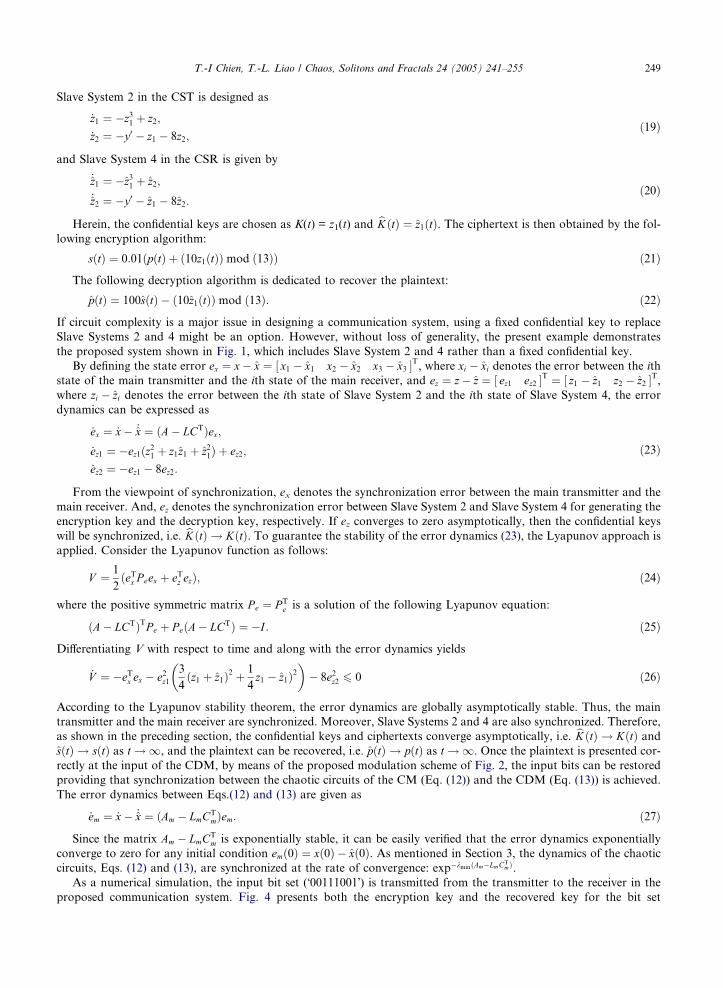
As a numerical simulation, the input bit set (�00111001�) is transmitted from the transmitter to the receiver in the
proposed communication system. Fig. 4 presents both the encryption key and the recovered key for the bit set
0 5 10 15 20 25 30 35 40 45-0.8
-0.6
-0.4
-0.2
0
0.2
0.4
0.6
Time
Am
plitu
de
The encryption key(dashed) and the recovered one(dash dot)
Fig. 4. The encryption key (dashed) and the recovered one (dash–dot).
0 5 10 15 20 25 30 35 40 45-0.02
0
0.02
0.04
0.06
0.08
0.1
0.12
0.14
0.16
Time
Am
plitu
de
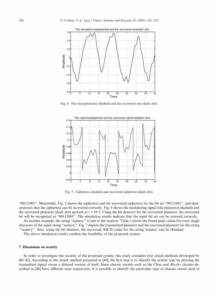
The ciphertext(dashed) and the recovered ciphertext(dash-dot)
Fig. 5. Ciphertext (dashed) and recovered ciphertext (dash–dot).
250 T.-I Chien, T.-L. Liao / Chaos, Solitons and Fractals 24 (2005) 241–255
‘‘00111001’’. Meanwhile, Fig. 5 shows the ciphertext and the recovered ciphertext for the bit set ‘‘00111001’’, and dem-
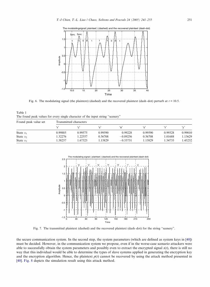
onstrates that the ciphertext can be recovered correctly. Fig. 6 shows the modulating signal (the plaintext) (dashed) and
the recovered plaintext (dash–dot) perturb at t = 10.5. Using the bit detector for the recovered plaintext, the recovered
bit will be recognized as ‘‘00111001’’. The simulation results indicate that the input bit set can be restored correctly.
As another example, the string ‘‘scenery’’ is sent to the receiver. Table 1 shows the found peak values for every single
character of the input string ‘‘scenery’’. Fig. 7 depicts the transmitted plaintext and the recovered plaintext for the string
‘‘�scenery’’. Also, using the bit detector, the recovered ASCII codes for the string �scenery� can be obtained.
The above simulation results confirm the feasibility of the proposed system.
7. Discussions on security
In order to investigate the security of the proposed system, this study considers four attack methods developed by
[40–42]. According to the attack method presented in [40], the first step is to identify the system type by plotting the
transmitted signal versus a delayed version of itself. Since chaotic circuits such as the Chua and Rossler circuits de-
scribed in [40] have different state trajectories, it is possible to identify the particular type of chaotic circuit used in
10.5 15 20 25 30 35 40-1.5
-1
-0.5
0
0.5
1
1.5
2The modulatingsignal( plaintext ) (dashed) and the recovered plaintext (dash-dot)
Time
Am
plitu
de
1 01 1 1 1 10 0 0
Sync. Sync.
Fig. 6. The modulating signal (the plaintext) (dashed) and the recovered plaintext (dash–dot) perturb at t = 10.5.
Table 1
The found peak values for every single character of the input string ‘‘scenery’’
Found peak value set Transmitted characters
�s� �c� �e� �n� �e� �r� �y�
State x1 0.99885 0.99575 0.99590 0.99228 0.99590 0.99328 0.99010
State x2 1.32276 1.22557 0.56708 �0.89256 0.56708 1.01688 1.13629
State x3 1.58257 1.67325 1.15829 �0.53731 1.15829 1.54735 1.45232
0 30 60 90 120 150 180 210 250-1.5
-1
-0.5
0
0.5
1
1.5
2
2.5
Time
Am
plitu
de
The modulating signal ( plaintext ) (dashed) and the recovered plaintext (dash-dot)
's' 'c' 'e' 'e' 'n' 'r' 'y'
Fig. 7. The transmitted plaintext (dashed) and the recovered plaintext (dash–dot) for the string ‘‘scenery’’.
T.-I Chien, T.-L. Liao / Chaos, Solitons and Fractals 24 (2005) 241–255 251
the secure communication system. In the second step, the system parameters (which are defined as system keys in [40])
must be decided. However, in the communication system we propose, even if in the worse-case scenario attackers were
able to successfully obtain the system parameters and possibly even to extract the encrypted signal s(t), there is still no
way that this individual would be able to determine the types of slave systems applied in generating the encryption key
and the encryption algorithm. Hence, the plaintext p(t) cannot be recovered by using the attack method presented in
[40]. Fig. 8 depicts the simulation result using this attack method.
0 30 60 90 120 150 180 210 250-1.5
-1
-0.5
0
0.5
1
1.5
2
2.5
Time
Am
plitu
de
The modulating signal ( plaintext ) (dashed) and the recovered plaintext (solid) using the attack method in Ref. [40]
Fig. 8. The transmitted plaintext (dashed) and the recovered plaintext (solid) using the attack method in [40].
252 T.-I Chien, T.-L. Liao / Chaos, Solitons and Fractals 24 (2005) 241–255
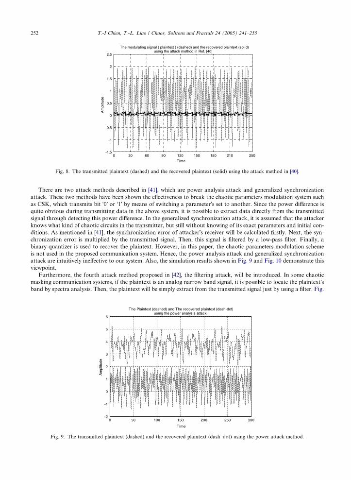
There are two attack methods described in [41], which are power analysis attack and generalized synchronization
attack. These two methods have been shown the effectiveness to break the chaotic parameters modulation system such
as CSK, which transmits bit �0� or �1� by means of switching a parameter�s set to another. Since the power difference is
quite obvious during transmitting data in the above system, it is possible to extract data directly from the transmitted
signal through detecting this power difference. In the generalized synchronization attack, it is assumed that the attacker
knows what kind of chaotic circuits in the transmitter, but still without knowing of its exact parameters and initial con-
ditions. As mentioned in [41], the synchronization error of attacker�s receiver will be calculated firstly. Next, the syn-
chronization error is multiplied by the transmitted signal. Then, this signal is filtered by a low-pass filter. Finally, a
binary quantizer is used to recover the plaintext. However, in this paper, the chaotic parameters modulation scheme
is not used in the proposed communication system. Hence, the power analysis attack and generalized synchronization
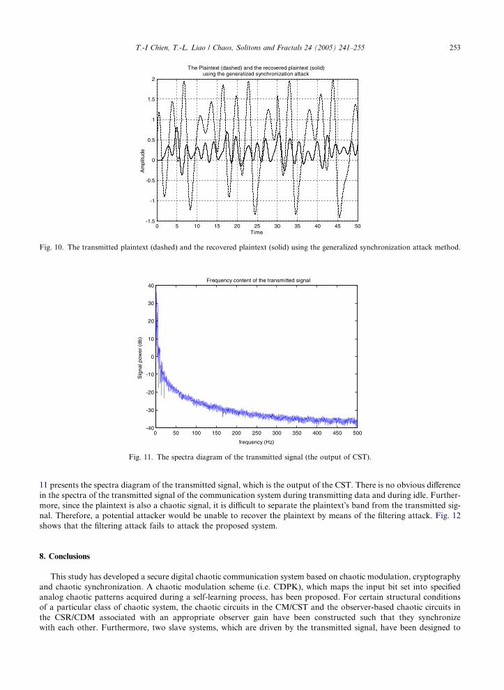
attack are intuitively ineffective to our system. Also, the simulation results shown in Fig. 9 and Fig. 10 demonstrate this
viewpoint.
Furthermore, the fourth attack method proposed in [42], the filtering attack, will be introduced. In some chaotic
masking communication systems, if the plaintext is an analog narrow band signal, it is possible to locate the plaintext�sband by spectra analysis. Then, the plaintext will be simply extract from the transmitted signal just by using a filter. Fig.
0 50 100 150 200 250 300-2
-1
0
1
2
3
4
5
6
Time
Am
plitu
de
The Plaintext (dashed) and The recovered plaintext (dash-dot) using the power analysis attack
Fig. 9. The transmitted plaintext (dashed) and the recovered plaintext (dash–dot) using the power attack method.
0 5 10 15 20 25 30 35 40 45 50-1.5
-1
-0.5
0
0.5
1
1.5
2
Time
Am
plitu
de
The Plaintext (dashed) and the recovered plaintext (solid) using the generalized synchronization attack
Fig. 10. The transmitted plaintext (dashed) and the recovered plaintext (solid) using the generalized synchronization attack method.
0 50 100 150 200 250 300 350 400 450 500-40
-30
-20
-10
0
10
20
30
40Frequency content of the transmitted signal
frequency (Hz)
Sig
nal p
ower
(db
)
Fig. 11. The spectra diagram of the transmitted signal (the output of CST).
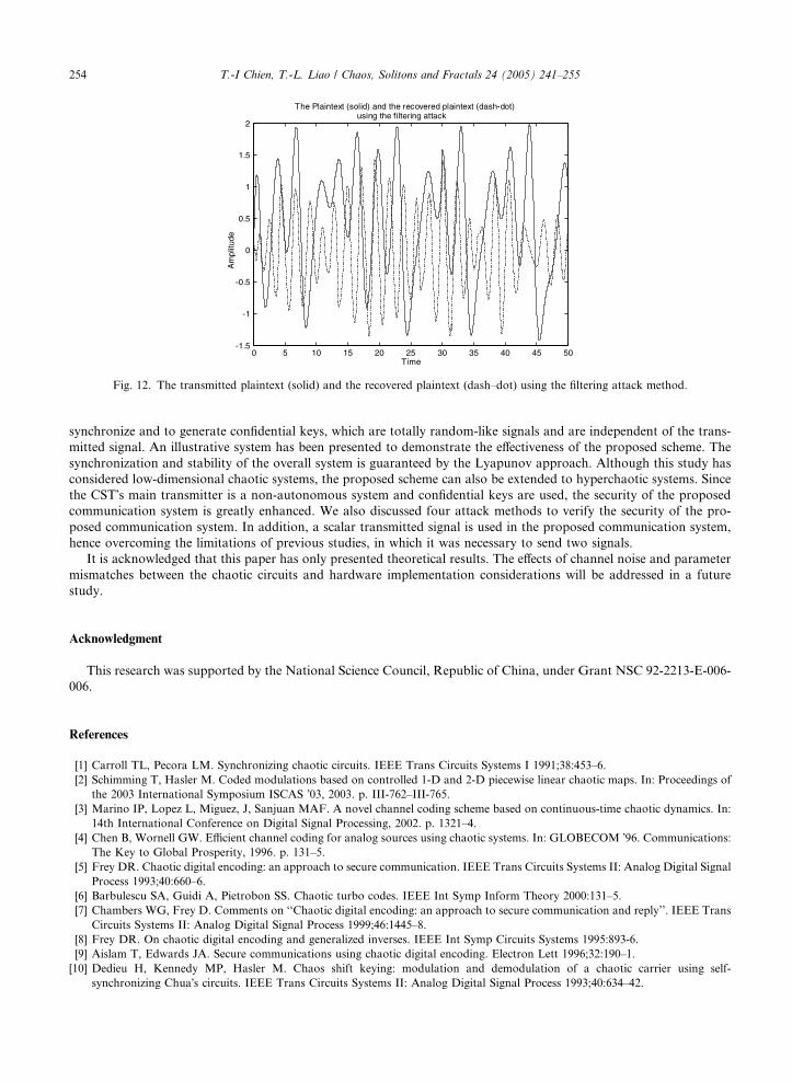
T.-I Chien, T.-L. Liao / Chaos, Solitons and Fractals 24 (2005) 241–255 253
11 presents the spectra diagram of the transmitted signal, which is the output of the CST. There is no obvious difference
in the spectra of the transmitted signal of the communication system during transmitting data and during idle. Further-
more, since the plaintext is also a chaotic signal, it is difficult to separate the plaintext�s band from the transmitted sig-
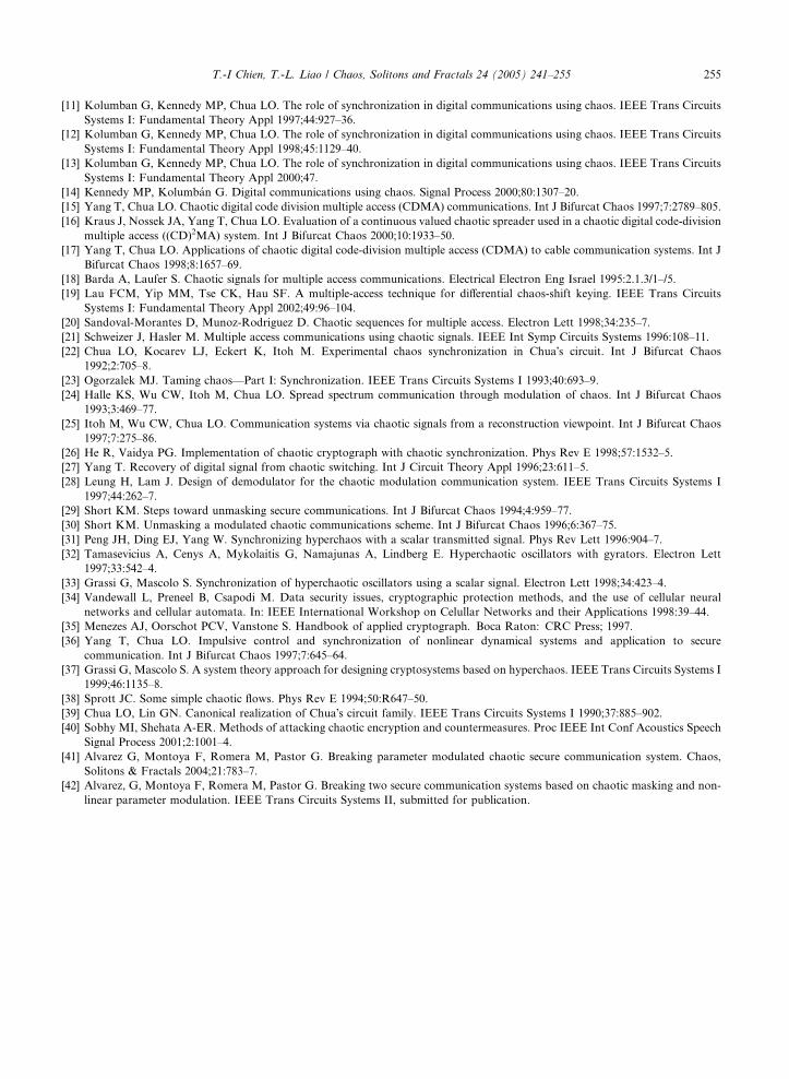
nal. Therefore, a potential attacker would be unable to recover the plaintext by means of the filtering attack. Fig. 12
shows that the filtering attack fails to attack the proposed system.
8. Conclusions
This study has developed a secure digital chaotic communication system based on chaotic modulation, cryptography
and chaotic synchronization. A chaotic modulation scheme (i.e. CDPK), which maps the input bit set into specified
analog chaotic patterns acquired during a self-learning process, has been proposed. For certain structural conditions
of a particular class of chaotic system, the chaotic circuits in the CM/CST and the observer-based chaotic circuits in
the CSR/CDM associated with an appropriate observer gain have been constructed such that they synchronize
with each other. Furthermore, two slave systems, which are driven by the transmitted signal, have been designed to
0 5 10 15 20 25 30 35 40 45 50-1.5
-1
-0.5
0
0.5
1
1.5
2
Time
Am
plitu
de
The Plaintext (solid) and the recovered plaintext (dash-dot)using the filtering attack
Fig. 12. The transmitted plaintext (solid) and the recovered plaintext (dash–dot) using the filtering attack method.
254 T.-I Chien, T.-L. Liao / Chaos, Solitons and Fractals 24 (2005) 241–255
synchronize and to generate confidential keys, which are totally random-like signals and are independent of the trans-
mitted signal. An illustrative system has been presented to demonstrate the effectiveness of the proposed scheme. The
synchronization and stability of the overall system is guaranteed by the Lyapunov approach. Although this study has
considered low-dimensional chaotic systems, the proposed scheme can also be extended to hyperchaotic systems. Since
the CST�s main transmitter is a non-autonomous system and confidential keys are used, the security of the proposed
communication system is greatly enhanced. We also discussed four attack methods to verify the security of the pro-
posed communication system. In addition, a scalar transmitted signal is used in the proposed communication system,
hence overcoming the limitations of previous studies, in which it was necessary to send two signals.
It is acknowledged that this paper has only presented theoretical results. The effects of channel noise and parameter
mismatches between the chaotic circuits and hardware implementation considerations will be addressed in a future
study.
Acknowledgment
This research was supported by the National Science Council, Republic of China, under Grant NSC 92-2213-E-006-
006.
References
[1] Carroll TL, Pecora LM. Synchronizing chaotic circuits. IEEE Trans Circuits Systems I 1991;38:453–6.
[2] Schimming T, Hasler M. Coded modulations based on controlled 1-D and 2-D piecewise linear chaotic maps. In: Proceedings of
the 2003 International Symposium ISCAS �03, 2003. p. III-762–III-765.[3] Marino IP, Lopez L, Miguez, J, Sanjuan MAF. A novel channel coding scheme based on continuous-time chaotic dynamics. In:
14th International Conference on Digital Signal Processing, 2002. p. 1321–4.
[4] Chen B, Wornell GW. Efficient channel coding for analog sources using chaotic systems. In: GLOBECOM �96. Communications:
The Key to Global Prosperity, 1996. p. 131–5.
[5] Frey DR. Chaotic digital encoding: an approach to secure communication. IEEE Trans Circuits Systems II: Analog Digital Signal
Process 1993;40:660–6.
[6] Barbulescu SA, Guidi A, Pietrobon SS. Chaotic turbo codes. IEEE Int Symp Inform Theory 2000:131–5.
[7] Chambers WG, Frey D. Comments on ‘‘Chaotic digital encoding: an approach to secure communication and reply’’. IEEE Trans
Circuits Systems II: Analog Digital Signal Process 1999;46:1445–8.
[8] Frey DR. On chaotic digital encoding and generalized inverses. IEEE Int Symp Circuits Systems 1995:893-6.
[9] Aislam T, Edwards JA. Secure communications using chaotic digital encoding. Electron Lett 1996;32:190–1.
[10] Dedieu H, Kennedy MP, Hasler M. Chaos shift keying: modulation and demodulation of a chaotic carrier using self-
synchronizing Chua�s circuits. IEEE Trans Circuits Systems II: Analog Digital Signal Process 1993;40:634–42.
T.-I Chien, T.-L. Liao / Chaos, Solitons and Fractals 24 (2005) 241–255 255
[11] Kolumban G, Kennedy MP, Chua LO. The role of synchronization in digital communications using chaos. IEEE Trans Circuits
Systems I: Fundamental Theory Appl 1997;44:927–36.
[12] Kolumban G, Kennedy MP, Chua LO. The role of synchronization in digital communications using chaos. IEEE Trans Circuits
Systems I: Fundamental Theory Appl 1998;45:1129–40.
[13] Kolumban G, Kennedy MP, Chua LO. The role of synchronization in digital communications using chaos. IEEE Trans Circuits
Systems I: Fundamental Theory Appl 2000;47.
[14] Kennedy MP, Kolumban G. Digital communications using chaos. Signal Process 2000;80:1307–20.
[15] Yang T, Chua LO. Chaotic digital code division multiple access (CDMA) communications. Int J Bifurcat Chaos 1997;7:2789–805.
[16] Kraus J, Nossek JA, Yang T, Chua LO. Evaluation of a continuous valued chaotic spreader used in a chaotic digital code-division
multiple access ((CD)2MA) system. Int J Bifurcat Chaos 2000;10:1933–50.
[17] Yang T, Chua LO. Applications of chaotic digital code-division multiple access (CDMA) to cable communication systems. Int J
Bifurcat Chaos 1998;8:1657–69.
[18] Barda A, Laufer S. Chaotic signals for multiple access communications. Electrical Electron Eng Israel 1995:2.1.3/1–/5.
[19] Lau FCM, Yip MM, Tse CK, Hau SF. A multiple-access technique for differential chaos-shift keying. IEEE Trans Circuits
Systems I: Fundamental Theory Appl 2002;49:96–104.
[20] Sandoval-Morantes D, Munoz-Rodriguez D. Chaotic sequences for multiple access. Electron Lett 1998;34:235–7.
[21] Schweizer J, Hasler M. Multiple access communications using chaotic signals. IEEE Int Symp Circuits Systems 1996:108–11.
[22] Chua LO, Kocarev LJ, Eckert K, Itoh M. Experimental chaos synchronization in Chua�s circuit. Int J Bifurcat Chaos
1992;2:705–8.
[23] Ogorzalek MJ. Taming chaos—Part I: Synchronization. IEEE Trans Circuits Systems I 1993;40:693–9.
[24] Halle KS, Wu CW, Itoh M, Chua LO. Spread spectrum communication through modulation of chaos. Int J Bifurcat Chaos
1993;3:469–77.
[25] Itoh M, Wu CW, Chua LO. Communication systems via chaotic signals from a reconstruction viewpoint. Int J Bifurcat Chaos
1997;7:275–86.
[26] He R, Vaidya PG. Implementation of chaotic cryptograph with chaotic synchronization. Phys Rev E 1998;57:1532–5.
[27] Yang T. Recovery of digital signal from chaotic switching. Int J Circuit Theory Appl 1996;23:611–5.
[28] Leung H, Lam J. Design of demodulator for the chaotic modulation communication system. IEEE Trans Circuits Systems I
1997;44:262–7.
[29] Short KM. Steps toward unmasking secure communications. Int J Bifurcat Chaos 1994;4:959–77.
[30] Short KM. Unmasking a modulated chaotic communications scheme. Int J Bifurcat Chaos 1996;6:367–75.
[31] Peng JH, Ding EJ, Yang W. Synchronizing hyperchaos with a scalar transmitted signal. Phys Rev Lett 1996:904–7.
[32] Tamasevicius A, Cenys A, Mykolaitis G, Namajunas A, Lindberg E. Hyperchaotic oscillators with gyrators. Electron Lett
1997;33:542–4.
[33] Grassi G, Mascolo S. Synchronization of hyperchaotic oscillators using a scalar signal. Electron Lett 1998;34:423–4.
[34] Vandewall L, Preneel B, Csapodi M. Data security issues, cryptographic protection methods, and the use of cellular neural
networks and cellular automata. In: IEEE International Workshop on Celullar Networks and their Applications 1998:39–44.
[35] Menezes AJ, Oorschot PCV, Vanstone S. Handbook of applied cryptograph. Boca Raton: CRC Press; 1997.
[36] Yang T, Chua LO. Impulsive control and synchronization of nonlinear dynamical systems and application to secure
communication. Int J Bifurcat Chaos 1997;7:645–64.
[37] Grassi G, Mascolo S. A system theory approach for designing cryptosystems based on hyperchaos. IEEE Trans Circuits Systems I
1999;46:1135–8.
[38] Sprott JC. Some simple chaotic flows. Phys Rev E 1994;50:R647–50.
[39] Chua LO, Lin GN. Canonical realization of Chua�s circuit family. IEEE Trans Circuits Systems I 1990;37:885–902.
[40] Sobhy MI, Shehata A-ER. Methods of attacking chaotic encryption and countermeasures. Proc IEEE Int Conf Acoustics Speech
Signal Process 2001;2:1001–4.
[41] Alvarez G, Montoya F, Romera M, Pastor G. Breaking parameter modulated chaotic secure communication system. Chaos,
Solitons & Fractals 2004;21:783–7.
[42] Alvarez, G, Montoya F, Romera M, Pastor G. Breaking two secure communication systems based on chaotic masking and non-
linear parameter modulation. IEEE Trans Circuits Systems II, submitted for publication.