Embed Size (px)
Citation preview
Design of Power Steering Systems forHeavy-Duty Long-Haul Vehicles
Emilia Silvas ∗ Eric Backx ∗ Theo Hofman ∗ Henk Voets ∗∗
Maarten Steinbuch ∗
∗ Eindhoven University of Technology, Control Systems TechnologyGroup, Mechanical Engineering Dept., P.O. Box 513, 5600 MB
Eindhoven, The Netherlands.(email: [email protected])∗∗DAF Trucks N.V.,P.O. Box 90065,5600 PT Eindhoven,The
Netherlands.
Abstract: Conventionally, all auxiliaries present in a heavy-duty vehicle (e.g., power-steeringpump, air-conditioning compressor) are engine-driven systems, which put high constraints ontheir performance. Outputs (e.g., speed, temperature) and energy consumption are dictated byengine speed, while most auxiliary demands are not proportional to the engine speed. Dealingwith worst-case scenarios leads to highly oversized components that further, dramatically reducethe overall efficiency. How to choose, in a simultaneous design step, a topology, component sizesand a control algorithm for auxiliaries is still unknown. This becomes, especially, importantwhen an integrated general optimal design is desired for the vehicle rather than an optimalsystem or sub-system design. To overcome the drawbacks of a sequential design approach, thispaper shows the precise combination of technology, topology, size and control for the powersteering system used in a heavy-duty vehicle. Modeling of six possible topologies and optimalsizing of components, as the gear ratio between combustion engine and power steering pump,are shown. Next, a sensitivity analysis is done for control parameters and a view is presentedon a suitable topology for a power steering system used in a heavy-duty long-haul vehicle.
Keywords: Optimal Design, Power Steering Pump, Electrical (Assisted) Steering
1. INTRODUCTION
The possibility of electrifying various components of avehicle, aiming at reducing fuel, emissions, cost or increaseperformance, is an increasing field of research. Supportedby the grow in popularity of the hybrid electric vehicle(HEV), this enables the transition from relative less effi-cient (hydraulic, or engine driven systems) to more efficient(electric mechanical, electric machine (EM) driven) com-ponents. A HEV refers to the combination of one or moreEMs with one energy carrier as the Combustion Engine(CE), but can also represent, referred to as a hybrid vehicle(HV), any other combination of two power sources. Withinboth hybrid and conventional vehicles, depending on theapplication, the auxiliaries consume significant amounts offuel. Previous research articles show power consumptionestimates of auxiliaries for various commercial vehicles,but none of these papers addresses the problem of optimaldesign for these units. This implies the optimal selectionof topology, technology, sizes and control algorithm, Silvaset al. [2012]. For instance, Kluger and Harris [2007] showthat auxiliary units consume between 3% and 11% forheavy-duty trucks and between 8% and 15% for mini-vans;Pettersson and Johansson [2006] show between 5% and 7%for a Scania truck, while a report from US-Council [2010]shows that this consumption can be up to 25% of thetotal power for a transit bus. Naturally, one might expectvarious percentages since the power requirements of differ-ent auxiliaries vary with respect to the application area,
functionalities, environmental factors(e.g., temperature)and different duty cycles. Moreover, these consumptionestimates do not account for the energy required to drivethe auxiliaries, which makes a significant difference for anewly developed system. Therefore, finding the optimaldesign for these auxiliaries constitutes both a challengingresearch area as well as a commercial interest for manu-factures.
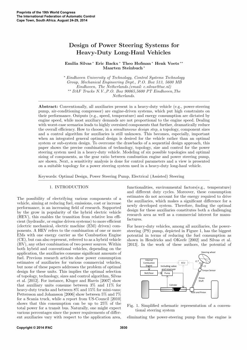
For heavy-duty vehicles, among all auxiliaries, the power-steering (PS) pump, depicted in Figure 1, has the biggestpotential in terms of reducing the fuel consumption asshown in Hendricks and OKeefe [2002] and Silvas et al.[2013]. In the work of these authors, the potential of
𝛿, 𝑇
Cylinder
Steering wheel
Torque Sensor
Rack and Pinion
Internal Combustion
Engine
Pinion Shaft
Belt/Gear Pump
ECU
Including valve and reservoir
Fig. 1. Simplified schematic representation of a conven-tional steering system
eliminating the power-steering pump from the engine is
Preprints of the 19th World CongressThe International Federation of Automatic ControlCape Town, South Africa. August 24-29, 2014
Copyright © 2014 IFAC 3930
shown (Hendricks and OKeefe [2002]) as well as addingit back to the driveline via the alternator (Silvas et al.[2013]). In recent works by Hu et al. [2008], El-Shaeret al. [2009], Chen et al. [2008], Liu et al. [2008] severalcontrollers are designed for PS systems, particularly forelectric-power assisted steering (EPS), used in passengervehicles. These controllers are built based on priorly givenhardware (i.e. topology, technology and size) and focuson steering performance, the steering feel of the driver orother challenges as summarized in Gruner et al. [2008].Recent research for the main power-train componentsshows that this sequential design approach, as definedby Fathy et al. [2001], can be improved if also topology,technology and size are considered integrated with thecontroller design. As an alternative solution for passengervehicles, an electro-hydraulic PS system is presented inKemmetmuller et al. [2007]. Here, when compared witha traditional hydraulic power-steering system, up to 75%reduction in fuel consumption is shown for the NEDC(New European Driving Cycle) driving cycle. Followingthese works the question remains on how one can choosefor the optimal topology and sizes for the steering systemand its sub-systems, for both conventional and hybridpower-trains.
In this paper an analysis is done for the PS system, wheresix configurations are developed (including conventionalhydraulic pump, electrically driven hydraulic pump, elec-trically steering systems and more complex configurationsderived from these) and the optimization problem is de-fined to find the component sizes. Next, the fuel consump-tion is calculated for various constant flows within the thepump and various driving cycles. Finally, based on the pre-sented results, indications are given on the applicability ofeach topology to a particular vehicle class and conclusionsare drawn.
2. OPTIMAL DESIGN OF STEERING SYSTEMS
From a general perspective the problem of optimallydesigning a hybrid vehicle, constitutes an multi-objectiveoptimization problem with a tremendously big designspace, as motivated in Silvas et al. [2012], and with amultidisciplinary character, Allison and Herbery [2013].This can be particularized to PS systems as depicted inFigure 2 and will be defined in the sections that follow.
• Hydraulic pump
• Electric Machine
• Variable Flow
• Fault Tolerant
• Robust (…)
• Conventional
• Electro-hydraulic
• Electric assist
• Dual
• Power-split
• Electric Machine
• Hydraulic pump
• Gear ratio between CE and pump
• PGS
Size
Control
Hybrid Truck
Combustion Engine
driven Truck
Fuel
Emission
Performance
Comfort, Handling,
Safety
Cost
Application Parameters Targets /
Constraints
(pre
dic
ted
) o
pe
rati
on
co
nd
itio
ns
Technology
Topology
Fig. 2. Steering system design problem for heavy-duty(hybrid) vehicles
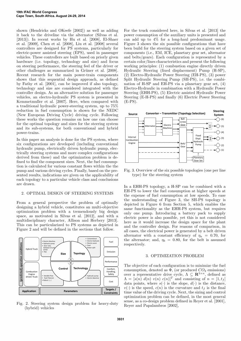
For the truck considered here, in Silvas et al. [2013] thepower consumption of the auxiliary units is presented andcan add up to 4% for a long-haul predominant usage.Figure 3 shows the six possible configurations that havebeen build for the steering system based on a given set ofcomponents (i.e., EM, ICE, planetary gear set, alternatorand belts/gears). Each configuration is represented by acertain color/lines characteristics and present the followingworking principles: (1) combustion engine directly drivenHydraulic Steering (fixed displacement) Pump (H-SP),(2) Electro-Hydraulic Power Steering (EH-PS), (3) powerSplit Hydraulic Steering Pump (SH-PS), i.e. the combi-nation of H-SP and EH-PS via a planetary gear set, (4)Electro-Hydraulic in combination with a Hydraulic PowerSteering (EHH-PS), (5) Electric assisted Hydraulic PowerSteering (E-H-PS) and finally (6) Electric Power Steering(E-PS).
Belt/Gear
Electric Machine
Steering SystemConverter – Transmitter (Topology Selection)
Internal Combustion
Engine
Alternator
Source
Fixed Displ.
Hydraulic Pump
Ball-screw Gear
Planetary Gear Set
∑
∑
(1)
(2)
(3)
(4)
(5)
(6)
Fig. 3. Overview of the six possible topologies (one per linetype) for the steering system
In a EHH-PS topology, a H-SP can be combined with aEH-PS to lower the fuel consumption at higher speeds atthe expense of fuel consumption at low speeds. To easethe understanding of Figure 3, the SH-PS topology isdepicted in Figure 6 from Section 5, which enables thesame functionality as the EHH-PS system, but requiresonly one pump. Introducing a battery pack to supplyelectric power is also possible, yet this is not consideredhere as it would increase the design space for the plantand the controller design. For reasons of comparison, inall cases, the electrical power is generated by a belt drivenalternator with a constant efficiency of ηa = 0.70, forthe alternator; and, ηb = 0.80, for the belt is assumedrespectively.
3. OPTIMIZATION PROBLEM
The objective of each configuration is to minimize the fuelconsumption, denoted as Φ, (or produced CO2 emissions)over a representative drive cycle, Λ ⊆ R3×n, defined asΛ = [s(n) d(n) v(n) c(n)]T and consisting of n = [1, tf ]data points, where s(·) is the slope, d(·) is the distance,v(·) is the speed, c(n) is the curvature and tf is the finaltime value of the driving cycle. Next, the sizing and controloptimization problem can be defined, in the most generalsense, as a co-design problem defined in Reyer et al. [2001],Reyer and Papalambros [2002],
19th IFAC World CongressCape Town, South Africa. August 24-29, 2014
3931
minxc,xd⊆X⊆R1×n
J = minxc,xd⊆X
∫ tf
0
Φc,d(xc(t), xd)dt,
s.t. gd,c(xc(t), xd) ≤ 0,
hd,c(xc(t), xd) = 0.
(1)
Here (·)d denotes a parametric sizing variable and (·)cdenotes a control variable. Depending on the topology,the design variables (xc, xd), detailed in Table 1, and theobjective to be minimized, Φc,d, are
xc = {fh, fn}, (2)
xd = {i1, i2, Pe, z, l, A}, (3)
fd,c = Φ(xc, xd) = mf , (4)
fd,c : R1xn ×R1xn 7→ R1xn, (5)
with mf the fuel mass flow rate.
Table 1. Optimization Design Variables
Design variable Symbol UnitsFixed gear ratio (ICE-pump) i1 −Electric machine rated power Pe kWFixed gear ratio (EM-pump) i2 −Fixed gear ratio PGS z −Ball-screw lead l m/revSteering house piston area A m2
Min. const. flow on highway fh L/minMin. const. flow on national roads fn L/min
In Table 2 the set of design variables, for each topology,are depicted. The set of inequality constraints, gd,c, andequality constraints, hd,c, are dictated by the physicalproperties of the system and they must be defined foreach configuration in Figure 3. An example, for a complextopology is shown in the results section. When xc 6= ∅ theoutput flow (fh and fn) of the electrically driven pumpcan be varied. For example, when there is no input at thesteering wheel while driving on the highway, the flow canbe reduced in order to save energy.
Table 2. Design Variables for each topology
Variable i1 Pe i2 z l A fh fnTopology 1 �Topology 2 � � � �Topology 3 � � � � � �Topology 4 � � � � �Topology 5 � � � �Topology 6 � � �
Ideally, this problem can be solved by a simultaneous opti-mization problem which, if any, will provide the global op-timum value for the control and sizing parameters searchedat the cost of high computational time. Here, next, thisproblem is split into a nested (bi-level) optimization prob-lem, concept defined by H.K. Fathy and Ulsog [2001],where the optimal sizing is solved by
minxd⊆X⊆R1×n
Jd =
mini1,i2,Pe,z,l,A⊆X
∫ tf
0
mf (i1, i2, Pe, z, l, A)dt,
s.t. gd(i1, i2, Pe, z, l, A) ≤ 0,
hd(i1, i2, Pe, z, l, A) = 0,
(6)
and the control problem is solved by
minxc⊆X⊆R1×n
Jc = minfh,fn⊆X
∫ tf
0
mf (fh, fn)dt,
s.t. gc(fh, fn) ≤ 0,
hc(fh, fn) = 0.
(7)
To avoid the optimization algorithm getting stuck in alocal minimum, a derivative free optimization algorithmis most suitable for these design problems. The downsideof these algorithms is that they generally require (very)large computation times. To overcome the problem of(non)convergence of the global optimal solution, for thesizing problem, we solve (6) using a brute-force searchover the design vectors. Then, with the same approach,in a nested manner, for each chosen set of xd the controlproblem is solved for a discrete grid of fh and fd. Whenusing a brute-force search method the design space issubdivided into an equidistant grid for each dimension andthe objective function is evaluated for all feasible points inthis grid. Although this method will not provide as output,the true global minimum, it will enable one to makea comparison between different designs. Moreover, themethod is straightforward, suitable for low-dimensionaloptimization problems where only indicative values arerequire and represents a good starting method to fullyunderstand the complexity of the problem. Given the highnumber of design variables, insights on the optimal designproblem should be given in a Pareto distribution form.This offers insight into the optimal design set and leaves acertain degree of freedom to the designer as-well.
4. MODELING OF POWER STEERINGTOPOLOGIES
In general, there exist three types of pump models: (i) em-pirical models, based on measured data, are particularlyuseful when an accurate representation of a particular,existing pump is required, (ii) physical models, sometimesless accurate for a particular pump but more uniform, andhence more useful for new pump development, and (iii)analytical (or coefficient) models, that can be seen as acombination of the first two. In this latest model typeonly a limited amount of measurement data is used todetermine coefficients that result from physical relations.
Due to limited amount of available data from the realpump, here, the analytical models will be built that includeboth leakage losses, (caused by the small gaps between thevanes and the housing) and torque losses, Tl, (induced byfriction). The required, effective torque, Te, and the hydro-mechanical efficiency, ηhm, of the pump are defined by
Te = Ti + Tl, (8)
ηhm =TiTe, (9)
where Ti is the ideal pump torque, a function of pres-sure and angular speed. The amount of leakage flow, ql,and friction torque (and therewith volumetric and hydro-mechanical efficiency) depend on operating conditions, i.e.
ql = ql(∆p, ω, θ, p, µ, ...),
Tl = Tl(∆p, ω, θ, p, µ, ...),(10)
19th IFAC World CongressCape Town, South Africa. August 24-29, 2014
3932
where ∆p is the pressure difference across the pump, θ isthe operating temperature and µ is the dynamic viscosityof the fluid.
The hydro-mechanical efficiency, ηhm, and the total ef-ficiency from mechanical to hydraulic power, ηtot, arefurther deduced from a four-pole notation as
Pm = T · ω (11)
= ∆p · 1/ηhm ·D · ω, (12)
ηhm =∆p ·DT
, (13)
Ph = ∆p · q (14)
= ∆p ·D · ηv · ω, (15)
ηtot = Ph/Pm (16)
=∆p ·D · ηv · ω
∆p · 1ηhm·D · ω
(17)
= ηhm · ηv, (18)
where Pm is the mechanical input power, Ph is the hy-draulic output power of the pump, D is the instantaneousdisplacement volume and ηv is the volumetric efficiency.Next, this structure, consisting of a volumetric and ahydro-mechanical efficiency, is used to describe the fixeddisplacement pump for all topologies. Results for modelingand validation of a fixed displacement pump have beenshown by the authors in Silvas et al. [2013].
Mathematical descriptions of these PS systems are buildand validated. Scaling of the EM is done using linearscaling. When there are no variables to be controlled,the optimal design problem boils down to a one degreeof freedom optimization problem (PSP, E-HPS and EPStopologies).
4.1 Duty cycle
For each topology, the solution to the design optimizationproblem depends on the duty cycle of the PS system.Sequentially, the duty cycle is drive cycle dependent andtherefore the optimal solution for inner city driving willnot always equal the optimal solution for highway driving.For the results presented here, focused on long-haul usage,a mixed cycle measured on a fully loaded tractor-traileris used, that combines various road segments, with apredominant (85%) highway driving.
5. SIMULATION RESULTS FOR THE OPTIMALSIZING AND CONTROL
5.1 Variable flow control for the hydraulic pump
The EH-PS, SH-PS and the EHH-PS topologies enable acontrolled oil flow, which means that the output flow ofthe electrically driven pump, φ, can be varied dependingon driving conditions. For example, when there is no inputat the steering wheel while driving on the highway, the flowcan be reduced in order to save energy. The minimum flow(fh, fn) at certain driving conditions is restricted by safetyreasons as it takes some time before the pump delivers therequired flow and pressure when it is accelerated from astand-by mode. Since the flow reduction capability is an
important benefit of these topologies, it has been includedby means of different use cases. In the first three use cases,the flow is varied when driving on highways and nationalroads as: (flow I)fh = 11, fn = 16, (flow II)fh = 6, fn = 16and (flow III) fh = 6, fn = 11 . On the drive cyclesthat are used for the simulations, these flows are sufficientthroughout the cycles. The fourth use case serves as a lowerbound of what is achievable when the flow could be variedexactly according to the steering wheel input. This usecase (flow IV) is applied on all the drive cycles and can bedescribed mathematically as
φ =
⟨φr, for φr > 6 L/min;
6 L/min for φr ≤ 6 L/min,(19)
with φr the required flow.
5.2 Pareto analysis per-topology
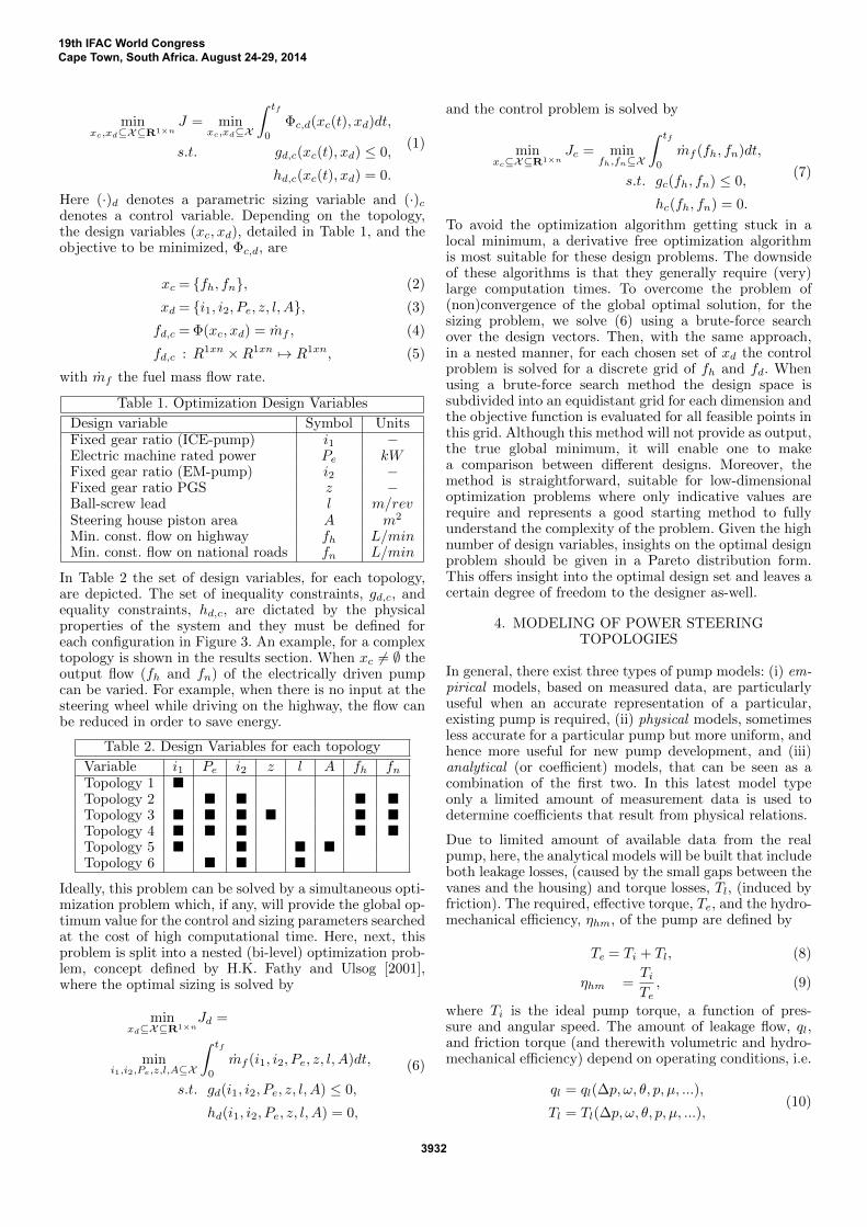
For the first given topology (H-PS), the results for usingthis method are graphically depicted in Figure 4, whereone can observe that the lowest feasible gear ratio results inthe lowest average fuel consumption. As this topology hasno control freedom, solving (1) boils down to a one degreeof freedom optimization problem (2), with xd = {i1} andan active constraints given by
qmin −D · i1 · ωi + kl · psh ≤ 0, (20)
where qmin is the minimum flow, ωi is the CE idling speed,psh is the steering house pressure and kl is the leakageflow coefficient. For this optimization the grid size perdimension is 20 and the simulation time is 15 minutes. Theminimum flow at certain driving conditions is restrictedby safety reasons. It is assumed that variable flow canonly be applied when driving on highway or national road,since on other roads the steering duty cycle is much higher.When more variables are to be optimized a Pareto frontier
(Scaled) Gear ratio, i1 [−]
(Sca
led)
Ave
rage
fuel
con
sum
ptio
n, Φ
, [L/
100k
m]
1,5 1,6 1,7 1,8 1,9 2,03.6
7.2Infeasible RegionMinimum Flow Constraint
Fuel consumption, ΦOptimal gear ration, i
1
Fig. 4. Pareto front for optimal gear selection in the H-SPTopology
set for the design solutions can be found. This impliesthat it is impossible to chose for a more optimal solutionfor one design variable without making another designvariable worse. Such a result is depicted in Figure 5 forthe second topology, EH-PS. This tradeoff is by itself aresult and can help in creating a prediction of how wouldthe fuel consumption change with an increase in the gearratio or the motor power. For this case, one could observethat with an increase of EM power also an increase inthe gear used is required in order to keep the low fuel
19th IFAC World CongressCape Town, South Africa. August 24-29, 2014
3933
Gear ratio i2 [−]
Ele
ctric
mot
or r
ated
pow
er, P
EM
, [kW
]
0 0.05 0.1 0.15 0.2 0.25 0.3 0.35 0.45
10
15
Infeasible regionNot simulatedMotor speed constraintMotor torque constraintFuel consumption
0.6
0.7
0.8
0.9
1
1.1
1.2
1.3
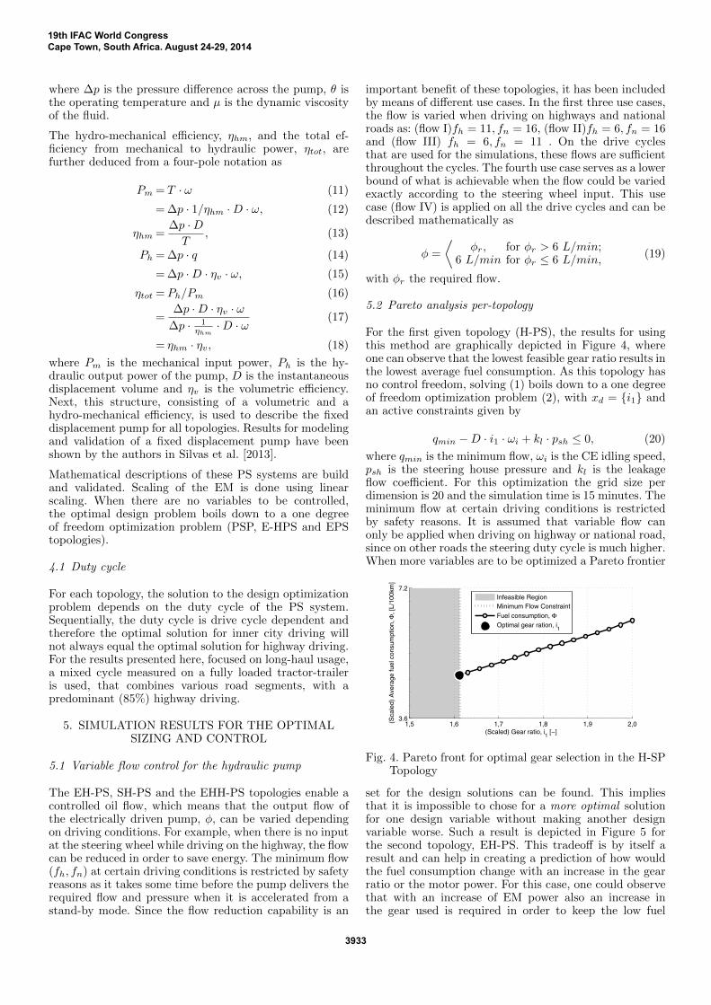
Fig. 5. Optimal size selection of the EH-PS topology withrespect to optimal fuel consumption
consumption. When these results are compared to the fuelconsumption of the conventional PS system, it shows thatthe EH-PS system is only beneficial when variable flowis applied intensively (flow IV). In more detail, the dualenergy conversion reduces the overall efficiency, and theelectric motor has to be sized such that it can deliverenough power at the worst case scenario, i.e. high steeringpressures, while mostly the required hydraulic pressureis much lower. This implies that the torque demand onthe EM is relatively low most of the time and the EMis not operated in its high-efficiency region. The resultingaverage efficiency of the electric motor/controller is 30%for this use case. For this reason, the hybrid topologies areadvantageous solutions as an efficient engine driven pumpis combined with variable flow.
A complete sizing example for the optimal design problemcan be built for the complex topology SH-PS depicted inFigure 6, as
mini1,i2,Pe,z⊆X
∫ tf
0
mf (i1, i2, Pe, z)dt,
s.t.
qmin −D(z + 1
zi1ωi −
1
zωui2) + klpsh ≤ 0,
Tri2z− Tuηiηpgs ≤ 0,
(z + 1)ωc − zωri2
− ωu ≤ 0.
(21)
Here ωu is the maximum electric motor angular speed, Tr
Electric Machine
Internal Combustion
Engine
Gear
Planetary Gear Set
Fixed Displacement
Pump
Steering System
Gear
𝑖2
𝑖1
𝑧 𝑓𝑛, 𝑓ℎ 𝑃𝑒
Fig. 6. Schematic representation of the SH-PS topologyfrom Fig. 3
is the required pump torque, Tu is the maximum electricmotor torque, ωr is the required pump speed, ηi is theefficiency of the fixed i2 gear and ηpgs is the efficiencyof the planetary gear set. These three constraints define
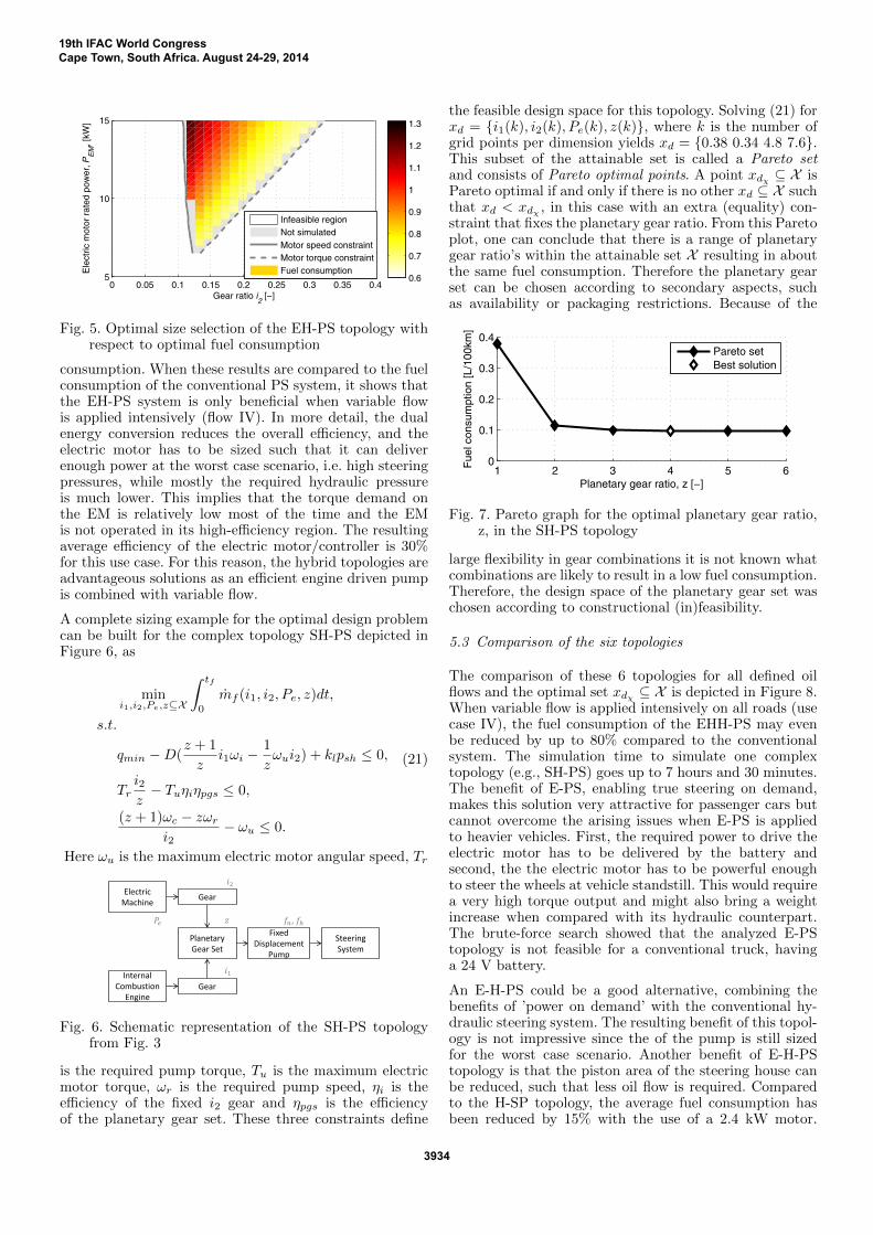
the feasible design space for this topology. Solving (21) forxd = {i1(k), i2(k), Pe(k), z(k)}, where k is the number ofgrid points per dimension yields xd = {0.38 0.34 4.8 7.6}.This subset of the attainable set is called a Pareto setand consists of Pareto optimal points. A point xdχ ⊆ X isPareto optimal if and only if there is no other xd ⊆ X suchthat xd < xdχ , in this case with an extra (equality) con-straint that fixes the planetary gear ratio. From this Paretoplot, one can conclude that there is a range of planetarygear ratio’s within the attainable set X resulting in aboutthe same fuel consumption. Therefore the planetary gearset can be chosen according to secondary aspects, suchas availability or packaging restrictions. Because of the
1 2 3 4 5 60
0.1
0.2
0.3
0.4
Planetary gear ratio, z [−]
Fue
l con
sum
ptio
n [L
/100
km]
Pareto setBest solution
Fig. 7. Pareto graph for the optimal planetary gear ratio,z, in the SH-PS topology
large flexibility in gear combinations it is not known whatcombinations are likely to result in a low fuel consumption.Therefore, the design space of the planetary gear set waschosen according to constructional (in)feasibility.
5.3 Comparison of the six topologies
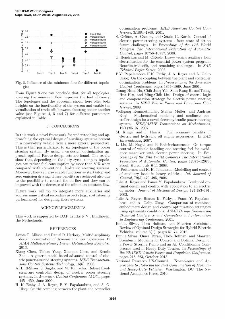
The comparison of these 6 topologies for all defined oilflows and the optimal set xdχ ⊆ X is depicted in Figure 8.When variable flow is applied intensively on all roads (usecase IV), the fuel consumption of the EHH-PS may evenbe reduced by up to 80% compared to the conventionalsystem. The simulation time to simulate one complextopology (e.g., SH-PS) goes up to 7 hours and 30 minutes.The benefit of E-PS, enabling true steering on demand,makes this solution very attractive for passenger cars butcannot overcome the arising issues when E-PS is appliedto heavier vehicles. First, the required power to drive theelectric motor has to be delivered by the battery andsecond, the the electric motor has to be powerful enoughto steer the wheels at vehicle standstill. This would requirea very high torque output and might also bring a weightincrease when compared with its hydraulic counterpart.The brute-force search showed that the analyzed E-PStopology is not feasible for a conventional truck, havinga 24 V battery.
An E-H-PS could be a good alternative, combining thebenefits of ’power on demand’ with the conventional hy-draulic steering system. The resulting benefit of this topol-ogy is not impressive since the of the pump is still sizedfor the worst case scenario. Another benefit of E-H-PStopology is that the piston area of the steering house canbe reduced, such that less oil flow is required. Comparedto the H-SP topology, the average fuel consumption hasbeen reduced by 15% with the use of a 2.4 kW motor.
19th IFAC World CongressCape Town, South Africa. August 24-29, 2014
3934
Top. 1 Top. 2 Top. 3 Top. 4 Top. 5 Top. 60
0.1
0.2
0.3
0.4
0.5
0.6
0.7
Ave
rage
fuel
con
sum
ptio
n, Φ
, [L/
100k
m]
Fixed flowVariable flow IVariable flow IIVariable flow IIIVariable flow IV
Fig. 8. Influence of the minimum flow for different topolo-gies
From Figure 8 one can conclude that, for all topologies,lowering the minimum flow improves the fuel efficiency.The topologies and the approach shown here offer bothinsights on the functionality of the system and enable thevisualisation of trade-offs between choosing one or anothervalue (see Figures 4, 5 and 7) for different parametersexplained in Table 1.
6. CONCLUSIONS
In this work a novel framework for understanding and ap-proaching the optimal design of auxiliary systems presentin a heavy-duty vehicle from a more general perspective.This is then particularized to six topologies of the powersteering system. By using a co-design optimization ap-proach optimal Pareto design sets are found. The resultsshow that, depending on the duty cycle, complex topolo-gies can reduce fuel consumption by more than 80% whencompared with conventional, hydraulic steering systems.Moreover, they can also enable functions as start/stop andzero emission driving. These benefits are achieved also dueto the possibility to control the oil flow and they can beimproved with the decrease of the minimum constant flow.
Future work will try to integrate more auxiliaries andaddress some critical secondary aspects (e.g., cost, steeringperformance) for designing these systems.
ACKNOWLEDGEMENTS
This work is supported by DAF Trucks N.V., Eindhoven,the Netherlands.
REFERENCES
James T. Allison and Daniel R. Herbery. Multidisciplinarydesign optimization of dynamic engineering systems. InAIAA Multidisciplinary Design Optimization Specialist,2013.
Xiang Chen, Tiebao Yang, Xiaoqun Chen, and KeminZhou. A generic model-based advanced control of elec-tric power-assisted steering systems. IEEE Transaction-sons Control Systems Technology, 16(6), 2008.
A.H. El-Shaer, S. Sugita, and M. Tomizuka. Robust fixed-structure controller design of electric power steeringsystems. In American Control Conference (ACC), pages445 –450, June 2009.
H. K. Fathy, J. A. Reyer, P. Y. Papalambros, and A. G.Ulsoy. On the coupling between the plant and controller
optimization problems. IEEE American Control Con-ference, 3:1864–1869, 2001.
S. Gruner, A. Gaedke, and Gerald G. Karch. Control ofelectric power steering systems - from state of art tofuture challenges. In Proceedings of the 17th WorldCongress The International Federation of AutomaticControl, pages 10756–10757, 2008.
T. Hendricks and M. OKeefe. Heavy vehicle auxiliary loadelectrification for the essential power system program:Benefits,tradeoffs, and remaining challenges. In SAETehnical Paper Series, 2002.
P.Y. Papalambros H.K. Fathy, J. A. Reyer and A. GalipUlsog. On the coupling between the plant and controlleroptimization problems. In Proceedings of the AmericanControl Conference, pages 1864–1869, June 2001.
Tsung-Hsien Hu, Chih-Jung Yeh, Shih-Rung Ho andTsungHua Hsu, and Ming-Chih Lin. Design of control logicand compensation strategy for electric power steeringsystems. In IEEE Vehicle Power and Propulsion Con-ference, 2008.
Wolfgang Kemmetmuller, Steffen Muller, and AndreasKugi. Mathematical modeling and nonlinear con-troller design for a novel electrohydraulic power-steeringsystem. IEEE/ASME Transactions on Mechatronics,12(1):85–97, 2007.
M. Kluger and J. Harris. Fuel economy benefits ofelectric and hydraulic off engine accessories. In SAEInternational, 2007.
L. Liu, M. Nagai, and P. Raksincharoensak. On torquecontrol of vehicle handling and steering feel for avoid-ance maneuver with electric power steering. In Pro-ceedings of the 17th World Congress The InternationalFederation of Automatic Control, pages 12073–12078,Seoul, Korea, July 6-11 2008.
N. Pettersson and K. H. Johansson. Modelling and controlof auxiliary loads in heavy vehicles. Int. Journal ofControl, 79(5):479–495, 2006.
Julie A. Reyer and Panos Y. Papalambros. Combined op-timal design and control with application to an electricdc motor. Journal of Mechanical Design, 124:183–191,2002.
Julie A. Reyer, Hosam K. Fathy, , Panos Y. Papalam-bros, and A. Galip Ulsoy. Comparison of combinedembodiment design and control optimization strategiesusing optimality conditions. ASME Design EngineeringTechnical Conference and Computers and Informationin Engineering Conference, 2001.
Emilia Silvas, Theo Hofman, and Maarten Steinbuch.Review of Optimal Design Strategies for Hybrid ElectricVehicles. volume 3(1), pages 57–74, 2012.
Emilia Silvas, Omer Turan, Theo Hofman, and MaartenSteinbuch. Modeling for Control and Optimal Design ofa Power Steering Pump and an Air Conditioning Com-pressor used in Heavy Duty Trucks. In Proceedings ofthe 9th IEEE Vehicle Power and Propulsion Conference,pages 218–223, October 2013.
National Research US-Council. Technologies and Ap-proaches to Reducing the Fuel Consumption of Medium-and Heavy-Duty Vehicles. Washington, DC: The Na-tional Academies Press, 2010.
19th IFAC World CongressCape Town, South Africa. August 24-29, 2014
3935