Embed Size (px)
Citation preview
Abstract—This work presents the design of pelletizing
machine for the production of pellets from a mixture either in
its powder or molten form. This idea came up during the
process of producing pellets for the purpose of strength
measurements of powder agglomerates/pellets for good
handling of powder materials for usage and during
transportation. The machine consist a mixer. This machine is
mainly found in production industries, railway/coal
corporations and steel industries.
Index Terms—Pelletizing machine, pellets, agglomerates.
I. INTRODUCTION OF DESIGN
Palletizing machine is specialized equipment. It is used
for pelletizing of powder materials into pellets.
It is original and peculiar with large scale disc-pellet
machine and designed on the basis of the large scale disc-
pellet machine that is used in industries like iron and steel
industry, chemical industry, pharmaceutical industry,
cement industry, ceramics industry, railway corporations,
seen in metallurgical workshops and some related industries.
This machine adapts to pelletizing many kinds of powder
material provided it is mixed with a particular solvent.
The rotation disk is automatic and raw material collection
and granulating capacity will be higher. The disc balling
machine is used in the balling granular used to make damp
granule into antique pellets. [1]–[3]. It is equally used in the
palletizing and alkaline leaching of powdery low grade zinc
oxide ores [4]. It is also used in the mines.
Disc balling granulator is suitable for mixing material
pelletizing equipment with nutrient [5]. It has the following
advantages:
1) High balling rate
2) Big roundness intensity of particles
3) Visual operation and easy for maintenance.
They are of different kinds and forms ranging from its
sizes, shapes, method of operation (manual or automatic),
capacity, function, etc.
A. Types of Pelletizing Machine
1) Pelletizing machine (Balling disc): Balling disc machine
is mainly used for production of balls and agglomerates
pellets.
2) Floating feed pellet machine: This type of pelletizing
machine is used for production of feed for animals.
3) Wood pellets machine: This type of palletizing machine
is used for making pellets of wood, plastics etc.
4) Biomass pellet machine: This type of palletizing
Manuscript received October 22, 2013; revised April 19, 2014.
K. O. Ikebudu and Swift O. N. K. are with the Anambra State University, Uli, Nigeria (e-mail: [email protected]).
Chukwumuanya E. O. and Nwokeocha Toochukwu are with the
Nnamdi Azikiwe University, Awka, Anambra State, Nigeri.
machine is used for producing pellets from biomass.
B. Pelletization
Pelletization [6] is the unit operation of producing larger
bodies from fine powders so as to alleviate many of the
problems associated with fine particulates, for example,
some of the benefits provided by pelletizing coal include;
1) Improved fugitive dust control
2) Decrease in transportation costs and losses
3) Reduced risk of spontaneous usage
Only partial understandings of the fundamentals of
powder material pillarization exist in this project. In this
project, we attempted to design palletizing machine for
understanding of engineering material handling.
II. DESIGN SIGNIFICANCE
Poor handling of coal has affected the iron and steel
industries, Railway Corporation and coal industries.
However, the contemporary palletizing machine is so
expensive that some industries in Nigeria cannot afford the
price. With the design of pelletizing machine to form pellets
as the case maybe, for good handling of powder material,
there will be improved fugitive dust control, decrease in
transportation costs and losses, reduction in the risk of coal
freezing and lowered risk of spontaneous combustion/ usage
[6].
III. DESIGN ANALYSIS
Considering the single phase induction motor with a
speed of 400rpm, having a power of 1800kw, the diameter
of the shaft from the motor is 20mm.
To calculate the angular velocity of the motor;
W=2πN÷60= (2×3.142×400) ÷ 60
W=41.89/sec
To find the actual torque of the motor
Torque (T) = P/W
where
P=1800×1000
W=41.89
T=1800×10³×1000/41.89=42969.7 KN/m
Again to calculate for the torque transmitted
T=P × 60/2 Πn
T=1800 × 1000 × 60/2π×400
T=108000000/2513.3
T=42971.835 N/m
IV. MATERIAL SELECTION
One of the basic factors that affect the choice of a project
is the availability of materials, selection of materials, and
Design of Pelletizing Machine (Balling Disc)
K. O. Ikebudu, Chukwumuanya E. O., Swift O. N. K., and Nwokeocha Toochukwu
International Journal of Materials, Mechanics and Manufacturing, Vol. 3, No. 1, February 2015
9DOI: 10.7763/IJMMM.2015.V3.156
the cost of the materials for the design or fabrication of the
project. The materials selection for the design function
depends on the following;
The availability of these materials in our local markets.
The strength of these materials
The cost of these materials
The possession of simple mode of the operation
The appearance of these materials
The ability of these materials to serve the purpose for
which the project is intent to be designed.
A. Materials
Metallic gears
Electric motors (single phase)
Angle iron
Stainless Disc (25 cm)
Fasteners (bolts and nuts)
Washers
Shaft
Vibration Pad
Cream hardeners
Citizen gloss paint (army green)
Hand grinding machine
Hand drilling machine
Welding machine
Sand paper
Chisel
Hammer
Scriber
Try square
Bench vice
Hack saw
Flat file
Hand Glove
Welding goggle
V. DESIGN OF KEY
The key [7] is made of mild steel used in the locking of
the gear to the motor shaft. It is inserted between the shaft
and the hub of the gear acting as the pulley to connect both
the gear and the shaft together in other to prevent relative
motion between them. It is also inserted parallel to the axis
of the shaft. The name of the key used in this design is
square sunk key.
Mathematically,
W = T = D/4
where,
W = width of the key
T = Thickness of the key
D = Diameter of the key
D = 20mm
W = T = 20/4 = 5mm
NB: A key way which is a slot or recess in the shaft from
the motor and the hub of the gear acting as the pulley to
accommodate the key made. Basically keys are used as
temporary fasteners and subjected to consider crushing and
shearing stresses.
Also note that during the design of the key, forces due to
fit of the key where neglected and it was assumed that the
distribution of forces along the length of the key is uniform.
Now owing to the fact that
L × W × T × d/2 = L × t/2 × бc × d/2
w/t = бc/2T
where
W = width of the key
T = Thickness of the key
бc = crushing stress of the key
ĩ = Shearing stress of the key
Therefore the key used in this design is equally strong in
shearing and crushing. Know that the key material and shaft
material are the same.
To find the speed of the driven N2
From T2 = N 1T 1/N2
N2= N1T1 /T2
where,
T1=no of teeth of drivers = 24
T2=no of teeth of driven=24
1= speed of driver =400
N2= speed of driven=200
Mean speed = 400 + 200/2 = 300rpm
N=300rpm
N2 = 400 × 24/24 = 400rpm
N = 300 × 24/24 = 300rpm
Therefore, if N1 =N2
T1 = T2
This means that gears transmits equal amount of speed.
The name of the gear is spur gear, with 50mmdiameter as
pitch circle.
Dp = mTp
To find the modulus
50/24 =m
M=2.08
A. Design of Step Turned Shaft
The shaft used in this design is called a transmission shaft.
Now assuming the allowable shear stress as 42mpa the line
shaft is rotating at 400rpm and transmitting 18kw.
To find the diameter of the shaft
T = p × 60/2πN = 18 × 10³ × 60/2π × 400
=429.69 = 430 N-m or
= 430 × 10³ N-mm
But T = π/16 × τ × d³
430 × 10³= π/16 × 42 × d
430 × 10³/16=π 42d³
203.65 = d
d = 5.8mm
NB: we assumed 20mm diameter of the shaft because of
its rigidity and loading.
VI. METHODOLOGY
A. Marking out
The first stage of this fabrication is the marking out of the
required dimensions of the sheet metal and the angle iron
together with the square iron bars [8].
B. Cutting process
The second stage after the required dimensions is marked
International Journal of Materials, Mechanics and Manufacturing, Vol. 3, No. 1, February 2015
10
out the cutting out of the required length from the main
material will take place. The cutting out is done on the vice
with the aid of a hacksaw.
C. Welding Process
After the first two processes is carried out, the materials
are joined together by means of the joining process called
“WELDING”. This involves the welding of the various
parts of the frame together using the electric arc welding
process.
D. Boring Process
After the welding process, holes are bored into the frame
to accommodate the bolts and nuts that will be used to
fasten the machine parts together.
E. Coupling Process
This comprises the coupling of the various parts of the
machine which include the induction motor, the stainless
pan, the shaft, the gear train.
F. Filler Process
This involves the process of filling the various holes and
uneven surfaces on the machine with a filler material which
is strengthened by a cream hardener.
G. Painting Process
This is the final process of the work which involves the
painting of the machine surface with oil base paint. The
painting is done with the aid of a spray-painting machine.
VII. DESIGN ASSEMBLY OF PELLETIZING MACHINE
The marking out process, cutting process, welding
process, Boring process, coupling process, filling process,
Painting processes will be done with the required precision.
The joint parts of the Machine will be fastened with the
appropriate fasteners. During the assembling, a damper
rubber will be used to seal through the edges of the stainless
pot including the cover to avoid material loss when the
machine is functioning. Due to vibration by the electric
motor inside the machine when at work or in operation, the
use of a vibration pad will be introduced at the base to
control and reduce the vibration effect of the machine. At
the end of the assembling operation metal casing will be
formed to encapsulate the machine itself to avoid the
exposure of the skeletal parts. This metal casing will also be
used to make the machine fanciful and presentable. The
metal casing will provide support and stability to the
machine which will help the machine to stand on its own
without falling to any direction. This enclosure will be
perforated to aid cooling of the electric motor.
VIII. SCHEMATIC REPRESENTATION OF THE PELLETIZING
MACHINE
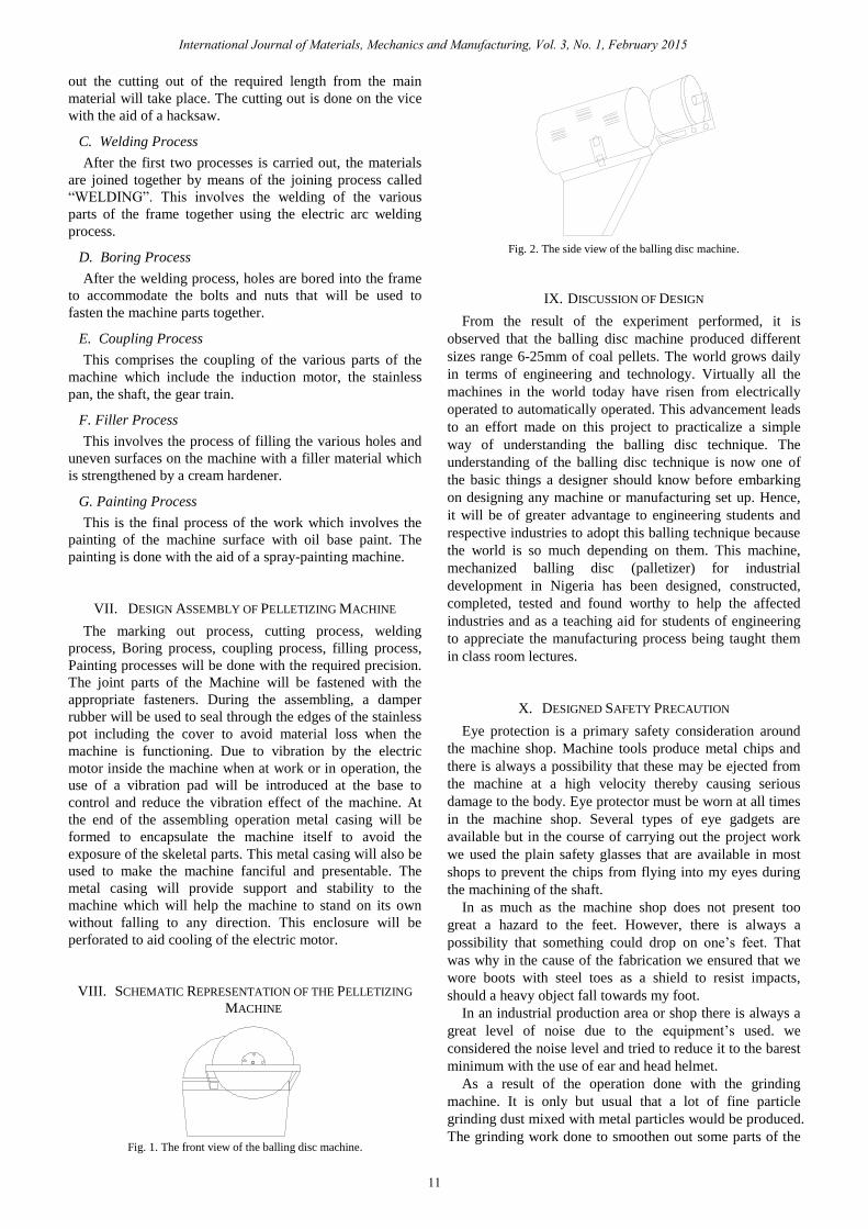
Fig. 1. The front view of the balling disc machine.
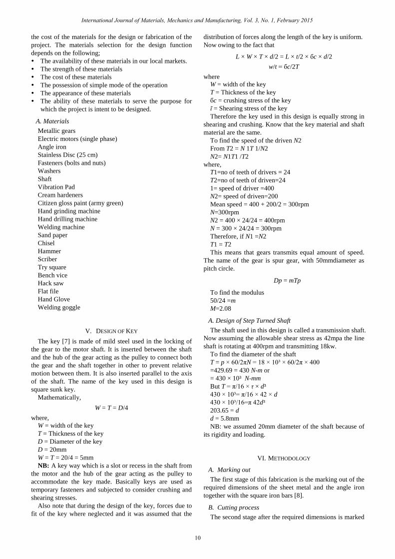
Fig. 2. The side view of the balling disc machine.
IX. DISCUSSION OF DESIGN
From the result of the experiment performed, it is
observed that the balling disc machine produced different
sizes range 6-25mm of coal pellets. The world grows daily
in terms of engineering and technology. Virtually all the
machines in the world today have risen from electrically
operated to automatically operated. This advancement leads
to an effort made on this project to practicalize a simple
way of understanding the balling disc technique. The
understanding of the balling disc technique is now one of
the basic things a designer should know before embarking
on designing any machine or manufacturing set up. Hence,
it will be of greater advantage to engineering students and
respective industries to adopt this balling technique because
the world is so much depending on them. This machine,
mechanized balling disc (palletizer) for industrial
development in Nigeria has been designed, constructed,
completed, tested and found worthy to help the affected
industries and as a teaching aid for students of engineering
to appreciate the manufacturing process being taught them
in class room lectures.
X. DESIGNED SAFETY PRECAUTION
Eye protection is a primary safety consideration around
the machine shop. Machine tools produce metal chips and
there is always a possibility that these may be ejected from
the machine at a high velocity thereby causing serious
damage to the body. Eye protector must be worn at all times
in the machine shop. Several types of eye gadgets are
available but in the course of carrying out the project work
we used the plain safety glasses that are available in most
shops to prevent the chips from flying into my eyes during
the machining of the shaft.
In as much as the machine shop does not present too
great a hazard to the feet. However, there is always a
possibility that something could drop on one’s feet. That
was why in the cause of the fabrication we ensured that we
wore boots with steel toes as a shield to resist impacts,
should a heavy object fall towards my foot.
In an industrial production area or shop there is always a
great level of noise due to the equipment’s used. we
considered the noise level and tried to reduce it to the barest
minimum with the use of ear and head helmet.
As a result of the operation done with the grinding
machine. It is only but usual that a lot of fine particle
grinding dust mixed with metal particles would be produced.
The grinding work done to smoothen out some parts of the
International Journal of Materials, Mechanics and Manufacturing, Vol. 3, No. 1, February 2015
11
machine was done in open area where there was rapid flow
of air.
In the cause of welding we ensured that we wore
coveralls to protect skin from the fire sparks coming out due
to welding.
XI. DESIGNED MAINTENANCE
It is a well-known fact and an act of responsibility to
know how to care and maintain machine. Without this
maintenance culture amongst us, there would be nonparallel
waste of resources in order to procure new machines and
whole lots of recyclable waste. In the fabrication of the
balling disc machine, the care and maintenance of the
machine was highly considered and an easy maintenance
culture was included.
The stainless pan was provided with holes in the base and
attached to the shaft with bolts and nuts to ensure easy
removal for cleaning. Various types and sizes of bolts, nuts
and washers were used extensively throughout the system to
ensure easy assembling and disassembling and to facilitate
easy cleaning.
In the care of the gears, a reasonable amount of grease
should be applied to the gear train so as to facilitate easy
movement of the gear.
The wire connected to the electric motor to the power
supply should be checked often to see if there is an internal
snap in the wire or if the wire is about to cut.
The frame of the machine should be dusted frequently
and should not be allowed to be exposed to water. The
machine should not be used as an alternative to a seat. The
machine should never be overloaded.
XII. DESIGNED RECOMMENDATION
This machine has been designed, fabricated and tested. It
is working effectively and conveniently. The project is of
benefit and as a teaching aid.
Consequently, from this benefit, the machine is
recommended to manufacturers for usage. More importantly,
this machine is recommended to scholars for further
research and improvement.
XIII. CONCLUSION
The result of the balling disk machine showed good
formation of agglomerates balls / pellets diameter from 6 -
25mm. Basically, it is seen mostly in industries like iron and
steel industry, chemical industry, pharmaceutical industry,
cement industry, ceramics industry, railway corporations,
seen in metallurgical workshops and some related industries.
REFERENCES
[1] Drying product. [Online]. Available: http://www.busytrad.com/
[2] Drying product. [Online]. Available:
http://www.chinadrying/products/gpc_15.php [3] Drying product. [Online]. Available:
http://www.khm.com.cn/english/qita/manufacture/qita_cq.php
[4] Science Direct. [Online]. Available: http://www.sciencedirect.com [5] Disc balling granulator. [Online]. Available:
http://www.jderusher.com/product/ypzlg.htm
[6] K. V. S. Sastry, “Reporting period,” University of California,
College of Engineering,” Department of Materials Science and
Mineral Engineering, Berkeley, CA 94720.
[7] R. S Khurmi and J. K Gupta, Machine Design, Eurasia Publishing House, 2005
[8] Z. Marcinak, J. L. Duncan, and S. J Hu, Mechanics of Sheet Metal
Forming, 2nd edition, ScienceDirect, 2002
K. O. Ikebudu is working as a lecturer in the Anambra State University,
Uli, Nigeria. He was born in Nigeria in the year 1981. He has bagged his B.Eng, M.Eng and presently a Ph.D candidate. His research interest is
focused on design and production engineering.
E. O. Chukwumuanya is working as a lecturer in the Nnamdi Azikiwe
University, Awka, Anambra State, Nigeria. He was born in Nigeria. He has bagged his B.Eng, M.Eng and presently a Ph.D candidate. His research
interest is focused on industrial production engineering.
O. N. K. Swift is working as a lecturer in the Anambra State University,
Uli Campus, Anambra State, Nigeria. He was born in Nigeria. He has bagged his B.Sc, M.Eng and presently a Ph.D candidate. His research
interest is focused on industrial manugacturing engineering.
Nwokeocha Toochukwu is working as a technologist in the Nnamdi
Azikiwe University, Nigeria. He was born in Nigeria. He has bagged his B.Eng, and presently an M.Eng candidate. His research interest is focused
on design and industrial production engineering.
International Journal of Materials, Mechanics and Manufacturing, Vol. 3, No. 1, February 2015
12