Embed Size (px)
Citation preview

1
Design of Nonpermanent Joints (Chapter 8)

2
Chapter 8 - Topics

3
Threaded Fasteners - Introduction
Budynas, p. 396
“… the curiosity of any person
interested in mechanical
engineering naturally results in the
acquisition of a good background
knowledge of fastening methods.”
“Contrary to first impressions, the
subject is one of the most
interesting in the entire field of
mechanical design.”
4
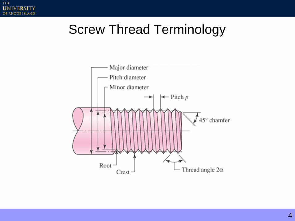
Screw Thread Terminology
5
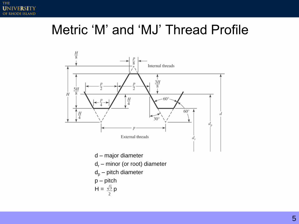
Metric ‘M’ and ‘MJ’ Thread Profile
d – major diameter
dr – minor (or root) diameter
dp – pitch diameter
p – pitch
H = p2
3
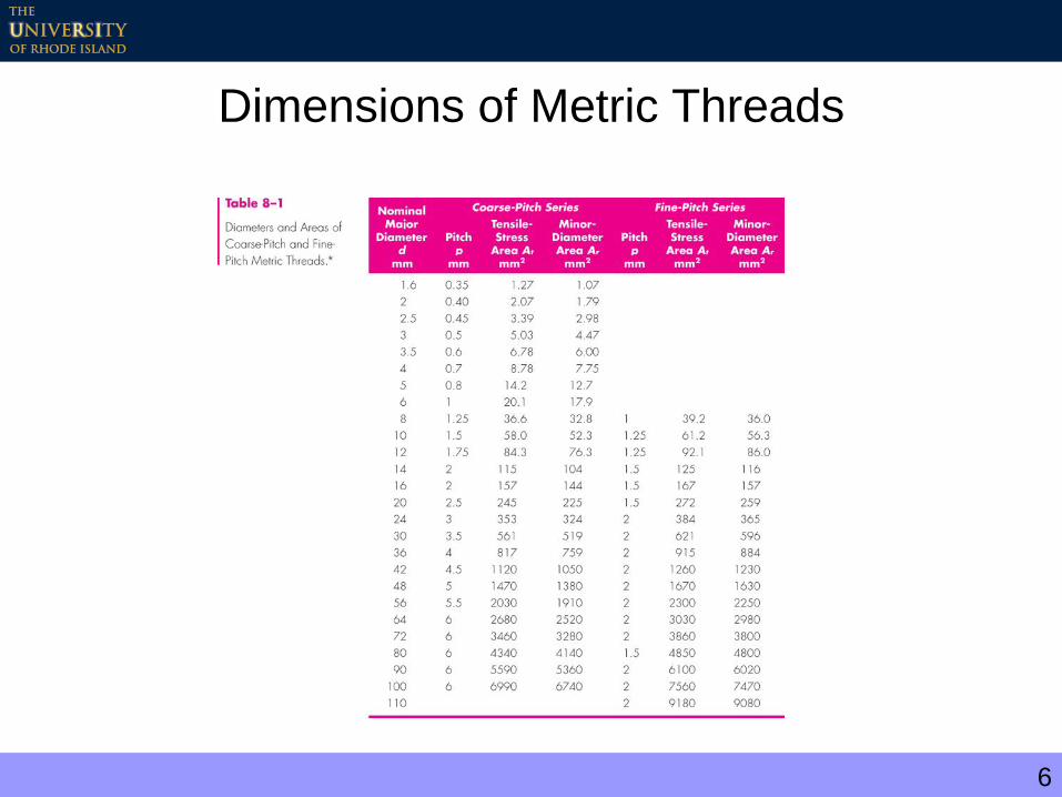
6
Dimensions of Metric Threads

7
Dimensions of UNC and UNF Threads

8
Square and ACME Threads
9
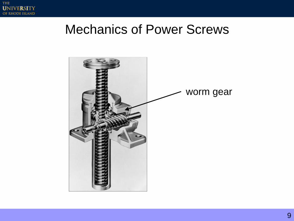
Mechanics of Power Screws
worm gear
10
Mechanics of Power Screws
Objectives:
– Determine relation between applied torque
and axial load
– Consider both raising and lowering the load
– Compute stresses at the thread root
11
Recall from Elementary Mechanics
Static equilibrium:
0
0
M
F
12
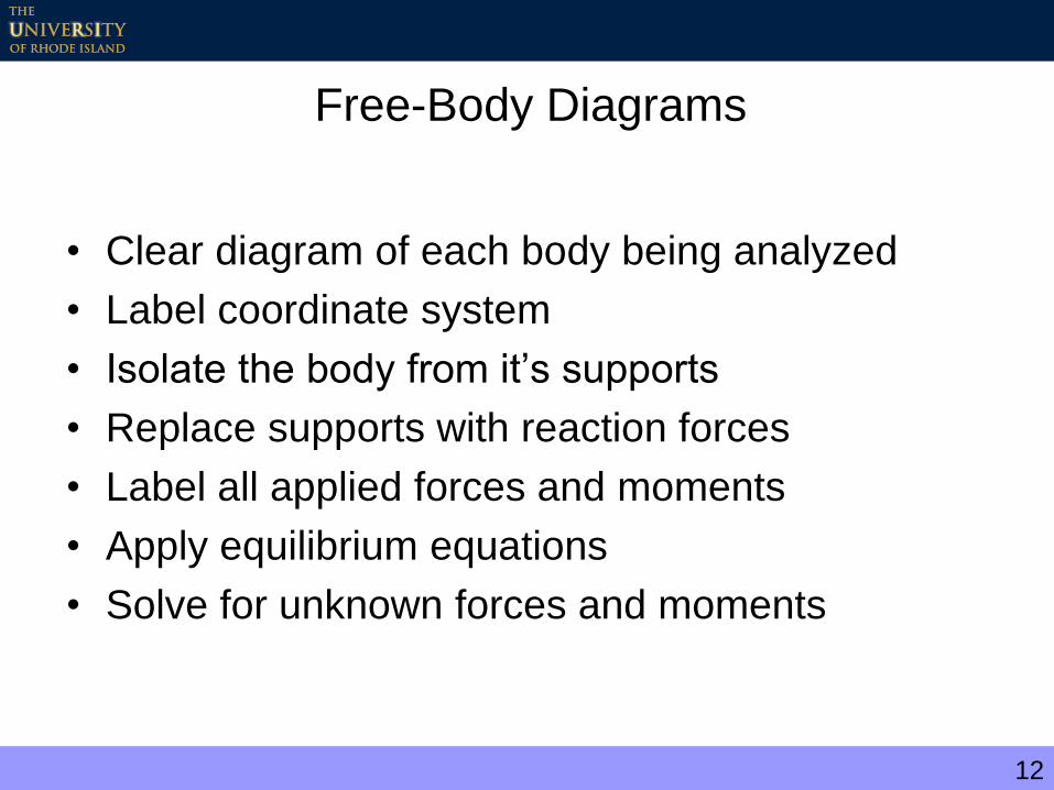
Free-Body Diagrams
• Clear diagram of each body being analyzed
• Label coordinate system
• Isolate the body from it’s supports
• Replace supports with reaction forces
• Label all applied forces and moments
• Apply equilibrium equations
• Solve for unknown forces and moments
13
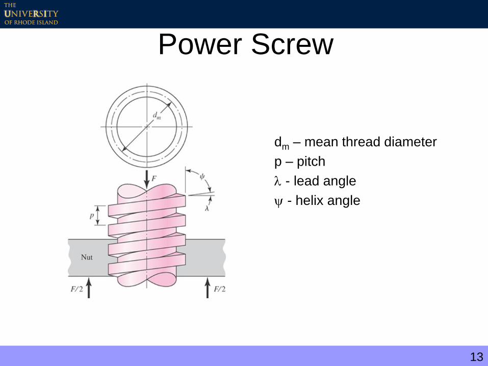
Power Screw
dm – mean thread diameter
p – pitch
- lead angle
- helix angle
14
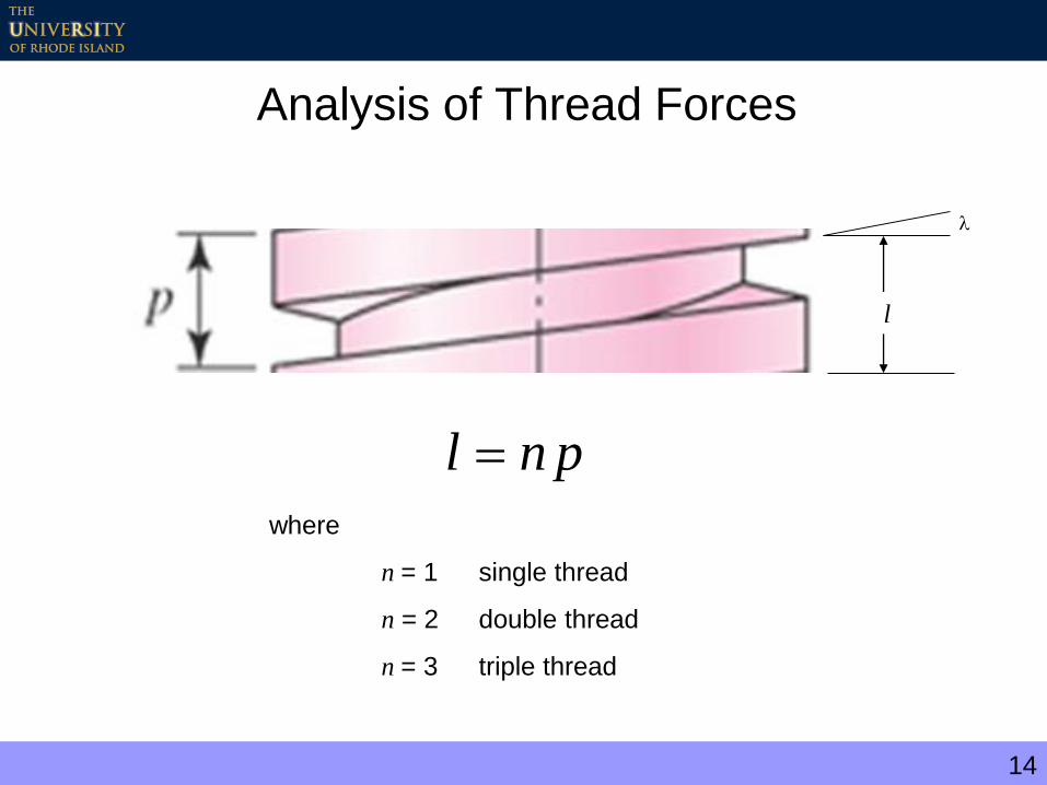
Analysis of Thread Forces
pnl
l
where
n = 1 single thread
n = 2 double thread
n = 3 triple thread

15
Free Body Diagrams
Raising the Load Lowering the Load
PR, PL – net force due to applied torque
f - friction coefficient
N - normal force
16
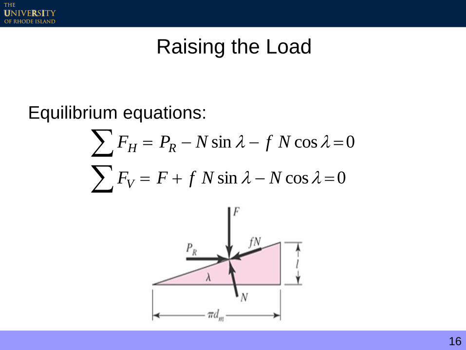
Raising the Load
Equilibrium equations:
0cossin
0cossin
NNfFF
NfNPF
V
RH
17
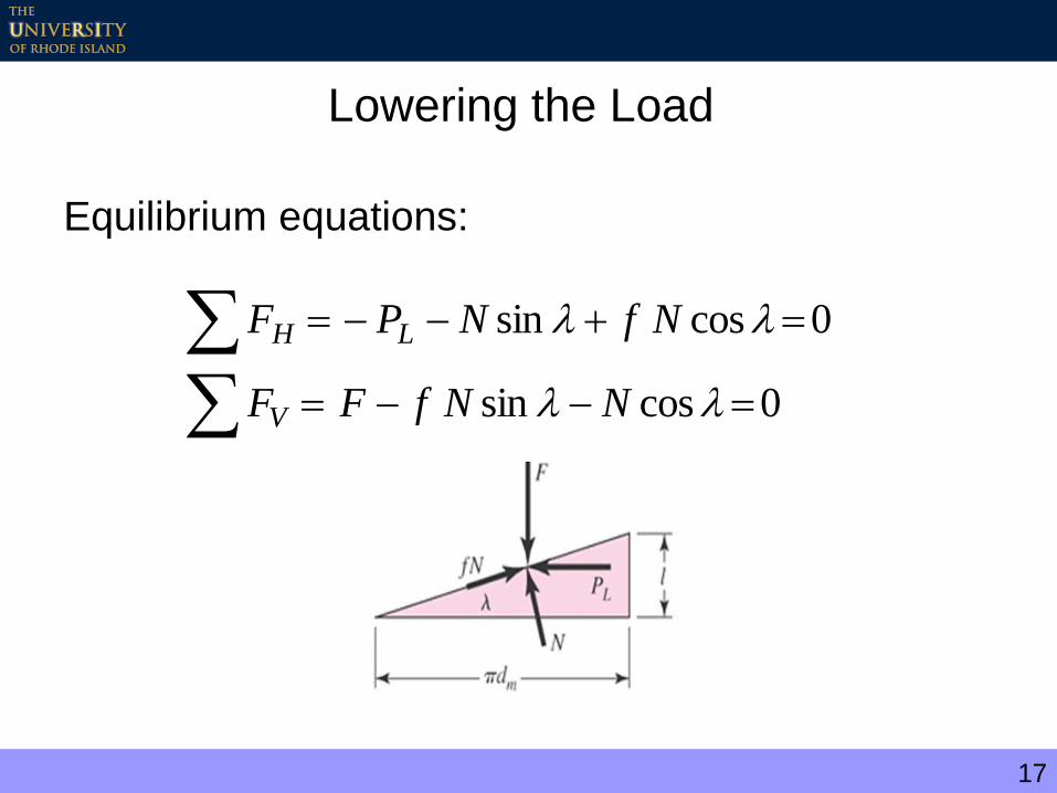
Lowering the Load
Equilibrium equations:
0cossin
0cossin
NNfFF
NfNPF
V
LH
18
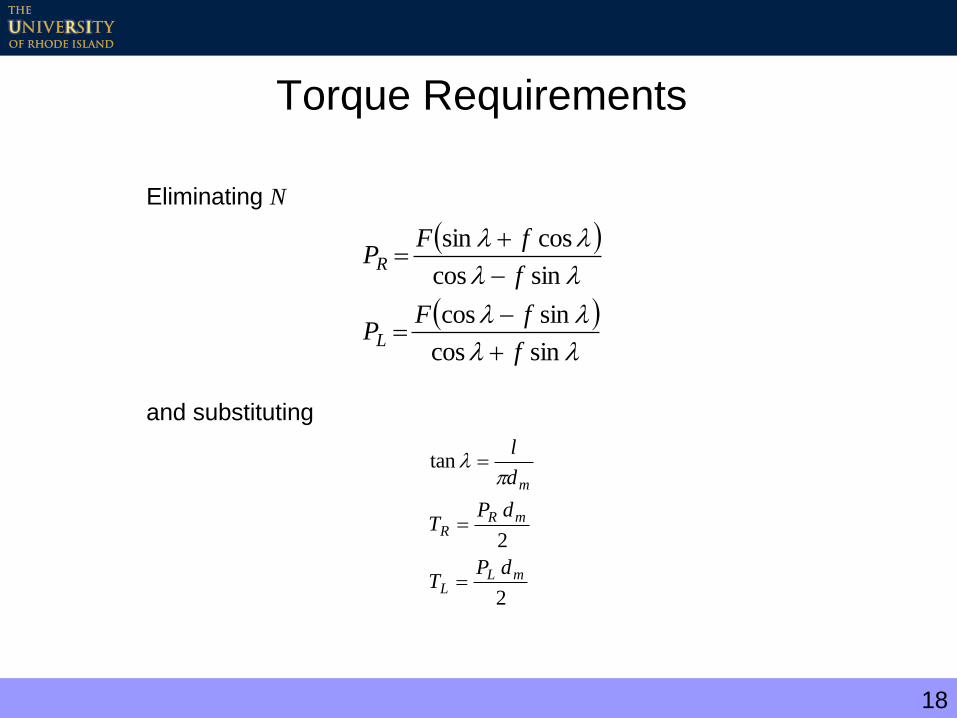
Torque Requirements
sincos
sincos
sincos
cossin
f
fFP
f
fFP
L
R
Eliminating N
and substituting
2
2
tan
mLL
mRR
m
dPT
dPT
d
l
19
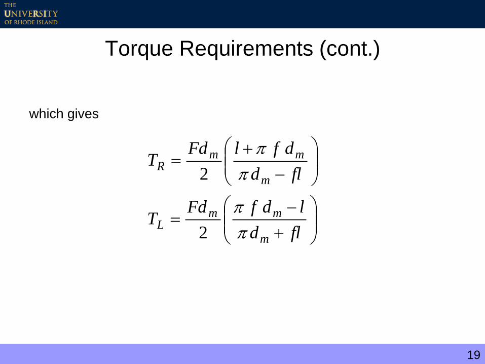
Torque Requirements (cont.)
which gives
fld
ldfFdT
fld
dflFdT
m
mmL
m
mmR
2
2

20
Effect of Friction – Raising the Load
fld
dflFdT
m
mmR
2
20
FlT
RT
Te 0
if f = 0
and the efficiency, e, is given by

21
Effect of Friction (cont.)
Lowering the load:
Note, if
f dm > l
then
TL > 0
and an applied torque is needed to lower the load. For TL 0, the screw is “self-
locking.” Since l / dm = tan , the screw is self-locking if
f > tan
fld
ldfFdT
m
mmL
2

22
Power Screw Mechanics – ACME Threads
sec
sec
2 lfd
dflFdT
m
mmR
23
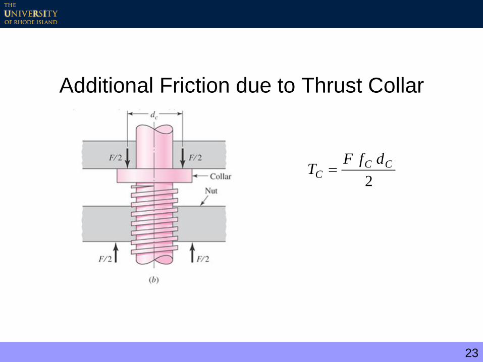
Additional Friction due to Thrust Collar
2
CCC
dfFT
24
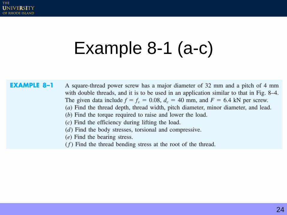
Example 8-1 (a-c)
25
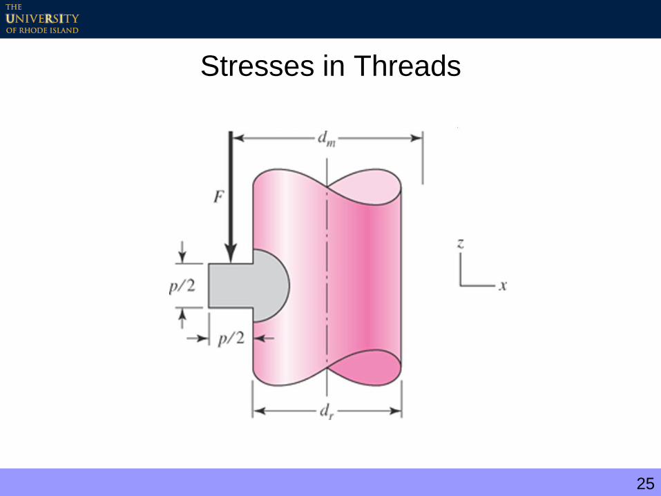
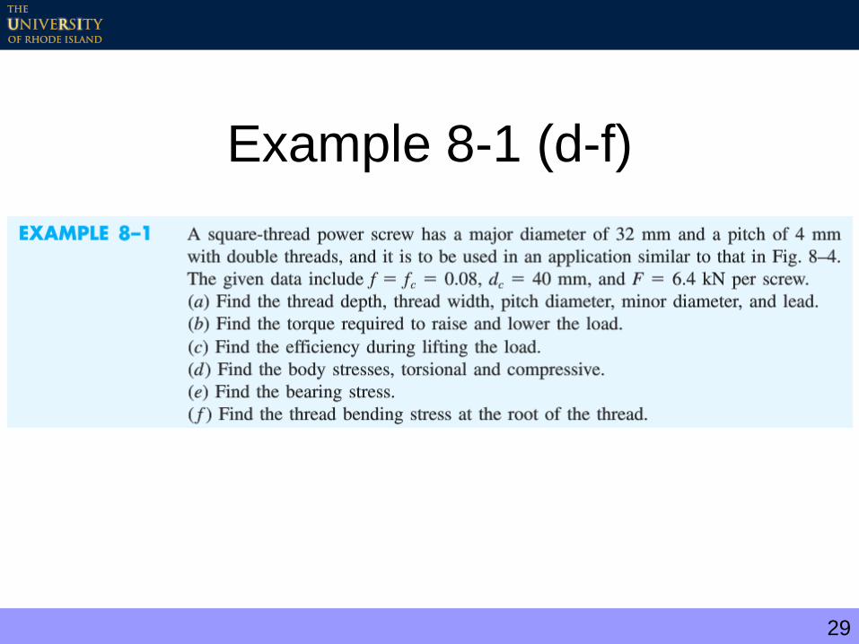
Stresses in Threads

26
Compressive axial stress
Shear stress due to torsion
2
4
rd
F
3
16
rd
T
Stresses in Body
27
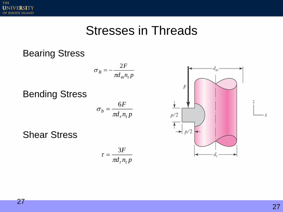
Stresses in Threads
Bearing Stress
Bending Stress
Shear Stress
pnd
F
trb
6
pnd
F
tr
3
pnd
F
tmB
2
27
28
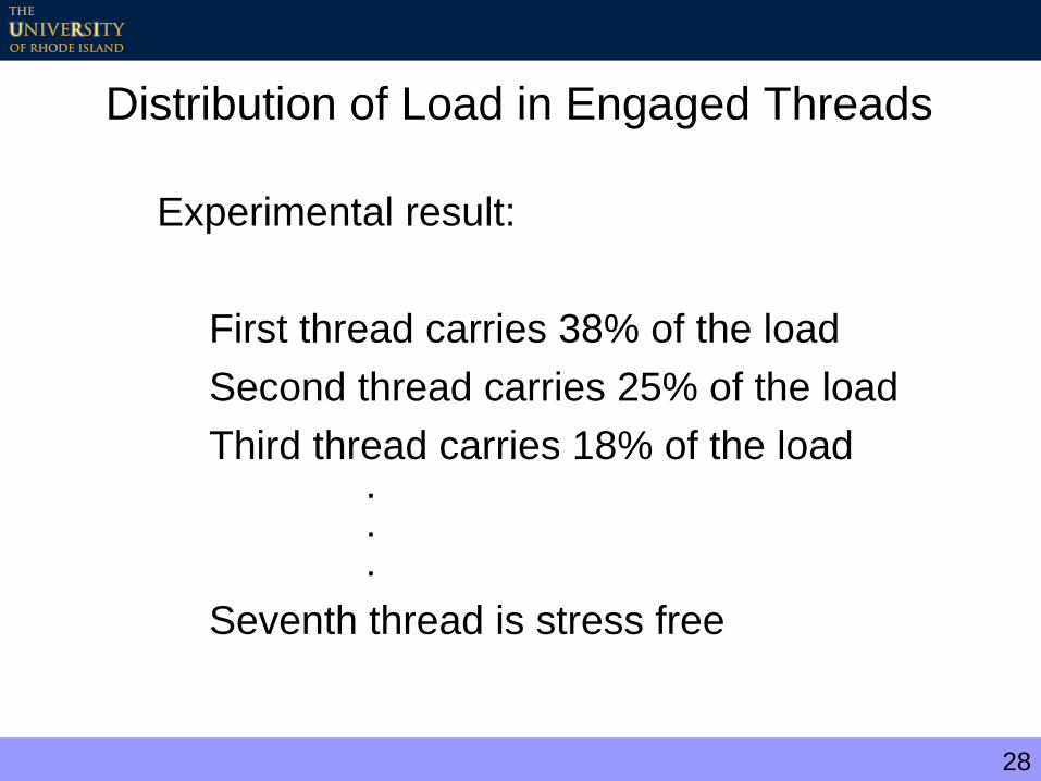
Distribution of Load in Engaged Threads
Experimental result:
First thread carries 38% of the load
Second thread carries 25% of the load
Third thread carries 18% of the load...
Seventh thread is stress free
29
Example 8-1 (d-f)
30
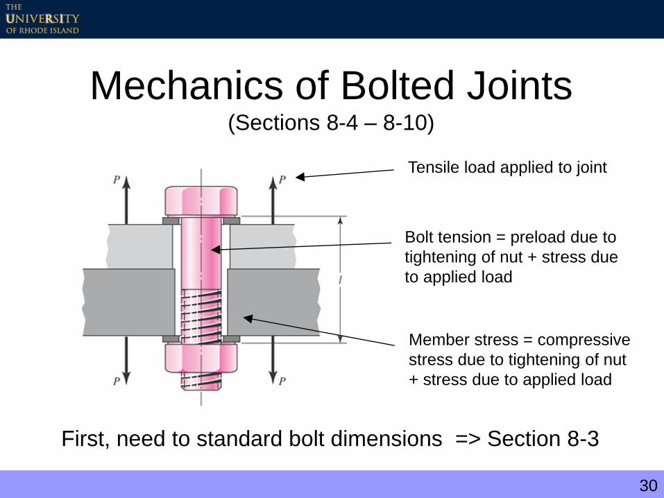
Mechanics of Bolted Joints(Sections 8-4 – 8-10)
Tensile load applied to joint
Bolt tension = preload due to
tightening of nut + stress due
to applied load
Member stress = compressive
stress due to tightening of nut
+ stress due to applied load
First, need to standard bolt dimensions => Section 8-3
31
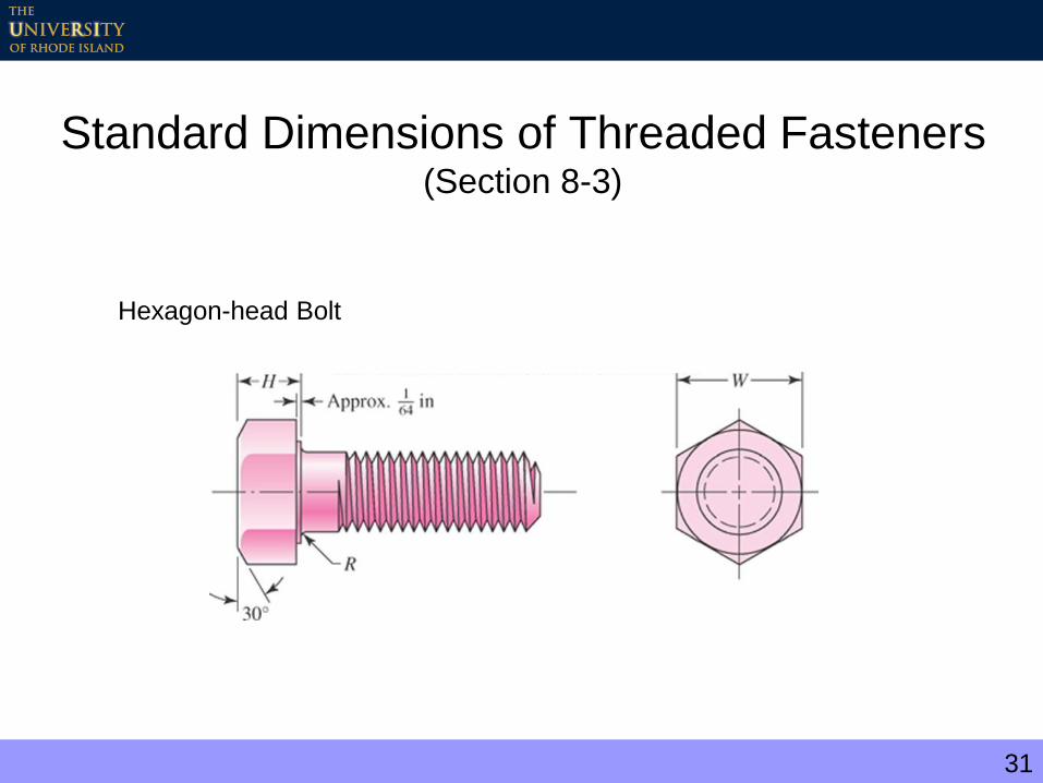
Standard Dimensions of Threaded Fasteners (Section 8-3)
Hexagon-head Bolt

32
Hexagon-head Thread Length
inLind
inLindLT
6,2
12
6,4
12
200,252
200125,122
48,125,62
Lmmd
mmLmmd
mmdmmLmmd
LTLT
Note: Ideal bolt length – one or two threads project from the nut

33
Square and Hexagonal Bolt Dimensions
(cont.)
34
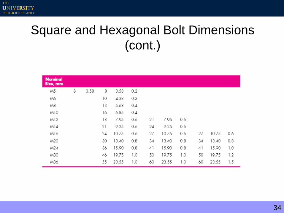
Square and Hexagonal Bolt Dimensions
(cont.)

35
Cap-screws
36
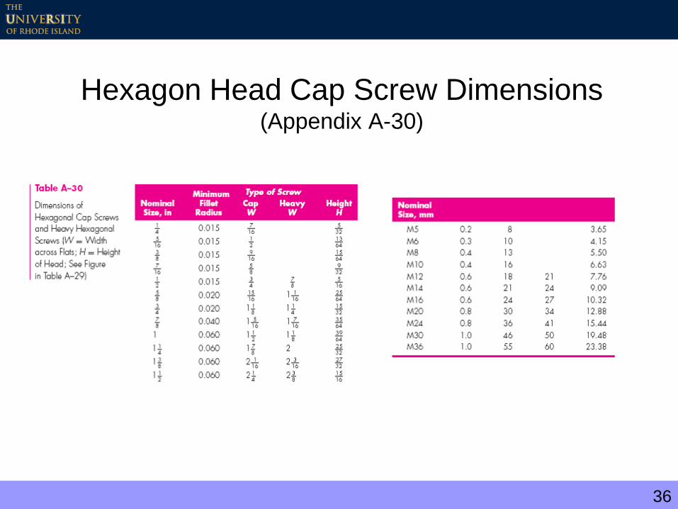
Hexagon Head Cap Screw Dimensions (Appendix A-30)

37
Machine Screws
38
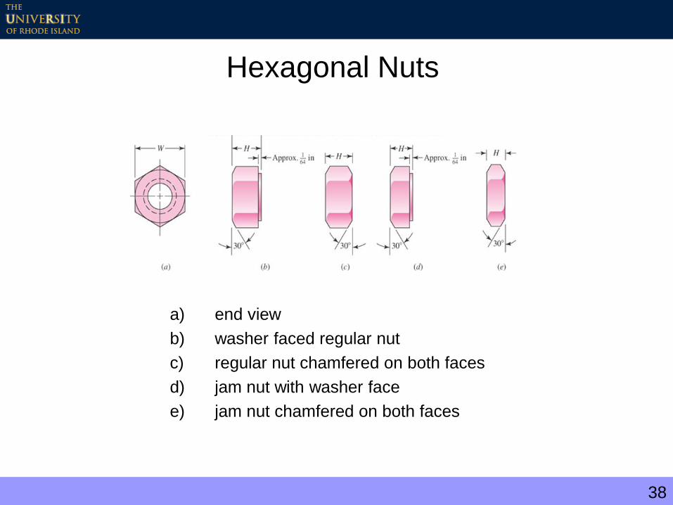
Hexagonal Nuts
a) end view
b) washer faced regular nut
c) regular nut chamfered on both faces
d) jam nut with washer face
e) jam nut chamfered on both faces

39
Hexagonal Nut Dimensions(Appendix A-31)
40
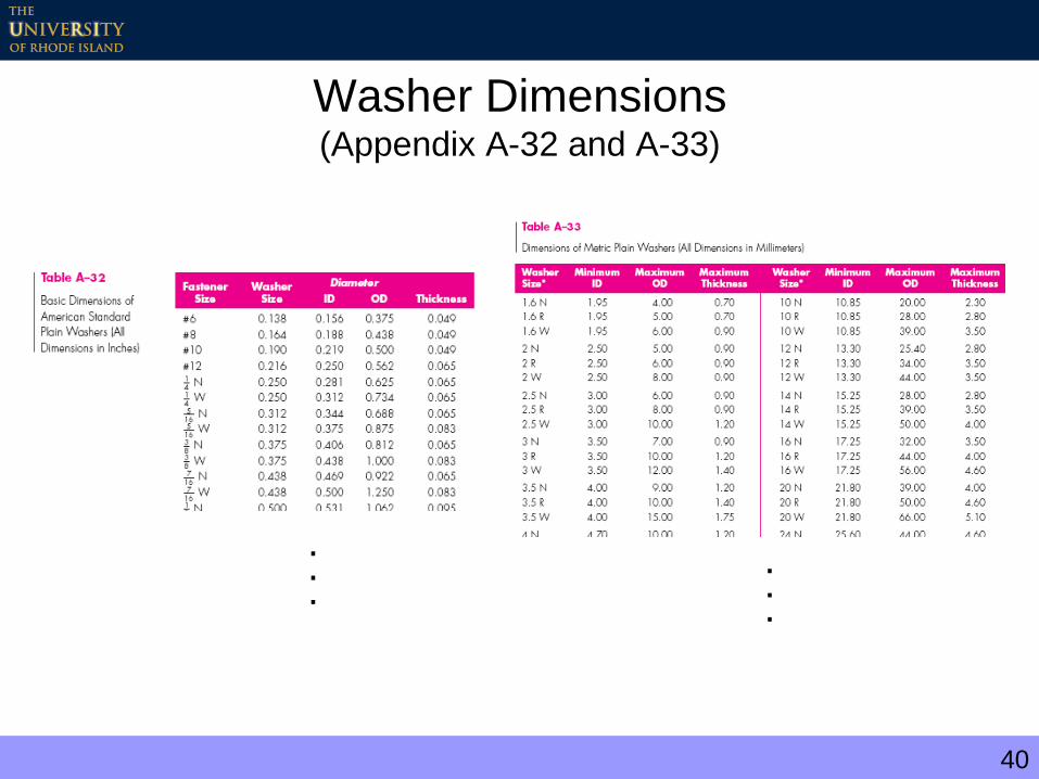
Washer Dimensions(Appendix A-32 and A-33)
.
.
....

41
Mechanics of Bolted Joints(Sections 8-4 – 8-10)
Tensile load applied to joint
Bolt tension = preload due to
tightening of nut + stress due
to applied load
Member stress = compressive
stress due to tightening of nut
+ stress due to applied load
Grip length, l

42
Alternate Bolted Connection
Effective grip
length, l’
O-ring seal

43
Fastener Stiffness(Section 8-4)
44
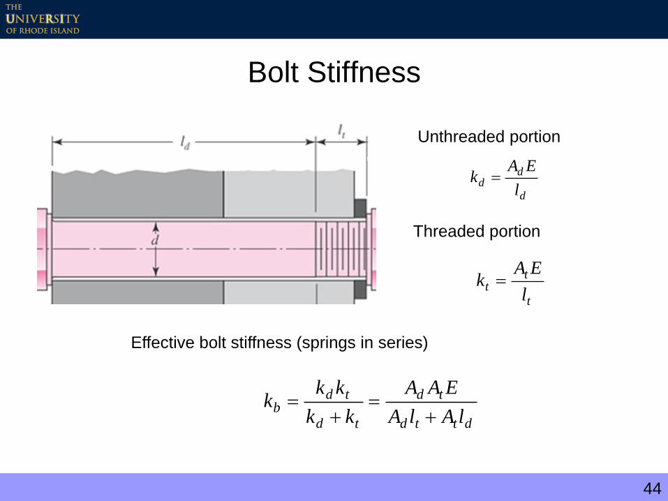
Bolt Stiffness
d
dd
l
EAk
t
tt
l
EAk
dttd
td
td
tdb
lAlA
EAA
kk
kkk
Unthreaded portion
Threaded portion
Effective bolt stiffness (springs in series)
45
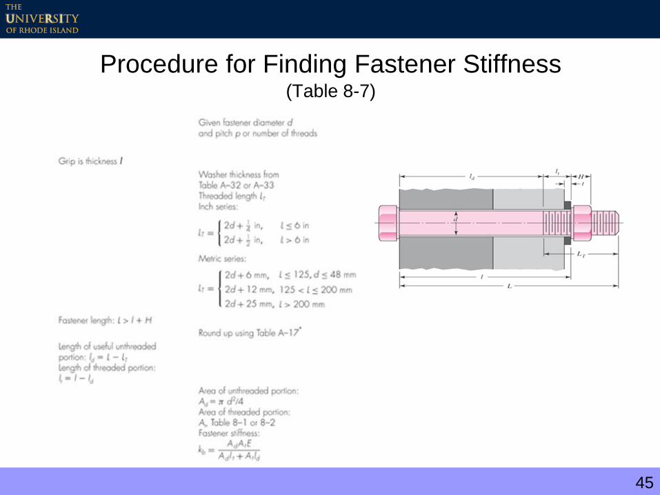
Procedure for Finding Fastener Stiffness(Table 8-7)

46
At for threaded members - Table 8-1 (see Table 8-2 for UNC and UNF)

47
Procedure for Finding Fastener Stiffness(cont.)

48
Member Stiffness(Section 8-5)
For multiple members, treat as springs in series
If one of the members is a gasket with low stiffness
im kkkkk
1...
1111
321
gasketm kk
49
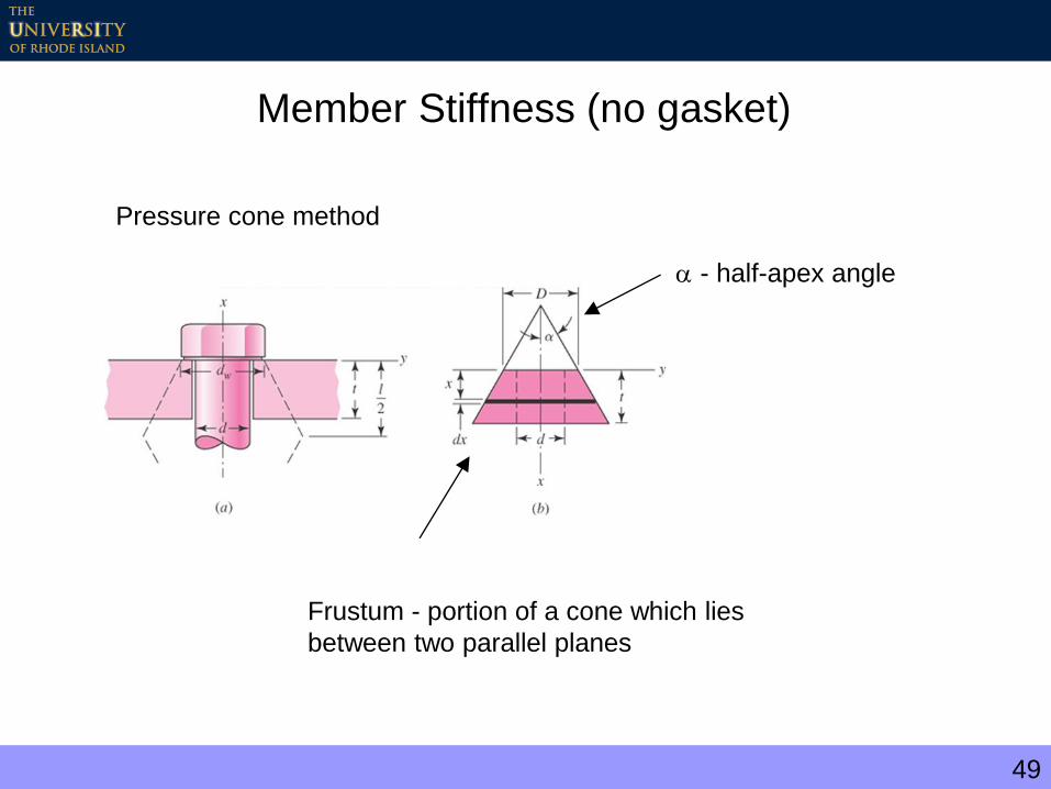
Member Stiffness (no gasket)
Pressure cone method
Frustum - portion of a cone which lies
between two parallel planes
- half-apex angle
50
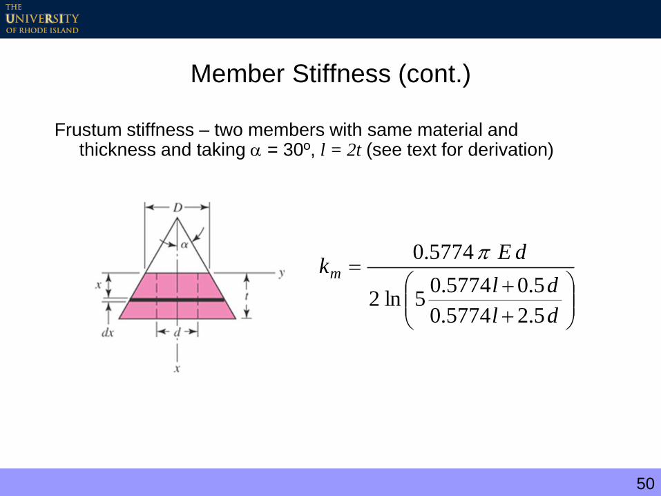
Member Stiffness (cont.)
Frustum stiffness – two members with same material and thickness and taking = 30º, l = 2t (see text for derivation)
dl
dl
dEkm
5.25774.0
5.05774.05ln2
5774.0
51
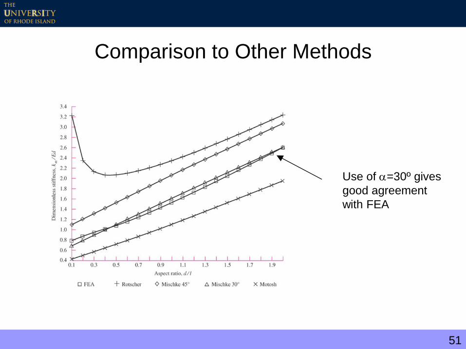
Comparison to Other Methods
Use of =30º gives
good agreement
with FEA
52
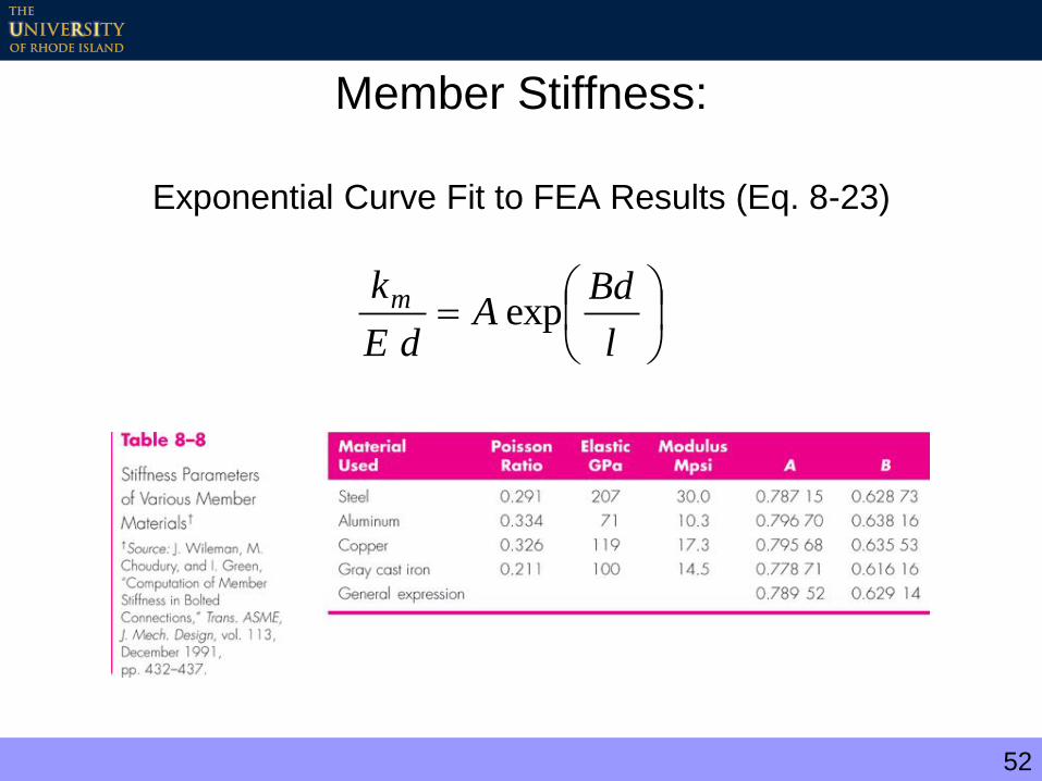
Member Stiffness:
Exponential Curve Fit to FEA Results (Eq. 8-23)
l
BdA
dE
km exp

53
Example 8-2
54
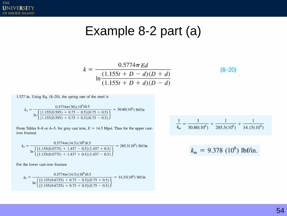
Example 8-2 part (a)

55
b) Both members are steel
c) Repeat using Eq. 8-23
Example 8-2 parts (b & c)
dl
dl
dEkm
5.25774.0
5.05774.05ln2
5774.0
l
BdA
dE
km exp

56
Example 8-2 part (d)
d) Bolt stiffness (use Table 8-7)
Table 8-7
57
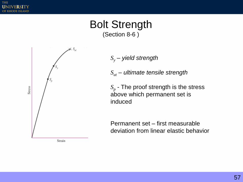
Bolt Strength(Section 8-6 )
Sy – yield strength
Sut – ultimate tensile strength
Sp - The proof strength is the stress
above which permanent set is
induced
Permanent set – first measurable
deviation from linear elastic behavior

58
Variability of Strength
Statistical measures:
Mean strength = 145.1 ksi
Standard deviation = 10.3 ksi
Minimum strength = 120 ksi
59
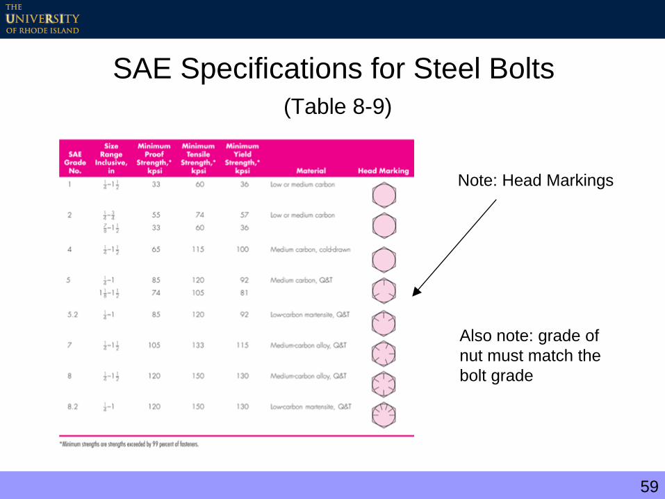
SAE Specifications for Steel Bolts
(Table 8-9)
Note: Head Markings
Also note: grade of
nut must match the
bolt grade
60
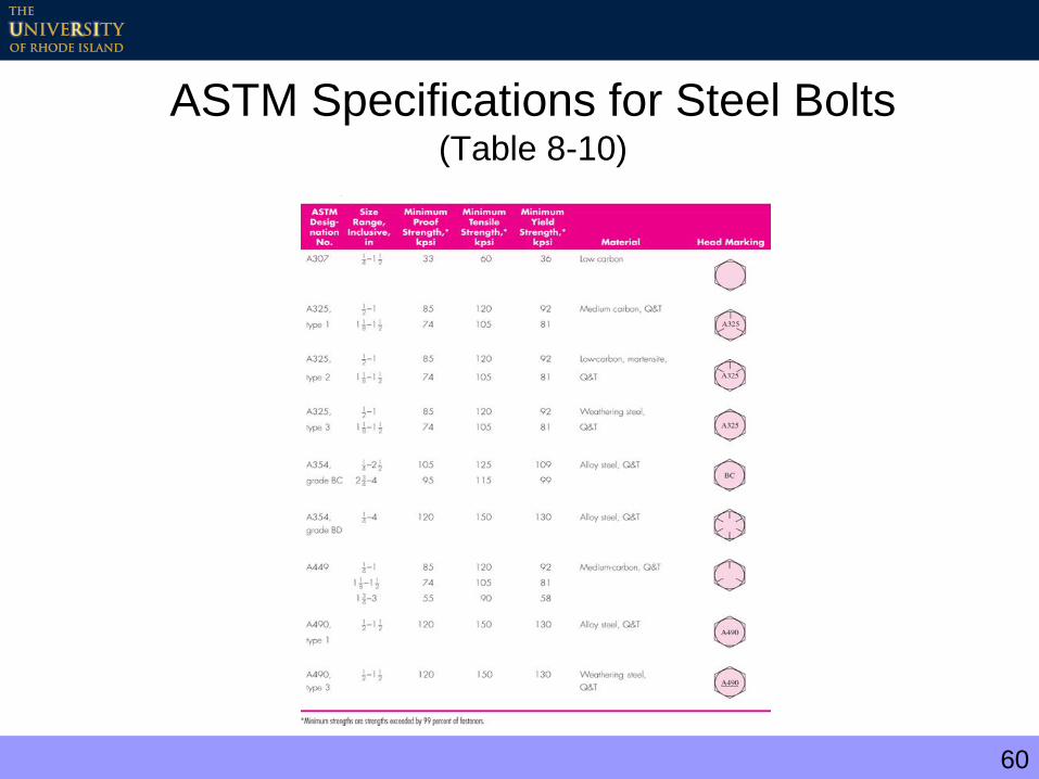
ASTM Specifications for Steel Bolts(Table 8-10)
61
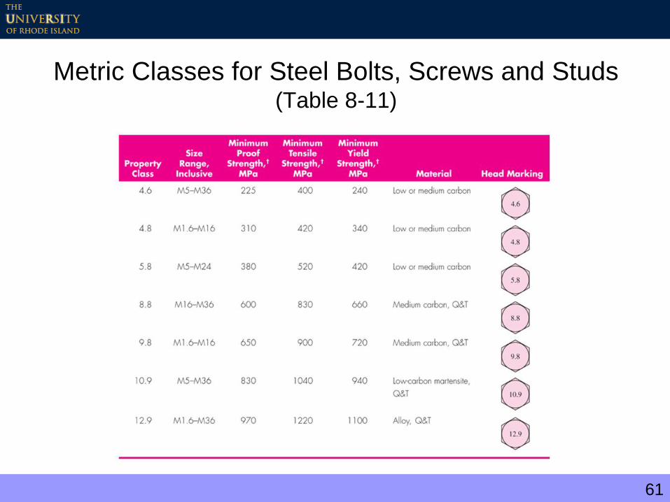
Metric Classes for Steel Bolts, Screws and Studs(Table 8-11)
62
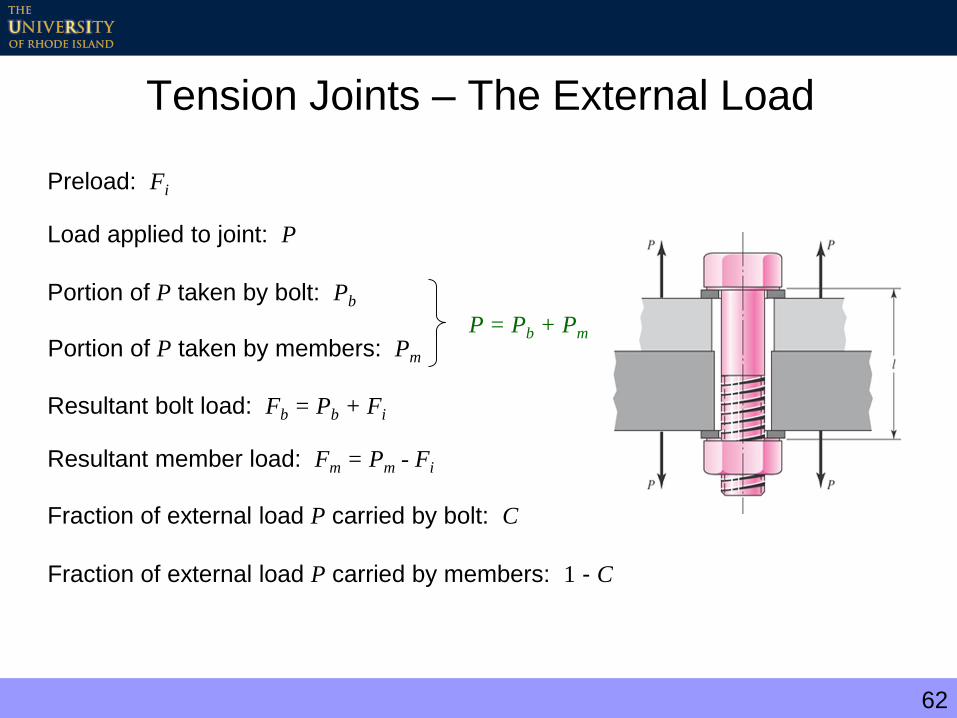
Tension Joints – The External Load
Preload: Fi
Load applied to joint: P
Portion of P taken by bolt: Pb
Portion of P taken by members: Pm
P = Pb + Pm
Resultant bolt load: Fb = Pb + Fi
Resultant member load: Fm = Pm - Fi
Fraction of external load P carried by bolt: C
Fraction of external load P carried by members: 1 - C
63
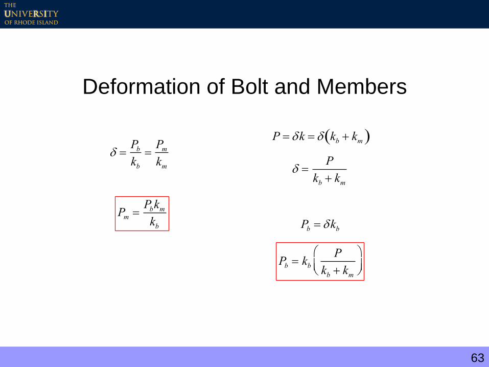
Deformation of Bolt and Members
Pb
kbPm
km
Pm Pbkm
kb
P k kb km
P
kb km
Pb kb
Pb kbP
kb km
64
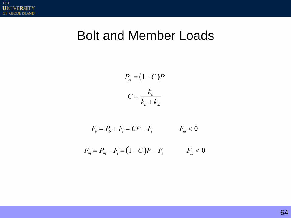
Bolt and Member Loads
Pm 1C P
C kb
kb km
Fb Pb Fi CP Fi Fm 0
Fm Pm Fi 1C P Fi Fm 0

65
Example Bolt and Member Stiffnesses(1/2 in – 13 NC steel bolts)
C – fraction of load carried by bolt (< 20%)
(1-C) - fraction of load carried by members
66
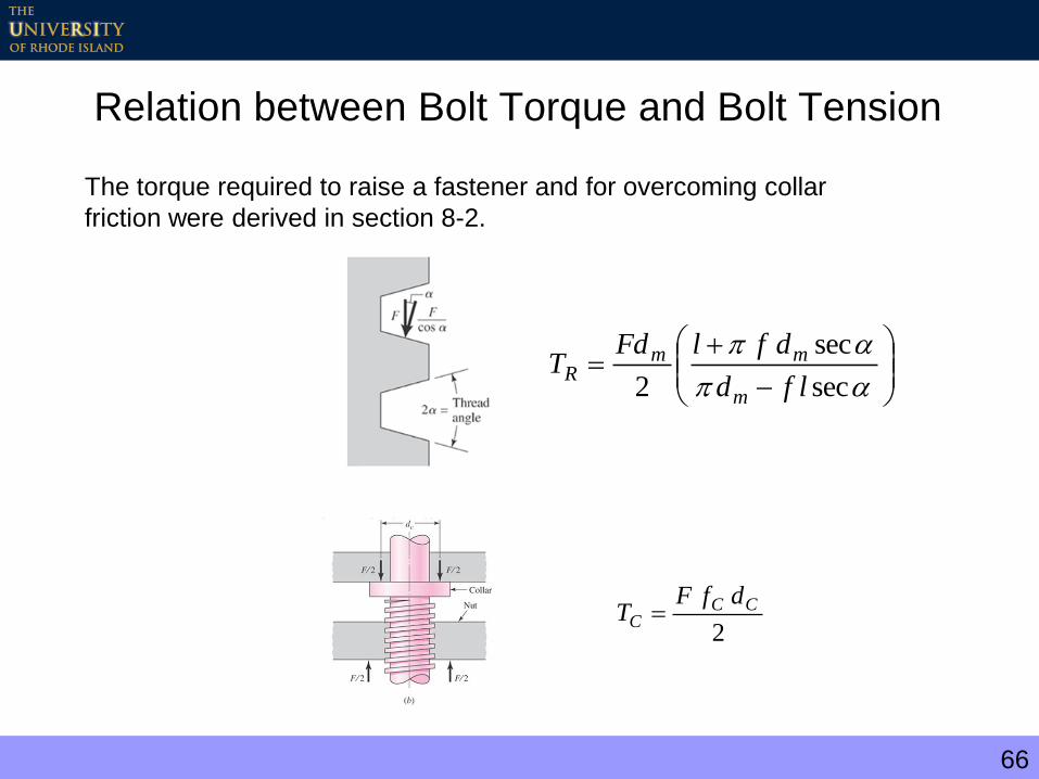
Relation between Bolt Torque and Bolt Tension
The torque required to raise a fastener and for overcoming collar
friction were derived in section 8-2.
sec
sec
2 lfd
dflFdT
m
mmR
2
CCC
dfFT
67
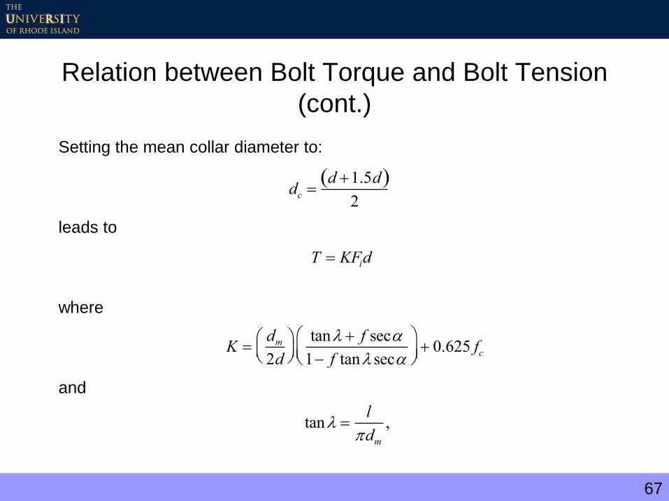
Relation between Bolt Torque and Bolt Tension
(cont.)
Setting the mean collar diameter to:
leads to
where
and
dc d 1.5d 2
T KFid
K dm
2d
tan f sec
1 f tan sec
0.625 fc
tan l
dm,
68
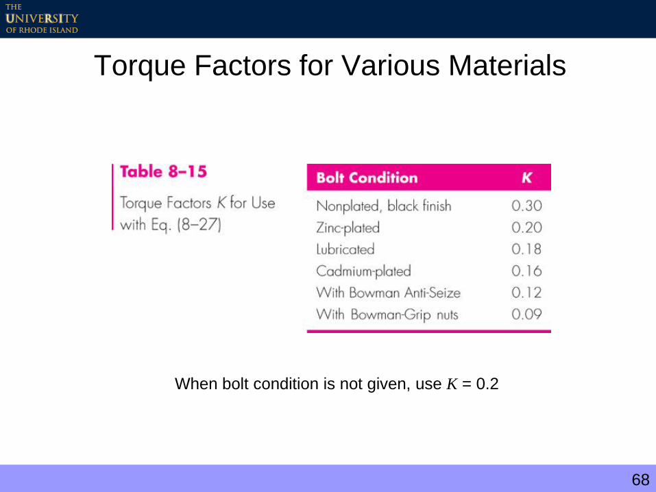
Torque Factors for Various Materials
When bolt condition is not given, use K = 0.2

69
Example 8-3
70
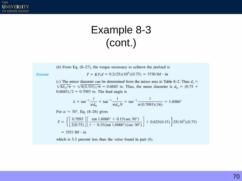
Example 8-3
(cont.)
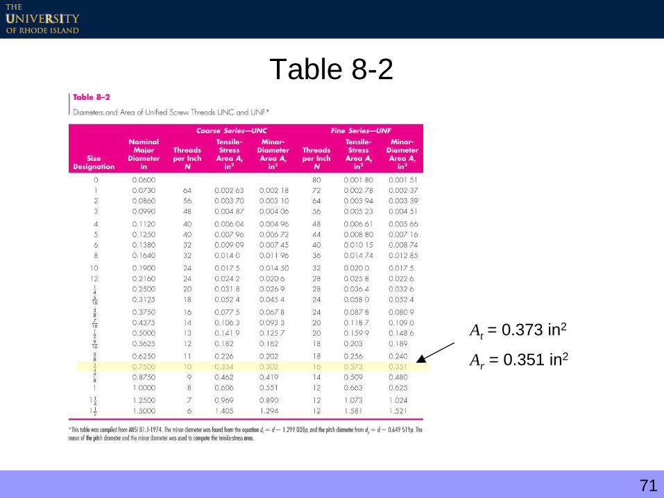
71
Table 8-2
At = 0.373 in2
Ar = 0.351 in2
72
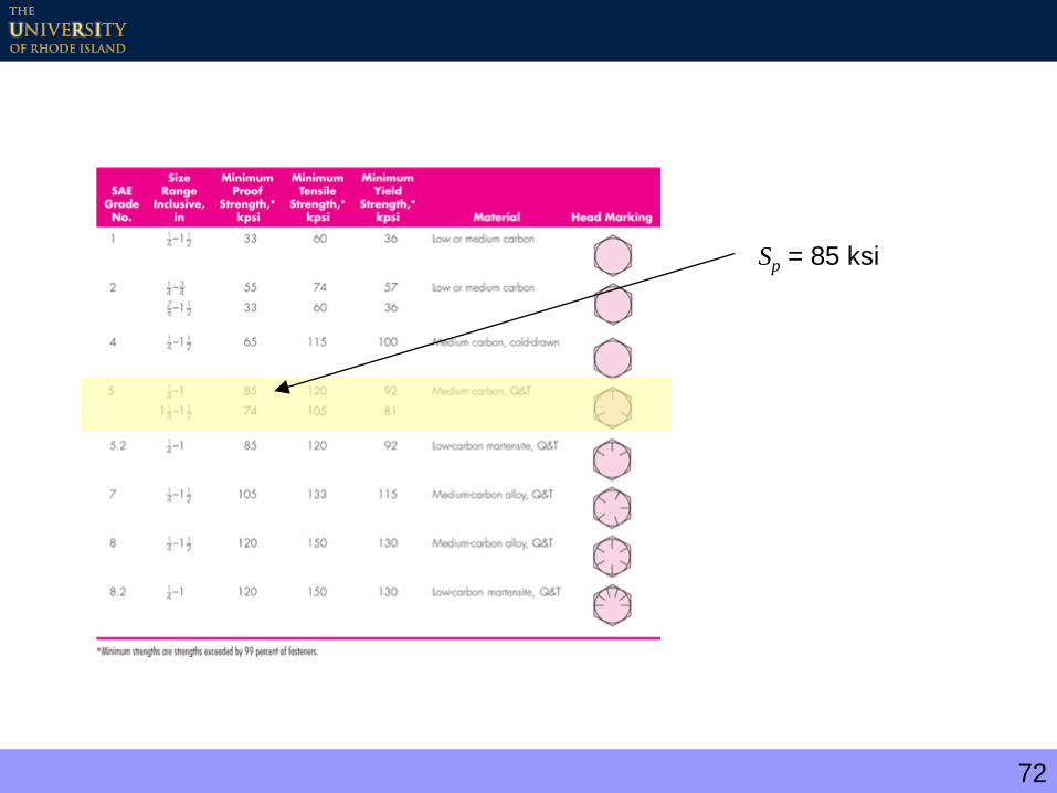
Table 8-9
Sp = 85 ksi

73
Tension Joint with Preload
b CP
AtFi
At
n SpAt Fi
CP
PnP
The total tensile stress in bolt
Introducing a load factor, n, where
and solving for n gives
where n is the load factor associated with bolt strength
74
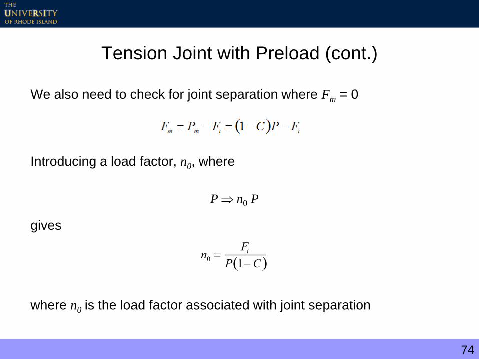
Tension Joint with Preload (cont.)
We also need to check for joint separation where Fm = 0
Introducing a load factor, n0, where
gives
where n0 is the load factor associated with joint separation
PnP 0
n0 Fi
P 1C

75
Recommended Preload
sconnectionpermanentforF
fastenersreusedsconnectionntnonpermaneforFF
p
p
i ,90.0
,,75.0
ptp SAF
Where the proof load is given by
76
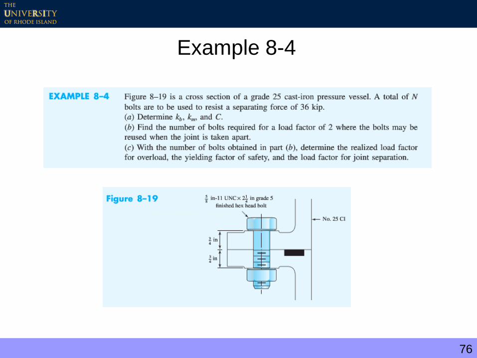
Example 8-4

77
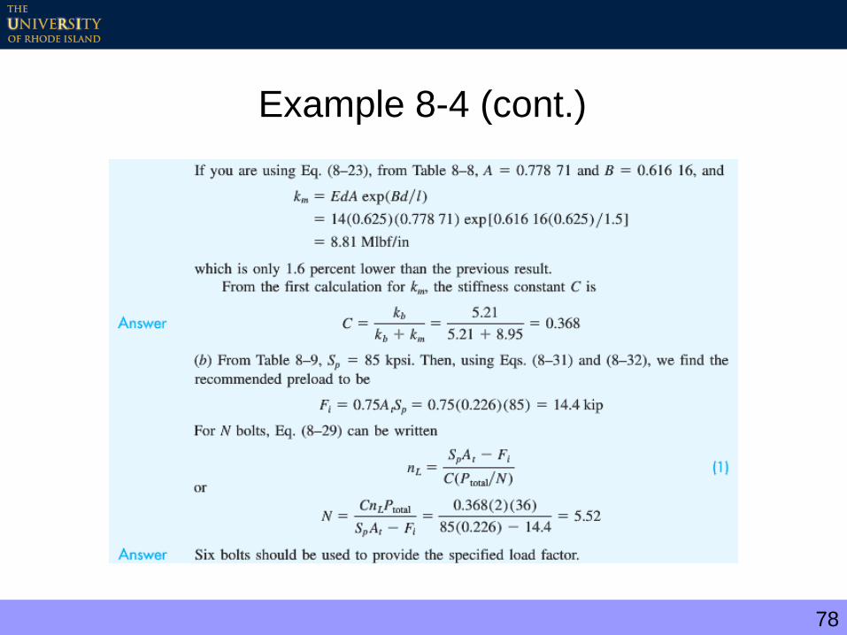
Example 8-4 (cont.)
78
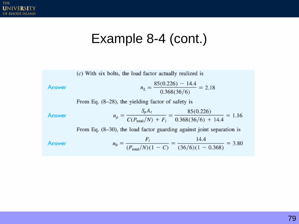
Example 8-4 (cont.)
79
Example 8-4 (cont.)

80
Example 8-4 Summary
0.0
10.0
20.0
30.0
40.0
50.0
0.0 10.0 20.0 30.0 40.0 50.0
Bo
lt L
oa
d (
ksi)
External Load (kip)
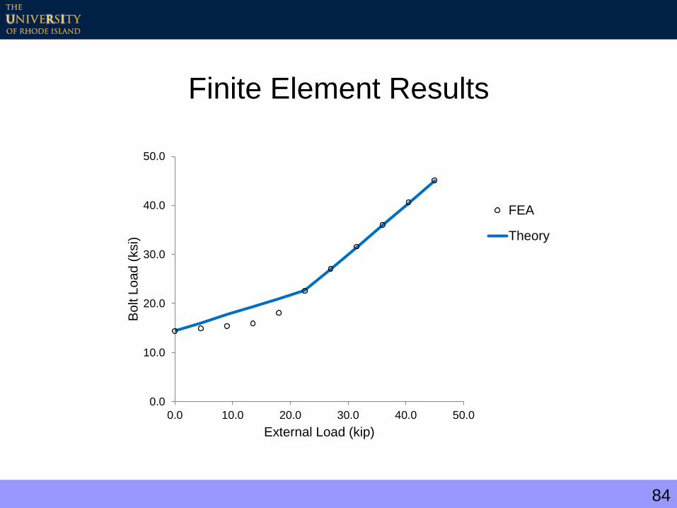
For P < 22.8 kip
Bolt load = 14.4 + 0.368 * P
Plates separate when
P=3.80 (6 kip) = 22.8 kip
For P > 22.8 kip
Bolt load = P
81
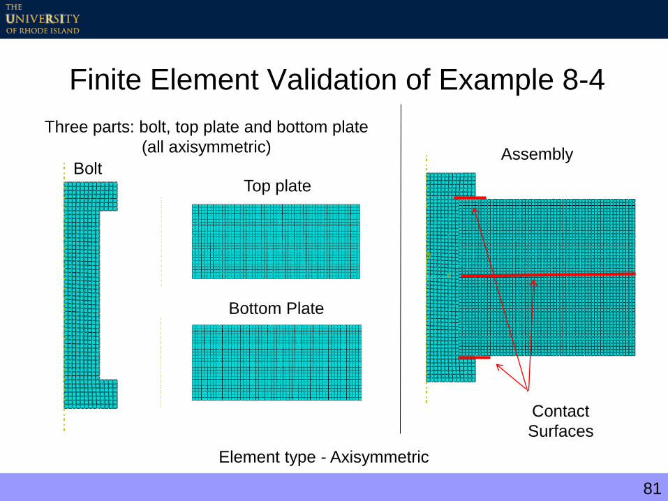
Finite Element Validation of Example 8-4
Bolt
Bottom Plate
Top plate
Assembly
Contact
Surfaces
Element type - Axisymmetric
Three parts: bolt, top plate and bottom plate
(all axisymmetric)
82
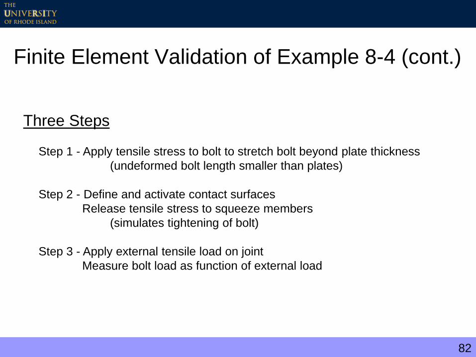
Finite Element Validation of Example 8-4 (cont.)
Three Steps
Step 1 - Apply tensile stress to bolt to stretch bolt beyond plate thickness
(undeformed bolt length smaller than plates)
Step 2 - Define and activate contact surfaces
Release tensile stress to squeeze members
(simulates tightening of bolt)
Step 3 - Apply external tensile load on joint
Measure bolt load as function of external load

83
Finite Element Results - Animation
http://personal.egr.uri.edu/taggart/courses/mce301/ex84/ex84.html
84
Finite Element Results
0.0
10.0
20.0
30.0
40.0
50.0
0.0 10.0 20.0 30.0 40.0 50.0
Bo
lt L
oa
d (
ksi)
External Load (kip)
FEA
Theory

85
Gasketed Joints
Gaskets – used to prevent leaks at joints

86
Gasketed Joints
The bolt tension determines the pressure acting on the gasket. For N bolts, the
pressure is
Substituting
Gives
For uniform pressure on the gaskets, the recommended distance between the
bolts should be between 3 and 6 times the bolt diameter
where Db is the bolt circle diameter
g
iA
NCnPFp 1
NA
Fp
g
m
im FnPCF 1
63 dN
Db

87
Bolted and Riveted Joints in Shear
F
F
88
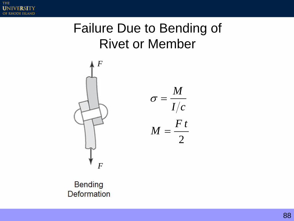
Failure Due to Bending of
Rivet or Member
2
tFM
cI
M
F
F
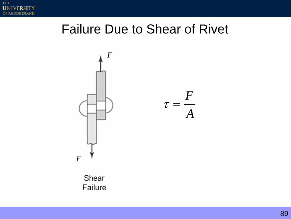
89
Failure Due to Shear of Rivet
A
F
F
F
90
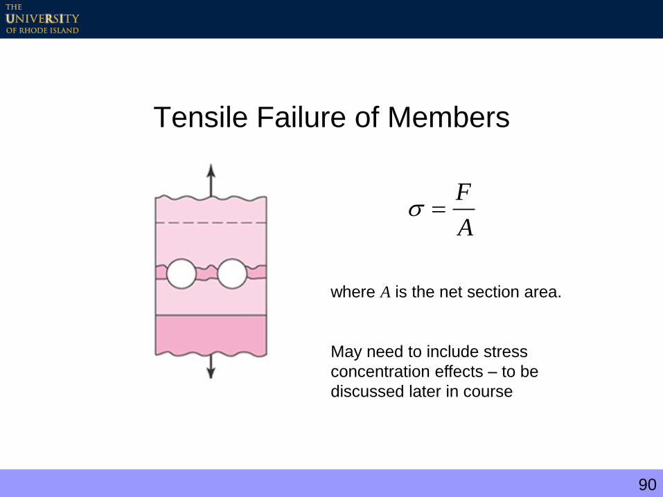
Tensile Failure of Members
A
F
where A is the net section area.
May need to include stress
concentration effects – to be
discussed later in course
91
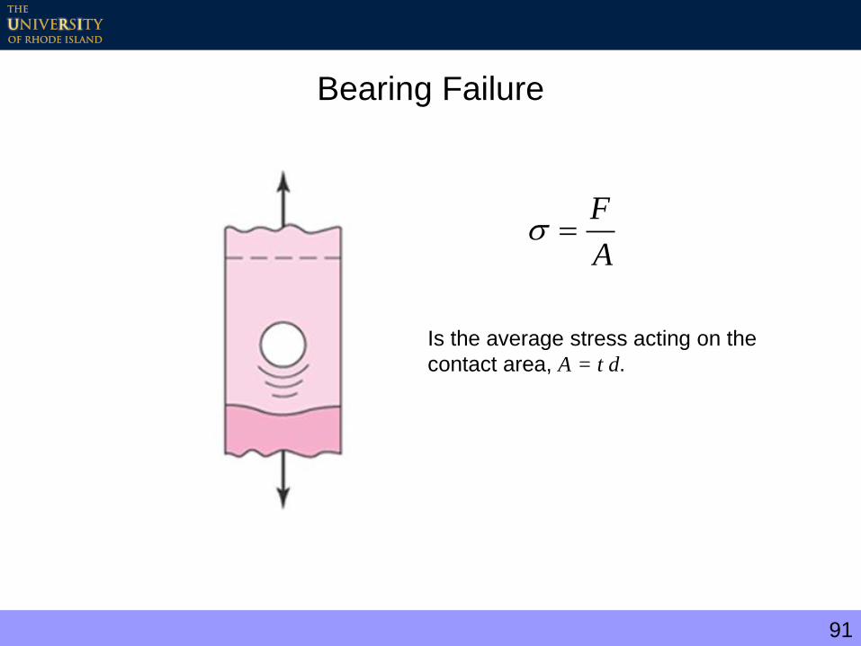
Bearing Failure
A
F
Is the average stress acting on the
contact area, A = t d.

92
Tear-out Failures
Shear Tear-out Failure Tensile Tear-out Failure
Tear-out failure can usually be avoided by placing the bolt or
rivet far enough from the edge
at
F
2
93
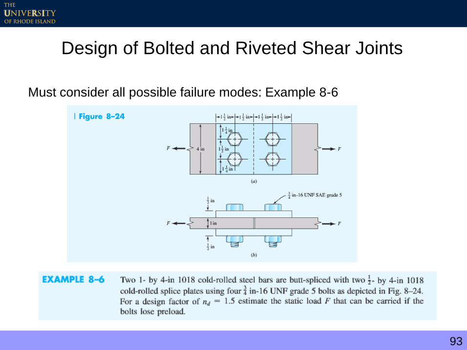
Design of Bolted and Riveted Shear Joints
Must consider all possible failure modes: Example 8-6
94
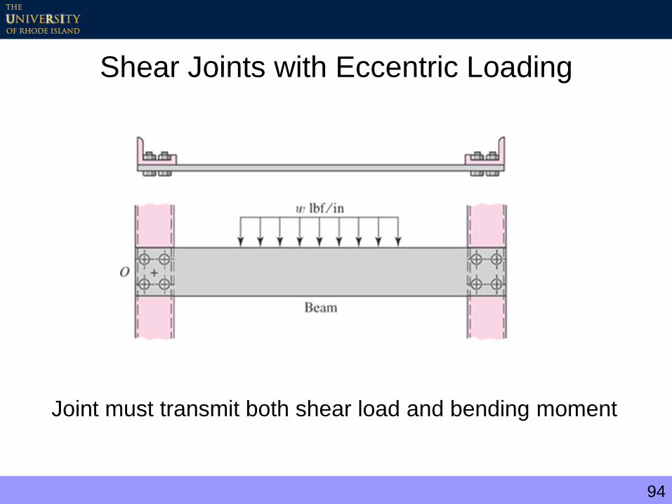
Shear Joints with Eccentric Loading
Joint must transmit both shear load and bending moment

95
Joint Loads
Direct load (primary shear)
Moment load (secondary shear)
n
VF 1'
DDCCBBAA rFrFrFrFM """"1
96
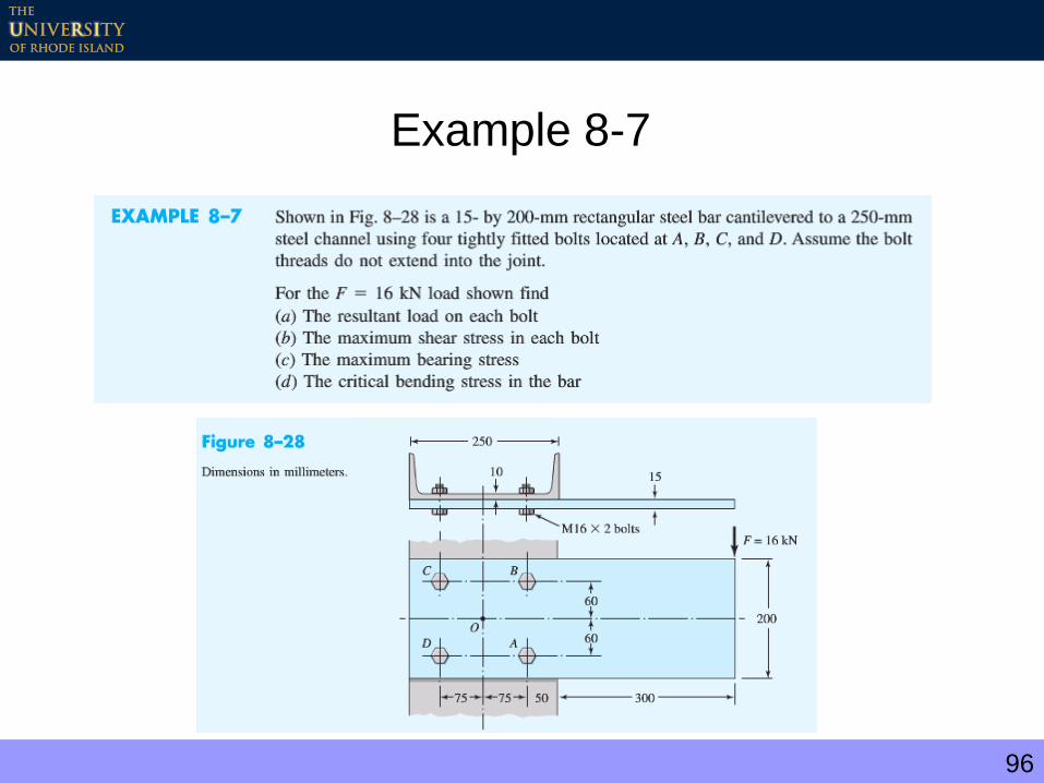
Example 8-7
97
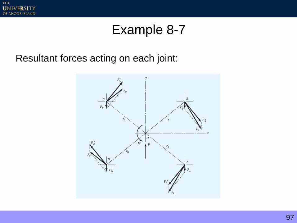
Example 8-7
Resultant forces acting on each joint:


![[Corus] Design of SHS Welded Joints](https://img.pdfslide.us/doc/110x75/577d1fe51a28ab4e1e918f6a/corus-design-of-shs-welded-joints.jpg)