Embed Size (px)
Citation preview
Design of Multilayer Dielectric MirrorsOptimized for Femtosecond Laser Pulses
Fredrik BertilssonBachelor’s thesis
Abstract
A general method for modelling reflection in a multilayer structure is developed. Thisis used to simulate how a Gaussian Ti:sapphire femtosecond pulse reflects off of a peri-odic SiO2/TiO2 dielectric stack at normal incidence. The method is based on a transfermatrix approach combined with the fast Fourier transform in MATLAB. Both a simpleBragg reflector and a linearly chirped mirror is investigated for three different pulsedurations using mirrors with 5, 10, 20 and 40 layer pairs. It is demonstrated that aBragg reflector is not suitable for reflecting a pulse shorter than 10 femtoseconds dueto the limited reflectance bandwidth. The chirped mirror features a wider reflectancebandwidth but a reflected pulse exhibits strong group delay oscillations with wave-length, emanating from unwanted high-order dispersion in the mirror. Designs basedon refined versions of this mirror type can however be used for reflection and disper-sion compensation of pulses as short as 5 femtoseconds.
Division of Atomic PhysicsDepartment of Physics
Supervised by Per Johnsson
May, 2015

Contents
1 Introduction 11.1 Historical background . . . . . . . . . . . . . . . . . . . . . . . . . . . . . . . 11.2 Purpose and motivation . . . . . . . . . . . . . . . . . . . . . . . . . . . . . . 2
2 Background 32.1 Mathematical description of ultrashort pulses . . . . . . . . . . . . . . . . . . 3
2.1.1 Fundamental properties of a wave . . . . . . . . . . . . . . . . . . . . 32.1.2 Temporal and spectral description . . . . . . . . . . . . . . . . . . . . 42.1.3 Dispersive media . . . . . . . . . . . . . . . . . . . . . . . . . . . . . . 62.1.4 Parameters to describe pulse dispersion . . . . . . . . . . . . . . . . . 7
2.2 On the refractive index . . . . . . . . . . . . . . . . . . . . . . . . . . . . . . . 82.3 The Fresnel equations of transmission and reflection . . . . . . . . . . . . . . 82.4 Scattering and transfer matrices . . . . . . . . . . . . . . . . . . . . . . . . . . 102.5 The transfer matrix method . . . . . . . . . . . . . . . . . . . . . . . . . . . . 132.6 Dielectric mirrors . . . . . . . . . . . . . . . . . . . . . . . . . . . . . . . . . . 13
2.6.1 The Bragg reflector . . . . . . . . . . . . . . . . . . . . . . . . . . . . . 142.6.2 More complex designs . . . . . . . . . . . . . . . . . . . . . . . . . . . 142.6.3 Manufacturing techniques . . . . . . . . . . . . . . . . . . . . . . . . . 15
3 Method 153.1 General description . . . . . . . . . . . . . . . . . . . . . . . . . . . . . . . . . 153.2 The input pulse . . . . . . . . . . . . . . . . . . . . . . . . . . . . . . . . . . . 163.3 Refractive indices and mirror designs . . . . . . . . . . . . . . . . . . . . . . 173.4 Evaluating the results . . . . . . . . . . . . . . . . . . . . . . . . . . . . . . . . 18
4 Results and discussion 184.1 The Bragg mirror . . . . . . . . . . . . . . . . . . . . . . . . . . . . . . . . . . 184.2 The linearly chirped mirror . . . . . . . . . . . . . . . . . . . . . . . . . . . . 214.3 Accuracy of the simulations . . . . . . . . . . . . . . . . . . . . . . . . . . . . 24
5 Summary and outlook 25
List of abbreviations
as attosecond
EM electromagnetic
FFT fast Fourier transform
fs femtosecond
FWHM full width at half maximum
GD group delay
GDD group delay dispersion
GVD group velocity dispersion
HHG high-order harmonic generation
IFFT inverse fast Fourier transform
KLM Kerr-lens mode locking
TE transverse electric
TM transverse magnetic
TMM transfer matrix method
1 INTRODUCTION
1 Introduction
1.1 Historical backgroundSince the first light of the laser in 1960, physicists have endeavoured to produce increas-ingly shorter pulses of laser light. The lasers of fundamental importance for today’s re-search on ultrashort pulses operate with pulse durations on the order of femtoseconds(a femtosecond, 1 fs, is a millionth of a billionth of a second, 10−15 seconds). Such lasershave been around since the 1970s in the form of so called dye lasers, the laser type used inthe experiments where femtosecond pulses were first produced [1]. However, dye lasersquickly proved to be far from ideal for short pulse generation: they deteriorate quickly,are weak in terms of output power and the highly toxic dye laser medium makes themcomplicated to handle.
Rapid progress was made when the much more versatile titanium-sapphire (commonlywritten Ti:sapphire) laser was introduced in the mid 1980s. This laser can be tuned tooperate anywhere in a broad spectrum of wavelengths ranging from around 650 nm(1 nm = 10−9 m) to around 1100 nm. Such a broad bandwidth makes it highly suitablefor short pulse generation. Most common to this day is operation at a wavelength of800 nm (near infrared) where the Ti:sapphire lasing efficiency is at maximum. With tech-niques such as Kerr-lens mode locking (KLM), pulses of duation 5 fs (shorter than twooptical cycles at 800 nm) have been achieved using Ti:sapphire lasers [2].
There are several areas of research where ultrashort pulses play an essential role. Forexample: to probe chemical reactions occuring on very short time scales, high temporalresolution is needed. One can make an analogy with photography: a high shutter speedis required if a moving object is to appear sharp in an image. Apart from probing fastchemical processes, a high-intensity femtosecond pulse can also stimulate certain reac-tions to occur. A pulse used in this manner is commonly referred to as a pump pulse. Anexperiment where the reaction is initiated by and then characterized with the same pulseis known as a pump-probe experiment. That is a very common approach in the field offemtochemistry, the study of very fast chemical processes.1.
It is also possible to produce even shorter pulses of attosecond duration (1 as = 10−18
seconds) using femtosecond pulses. This happens in a process known as high-order har-monic generation (HHG), caused by the fact that the very high electric field of the laserpulse becomes comparable to the intra-atomic electric fields. Electrons in an atom tar-geted by the pulse can then escape the atomic potential and later recombine with theatom, thereby emitting attosecond pulses with wavelengths in the extreme ultravioletrange. Several pioneering experiments on HHG have been performed in Lund, both re-garding pulse generation itself [4], [5] and characterization and applications of the gener-ated pulses [6]. The pulses can be used to probe some of the fastest atomic and molecularphenomena occurring in nature [7].
1For a comprehensive summary of this field of research, see Ref. [3]
1
1.2 Purpose and motivation 1 INTRODUCTION
1.2 Purpose and motivationA fundamental problem regarding ultrashort pulses is that they are inevitably distortedby ordinary optical components. After propagation through such components, the pulsewill become severely broadened and might not even maintain its initial shape. Similardispersive effects occur when such a short pulse traverses air (but not vacuum). At theend of an optical setup, it is thus likely that the pulse characteristics have become un-suitable for the intended application. The same problem can occur inside a laser in itsresonating cavity.
The unwanted dispersion can be prevented or more or less effectively compensated forusing more sophisticated optics. Since it may sometimes also be desirable to manipulatethe initial pulse shape or duration, components can be tailored for such purposes as well.These components can for example be lenses, prism pairs2, metallic filters or special mul-tilayer mirrors known as dielectric mirrors. The latter have an additional advantage overordinary mirrors since they can provide a much higher reflectance.
The purpose of this thesis is first and foremost to devise a simple and intuitive modelwhich accurately describes the optical properties of a multilayer structure. More precisely,the aim is to study how well multilayer dielectric mirrors of varying design reflect a fem-tosecond pulse. How the shape of such a mirror shall be tailored to preserve the shapeof an initially non-dispersed pulse and at the same time provide a very high reflectanceis investigated. In this study, the materials of the constituting layers are chosen to besilicon dioxide (SiO2, known as fused silica) and titanium dioxide (TiO2) since they arecommonly used in dielectric mirrors due to their suitable refractive indices. The mirror ismodelled in MATLAB using a matrix approach together with the fast Fourier transform(FFT): the mirror acts as frequency domain filter. Each frequency component of the pulseis filtered separately since the refractive indices of SiO2 and TiO2 are frequency depen-dent. The spectral and temporal characteristics of the reflected pulse are then evaluatedtogether with the mirror reflectance over a relevant frequency range. This is done forseveral different mirror designs and input pulse durations.
The thesis is organized as follows. In section 2 the theoretical background necessary tounderstand the results is treated. This starts with the mathematics of wave and pulsepropagation followed by a discussion on the optical properties of dielectric media. Thebasis for the numerical method which the thesis is based on is then developed. The sec-tion concludes with a description of different dielectric mirror designs. In section 3 themethod and analysis framework used is detailed. Section 4 is devoted to treating theresults obtained in the simulations: the limits and prospects of each mirror design is dis-cussed. The thesis is concluded in section 5 with an outlook reviewing current and futureresearch on reflection and dispersion compensation of ultrashort pulses.
2Has been used for a Ti:sapphire laser [8].
2
2 BACKGROUND
2 Background
2.1 Mathematical description of ultrashort pulsesThe material in this section is based on the treatment of the subject in sections 2.1, 2.2, 2.6,5.6 and 22.1-3 in Ref. [9].
2.1.1 Fundamental properties of a wave
Light propagating in vacuum can be described as an electromagnetic (EM) wave withboth the electric field E and the magnetic field B transverse to the direction of propagation.For propagation in the z-direction, the E-field amplitude E(z, t) satisfies the wave equation:
∂2E(z, t)∂z2 =
1c2
0
∂2E(z, t)∂t2 , (1)
where c0 is the speed of light in vacuum and t is time. The B-field amplitude B(z, t) sat-isfies an analogous equation. The behavior of the EM-wave can be completely describedusing either the electric or the magnetic field, since there is at all times a relation betweenE and B from Maxwell’s equations: E = B/c0. In this treatment, E(z, t) is used. The mostsimple solution to the wave equation above is a sinusoidal wave of a single frequency ν:
E(z, t) = A cos(ωt + ϕ(z)), (2)
where A is the (real) amplitude of the wave, ω = 2πν is the angular frequency and ϕ isa phase which translates the wave in the z-direction. The electric field amplitude is a realparameter, but it is conveniently described using a complex amplitude U written in termsof an exponential:
U(z, t) = Aei(ωt+ϕ(z)). (3)
U(z, t) also satisfies the wave equation, with the same boundary conditions as E(z, t). Us-ing Euler’s formula we get the following relation between real and complex amplitudes.
E(z, t) = <[U(z, t)] =12[U(z, t) + U∗(z, t)]. (4)
It is now handy to separate U into its temporal and spatial parts, so that
U(z, t) = U(z)eiωt, (5)
where U(z) = Aeiϕ(z) is the complex amplitude. We therefore get the phase from theargument of U(z) and the amplitude from |U(z)|. If U is inserted into the wave equationit satisfies, we get the one-dimensional Helmholtz equation
∂2U(z, t)∂z2 + k2
z U(z, t) = 0, (6)
3
2.1 Mathematical description of ultrashort pulses 2 BACKGROUND
where kz = ω/c0 is the wave number: the spatial equivalent of the temporal angularfrequency. This parameter is proportional to how many wavelengths λ = c0/ν there isper unit length, and will be important later.
In many situations, the intensity I(z, t) of a wave is a more important parameter thanthe electric field itself. It is proportional to the square of the E-field and a convenientdefinition is
I(z, t) ∝ 2〈E2(z, t)〉, (7)where 〈· · ·〉 denotes time average. Inserting the expression for E in eq. (4) into the abovedefinition, writing the exponentials of U and U∗ in terms of sines and cosines and thentime-averaging the surviving cosine term, one obtains that
I(z, t) ∝ |U(z)|2 . (8)Therefore, the complex amplitude is of key interest. For a monochromatic (plane) waveits phase term looks like ϕ(z) = −k · z = −kzz. Using this, eq. (5) and Euler’s formula,the full complex electric field can be written as
U(z, t) = A ei(ωt−kzz) = A eiω(t− zc0). (9)
From this, both the spatial and temporal periodicity is clearly seen. It is also evident thatfor a given t, the overall phase of the wave depends on z/c0. The velocity c0 is thereforeknown as the phase velocity, which in this special case is the same as the propagation speedof the wave itself. If the wave propagates through a medium of refractive index n, itsphase velocity is lowered by this factor: it immediately follows that λ must decrease withthe same factor (so that k increases by n). The frequency thus stays the same regardless ofn. The physical meaning of the refractive index will be elaborated on in section 2.2.
2.1.2 Temporal and spectral description
Wave equations on the form of eq. (1) are said to be linear. This means that if U1 andU2 are separate solutions, the sum of the solutions U = U1 + U2 is also a valid solution.Hence, one may construct any wave as a superposition of a (possibly infinite) numberof individual plane waves. Since a plane wave is not localized in space it is not a verygood description of real waves which are always localized in some way. Superimposingmany plane waves of different wave numbers, it is possible to create a localized wavepacket. Such a construct may accurately describe a wave only occupying a certain spaceat a given time, known as a pulse. It is very convenient to describe a pulse using thepowerful Fourier transform approach. As implied above, a certain wave E(t) at a certainposition z may be written as a sum of plane waves, each of a unique amplitude E(ω):
E(t) =1
2π
∫ ∞
−∞E(ω)e−iωtdω. (10)
Conversely, for a given E(t) one may obtain its frequency components E(ω):
E(ω) =∫ ∞
−∞E(t)eiωtdt, (11)
4
2.1 Mathematical description of ultrashort pulses 2 BACKGROUND
known as the spectrum. Eq. (11) is the familiar Fourier transform. If E(t) is a real functionthe negative frequency components are the complex conjugates of the positive ones. Toavoid having to work with negative frequencies, one may just as before use a complexwave U. Then, U(ω) = −U(ω): for U(t) the Fourier components are symmetricallydistributed around zero. Thus the integral in eq. (10) can instead be written from zero toinfinity multiplied by a factor of two. Due to the linearity mentioned before, the real fieldE(t) represented by the complex U(t) can be obtained by an equation analogous to eq.(4).
The intensity is of a pulsed wave is given by the squared modulus of its complex ampli-tude U(z, t). This can be motivated as follows. The intensity can be obtained as in eq. (7):insertion into this equation and subsequent rewriting leads to
I(z, t) ∝ 2〈E2(z, t)〉 = 12〈U2(z, t)〉+ 1
2〈U∗2(z, t)〉+ 〈U(z, t)U∗(z, t)〉. (12)
It can easily be shown that the two first terms oscillate at much higher frequency than thethird term, which only contains differences of frequencies. Doing the time averaging overa sufficiently long time will then make the two first terms average out to zero so that onlythe last term remains, which is the desired result identical to that in eq. (8).
A sufficiently accurate model of the ultrashort pulses emitted by lasers like the Ti:sapphirelaser is the pulsed plane wave. In the time domain, it is simply described by a plane waveof angular frequency ω0 (the central or carrier frequency) with its amplitude modulatedby some complex function C often called the envelope. At any given time and position ina material of (constant) refractive index n and c = c0/n it may thus be written as
U(z, t) = C(
t− zc
)eiω0(t− z
c ). (13)
The temporal width of the envelope function is often described using the full width athalf maximum (FWHM) of I(z, t), here denoted τ0. Spatially the pulse then occupies aFWHM of cτ0. Using the well known frequency shift property of the Fourier transform,U(z, ω) at a given z becomes centered around ω0 so that
U(z, ω) = C(ω−ω0)e−iω zc . (14)
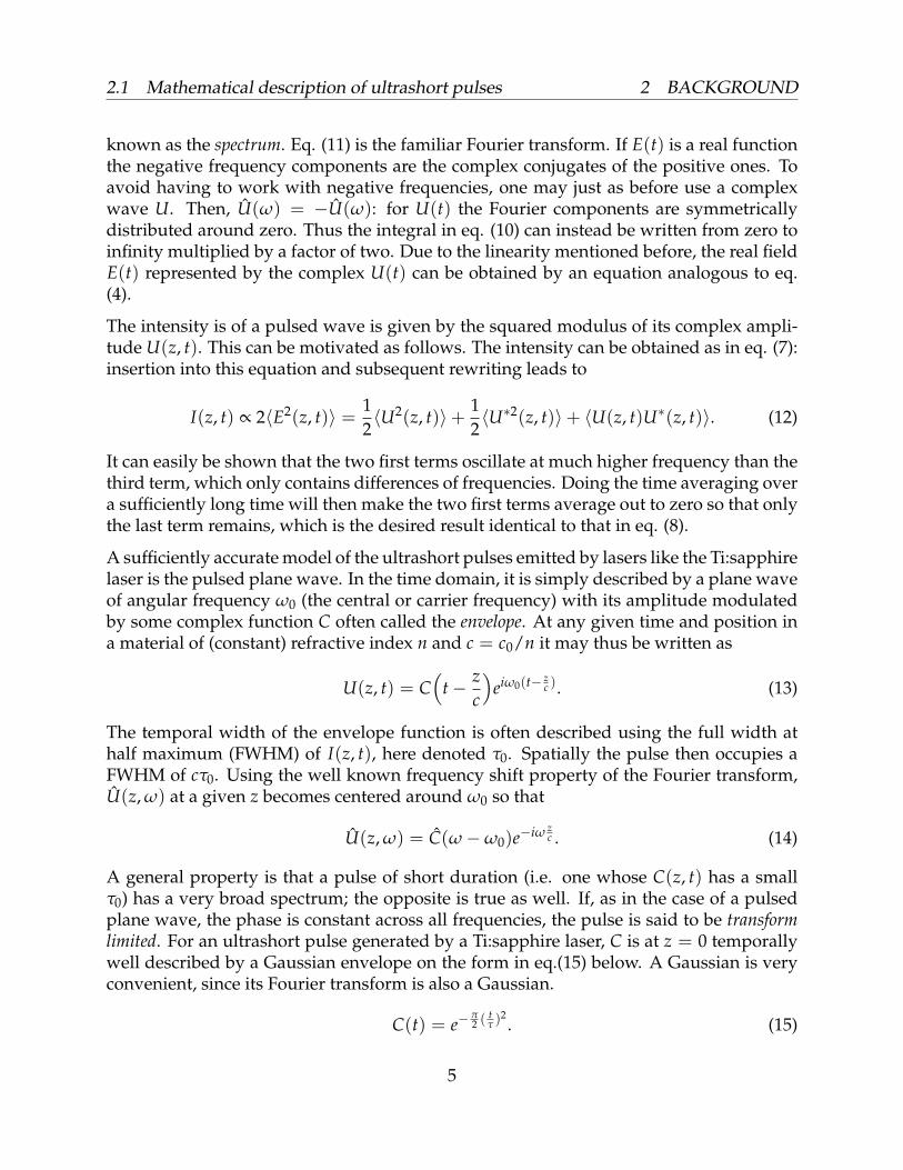
A general property is that a pulse of short duration (i.e. one whose C(z, t) has a smallτ0) has a very broad spectrum; the opposite is true as well. If, as in the case of a pulsedplane wave, the phase is constant across all frequencies, the pulse is said to be transformlimited. For an ultrashort pulse generated by a Ti:sapphire laser, C is at z = 0 temporallywell described by a Gaussian envelope on the form in eq.(15) below. A Gaussian is veryconvenient, since its Fourier transform is also a Gaussian.
C(t) = e−π2 (
tτ )
2. (15)
5
2.1 Mathematical description of ultrashort pulses 2 BACKGROUND
With this definition of a Gaussian envelope, τ is not the FWHM of I(t). Instead τ isthe width of a square (top-hat) pulse which carries the same total energy as the entireGaussian pulse. τ is somewhat smaller than τ0 for a given pulse: we have that τ ≈ 0.94τ0.The product of this temporal duration and the spectral FWHM ∆ω of C is constant: itis referred to as the time-bandwidth product. As a consequence, τ must increase if ∆ωdecreases and vice versa. This is sometimes called the uncertainty relationship between thetime and frequency domains.
2.1.3 Dispersive media
Until now only propagation through a material with frequency independent refractiveindex has been considered. This is rarely the case for real materials: usually n = n(ω).Such a medium is said to be dispersive. A plane wave travelling through such a mate-rial is not affected by this since it is monochromatic. A pulse, which always has a spec-tral width > 0 will however be strongly affected. This is because the phase velocity isc = c0/n(ω) = c(ω), so the different frequency components in the pulse travel at dif-ferent velocities. An initially transform limited pulse will thus, depending on whether nincreases or decreases with frequency, eventually have low or high frequency componentsrespectively in the leading part of the pulse. This is known as a chirped pulse.
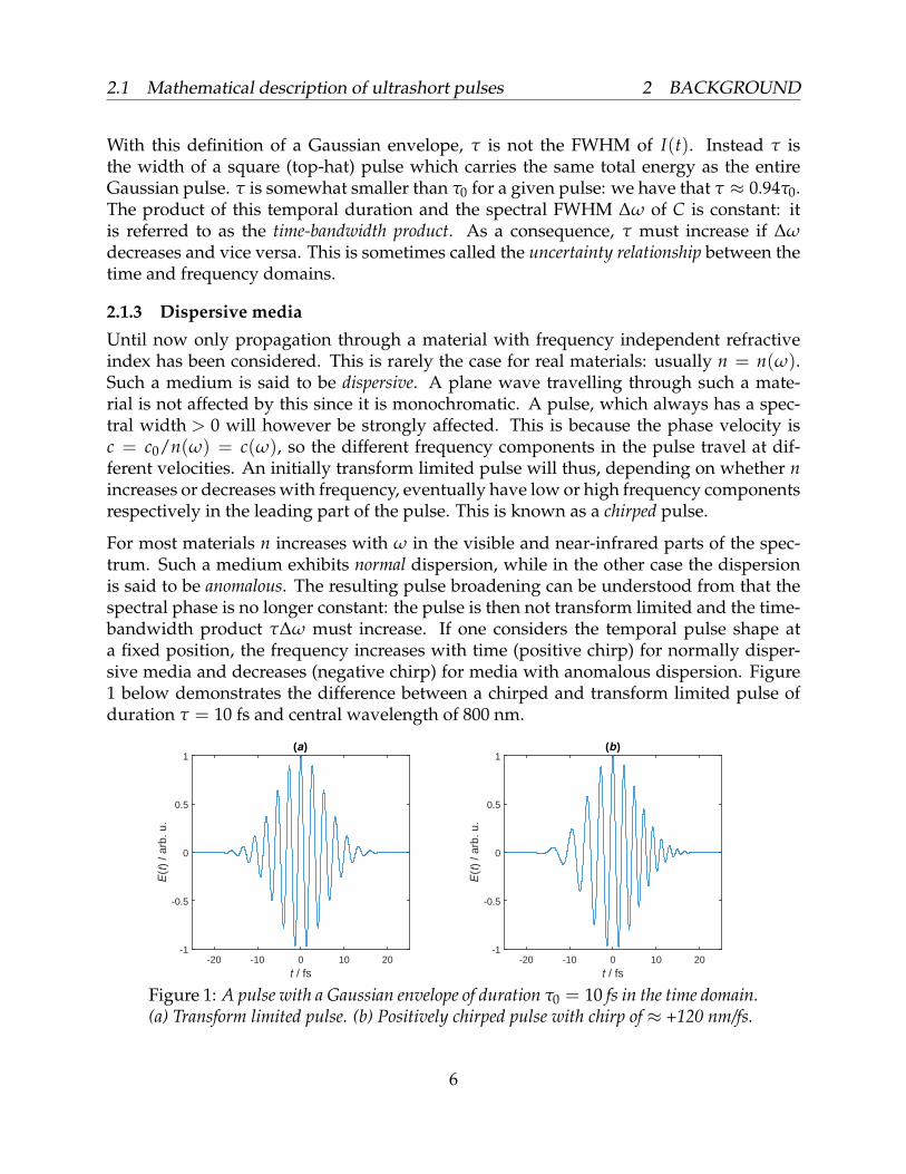
For most materials n increases with ω in the visible and near-infrared parts of the spec-trum. Such a medium exhibits normal dispersion, while in the other case the dispersionis said to be anomalous. The resulting pulse broadening can be understood from that thespectral phase is no longer constant: the pulse is then not transform limited and the time-bandwidth product τ∆ω must increase. If one considers the temporal pulse shape ata fixed position, the frequency increases with time (positive chirp) for normally disper-sive media and decreases (negative chirp) for media with anomalous dispersion. Figure1 below demonstrates the difference between a chirped and transform limited pulse ofduration τ = 10 fs and central wavelength of 800 nm.
t / fs-20 -10 0 10 20
E(t
) / a
rb. u
.
-1
-0.5
0
0.5
1(a)
t / fs-20 -10 0 10 20
E(t
) / a
rb. u
.
-1
-0.5
0
0.5
1(b)
Figure 1: A pulse with a Gaussian envelope of duration τ0 = 10 fs in the time domain.(a) Transform limited pulse. (b) Positively chirped pulse with chirp of ≈ +120 nm/fs.
6
2.1 Mathematical description of ultrashort pulses 2 BACKGROUND
2.1.4 Parameters to describe pulse dispersion
Each component in a pulse starting at z = 0 and propagating in the positive z-directionwill in a dispersive medium obtain a spectral phase
ϕ(ω) = n(ω)k(ω)d, (16)
after a distance z = d. Here k(ω) = ω/c0 is the wave number in vacuum. To observe howϕ(ω) has affected the pulse temporally at z = d, one may simply multiply each spectralcomponent by e−iϕ(ω) and transform back into the time domain. We get:
U(z = d, t) =1π
∫ ∞
0U(z = 0, ω)ei(ωt−ϕ(ω))dω. (17)
It is now instructive to consider the case of a phase shift which varies sufficiently slowlywith ω within the pulse. Then, ϕ(ω) can be Taylor expanded around the carrier frequencyω0 keeping only the first term as below.
ϕ(ω) ≈ ϕ(ω0) +∂ϕ
∂ω
∣∣∣ω=ω0
(ω−ω0
)= ϕ0 + ϕ′(ω−ω0). (18)
Substituting this back into eq. (17), we obtain using δ = ω−ω0 that:
U(z = d, t) ≈ ei(ω0t−ϕ0)
π
∫ ∞
0U(z = 0, δ)eiδ(t−ϕ′)dω =
ei(ω0t−ϕ0)
π
∫ ∞
−ω0
U(z = d, δ) dδ. (19)
The exponential outside the integral corresponds to the carrier frequency wave, movingwith its phase velocity k0 = ω0/c. The integral describes the pulse envelope, which at thecentral frequency travels at the group velocity vg. It can be easily obtained by dimensionalanalysis of the exponential inside the integral:
vg(ω0) =dω
d(kn(ω))
∣∣∣ω=ω0
. (20)
Differentiating eq. (20) again, one obtains zero. What this means is that the pulse envelopeis not distorted by the first term in the Taylor expansion in any way: it merely delays itby an amount TG = d/vg known as group delay (GD). It can also be deduced that thegroup velocity is the same as the phase velocity at ω0 if n is independent of ω, whichis equivalent to including only one term in the expansion. However, if the pulse has ahigher bandwidth (implying a shorter pulse), it will be necessary to include higher orderterms. Such terms express a frequency dependent group delay and group velocity. Thesecond term, for example, is called the group delay dispersion (GDD) and is written
GDD =d2ϕ(ω)
dω2 . (21)
This term is responsible for the broadening and chirping effects that have been discussedin section 2.1.3. A related parameter is the group velocity dispersion (GVD) which is theGDD per unit length. One can continue and write the the third, fourth and higher orderdispersion terms with their corresponding derivatives. These terms will alter the pulseshape in more complicated ways. For propagation in a material which has a given n(ω),high order terms become increasingly important with decreasing pulse duration.
7
2.2 On the refractive index 2 BACKGROUND
2.2 On the refractive indexThe refractive index of a material where the phase velocity is c for a given frequencyis related to the electric permittivity ε = ε0εr and magnetic permeability µ = µ0µr, withsubscripts 0 and r indicating vacuum and relative permittivity/permeability. εr and µr arein turn dimensionless quantities related to the electric and magnetic susceptibilities χe =εr− 1 and χm = µr− 1. These determine how well a material is polarized/magnetized bythe electric/magnetic components of the light wave as it propagates through the material.With the above relations, we can write
n =c0
c=
√εµ
ε0µ0=√
εrµr. (22)
The materials of relevance in this thesis are dielectrics, which means that they are easilypolarized by external electric fields but not very easily magnetized. Thus, µ ≈ µ0 is areasonable approximation to make for such materials.
In the two sections above it has been assumed that no absorption occurs in the material:that the EM wave is not attenuated as it propagates. Absorption can easily be incorpo-rated into the model by introducing a complex refractive index nc = n + iα with α beingthe attenuation coefficient. This imaginary part adds a real term in the exponent of the com-plex wave U(z, t) = eiω(t−z/c), which thus becomes attenuated as z increases. However,for many dielectrics α ≈ 0 in the visible and near infrared region. For the small propa-gation distances of relevance in this thesis it is thus reasonable to neglect absorption andonly include the real part n.
2.3 The Fresnel equations of transmission and reflectionConsider a plane EM-wave of wave vector k propagating in a dielectric of refractive indexn1 encountering a boundary to a dielectric of index n2 at an angle θ1 to the boundarynormal. If there is no absorption, the wave will split into a refracted component k’ anda reflected component k”. Figure 2 on page 9 illustrates the situation. The ratio of theamplitudes depends on θ1, n2/n1 and the incident wave polarization. If the polarizationis such that the electric field is orthogonal to the plane spanned by k and k”, it is saidto be transverse electric (TE) or σ-polarized. The other case is transverse magnetic (TM)or π-polarization. An arbitrarily polarized wave is thus a linear combination of thesepolarization modes. Each mode is considered separately in the treatment that follows.The relationship between angles of incidence and refraction is determined by Snell’s law:
n1 sin θ1 = n2 sin θ2. (23)
We also have that θ1 = θ3 which is the law of reflection. These two results are independentof the polarization, however the amplitudes and phases of the refracted and reflectedwaves are not unless the angle of incidence is zero. Only considering the complex electric
8

2.3 The Fresnel equations of transmission and reflection 2 BACKGROUND
Figure 2: Refraction and reflection of a plane wave with wave vector k incident on aboundary between two dielectrics of different refractive indices. n1 is smaller than n2.
field U, we can write U′ and U′′ for refracted and reflected waves in terms of incident Uusing the complex reflectance r and transmittance t, with the only requirement being that|r| and |t| is≤ 1 from energy conservation. r and t are complex and thus incorporate bothamplitude and phase. For the two polarizations σ and π we get the following relations.
U′σ = tσUσ, U′′σ = rσUσ. (24)
U′π = tπUπ, U′′π = rπUπ. (25)
Now we only need to find r and t. They can be obtained by the boundary conditionsprovided by Maxwell’s equations in materials: the parallel electric component and thetransverse magnetic component must be continuous across the boundary regardless ofthe polarization. This combined with Snell’s law gives the Fresnel equations below3.
rσ =n1 cos θ1 − n2
√1− (n1/n2)2 sin2 θ1
n1 cos θ1 + n2
√1− (n1/n2)2 sin2 θ1
, tσ = 1 + rσ. (26)
rπ =n1 sec θ1 − n2
(√1− (n1/n2)2 sin2 θ1
)−1
n1 sec θ1 + n2
(√1− (n1/n2)2 sin2 θ1
)−1 , tπ =(1 + rπ) cos θ1√
1− (n1/n2)2 sin2 θ1
. (27)
For normal incidence (i.e. θ1 = 0) the Fresnel equations reduce to the following for bothpolarizations:
r =n1 − n2
n1 + n2, t = 1 + r =
2n1
n1 + n2. (28)
3For the full derivation, see pages 302-306 in Ref. [10]
9
2.4 Scattering and transfer matrices 2 BACKGROUND
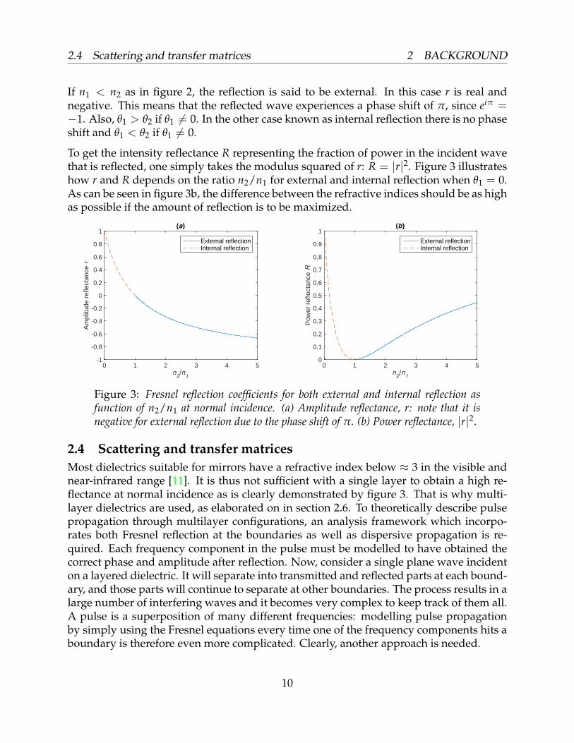
If n1 < n2 as in figure 2, the reflection is said to be external. In this case r is real andnegative. This means that the reflected wave experiences a phase shift of π, since eiπ =−1. Also, θ1 > θ2 if θ1 6= 0. In the other case known as internal reflection there is no phaseshift and θ1 < θ2 if θ1 6= 0.
To get the intensity reflectance R representing the fraction of power in the incident wavethat is reflected, one simply takes the modulus squared of r: R = |r|2. Figure 3 illustrateshow r and R depends on the ratio n2/n1 for external and internal reflection when θ1 = 0.As can be seen in figure 3b, the difference between the refractive indices should be as highas possible if the amount of reflection is to be maximized.
n2/n
1
0 1 2 3 4 5
Am
plitu
de r
efle
ctan
ce r
-1
-0.8
-0.6
-0.4
-0.2
0
0.2
0.4
0.6
0.8
1(a)
External reflectionInternal reflection
n2/n
1
0 1 2 3 4 5
Pow
er r
efle
ctan
ce R
0
0.1
0.2
0.3
0.4
0.5
0.6
0.7
0.8
0.9
1(b)
External reflectionInternal reflection
Figure 3: Fresnel reflection coefficients for both external and internal reflection asfunction of n2/n1 at normal incidence. (a) Amplitude reflectance, r: note that it isnegative for external reflection due to the phase shift of π. (b) Power reflectance, |r|2.
2.4 Scattering and transfer matricesMost dielectrics suitable for mirrors have a refractive index below ≈ 3 in the visible andnear-infrared range [11]. It is thus not sufficient with a single layer to obtain a high re-flectance at normal incidence as is clearly demonstrated by figure 3. That is why multi-layer dielectrics are used, as elaborated on in section 2.6. To theoretically describe pulsepropagation through multilayer configurations, an analysis framework which incorpo-rates both Fresnel reflection at the boundaries as well as dispersive propagation is re-quired. Each frequency component in the pulse must be modelled to have obtained thecorrect phase and amplitude after reflection. Now, consider a single plane wave incidenton a layered dielectric. It will separate into transmitted and reflected parts at each bound-ary, and those parts will continue to separate at other boundaries. The process results in alarge number of interfering waves and it becomes very complex to keep track of them all.A pulse is a superposition of many different frequencies: modelling pulse propagationby simply using the Fresnel equations every time one of the frequency components hits aboundary is therefore even more complicated. Clearly, another approach is needed.
10

2.4 Scattering and transfer matrices 2 BACKGROUND
Due to the principle of superposition, all of the waves in a layer can be grouped togetherinto a resulting pair of waves: one travelling in the positive direction (U+) and one in thenegative (U−) as shown in figure 4. Thus we only get two terms for each layer (or four foreach boundary), and so the complexity of the problem is greatly reduced. If the complexamplitude for each of the waves can be calculated at all points in the layer, we know howan incident plane wave propagates through and is scattered by the multilayer structure.
Figure 4: An illustration of right and left-going waves in a dielectric. (a) Waves oneach side of a boundary between two different dielectrics of refractive indices n1 andn2. (b) Waves on each side of a slab with refractive index n and width d.
This approach makes it possible to describe the wave propagation with a matrix formal-ism. Consider one boundary in a multilayer structure, like the one in figure 4a. There aretwo complex waves on each side of the boundary: both incident (U1+ , U2−) and outgoing(U1− , U2+) ones as illustrated. Due to the linearity of the wave equation the outgoingwaves can be expressed in terms of the incident ones with a matrix S, defined as the scat-tering matrix: (
U2+
U1−
)= S
(U1+
U2−
)=
(t12 r21r12 t21
)(U1+
U2−
). (29)
The coefficients in the scattering matrix are thus the transmission and reflection coeffi-cients given by the Fresnel equations: t12 is transmission from layer 1 to layer 2 for U1+
and so on. An S-matrix can also describe propagation through a medium as in figure 4b.Since the coefficients in S are complex they may incorporate the phase acquired duringthis propagation. For a medium of refractive index n and thickness d, the accumulatedphase ϕ for a plane wave of vacuum wave number k is then ϕ = nkd. Therefore we get:(
U2+
U1−
)=
(e−iϕ 0
0 e−iϕ
)(U1+
U2−
). (30)
The absence of reflection is thus clearly equivalent to the S-matrix being diagonal.
Another way of relating the wave amplitudes is to write the waves on the right side interms of the ones on the left side. This can be done using the transfer matrix T:(
U2+
U2−
)= T
(U1+
U1−
)=
(T11 T12T21 T22
)(U1+
U1−
). (31)
11
2.4 Scattering and transfer matrices 2 BACKGROUND
The T-matrix coefficients are not as easily interpreted as the coefficients in the S-matrix.The two different approaches both completely describe the optical properties of a system,though, and relations between the coefficients of S and T may be derived since the twoformalisms are equivalent. Performing the matrix multiplications, eqs. (29) and (31) canbe written explicitly as
U2+ = t12U1+ + r21U2− , U1− = r12U1+ + t21U2− . (32)
U2+ = T11U1+ + T12U1− , U2− = T21U1+ + T22U1− . (33)
Solving for U2− in the second eq. (32) and inserting this expression in the first eq. (32),one obtains
U2− =1
t21U1− −
r12
t21U1+ , U2+ =
(t12 −
r12r21
t21
)U1+ +
r21
t21U2− . (34)
By comparing these coefficients with those in eq. (33), it follows that
T =1
t21
(t12t21 − r12r21 r21−r12 1
). (35)
With a similar approach, the converse relation can be obtained: the coefficients of theS-matrix expressed in terms of those in the T-matrix. The result is
S =1
T22
(T11T22 − T12T21 T12
−T21 1
). (36)
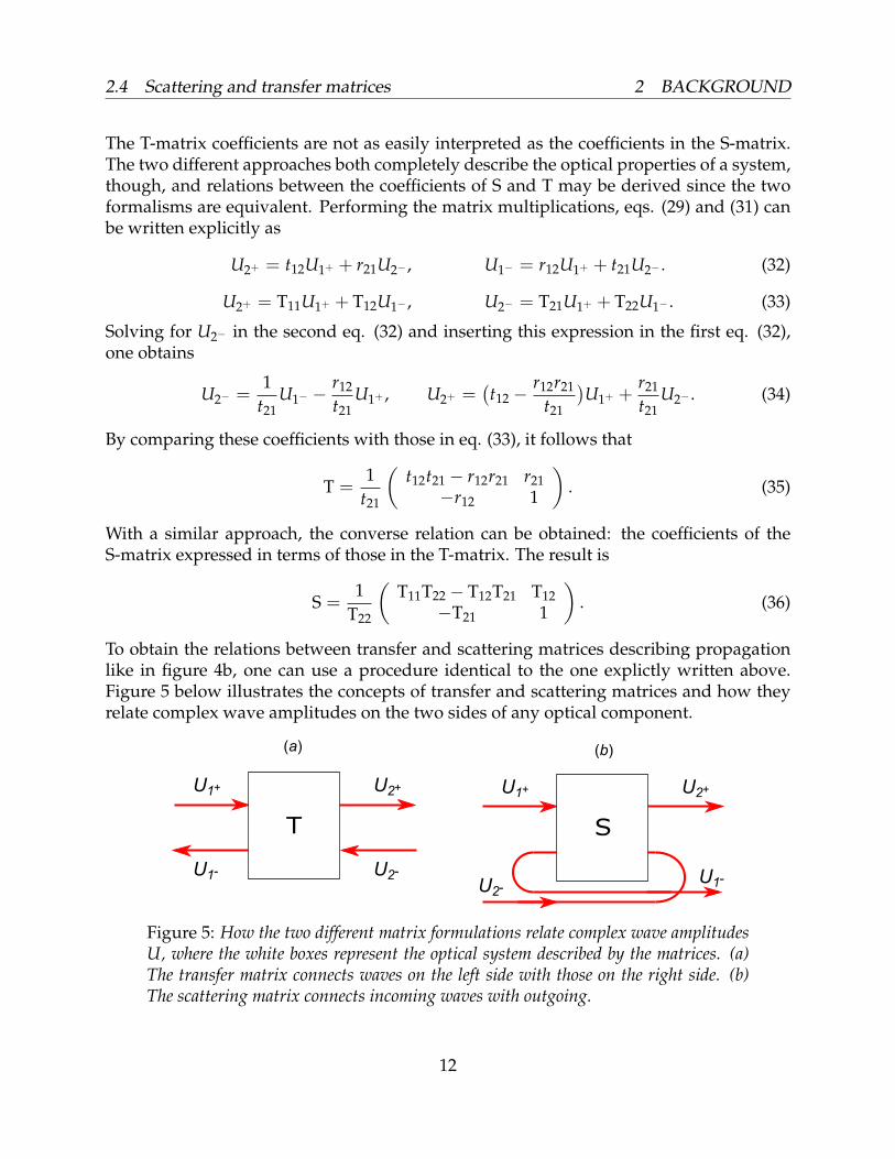
To obtain the relations between transfer and scattering matrices describing propagationlike in figure 4b, one can use a procedure identical to the one explictly written above.Figure 5 below illustrates the concepts of transfer and scattering matrices and how theyrelate complex wave amplitudes on the two sides of any optical component.
Figure 5: How the two different matrix formulations relate complex wave amplitudesU, where the white boxes represent the optical system described by the matrices. (a)The transfer matrix connects waves on the left side with those on the right side. (b)The scattering matrix connects incoming waves with outgoing.
12
2.5 The transfer matrix method 2 BACKGROUND
2.5 The transfer matrix methodTo analyze a multilayer structure, one can set up a scattering matrix to characterize everylayer and boundary. The desired goal is of course to determine the transmission andreflection coefficients for the entire structure. To do this, all of the individual scatteringmatrices need to somehow be combined into a single one. Since a scattering matrix doesnot explicitly relate the left and right hand sides, it is not possible to simply multiply theindividual matrices together to get the total matrix. It seems to be possible to combinethem with the so called Redheffer star product [12], but this procedure is complicatedand non-intuitive. On the other hand, multiple transfer matrices can be combined usingordinary matrix multiplication. To demonstrate this, consider the case of a boundary withvacuum to the left and a medium with refractive index n and thickness d on the right.There are then three pairs of right and left-going waves, UL, UR and Ud to the left, rightand at distance d from the boundary respectively. The optical properties of the boundaryand material are then determined by the matrices T1 and T2 so that(
UR+
UR−
)= T1
(UL+
UL−
),
(Ud+
Ud−
)= T2
(UR+
UR−
). (37)
By inserting the expression for UR from the first equation into the second, we obtain(Ud+
Ud−
)= T2T1
(UL+
UL−
). (38)
Thus the matrix Ttot = T2T1 is a complete description of the composite optical system. Itis easy to generalize this result to apply for N transfer matrices. In that case we get(
UN+
UN−
)= TNTN−1 · · · T2T1
(U1+
U1−
). (39)
Putting everything together one can conclude that if d and n of every layer is known,there is a completely general procedure to find the total Fresnel coefficients. Start by de-termining the Fresnel coefficients for every boundary and the phase ϕ for the propagationbetween the boundaries. This is equivalent to determining the S-matrices. Then use eq.(35) to convert them into T-matrices in order to exploit the multiplicative property im-plied in eq. (39). After having carried out the multiplication, use eq. (36) to convert theresulting T-matrix to the S-matrix for the entire structure. The optical properties of themultilayer are thereby obtained. The procedure outlined above is in this thesis referred toas the transfer matrix method (TMM) and can be used to model propagation through anykind of multilayer optics.
2.6 Dielectric mirrorsIf a mirror is to reflect an ultrashort pulse well, its reflectance must of course be very highover the entire bandwidth of the pulse. For a pulse with a FWHM of 10 fs in the time
13
2.6 Dielectric mirrors 2 BACKGROUND
domain and carrier wavelength λ0 = 800 nm, the bandwidth FWHM is almost 200 nm.In order for most of the pulse to be reflected, the region of high reflectance in frequencyspace must thus be much wider than this. One can obtain a rather high reflectance acrosssuch a bandwidth using a mirror in the form of a thin sheet of metal such as silver orgold. This is the common type of mirror used in almost any type of optical setup. An-other advantage with such metallic mirrors is that since there is no propagation througha dispersive material, the pulse shape remains essentially the same after reflection. How-ever, the reflectance is not high enough for many ultrashort pulse applications: it is hardto achieve a power reflection coefficient larger than 99 % [13]. A pulse of short durationmeans a very high peak intensity, and the small fraction of absorbed light may very wellbe enough to significantly heat the thin metallic layer. The damage caused by this caneither change the optical properties of the mirror in an undesired way or even completelydestroy it. Other mirror designs must thus be considered for the short, high-intensitypulses used in modern femtosecond Ti:sapphire laser systems.
2.6.1 The Bragg reflector
A reflectance much higher than 99 % can be obtained using a stack of dielectrics with lay-ers of alternating refractive index. The low index layers l usually have nl ≈ 1.5 while thehigh index layers h have nh ≈ 2.5− 3: common materials are silicon dioxide (SiO2) andtitanium dioxide (TiO2) respectively. At the value of nh/nl for these materials, the Fresnelreflectance at each boundary is not very high as demonstrated in figure 3. The reflec-tions at all boundaries will however add up with the result being that the total reflectancegrows quickly with the number of layers in the stack.
The layer thickness d is an important parameter since it determines how much phase apropagating wave acquires. A dielectric mirror of the kind discussed above will not workas well if the reflected waves are out of phase with each other and interfere destructively.Maximum reflection will occur when the optical thickness nd is equal to a quarter of thelight wavelength. In this case all reflected waves will interfere constructively which canbe understood as follows. If the reflection occurs from a low-index medium the phaseshift is π. The light incident on this boundary has aquired a phase of π/2 from propaga-tion before reflection, and acquires this same phase after reflection as well: it adds up to aphase of 2π, exactly one wavelength. Light reflected from the previous and next bound-ary is internally reflected and is thus not phase shifted in the reflection process. Thesethree reflected waves will then all have the desired phase difference of an integer numberof 2π and by extension this is true for all reflected waves. Such a mirror is called a Braggreflector since the condition for constructive interference is similar to the famous Bragg’slaw describing the scattering of X-rays off of a crystal lattice. The temporal effects such amirror has on an ultrashort pulse are extensively studied in this thesis.
2.6.2 More complex designs
A short pulse is very sensitive to the group delay variations induced by propagationthrough even a short distance in a dispersive dielectric. It should however be possible to
14
3 METHOD
modify the structure of a thin Bragg reflector slightly so that the reflected pulse exhibitsa certain GD variation profile. Therefore a dielectric mirror might be used to compensatefor GD variations in the incident pulse. The most basic way to do this is to vary the opticalthickness with the layer depth. Thereby the different spectral constituents in the pulseare maximally reflected at different mirror depths, which clearly introduces a GDD. Suchmirror designs are usually referred to as chirped in analogy with the previously discussedconcept of frequency chirp. It is not trivial to determine just how the mirror shall bechirped for a certain GD variation profile to be obtained: the problem is often solvedusing numerical optimization instead of being deduced by principle.
2.6.3 Manufacturing techniques
Since the layers must be very thin (on the order of hundreds of nanometers for visiblelight) for the Bragg condition to be satisfied it is not so easy to actually fabricate a dielec-tric mirror. The thickness of only some thousand atoms per layer also makes the mirrorprone to deposition irregularities at the layer boundaries. Such manufacturing errors mayinduce significant undesired effects like diffuse reflection, resulting in a spatial spread ofthe pulse. It is therefore crucial to use a deposition method with very high precision. Var-ious procedures are available: some commonly used ones are electron beam deposition,ion-assisted deposition and ion beam sputtering [14]. Via such procedures, multilayer op-tics can be produced whose reflection characteristics agree well with theoretical results.
3 Method3.1 General descriptionThe basic idea behind the analysis framework used in this thesis is to combine the TMMwith the FFT in the programming language MATLAB. In the version of the TMM de-scribed in section 2.5 it is assumed that the input wave is monochromatic. This approachcan also be used to model a pulse since a pulse is a linear combination of plane waves.However, every frequency component has to be sent through an individual TMM-routinesince the mirror materials are dispersive. The entire procedure from input pulse to re-flected pulse is described below.
The complex electric field amplitude U0(t) of the input pulse is defined and discretizedin temporal space in MATLAB. It is then Fourier transformed using FFT into frequencyspace so that U0(ω) is obtained. Frequency components that have an intensity |U0(ω)|2larger than a certain value are then selected: these are the plane waves for which the TMMshall be applied. This selection is done since components of very low amplitude barelyaffects the shape of the pulse, and so these can be neglected. Now the refractive indicesn(ω) for the mirror materials must to be obtained. They are needed since they are crucialfor determining the reflection and propagation S-matrices: every frequency componentmust acquire the correct reflection coefficients and propagation phase ϕ = nk0d. At thisstage the mirror structure must be decided upon: the amount of layers and the thickness
15
3.2 The input pulse 3 METHOD
d of every layer is chosen. The Fresnel equations are used to find the coefficients of allboundary S-matrices. When they are determined, the TMM is applied for every selectedfrequency by for-looping through all frequencies. The desired complex reflectance r12 =r(ω) is obtained from the total T-matrix: r(ω) = −T21(ω)/T22(ω).
Now it is known how each complex wave constituting the selected input pulse is affectedby the reflection. This is equivalent to knowing how the pulse itself is affected. We getthe reflected pulse U(ω) in frequency domain by simple element-wise multiplication:U(ω) = r(ω)U0(ω). The mirror thus acts as a frequency domain filter. To evaluate thetemporal properties of the reflected pulse the inverse FFT (IFFT) in MATLAB is used toobtain U(t) from U(ω).
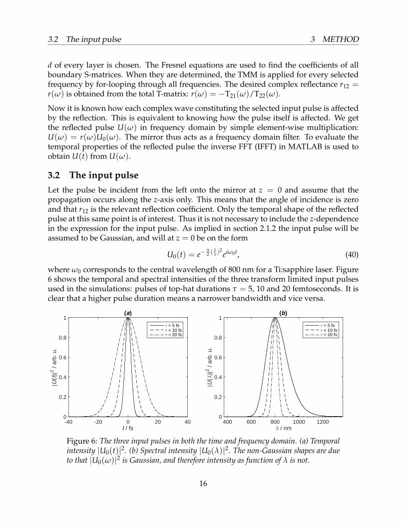
3.2 The input pulseLet the pulse be incident from the left onto the mirror at z = 0 and assume that thepropagation occurs along the z-axis only. This means that the angle of incidence is zeroand that r12 is the relevant reflection coefficient. Only the temporal shape of the reflectedpulse at this same point is of interest. Thus it is not necessary to include the z-dependencein the expression for the input pulse. As implied in section 2.1.2 the input pulse will beassumed to be Gaussian, and will at z = 0 be on the form
U0(t) = e−π2 (
tτ )
2eiω0t, (40)
where ω0 corresponds to the central wavelength of 800 nm for a Ti:sapphire laser. Figure6 shows the temporal and spectral intensities of the three transform limited input pulsesused in the simulations: pulses of top-hat durations τ = 5, 10 and 20 femtoseconds. It isclear that a higher pulse duration means a narrower bandwidth and vice versa.
t / fs-40 -20 0 20 40
|U(t
)|2 /
arb.
u.
0
0.2
0.4
0.6
0.8
1(a)
τ = 5 fsτ = 10 fsτ = 20 fs
λ / nm400 600 800 1000 1200
|U(λ
)|2 /
arb.
u.
0
0.2
0.4
0.6
0.8
1(b)
τ = 5 fsτ = 10 fsτ = 20 fs
Figure 6: The three input pulses in both the time and frequency domain. (a) Temporalintensity |U0(t)|2. (b) Spectral intensity |U0(λ)|2. The non-Gaussian shapes are dueto that |U0(ω)|2 is Gaussian, and therefore intensity as function of λ is not.
16
3.3 Refractive indices and mirror designs 3 METHOD
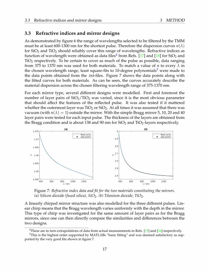
3.3 Refractive indices and mirror designsAs demonstrated by figure 6 the range of wavelengths selected to be filtered by the TMMmust be at least 600-1300 nm for the shortest pulse. Therefore the dispersion curves n(λ)for SiO2 and TiO2 should reliably cover this range of wavelengths. Refractive indices asfunction of wavelength were obtained as data files4 from Refs. [17] and [18] for SiO2 andTiO2 respectively. To be certain to cover as much of the pulse as possible, data rangingfrom 375 to 1370 nm was used for both materials. To match a value of n to every λ inthe chosen wavelength range, least square-fits to 10-degree polynomials5 were made tothe data points obtained from the .txt-files. Figure 7 shows the data points along withthe fitted curves for both materials. As can be seen, the curves accurately describe thematerial dispersion across the chosen filtering wavelength range of 375-1370 nm.
For each mirror type, several different designs were modelled. First and foremost thenumber of layer pairs of SiO2/TiO2 was varied, since it is the most obvious parameterthat should affect the features of the reflected pulse. It was also tested if it matteredwhether the outermost layer was TiO2 or SiO2. At all times it was assumed that there wasvacuum (with n(λ) = 1) outside the mirror. With the simple Bragg mirror 5, 10, 20 and 40layer pairs were tested for each input pulse. The thickness of the layers are obtained fromthe Bragg condition and is about 138 and 90 nm for SiO2 and TiO2-layers respectively.
λ / nm400 600 800 1000 1200
n
1.445
1.45
1.455
1.46
1.465
1.47
1.475(a)
fitted curvedata points
λ / nm400 600 800 1000 1200
n
2.4
2.5
2.6
2.7
2.8
2.9
3(b)
fitted curvedata points
Figure 7: Refractive index data and fit for the two materials constituting the mirrors.(a) Silicon dioxide (fused silica), SiO2. (b) Titanium dioxide, TiO2.
A linearly chirped mirror structure was also modelled for the three different pulses. Lin-ear chirp means that the Bragg wavelength varies uniformly with the depth in the mirror.This type of chirp was investigated for the same amount of layer pairs as for the Braggmirrors, since one can then directly compare the similarities and differences between thetwo designs.
4These are in turn extrapolations of data from actual measurements in Refs. [15] and [16] respectively.5This is the highest order supported by MATLABs ”basic fitting” and was deemed satisfactory as sup-
ported by the very good fits shown in figure 7.
17
3.4 Evaluating the results 4 RESULTS AND DISCUSSION
3.4 Evaluating the resultsSeveral parameters are employed to describe the reflected pulse. Two of these measuresreflectance. They are the mirror reflectivity R(λ) = |r(λ)|2 which is plotted, and theintegrated power reflectance Rtot for the pulse given by
Rtot =
∫ ωmaxωmin
I(ω)dω∫ ωmaxωmin
I0(ω)dω, (41)
where ωmin and ωmax are the frequencies delimiting the filtering range. Rtot is calculatedfor the different designs, as is the ratio of temporal peak intensities Rmax = I(t)max/I0(t)max.
The value of Rmax indicates how much the pulse is smeared out in the time domain.Several other parameters describe how the temporal shape of the pulse is affected bythe mirror. Among them is the accumulated phase ϕ(λ), which determines how muchthe different frequencies in the pulse have been delayed. More specifically it determinesthe GD and the GDD given by the first and second derivative of ϕ(ω) respectively. TheGD is plotted across the range of filtered wavelengths for some selected mirror designs.Also plotted is the electric field E(t) = <[U(t)] for these designs which provides a directmeasure of what the pulse looks like in the time domain after reflection.
4 Results and discussion
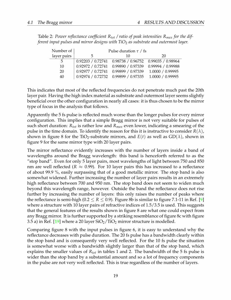
4.1 The Bragg mirrorReflection properties of the eight different Bragg mirrors and the three input pulses thatwere modelled are summarized in tables 1 and 2 on the format [Rtot/Rmax]. In the mirrortypes represented by table 1 both the substrate and outermost layer was SiO2 while itwas TiO2 for the mirror types in table 2. It is clear that the longer pulses are reflected
Table 1: Power reflectance coefficient Rtot / ratio of peak intensities Rmax for the dif-ferent input pulses and mirror designs with SiO2 as substrate and outermost layer.
Pulse duration τ / fsNumber oflayer pairs 5 10 20
5 0.90244 / 0.70772 0.96230 / 0.94685 0.96697 / 0.9656910 0.92948 / 0.70789 0.99870 / 0.97432 0.99980 / 0.9997420 0.92963 / 0.70789 0.99899 / 0.97433 1.0000 / 0.9999840 0.92968 / 0.70798 0.99899 / 0.97437 1.0000 / 0.99998
better than shorter ones regardless of the number of layers or mirror type used. Also, Rtotand Rmax both increase rapidly with the layer number for τ = 10 and 20 fs but not asrapidly for the shortest pulse. The rate of increase also decreases at high layer numbers:the difference is generally larger going from 5 to 10 layer pairs than going from 20 to 40.
18
4.1 The Bragg mirror 4 RESULTS AND DISCUSSION
Table 2: Power reflectance coefficient Rtot / ratio of peak intensities Rmax for the dif-ferent input pulses and mirror designs with TiO2 as substrate and outermost layer.
Pulse duration τ / fsNumber oflayer pairs 5 10 20
5 0.92203 / 0.72741 0.98738 / 0.96752 0.99035 / 0.9896410 0.92972 / 0.72741 0.99890 / 0.97339 0.99994 / 0.9998820 0.92977 / 0.72741 0.99899 / 0.97339 1.0000 / 0.9999540 0.92974 / 0.72732 0.99899 / 0.97335 1.0000 / 0.99995
This indicates that most of the reflected frequencies do not penetrate much past the 20thlayer pair. Having the high index material as substrate and outermost layer seems slightlybeneficial over the other configuration in nearly all cases: it is thus chosen to be the mirrortype of focus in the analysis that follows.
Apparently the 5 fs pulse is reflected much worse than the longer pulses for every mirrorconfiguration. This implies that a simple Bragg mirror is not very suitable for pulses ofsuch short duration: Rtot is rather low and Rmax even lower, indicating a smearing of thepulse in the time domain. To identify the reason for this it is instructive to consider R(λ),shown in figure 8 for the TiO2-substrate mirrors, and E(t) as well as GD(λ), shown infigure 9 for the same mirror type with 20 layer pairs.
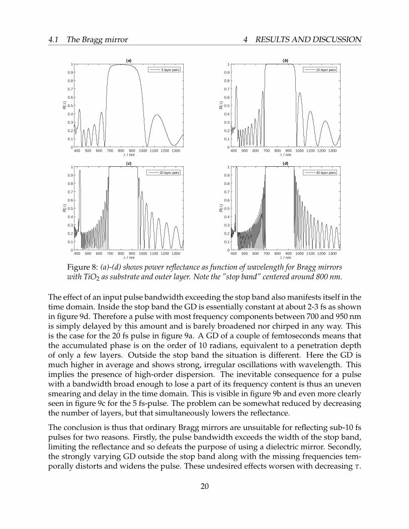
The mirror reflectance evidently increases with the number of layers inside a band ofwavelengths around the Bragg wavelength: this band is henceforth referred to as the”stop band”. Even for only 5 layer pairs, most wavelengths of light between 750 and 850nm are well reflected (R ≈ 0.99). For 10 layer pairs this has increased to a reflectanceof about 99.9 %, easily surpassing that of a good metallic mirror. The stop band is alsosomewhat widened. Further increasing the number of layer pairs results in an extremelyhigh reflectance between 700 and 950 nm. The stop band does not seem to widen muchbeyond this wavelength range, however. Outside the band the reflectance does not risefurther by increasing the number of layers: this only raises the number of peaks wherethe reflectance is semi-high (0.2 ≤ R ≤ 0.9). Figure 8b is similar to figure 7.1-11 in Ref. [9]where a structure with 10 layer pairs of refractive indices of 1.5/3.5 is used. This suggeststhat the general features of the results shown in figure 8 are what one could expect fromany Bragg mirror. It is further supported by a striking resemblance of figure 8c with figure3.5 a) in Ref. [19] where a 20 layer SiO2/TiO2 mirror structure is modelled.
Comparing figure 8 with the input pulses in figure 6, it is easy to understand why thereflectance decreases with pulse duration. The 20 fs pulse has a bandwidth clearly withinthe stop band and is consequently very well reflected. For the 10 fs pulse the situationis somewhat worse with a bandwidth slightly larger than that of the stop band, whichexplains the smaller values of Rtot in tables 1 and 2. The bandwidth of the 5 fs pulse iswider than the stop band by a substantial amount and so a lot of frequency componentsin the pulse are not very well reflected. This is true regardless of the number of layers.
19
4.1 The Bragg mirror 4 RESULTS AND DISCUSSION
λ / nm400 500 600 700 800 900 1000 1100 1200 1300
R(λ
)
0
0.1
0.2
0.3
0.4
0.5
0.6
0.7
0.8
0.9
1(a)
5 layer pairs
λ / nm400 500 600 700 800 900 1000 1100 1200 1300
R(λ
)
0
0.1
0.2
0.3
0.4
0.5
0.6
0.7
0.8
0.9
1(b)
10 layer pairs
λ / nm400 500 600 700 800 900 1000 1100 1200 1300
R(λ
)
0
0.1
0.2
0.3
0.4
0.5
0.6
0.7
0.8
0.9
1(c)
20 layer pairs
λ / nm400 500 600 700 800 900 1000 1100 1200 1300
R(λ
)
0
0.1
0.2
0.3
0.4
0.5
0.6
0.7
0.8
0.9
1(d)
40 layer pairs
Figure 8: (a)-(d) shows power reflectance as function of wavelength for Bragg mirrorswith TiO2 as substrate and outer layer. Note the ”stop band” centered around 800 nm.
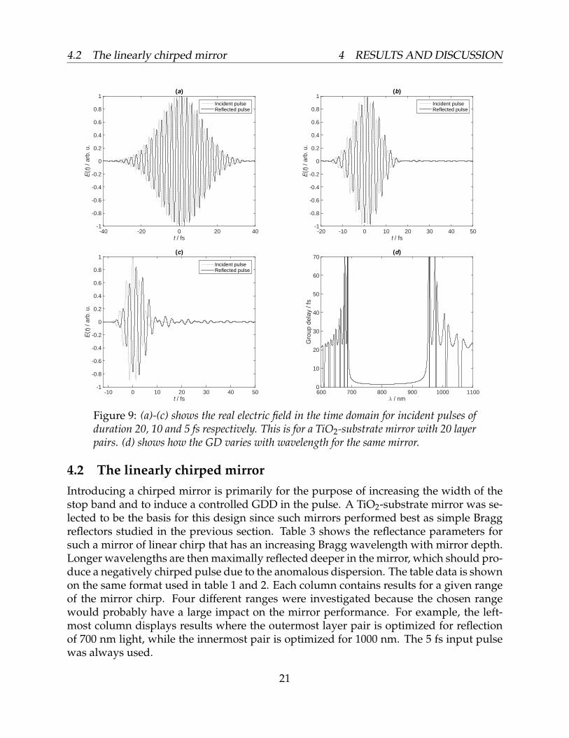
The effect of an input pulse bandwidth exceeding the stop band also manifests itself in thetime domain. Inside the stop band the GD is essentially constant at about 2-3 fs as shownin figure 9d. Therefore a pulse with most frequency components between 700 and 950 nmis simply delayed by this amount and is barely broadened nor chirped in any way. Thisis the case for the 20 fs pulse in figure 9a. A GD of a couple of femtoseconds means thatthe accumulated phase is on the order of 10 radians, equivalent to a penetration depthof only a few layers. Outside the stop band the situation is different. Here the GD ismuch higher in average and shows strong, irregular oscillations with wavelength. Thisimplies the presence of high-order dispersion. The inevitable consequence for a pulsewith a bandwidth broad enough to lose a part of its frequency content is thus an unevensmearing and delay in the time domain. This is visible in figure 9b and even more clearlyseen in figure 9c for the 5 fs-pulse. The problem can be somewhat reduced by decreasingthe number of layers, but that simultaneously lowers the reflectance.
The conclusion is thus that ordinary Bragg mirrors are unsuitable for reflecting sub-10 fspulses for two reasons. Firstly, the pulse bandwidth exceeds the width of the stop band,limiting the reflectance and so defeats the purpose of using a dielectric mirror. Secondly,the strongly varying GD outside the stop band along with the missing frequencies tem-porally distorts and widens the pulse. These undesired effects worsen with decreasing τ.
20
4.2 The linearly chirped mirror 4 RESULTS AND DISCUSSION
t / fs-40 -20 0 20 40
E(t
) / a
rb. u
.
-1
-0.8
-0.6
-0.4
-0.2
0
0.2
0.4
0.6
0.8
1(a)
Incident pulseReflected pulse
t / fs-20 -10 0 10 20 30 40 50
E(t
) / a
rb. u
.
-1
-0.8
-0.6
-0.4
-0.2
0
0.2
0.4
0.6
0.8
1(b)
Incident pulseReflected pulse
t / fs-10 0 10 20 30 40 50
E(t
) / a
rb. u
.
-1
-0.8
-0.6
-0.4
-0.2
0
0.2
0.4
0.6
0.8
1(c)
Incident pulseReflected pulse
λ / nm600 700 800 900 1000 1100
Gro
up d
elay
/ fs
0
10
20
30
40
50
60
70(d)
Figure 9: (a)-(c) shows the real electric field in the time domain for incident pulses ofduration 20, 10 and 5 fs respectively. This is for a TiO2-substrate mirror with 20 layerpairs. (d) shows how the GD varies with wavelength for the same mirror.
4.2 The linearly chirped mirrorIntroducing a chirped mirror is primarily for the purpose of increasing the width of thestop band and to induce a controlled GDD in the pulse. A TiO2-substrate mirror was se-lected to be the basis for this design since such mirrors performed best as simple Braggreflectors studied in the previous section. Table 3 shows the reflectance parameters forsuch a mirror of linear chirp that has an increasing Bragg wavelength with mirror depth.Longer wavelengths are then maximally reflected deeper in the mirror, which should pro-duce a negatively chirped pulse due to the anomalous dispersion. The table data is shownon the same format used in table 1 and 2. Each column contains results for a given rangeof the mirror chirp. Four different ranges were investigated because the chosen rangewould probably have a large impact on the mirror performance. For example, the left-most column displays results where the outermost layer pair is optimized for reflectionof 700 nm light, while the innermost pair is optimized for 1000 nm. The 5 fs input pulsewas always used.
21
4.2 The linearly chirped mirror 4 RESULTS AND DISCUSSION
Table 3: Power reflectance coefficient Rtot / ratio of peak intensities Rmax for the dif-ferent input pulses and chirped mirrors with TiO2 as substrate and outermost layer.
Wavelength range spanned by layer chirp / nmNumber oflayer pairs 700 - 1000 550 - 1100 650 - 1250 600 - 1200
5 0.91281 / 0.70113 0.83760 / 0.39587 0.83455 / 0.65979 0.83923 / 0.5622410 0.98016 / 0.66358 0.96438 / 0.31048 0.96147 / 0.58438 0.96439 / 0.3924920 0.99432 / 0.63462 0.99868 / 0.23744 0.99632 / 0.50899 0.99841 /0.3279340 0.99725 / 0.61959 0.99981 / 0.19447 0.99963/ 0.47514 0.99995 / 0.30993
It is immediately apparent that Rtot is greatly improved upon from the simple Bragg mir-ror, regardless of the wavelength range targeted by the chirp. There are some differences,however. For a small amount of layers it appears to be most efficient to concentrate on thecentral pulse wavelengths. This changes rapidly so that for 20 layer pairs it seems favor-able to focus on the shorter wavelengths. For 40 pairs the design based on encompassingthe entire pulse bandwidth is by far the best in terms of Rtot.
All designs appear to smear the pulse badly in the time domain since Rmax � 1 in allcases. Targeting short wavelengths maximally smears the pulse, while chirping only forcentral wavelengths maintains the initial Imax fairly well. It must be stressed that a lowRmax is not necessarily bad for a chirped mirror, though. Dispersion of some kind isexpected, and an initially transform limited pulse affected by dispersion will inevitablywiden temporally. What is important is rather that the GD varies consistently across thepulse bandwidth, so that only certain orders of dispersion are introduced in the pulse. Itis namely much easier to compensate for dispersion if it is relatively uncomplicated.
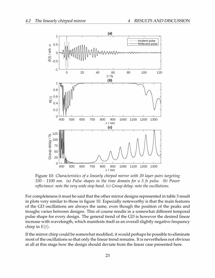
In figure 10 the temporal effects of the design with 20 layer pairs and chirp range of550-1100 nm are illustrated (a) together with the reflectance (b) and GD characteristics(c). As suggested by table 3, the stop band is very wide indeed. Emax (and thereby Imax)is low for the reflected pulse compared to the incident, and the pulse is widened by agreat amount by the mirror. There is some negative chirp, but the irregular pulse shapeimplies many different higher orders of dispersion as well. Consequently, the difficultyof making the pulse transform limited again by dispersion compensation is immenselyhigh. Designing an optical component with the complicated ϕ(λ)-characteristics requiredwould be a nearly hopeless task.
The periodic oscillations in the GD as shown in figure 10c explain the irregular pulseshape in the time domain. Very similar oscillations are seen in figure 3.7 in Ref. [19]where a linearly chirped mirror is modelled. The cause of the oscillations appear to beinterference between reflections in shallow and deep parts of the mirror, like in a so-calledGires-Tournois interferometer (GTI). The oscillations were first observed in 1985 [20] andnot studied in detail as GTI-like effects until in 1999 [19]. To conclude: the naive expecta-tion of a GD varying linearly with the wavelength is wrong and the simple chirped mirrorwould be useless inside a Ti:sapphire laser cavity or in an external pulse-shaping setup.
22
4.2 The linearly chirped mirror 4 RESULTS AND DISCUSSION
t / fs0 20 40 60 80 100 120
E(t
) / a
rb. u
.
-1
-0.5
0
0.5
1(a)
Incident pulseReflected pulse
λ / nm400 500 600 700 800 900 1000 1100 1200 1300
R(λ
)
0
0.2
0.4
0.6
0.8
1(b)
λ / nm400 500 600 700 800 900 1000 1100 1200 1300
Gro
up d
elay
/ fs
0
25
50
75
100
125
(c)
Figure 10: Characteristics of a linearly chirped mirror with 20 layer pairs targeting550 - 1100 nm. (a) Pulse shapes in the time domain for a 5 fs pulse. (b) Powerreflectance: note the very wide stop band. (c) Group delay: note the oscillations.
For completeness it must be said that the other mirror designs represented in table 3 resultin plots very similar to those in figure 10. Especially noteworthy is that the main featuresof the GD oscillations are always the same, even though the position of the peaks andtroughs varies between designs. This of course results in a somewhat different temporalpulse shape for every design. The general trend of the GD is however the desired linearincrease with wavelength, which manifests itself as an overall slightly negative frequencychirp in E(t).
If the mirror chirp could be somewhat modified, it would perhaps be possible to eliminatemost of the oscillations so that only the linear trend remains. It is nevertheless not obviousat all at this stage how the design should deviate from the linear case presented here.
23
4.3 Accuracy of the simulations 4 RESULTS AND DISCUSSION
4.3 Accuracy of the simulationsWhat matters in the end is of course that actual fabricated dielectric mirrors exhibit thedesired reflection properties demonstrated in section 4.1 and 4.2. The easiest way to in-vestigate the accuracy of the TMM-based model in this thesis would of course be to man-ufacture one of the simulated designs using one of the techniques mentioned in section2.6.3. Unfortunately this was beyond the scope of the thesis work. Models similar to thisone are used by many research groups to simulate multilayers, though, and very oftenthe obtained results seem to be in good agreement with experimental realizations. This isshown for example by figure 4 in Ref. [21]. Using a model which incorporates the bulkparameter that is the refractive index therefore appears to work well even if each mirrorlayer is only a couple of hundred atoms thick. It must be noted that the agreement withfabricated mirrors depend a lot on the manufacturing process. The refractive index canvary greatly with for example the pressure and temperature used.
The precision of the specific numerical model used here remains to be assessed. One ofits advantages is that it takes into account the frequency dependence of n, thereby mod-elling the reflectivity and phase for every single frequency component more accuratelycompared to models which do not. Especially TiO2 exhibits significant dispersion withinthe relevant wavelength range of 375-1370 nm, and so the benefit of using a unique n forevery wavelength in the pulse is likely to be substantial. The advantage is strengthenedfurther by the very detailed knowledge of the refractive indices across these wavelengthsas is demonstrated in figure 7.
Applying r obtained by the TMM only for wavelengths between 375 and 1370 nm is likelyto have a negative effect on the end results. Even the 20 fs pulse does after all contain spec-tral components outside this range. The amplitudes of these components are, however,very insignificant. At 375 nm the 5 fs pulse has a spectral intensity I0 below a billionthof Imax = I0(λ0) where λ0 = 800 nm. At the other end of the spectrum at 1370 nm thesituation is somewhat worse: I0 for the 5 fs pulse is 1/2000 of Imax, while the 10 and 20fs pulses have values of I0 below a billionth of Imax. The results for the 5 fs pulse areprobably not notably affected by this though: Imax/2000 is still very insignificant. Thewavelength range used is thus concluded to be wide enough to provide a very high ac-curacy for all pulses modelled here. If considering even shorter pulses than in this thesis,it would however be desirable to have access to refractive index data beyond 1370 nm.
When transforming back and forth between the time and frequency domain as done inthis model it is important to have both a high temporal and spectral resolution. This isachieved by having a high sampling rate (or equivalently, a short sampling interval) anda time vector much longer than the pulses themselves. In the MATLAB-code used in thesimulations a total of two million samples were used, spanning from -5000 to +5000 fsresulting in a sampling interval of 5 as. Since GD(λ) never goes higher than about 150 fsfor any of the mirror designs, there should be virtually no observable aliasing effects in thetime domain. This means that there is no noticeable ”false signal” due to the periodicity
24
5 SUMMARY AND OUTLOOK
of the time vector. If the time vector would have been shorter than 150 fs, frequenciesdelayed by more than this amount would instead have appeared as such false signals inthe other end of the time vector.
The conclusion is that the TMM-based method used in this thesis produces accurate re-sults. Optical characteristics exhibited by one of the studied mirror designs manufacturedwith a high-precision technique should thus agree well with the simulations. The methodis also very efficient: it takes only between ten and thirty seconds to run a simulation.
5 Summary and outlookIn this thesis, we have shown that if a Ti:sapphire laser is to be used for generation of 20fs pulses or longer, ordinary Bragg mirrors can be used in the setup since they providethe necessary bandwidth with very high reflectance and an approximately constant GD.Bragg reflectors can for the same reasons also replace conventional mirrors outside thelaser itself to guide the pulse along a desired beam path, with hardly any pulse energyloss or induced group delay variations. For shorter pulse durations a Bragg mirror failsto fulfill these two criteria as has been discussed in section 4.1.
Also shown in the thesis is that the linearly chirped mirror is a double-edged sword. Itdoes exhibit an outstandingly wide stop band resulting in excellent reflectance for evena 5 fs pulse, but its unsatisfactory dispersion profile renders it useless. However, as im-plied in section 4.2 the tendency of the GD to increase linearly with wavelength is of keyinterest. A refinement of the linear chirp design might display only the linear variation,inducing a negative chirp in the reflected pulse. The normal dispersion exhibited by theTi:sapphire crystal can then be compensated for, if the dispersion provided by the mirroris of the same magnitude as that of the crystal. The standard approach is to use a pair ofprisms for dispersion compensation in a Ti:sapphire laser [8]. Since it imposes a negativeGDD, a chirped mirror could replace the prism pair as the down-chirping optical com-ponent in the laser. Such mirrors have been devised via computer optimization, using alinearly chirped mirror like the one studied in section 4.2 as a starting design [22]. Replac-ing the prism pair would be greatly desired since the prisms exhibit substantial amountsof unwanted higher order dispersion which will notably affect very short pulses6. A cor-rectly designed mirror, however, does not.
The solution to the GD oscillation problem is to have an anti-reflection coating on top ofthe mirror structure together with a slight additional chirp in layer thickness, affectinghow strongly a wave incident on a given layer interferes with the wave reflected off ofthat layer. This is called a double-chirped mirror. How such a mirror has to be chirped toachieve a certain desired GD(λ)-curve can been derived analytically [23]: the importantresult is often called the chirp law. This law is not exact: mirror designs based on the
6See figure 3.3 in Ref. [19]
25
5 SUMMARY AND OUTLOOK
chirp law still have to be fine-tuned using numerical optimization. GD(λ) for a givenstarting design determined by the chirp law does not, however, deviate very much fromthe desired dispersion characteristics.
The analytical description of chirped mirrors has resulted in rapid progress: double-chirped mirrors with dispersion curves based on the chirp law are now commerciallyavailable and used in many femtosecond laser systems. New areas of applications forsuch dielectric mirrors have also started to appear as a result of recent advances in at-tosecond science. The pulses generated in the HHG process are often chirped and con-sequently not as short as a transform limited pulse of the same frequency content. Achirped mirror with the opposite GDD of the pulse itself could thus be used to bring thefrequency components together in time, shortening the pulse durations. This has beendone theoretically as reported in a recent paper [24]. These promising results indicatethat the already short pulses could potentially be compressed down to durations of onlytens of attoseconds.
It was stated in section 2.5 that methods based on the transfer matrix method could ”beused to model propagation through any kind of multilayer optics”. The results obtainedfor the mirror designs in section 4 support this claim, and this is further validated forinstance by ref. [25], where a multilayer mirror reflecting an attosecond pulse is modelledemploying a transfer matrix approach combined with FFT. This clearly demonstrates theapplicability and generality of the main analysis framework used in this thesis, whichthus should provide a basis for further studies in the field of ultrafast optics.
AcknowledgementsI would like to thank my supervisor, Per Johnsson, for introducing me to the excitingresearch field of ultrafast science and for the support he has given me during the thesiswork.
Thanks should also go to my classmate Thomas Kjellberg Jensen for the very fruitfuldiscussions we have had during the writing of our theses.
Last but not least: many thanks to the coffeemaker in ”Rydbergs kallare” at Fysicum forits never-ending supply of liquid productivity.
26
References
[1] C. V. Shank and E. P. Ippen. Subpicosecond kilowatt pulses from a mode-locked cwdye laser. Applied Physics Letters, 24(8):373–375, 1974. doi:10.1063/1.1655222.
[2] U. Morgner, F. X. Kartner, S. H. Cho, Y. Chen, H. A. Haus, J. G. Fujimoto, E. P. Ippen,V. Scheuer, G. Angelow, and T. Tschudi. Sub-two-cycle pulses from a Kerr-lens mode-locked Ti:sapphire laser. Optics letters, 24(6):411–413, 1999. doi:10.1364/OL.24.
000920.
[3] Ahmed H. Zewail. Femtochemistry. Past, present, and future. Pure and Applied Chem-istry, 72(12):2219–2231, 2000. doi:10.1351/pac200072122219.
[4] Anne L’Huillier, M. Lewenstein, P. Salieres, Ph. Balcou, M. Yu Ivanov, J. Larsson,and C. G. Wahlstrom. High-order Harmonic-generation cutoff. Physical Review A,48(5):69–72, 1993. doi:10.1103/PhysRevA.48.R3433.
[5] C. G. Wahlstrom, J. Larsson, A. Persson, T. Starczewski, S. Svanberg, P. Salieres, Ph.Balcou, and Anne L’Huillier. High-order harmonic generation in rare gases with anintense short-pulse laser. Physical Review A, 48(6):4709–4720, 1993. doi:10.1103/
PhysRevA.48.4709.
[6] P. Johnsson. Attosecond Optical and Electronic Wave Packets. PhD thesis, Lund Univer-sity, 2006.
[7] Pierre Agostini and Louis F. DiMauro. The physics of attosecond light pulses. Reportson Progress in Physics, 67(8):1563–1563, 2004. doi:10.1088/0034-4885/67/8/C01.
[8] J. Zhou, G. Taft, C. P. Huang, M. M. Murnane, H. C. Kapteyn, and I. P. Christov.Pulse evolution in a broad-bandwidth Ti:sapphire laser. Optics letters, 19(15):1149–1151, 1994. doi:10.1364/OL.19.001149.
[9] B.E.A. Saleh and M.C. Teich. Fundamentals of Photonics. John Wiley & Sons, Inc., 2ndedition, 2007.
[10] John David Jackson. Classical Electrodynamics. John Wiley & Sons, Inc., 3rd edition,1999.
[11] M. N. Polyanskiy. Refractive Index database. Visited 2015-03-05. URL: http://refractiveindex.info.
[12] R. Redheffer. Difference equations and functional equations in transmission-line the-ory. In Modern Mathematics for the Engineer, chapter 12. McGraw-Hill, New York,1961.
[13] R. Paschotta. Metal-coated mirrors, Encyclopedia of Laser Physics and Technology. Vis-ited 2015-04-06. URL: http://www.rp-photonics.com/metal_coated_mirrors.htm.
[14] R. Paschotta. Dielectric Coatings, Encyclopedia of Laser Physics and Technology. Vis-ited 2015-04-06. URL: http://www.rp-photonics.com/encyclopedia_cite.html?article=dielectriccoatings.
[15] I. H. Malitson. Interspecimen Comparison of the Refractive Index of Fused Silica.Journal of the Optical Society of America, 55(10):1205, 1965. doi:10.1364/JOSA.55.
001205.
[16] J. R. Devore. Refractive Indices of Rutile and Sphalerite. Journal of the Optical Societyof America, 41(6):416, 1951. doi:10.1364/JOSA.41.000416.
[17] Refractive Index of SiO2, Filmetrics, Inc. Visited 2015-03-12.URL: http://www.filmetrics.com/refractive-index-database/SiO2/
Fused-Silica-Silica-Silicon-Dioxide-Thermal-Oxide-ThermalOxide.
[18] Refractive Index of TiO2, Filmetrics, Inc. Visited 2015-03-12. URL:http://www.filmetrics.com/refractive-index-database/TiO2+-+Amorphous/
Titanium-Dioxide.
[19] Nicolai Matuschek. Theory and Design of Double-Chirped Mirrors. PhD thesis, SwissFederal Institute of Technology Zurich, 1999.
[20] P. Laporta and V. Magni. Dispersive effects in the reflection of femtosecond opticalpulses from broadband dielectric mirrors. Applied optics, 24(13):2014, 1985. doi:
10.1364/AO.24.002014.
[21] F.X. Kartner, N. Matuschek, T. Schibli, U. Keller, H.A. Haus, C. Heine, R. Morf,V. Scheuer, M. Tilsch, and T. Tschudi. Design and fabrication of double-chirped mir-rors. Optics letters, 22(11):831–833, 1997. doi:10.1364/OL.22.000831.
[22] R. Szipocs, K. Ferencz, C. Spielmann, and F. Krausz. Chirped multilayer coatings forbroadband dispersion control in femtosecond lasers. Optics letters, 19(3):201, 1994.doi:10.1364/OL.19.000201.
[23] Nicolai Matuschek, Franz X. Kartner, and Ursula Keller. Analytical Design ofDouble-Chirped Mirrors with Custom-Tailored Dispersion Characteristics. IEEEJournal of Quantum Electronics, 35(2):129–137, 1999. doi:10.1109/3.740733.
[24] Alexander Guggenmos. Aperiodic multilayer mirrors for attosecond soft x-raypulses. SPIE Optical . . . , 8502(400 mm):1–7, 2012. URL: http://proceedings.
spiedigitallibrary.org/proceeding.aspx?articleid=1382033, doi:10.1117/12.930762.
[25] Cheng-You Lin and Da-He Liu. Reflecting a single attosecond pulse by using peri-odic Mo/Si multilayer mirrors with different layers. Chinese Physics B, 21(9):094216,2012. doi:10.1088/1674-1056/21/9/094216.


![MUlTilayER CERaMiC ChiP CaPaCiTORS Multilayer ... - …€¦ · Series Description Case Size TC and Dielectric Voltage Capacitance [Min. V] [Max. V] [Min.] [Max.] VJ…SE Source Energy](https://img.pdfslide.us/doc/110x75/5b15e3ee7f8b9a961e8bdadc/multilayer-ceramic-chip-capacitors-multilayer-series-description-case.jpg)