Embed Size (px)
Citation preview
New Millennium Building Systems7575 West Jefferson BlvdFort Wayne, IN 46804Tel: 260-969-3500Web: www.newmill.com
©2019 New Millennium Building Systems. The material contained in this course was researched, assembled, and produced by New Millennium Building Systems and remains its property.
Design of Long-Span Composite Steel Deck Slabs
Purpose and Learning Objectives
Purpose: Long-span composite steel deck slabs blend the speed and versatility of steel construction with the performance and durability of concrete, enabling a holistic approach to space-efficient structural designs. They are engineered to reduce story height while maximizing ceiling height and address market-specific building requirements. This course reviews the design criteria for long-span composite steel deck slabs and shows how they can be designed to increase available space, enhance structural performance, and reduce total project costs.
Learning Objectives:At the end of this program, participants will be able to:• identify the components of a composite floor system and explain why a steel deck composite floor system can reduce
costs and provide a simple, efficient, safe method of construction• analyze composite slab design criteria and calculations to show how a span can be increased and meet strength and
deflection requirements without a significant increase to the weight of a slab • reference industry standards and discuss how long-span steel deck composite floor systems can achieve open
structures and comply with sound transmission and floor vibration design criteria (which can dictate occupant comfort) common to residential or commercial construction, and
• evaluate different types of composite deck profiles and recall case studies where long-span composite steel deck slabs have been successfully used in different new and retrofit applications, including parking garages, specialty platforms, and multistory residential, commercial, healthcare, and educational buildings.
INTRODUCTION TO COMPOSITE SLABS
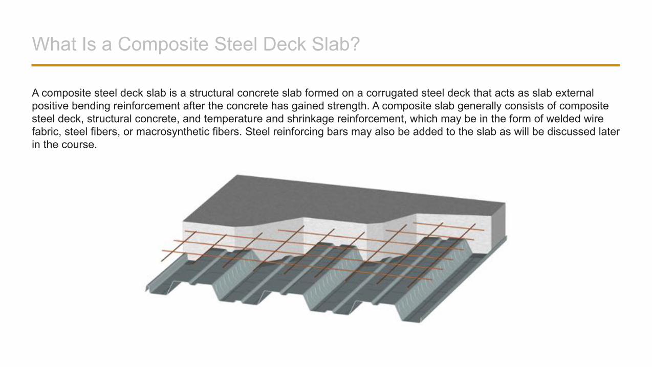
What Is a Composite Steel Deck Slab?
A composite steel deck slab is a structural concrete slab formed on a corrugated steel deck that acts as slab external positive bending reinforcement after the concrete has gained strength. A composite slab generally consists of composite steel deck, structural concrete, and temperature and shrinkage reinforcement, which may be in the form of welded wire fabric, steel fibers, or macrosynthetic fibers. Steel reinforcing bars may also be added to the slab as will be discussed later in the course.
What Is a Composite Steel Deck Slab?
Conventional composite steel deck and composite floor deck slabs are typically used without shoring in steel-framed buildings with relatively short spans. Structural design of such slabs is quite simple using load tables published by deck manufacturers.
The design of long-span composite slabs takes more time and effort, but the extra work is well rewarded in the final result—a modern building with large, open interior spaces. Typically, the building is constructed quickly with significant savings due to the use of long-span composite deck slabs, when the slabs were designed efficiently. The ways of achieving efficient designs of long-span slabs are discussed later in this course.
Main Functions of Steel Deck in Composite Slabs
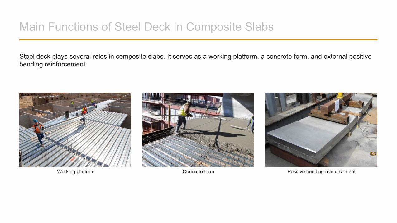
Steel deck plays several roles in composite slabs. It serves as a working platform, a concrete form, and external positive bending reinforcement.
Working platform Concrete form Positive bending reinforcement
Benefits of Composite Steel Deck Slabs
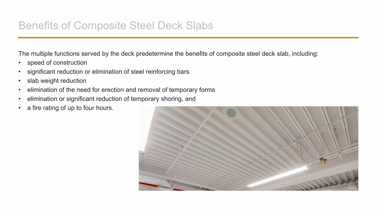
The multiple functions served by the deck predetermine the benefits of composite steel deck slab, including: • speed of construction• significant reduction or elimination of steel reinforcing bars• slab weight reduction• elimination of the need for erection and removal of temporary forms• elimination or significant reduction of temporary shoring, and • a fire rating of up to four hours.
Means of Providing Composite Action
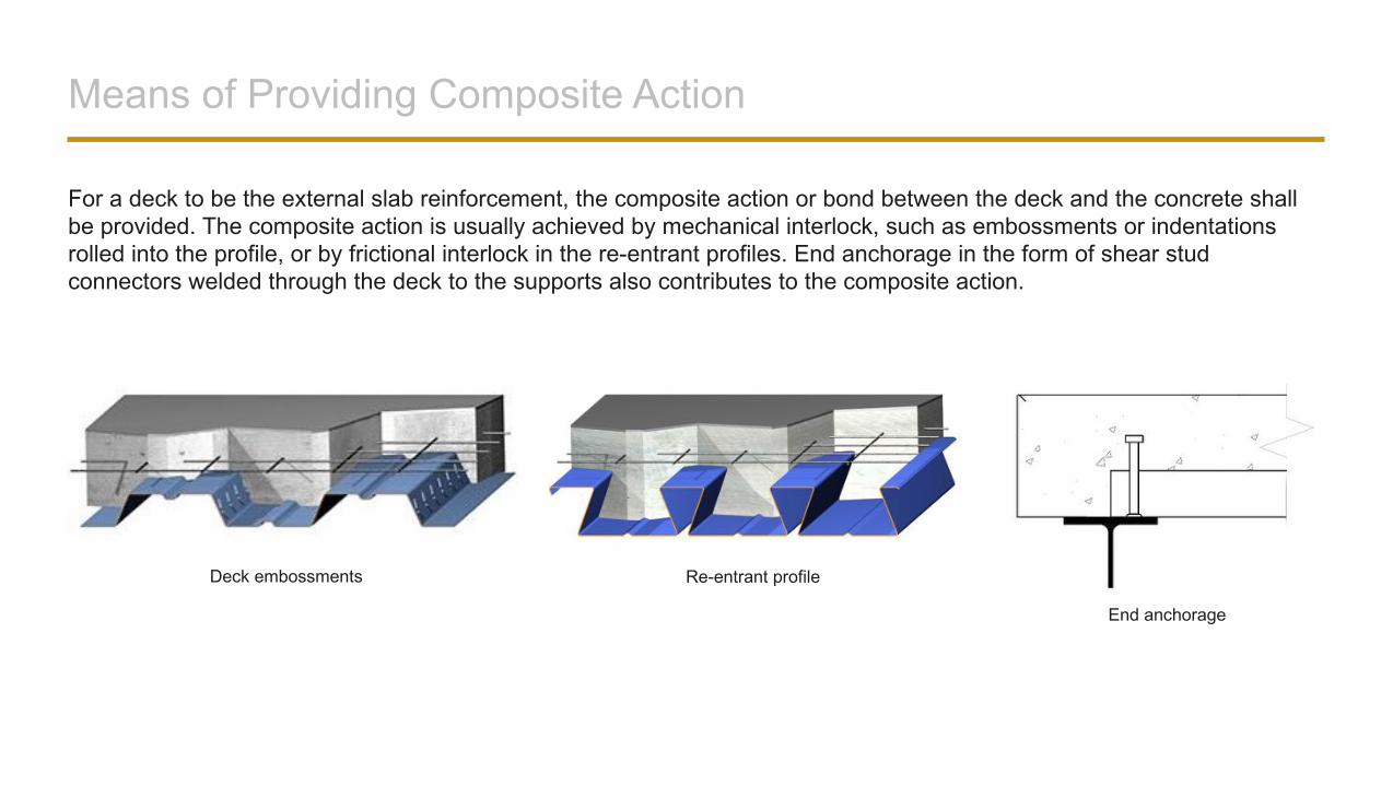
For a deck to be the external slab reinforcement, the composite action or bond between the deck and the concrete shall be provided. The composite action is usually achieved by mechanical interlock, such as embossments or indentations rolled into the profile, or by frictional interlock in the re-entrant profiles. End anchorage in the form of shear stud connectors welded through the deck to the supports also contributes to the composite action.
Deck embossments Re-entrant profile
End anchorage
Composite Deck Types
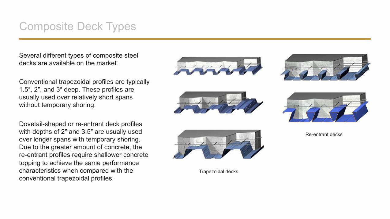
Several different types of composite steel decks are available on the market.
Conventional trapezoidal profiles are typically 1.5″, 2″, and 3″ deep. These profiles are usually used over relatively short spans without temporary shoring.
Dovetail-shaped or re-entrant deck profiles with depths of 2″ and 3.5″ are usually used over longer spans with temporary shoring. Due to the greater amount of concrete, the re-entrant profiles require shallower concrete topping to achieve the same performance characteristics when compared with the conventional trapezoidal profiles.
Trapezoidal decks
Re-entrant decks
Composite Deck Types
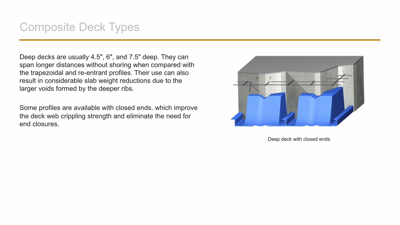
Deep decks are usually 4.5″, 6″, and 7.5″ deep. They can span longer distances without shoring when compared with the trapezoidal and re-entrant profiles. Their use can also result in considerable slab weight reductions due to the larger voids formed by the deeper ribs.
Some profiles are available with closed ends. which improve the deck web crippling strength and eliminate the need for end closures.
Deep deck with closed ends
Composite Deck Types
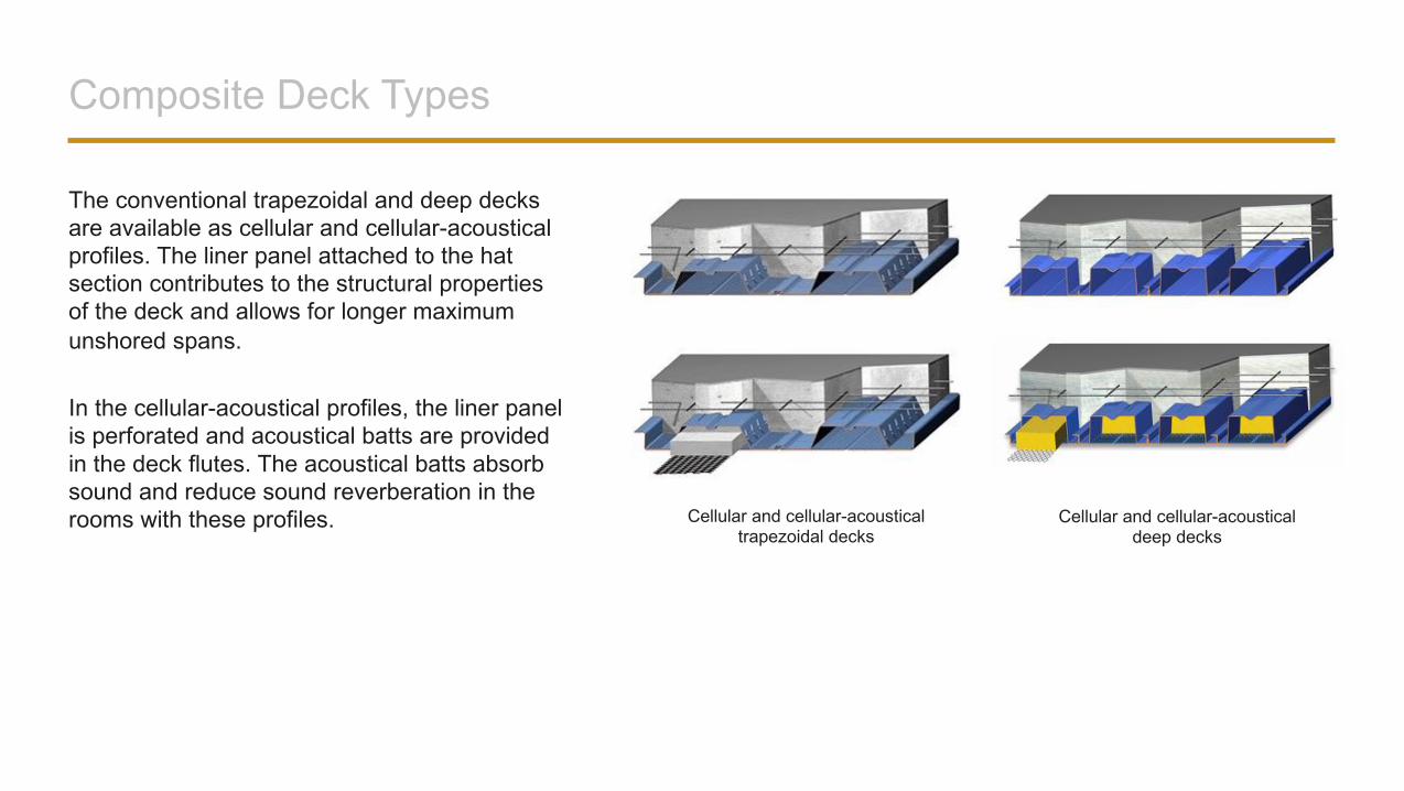
The conventional trapezoidal and deep decks are available as cellular and cellular-acoustical profiles. The liner panel attached to the hat section contributes to the structural properties of the deck and allows for longer maximum unshored spans.
In the cellular-acoustical profiles, the liner panel is perforated and acoustical batts are provided in the deck flutes. The acoustical batts absorb sound and reduce sound reverberation in the rooms with these profiles. Cellular and cellular-acoustical
trapezoidal decksCellular and cellular-acoustical
deep decks
Composite Deck Types
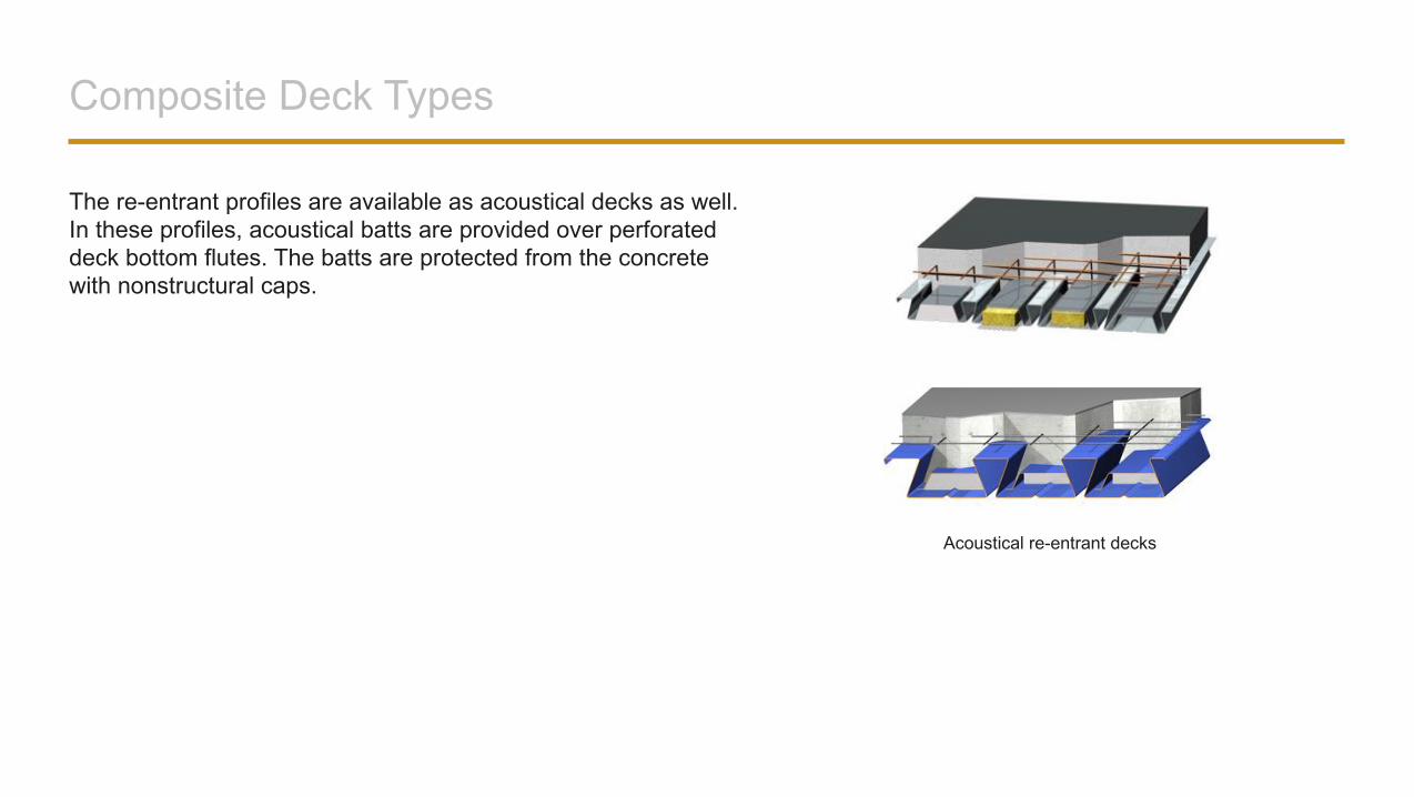
The re-entrant profiles are available as acoustical decks as well. In these profiles, acoustical batts are provided over perforated deck bottom flutes. The batts are protected from the concrete with nonstructural caps.
Acoustical re-entrant decks
COMPOSITE SLAB DESIGN RESOURCES
Design Standards
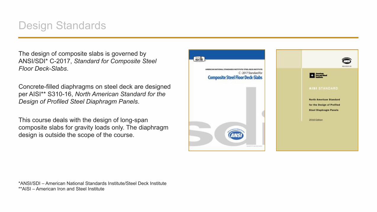
The design of composite slabs is governed by ANSI/SDI* C-2017, Standard for Composite Steel Floor Deck-Slabs.
Concrete-filled diaphragms on steel deck are designed per AISI** S310-16, North American Standard for the Design of Profiled Steel Diaphragm Panels.
This course deals with the design of long-span composite slabs for gravity loads only. The diaphragm design is outside the scope of the course.
*ANSI/SDI – American National Standards Institute/Steel Deck Institute**AISI – American Iron and Steel Institute
SDI Design Manuals
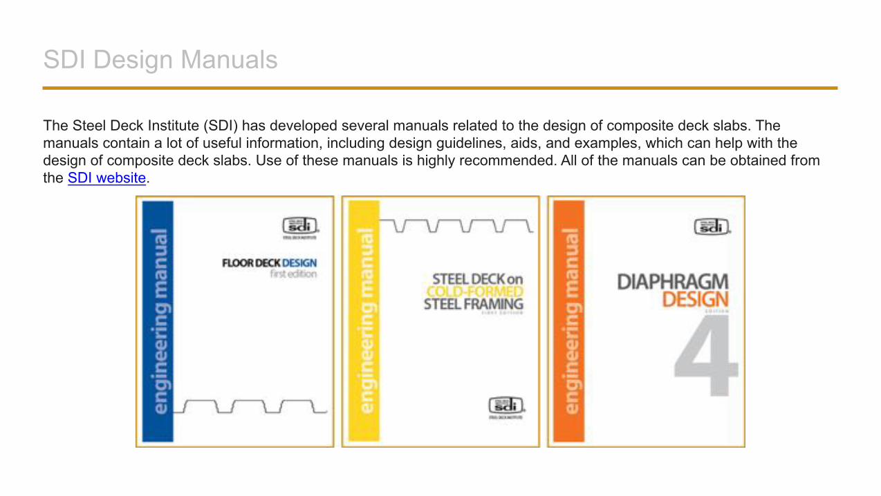
The Steel Deck Institute (SDI) has developed several manuals related to the design of composite deck slabs. The manuals contain a lot of useful information, including design guidelines, aids, and examples, which can help with the design of composite deck slabs. Use of these manuals is highly recommended. All of the manuals can be obtained from the SDI website.
Deck Manufacturer Resources
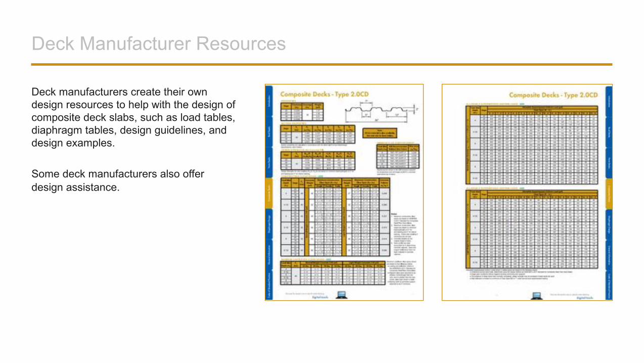
Deck manufacturers create their own design resources to help with the design of composite deck slabs, such as load tables, diaphragm tables, design guidelines, and design examples.
Some deck manufacturers also offer design assistance.
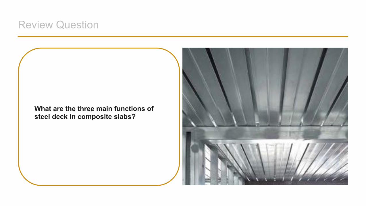
Review Question
What are the three main functions of steel deck in composite slabs?
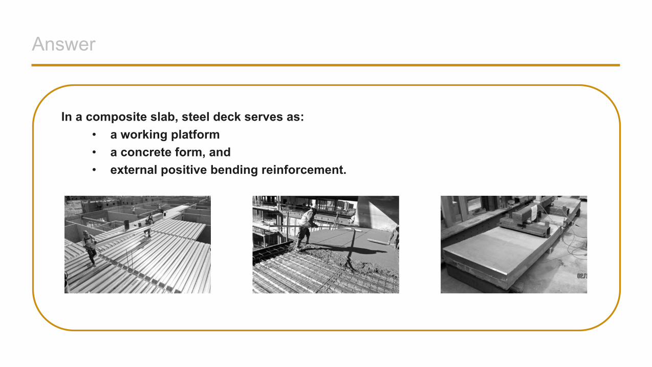
Answer
In a composite slab, steel deck serves as:• a working platform• a concrete form, and• external positive bending reinforcement.
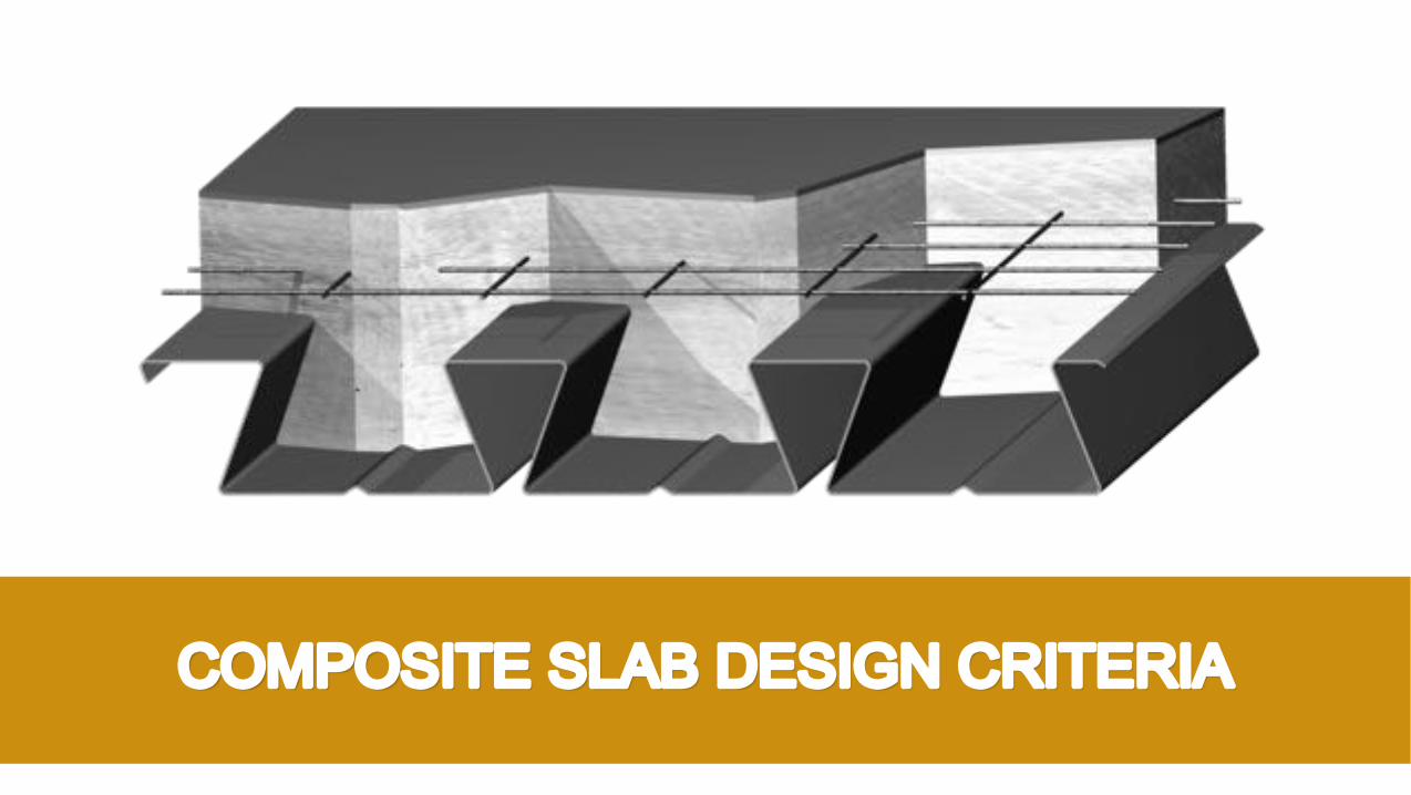
COMPOSITE SLAB DESIGN CRITERIA
Deck as a Form: Strength Requirements
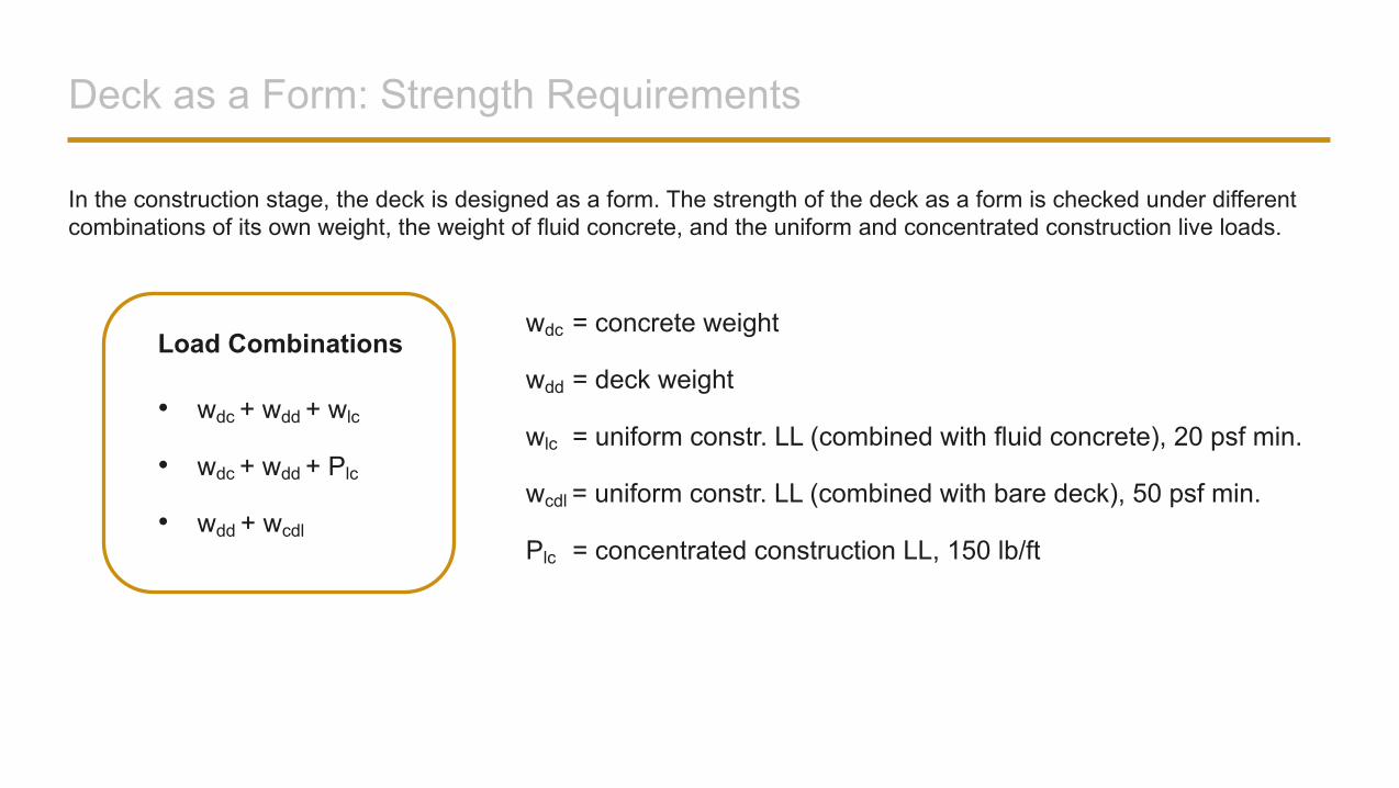
In the construction stage, the deck is designed as a form. The strength of the deck as a form is checked under different combinations of its own weight, the weight of fluid concrete, and the uniform and concentrated construction live loads.
Load Combinations
• wdc + wdd + wlc
• wdc + wdd + Plc
• wdd + wcdl
wdc = concrete weight
wdd = deck weight
wlc = uniform constr. LL (combined with fluid concrete), 20 psf min.
wcdl = uniform constr. LL (combined with bare deck), 50 psf min.
Plc = concentrated construction LL, 150 lb/ft
Deck as a Form: Strength Requirements
Deck section properties and capacities are determined in accordance with AISI S100, North American Specification for the Design of Cold-Formed Steel Structural Members. The applied forces are compared with the deck capacities.
Evaluated deck capacities (determined per AISI S100) include:• positive and negative (for continuous decks) moment capacities• shear capacity and combined moment and shear, and• web crippling capacities at exterior and interior supports.
Steel deck manufacturers usually do these calculations and publish results in the form of maximum unshored clear spans for different deck types, deck gages, slab depths, and concrete densities.
An important thing to keep in mind is the construction live loads that were used for the development of the load tables. ANSI/SDI C-2017 specifies the minimum uniform construction live load of 20 psf when combined with fluid concrete. This load is considered adequate for concrete transport and placement by hose and finishing using hand tools. The maximum unshored clear spans in the deck manufacturer load tables are typically based on this minimum construction load. In actual construction, motorized finishing equipment such as power screeds may be used, which may require design of the deck for higher construction live loads of 50 psf or even greater. Therefore, it is important to have a good understanding ofthe design loads used for calculating maximum unshored spans published in deck load tables, as well as the means and methods of concrete placement used by the contractor.
Deck as a Form: Deflection Requirements
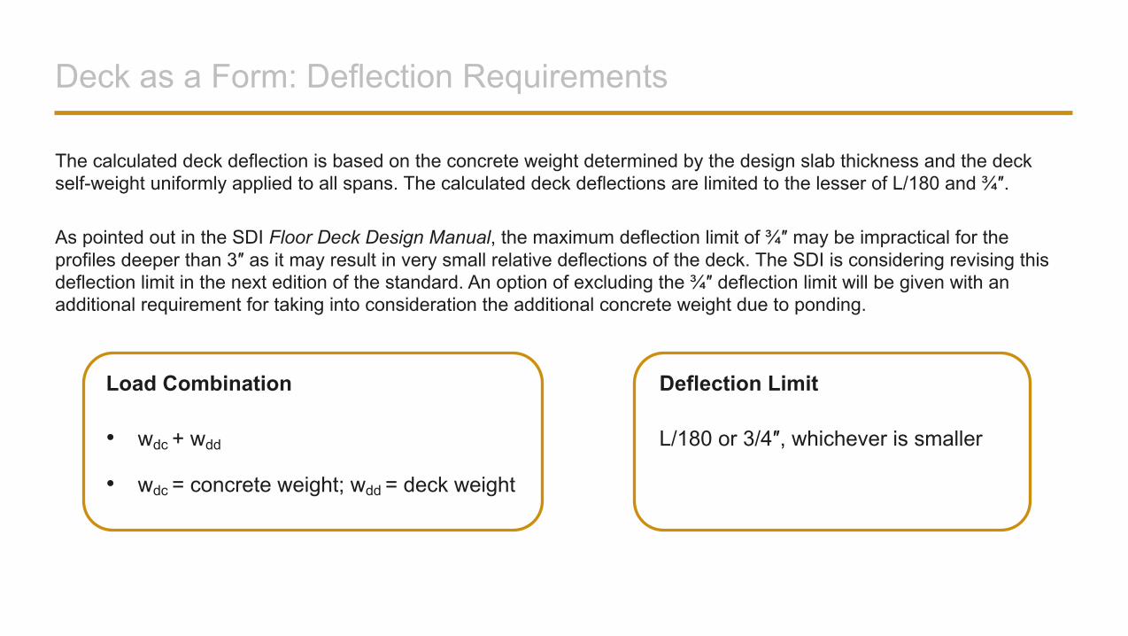
The calculated deck deflection is based on the concrete weight determined by the design slab thickness and the deck self-weight uniformly applied to all spans. The calculated deck deflections are limited to the lesser of L/180 and ¾″.
As pointed out in the SDI Floor Deck Design Manual, the maximum deflection limit of ¾″ may be impractical for the profiles deeper than 3″ as it may result in very small relative deflections of the deck. The SDI is considering revising thisdeflection limit in the next edition of the standard. An option of excluding the ¾″ deflection limit will be given with an additional requirement for taking into consideration the additional concrete weight due to ponding.
Load Combination
• wdc + wdd
• wdc = concrete weight; wdd = deck weight
Deflection Limit
L/180 or 3/4″, whichever is smaller
Deck as a Form: Deflection Requirements
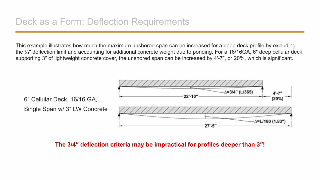
This example illustrates how much the maximum unshored span can be increased for a deep deck profile by excluding the ¾″ deflection limit and accounting for additional concrete weight due to ponding. For a 16/16GA, 6″ deep cellular deck supporting 3″ of lightweight concrete cover, the unshored span can be increased by 4′-7″, or 20%, which is significant.
The 3/4″ deflection criteria may be impractical for profiles deeper than 3″!
6″ Cellular Deck, 16/16 GA,
Single Span w/ 3″ LW Concrete
Composite Slab: Strength Requirements
A slab is considered to be composite after the concrete has been adequately cured. Composite slabs are evaluated under the load combinations required by the applicable building code or by ASCE 7, Minimum Design Loads for Buildings and Other Structures, in the absence of a building code.
Evaluated slab capacities (determined per ANSI/SDI C-2017) include: • flexural resistance in positive bending• flexural resistance in negative bending (for continuous slabs only), and• one-way and two-way (punching) shear resistance.
The flexural resistance in the positive bending, as well as the vertical shear capacity, determined per ANSI/SDI C-2017 are checked for simple supported slabs. When a slab is designed as a continuous slab, negative moment capacity of the slab shall also be checked, as will be discussed later.
The flexural resistance of composite slabs in positive bending may be governed by the shear-bond strength or by the ultimate moment capacity of the cross section assuming the perfect bond between the deck and the concrete. The shear-bond strength is the deck anchorage strength at the slab exterior support. It characterizes the degree of the composite action between the deck and the concrete.
Composite Slab: Serviceability Requirements
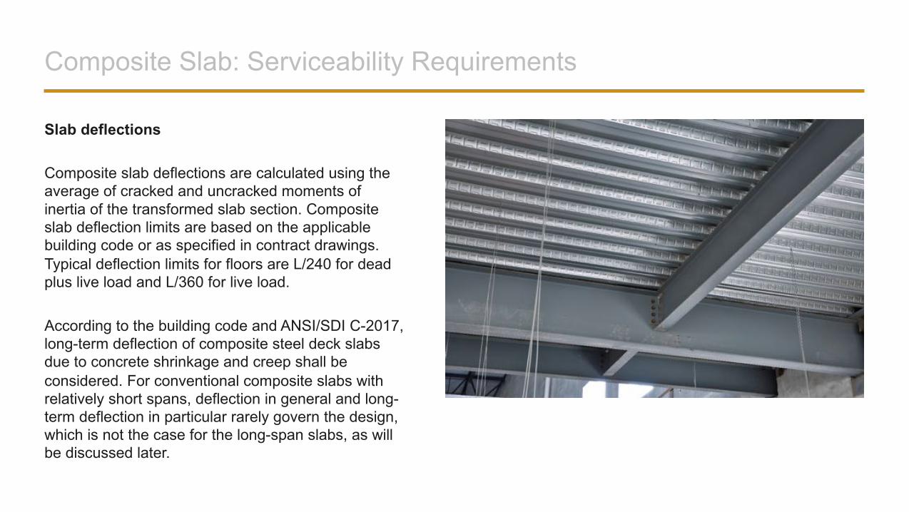
Slab deflections
Composite slab deflections are calculated using the average of cracked and uncracked moments of inertia of the transformed slab section. Composite slab deflection limits are based on the applicable building code or as specified in contract drawings. Typical deflection limits for floors are L/240 for dead plus live load and L/360 for live load.
According to the building code and ANSI/SDI C-2017, long-term deflection of composite steel deck slabs due to concrete shrinkage and creep shall be considered. For conventional composite slabs with relatively short spans, deflection in general and long-term deflection in particular rarely govern the design, which is not the case for the long-span slabs, as will be discussed later.
Composite Slab: Serviceability Requirements
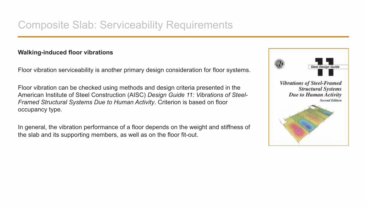
Walking-induced floor vibrations
Floor vibration serviceability is another primary design consideration for floor systems.
Floor vibration can be checked using methods and design criteria presented in the American Institute of Steel Construction (AISC) Design Guide 11: Vibrations of Steel-Framed Structural Systems Due to Human Activity. Criterion is based on floor occupancy type.
In general, the vibration performance of a floor depends on the weight and stiffness of the slab and its supporting members, as well as on the floor fit-out.
Composite Slab: Serviceability Requirements
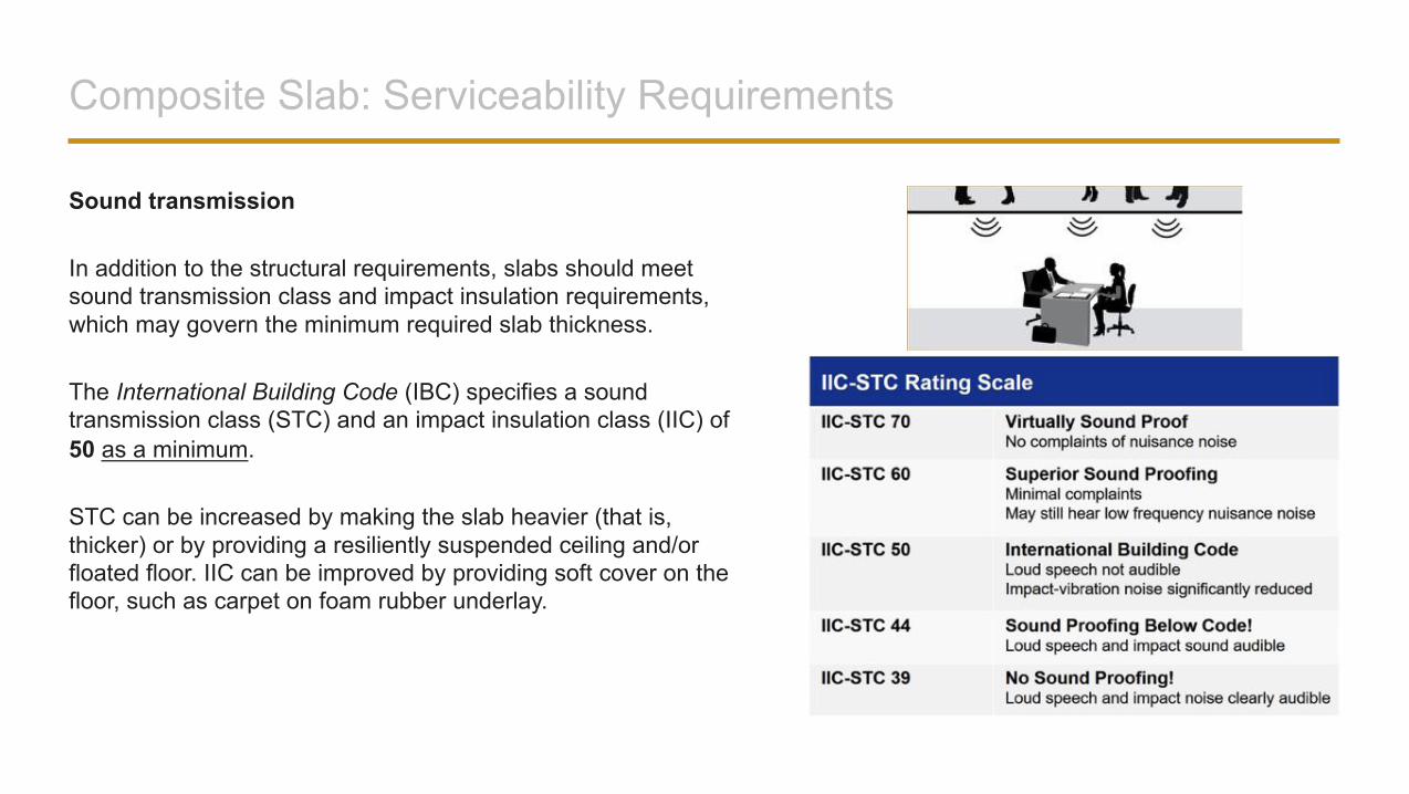
Sound transmission
In addition to the structural requirements, slabs should meet sound transmission class and impact insulation requirements, which may govern the minimum required slab thickness.
The International Building Code (IBC) specifies a sound transmission class (STC) and an impact insulation class (IIC) of 50 as a minimum.
STC can be increased by making the slab heavier (that is, thicker) or by providing a resiliently suspended ceiling and/or floated floor. IIC can be improved by providing soft cover on the floor, such as carpet on foam rubber underlay.
Composite Slab: Serviceability Requirements
Fire resistance
Last, but not the least design requirement for composite slabs is fire resistance, or the duration for which the slab can withstand a fire.
Required fire resistance is specified in the building code for different building types. Many UL fire-rated assemblies with protected and unprotected composite decks are available. Fire resistance of a composite steel deck slab can also be established by rational design per the building code, as will be discussed later.
Fill in the blanks:o The calculated deflection of deck as a form is based on the __________ determined by
the __________ and the__________ uniformly applied to all spans.
Review Question
Answer
o The calculated deflection of deck as a form is based on the concrete weight determined by the design slab thickness and the deck self-weight uniformly applied to all spans.
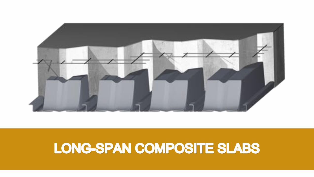
LONG-SPAN COMPOSITE SLABS
General Information
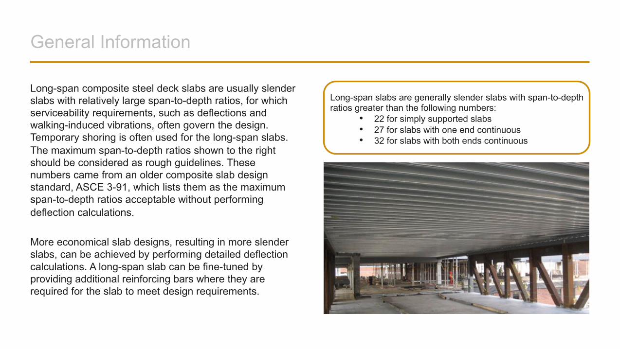
Long-span composite steel deck slabs are usually slender slabs with relatively large span-to-depth ratios, for which serviceability requirements, such as deflections and walking-induced vibrations, often govern the design. Temporary shoring is often used for the long-span slabs. The maximum span-to-depth ratios shown to the right should be considered as rough guidelines. These numbers came from an older composite slab design standard, ASCE 3-91, which lists them as the maximum span-to-depth ratios acceptable without performing deflection calculations.
More economical slab designs, resulting in more slender slabs, can be achieved by performing detailed deflection calculations. A long-span slab can be fine-tuned by providing additional reinforcing bars where they are required for the slab to meet design requirements.
Long-span slabs are generally slender slabs with span-to-depth ratios greater than the following numbers:
• 22 for simply supported slabs• 27 for slabs with one end continuous• 32 for slabs with both ends continuous
Market Solutions
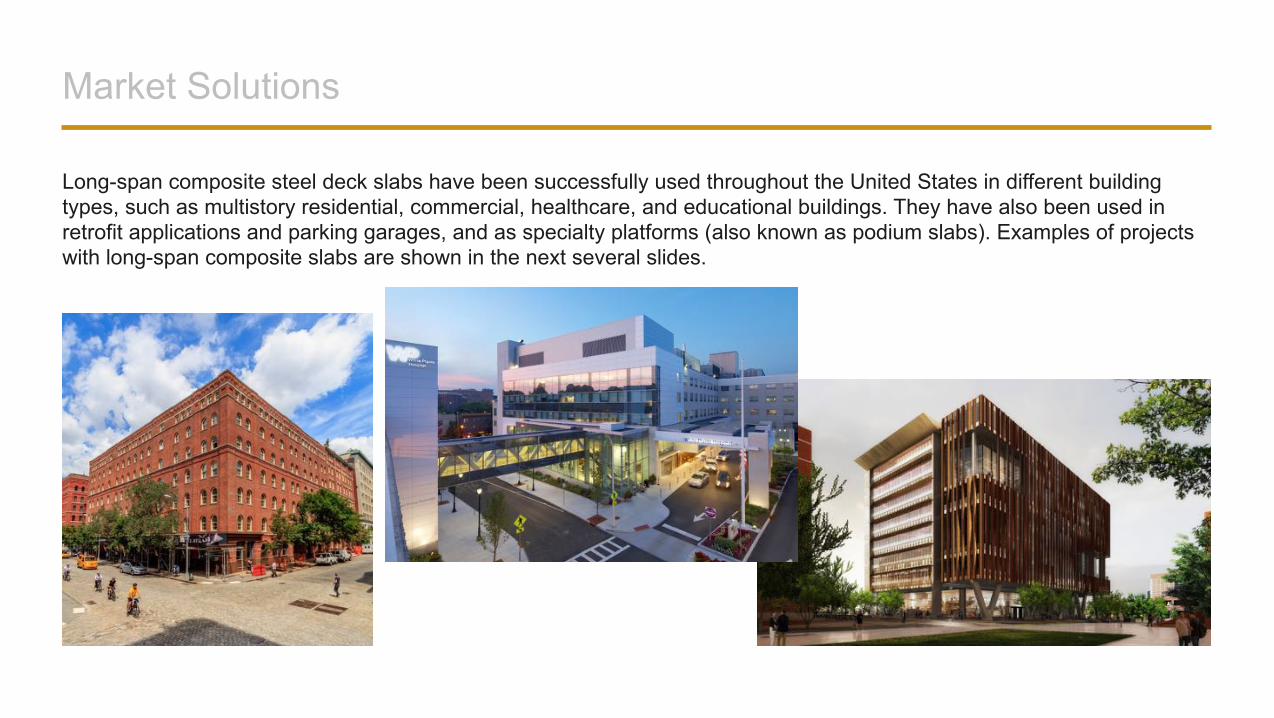
Long-span composite steel deck slabs have been successfully used throughout the United States in different building types, such as multistory residential, commercial, healthcare, and educational buildings. They have also been used in retrofit applications and parking garages, and as specialty platforms (also known as podium slabs). Examples of projects with long-span composite slabs are shown in the next several slides.
Multistory Residential Project Example
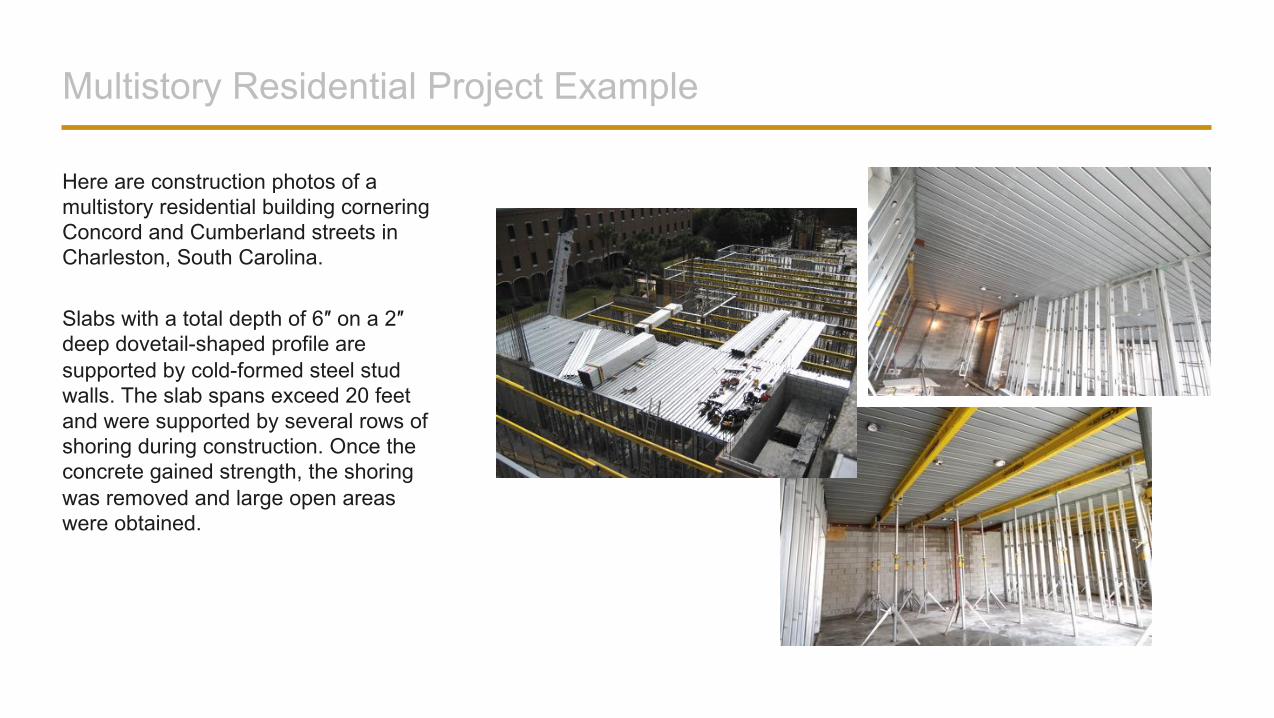
Here are construction photos of a multistory residential building cornering Concord and Cumberland streets in Charleston, South Carolina.
Slabs with a total depth of 6″ on a 2″ deep dovetail-shaped profile are supported by cold-formed steel stud walls. The slab spans exceed 20 feet and were supported by several rows of shoring during construction. Once the concrete gained strength, the shoring was removed and large open areas were obtained.
Commercial Project Example
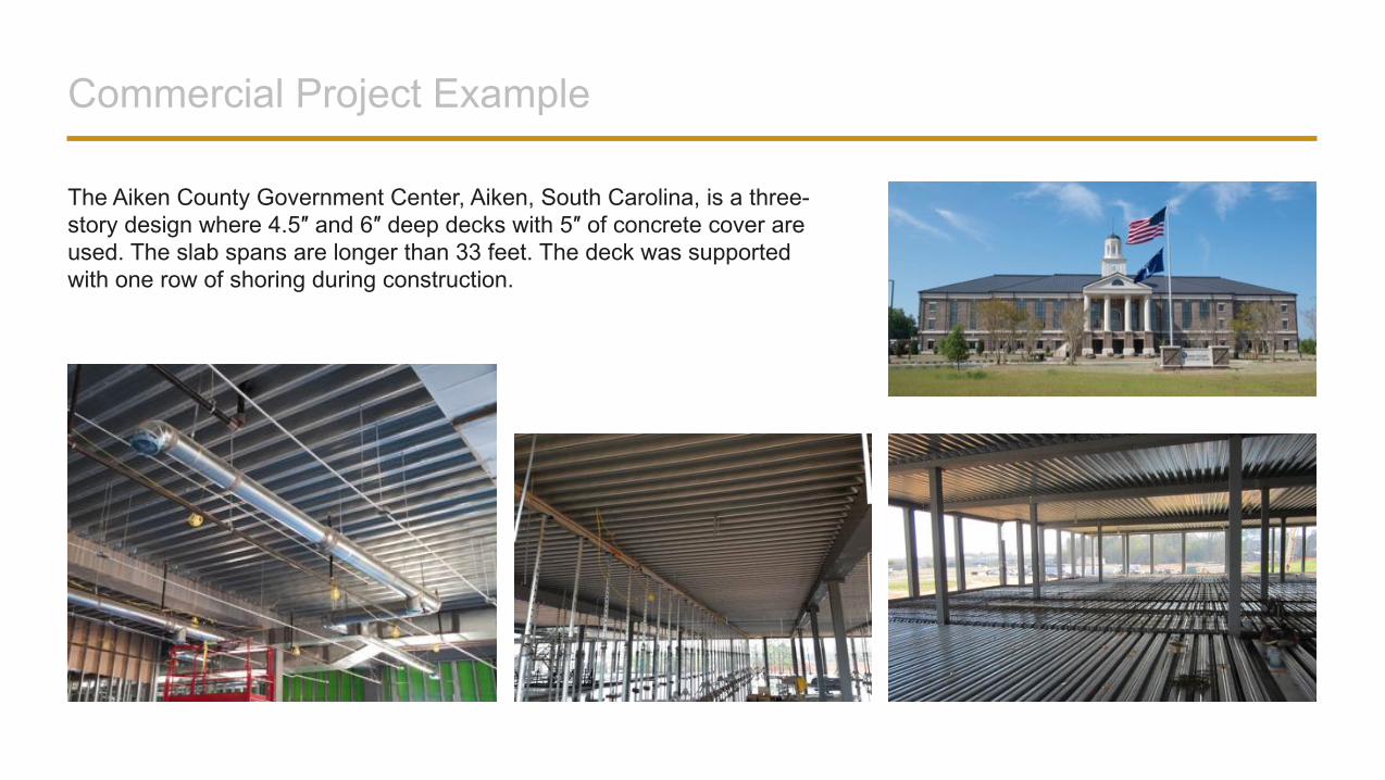
The Aiken County Government Center, Aiken, South Carolina, is a three-story design where 4.5″ and 6″ deep decks with 5″ of concrete cover are used. The slab spans are longer than 33 feet. The deck was supported with one row of shoring during construction.
Retrofit Project Example
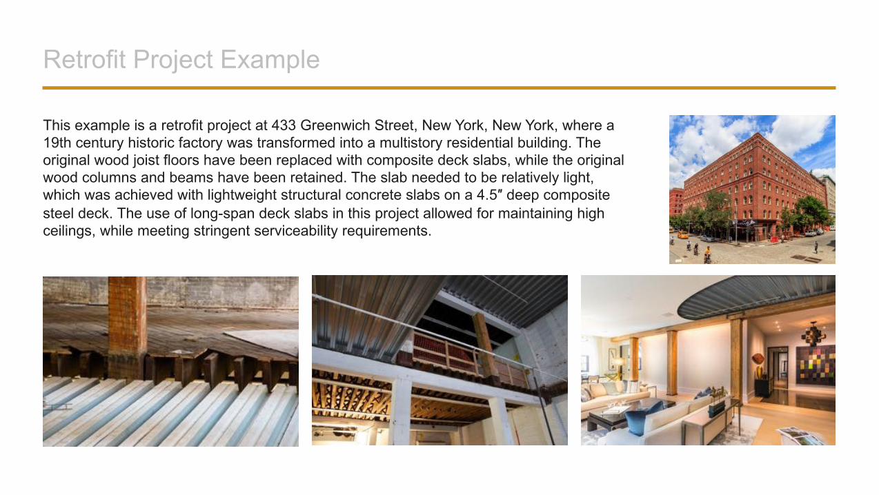
This example is a retrofit project at 433 Greenwich Street, New York, New York, where a 19th century historic factory was transformed into a multistory residential building. The original wood joist floors have been replaced with composite deck slabs, while the original wood columns and beams have been retained. The slab needed to be relatively light, which was achieved with lightweight structural concrete slabs on a 4.5″ deep composite steel deck. The use of long-span deck slabs in this project allowed for maintaining high ceilings, while meeting stringent serviceability requirements.
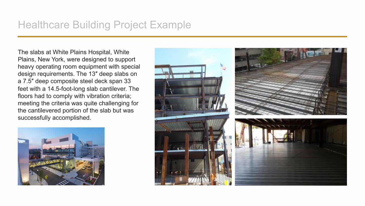
Healthcare Building Project Example
The slabs at White Plains Hospital, White Plains, New York, were designed to support heavy operating room equipment with special design requirements. The 13″ deep slabs on a 7.5″ deep composite steel deck span 33 feet with a 14.5-foot-long slab cantilever. The floors had to comply with vibration criteria; meeting the criteria was quite challenging for the cantilevered portion of the slab but was successfully accomplished.
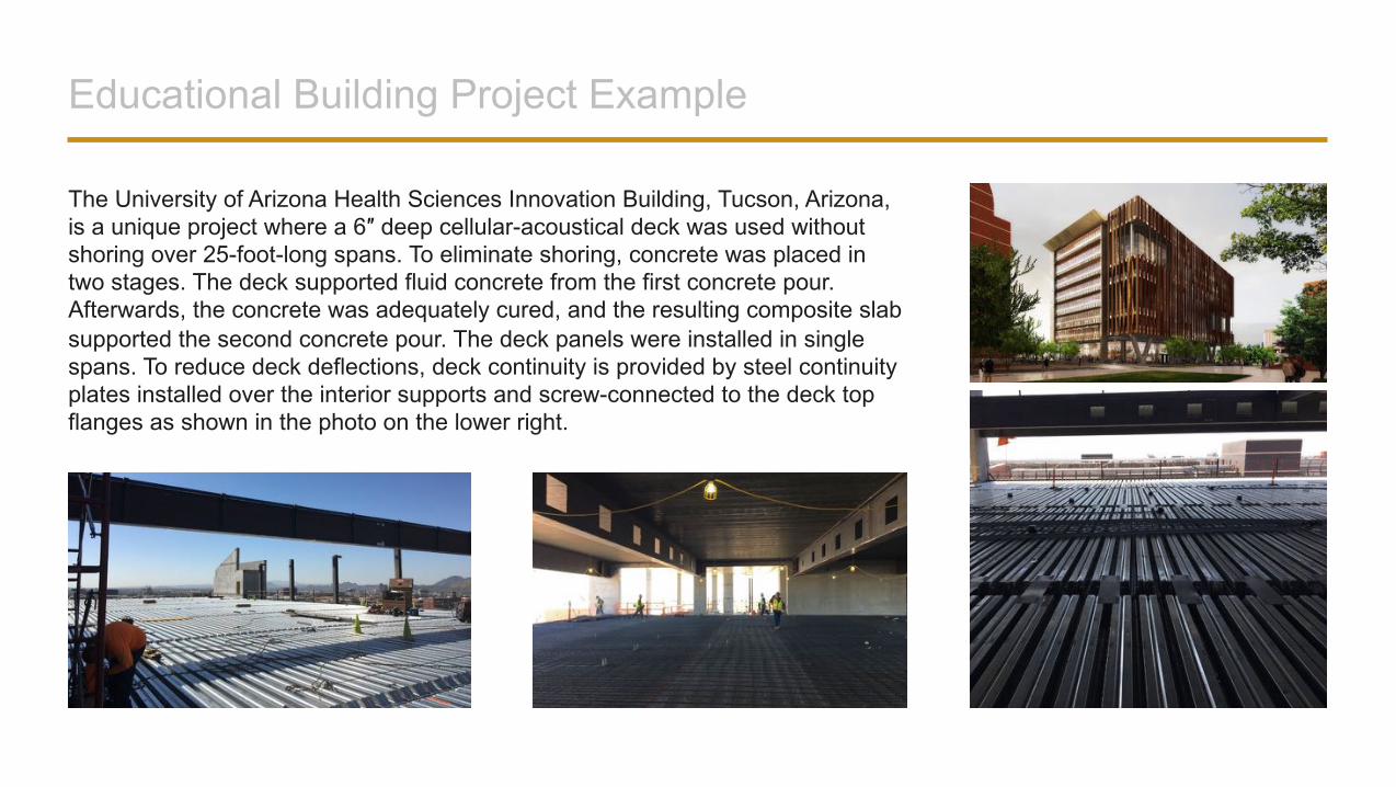
Educational Building Project Example
The University of Arizona Health Sciences Innovation Building, Tucson, Arizona, is a unique project where a 6″ deep cellular-acoustical deck was used without shoring over 25-foot-long spans. To eliminate shoring, concrete was placed in two stages. The deck supported fluid concrete from the first concrete pour. Afterwards, the concrete was adequately cured, and the resulting composite slab supported the second concrete pour. The deck panels were installed in single spans. To reduce deck deflections, deck continuity is provided by steel continuity plates installed over the interior supports and screw-connected to the deck top flanges as shown in the photo on the lower right.
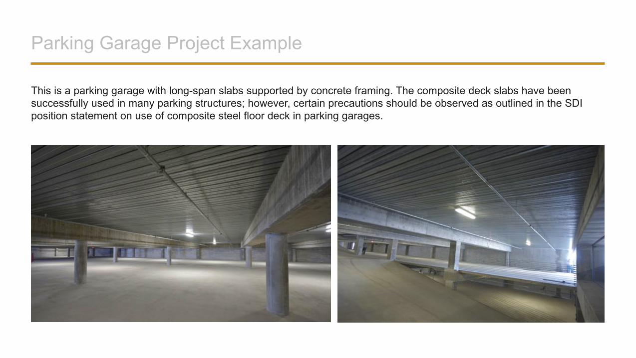
Parking Garage Project Example
This is a parking garage with long-span slabs supported by concrete framing. The composite deck slabs have been successfully used in many parking structures; however, certain precautions should be observed as outlined in the SDI position statement on use of composite steel floor deck in parking garages.
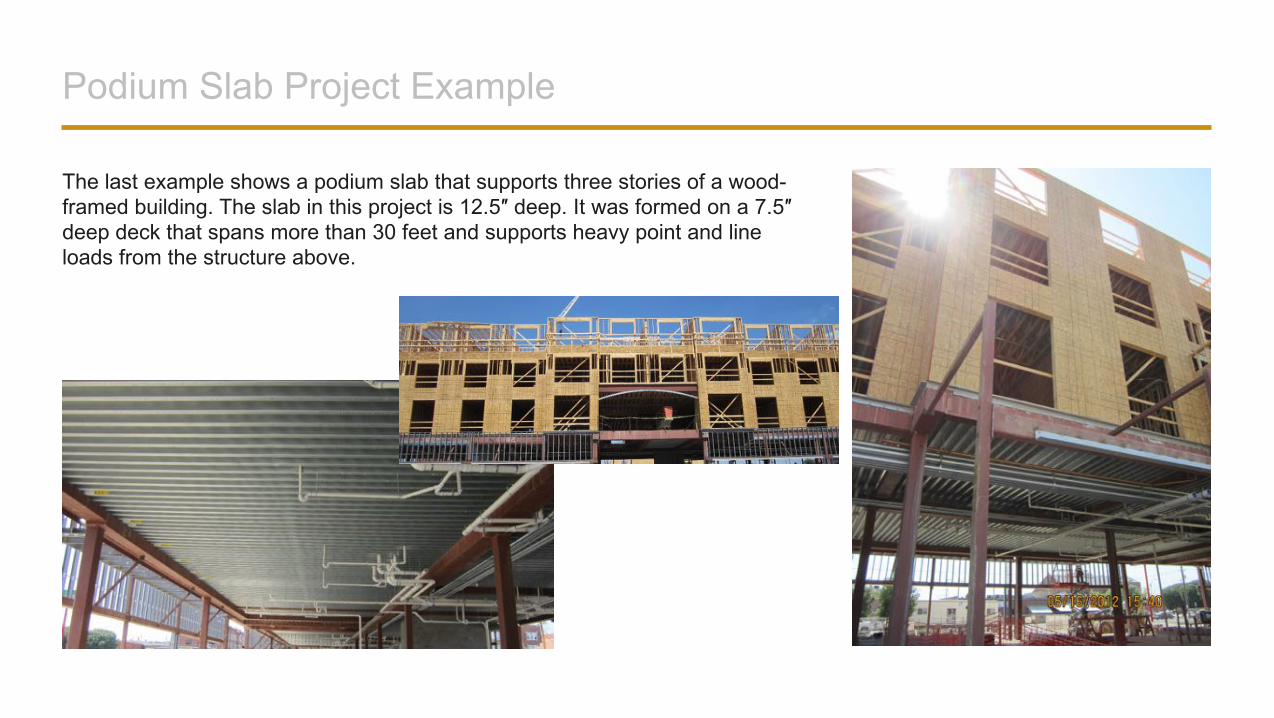
Podium Slab Project Example
The last example shows a podium slab that supports three stories of a wood-framed building. The slab in this project is 12.5″ deep. It was formed on a 7.5″ deep deck that spans more than 30 feet and supports heavy point and line loads from the structure above.
SPECIAL DESIGN CONSIDERATIONS
Additional Reinforcing Bars
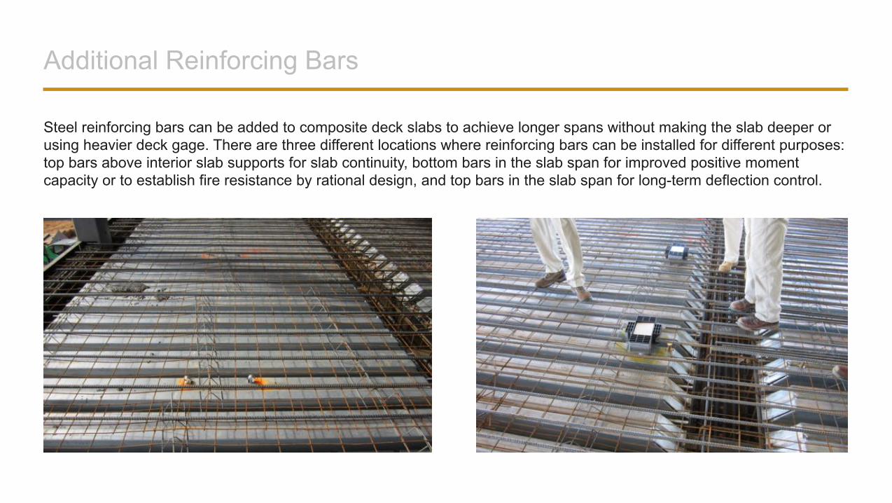
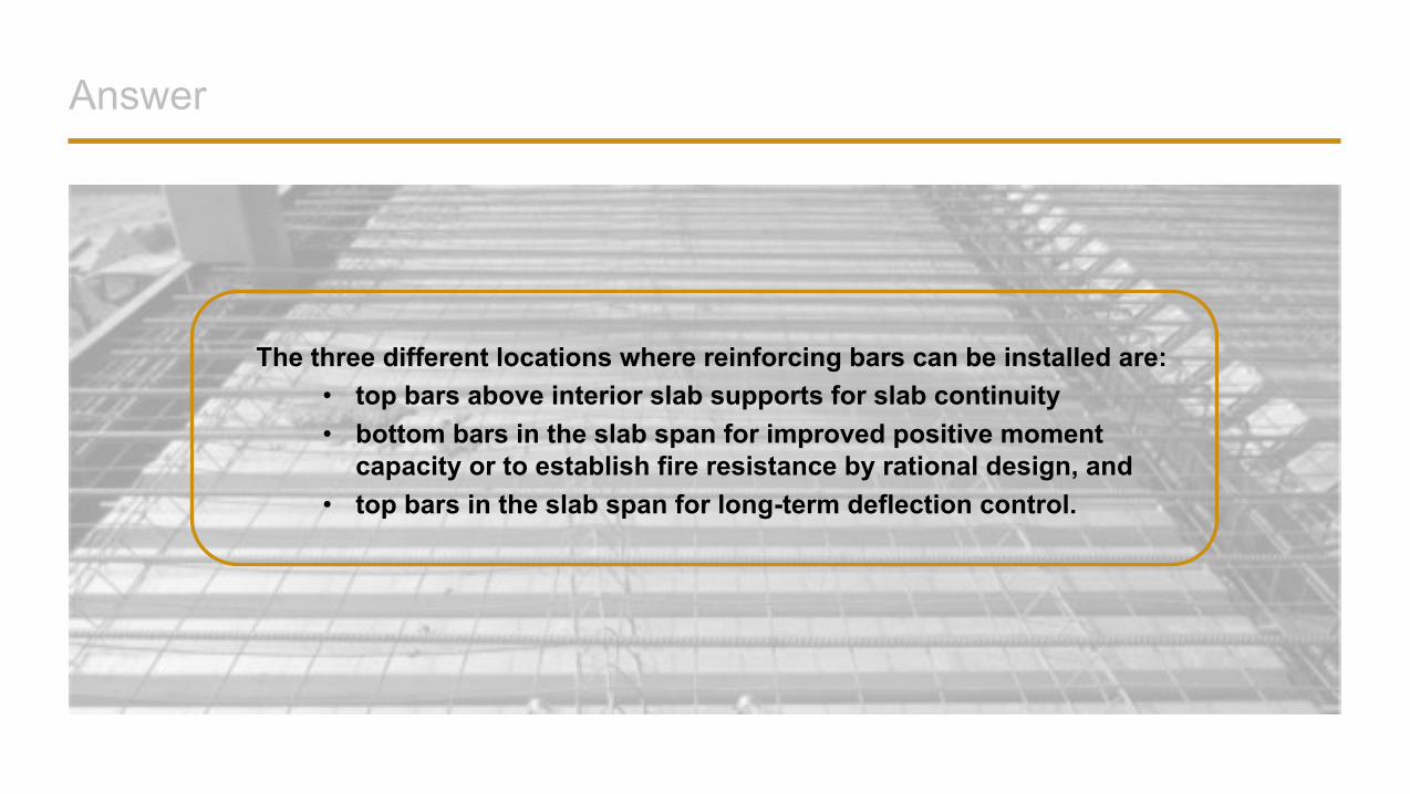
Steel reinforcing bars can be added to composite deck slabs to achieve longer spans without making the slab deeper or using heavier deck gage. There are three different locations where reinforcing bars can be installed for different purposes: top bars above interior slab supports for slab continuity, bottom bars in the slab span for improved positive moment capacity or to establish fire resistance by rational design, and top bars in the slab span for long-term deflection control.
Slab Continuity
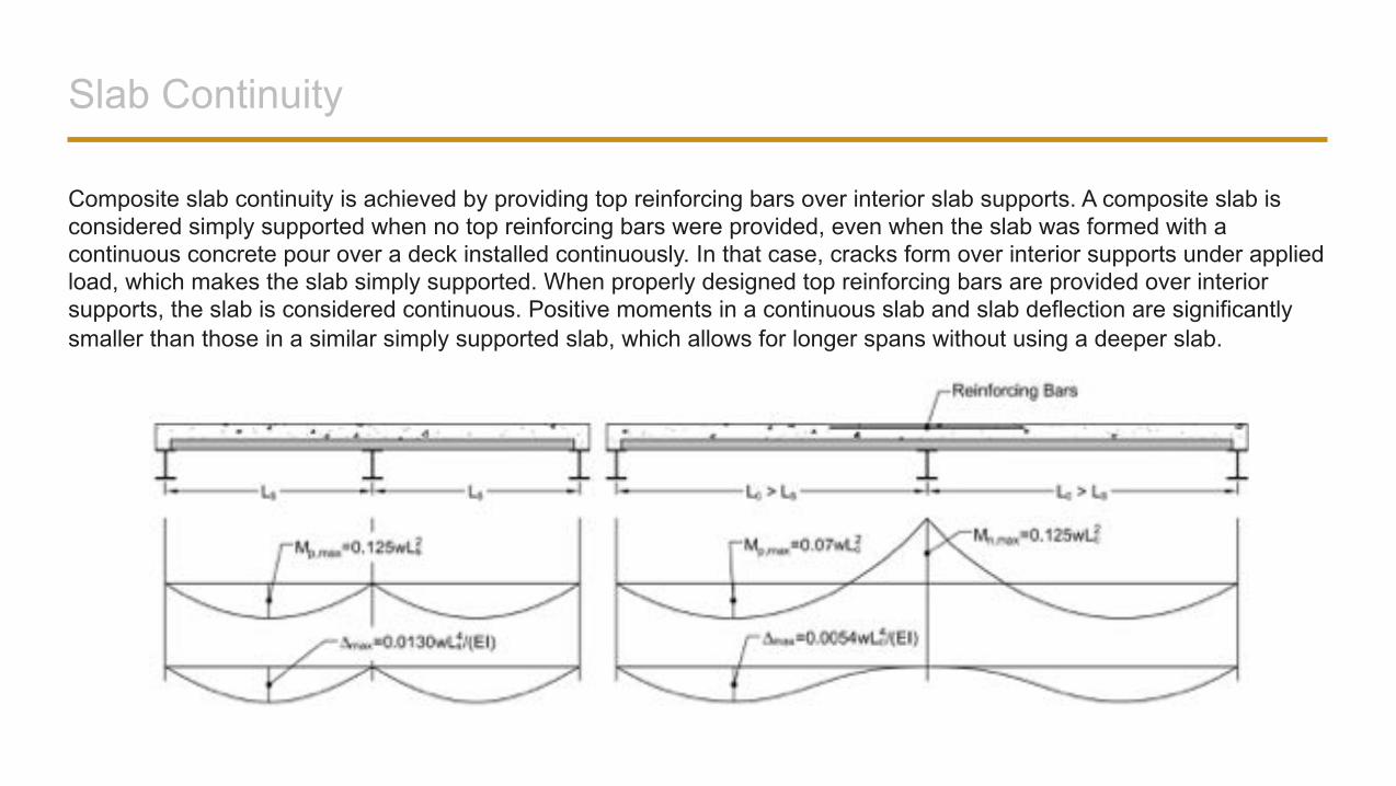
Composite slab continuity is achieved by providing top reinforcing bars over interior slab supports. A composite slab is considered simply supported when no top reinforcing bars were provided, even when the slab was formed with a continuous concrete pour over a deck installed continuously. In that case, cracks form over interior supports under applied load, which makes the slab simply supported. When properly designed top reinforcing bars are provided over interior supports, the slab is considered continuous. Positive moments in a continuous slab and slab deflection are significantly smaller than those in a similar simply supported slab, which allows for longer spans without using a deeper slab.
Design of Continuous Slabs
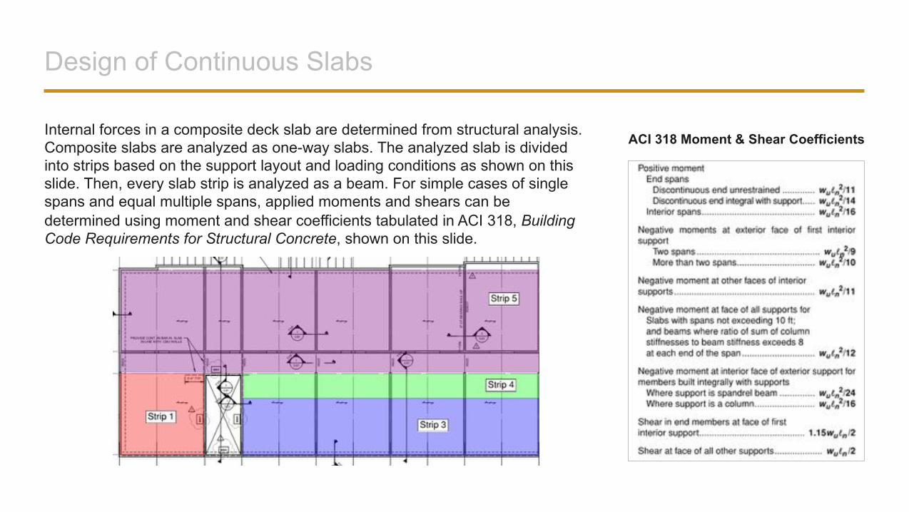
Internal forces in a composite deck slab are determined from structural analysis. Composite slabs are analyzed as one-way slabs. The analyzed slab is divided into strips based on the support layout and loading conditions as shown on this slide. Then, every slab strip is analyzed as a beam. For simple cases of single spans and equal multiple spans, applied moments and shears can be determined using moment and shear coefficients tabulated in ACI 318, Building Code Requirements for Structural Concrete, shown on this slide.
ACI 318 Moment & Shear Coefficients
Design of Continuous Slabs
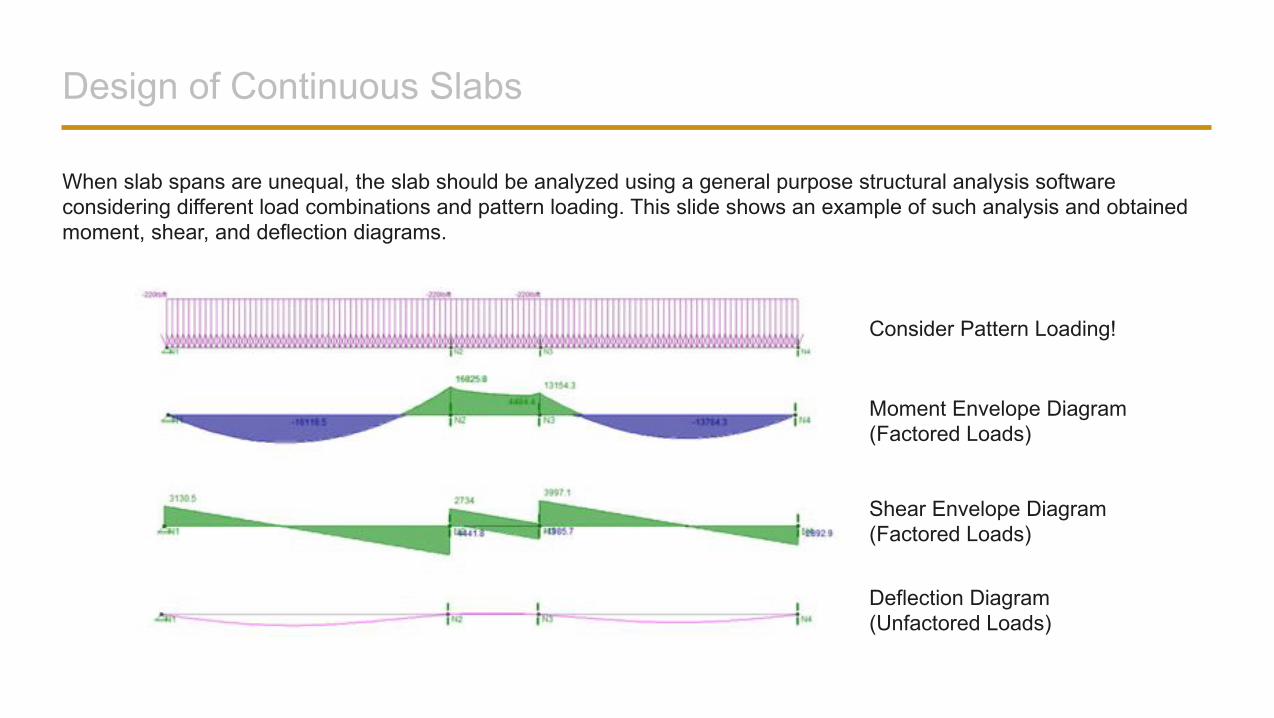
When slab spans are unequal, the slab should be analyzed using a general purpose structural analysis software considering different load combinations and pattern loading. This slide shows an example of such analysis and obtained moment, shear, and deflection diagrams.
Moment Envelope Diagram(Factored Loads)
Shear Envelope Diagram(Factored Loads)
Deflection Diagram(Unfactored Loads)
Consider Pattern Loading!
Design of Continuous Slabs
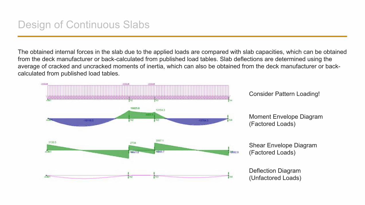
The obtained internal forces in the slab due to the applied loads are compared with slab capacities, which can be obtained from the deck manufacturer or back-calculated from published load tables. Slab deflections are determined using the average of cracked and uncracked moments of inertia, which can also be obtained from the deck manufacturer or back-calculated from published load tables.
Moment Envelope Diagram(Factored Loads)
Shear Envelope Diagram(Factored Loads)
Deflection Diagram(Unfactored Loads)
Consider Pattern Loading!
Design of Continuous Slabs
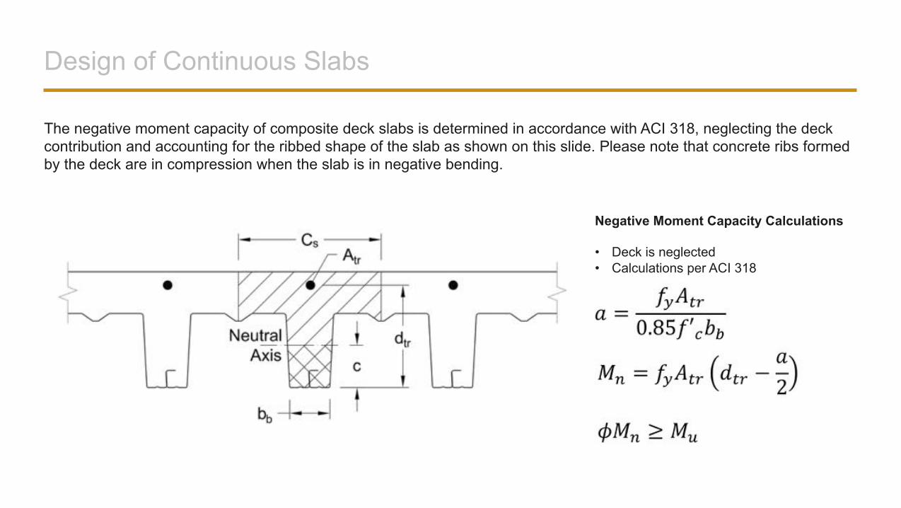
The negative moment capacity of composite deck slabs is determined in accordance with ACI 318, neglecting the deck contribution and accounting for the ribbed shape of the slab as shown on this slide. Please note that concrete ribs formed by the deck are in compression when the slab is in negative bending.
Negative Moment Capacity Calculations
• Deck is neglected• Calculations per ACI 318
Bottom Reinforcing Bars in Slab Span
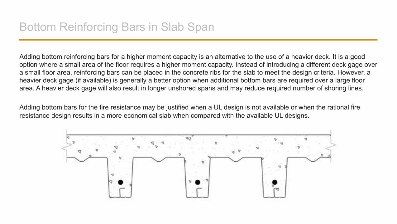
Adding bottom reinforcing bars for a higher moment capacity is an alternative to the use of a heavier deck. It is a good option where a small area of the floor requires a higher moment capacity. Instead of introducing a different deck gage over a small floor area, reinforcing bars can be placed in the concrete ribs for the slab to meet the design criteria. However, a heavier deck gage (if available) is generally a better option when additional bottom bars are required over a large floor area. A heavier deck gage will also result in longer unshored spans and may reduce required number of shoring lines.
Adding bottom bars for the fire resistance may be justified when a UL design is not available or when the rational fire resistance design results in a more economical slab when compared with the available UL designs.
Bottom Reinforcing Bars in Slab Span
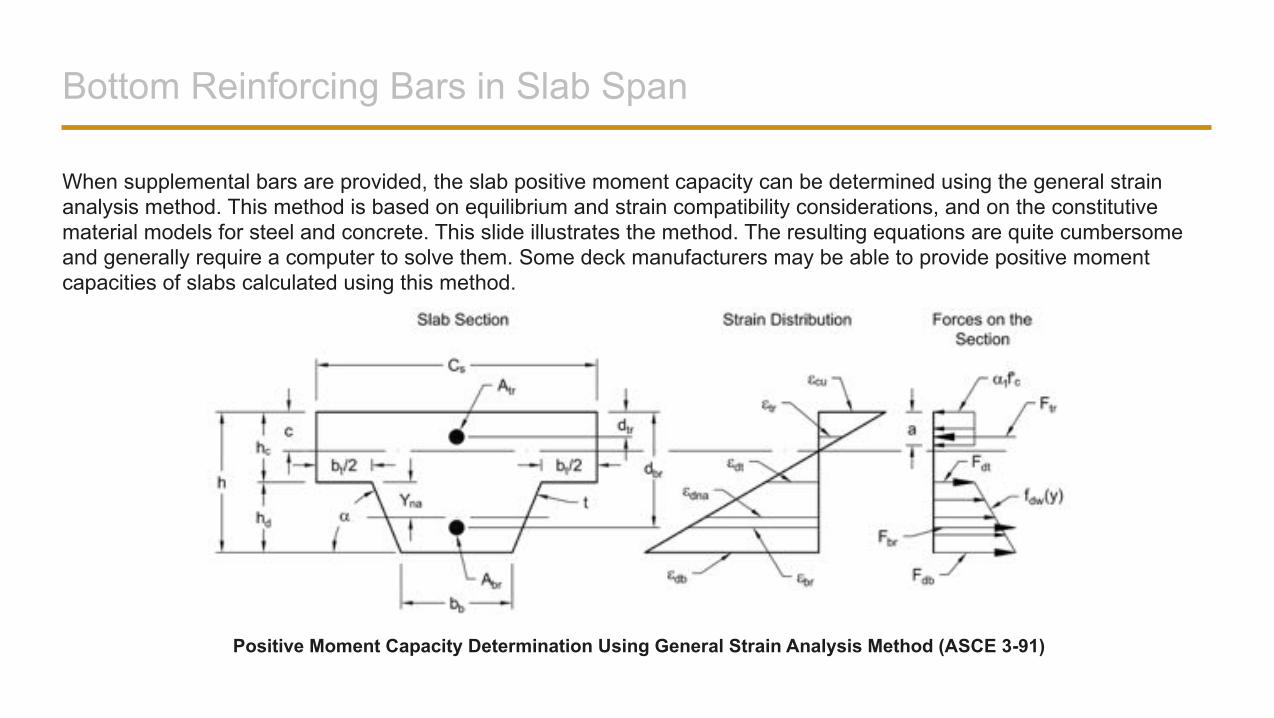
When supplemental bars are provided, the slab positive moment capacity can be determined using the general strain analysis method. This method is based on equilibrium and strain compatibility considerations, and on the constitutive material models for steel and concrete. This slide illustrates the method. The resulting equations are quite cumbersome and generally require a computer to solve them. Some deck manufacturers may be able to provide positive moment capacities of slabs calculated using this method.
Positive Moment Capacity Determination Using General Strain Analysis Method (ASCE 3-91)
Composite Slab Fire Resistance by Calculations
The IBC permits establishing fire resistance of structural concrete slabs by calculations using Section 722, which references ACI 216.1, Code Requirements for Determining Fire Resistance of Concrete and Masonry Construction Assemblies. When a composite deck slab is designed for a fire event, the deck is ignored and the slab is analyzed as a reinforced concrete slab. Because the deck is ignored, bottom reinforcing bars are required for the slab to support design loads.
To meet thermal insulation requirements, the minimum required equivalent thickness of the slab specified by the building code has to be provided. Next, rebar and concrete temperatures are determined based on the slab geometry, concrete density, and the fire exposure duration. The temperatures are determined using multiple charts published in ACI 216.1 for different design conditions.
Afterwards, rebar and concrete strength reductions are obtained based on the temperatures determined in the previous step. Finally, the slab capacity is calculated using the reduced rebar and concrete strengths and compared with the applied moment.
Top Reinforcing Bars: Long-Term Deflection Control
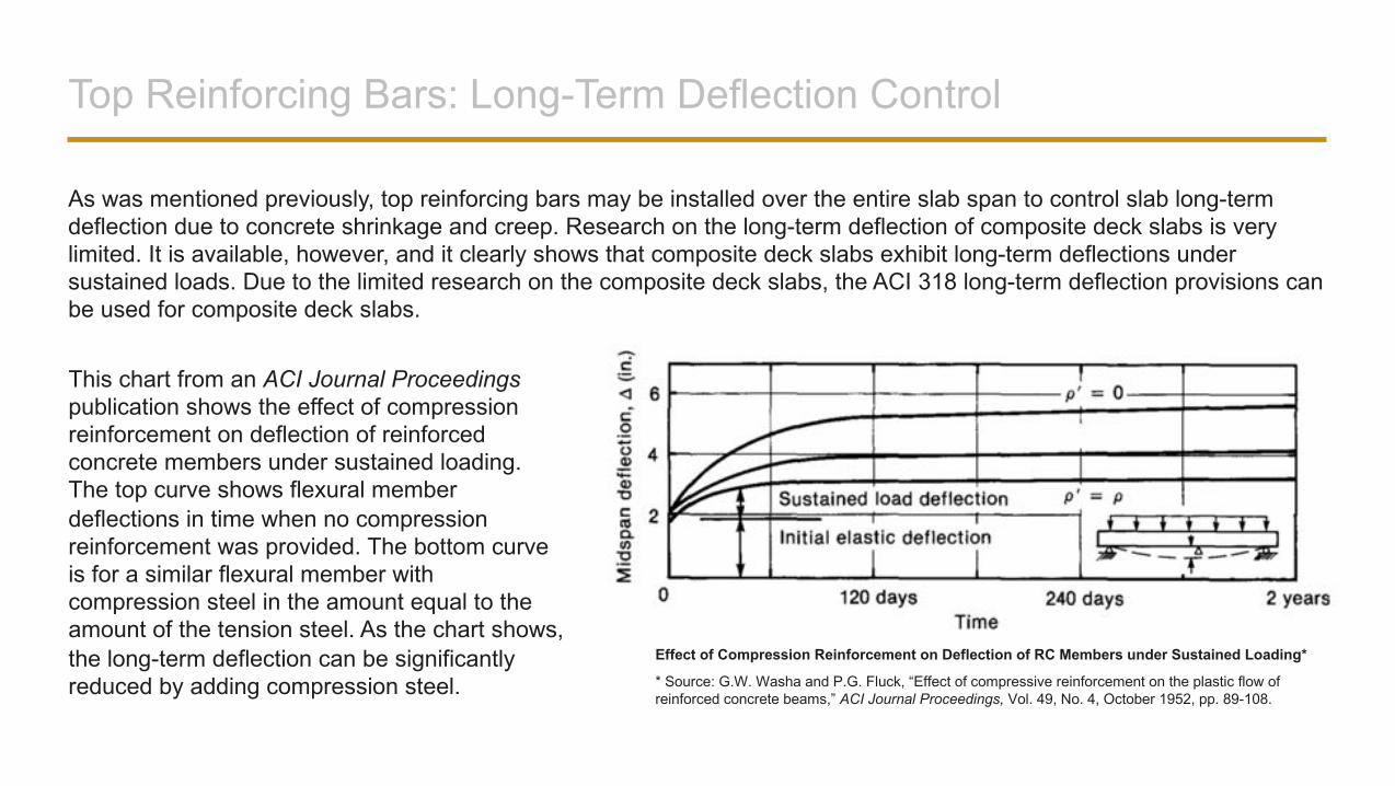
As was mentioned previously, top reinforcing bars may be installed over the entire slab span to control slab long-term deflection due to concrete shrinkage and creep. Research on the long-term deflection of composite deck slabs is very limited. It is available, however, and it clearly shows that composite deck slabs exhibit long-term deflections under sustained loads. Due to the limited research on the composite deck slabs, the ACI 318 long-term deflection provisions can be used for composite deck slabs.
Effect of Compression Reinforcement on Deflection of RC Members under Sustained Loading*
This chart from an ACI Journal Proceedings publication shows the effect of compression reinforcement on deflection of reinforced concrete members under sustained loading. The top curve shows flexural member deflections in time when no compression reinforcement was provided. The bottom curve is for a similar flexural member with compression steel in the amount equal to the amount of the tension steel. As the chart shows, the long-term deflection can be significantly reduced by adding compression steel. * Source: G.W. Washa and P.G. Fluck, “Effect of compressive reinforcement on the plastic flow of
reinforced concrete beams,” ACI Journal Proceedings, Vol. 49, No. 4, October 1952, pp. 89-108.
Top Reinforcing Bars: Long-Term Deflection Control
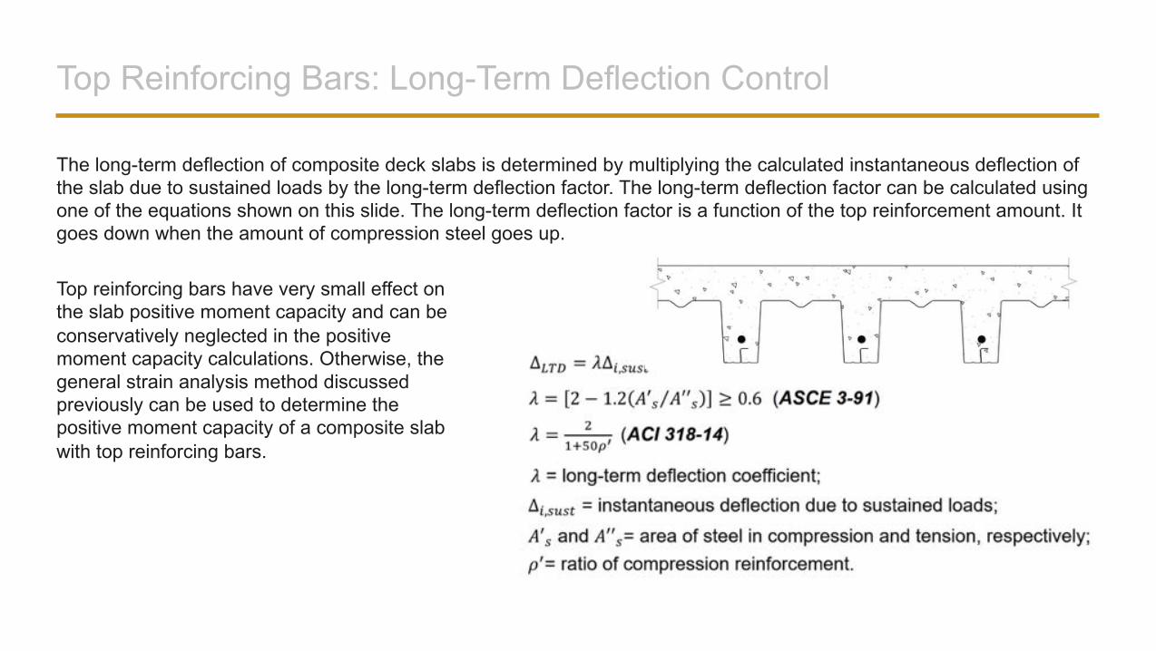
The long-term deflection of composite deck slabs is determined by multiplying the calculated instantaneous deflection of the slab due to sustained loads by the long-term deflection factor. The long-term deflection factor can be calculated using one of the equations shown on this slide. The long-term deflection factor is a function of the top reinforcement amount. It goes down when the amount of compression steel goes up.
Top reinforcing bars have very small effect on the slab positive moment capacity and can be conservatively neglected in the positive moment capacity calculations. Otherwise, thegeneral strain analysis method discussed previously can be used to determine the positive moment capacity of a composite slabwith top reinforcing bars.
Shear Studs Welded Through Deck
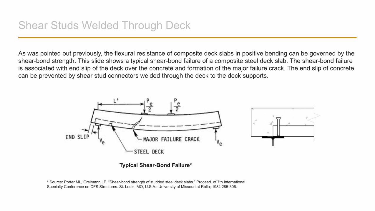
As was pointed out previously, the flexural resistance of composite deck slabs in positive bending can be governed by the shear-bond strength. This slide shows a typical shear-bond failure of a composite steel deck slab. The shear-bond failure is associated with end slip of the deck over the concrete and formation of the major failure crack. The end slip of concrete can be prevented by shear stud connectors welded through the deck to the deck supports.
Typical Shear-Bond Failure*
* Source: Porter ML, Greimann LF. “Shear-bond strength of studded steel deck slabs.” Proceed. of 7th International Specialty Conference on CFS Structures. St. Louis, MO, U.S.A.: University of Missouri at Rolla; 1984:285-306.
Shear Studs Welded Through Deck
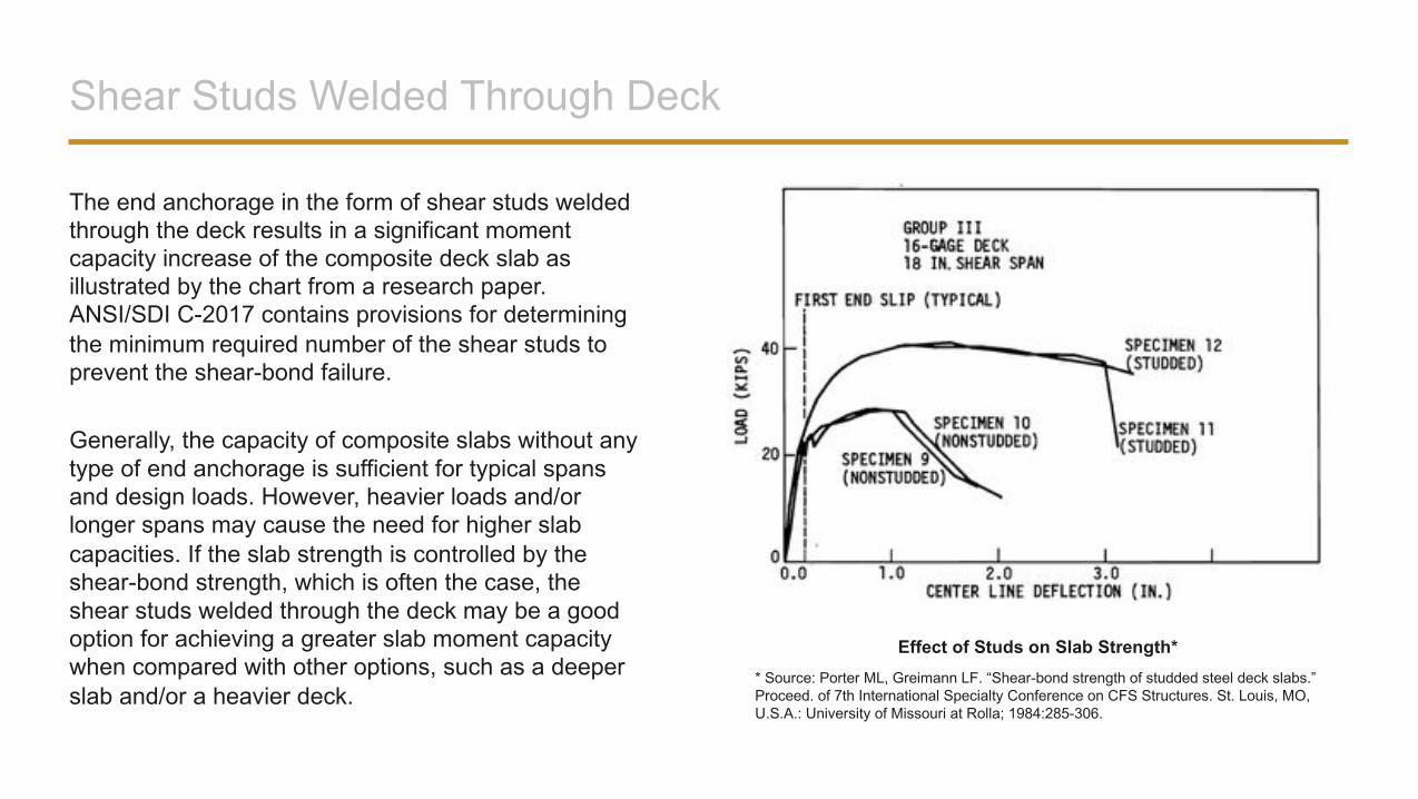
The end anchorage in the form of shear studs welded through the deck results in a significant moment capacity increase of the composite deck slab as illustrated by the chart from a research paper. ANSI/SDI C-2017 contains provisions for determining the minimum required number of the shear studs to prevent the shear-bond failure.
Generally, the capacity of composite slabs without any type of end anchorage is sufficient for typical spans and design loads. However, heavier loads and/or longer spans may cause the need for higher slab capacities. If the slab strength is controlled by the shear-bond strength, which is often the case, the shear studs welded through the deck may be a good option for achieving a greater slab moment capacity when compared with other options, such as a deeper slab and/or a heavier deck.
* Source: Porter ML, Greimann LF. “Shear-bond strength of studded steel deck slabs.” Proceed. of 7th International Specialty Conference on CFS Structures. St. Louis, MO, U.S.A.: University of Missouri at Rolla; 1984:285-306.
Effect of Studs on Slab Strength*
Concentrated Loads
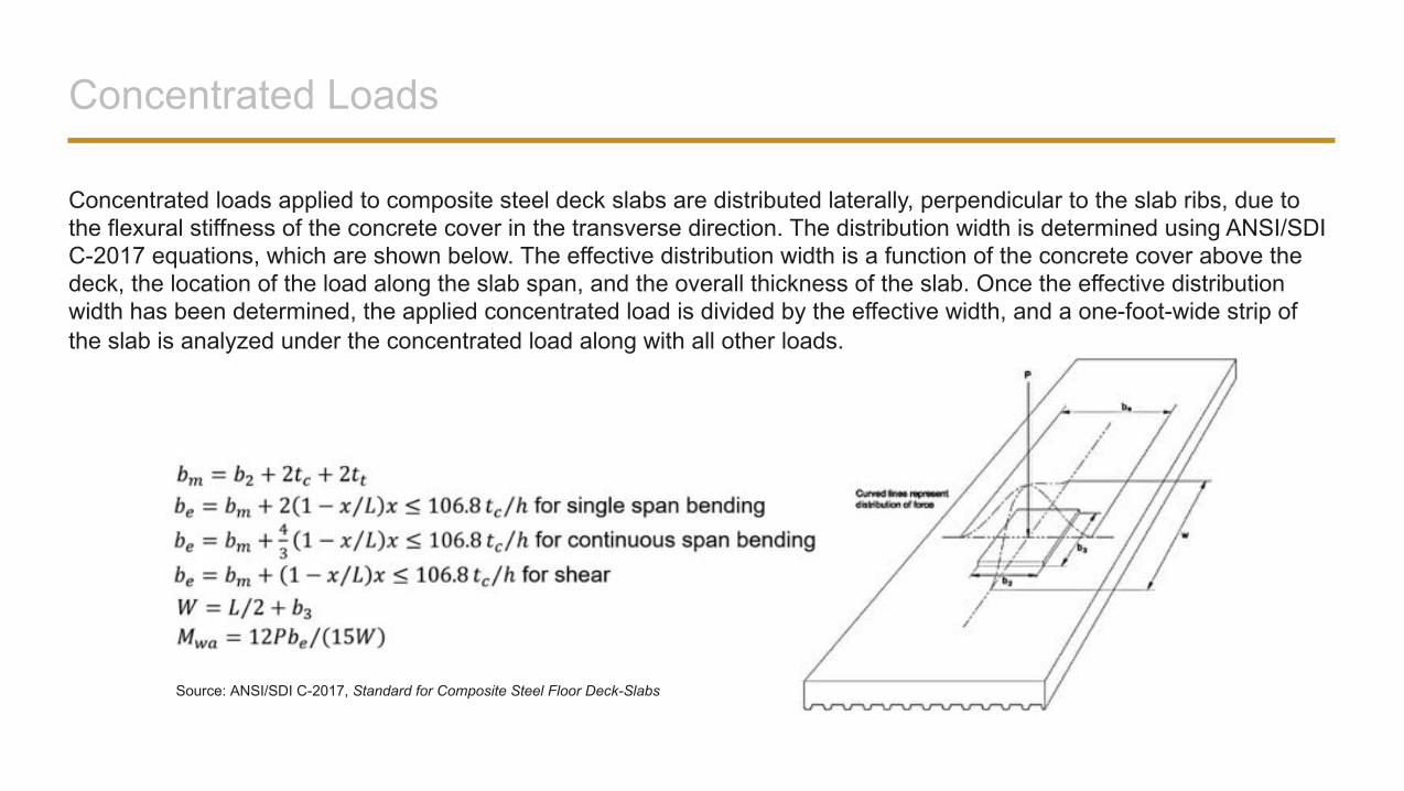
Concentrated loads applied to composite steel deck slabs are distributed laterally, perpendicular to the slab ribs, due to the flexural stiffness of the concrete cover in the transverse direction. The distribution width is determined using ANSI/SDIC-2017 equations, which are shown below. The effective distribution width is a function of the concrete cover above the deck, the location of the load along the slab span, and the overall thickness of the slab. Once the effective distribution width has been determined, the applied concentrated load is divided by the effective width, and a one-foot-wide strip of the slab is analyzed under the concentrated load along with all other loads.
Source: ANSI/SDI C-2017, Standard for Composite Steel Floor Deck-Slabs
Concentrated Loads
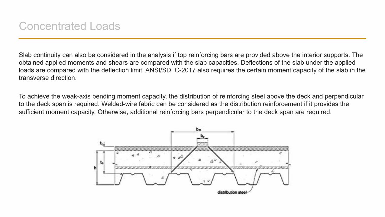
Slab continuity can also be considered in the analysis if top reinforcing bars are provided above the interior supports. The obtained applied moments and shears are compared with the slab capacities. Deflections of the slab under the applied loads are compared with the deflection limit. ANSI/SDI C-2017 also requires the certain moment capacity of the slab in the transverse direction.
To achieve the weak-axis bending moment capacity, the distribution of reinforcing steel above the deck and perpendicular to the deck span is required. Welded-wire fabric can be considered as the distribution reinforcement if it provides the sufficient moment capacity. Otherwise, additional reinforcing bars perpendicular to the deck span are required.
Slab Openings
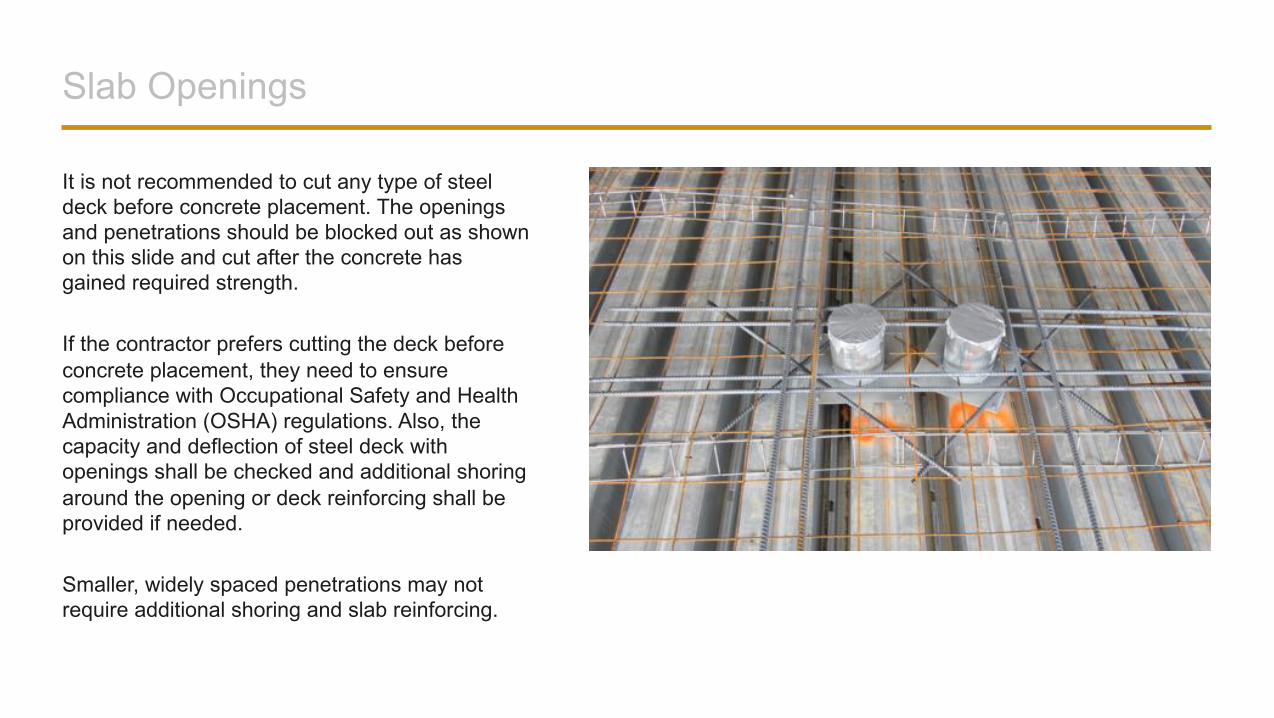
It is not recommended to cut any type of steel deck before concrete placement. The openings and penetrations should be blocked out as shown on this slide and cut after the concrete has gained required strength.
If the contractor prefers cutting the deck before concrete placement, they need to ensure compliance with Occupational Safety and Health Administration (OSHA) regulations. Also, the capacity and deflection of steel deck with openings shall be checked and additional shoring around the opening or deck reinforcing shall be provided if needed.
Smaller, widely spaced penetrations may not require additional shoring and slab reinforcing.
Slab Openings
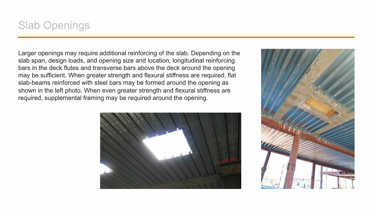
Larger openings may require additional reinforcing of the slab. Depending on the slab span, design loads, and opening size and location, longitudinal reinforcing bars in the deck flutes and transverse bars above the deck around the opening may be sufficient. When greater strength and flexural stiffness are required, flat slab-beams reinforced with steel bars may be formed around the opening as shown in the left photo. When even greater strength and flexural stiffness are required, supplemental framing may be required around the opening.
Slab Openings
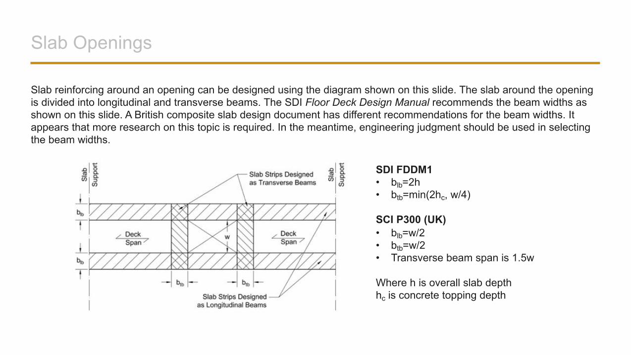
Slab reinforcing around an opening can be designed using the diagram shown on this slide. The slab around the opening is divided into longitudinal and transverse beams. The SDI Floor Deck Design Manual recommends the beam widths as shown on this slide. A British composite slab design document has different recommendations for the beam widths. It appears that more research on this topic is required. In the meantime, engineering judgment should be used in selecting the beam widths.
SDI FDDM1• blb=2h• btb=min(2hc, w/4)
SCI P300 (UK)• blb=w/2• btb=w/2• Transverse beam span is 1.5w
Where h is overall slab depthhc is concrete topping depth
Slab Openings
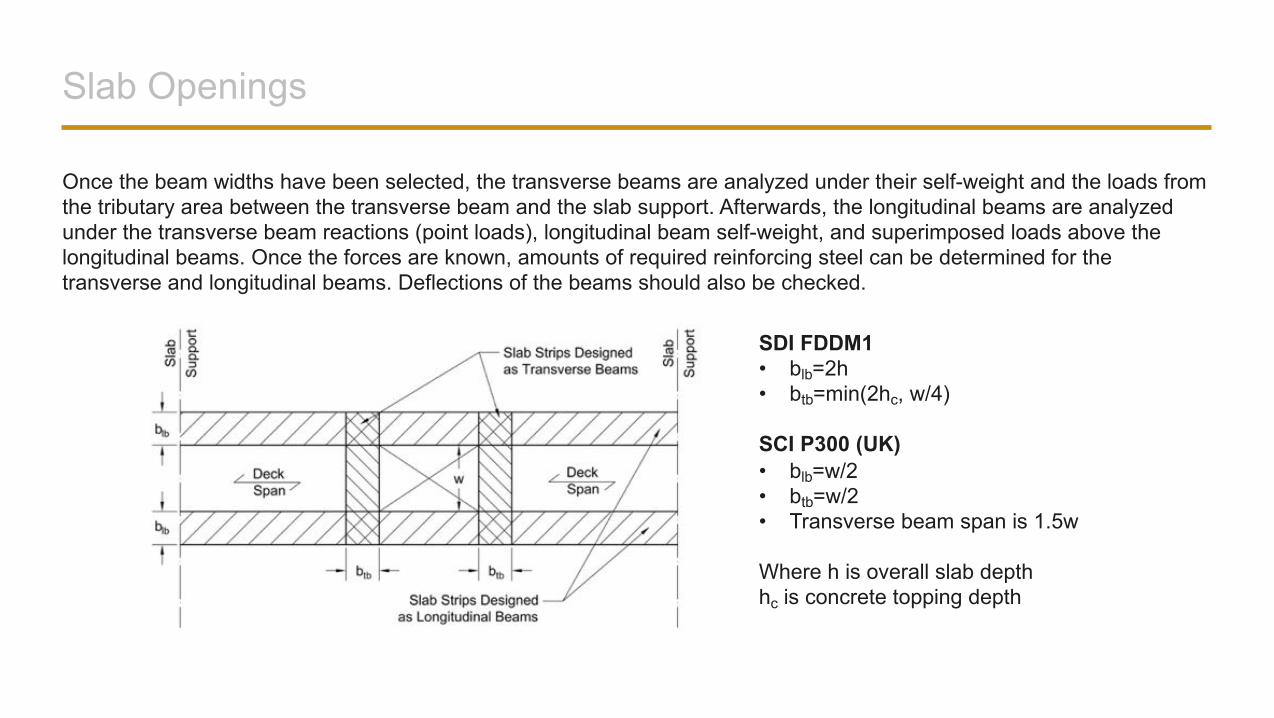
Once the beam widths have been selected, the transverse beams are analyzed under their self-weight and the loads from the tributary area between the transverse beam and the slab support. Afterwards, the longitudinal beams are analyzed under the transverse beam reactions (point loads), longitudinal beam self-weight, and superimposed loads above the longitudinal beams. Once the forces are known, amounts of required reinforcing steel can be determined for the transverse and longitudinal beams. Deflections of the beams should also be checked.
SDI FDDM1• blb=2h• btb=min(2hc, w/4)
SCI P300 (UK)• blb=w/2• btb=w/2• Transverse beam span is 1.5w
Where h is overall slab depthhc is concrete topping depth
Slab Openings
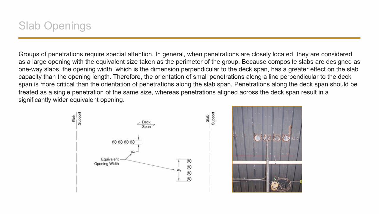
Groups of penetrations require special attention. In general, when penetrations are closely located, they are considered as a large opening with the equivalent size taken as the perimeter of the group. Because composite slabs are designed as one-way slabs, the opening width, which is the dimension perpendicular to the deck span, has a greater effect on the slab capacity than the opening length. Therefore, the orientation of small penetrations along a line perpendicular to the deck span is more critical than the orientation of penetrations along the slab span. Penetrations along the deck span should be treated as a single penetration of the same size, whereas penetrations aligned across the deck span result in a significantly wider equivalent opening.
Walking-Induced Floor Vibrations
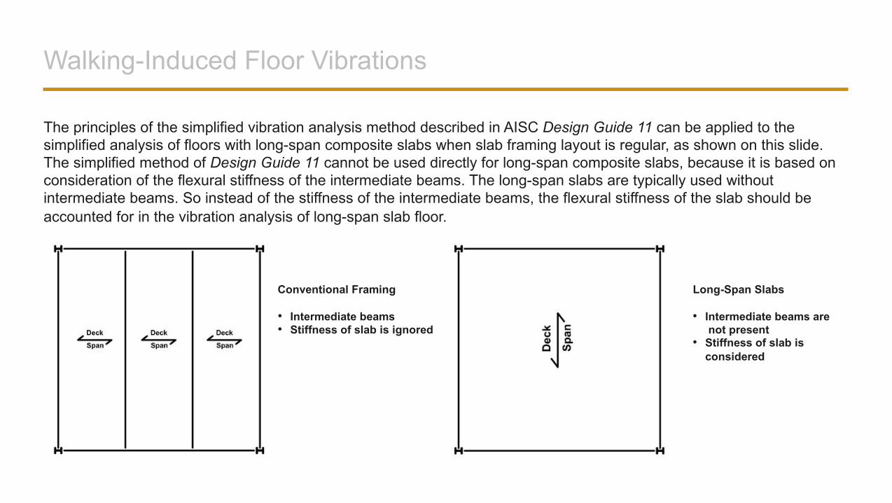
The principles of the simplified vibration analysis method described in AISC Design Guide 11 can be applied to the simplified analysis of floors with long-span composite slabs when slab framing layout is regular, as shown on this slide. The simplified method of Design Guide 11 cannot be used directly for long-span composite slabs, because it is based on consideration of the flexural stiffness of the intermediate beams. The long-span slabs are typically used without intermediate beams. So instead of the stiffness of the intermediate beams, the flexural stiffness of the slab should be accounted for in the vibration analysis of long-span slab floor.
Conventional Framing Long-Span Slabs
• Intermediate beams• Stiffness of slab is ignored
• Intermediate beams arenot present
• Stiffness of slab is considered
Walking-Induced Floor Vibrations
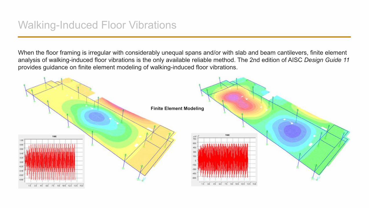
When the floor framing is irregular with considerably unequal spans and/or with slab and beam cantilevers, finite element analysis of walking-induced floor vibrations is the only available reliable method. The 2nd edition of AISC Design Guide 11 provides guidance on finite element modeling of walking-induced floor vibrations.
Finite Element Modeling
Review Question
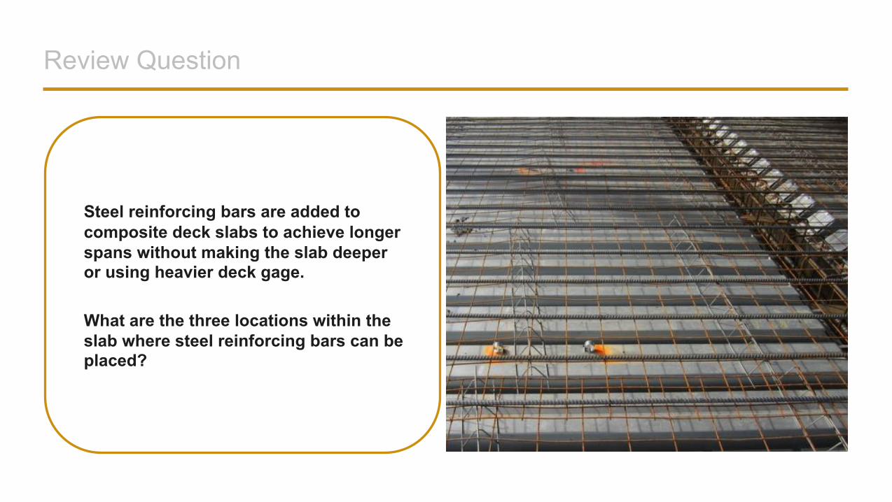
Steel reinforcing bars are added to composite deck slabs to achieve longer spans without making the slab deeper or using heavier deck gage.
What are the three locations within the slab where steel reinforcing bars can be placed?
Answer
The three different locations where reinforcing bars can be installed are:• top bars above interior slab supports for slab continuity• bottom bars in the slab span for improved positive moment
capacity or to establish fire resistance by rational design, and• top bars in the slab span for long-term deflection control.
FREQUENTLY ASKED QUESTIONS
Who Is Responsible for Deck and Slab Design?
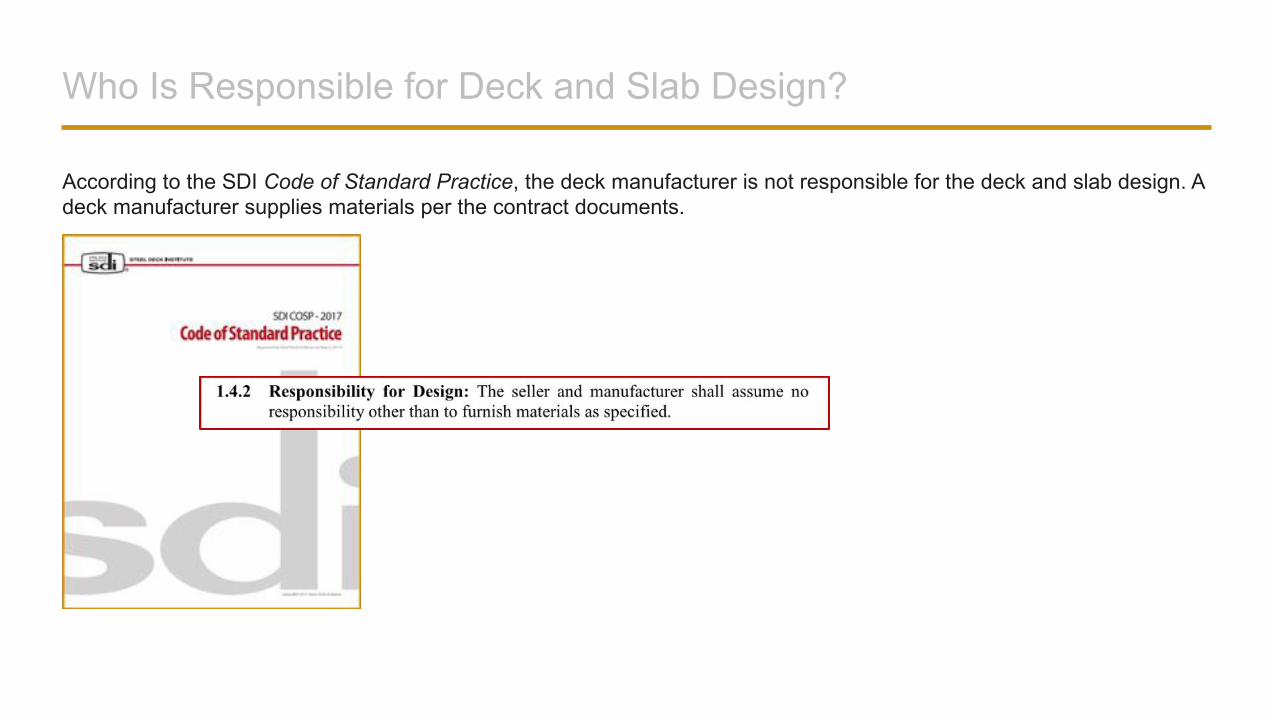
According to the SDI Code of Standard Practice, the deck manufacturer is not responsible for the deck and slab design. A deck manufacturer supplies materials per the contract documents.
Can Motorized Concrete Finishers Be Used on the Deck?
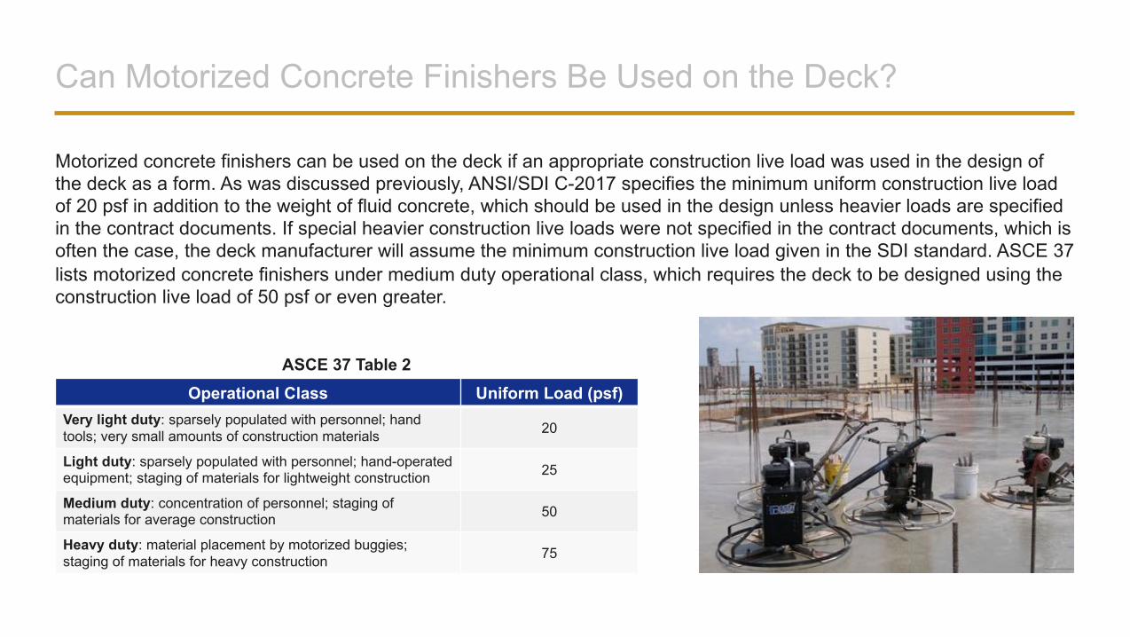
Motorized concrete finishers can be used on the deck if an appropriate construction live load was used in the design of the deck as a form. As was discussed previously, ANSI/SDI C-2017 specifies the minimum uniform construction live load of 20 psf in addition to the weight of fluid concrete, which should be used in the design unless heavier loads are specified in the contract documents. If special heavier construction live loads were not specified in the contract documents, which is often the case, the deck manufacturer will assume the minimum construction live load given in the SDI standard. ASCE 37 lists motorized concrete finishers under medium duty operational class, which requires the deck to be designed using the construction live load of 50 psf or even greater.
Operational Class Uniform Load (psf)Very light duty: sparsely populated with personnel; hand tools; very small amounts of construction materials 20
Light duty: sparsely populated with personnel; hand-operated equipment; staging of materials for lightweight construction 25
Medium duty: concentration of personnel; staging of materials for average construction 50
Heavy duty: material placement by motorized buggies; staging of materials for heavy construction 75
ASCE 37 Table 2
When Can Shoring Be Removed?
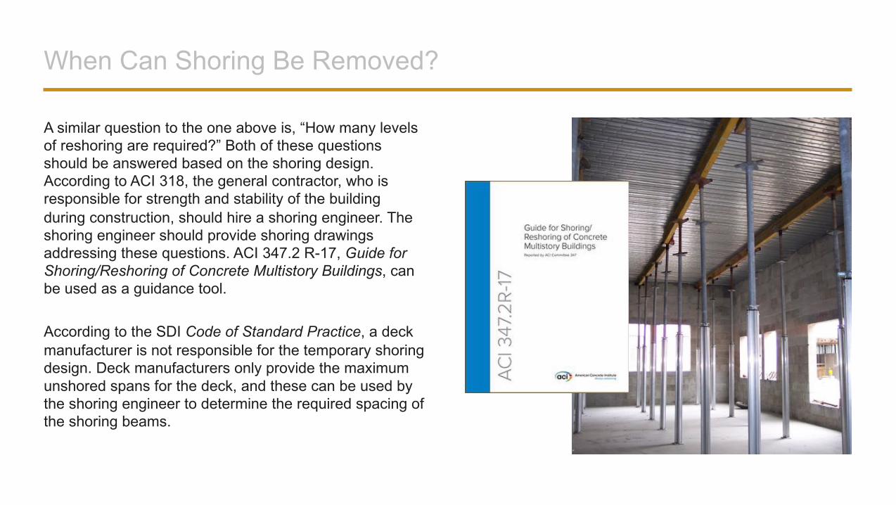
A similar question to the one above is, “How many levels of reshoring are required?” Both of these questions should be answered based on the shoring design. According to ACI 318, the general contractor, who is responsible for strength and stability of the building during construction, should hire a shoring engineer. The shoring engineer should provide shoring drawings addressing these questions. ACI 347.2 R-17, Guide for Shoring/Reshoring of Concrete Multistory Buildings, can be used as a guidance tool.
According to the SDI Code of Standard Practice, a deck manufacturer is not responsible for the temporary shoring design. Deck manufacturers only provide the maximum unshored spans for the deck, and these can be used by the shoring engineer to determine the required spacing of the shoring beams.
Where and How Can Construction Joints Be Provided?
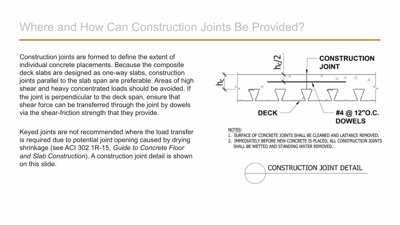
Construction joints are formed to define the extent of individual concrete placements. Because the composite deck slabs are designed as one-way slabs, construction joints parallel to the slab span are preferable. Areas of high shear and heavy concentrated loads should be avoided. If the joint is perpendicular to the deck span, ensure that shear force can be transferred through the joint by dowels via the shear-friction strength that they provide.
Keyed joints are not recommended where the load transfer is required due to potential joint opening caused by drying shrinkage (see ACI 302.1R-15, Guide to Concrete Floor and Slab Construction). A construction joint detail is shown on this slide.
Can Man Lifts Be Used on the Slab?
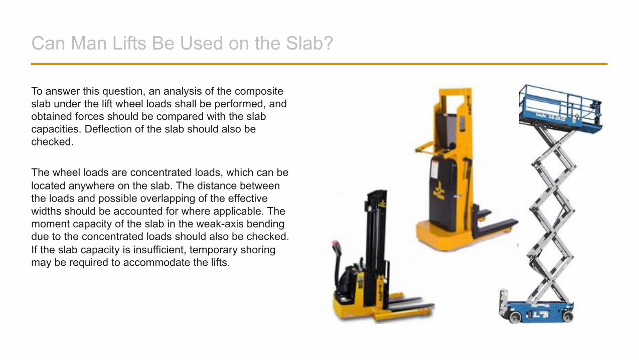
To answer this question, an analysis of the composite slab under the lift wheel loads shall be performed, and obtained forces should be compared with the slab capacities. Deflection of the slab should also be checked.
The wheel loads are concentrated loads, which can be located anywhere on the slab. The distance between the loads and possible overlapping of the effective widths should be accounted for where applicable. The moment capacity of the slab in the weak-axis bending due to the concentrated loads should also be checked. If the slab capacity is insufficient, temporary shoring may be required to accommodate the lifts.

Conclusion
©2019 New Millennium Building Systems. The material contained in this course was researched, assembled, and produced by New Millennium Building Systems and remains its property.
For more information, visit: www.newmill.com