Embed Size (px)
Citation preview
Design of large underground caverns for hydroelectric projects with
particular reference to structurallycontrolled failure mechanisms
R.D. Hammett and E. Hoek
Paper presented at ASCE Spring Convention, New YorkSession on Rock Mechanics of Large Hydro Projects
May 12, 1981
1981 Hammet and Hoek on underground caverns
2
Design of large underground caverns for hydroelectric projects withparticular reference to structurally controlled failure mechanisms
Abstract
Two distinct types of failures occur in the roof and walls of excavations in rock. Inweak or very heavily jointed rock or in massive hard rock subjected to very highstress, failure of the rock mass surrounding the excavation is the dominant failuremode. In hard rock excavations at shallow depth, gravity controlled falling or slidingof blocks or wedges defined by intersecting structural discontinuities is the mostcommon type of failure. In the former case, support by means of pattern bolting withshotcrete and mesh is the most common means of stabilizing the excavation with steelsets or concrete lining being used in extreme cases. In the case of structurallycontrolled failures, rock bolts or cables designed to support the weight of individualblocks or wedges are generally the most effective and economical form of support.
The differences between these two types of rock mass failure is examined and someof the practical aspects of underground excavation design involving these types offailure are discussed.
Introduction
Geotechnical engineers involved in the design of support for underground excavationsare faced with the perplexing problem of deciding upon a suitable design approach.Developments in underground support design have included the use of rock massclassification systems (Barton, Lien and Lunde, 1974; Bieniawski, 1974), analytical-observational approaches such as the New Austrian Tunnelling Method (Rabcewicz,1964), support-interaction concepts (Ladanyi, 1974; Hoek & Brown, 1980), anddesigns based upon structurally controlled failure mechanisms (Hoek, 1977; Croneyet al., 1978). Combining these designs approaches with well documented casehistories (Cording et al., 1971) means that the design engineer has access to a wealthof experience. However, the design engineer is still faced with the critical problem ofmatching the most appropriate design approach to the rock conditions and ofrecommending the most suitable design-contractual arrangement for the job.
This paper deals primarily with a specific type of underground support designproblem, namely the identification of and support design for structurally controlledfailure in hard rock excavations. This particular design approach is discussed in termsof the set of conditions to which it applies and those conditions where its use isinappropriate.
Support design philosophy in terms of rock conditions
The simplest classification of rock is to divide it into two categories of weak andstrong. Weak rock is defined as that where the strength of the rock mass is less than orequal to the induced stresses around the underground opening. Strong rock wouldhave a rock mass strength of two or three times the maximum stress around theopening. This simple classification makes the choice of support design philosophyrelatively easy although it must be realized that there are intermediate cases in which
1981 Hammet and Hoek on underground caverns
3
the choice will be less obvious.
Rock masses may be weak because the strength of the component materials is low orbecause the rock mass is very highly jointed. In either case, the weak rock masssurrounding an underground opening requires uniform support such as that providedby a regular pattern of rock bolts accompanied by mesh-reinforced shotcrete. Supportpressures, bolt spacings and shotcrete thicknesses are usually based upon precedentdesign practice with an increasing tendency to use rock mass classification systems toprovide a rational basis for the choice of the most appropriate values. Analysis of thestresses induced around the opening can be used to identify critical zones in whichadditional support of pre-placed support is required to improve stability. The responseof the rock mass to the excavation sequence and the acceptance of load by the supportsystem is particularly important and the rock -support interaction concept (Ladanyi,1974; Hoek & Brown, 1980) can be used as a guide in the overall support design. Inweak rock, underground excavation stability is generally controlled by failure of therock mass and structurally controlled failures of significant size are rare.
An example of underground excavation design in weak rock is that for theDrakensberg Pumped Storage Scheme in South Africa (Bowcock et al., 1977). Weakhorizontally bedded mudstones, siltstones and sandstones are supported by patternbolting and mesh reinforced shotcrete. In this case, structurally controlled failureswere not significant and were not considered in the design.
At the opposite end of the spectrum are excavations in strong rock masses. In thesecases, not only is the intact rock strong but the spacing of joints is relatively large.Under these circumstances, the stability of the rock mass surrounding theunderground openings is generally controlled by structural failure mechanisms. TheDinorwic Pumped Storage Scheme in Wales and the Rio Grande Pumped StorageProject in Argentina are typical examples of large excavations (20 m and 25 m cavernspans respectively) excavated in strong rock (Douglas et al., 1977).
In the case of excavations in strong rock, blocks or wedges defined by intersectingstructural features can either fall from the roof or slide from the roof or walls. Theexcavation designer has the choice of supporting individual blocks or wedges withspecifically designed reinforcement (referred to here as structural bolting), acombination of structural bolting and pattern bolting or, in some cases, pattern boltingonly.
The choice of a suitable design philosophy in weak and strong rocks tends to berelatively simple as compared to that required for intermediate strength rocks in whichall of the failure mechanisms discussed earlier in this paper can occur. In such cases, acombination of several different support methods may be required and the choice ofthe optimum combination involves a great deal more judgement than the extremecases of weak or strong rock. Having said this, the design engineer should still make aconcerted effort to identify the role of support in different locations around theexcavation boundary. Failure to do this makes it very difficult to judge theeffectiveness of the design and to intelligently interpret the results from anymonitoring system installed in the excavation.
1981 Hammet and Hoek on underground caverns
4
Support design philosophy in terms of contractual arrangements andengineering supervision during excavation
The design of pattern bolting to support excavations in weak rock can be done prior tothe commencement of excavation and changes in this pattern as excavation proceedsare likely to be relatively minor. Under these circumstances, traditional contractualarrangements developed for shallow tunneling can be applied without too muchdifficulty. The same is not necessarily true in the case of excavations in strong rock inwhich it may not be possible to design an effective support system in advance of theexcavation and where traditional contractual arrangements may not be appropriate.The remainder of this paper deals with the design of support for excavations in strongrock and explores some of the options which are available to the design engineer.
The first major decision to be made prior to commencing the excavation is the level ofgeotechnical investigation required to provide preliminary design data. Thepreliminary investigations typically involve regional geology studies, mapping ofsurface outcrops and geological data collection from core drilling from surface. In thecase of strong rock sites, these preliminary investigations should be aimed atobtaining information on major structural features such as faults which may intersectthe excavations. The orientation, width and shear strength of these major features willhave a significant influence on the stability of the openings intersected by them.
Samples form diamond core drilling can be utilized to determine the intact strength ofthe rock, the shear strength of joints on a small scale and the dips and dip directions ofsignificant joint sets (this latter set of measurements may require the use of specialcore orientation techniques). The orientation of the major structural features togetherwith the dips and dip directions of the joints can be used as a basis for optimizing theorientation of the excavations. Because of the constraints imposed by hydraulic andother non- geotechnical considerations, it is unlikely that the major excavations can becompletely re-oriented to achieve maximum structural stability. However, evenrelatively minor re-orientation can sometimes result in significant improvements instability and hence savings in support costs. With the exception of major faults, it isvery difficult to trace specific structural features from one borehole to the next, almostirrespective of how close the holes are to one another. This means that a completethree-dimensional structural model cannot be established prior to the commencementof excavation. Prominent joint orientations can be defined but specific blocks cannotbe identified. Hence, at least for excavations in strong rock, a surface drilling programquickly reaches a state of diminishing returns in terms of useful information recoveredfor the money spent. This money can often be directed more profitably towardsincreasing the engineering input into the excavation phase and finalizing the detaileddesign as the excavation proceeds. Expressing this in simpler terms, the explorationprogram prior to excavation should be directed towards defining the general rockconditions and specific major fault-related problems. These studies are particularlyimportant in terms of estimating overall project costs but, having achieved this, thesurface investigation program may well be suspended in favour of assessing thedetailed support requirements on a ‘design-as-you-go’ basis.
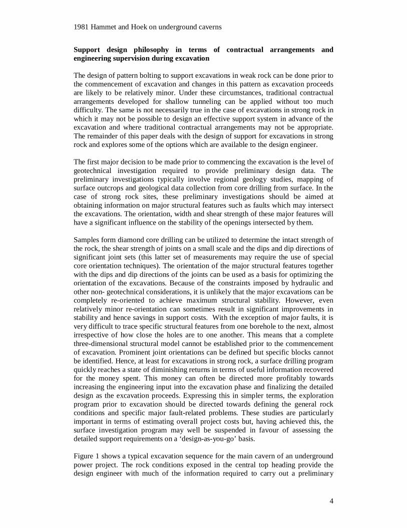
Figure 1 shows a typical excavation sequence for the main cavern of an undergroundpower project. The rock conditions exposed in the central top heading provide thedesign engineer with much of the information required to carry out a preliminary
1981 Hammet and Hoek on underground caverns
5
design of the detailed support requirements for the remainder of the cavern. It isimportant that as much flexibility as possible be retained during the subsequentexcavations in case the projections made on the basis of the observations in the pilotheading prove to be inaccurate and the support design has to be changed toaccommodate specific local conditions.
Figure 1. Excavation stages for cavern
1981 Hammet and Hoek on underground caverns
6
In the ‘design-as-you-go’ approach, the pilot heading becomes an importantcomponent in the design process. Significant structural features should be mapped toidentify specific blocks or wedges which are potentially unstable and which requiresupport as they are progressively exposed during the subsequent excavation stages.
The techniques involved in mapping the roof and walls of the pilot heading and ofprojecting the mapped structural features onto the as yet unexcavated boundaries inorder to determine the areas of potential instability, have been discussed by Croney etal. (1978). These techniques were used in the design of support for the mainexcavations of the Dinorwic Pumped Storage Scheme in Wales.
The ‘design-as-you-go’ approach was also found to provide a very efficient andeconomical basis for support design in the Rio Grande Pumped Storage Scheme inArgentina. The support design for the roof and walls of the main cavern was basedsolely on the need to support specific blocks or wedges. Pattern bolting was only usedin some local areas of closely spaced jointing.
It should be noted that in spite of its many advantages, the ‘design-as-you-go’approach may not be suitable for all excavations in strong rock. It requires acompetent team of design engineers to be on site for most of the excavation phase andfor them to work intimately with the contractor. In most cases, the mapping and boltinstallation procedures need to be integrated directly into the excavation cycle. Insome instances, temporary support requirements need to be estimated by the designengineer at the face and be installed immediately after the mucking cycle. Thesedesign estimates can be checked later and additional support can be installed ifrequired. As discussed later, the analyses are not particularly complicated and requirea knowledge of the orientation of the discontinuities defining the block, the unitweight of the rock, and the shear strength of the discontinuities. The analysis canreadily be performed with the aid programmable calculators.
The ‘design-as-you-go’ approach also requires a very flexible contractual agreementbetween the contractor and the owner. Bolt lengths and diameters obviously need tobe standardized to allow for efficient manufacture, but the final decision on boltlocation and size needs to be made by the on-site design engineer. Similarly, theheading size needs to conform to the size of the blast hole drilling equipment but thereneeds to be enough flexibility for the design engineer to recommend decreasing thepilot heading size when the rock conditions are poor and increasing it again when therock improves.
If a ‘design-as-you-go’ approach is considered inappropriate, possible for the reasonsdiscussed earlier, the alternative is to design a regular bolting pattern which willprovide adequate support for potentially unstable blocks, irrespective of whether ornot these blocks are actually exposed in the roof or walls. A safe approach, althoughone that may be very conservative, is to determine, from the surface drilling program,the orientation of the discontinuities in the rock mass and assume that these arecontinuous and can occur at the worst possible location forming the maximum sizedblock for the opening. This is often referred to as the ubiquitous joint approach and asuitable bolt pattern can be designed to ensure the support of this maximum sizedblock. It is very unlikely that this maximum sized block will in fact be present,although geometrically similar smaller blocks may occur.
1981 Hammet and Hoek on underground caverns
7
The most significant advantage of the pattern bolt approach is that the design can befinalized prior to commencing the excavation and the only supervision required is tomaintain quality control of the installation of the support. As noted earlier, thedisadvantage is that depending on the exact size and location of blocks, the design islikely to be very conservative. A combination of pattern bolting and structural boltingmay in some cases prove to be a useful compromise, although the stability of blocksshould be assessed soon after excavation to determine if the pattern bolting providessufficient support or if additional structural bolting is required.
The structural support that has been described in the preceding discussions refers tomajor structural blocks. In addition, local support of the rock at the boundary of theexcavation, which is often quite loose from blast damage or from small blocks havingfallen out, is required. This can be achieved in most cases by pattern bolting betweenthe structural bolts with short, low strength-capacity bolts, combined with meshreinforced shotcrete.
Identification of structural failure mechanisms
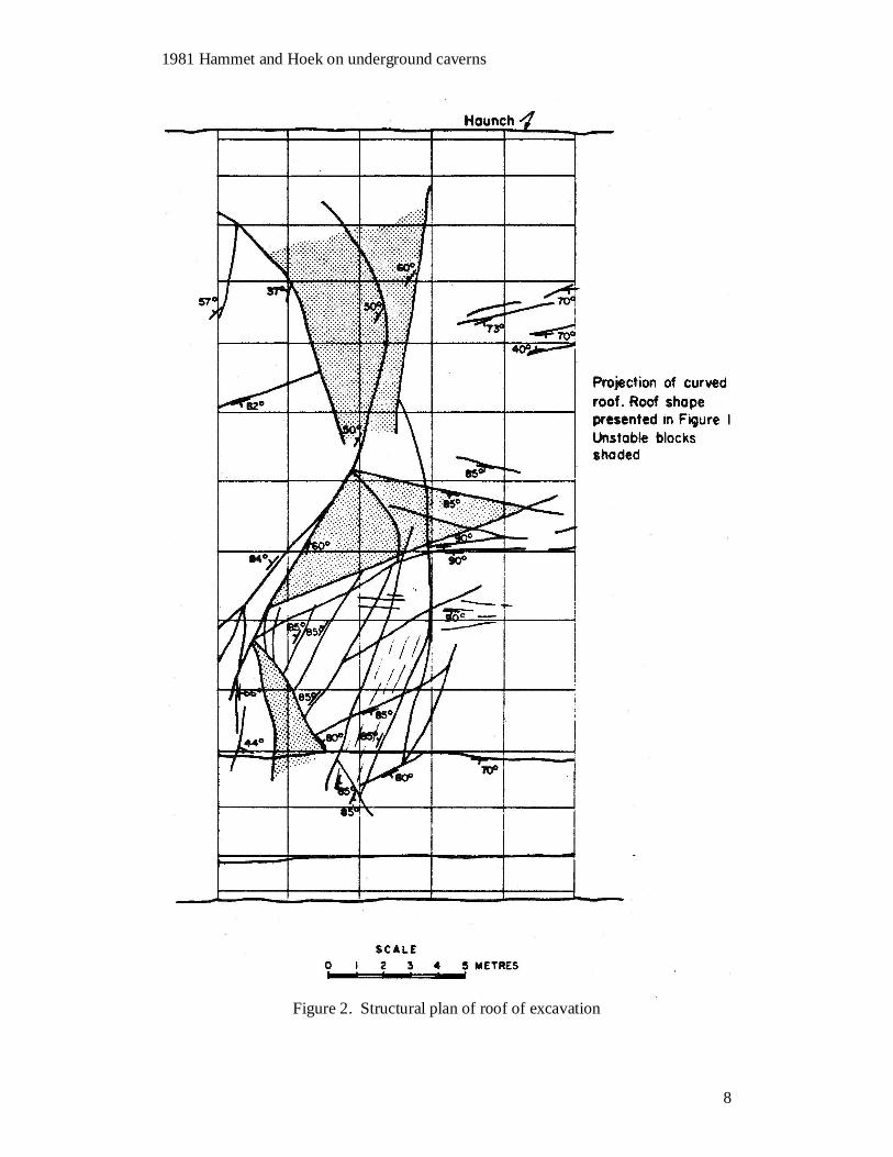
The onus falls on the design engineer to identify potential failure mechanisms ofblocks falling and sliding from the roof and walls of the excavation. This cansometimes be done by visual observation at the excavation face but shouldsubsequently be checked after a detailed map of the discontinuities has been prepared,to ensure that none have been missed. This map should show the dip and dip directionof all faults and joints and the surveyed location of their traces on the excavationboundary. Figure 2 shows a typical structural map of part of the curve roof of a largeexcavation and identifies potential unstable blocks.
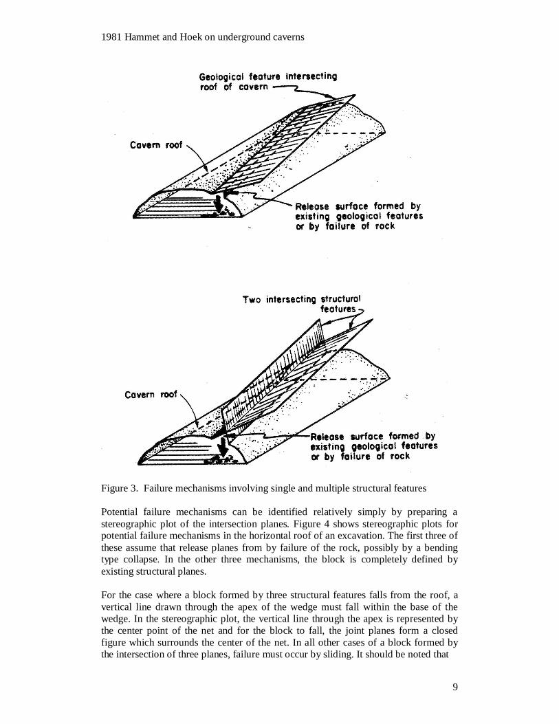
The minimum number of structural planes required to completely define a block isthree, with the fourth plane of the block being the boundary of the excavation.Failures can occur involving one or two structural features if it is assumed that releasesurfaces are formed by failure of the rock or by the presence of minor structuralweaknesses. Failure mechanisms with one or two structural features, and assumedrelease planes, are shown in Figure 3. Release planes form more readily if the mainstructural features are continuous over a considerable length, and failures of this typeare often associated with faults, particularly where faults intersect the excavation at arelatively shallow angle.
Blocks defined by three structural planes can either fall or slide from the roof or slidefrom the walls. Sliding can occur on one plane with the other two planes acting as therelease planes, or slide on the intersection of two planes with the third plane acting asthe release plane. As discussed by Croney et al. ( 1978), blocks can also be formed bymore than three structural planes, although this is not very common and will not bediscussed further in this paper.
1981 Hammet and Hoek on underground caverns
8
Figure 2. Structural plan of roof of excavation
1981 Hammet and Hoek on underground caverns
9
Figure 3. Failure mechanisms involving single and multiple structural features
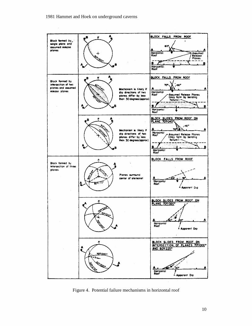
Potential failure mechanisms can be identified relatively simply by preparing astereographic plot of the intersection planes. Figure 4 shows stereographic plots forpotential failure mechanisms in the horizontal roof of an excavation. The first three ofthese assume that release planes from by failure of the rock, possibly by a bendingtype collapse. In the other three mechanisms, the block is completely defined byexisting structural planes.
For the case where a block formed by three structural features falls from the roof, avertical line drawn through the apex of the wedge must fall within the base of thewedge. In the stereographic plot, the vertical line through the apex is represented bythe center point of the net and for the block to fall, the joint planes form a closedfigure which surrounds the center of the net. In all other cases of a block formed bythe intersection of three planes, failure must occur by sliding. It should be noted that
1981 Hammet and Hoek on underground caverns
10
Figure 4. Potential failure mechanisms in horizontal roof
1981 Hammet and Hoek on underground caverns
11
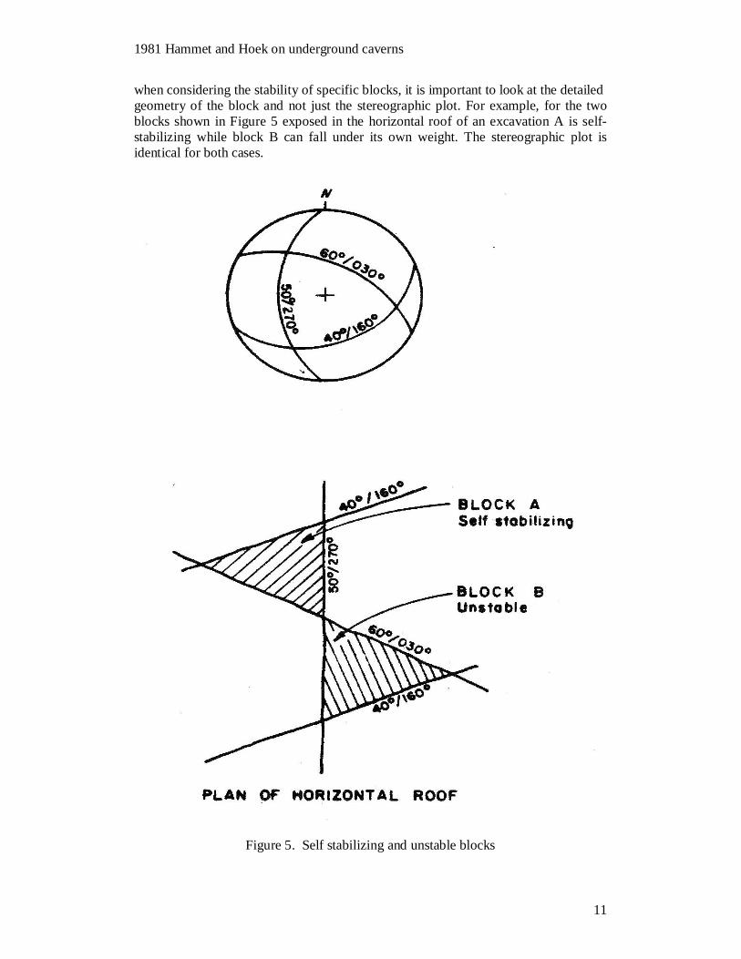
when considering the stability of specific blocks, it is important to look at the detailedgeometry of the block and not just the stereographic plot. For example, for the twoblocks shown in Figure 5 exposed in the horizontal roof of an excavation A is self-stabilizing while block B can fall under its own weight. The stereographic plot isidentical for both cases.
Figure 5. Self stabilizing and unstable blocks
1981 Hammet and Hoek on underground caverns
12
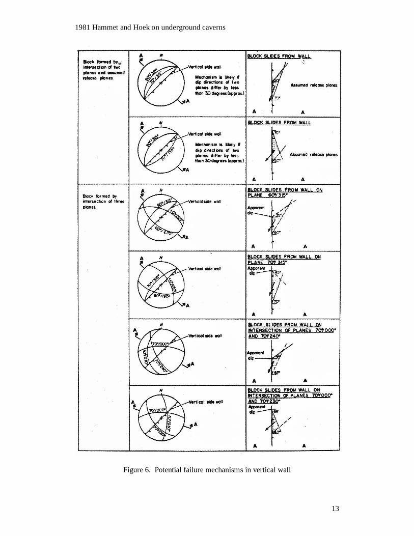
Figure 6 shows possible failure mechanisms is the wall of an excavation, the wallbeing oriented at 30 degrees east of north. The wall presented in the figure is theeastern wall, and potential failure mechanisms in the western wall are mirror imagesof those in the east wall. The mechanisms involve either sliding on a single plane oralong the intersection of two planes. The first two mechanisms assume that releaseplanes form by failure of the rock, possibly by a bending type collapse. In the otherfour mechanisms, the block is completely defined by existing structural planes.Assessing potential failure mechanisms for an inclined wall or roof follows the samegeneral principles outlined above.
Roof and sidewall failure analysis
From the stereographic plots shown in Figures 4 and 6, it is possible to determine ifthere is a potential for block failure. In the case of a block falling from the roof, nofurther stability analysis is required except to calculate the weight of the block anddetermine the required bolt capacity to support it. A factor of safety of between 1.5and 2.0 is recommended, depending on the quality of the bolt installation. The weight
of the block can be calculated graphically or analytically by methods described indetail by Hoek and Brown (1980).
For blocks which slide from the roof or walls of the excavation, the stereographic plotis used to determine if there is a potential failure mechanism but the actual stabilitydepends primarily on the orientation of the direction of sliding and the shear strengthof the sliding surfaces. Sliding is either on a single plane or along the line ofintersection of two planes.
If it is assumed that the sliding surface has a linear frictional strength with zerocohesion, sliding can only occur if the plane or the line of intersection along whichsliding is to occur is steeper than the angle of friction.
It should be remembered in assessing the shear strength of the surfaces on whichsliding takes place that the normal stresses on these planes, as a result of the weight ofa typical block, are quite small. This means that a small degree of roughness of theplanes may result in a high equivalent frictional strength. If the frictional strength isassessed fro direct shear tests, the normal stress at which the tests are performedshould be correspondingly low in order to interpret the results correctly.
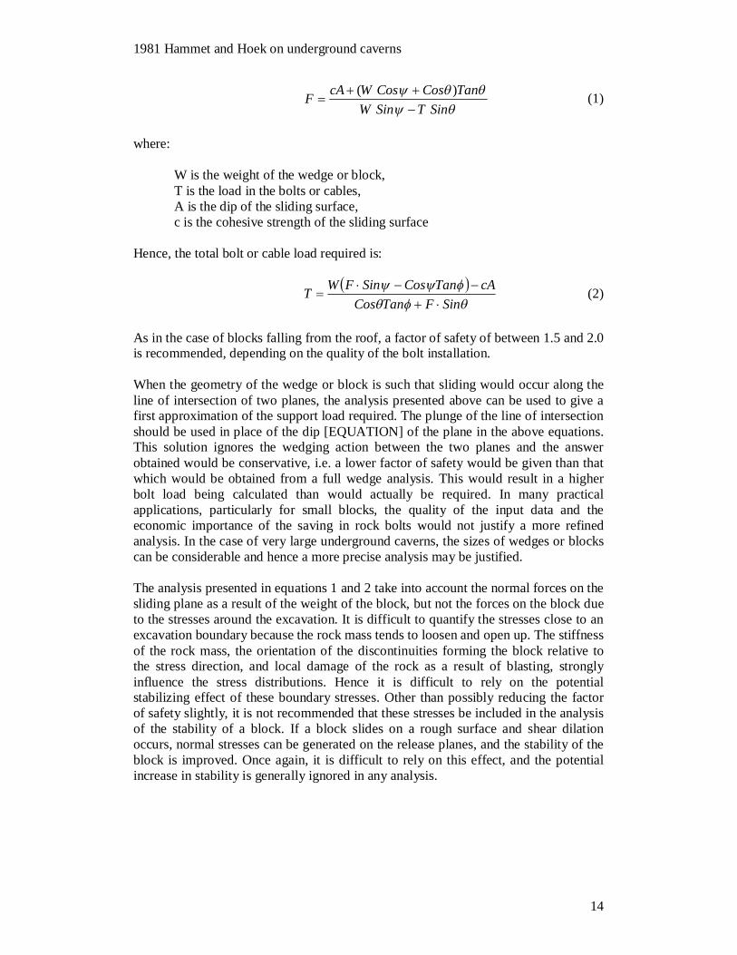
For the case of a sliding block, once the trace length of one of the discontinuities oralternatively the maximum span or height of the exposed face (the ubiquitous case) isknown, the detailed block geometry can be determined graphically or analytically bymethods described in detail by Hoek and Brown (1980). The block geometry allowsthe weight of the block and the orientation of the sliding surface to be determined,from which the factor of safety against sliding can be calculated. For sliding on asingle plane with two other intersecting planes acting as release planes, the factor ofsafety is given by:
1981 Hammet and Hoek on underground caverns
13
Figure 6. Potential failure mechanisms in vertical wall
1981 Hammet and Hoek on underground caverns
14
SinTSinWTanCosCosWcAF )( (1)
where:
W is the weight of the wedge or block,T is the load in the bolts or cables,A is the dip of the sliding surface,c is the cohesive strength of the sliding surface
Hence, the total bolt or cable load required is:
SinFTanCoscATanCosSinFWT (2)
As in the case of blocks falling from the roof, a factor of safety of between 1.5 and 2.0is recommended, depending on the quality of the bolt installation.
When the geometry of the wedge or block is such that sliding would occur along theline of intersection of two planes, the analysis presented above can be used to give afirst approximation of the support load required. The plunge of the line of intersectionshould be used in place of the dip [EQUATION] of the plane in the above equations.This solution ignores the wedging action between the two planes and the answerobtained would be conservative, i.e. a lower factor of safety would be given than thatwhich would be obtained from a full wedge analysis. This would result in a higherbolt load being calculated than would actually be required. In many practicalapplications, particularly for small blocks, the quality of the input data and theeconomic importance of the saving in rock bolts would not justify a more refinedanalysis. In the case of very large underground caverns, the sizes of wedges or blockscan be considerable and hence a more precise analysis may be justified.
The analysis presented in equations 1 and 2 take into account the normal forces on thesliding plane as a result of the weight of the block, but not the forces on the block dueto the stresses around the excavation. It is difficult to quantify the stresses close to anexcavation boundary because the rock mass tends to loosen and open up. The stiffnessof the rock mass, the orientation of the discontinuities forming the block relative tothe stress direction, and local damage of the rock as a result of blasting, stronglyinfluence the stress distributions. Hence it is difficult to rely on the potentialstabilizing effect of these boundary stresses. Other than possibly reducing the factorof safety slightly, it is not recommended that these stresses be included in the analysisof the stability of a block. If a block slides on a rough surface and shear dilationoccurs, normal stresses can be generated on the release planes, and the stability of theblock is improved. Once again, it is difficult to rely on this effect, and the potentialincrease in stability is generally ignored in any analysis.
1981 Hammet and Hoek on underground caverns
15
Conclusions
In summary, it is important for the design engineer to understand the role the supportthat is installed to ensure the stability of underground excavations. In weak rockmasses, rock bolts are installed to stitch together the rock where the stresses haveexceeded the strength so that this rock is held in place. This failed rock has a reduced,but nevertheless finite strength, and this can generate confining stresses which helpstabilize the remainder of the rock mass around the excavation. In strong rock masses,stability is often controlled by intersecting discontinuities which form blocks whichcan either fall or slide from the roof of an excavation or slide from the walls. Rockbolts can be used to support these potential failure mechanisms.
In cases where structural instabilities dominate the support requirements for largeunderground excavations, it is often difficult to design the support in advance of theexcavation. The location, orientation and continuity of features in the roof and wall ofan excavation can rarely be determined from surface drilling. An alternative approachis to carry out a modest exploration program in advance of the excavation and assessthe detailed support requirements as the excavation proceeds. This ‘design-as -you-go’ philosophy requires a very flexible contractual agreement between the contractorand the owner and a competent support design team to assess the stability and supportrequirements after each blast. This design team is responsible for identifyingpotentially unstable blocks and providing adequate support to ensure the stability ofthe excavation.
List of references
Barton, N.R., Lien, R. and Lunde, 1974. J. Engineering classification of rock massesfor the design of tunnel support. Rock Mechanics. Vol. 6, No. 4, pages 189-236.
Bieniawski, Z.T. Geomechanics classification of rock masses, 1974. Proc. ThirdInternational Congress of Rock Mechanics, ISRM, Denver, Vol. 11A, pages 27-32.Bowcock, J.B., Boyd, J.M., Hoek, E. and Sharp, J.C. Drakensberg Pumped StorageScheme - rock engineering aspects. Proc. Symposium on Exploration for RockEngineering, Johannesburg. A.A. Balkema, Rotterdam, 1977, Vol. 2, pages 121-139.
Cording, E.J., Hendron, A.J. and Deere, D.V. 1971. Rock engineering forunderground caverns. Proc. Symposium on Underground Rock Chambers, Pheonix,ASCE, pages 407-486.
Croney, P., Legge, T.F. and Dhalla, A. 1978. Location of block release mechanismsin tunnels from geological data and the design of associated support. ComputerMethods in Tunnels Design, The Institution of Civil Engineers, London, pages 97-119.
Douglas, T.H., Richards, L.R. and O’Niel, D. 1977. Site investigations for the mainunderground complex - Dinorwic Pumped Storage Scheme. Field Measurements inRock Mechanics. A.A. Balkema, Rotterdam, Vol. 2, pages 551-567.
Hoek, E. and Brown, E.T. 1980. Underground Excavation in Rock, Institution of
1981 Hammet and Hoek on underground caverns
16
Mining and Metallurgy, 527 pages.
Hoek, E. Structurally controlled instability in underground excavations. 1977. Proc.19th Rock Mechanics Symposium, Keystone, Colorado.
Ladanyi, B. Use of the long term strength concept in the determination of groundpressure on tunnel linings. Proc. Third International Congress on Rock Mechanics,ISRM, Denver, 1974, Vol. IIB, pages 1150-1156.
Rabcewicz, L.V. 1964 and 1965. The New Austrian tunneling method. Water Power,Part 1, Vol. 16, 1964, pages 453-457 and Part III, Vol. 17,1965, pages 19-24.