Embed Size (px)
Citation preview

________________________________________________________________________0
Design of Interface Selection Protocols for Multi-homed Wireless Networks
A thesis submitted in partial fulfilment of the requirements for the degree of Doctor of
Philosophy (Ph.D.) to:
Electronic and Computer Engineering Division,
School of Engineering and Design,
Brunel University,
United Kingdom.
by:
Zina Jerjees
Supervised By:
Prof Hamed Al-Raweshidy
2009/2010
Abstract _________________________________________________________________________
________________________________________________________________________I
Abstract
The IEEE 802.11/802.16 standards conformant wireless communication stations have multi-homing
transmission capability. To achieve greater communication efficiency, multi-homing capable stations use
handover mechanism to select appropriate transmission channel according to variations in the channel quality.
This thesis presents three internal-linked handover schemes, (1) Interface Selection Protocol (ISP), belonging to
Wireless Local Area Network (WLAN)- Worldwide Interoperability for Microwave Access (WiMAX) environment
(2) Fast Channel Scanning (FCS) and (3) Traffic Manager (TM), (2) and (3) belonging to WiMAX Environment.
The proposed schemes in this thesis use a novel mechanism of providing a reliable communication route. This
solution is based on a cross-layer communication framework, where the interface selection module uses
various network related parameters from Medium Access Control (MAC) sub-layer/Physical Layer (PHY) across
the protocol suite for decision making at the Network layer. The proposed solutions are highly responsive
when compared with existing multi-homed schemes; responsiveness is one of the key factors in the design of
such protocols. Selected route under these schemes is based on the most up to date link-layer information.
Therefore, such a route is not only reliable in terms of route optimization but it also fulfils the application
demands in terms of throughput and delay.
Design of ISP protocol use probing frames during the route discovery process. The 802.11 mandates
the use of different rates for data transmission frames. The ISP-metric can be incorporated into various routing
aspects and its applicability is determined by the possibility of provision of MAC dependent parameters that
are used to determine the best path metric values. In many cases, higher device density, interference and
mobility cause variable medium access delays. It causes creation of ‘unreachable zones’, where destination is
marked as unreachable. However, by use of the best path metric, the destination has been made reachable,
anytime and anywhere, because of the intelligent use of the probing frames and interface selection algorithm
implemented. The IEEE 802.16e introduces several MAC level queues for different access categories,
maintaining service requirement within these queues; which imply that frames from a higher priority queue,
i.e. video frames, are serviced more frequently than those belonging to lower priority queues. Such an
enhancement at the MAC sub-layer introduces uneven queuing delays. Conventional routing protocols are
unaware of such MAC specific constraints and as a result, these factors are not considered which result in
channel performance degradation. To meet such challenges, the thesis presents FCS and TM schemes for
WiMAX. For FCS, Its solution is to improve the mobile WiMAX handover and address the scanning latency.
Since minimum scanning time is the most important issue in the handover process. This handover scheme
aims to utilize the channel efficiently and apply such a procedure to reduce the time it takes to scan the
neighboring access stations. TM uses MAC and physical layer (PHY) specific information in the interface metric
and maintains a separate path to destination by applying an alternative interface operation. Simulation tests
and comparisons with existing multi-homed protocols and handover schemes demonstrate the effectiveness
of incorporating the medium dependent parameters. Moreover, show that suggested schemes, have shown
better performance in terms of end-to-end delay and throughput, with efficiency up to 40% in specific test
scenarios.

Acknowledgements ________________________________________________________________________
II
Acknowledgments
First and foremost, I would like to express my gratitude to my colleagues, friends and
family who all supported me during the course of my PhD. Furthermore, I would like to
especially thank Prof. Hamed AL-Raweshidy, who initially encouraged me to undertake this
project, and provided invaluable support throughout its duration. Your friendship and
assistance has been most appreciated, and especially at the crucial times when problems
and challenges were inevitably faced. I would like to thank all my colleagues at the WNCC
who had been of tremendous help and support. I would like to acknowledge all of the staff
at Brunel University. Their encouraging and supportive attitudes as well as their professional
conduct all help to promote and advance research.
Finally, I would like to thank my parents, sisters and brother who had been a source
of motivation and strength during this course of time.

List of Tables _________________________________________________________________________
________________________________________________________________________III
Table of Contents
Chapter 1: Introduction ... . . . . . . . . . . . . . . . . . . . . . . . . . . . . . . . . . . . . . . . . . . . . . . . . . . . . . . . . . . . . . . . . . . . . . . 1
1.1 Background and Motivation ................................................................................................ 1
1.2 Research Challenges ............................................................................................................ 3
1.3 Contributions of the Thesis ................................................................................................. 4
1.4 Organization of Thesis ......................................................................................................... 7
1.5 References ........................................................................................................................... 8
Chapter 2: INTRODUCTION TO IEEE 802.11 AND IEEE 802.16 ... . . . . . . . . . . . . . . . . . . 9
2.1 Introduction ......................................................................................................................... 9
2.2 IEEE 802.11 (WLAN) Network ........................................................................................... 10
2.3 IEEE 802.11 (WLAN) Connectivity ..................................................................................... 10
2.4 Classification according to the coverage area .................................................................. 12
2.4.1 Classification According to Mobility Support ................................................................. 15
2.4.1.1 Single Homed network ................................................................................................ 16
2.4.1.2 Multi-Homed Network ................................................................................................ 16
2.5 Multi-Homed Network Characteristics ........................................................................... 17
2.6 Worldwide Interoperability for Microwave Access (WiMAX) ........................................... 18
2.6.1 Mobile WiMAX ............................................................................................................... 19
2.7 Mobile WiMAX Features ................................................................................................... 20
2.8 Quality of Service (QoS) Support ....................................................................................... 21
2.8.1 Physical Layer ................................................................................................................. 22
2.8.1.1 OFDMA Basics ............................................................................................................. 23
2.8.1.2 TDD Frame Structure ................................................................................................... 24
2.8.1.3 Video Coding Technique ............................................................................................. 26
2.8.2 MAC Layer ...................................................................................................................... 28

List of Tables ________________________________________________________________________
IV
2.8.2.1 MAC Sublayers ............................................................................................................ 29
2.9 Mobility Support ............................................................................................................... 31
2.9.1 Handover in WiMAX ....................................................................................................... 31
2.10 Summary ......................................................................................................................... 36
2.11 References ....................................................................................................................... 37
Chapter 3: RELATED WORK ... . . . . . . . . . . . . . . . . . . . . . . . . . . . . . . . . . . . . . . . . . . . . . . . . . . . . . . . . . . . . . . 39
Related Work ........................................................................................................................... 39
3.1 Introduction ....................................................................................................................... 39
3.2 Mobility Support & Multi-homing Routing Protocols ....................................................... 39
3.2.1 Mobile Internet Protocol version 6 (MIPv6) .................................................................. 40
3.2.2 Stream Control Transmission Protocol (SCTP) ............................................................... 41
3.2.3 Network Mobility (NEMO) ............................................................................................. 43
3.2.4 Host Identity Protocol (HIP) ........................................................................................... 44
3.2.5 SHIM6 (Site Multihoming by IPv6 Intermediation).........................................................46
3.3 Related Work Based on Handover and Cross-Layer Solutions...........................................48
3.4 Multi-homed Networks Handover Performance Requirements ...................................... 54
Chapter 4: DESIGN OF INTERFACE SELECTION PROTOCOL (ISP) FOR IEEE
802.11 & IEEE 802.16 ... . . . . . . . . . . . . . . . . . . . . . . . . . . . . . . . . . . . . . . . . . . . . . . . . . . . . . . . . . . . . . . . . . . . . . . 59
4.1 Proposed Multi-homing Protocol ...................................................................................... 59
4.2 ISP: In Details ..................................................................................................................... 60
4.2.1 Packets Format ............................................................................................................... 60
4.2.1.1 Probe Message ............................................................................................................ 60
4.2.2 Route Parameters (QoS) ................................................................................................ 61
4.2.2.1 Available Bandwidth (Data Rate) ................................................................................ 62

List of Tables ________________________________________________________________________
V
4.2.2.2 Latency (Delay) ............................................................................................................ 63
4.2.3. Crosse Layer Design for Optimization Wireless Networks ............................................ 65
4.2.3.1 Cross-Layer Design; An overview ................................................................................ 65
4.2.3.2 Cross Layer Solution for ISP ......................................................................................... 65
4.2.3.4 Route Process .............................................................................................................. 66
4.2.3.5 Route Maintenance Mechanism ................................................................................. 68
4.3 Summary ........................................................................................................................... 72
Chapter 5: IMPLEMENTATION OF ISP IN OPNET MODELER ... . . . . . . . . . . . . . . . . . . . . 73
5.1 OPNET Modeler ................................................................................................................. 73
5.1.1 Network Domain ............................................................................................................ 74
5.1.2 Node Editor .................................................................................................................... 75
5.1.3 Process Editor ................................................................................................................. 76
5.1.4 Packet/Link Editor .......................................................................................................... 78
5.2 ISP Node Design ................................................................................................................ 79
5.2.1 ISP Node ......................................................................................................................... 79
5.2.2 ISP Process Module ........................................................................................................ 82
5.2.2.1 The Node Performance States .................................................................................... 82
5.2.2.2 Routing States ............................................................................................................. 83
5.2.2.3 Wireless –LAN- MAC-Interface (MAC layer) ............................................................. 88
5.2.2.4 WLAN- Transmission (Physical layer) ...................................................................... 88
5.3 Testing the Module ........................................................................................................... 90
5.3.1 ISP Network Design ........................................................................................................ 91
5.3.2 Mobile Node (MN) Attributes ........................................................................................ 92

List of Tables ________________________________________________________________________
VI
5.3.3 ISP Route Technique ...................................................................................................... 95
5.4 Summary ......................................................................................................................... 101
5.5 References ....................................................................................................................... 102
Chapter 6: SIMULATION RESULTS & SCENRIOS OF ISP .... . . . . . . . . . . . . . . . . . . . . . . . . 103
6.1 Introduction ..................................................................................................................... 103
6.2 Simulation Environment .................................................................................................. 104
6.2.1 Evaluation Parameters ................................................................................................. 104
6.3 Simulation Results ........................................................................................................... 105
6.3.1 Role of ISP Route Parameters ...................................................................................... 105
6.3.1.1 Route Discovery Time ............................................................................................... 105
6.3.1.2 Network Load ............................................................................................................ 107
6.3.1.3 Media Access Delay ................................................................................................... 109
6.3.1.4 Data Dropped ............................................................................................................ 111
6.3.2 Comparison Scenarios .................................................................................................. 113
6.4 Summary ......................................................................................................................... 122
Chapter 7: PROPOSED SCHEMES IN WIMAX ... . . . . . . . . . . . . . . . . . . . . . . . . . . . . . . . . . . . . . . . 124
7.1 Introduction ..................................................................................................................... 124
7.2 Contributions of the Proposed Schemes ........................................................................ 125
7.3 Criterion Effecting Handover-Analysis ............................................................................ 127
7.4 The Proposed Schemes ................................................................................................... 131
7.4.1. Fast Channel Scanning (FCS) based on Bandwidth information ................................. 131
7.4.1.1 Scanning Phase .......................................................................................................... 131
7.4.1.2 Negotiation Procedure ............................................................................................. 133
7.4.2 Traffic Manager (TM) ................................................................................................... 137

List of Tables ________________________________________________________________________
VII
7.4.2.1 TM Server Entities ..................................................................................................... 138
7.4.2.2 Routing Technique .................................................................................................... 139
7.4.2.3 WiMAX PHY/MAC Entities ......................................................................................... 143
7.4.2.4 ARQ (Auto-Retransmission Request) ........................................................................ 143
7.4.2.5 FEC (Forward Error Correction) ................................................................................. 144
7.4.2.6 WiMAX PHY/MAC at the MS Side ............................................................................. 144
7.4.2.7 TM Silent Mode ......................................................................................................... 145
7.4.2.8 WiMAX PHY/MAC At BS Side .................................................................................... 146
7.4.2.9 Channel Switching ..................................................................................................... 147
7.4.2.10 WiMAX PHY/MAC at the Correspondent Node (CN) .............................................. 148
7.4.2.11 SVC (Scalable Video Coding) ................................................................................... 148
7.4.2.12 Frame Representation............................................................................................. 150
7.4.2.13 Interface Selection Protocol Role (ISP) ................................................................... 153
7.5 Summary ......................................................................................................................... 154
7.6 References ....................................................................................................................... 155
Chapter 8: DESIGN/ANALYSIS OF PROPOSED WIMAX SCHEMES IN OPNET
MODELER ... . . . . . . . . . . . . . . . . . . . . . . . . . . . . . . . . . . . . . . . . . . . . . . . . . . . . . . . . . . . . . . . . . . . . . . . . . . . . . . . . . . . . . 156
8.1 Introduction ..................................................................................................................... 156
8.2 Simulation Model .......................................................................................................... 156
8.2.2 WiMAX - MAC-Interface (MAC layer) ........................................................................... 160
8.2.3 WiMAX- Transmission (Physical layer) ......................................................................... 162
8.2.3.1 Transmitter Node (Tx) ............................................................................................... 162
8.2.3.2 Packet Loss Modeling ................................................................................................ 164
8.2.3.3 Traffic Organization in the Interfaces ....................................................................... 164

List of Tables ________________________________________________________________________
VIII
8.2.3.4 Mobility Parameters .................................................................................................. 166
8.3 Analysis and Simulation Results ...................................................................................... 166
8.3.1 Evaluation Parameters ................................................................................................. 167
8.3.2 Analysis ......................................................................................................................... 168
8.4 Simulation Results ........................................................................................................... 171
8.4.1 Scanning Modes ........................................................................................................... 171
8.4.2 The Handover Delay (Sec) ............................................................................................ 171
8.4.3 FCS Throughput (Packets/sec) ..................................................................................... 173
8.4.4 Data Dropped During Handover (Packets/sec) ............................................................ 174
8.4.5 Throughput (Bits/sec) ................................................................................................... 175
8.4.6 Video Application End-to-End Delay (Sec) ................................................................... 176
8.4.7 Video Conferencing Average Response Time (Sec) ..................................................... 177
8.4.8 Traffic received (Packets/sec) ...................................................................................... 178
8.4.9 Queue size (packets) .................................................................................................... 179
8.4.10 Media Access Delay (sec) ........................................................................................... 180
8.5 Summary ......................................................................................................................... 181
8.6 References ....................................................................................................................... 182
Chapter 9: CONCLUSION AND FUTURE WORK ... . . . . . . . . . . . . . . . . . . . . . . . . . . . . . . . . . . . . . . . . . 183
9.1 Conclusion ....................................................................................................................... 183
9.2 FUTURE WORK ................................................................................................................ 187
List of publications ................................................................................................................ 188

List of Tables ________________________________________________________________________
IX
List of Figures
Figure 2-1: IEEE 802.11 network connectivity..............................................................................11
Figure2-2: WLAN networks taxonomy according to coverage area.............................................14
Figure 2-3: Mobile WiMAX...........................................................................................................20
Figure 2-4: WiMAX TDD Frame Structure.....................................................................................25
Figure 2-5: SVC Encode/Decode. (CIF: lowest definition, lowest resolution), (SD: Standard
Definition, medium resolution) and (HD: High Definition, highest resolution)............................27
Figure 2-6: SVC layered structure.................................................................................................28
Figure2-7: MAC sublayers model..................................................................................................29
Figure 2-8: Service-Specific Convergence Sublayer (CS)...............................................................30
Figure 2-9: Scanning and ranging procedure................................................................................33
Figure 2-10: Handover Decision and Initiation.............................................................................34
Figure 2-11: Network Re-entry.....................................................................................................35
Figure 2-12: Process of Network Entry.........................................................................................36
Figure 3-1: MIPv6 Routing............................................................................................................41
Figure 3-2: SCTP-based Network..................................................................................................43
Figure 3-3: HIP-based layer...........................................................................................................45
Figure 3-4: Shim6 layer.................................................................................................................47

List of Tables ________________________________________________________________________
X
Figure 3-5: Shim6 multiple addresses...........................................................................................48
Figure 3-6: MAC and Logical layers Queuing................................................................................52
Figure 4-1: Probe Message Format...............................................................................................61
Figure 4-2: Cross-Layer Model......................................................................................................62
Figure 4-3: Two-path Transmission algorithm diagram................................................................67
Figure 4-4: Simulated Scenario for the Route between Node A and Node B...............................68
Figure 4-5: Keep-alive Message Format.......................................................................................69
Figure 4-6: Address Selection Mechanism....................................................................................70
Figure 5-1: Star Topology in Abstract and Network Model Representations...............................73
Figure 5-2: Network Model in OPNET modeler............................................................................73
Figure 5-3: Hierarchy of Various Domains....................................................................................75
Figure 5-4: Example of Process model..........................................................................................76
Figure 5-5: Forced and unforced states in the process model editor...........................................76
Figure 5-6: ISP Node Model..........................................................................................................78
Figure 5-7: ISP Two Interfaces Node Model.................................................................................79
Figure 5-8: IP Layer Process Models............................................................................................ 79
Figure 5-9: ISP State Machine Diagram ........................................................................................82
Figure 5-10: Mobile Node Attributes ...........................................................................................83
Figure 5-11: Mobile Node's Transmitter Attributes .....................................................................87

List of Tables ________________________________________________________________________
XI
Figure 5-12: ISP Network in OPNET Modeler ...............................................................................89
Figure 5-13: Mobile Node's MIPv6 attributes ..............................................................................90
Figure 5-14: Mobile Node's MAC Layer Attributes ..................................................................... 91
Figure 5-15: ISP Route Test Scenario ...........................................................................................92
Figure 5-17: Two-Path Transmission Algorithm ...........................................................................94
Figure 5-18: Probe Message Format ............................................................................................95
Figure 5-19: Packets received at the destination.........................................................................96
Figure 5-20: Throughput in the New Path ...................................................................................97
Figure 6-1: Route Discover Time in Small Network ................................................................... 101
Figure 6-2: Route Discover Time in Large Network .................................................................. 102
Figure 6-3: Network Load in Small Network ..............................................................................103
Figure 6-4: Network Load in Large Network ..............................................................................104
Figure 6-5: Media Access Delay in Small Network .....................................................................105
Figure 6-6: Media Access Delay in Large Network .....................................................................105
Figure 6-7: Data Dropped in Small Network ..............................................................................106
Figure 6-8: Data Dropped in Large Network ..............................................................................107
Figure 6-9: Route Discovery Time in Small Network ..................................................................108
Figure 6-10: Route Discovery Time in Large Network ................................................................109

List of Tables ________________________________________________________________________
XII
Figure 6-11: Network Load in Small Network ............................................................................110
Figure 6-12: Network Load in Large Network.............................................................................111
Figure 6-13: Media Access Delay in Small Network ...................................................................112
Figure 6-14: Media Access Delay in Large Network ...................................................................113
Figure 6-15: Data Dropped in Small Network.............................................................................114
Figure 6-16: Data Dropped in Large Network............................................................................ 115
Figure 7-1: End-to-End Delay among BSs................................................................................... 121
Figure 7-2: Average Data Dropped in the Congested Medium ................................................. 122
Figure 7-3: FCS, Fast Channel Scanning Scenario........................................................................124
Figure 7-4: Scanning Phase Diagram...........................................................................................125
Figure 7-5: Negotiation Phase Diagram......................................................................................127
Figure 7-6: Total Scanning time................................................................................................. 128
Figure 7-7: TM, Traffic Manager Network..................................................................................129
Figure 7-8: Transmission to another Interface Algorithm..........................................................133
Figure 7-9: Traffic Manager Handover Diagram.........................................................................134
List of Tables ________________________________________________________________________
XIII
Figure 7-10: SDU Fragmentation............................................................................................... 136
Figure 7-11: Data Mapping into the Downlink and Uplink Slots.................................................138
Figure 7-12: Traffic Manager Framework ................................................................................. 141
Figure 7-13: Frame Representation............................................................................................142
Figure 7-14: SVC Scheduler.........................................................................................................143
Figure 7-15: Network Re-Entry Process......................................................................................145
Figure 8-1: Traffic Manager Network in OPNET Modeler...........................................................148
Figure 8-2: Mobile Station Node Model.....................................................................................150
Figure 8-3: Mobile Station Attributes.........................................................................................151
Figure 8-4: Mobile Station's Transmitter Attributes...................................................................153
Figure 8-5: Mobile Station's Transmitter Advanced Attributes..................................................153
Figure 8-6: Mobile Station's Mobility Attributes........................................................................156
Figure 8-7: Handover Delay .......................................................................................................162
Figure 8-8: Total Handover Delay ..............................................................................................163
Figure 8-9: FCS, Fast Channel Scanning Throughput ..................................................................164
Figure 8-10: Data Dropped During Handover............................................................................ 165
Figure 8-11: TM, Traffic Manager Throughput ..........................................................................166
Figure 8-12: Video Application End-to-End Delay...................................................................... 167
Figure 8-13: Video Conferencing Average Response Time........................................................ 168
Figure 8-14: Traffic received...................................................................................................... 169
Figure 8-15: Queue Size ............................................................................................................ 170
Figure 8-16: Media Access Delay................................................................................................171
List of Tables ________________________________________________________________________
XIV
List of Tables
Table 2-1: Comparison of Various Wireless Communication Technologies ......................................... 15
Table 2-2: Comparison of Various WiMAX Standards ........................................................................... 19
Table 3-1: Description of Various Delay Values .................................................................................... 63
Table 4-1: Paths Various Route Parameters .......................................................................................... 93
Table 5-1: Comparison of Various Features between ISP, MIPv6 and Shim6 ..................................... 116
Table 6-1: Frames Temporal and SNR Scalabilities Ranges ................................................................. 142
Table 7-1: Scanning Interval Definitions.............................................................................................. 161
Table 7-2: Comparison of Various Features between the Proposed Schemes and the WiMAX Standard
Scheme ................................................................................................................................................ 172

List of abbreviations ________________________________________________________________________
VIII
List of abbreviations
ALOHA Area Locations of Hazardous Atmospheres AP Access Point ARQ Auto-Retransmission Request ASCONF Address Configuration BE Best Effort BS Base Station BSS Basic Service Set BWA Broadband Wireless Access CDMA Code Division Multiple Access CN Correspondent Node CoA Care of Address CPE Customer Premise Equipment CS Service-Specific Convergence Sublayer CSMA/CA Carrier Sense Multiple Access with Collision Avoidance DHCPv6 Dynamic Host Configuration for IPv6 DL Downlink DS Distribution System DSL Digital Subscriber Line ertPS extended real time Polling Service ESP Encapsulating Security Payload FBSS Fast Base Station Switching FCH Frame Control Header FCS Fast Channel Scanning FDD Frequency Division Duplex FEC Forward Error Correction FMIPv6 Fast Handovers for MIPv6 HA Home Agent HHO Hard Handover HIP Host Identity Protocol HIT Host Identity Tag HO Handover HMIPv6 Hierarchical MIPv6 IP Internet Protocol ISP Interface Selection protocol MAC Medium Access Control MAC CPS MAC Common Part Sublayer MAN Metropolitan Area Networks MBWA Mobile Broadband Wireless Access MDHO Macro Diversity Handover MIH Media Independent Handover MIMO Multiple Input Multiple Output
List of abbreviations ________________________________________________________________________
IX
MN Mobile Node MPEG Moving Picture Experts Group MR Mobile Router MS Mobile Station NAT Network Address Translation NEMO Network Mobility NIC Network Interface Card nrtPS non real time Polling Service nSCTP SCTP Extension of NEMO OFDMA Orthogonal Frequency Division Multiple Access OFDM Orthogonal Frequency Division multiplexing PAN Personal Area Network PDA Personal Digital Assistance PDU Protocol Data Unit PHY Physical Layer QoS Quality of Service rtPS real time Polling Service RTG Receive Transition Gap SA Security Association SCTP Stream Control Transmission Protocol SNR Signal to Noise Ratio SPI Security Parameter Index SS Subscriber Station STA (IEEE 802.11 conformant) Station SVC Scalable Video Coding TCP Transmission Control Protocol TDD Time Division Duplex TDMA Time Division Multiple Access TDM Time Division Multiplexing TM Traffic Manager TTG Transmit Transition Gap UDP User Datagram Protocol UGS Unsolicited Grant Service ULID Upper Layers Identifiers UL Uplink UMTS Universal Mobile Telecommunication System VoIP Voice over Internet Protocol WAN Wide Area Network WDS Wireless Distribution System WiMAX Worldwide Interoperability for Microwave Access WLAN Wireless Local Area Network WMAN Wireless Metropolitan Area Network WPAN Wireless Personal Area Network WRAN Wireless Regional Area Network

Introduction ________________________________________________________________________
1
Chapter 11
Introduction
1.1 Background and Motivation
Wireless networks have gained tremendous popularity in the communication industry and have become
one of the most significant technological breakthroughs in the past few decades. In the past, It was
difficult to assume the telecommunication service can be provided to people irrespective of their
geographical location and while they are moving around. But, it is very difficult now for many people to
imagine life without continuous availability of wireless communication. Telecommunication technology
has indeed completed its biggest improvement in just a few years and in the example of wireless
communication, its growth has far exceeded the most optimistic expectations.
The research presented in this thesis is motivated by two, inter-linked issues:
1. Wireless Local Area Network (WLAN) is the Infrastructure based wireless networks that rely on
an access point that is a device that acts as a bridge between the wired and wireless networks.
With the help of such an access point, wireless nodes can be connected to the existing wired or
wireless networks.
WLANs based on the IEEE 802.11 (a/b/g, Wi-Fi technology) specification family [1], that have
gained popularity as being low-cost solutions that are easy to install and provide broadband
connectivity. As a result of this, such networks are being widely deployed in private spaces (e.g.
homes and workplaces and educational institutions. Additionally, as hot spots in public spaces,
such as, hotel foyers, coffee shops, restaurants and hotel lobbies). WLANs have been under the
focus of the research community over the last decade. Initially, the use of WLAN was proposed
for emergencies like military conflicts, emergency medical facilities etc [2].

Introduction ________________________________________________________________________
2
Multi-homing (has more than one home network address) is one of the most fundamental
aspects of a mobile network. Multi-homing routing in wireless networks plays an important role
for data forwarding, where each mobile node can act as a relay, in addition to being a source or
destination node. As nodes are usually multiple hops away from each other, multi-homing
protocols are usually needed for a source to find a best alternative route to the destination
before it can send any data to the destination.
Traditionally, multi-homing protocols have been categorised, by each protocol, advantage and
disadvantage and subsequent situation for which it is suited [3]. Traditionally some protocols
eliminated the handover delay but can not perform efficiently in specific wireless conditions.
The reason is that they waste the limited system resources to discover paths that are not
needed. Alternatively, however, other multi-homing protocols have been proposed as an
effective solution to this problem (detailed in chapter2). Their main advantage as their path
discovery is performed only when there is a request for communication between two network
nodes and the current path is unable to provide the required communication quality, thus the
bandwidth usage that is needed for protocol operation is minimized.
2. The increasing demand for high speed mobile broadband access to multimedia and internet
applications over the last few years has created new interest among existing and emerging
operators to explore new technologies and network architectures to offer such services at low
cost to operators and end users. WiMAX (Worldwide Interoperability for Microwave Access) is
considered to be a technology capable of meeting such requirements [4]. The IEEE 802.16
Working Group is the IEEE group for wireless metropolitan area network. Moreover, their
standard defines the Wireless MAN (metropolitan area network) air interface specification
(officially known as the IEEE Wireless MAN standard) [5].
WiMAX IEEE 802.16 wireless networks require wide bandwidth and high-speed mobility reaches
to up to 70mile/hour with the data transmission rate up to 2Mbps. Thus, handover issue has
become one of the most important factors that influence the performance of IEEE 802.16
system. Data transmission to the terminal device is interrupted while scanning is performed for
the handover procedure. Naturally, prolonged scanning undermines the network’s performance.
In order to resolve this problem, a number of handover schemes have been proposed. In order

Introduction ________________________________________________________________________
3
to reduce the redundancies and improve the network reception during IEEE 802.16 handover
process, fast handover solutions were proposed for this purpose.
1.2 Research Challenges
Today, wireless reachability schemes are required to support increasing demand for multimedia
communications and maintaining real-time media traffics such as audio and video in presence of moving
users. This is particularly challenging due to high data rate requirements and stringent delay constraints.
In general, wireless nodes have limited resources like bandwidth. In multi-homed wireless mobile
networks, one of the key issues is how to select an optimum path for the efficient delivery of data
packets to their destinations. Some of the important factors that need to be considered in designing a
multihoming protocol for IEEE 802 standards are minimum handover latency, higher probability of
packet delivery, adaptability and scalability. Therefore, several protocols have been proposed to cope
with similar problems and meet various application requirements.
The new multihoming protocol should meet the source requirements and fit for different applications
with reliability of the end-to-end delivery. Since in Network layer, proposed protocol is being used which
is an adaptive in terms of the interface selection process. The default route (Which uses the optimum
values of cross layer parameters) can always be overridden by changing the parameters according to the
type of applications. In other words, it implies that between the same source and destination there
might be different paths.
In WiMAX environment, the proposed schemes are new reliable handover schedules, which are
essentially succession of wireless interface switching criterions. They are able to provide a reliable
communication route with assurance of good bandwidth (data-rate), lower handover latency and route
path optimization. The design of the schemes is based on a novel cross layer information exchange
mechanism, which enables to use various network related parameters from different layers (Physical
layers/ Link and Network layer) across the protocol suite. Finally, to analyze the performance of these
newly designed, multi-homing schemes in comparison with well-known used approaches, realistic
stimulation environments are required.

Introduction ________________________________________________________________________
4
1.3 Contributions of the Thesis
This thesis contributes by giving a detailed insight into various multihoming protocols/techniques,
analysis into various aspects of such protocols and techniques and focuses on their implications on the
performance of communication. The findings are then used to design three handover schemes, each
belonging to a different class of approaches, the main scheme namely: Interface Selection Protocol (ISP),
and the sub-schemes named as: Fast Channel Scanning (FCS) and Traffic Manager (TM).
However, Medium Access Control (MAC) level enhancements have a significant impact on the
performance of higher layers. In order to demonstrate the significance of its impact and the advantages
of using cross-layer information, our main contribution primarily focused on the Network Layer; wherein
we proposed a WLAN multihoming protocol which is based on a novel idea and incorporates MAC (and
in turn PHY) specific parameters in the routing metric.
The key contributions are summarized as follows:
1. ISP is a new reliable routing protocol, which is essentially a succession of multi-homing interface
selection protocols. ISP is able to provide a reliable communication route with assurance of
good bandwidth (data-rate), lower delay and route optimization. The design of ISP is based on a
novel cross layer information exchange mechanism which enables the routing protocol to use
various network related parameters from different layers (Link/ Physical layers) across the
protocol suite for decision making at the Network layer. It implies that at every node if the
packet forwarding fails for some reason on the primary route the alternative path always exists
which can be used instead of initiating a new route re-discovery process. The selected route
under the ISP protocol is based on the most up to date link-layer information. Therefore, such a
route is not only reliable in terms of route optimization but it also fulfils the application
demands in terms of throughput and delay.
• A novel interface selection mechanism for WLAN, which incorporates the underlying
MAC specific parameters and the overall path selection decision, is made at the
Network layer.

Introduction ________________________________________________________________________
5
• Investigation of the significance of variation of the route parameters (bandwidth (data
rate) and delay), at the MAC layer and its effects on the performance of routing metric
and works in close coordination with the application requirements.
• The algorithm strategy avoids the chances of data retransmissions on the same faulty
interface.
• The failure detection mechanism of ISP is being used to monitor the status of the
address pair of unidirectional paths active in the communication medium.
2. FCS (Fast Channel Scanning) has been proposed in WiMAX environment. Its solution is to
improve the mobile WiMAX handover and address the scanning latency. Since minimum
scanning time is the most important issue in the handover process. This handover scheme aims
to utilize the channel efficiently and apply such a procedure so as to reduce the time it takes to
scan the neighboring base stations. This implies that the un-necessary scanning of neighboring
base stations should be avoided by reducing the number of base stations to be scanned by
performing negotiation prior to scanning.
3. The other solution, Traffic Manager (TM) is to adapt the WiMAX channel congestion problem
and how it severely restricts the amount of critical video streams, introducing an algorithm that
based on the channel bandwidth information, and assigning different channel for each
connection. The core idea is that when an MS is transmitting a video application through the
assigned channel to the serving BS, and this channel capacity is over loaded, therefore, this MS
will try to find an alternative path to forward its additional application streams. This dilemma
use case led to the development of our Traffic Manager (TM).
Both schemes explore the possibility of supporting video applications streams over WiMAX
devices with multiple interfaces and show how the quality of multiple streams can be improved.
Specifically, the Contributions of the two proposed schemes are listed in several points as
follows:
• Handover Latency: We show how the handover latency will be reduced when eliminating
unnecessary BSs by performing negotiations with neighboring BSs prior to scanning, and select
the target BS according to the bandwidth requirement.
Introduction ________________________________________________________________________
6
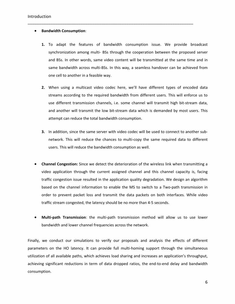
• Bandwidth Consumption:
1. To adapt the features of bandwidth consumption issue. We provide broadcast
synchronization among multi- BSs through the cooperation between the proposed server
and BSs. In other words, same video content will be transmitted at the same time and in
same bandwidth across multi-BSs. In this way, a seamless handover can be achieved from
one cell to another in a feasible way.
2. When using a multicast video codec here, we’ll have different types of encoded data
streams according to the required bandwidth from different users. This will enforce us to
use different transmission channels, i.e. some channel will transmit high bit-stream data,
and another will transmit the low bit-stream data which is demanded by most users. This
attempt can reduce the total bandwidth consumption.
3. In addition, since the same server with video codec will be used to connect to another sub-
network. This will reduce the chances to multi-copy the same required data to different
users. This will reduce the bandwidth consumption as well.
• Channel Congestion: Since we detect the deterioration of the wireless link when transmitting a
video application through the current assigned channel and this channel capacity is, facing
traffic congestion issue resulted in the application quality degradation. We design an algorithm
based on the channel information to enable the MS to switch to a Two-path transmission in
order to prevent packet loss and transmit the data packets on both interfaces. While video
traffic stream congested, the latency should be no more than 4-5 seconds.
• Multi-path Transmission: the multi-path transmission method will allow us to use lower
bandwidth and lower channel frequencies across the network.
Finally, we conduct our simulations to verify our proposals and analysis the effects of different
parameters on the HO latency. It can provide full multi-homing support through the simultaneous
utilization of all available paths, which achieves load sharing and increases an application’s throughput,
achieving significant reductions in term of data dropped ratios, the end-to-end delay and bandwidth
consumption.

Introduction ________________________________________________________________________
7
1.4 Organization of Thesis
Chapter 1: This chapter provides a review of literature relevant to this research topic.
Practically, a brief description of developed techniques for traffic alternation in WLAN, WiMAX. Further,
more research challenges and contributions are mentioned.
Chapter 2: Provides a theoretical background and an overview of the history and definition of WLAN,
WiMAX. Also, scenarios and current application are detailed in this chapter. In addition, details
presented for some of the WLAN multi-homing protocols, with their functional mechanisms also
described. Finally, the weakness for the current protocol will be shown, and how the ISP solves the
problems that appear in current multi-homing protocols.
Chapter 3: provides an overview of the most related work in the handover and cross layer issues with
respect to our proposed schemes.
Chapter 4: Discuss the novel proposed ISP protocol in details and discusses the performance metrics
used to evaluate the protocol. The operation for the ISP is explained and interface selection process is
discussed and introduced in detail. Also, presented are the novel functions for Probe Message between
source node and destination node to find an optimum path.
Chapter 5: In this chapter, the simulation software called OPNET is introduced and presented in depth.
Consequently, the ISP protocol implemented on OPNET v.14 is explained. Consequently, the design of
ISP architecture will be described in depth in the chapter, and the ISP wireless node design is presented
with relevant attributes for the nodes. Also, how the network settings for the source/destination nodes
and data packets operation will be presented in details with some experiment results.
Chapter 6: This chapter contains a detailed explanation of the different scenarios used for the well-
known multi-homing protocols such as MIPv6 and Shim6 in different environments. A complete
simulation result and analysis/discussion is presented with relevant graphs and tables. Furthermore, an
inclusive comparison is made with ISP protocol to determine optimal protocol performance.

Introduction ________________________________________________________________________
8
Chapter 7: Discusses the proposed schemes in WiMAX in detail and discusses the performance metrics
used to evaluate the protocol. The operation for the schemes is explained and interface selection
process is discussed and introduced in detail. Also, presented is the scalable coding scheme in the
wireless channels between source node and destination node to solve the traffic congestion issue.
Chapter 8: In this chapter, the WiMAX proposal implemented on OPNET v.14 is explained. In the first
part of the chapter, WiMAX node design is presented with relevant attributes for the nodes. Also, how
the network settings for the transmitter nodes and data packets operation will be presented in details
with some experiment results.
The chapter’s second part, a complete simulation result and analysis/discussion is presented with
relevant graphs and tables. Furthermore, an inclusive comparison is made to determine optimal
performance.
Chapter 9: Concludes the thesis and gives suggestion and discussions for future works.
1.5 References
[1] M. Gast, “802.11 Wireless Networks the Definitive Guide”, O'Reilly; Second Edition2005,
ISBN: 0596100523.
[2] B. H. Walke, S Mangold, L. Berlemann, “IEEE 802 Wireless Systems”, J. Wiley & Sons Ltd,
ISBN-13-978-0-470-01439-4, 2006.
[3] D.Thaler, “A Comparison of Mobility-Related Protocols,” IETF Draft, draft-thaler-mobility-
comparison-01.txt (work in progress), June, 2006.
[4] Kamran Etemad, “Overview of mobile WiMAX technology and evolution”, IEEE
Communications Magazine, Oct 2008.
[5] IEEE STD 802.16e, “IEEE Standard for Local and Metropolitan Area Networks”, Part 16: Air
Interface for Fixed Broadband Wireless Access Systems, Amendment 2: Physical and
Medium Access Control Layers for Combined Fixed and Mobile Operation in Licensed Bands,
Corrigendum 1, 2005.
[6] OPNET Modeler, OPNET Technologies Incorporation. www.opnet.com

Chapter 2: Introduction to IEEE 802.11 & IEEE 802.16 ________________________________________________________________________
2
Chapter 2
9
Introduction to IEEE 802.11 and IEEE 802.16 This chapter will navigate through the recent developments in wireless networks and give a
detailed overview of the many different aspects of IEEE 802.11 and IEEE 802.16 standards, such
as, classification, special features and mobility techniques.
2.1 Introduction
The wireless network communication and data transmission industry has seen exponential
growth in last few years. The advancement in the growing availability of wireless networks and
the emergence of portable devices, handheld computer, PDAs and Cell phones is now playing a
very important role in our daily routines. Surfing internet from railway station, airport, coffee
shops, public spaces, internet browsing on cell phones, and information or file exchange
between devices without wired connectivity are just few examples. All this ease is the result of
mobility of wireless devices while being connected to point to access the internet or information
from fixed or mobile infrastructure with ability to self-organising network (called wireless
networks). Typical example of wireless networks is office wireless local area networks (WLANs)
where wireless access point serves all wireless devices within the radius. Example of IEEE 802.11
standards [1] can be described as a group of nodes within a specific zone, wirelessly connected
to each other with the help of limited battery powered devices, well interfacing and efficient
routing protocol that helps them to maintain quality of communication, while they are changing
their position rapidly. Therefore routing in wireless networks plays an import role for data
forwarding, where each mobile node (MNs) can continuously access the Internet from any
location, any time. A mobile node can change its point of attachment from one link to another,
while still being reachable via its home address.
Chapter 2: Introduction to IEEE 802.11 & IEEE 802.16 ________________________________________________________________________
10
2.2 IEEE 802.11 (WLAN) Network
Wireless networks can be broadly categorized into two categories: infrastructure based wireless
networks and infrastructure less wireless networks (Ad hoc wireless networks). The IEEE 802.11
is the Infrastructure based wireless networks that rely on an Access point which is a device that
acts as a bridge between the wired and wireless networks. With the help of such an access
point, wireless nodes can be connected to the existing wired or wireless networks.
WLANs based on the IEEE 802.11 (a/b/g, Wi-Fi technology) specification family [2] have gained
popularity as being low-cost solutions that are easy to install and provide broadband
connectivity, and such networks are being widely deployed in private spaces (e.g. homes and
workplaces and as hot spots in public spaces, waiting areas and hotel lobbies). A large number
of competing organizations or Internet service providers currently provide internet access
independently. In wireless network communication, nodes communicate with others using
wireless channels. Two important issues are used in the wireless networks the spectrum
frequency ranges and different data rates. For example IEEE 802.11a/g [2] used 54Mbit/sec,
IEEE 802.11b [2] used 11Mbit/sec. The signal strength in a wireless medium decreased when the
signal travels further beyond a certain distance, the strength reduced to the point where
reception is not possible. There are several medium access (MAC) are used in wireless networks
to control the use of the wireless medium. There are Bluetooth MAC layer 802.15 [3] and WLAN
MAC layer 802.11 [4]. The topology of the wireless network can be different with time because
of the mobility feature. For example in wireless networks, the host or the subnet may be move
from one place to another. Traditional networks require re-configuration of IP address used by
these host or subnet at the new place. A network enable with mobile IP [5] allows these hosts or
subnet to move without any manual address re-configuration. The hosts can be remaining
moving around.
2.3 IEEE 802.11 (WLAN) Connectivity
The IEEE 802.11 network is based on a cellular architecture where the systems is subdivided into
cells, where each cell (Known as Basic Service Set or BSS) is controlled by a Base Station (Known
as Access Point or AP). BSSs are interconnected by a system known as Distribution System or DS,
where the APs are interconnected either by wired or wireless mode [6]. A set of one or more

Chapter 2: Introduction to IEEE 802.11 & IEEE 802.16 ________________________________________________________________________
11
Basic Service Sets interconnected by a DS is known as Extended Service Set or ESS. Wireless LAN
station or (STA) is any device that contains the functionality of the 802.11 protocol; Medium
Access Control (MAC), physical layer (PHY), and a connection to the wireless media. Typically,
the 802.11 functions are implemented in the hardware and software of a network interface card
(NIC). A station could be a laptop PC, handheld device, or an Access Point (AP). All stations
support the 802.11 station services of authentication, de- authentication, privacy, and data
delivery [7].
Figure 2-1: IEEE 802.11 network connectivity [7]
Wireless nodes or devices should be able to detect presence of other such devices to allow
communication and information sharing. Besides that, it should also be able to identify types of
services and corresponding attributes. Since the number of wireless nodes change and as a
result, the routing information also changes to reflect changes in link connectivity. Hence, the
topology of the network is much more dynamic and the changes are often unpredictable as
compared to the fixed nature of existing wired networks.
The dynamic nature of wireless medium, fast and unpredictable topological changes, link failure,
quality degradation and mobility raise many challenges for designing an efficient protocol for
quality degradation detection. Due to the immense level of challenge in designing protocols for
wireless networks, there are a number of recent developments, all focussing on provision of an
optimum solution for mobility routing. However, a majority of these solutions attain a specific

Chapter 2: Introduction to IEEE 802.11 & IEEE 802.16 ________________________________________________________________________
12
goal (for example minimizing delay, overhead etc) while compromising other factors (for
example scalability, route reliability etc). Thus, an optimum routing protocol that can cover most
of applications/user requirements and at the same time cope up with the stringent behaviour of
wireless medium is ever desirable.
Each of the nodes has one or more wireless interface and communicates with each other over
either radio or infrared. Laptop computers and PDAs that communicate directly with each other
are some examples of nodes in wireless network. Wireless network nodes are often mobile, but
can also consist of stationary nodes, such as access points to the Internet.
The network connectivity comprises of APs periodically broadcast beacon frames to announce
their presence to the stations. To discover working APs on one channel, the wireless station
should switch to that channel and waits for the beacon frames from APs within the coverage.
The default beacon-generating interval is 100ms. It takes 100ms × 11 to 1 second to discover all
APs working in the standard eleven channels.
Attributing to mobility, the signal strength and the signal-to-noise ratio of the signal from a
station’s current AP might degrade and cause it to lose connectivity and to initiate a handover.
At this point, the node might not be able to communicate with its current AP. Thus, the node
needs to find the potential APs (in range) to associate to.
This was accomplished by a MAC layer function [8], [9]; scan. During a scan, the card listens for
beacon messages (sent out periodically by APs at a rate of 10 ms), on an assigned channel. Thus,
the station can create a list of APs prioritized by the received signal strength.
2.4 Classification according to the coverage area
As shown in Figure 2-7 , it can classify wireless networks, depending on their coverage area, into
several classes: Personal Area Network (PAN), Local (LAN), Metropolitan Area Network (MAN)
and Wide Area Network (WAN) area networks Wide and Metropolitan area networks that are
mobile multi-hop wireless networks presenting many challenges that are still being solved (e.g.,

Chapter 2: Introduction to IEEE 802.11 & IEEE 802.16 ________________________________________________________________________
13
addressing, routing, location management, security, etc.) and their availability is not on
immediate horizon.
A PAN communicating range is typically up to 10 meters. Wireless PAN (WPAN) technologies in
the 2.4-10.6 GHz band are the most promising technologies for widespread PAN deployment.
Spread spectrum is typically employed to reduce interference and utilize the bandwidth
[10],[11].
In the last few years, the use of Wireless technologies in the LAN environment has become more
and more important, and it is easy to foresee that the wireless LAN (WLAN). WLAN used in
different environment such as home, office, and at the road in public location. WLAN also called
Wireless Fidelity (Wi-Fi), is based on the 802.11 standard its freedom to internet users also they
offer greater flexibility then wired LAN. Most of the pc’s, laptops, phones, and PDA’s are capable
to connect to the internet via WLAN. A WLAN has a communication range typical of a single
building or a cluster of buildings, i.e., 100-500 meters. Bluetooth technology based on IEEE
802.15 provides a way to connect and exchange information between devices such as mobile
phones, laptops, GPS receivers through a secure, globally unlicensed Industrial. it’s typical range
within an area of maximum 30 meters, with 2.4 GHz short range radio frequency bandwidth.
Where WLAN usually provide indoor and outdoor for wireless signal smaller, the wireless
technology are already present new technology that provide larger coverage area than WLAN,
the technology called Worldwide Interoperability for Microwave Access (WiMAX) technology.
WiMAX based on 802.16 IEEE standard also and defined as a wireless metropolitan area
network (MAN) technology that will provide a wireless alternative to wire and digital subscriber
line (DSL) for last mile broadband access. WIMAX has communication range up to 50 km, also
allow the users to get broadband connections without the directly connected with base station,
and provide shared data rates of up to 70Mbps, which is enough bandwidth to support more
than 60 T1 link and hundreds of home and office DSL connections line. Likewise, WIMAX full
from quality of service (QoS) support. Finally, the latest wireless technologies but not least
called mobile broadband wireless access (MBWA) which is approved by IEEE standard board and
defined as 802.20. The MBWA are similar to the IEEE 802.16ein that they use OFDMA, also
provide very high mobility and the shared data rate up to 100Mbps.at this time no operator has
committed to the MBWA technology. The others are IEEE 802.21 supports algorithms enabling

Chapter 2: Introduction to IEEE 802.11 & IEEE 802.16 ________________________________________________________________________
14
seamless handover between networks of the same type as well as handover between different
network types also called Media Independent Handover (MIH) or vertical handover. IEEE 802.22
(WRAN) Wireless Regional Area Network, aims at using cognitive radio techniques to allow
sharing of geographically unused spectrum allocated to the Television Broadcast Service, on a
non-interfering basis, to bring broadband access to hard-to-reach, low population density areas,
typical of rural environments, and is therefore timely and has the potential for a wide
applicability worldwide.
Figure2-2: WLAN networks taxonomy according to coverage area
There are currently four (major) specifications in the WLAN family 802.11, 802.11a, 802.11b,
and 802.11g. All four use the Ethernet protocol and CSMA/CA (Carrier Sense Multiple Access
with Collision Avoidance) for path sharing. There are also other members (802.11c, 802.11d,
802.11e, 802.11f, 802.11n, etc) in this family, but these four are of greater interest here. The
WLAN in terms of the mobility is the other metric used to classify it. Table 1 shows the
comparison of various Wireless communication technologies.

Chapter 2: Introduction to IEEE 802.11 & IEEE 802.16 ________________________________________________________________________
15
Table 2-1: Comparison of Various Wireless Communication Technologies
2.4.1 Classification According to Mobility Support
Internet access is increasingly being employed by large enterprises and data centres to extract
good performance and reliability from their Internet Service Providers connections. Networks
today can employ a variety of route control products to optimize their Internet access
performance and reliability. Some end-networks have the ability of having single/different
connections to Internet, potentially through different Internet providers. Thus depending on
ISPs employment by end-networks, configuration, and communication, a WLAN can either be
single or multi-homed network.

Chapter 2: Introduction to IEEE 802.11 & IEEE 802.16 ________________________________________________________________________
16
2.4.1.1 Single Homed network
Nodes are in their reachable area and can communicate to Internet, potentially a single service
provider or a device with a single network interface. Thus, runs all its data and Internet access
traffic over a single network and choose the best access method based on the needs of the
location. The most common use of these networks is home networks, when most service
providers companies only allocate a single IP address to each residential customer.
2.4.1.2 Multi-Homed Network
Multi-homing is the network’s ability of having different connections to Internet, potentially
through different service providers. There is a proliferation that nodes can access Internet and
technologies everywhere. Therefore, it is increasingly common to have devices with several
network interfaces so the mobile nodes can potentially roam between different types of access
network (3G, WLAN, Ethernet, and Bluetooth). To gain full advantage of robustness in
communications and ubiquitous access by the ability of using the different accesses where they
are available, a multi-homing solution at the host level is required.
Multi-homed network has many advantages, such as bandwidth enhancement, load sharing, bi-
casting or duplicating a flow simultaneously among many routes, etc. Users can have a
preference of network settings for different applications when being able to simultaneously
access multiple access networks. However, the main benefit of multi-homing is that it provides
resiliency against network path failures.

Chapter 2: Introduction to IEEE 802.11 & IEEE 802.16 ________________________________________________________________________
17
2.5 Multi-Homed Network Characteristics
Multi-homing has the following features that are necessary to be considered while suggesting or
designing solutions for this type of networks.
§ Multi-homing is increasingly being employed by large enterprises and data centres to
extract good performance and reliability from their ISP connections.
§ A multi-homed mobile node (MN) is either a single mobile host or a mobile router,
together with a completely mobile network, that is equipped with multiple network
interfaces.
§ In this context, it is desired and practical that both a mobile user and the network can
strategically trigger a handover to switch all or the selected application flows from one
interface or access network to another. it refer to such an operation as a flow handover.
§ Multi-homing route control does not require any modification to the existing Internet
routing protocols, and relies solely on end-network decisions. Thus will imply that good
performance can still be extracted from the network by making clever use of available
Internet routes.
§ Multi-homing has been increasingly implied for improving network performance,
reducing bandwidth costs, and optimizing the way in which network links are used.
§ The drawbacks of the current multi-homed network; during handover between
networks, there is no perfect method to allocate the connecting interface. Moreover, do
not look at the chosen interface’s liability. There is a High possibility of data loss during
interfaces switching. There is a need for a load balance and an adaptive design
according to the type of application.
Chapter 2: Introduction to IEEE 802.11 & IEEE 802.16 ________________________________________________________________________
18
2.6 Worldwide Interoperability for Microwave Access (WiMAX)
The increasing demand for high speed mobile broadband access to multimedia and Internet
applications and services over the last few years has created new interest among existing and
emerging operators to explore new technologies and network architectures to offer such
services at low cost to operators and end users. Motivated by the success of Wi-Fi and
considering the need for such a paradigm shift, many vendors and operators joined IEEE forum
to develop a new end-to-end solution to address the new demands and opportunities.
The IEEE 802.16 Working Group is the IEEE group for wireless metropolitan area network. The
IEEE 802.16 standard defines the Wireless MAN (metropolitan area network) air interface
specification (officially known as the IEEE Wireless MAN standard) [12].
WiMAX is a standard-based wireless technology that provides high throughput broadband
connections over long distance. WiMAX can be used for a number of applications, including “last
mile” broadband connections, hotspots and high-speed connectivity for business customers. It
provides wireless metropolitan area network (MAN) connectivity at speeds up to 70 Mbps and
the WiMAX base station (BS) can offer greater wireless coverage of 5 to 10 km with targeting
two different frequency regions between 10-66 GHz and below 2-11 GHz. Thus enabling
broadband access directly to WiMAX-enabled portable devices ranging from smart phones and
PDAs to notebook and laptop computers.
WiMAX standard is based on an radio frequency (RF) technology called Orthogonal Frequency
Division Multiplexing (OFDM), which is a mean of transferring data with carriers of width of
5MHz or greater are used. Below 5MHz carrier width, current Code Division Multiple Access
(CDMA) based 3G systems are comparable to OFDM in terms of performance [13].
While the initial versions of 802.16/a/d focused on fixed applications, the latest versions of
802.16e amendment were formed in 2005 [14], which have included many new features and
functionalities needed to support enhanced Quality of Service (QoS) and mobility issues. An
overview of different WiMAX standards specifications are shown in the table 2-2.

Chapter 2: Introduction to IEEE 802.11 & IEEE 802.16 ________________________________________________________________________
19
Table 2-2: Comparison of Various WiMAX Standards
2.6.1 Mobile WiMAX Mobile WiMAX, Based on the IEEE 802.16e-2005 Air Interface that added mobility features and
attributes to the standard [15]. Mobile WiMAX enables cell phone-like applications on a much
larger scale. For example, mobile WiMAX enables streaming video to be broadcast from a
speeding police or other emergency vehicle at over 70 MPH. It potentially replaces cell phones
and mobile data offerings from cell phone operators. In addition, it improved security issues

Chapter 2: Introduction to IEEE 802.11 & IEEE 802.16 ________________________________________________________________________
20
over fixed WiMAX. Mobile WiMAX will be very valuable for emerging services such as mobile TV
and gaming.
Figure 2-3: Mobile WiMAX [16]
The mobile WiMAX features enable mobile systems to be configured based on a common base
feature set thus ensuring baseline functionality for terminals and base stations that are fully
interoperable. Its systems offer scalability in both radio access technology and network
architecture, thus providing a great deal of flexibility in network deployment options and
service.
2.7 Mobile WiMAX Features
1. Mobility: Mobile WiMAX supports optimized handover schemes with latencies less
than 50 milliseconds to ensure real-time applications such as VoIP perform without
service degradation. Flexible key management schemes assure that security is
maintained during handover.
2. High Data Rates: The use of MIMO (Multiple Input Multiple Output) antenna
techniques along with flexible sub-channelization schemes, Advanced Coding and

Chapter 2: Introduction to IEEE 802.11 & IEEE 802.16 ________________________________________________________________________
21
Modulation all enable the mobile WiMAX technology to support data rates up to 63
Mbps per sector for the downlink (DL) streams and data rates up to 28 Mbps per
sector for the uplink (UL) streams in a 10 MHz channel.
3. Scalability: Mobile WiMAX technology is performed to be able to scale to work in
different channelization from 1.25 to 20 MHz to comply with varied worldwide
requirements. This also allows many economies to realize the benefits of the mobile
WiMAX for their specific geographic needs such as providing affordable internet
access in rural settings versus enhancing the capacity of mobile broadband access in
metro and suburban areas.
4. Efficient Spectrum: Flexible spectrum allocation in that it is scaled to work in different
channelization from 1.25 to 20 MHz complying with diverse requirement in different
countries.
5. Security: Enhanced security in that new authentication was added. It added support
for a diverse set of user credentials exists including; SIM/USIM cards, Smart Cards,
Digital Certificates, and Username/Password schemes.
2.8 Quality of Service (QoS) Support
Quality of Service is an essential feature of the standard, as multiple types of traffic may be
carried through the network. Quality of service is strongly achieved by using a connection-
oriented MAC architecture and PHY components, where all downlink and uplink connections are
controlled by the serving BS. Therefore, mobile WiMAX standard provides Quality of Service by
using the following techniques that will be essential to the proposals in later chapters, reside at
both physical and MAC layer [17]:
At Physical Layer
1. Frequency division duplex (FDD)
2. Time division duplex (TDD)
3. Forward Error Correction (FEC)

Chapter 2: Introduction to IEEE 802.11 & IEEE 802.16 ________________________________________________________________________
22
4. Orthogonal frequency-division multiplexing (OFDM)
5. Orthogonal Frequency Division Multiple Access (OFDMA)
6. Video coding technique.
At MAC Layer
MAC supports several service classes in WiMAX for prioritizing traffic.
1. Unsolicited Grant Service (UGS): Supports Real Time data streams, having fixed size
packets issued at regular intervals e.g. VoIP.
2. Real time Polling Service (rtPS): Supports Real Time data streams, having variable size
packets issued at regular intervals e.g. streaming audio or video.
3. Non-real time Polling Service (nrtPS): Supports delay tolerant data with variable packet
sizes, for which a minimum data rate is specified e.g. ftp.
4. Best Effort (BE): Supports data streams where no minimum service is required and
packets are handled on a space-available basis that is less sensitive to latency than the
other classes e.g. data transfer and web browsing.
5. Extended real time Polling Service (ertPS): Supports Real Time data streams, with
variable data rate e.g. VoIP (voice with activity detection) over the WiMAX network.
2.8.1 Physical Layer The WiMAX system relies on a new radio physical (PHY) layer and appropriate Media Access
Controller (MAC) layer to support all demands driven by the user applications. Since WiMAX is
able to provide a reliable service over long distance to customers using indoor terminals or PC
cards (like today's WLAN cards). Where in past, these applications were limited to the transmit
power to comply with the requirements, that limited the link budget. Therefore, adding new
attributes to sub-channelling in uplink and smart antennas at the base station has to overcome
these constraints.

Chapter 2: Introduction to IEEE 802.11 & IEEE 802.16 ________________________________________________________________________
23
The PHY layer modulation is based on orthogonal frequency division multiple access (OFDMA)
which is more suitable for non-LOS operation due to the simplicity of the equalization process
for multicarrier signals and when it comes to handling the significant delay spread caused by the
typical NLOS reflections. In addition, PHY deploys Forward Error Correction (FEC) technique to
allow the receiver to correct some errors without having to request a retransmission of data.
This can be used in conjunction with centralized MAC layer to provide a reliable end-to-end link
with optimized support of QoS for different types of services (VoIP, real-time and non real-time
services, best effort), as will be discussed in later section. WiMAX PHY provides flexibility in
terms of channelization, carrier frequency, and duplex mode (TDD and FDD) to meet a variety of
requirements for available spectrum resources and targeted services.
2.8.1.1 OFDMA Basics The mobile WiMAX provides high performance due to relying upon the upgraded PHY layer
Orthogonal Frequency Division Multiplexing Access (OFDMA) [18] which, is multiplexing
technique, supports multipath in the non-line-of-sight (NLoS) environments. Whereby different
users can be allocated different subsets of the OFDM tones resulting in the ability to generate
higher throughput and improved network coverage.
The channel subcarriers are divided into several groups of subcarriers called subchannels.
Mobile WiMAX based on OFDMA-PHY, however, allows subchannelization in both the uplink and
the downlink, not like in Fixed WiMAX allows a limited form of sub-channelization in the uplink
only. The subchannels form the minimum frequency resource-unit is allocated by the base
station. Therefore, different subchannels may be allocated to different users as a multiple-
access mechanism. This type of multi-access scheme is called Orthogonal Frequency Division
Multiple Access (OFDMA). As WiMAX Forum specifies the 256-carrier OFDM. For this reason, the
rest of the article will focus primarily on the 256-carrier OFDM air interface. Of these 256
subcarriers, 192 are used for user data, with 56 for a guard band and eight used as permanent
pilot symbols. The standard defines 16 subchannels, where 1, 2, 4, 8, or all sets can be assigned
to a subscriber station (SS) in the uplink. OFDM takes a block of serial symbols and transmits
them in parallel using carriers, which are mathematically orthogonal.

Chapter 2: Introduction to IEEE 802.11 & IEEE 802.16 ________________________________________________________________________
24
Say there is N symbols to be transmitted serially, with period Tn. If we take those N symbols and
transmit them on N parallel orthogonal carriers, each with period T, this in effect reduce the
symbol rate on each sub-carrier, as we have T = NTn. This reduction in symbol rate means that
the effect of delay spread is reduced, and so there is no need for equalization at the receiver.
OFDMA works by assigning a certain subset of the sub-carriers to each client to provide
multiple-access.
Finally, OFDMA is able to provide a high spectral efficiency of about 3 - 4 bit/s/Hz. As in contrast
to single carrier modulation, the OFDMA signal has an increased average ratio and increased
frequency accuracy requirements. Thus, the selection of appropriate power amplifiers and
frequency recovery concepts are crucial.
2.8.1.2 TDD Frame Structure The WiMAX PHY layer supports different configurations, such Time Division Duplex (TDD) and
Frequency Division Duplex (FDD). In this article we will consider the TDD structure [19].
TDD divides the data stream into frames that use different time slots assigned to each UL and DL
streams. Therefore enable both streams to share the same frequency medium. Unlike the FDD
where the uplink and downlink sub-bands are said to be separated by the frequency offset. Time
division duplex has a strong advantage in the case where the asymmetry of the uplink and
downlink data speed is variable. And Frequency division duplex is only efficient in the case of
symmetric traffic.
The frame structure as shown in figure 2-20, contains the downlink (DL) subframe and uplink
(UL) subframe.
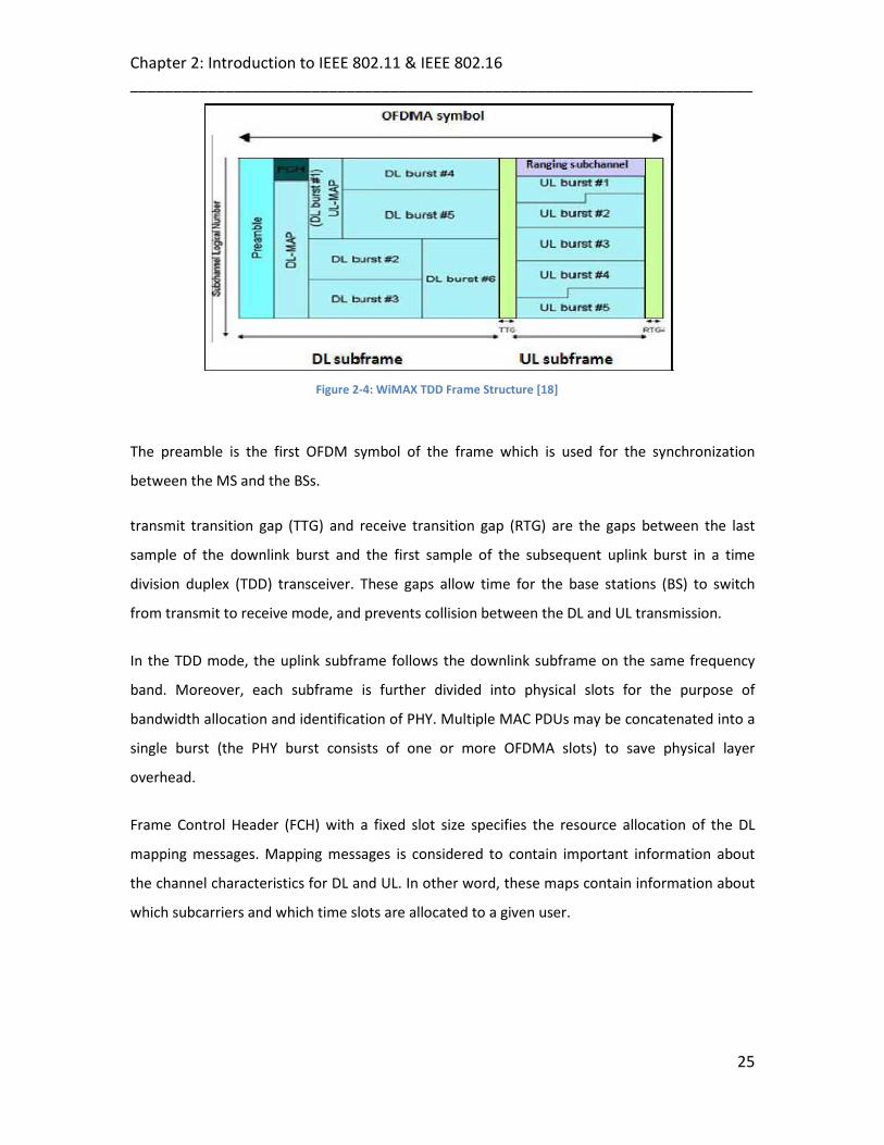
Chapter 2: Introduction to IEEE 802.11 & IEEE 802.16 ________________________________________________________________________
25
Figure 2-4: WiMAX TDD Frame Structure [18]
The preamble is the first OFDM symbol of the frame which is used for the synchronization
between the MS and the BSs.
transmit transition gap (TTG) and receive transition gap (RTG) are the gaps between the last
sample of the downlink burst and the first sample of the subsequent uplink burst in a time
division duplex (TDD) transceiver. These gaps allow time for the base stations (BS) to switch
from transmit to receive mode, and prevents collision between the DL and UL transmission.
In the TDD mode, the uplink subframe follows the downlink subframe on the same frequency
band. Moreover, each subframe is further divided into physical slots for the purpose of
bandwidth allocation and identification of PHY. Multiple MAC PDUs may be concatenated into a
single burst (the PHY burst consists of one or more OFDMA slots) to save physical layer
overhead.
Frame Control Header (FCH) with a fixed slot size specifies the resource allocation of the DL
mapping messages. Mapping messages is considered to contain important information about
the channel characteristics for DL and UL. In other word, these maps contain information about
which subcarriers and which time slots are allocated to a given user.

Chapter 2: Introduction to IEEE 802.11 & IEEE 802.16 ________________________________________________________________________
26
2.8.1.3 Video Coding Technique
Video transmission over the Internet has obtained popularity during the recent years, which is
mainly the result of the introduction of video conferencing and video-telephony applications.
These have made it very common to bring many applications to the public, such as transmitting
video over the Internet and over telephone lines, telemedicine (medical consultation and
diagnosis from a far distance), education fields, and other computer based purposes.
However, the current structure of the Internet is unable to guarantee any specific bandwidth for
a connection. Many video coding standards have tried to deal with this problem by introducing
the scalability feature as adapting video streams to the channel variant conditions and the
available bandwidths. In this thesis, we focus on the main technical features of most common
scalable video coding technique, Known as Scalable Video Coding (SVC).
2.8.1.3.1 Scalable Video Coding (SVC)
With the increase in the Internet access bandwidth, more applications has gained popularity
during the recent years and started to use the streaming audio and video contents, which is
mainly the result of the introduction of videoconferencing and video-telephony applications.
The Scalable Video Coding (SVC) is the extension of H.264/AVC which is the based codec
standard developed under the ITU-T VCEG together with the Moving Picture Experts Group
(MPEG) [20]. It has added significant improvements in video compression capability. SVC was
designed to support bandwidth efficient and loss resilient video streaming bitstreams.
Its technology encodes the video at the highest resolution and allows the data bit-stream to be
adapted to provide various lower resolutions streams, results in several types of encoded data
streams with a consideration to their bandwidth requirement. The SVC extension was
completed in November 2007.
The coding aim for streaming video is to optimize the video quality for a wide range of bit rates.
In the streaming video applications, the codec servers normally have to serve a large amount of
users, specifically when the user’s application resolution is too small and when the bandwidth
between some users and the server is too narrow to support higher resolution sequences.

Chapter 2: Introduction to IEEE 802.11 & IEEE 802.16 ________________________________________________________________________
27
Therefore, the term scalability in this article refers to the removal of redundant parts of the
video bit stream in order to adapt it to the various needs of varying terminal users capabilities
and network conditions as well, where the video quality degradation is smooth when users
move within and across cells. The scalable coding is needed to provide better resolutions.
The following figure, gives example of real-time application to show how the codec works.
Figure 2-5: SVC Encode/Decode. (CIF: lowest definition, lowest resolution), (SD: Standard Definition, medium resolution) and (HD: High Definition, highest resolution) [21].
The channel bandwidth is time varying due to the mobility and the available resources; besides,
different users are located at different location in the network that results to different
bandwidth consumptions throughout the transmission medium. However, the adaptation of a
single stream can be achieved through the transcoding techniques, which are currently used in
multipoint control units in video conferencing systems. It uses layered structure to provide
spatial, temporal, and quality (SNR, signal to noise ratio) scalability simultaneously. According to
the network conditions and receiver capabilities, a streaming server to provide various spatial,
temporal, and quality (SNR) resolutions levels can easily adapt the pre-encoded SVC bitstream.
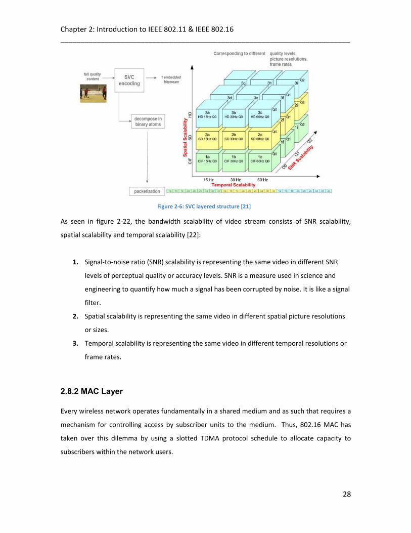
Chapter 2: Introduction to IEEE 802.11 & IEEE 802.16 ________________________________________________________________________
28
Figure 2-6: SVC layered structure [21]
As seen in figure 2-22, the bandwidth scalability of video stream consists of SNR scalability,
spatial scalability and temporal scalability [22]:
1. Signal-to-noise ratio (SNR) scalability is representing the same video in different SNR
levels of perceptual quality or accuracy levels. SNR is a measure used in science and
engineering to quantify how much a signal has been corrupted by noise. It is like a signal
filter.
2. Spatial scalability is representing the same video in different spatial picture resolutions
or sizes.
3. Temporal scalability is representing the same video in different temporal resolutions or
frame rates.
2.8.2 MAC Layer Every wireless network operates fundamentally in a shared medium and as such that requires a
mechanism for controlling access by subscriber units to the medium. Thus, 802.16 MAC has
taken over this dilemma by using a slotted TDMA protocol schedule to allocate capacity to
subscribers within the network users.
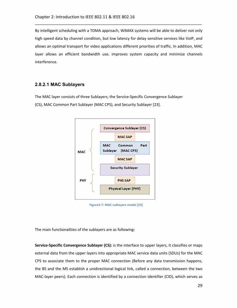
Chapter 2: Introduction to IEEE 802.11 & IEEE 802.16 ________________________________________________________________________
29
By intelligent scheduling with a TDMA approach, WiMAX systems will be able to deliver not only
high speed data by channel condition, but low latency for delay sensitive services like VoIP, and
allows an optimal transport for video applications different priorities of traffic. In addition, MAC
layer allows an efficient bandwidth use, improves system capacity and minimize channels
interference.
2.8.2.1 MAC Sublayers The MAC layer consists of three Sublayers; the Service-Specific Convergence Sublayer
(CS), MAC Common Part Sublayer (MAC CPS), and Security Sublayer [23].
Figure2-7: MAC sublayers model [23]
The main functionalities of the sublayers are as following:
Service-Specific Convergence Sublayer (CS): is the interface to upper layers, it classifies or maps
external data from the upper layers into appropriate MAC service data units (SDUs) for the MAC
CPS to associate them to the proper MAC connection (Before any data transmission happens,
the BS and the MS establish a unidirectional logical link, called a connection, between the two
MAC-layer peers). Each connection is identified by a connection identifier (CID), which serves as

Chapter 2: Introduction to IEEE 802.11 & IEEE 802.16 ________________________________________________________________________
30
a temporary address for data transmissions over the particular link and its associated with
certain level of QoS. An SDU is the basic data unit exchanged between two adjacent protocol
layers.
The CS processes higher layer SDUs to suppress unused higher layer information. After
classification, the SDU is delivered to the corresponding Service Access Point MAC CPS (SAP) that
includes information to process the SDUs. At the receiving side, the suppressed header is
reconstructed before it is handed over to the higher layer protocol via the SAP. As shown in
figure 2-24.
Figure 2-8: Service-Specific Convergence Sublayer (CS) [23]
MAC Common Part Sublayer (MAC CPS): the next sublayer, which provides the essential
functionality for system and channel access, allocation of bandwidth, and connection
establishment and maintenance. This sublayer also handles the QoS applications aspect of data
transmission.
It receives the data already classified to particular CIDs; the QoS is applied to the transmission
and scheduling of the data over the PHY layer.

Chapter 2: Introduction to IEEE 802.11 & IEEE 802.16 ________________________________________________________________________
31
Security Sublayer: resides below the CPS, it provides functionalities such as authentication,
secure key exchange, and encryption functions.
2.9 Mobility Support
IEEE 802.16e-2005 forms the basis for the WiMAX solution for nomadic and mobile applications
and is often referred to Mobile WiMAX. This standard is able to support mobility up to vehicular
speeds of 70–80 mile/hour with a data rate up to 2Mbps. Within an asymmetrical link structure
that will enable the subscriber station to have a handheld form, factor e.g. PDAs, phones, or
laptops.
There are two critical issues for mobile applications; Battery life (power) and handover. Mobile
WiMAX supports Sleep Mode and Idle Mode to enable power-efficient MS operation. Mobile
WiMAX also supports seamless handover to enable the MS to switch from one base station to
another at vehicular speeds without interrupting the connection. In this thesis, we focus on the
Handover issue.
2.9.1 Handover in WiMAX
IEEE 802.16 Handover procedures concluded in a mobile device’s ability to switch the
connection from its current serving base station to another with better signal quality, from one
IEEE 802.16 network type to another (such as from 802.11b to 802.16), and even from wired to
802.11 or 802.16 connections. The goal is to standardize the handover so devices are
interoperable as they move from one network area coverage to another Today, 802.11 users
can move around a building or a hotspot and stay connected, but if they leave, they lose their
connection. With 802.16, users will be able to stay connected. Furthermore, having a standard
in place opens the door to volume component suppliers that will allow equipment vendors to
focus on system design, and to develop the essential end-to-end solution. For example, when
having 802.16e capabilities either embedded in a PDA or laptop (or added through an 802.16e-
enabled card) users remain connected within an entire metropolitan area. A laptop could
connect via Ethernet or 802.11 when cooped, and stay connected with 802.16 when roaming
the city or suburban areas.

Chapter 2: Introduction to IEEE 802.11 & IEEE 802.16 ________________________________________________________________________
32
IEEE 802.16e standard supports three handover methods [24]:
1. Hard Handover (HHO),
2. Fast Base Station Switching (FBSS)
3. Macro Diversity Handover (MDHO).
The HHO is mandatory while FBSS and MDHO are two optional modes. Up till now, only HHO and FBSS
are adequately defined in the standard for practical use. However, both had the physical radio link
broken before it is re-established at the target access point that results in handshake latency. In this
article, when handover is mentioned, it refers to HHO. As in HHO, the Mobile Station (MS) is connected
only to one BS at any given time. If the MS to handover from the current serving BS, it selects only one
target BS from a subset of the recommended BSs and starts connecting to it before disconnecting from
the current serving BS.
The WiMAX Forum has developed several techniques for optimizing hard handover within the
framework of the 802.16e standard. These improvements have been developed with the goal of keeping
MAC layer handover delays to less than 50 milliseconds.
Although IEEE 802.16 MAC layer handover process has been studied in literature survey [25], but it is
important to discuss it briefly in the context with the proposed handover schemes components
discussed in later chapter, to show some clarity of how does the messages exchange and corresponding
proposed protocols work in the network.
1. Network Topology Advertisement
As shown in figure 2-27, The BSs periodically starts broadcasting Mobile Neighbour Advertisement
(MOB_NBR_ADV) control messages to the MS ( when its power on) that contain both physical layer (i.e.,
radio channel) and link layer (e.g., MAC address) information, in addition to Bandwidth and QoS.
By means of such broadcasts, the MS becomes aware of the neighboring BSs. The MS then triggers the
scan phase.

Chapter 2: Introduction to IEEE 802.11 & IEEE 802.16 ________________________________________________________________________
33
2. Scanning/Ranging Procedure
In the scan phase of HO, the MS scans and synchronizes with the neighboring BSs based on channel
information from the neighbour advertisement. In order to find an appropriate BS target, the serving BS
scans the available channels of the downlink (DL) frequency band. The MS is looking for a well-known DL
preamble frame. Since the preamble is transmitted periodically, the BS should gather the frame duration
and having synchronized it on time.
Because of receiving preamble frame, the channel estimation, initialization and equalization procedures
are taken place.
Figure 2-9: Scanning and ranging procedure
The MS regularly receives channel information about the neighboring BSs through the MOB_NBR-ADV
message from the current serving BS. If the signal strength weakens, The MS will send a Mobile Scanning
Request (MOB_SCN_REQ) message to the neighboring BS with a potential target BS list (selected in the
previous phase). The serving BS replies a Mobile Scanning Response (MOB_SCN_RSP) message to the MS
to allocate a scanning duration. The MS selects candidate target BSs based on the signal strength and
response time of each BS, acquired from scanning.
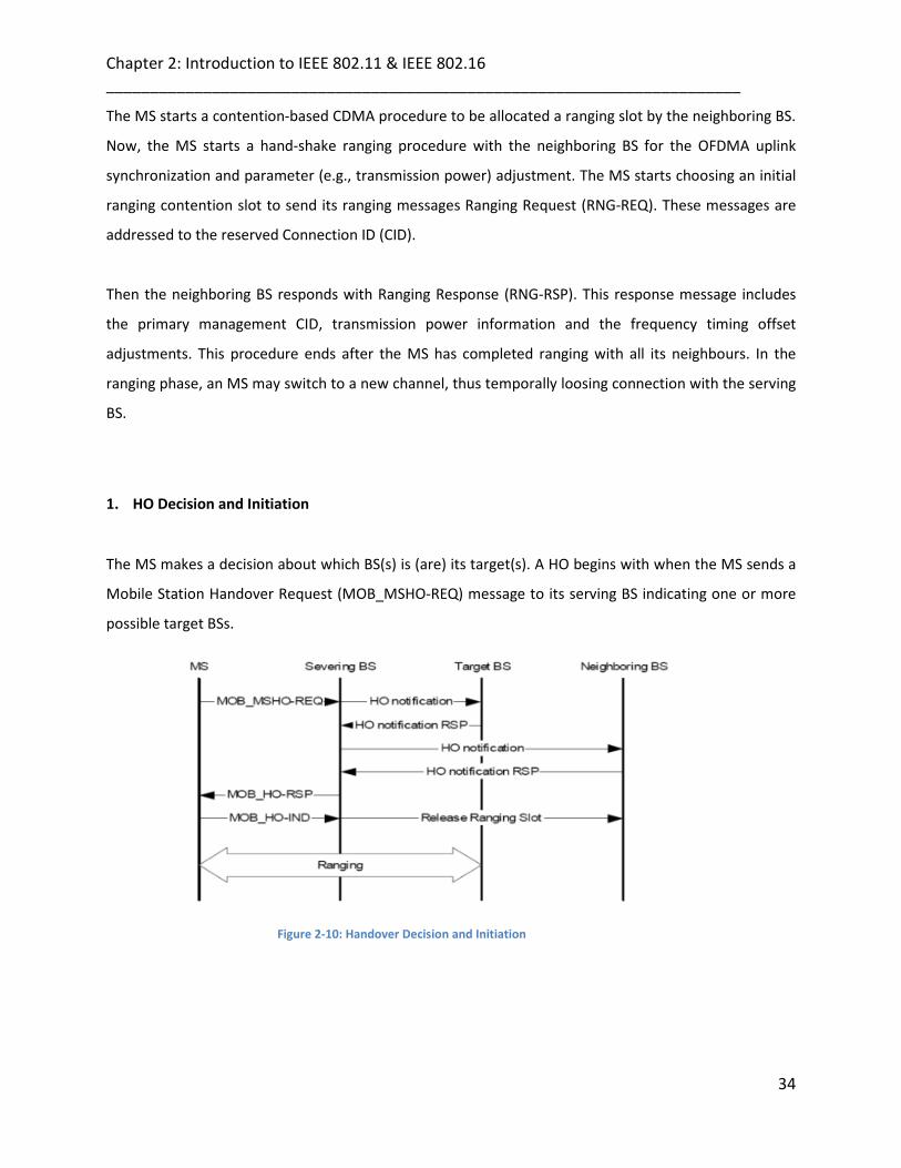
Chapter 2: Introduction to IEEE 802.11 & IEEE 802.16 ________________________________________________________________________
34
The MS starts a contention-based CDMA procedure to be allocated a ranging slot by the neighboring BS.
Now, the MS starts a hand-shake ranging procedure with the neighboring BS for the OFDMA uplink
synchronization and parameter (e.g., transmission power) adjustment. The MS starts choosing an initial
ranging contention slot to send its ranging messages Ranging Request (RNG-REQ). These messages are
addressed to the reserved Connection ID (CID).
Then the neighboring BS responds with Ranging Response (RNG-RSP). This response message includes
the primary management CID, transmission power information and the frequency timing offset
adjustments. This procedure ends after the MS has completed ranging with all its neighbours. In the
ranging phase, an MS may switch to a new channel, thus temporally loosing connection with the serving
BS.
1. HO Decision and Initiation
The MS makes a decision about which BS(s) is (are) its target(s). A HO begins with when the MS sends a
Mobile Station Handover Request (MOB_MSHO-REQ) message to its serving BS indicating one or more
possible target BSs.
Figure 2-10: Handover Decision and Initiation

Chapter 2: Introduction to IEEE 802.11 & IEEE 802.16 ________________________________________________________________________
35
After receiving a response from a target BS, the MS notifies the serving BS about its decision to perform
a HO by means of a HO Indication (MOB_HO IND) message. However, the possible ranging procedure
after does introduce additional latency.
2. Network Re-entry
After all the physical parameter adjustments have been completed successfully, the network re-entry
process is initiated to establish connectivity between the MS and the target BS. This procedure may
include capability negotiation, authentication and registration transactions messages.
After the initial ranging between the MS and BS, the MS sends an SBC-REQ message to the BS. This
message includes information on the MS various PHY and bandwidth related parameters. The BS
responds with an SBC-RSP message that provides PHY and bandwidth information to be used for UL and
DL transmissions. After exchanging the registration messages REG-REQ/RSP message between the MS
and its BS, MS can now obtain the IP address. The duration of this phase should be taken into account
the entire HO latency.
Figure 2-11: Network Re-entry

Chapter 2: Introduction to IEEE 802.11 & IEEE 802.16 ________________________________________________________________________
36
Figure 2-12: Process of Network Entry
2.10 Summary
This chapter gave an overview of the many aspects of IEEE 802.11 and IEEE 802.16 standards, such as,
special features and mobility techniques of both wireless networks.
The remainder of the thesis presents an overview on the most related work, which will have the
potential roles to solve the issues in our proposed schemes. Moreover, operations of the proposed ISP
protocol, its modeling designing. In addition, the WiMAX handover schemes with their simulation results
are evaluated in later chapters.

Chapter 2: Introduction to IEEE 802.11 & IEEE 802.16 ________________________________________________________________________
37
2.11 References
[1] B. H. Walke, S Mangold, L. Berlemann, “IEEE 802 Wireless Systems”, J. Wiley & Sons Ltd, ISBN-13-
978-0-470-01439-4, 2006.
[2] IEEE 802.11g-WP102-R, “The Next Mainstream Wireless LAN Standard”, Broadcom Corporation,
2003.
[3] Misic, Jelena, “Performance modeling and analysis of Bluetooth networks: polling, scheduling, and
traffic control”, ISBN-0849331579, 2006.
[4] "IEEE Standard for Information technology-Telecommunications and information exchange
between systems-Local and metropolitan area networks-Specific requirements - Part 11: Wireless
LAN Medium Access Control (MAC) and Physical Layer (PHY) Specifications," IEEE Std 802.11-2007
(Revision of IEEE Std 802.11-1999), June 12 2007.
[5] Janevski, Toni, “Traffic analysis and design of wireless IP networks”, ISBN-1580533310, 2003.
[6] B. H. Walke, S Mangold, L. Berlemann, “IEEE 802 Wireless Systems”, J. Wiley & Sons Ltd, ISBN-13-
978-0-470-01439-4, 2006.
[7] Pablo Brenner, “A Technical Tutorial on the IEEE 802.11 Protocol”, BreezeCOM, 1997.
[8] A. Mishra, M. Shin, W. Arbaugh, “An Empirical Analysis of the IEEE 802.11 MAC Layer Handoff
Process”, UMIACS Tech Report Number UMIACSTR-2002-75.
[9] “IEEE standard for Local and metropolitan area networks Media Access Control (MAC)
Bridges,” IEEE Std. 802.1D-2004 (Revision of IEEE Std. 802.1D-1998), pp. 1-269, 2004.
[10] S.A. Mahmud, S. Khan, K.K. Loo, Q. Ni and H. S. Al-Raweshidy “Issues and Analysis of Capacity in
Meshed High Data Rate WPANs”, IEEE PAEWN 2008, Japan.
[11] M. Abolhasan , T. Wysocki and E. Dutkiewicz, “A review of routing protocols for mobile ad hoc
networks,” Elsevier 2004.
[12] IEEE STD 802.16, IEEE Standard for Local and Metropolitan Area Networks, Part 16: Air
Interface for Fixed Broadband Wireless Access Systems,2004.
[13] IEEE STD 802.16e, IEEE Standard for Local and Metropolitan Area Networks, Part 16: Air Interface
for Fixed Broadband Wireless Access Systems, Amendment 2: Physical and Medium Access
Control Layers for Combined Fixed and Mobile Operation in Licensed Bands, Corrigendum 1, 2005.
[14] Kamran Etemad, “Overview of mobile WiMAX technology and evolution”, IEEE Communications
Magazine, Oct 2008.

Chapter 2: Introduction to IEEE 802.11 & IEEE 802.16 ________________________________________________________________________
38
[15] IEEE. Standard 802.16e-2005. Part16: Air interface for fixed and mobile broadband wireless access
systems—Amendment for physical and medium access control layers for combined fixed and
mobile operation in licensed band. December 2005.
[16] http://www.wimax.com/education/wimax/what_is_wimax.
[17] Maneesh Bakshi, “VoIP / Multimedia over WiMAX (802.16)”, VoIP/Multimedia over WiMAX,
available on http://students.cec.wustl.edu/ ~mb5/wimax_voip.html, 2006.
[18] David Teyao Chen” On the Analysis of Using 802. 16e WiMAX for Point-to-Point Wireless Backhaul”,
IEEE 2007.
[19] Z. Jerjees; H. S. Al-Raweshidy and Z. Al-Banna; "Optimized Handover Schemes over WiMAX ", a
book titled: 'Wireless and Mobile Networking', published by Springer Boston (Computer Science),
ISBN 978-3-642-03840-2, August 31, 2009.
[20] C. Lin, J. K. Zao, W. Peng, C. Hu, H. Chen, C. Yang, “Bandwidth Efficient Video Streaming Based
Upon Multipath SVC Multicasting ”, IEEE 2008.
[21] Technology-CR Rennes- Content Delivery & Communication Lab Compression Group,
“Scalable Video Coding, Scalable extension of H.264/ AVC”, March 2007.
[22] D. Wu, Y. T. Houy, Y. Zhang, “Scalable Video Coding and Transport over Broadband Wireless
Networks”, IEEE 2000.
[23] C. Eklund, R. B. Marks, Stanwood and Stanley Wang, “IEEE Standard 802.16: A Technical Overview
of the Wireless MAN™ Air Interface for Broadband Wireless Access”, Topics in Broadband Access,
IEEE Communications Magazine, June 2002.
[24] Rose Qingyang Hu, David Paranchych, Mo-Han Fong, Geng Wu, “On the Evolution of Handoff
Management and Network Architecture in WiMAX”, IEEE 2007.
[25] Antti Makelainen, “Analysis of Handover Performance in Mobile WiMAX”, Helsinki University of
Technology, 2007.

Chapter 3: Related Work ________________________________________________________________________
3
Chapter 3
39
Related Work
3.1 Introduction
This chapter provides a description on the related work published for the handover issue in
WLAN and WiMAX networks. In section 3.2, a number of proposed multihoming protocols are
considered with respect to the research carried out. The majority of these schemes are based
on multi-homed routing issue. Section 3.3 includes a detailed account of handover and cross
layer researches, with focusing on the issues related to Interface and network selection.
3.2 Mobility Support & Multi-homing Routing Protocols
In the wireless world, the link failure can occur because of random errors in the medium, low bandwidth
and mobility. Since multi-homing addresses the problem of single point of failure by using the
alternative connections. This feature provides both endpoints with multiple communication paths and
thus the ability to failover or switch to an alternative path when the link failure occurs. Link failure has
direct effect on several layers thus enhance the concept of multi-homing to be achieved at different
network layers. For examples; at the application layer, the firewall proxy services can provide this
functionality. At the transport layer, session allows binding multiple IP addresses at each end. Network
layer approaches to multi-homing are router-based, and finally, in the data link and physical layers
multi-homing can be implemented by manipulating MAC address to provide virtual server
functionalities. Note that multi-homing mechanism may not require any modification to Internet

Chapter 3: Related Work ________________________________________________________________________
40
existing routing protocols, and relies solely on end-network decisions. Therefore, if the researches show
that, a route mechanism can offer tangible performance improvements in practice; this will imply that
good performance can still be extracted from the network by making clever use of available Internet
routes.
Internet Engineering Task Force or IETF plays an essential role in IP-based mobility management and has
evaluated many solutions to the multi-homing problem. The IETF is concerned with the evolution of the
Internet architecture and the smooth operation of the Internet. By making the Internet works better by
producing high quality, relevant technical experiments that influence the way people design, use, and
manage the Internet.
3.2.1 Mobile Internet Protocol version 6 (MIPv6)
Mobile IP technology has traditionally (as defined for IP version 4) consisted of three fundamental
components: the home agent, the mobile node, and, optionally, the foreign agent. The home agent can
be either a server or router that is deployed on the user’s base network (for example, an operator’s IP
services network or in an enterprise intranet). The mobile node client resides on the mobile device and
works with the home agent to transparently handle IP address management and connection rerouting.
The foreign agent, which resides on (“foreign”) networks visited by the mobile node, preserves globally
routable IP addresses, thereby reducing the need for local routable addresses on the foreign network
[1].
To better understand the way MIPv6 supports seamless roaming between one network and the next,
consider the process as it occurs when a device supporting MIPv6 roams from one network or subnet to
the next [2]:
1. As the mobile node (MN) moves into an IPv6-based foreign network, it obtains a new care of
address (CoA) using an auto-configuration scheme such as prefix advertisements from routers, or
from a DHCPv6 full name server on the network.
2. The mobile node informs its home agent (HA) of the new CoA by sending a binding update to the
home agent, and the home agent acknowledges this by replying with a binding acknowledgment.
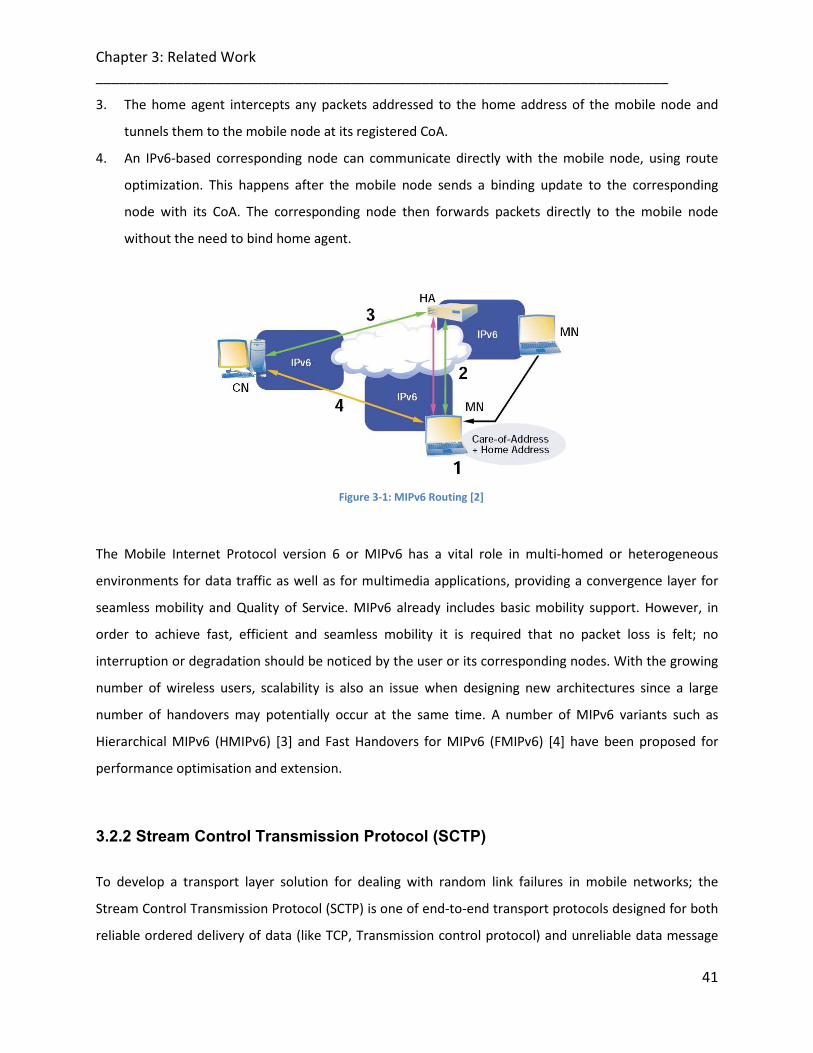
Chapter 3: Related Work ________________________________________________________________________
41
3. The home agent intercepts any packets addressed to the home address of the mobile node and
tunnels them to the mobile node at its registered CoA.
4. An IPv6-based corresponding node can communicate directly with the mobile node, using route
optimization. This happens after the mobile node sends a binding update to the corresponding
node with its CoA. The corresponding node then forwards packets directly to the mobile node
without the need to bind home agent.
Figure 3-1: MIPv6 Routing [2]
The Mobile Internet Protocol version 6 or MIPv6 has a vital role in multi-homed or heterogeneous
environments for data traffic as well as for multimedia applications, providing a convergence layer for
seamless mobility and Quality of Service. MIPv6 already includes basic mobility support. However, in
order to achieve fast, efficient and seamless mobility it is required that no packet loss is felt; no
interruption or degradation should be noticed by the user or its corresponding nodes. With the growing
number of wireless users, scalability is also an issue when designing new architectures since a large
number of handovers may potentially occur at the same time. A number of MIPv6 variants such as
Hierarchical MIPv6 (HMIPv6) [3] and Fast Handovers for MIPv6 (FMIPv6) [4] have been proposed for
performance optimisation and extension.
3.2.2 Stream Control Transmission Protocol (SCTP)
To develop a transport layer solution for dealing with random link failures in mobile networks; the
Stream Control Transmission Protocol (SCTP) is one of end-to-end transport protocols designed for both
reliable ordered delivery of data (like TCP, Transmission control protocol) and unreliable data message

Chapter 3: Related Work ________________________________________________________________________
42
(like UDP, User Datagram Protocol) [5], [6]. One major advantage of SCTP is that it has a multi-homing
function to achieve reliable transfer of data between two hosts.
Multi-homing function in SCTP protects an association from potential network failures by steering traffic
to alternate IP addresses. During the initiation of an association (An SCTP connection, called
association), SCTP binds one transport layer association to multiple IP addresses at each end of the
association. Since multi-homing function can handle multiple network interfaces with a list of IP
addresses, one of the listed IP addresses will be designated as the primary address during the initiation.
If the primary address repeatedly drops down (a process called failover), however, all traffic will be
transmitted to an alternate peer IP address. It will be useful in switching between different wireless
network interfaces when one of the wireless links is disconnected. In other word, the current SCTP uses
only one of the network interfaces at a time. SCTP’s failover mechanism is static and does not adapt to
application requirements or network conditions.
To better understand the way SCTP supports seamless handover between one network and the next,
consider the process as it occurs when a device supporting SCTP roams from one network to the next:
Consider the following scenario when a mobile node (MN) initiates an SCTP association with a
correspondent node (CN).After initiation of an SCTP association, the MN moves from Location 1 (Access
Point A) to Location 2 (Access Point B):
1. SCTP association has gained a set of IP addresses with IP address 1 for MN and IP address 2 for CN.
It is also assumed that the MN gets an IP address from its Access Point (AP1), with the help of IPv6
stateless address auto-configuration or DHCPv6.
2. While the MN is moving from AP1 to AP2, and is now in the overlapping region. In this phase, the
MN can obtain a new IP address 3 from its AP2 by using DHCPv6 or IPv6 stateless address auto-
configuration.
3. SCTP will bind the new 1P address to its address list of the corresponding SCTP association.
4. In this step, MN will send SCTP Address Configuration Change (ASCONF) (SCTP connection
information) to the CN. The MN may receive the responding ASCONF-ACK from the CN.
5. The MN is now in the multi-homing state. The old IP address (1P address 1) is still used as the
primary address, until the new IP address 3 is set to be the primary address by the MN.
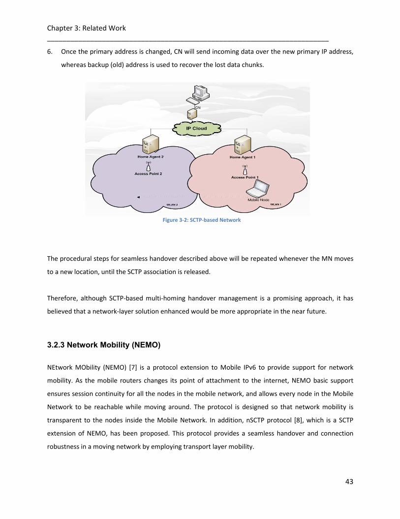
Chapter 3: Related Work ________________________________________________________________________
43
6. Once the primary address is changed, CN will send incoming data over the new primary IP address,
whereas backup (old) address is used to recover the lost data chunks.
Figure 3-2: SCTP-based Network
The procedural steps for seamless handover described above will be repeated whenever the MN moves
to a new location, until the SCTP association is released.
Therefore, although SCTP-based multi-homing handover management is a promising approach, it has
believed that a network-layer solution enhanced would be more appropriate in the near future.
3.2.3 Network Mobility (NEMO)
NEtwork MObility (NEMO) [7] is a protocol extension to Mobile IPv6 to provide support for network
mobility. As the mobile routers changes its point of attachment to the internet, NEMO basic support
ensures session continuity for all the nodes in the mobile network, and allows every node in the Mobile
Network to be reachable while moving around. The protocol is designed so that network mobility is
transparent to the nodes inside the Mobile Network. In addition, nSCTP protocol [8], which is a SCTP
extension of NEMO, has been proposed. This protocol provides a seamless handover and connection
robustness in a moving network by employing transport layer mobility.
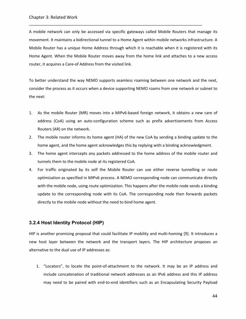
Chapter 3: Related Work ________________________________________________________________________
44
A mobile network can only be accessed via specific gateways called Mobile Routers that manage its
movement. It maintains a bidirectional tunnel to a Home Agent within mobile networks infrastructure. A
Mobile Router has a unique Home Address through which it is reachable when it is registered with its
Home Agent. When the Mobile Router moves away from the home link and attaches to a new access
router, it acquires a Care-of Address from the visited link.
To better understand the way NEMO supports seamless roaming between one network and the next,
consider the process as it occurs when a device supporting NEMO roams from one network or subnet to
the next:
1. As the mobile Router (MR) moves into a MIPv6-based foreign network, it obtains a new care of
address (CoA) using an auto-configuration scheme such as prefix advertisements from Access
Routers (AR) on the network.
2. The mobile router informs its home agent (HA) of the new CoA by sending a binding update to the
home agent, and the home agent acknowledges this by replying with a binding acknowledgment.
3. The home agent intercepts any packets addressed to the home address of the mobile router and
tunnels them to the mobile node at its registered CoA.
4. For traffic originated by its self the Mobile Router can use either reverse tunnelling or route
optimization as specified in MIPv6 process. A NEMO corresponding node can communicate directly
with the mobile node, using route optimization. This happens after the mobile node sends a binding
update to the corresponding node with its CoA. The corresponding node then forwards packets
directly to the mobile node without the need to bind home agent.
3.2.4 Host Identity Protocol (HIP) HIP is another promising proposal that could facilitate IP mobility and multi-homing [9]. It introduces a
new host layer between the network and the transport layers. The HIP architecture proposes an
alternative to the dual use of IP addresses as:
1. “Locators”, to locate the point-of-attachment to the network. It may be an IP address and
include concatenation of traditional network addresses as an IPv6 address and this IP address
may need to be paired with end-to-end identifiers such as an Encapsulating Security Payload
Chapter 3: Related Work ________________________________________________________________________
45
(ESP) and Security Parameter Index (SPI) so that packets are sent on the correct Security
Association (SA) for a given address. It may also include transport port numbers or IPv6 Flow
Labels as de-multiplexing context to aid the packet handling in the lower layers. Alternatively, it
may simply be a network address.
2. “Identifiers”, (endpoint, or host). Public cryptographic keys, of a public/private key pair, are used
as Host Identifiers, to which higher layer protocols are bound instead of an IP address. By using
these public keys (and their representations) as host identifiers, dynamic changes to IP address
sets can be directly authenticated between hosts, and if desired, strong authentication between
hosts at the TCP/IP stack level can be obtained easily.
HIP’s architecture [10] supports decoupling the transport layer (TCP, UDP, etc.) from the
internetworking layer (IPv4 and IPv6) by using public/private key pairs, to which higher layer protocols
are bound instead of an IP address. In upper-layer protocols (including TCP and ESP as shown in figure 3-
3) are bound to Host Identity Tags or HITs and not IP addresses. HIT is created to identify the sender and
recipient of a packet and acts as a hint for the proper public key to use. The HIP sublayer is responsible
for maintaining the binding between HITs and IP addresses. The SPI is used to associate an incoming
packet with the right HITs.
Figure 3-3: HIP-based layer
To better understand the way HIP supports seamless roaming between one network and the next,
consider the process as it occurs when a device supporting HIP roams from one network or subnet to
the next:

Chapter 3: Related Work ________________________________________________________________________
46
1. As the mobile node (MN) moves into another network, this system will be considered mobile as
its IP address can change dynamically for any reason like Dynamic Host Configuration Protocol
(DHCP), IPv6 prefix reassignments, or a Network Address Translation (NAT) device remapping its
translation. Likewise, a system is considered multi-homed if it has more than one globally
routable IP address at the same time.
2. HIP decouples the transport from the internetworking layer, and binds the transport
associations to the Host Identities (through the HIT as mentioned earlier)
3. HIP Maps the HITs to integrated IP packets. Thus will assure the IP address is protected from any
changing while communication is already ongoing.
4. Now the mobile node must send a HIP re-address packet to inform the peer of the new address.
In return, the peer must verify that the mobile node is reachable through these addresses. This
is especially helpful for those situations where the peer node is sending data periodically to the
mobile node (that is restarting a connection after the initial connection).
The Host Identities are used to create the needed IP Security Associations (SAs) and to authenticate the
hosts. However, the actual traffic between two HIP hosts is typical, and not necessarily protected with
integrated IP. When integrated IP is used, the actual traffic IP packets do not differ in any way from
standard IP packets.
HIP is implemented using public keys. Thus, HIP is being used in low-security situations where public key
computations are considered expensive. HIP can be used with very short Host Identity keys. Such use
makes the participating hosts vulnerable to connection hijacking attacks. Its mechanism should rely on
the routing system and not on providing cryptographic capabilities only.
3.2.5 SHIM6 (Site Multihoming by IPv6 Intermediation)
IETF Working Group proposed a multi-homing solution called “Shim6” to support IPv6 networks hosts
[11]. Shim6 is a sub-layer resides in a multi-homed site where multiple network service providers
advertise their IPv6 address prefixes. This allows the end hosts to have more than one IPv6 address
namely, being able to access multiple network service providers simultaneously.

Chapter 3: Related Work ________________________________________________________________________
47
Since it’s placed in the IP layer that is responsible to ensure providing local and remote hosts addresses
to the upper layer for the communications issues. Shim6 proposed architecture, defines two sub-layers
for the IP origin layer architecture, see figure 3-4.
Two terms are introduced:
1. “Identifiers” addresses pairs for the source and destination hosts which being used by the IP
End-point sub-layer to pass addresses to Transport and Application layers. These addresses are
presented to upper layers as ULID. When a host decides to communicate with a peer host, it
initially uses its ULID as the source address.
2. The other term known as “locators” which being used by the IP Routing sublayer that reserves
the actual address used with IP forwarding and routing techniques
Figure 3-4: Shim6 layer
To better understand the way SHIM6 supports seamless roaming between one network and the next,
consider the process as it occurs when a device supporting SHIM6 roams from one network to another:
When a host decides to contact a peer, it sends out packets using IP addresses. The packets are passed
from the IP Endpoint sub-layer to the IP Routing sub-layer, the endpoint identifiers are mapped to a
current pair of locators (pair of the source and destination addresses). In this Shim6 approach, the
endpoint identifiers and the locators are both IP addresses. The endpoint identifiers are the initial
addresses used between the two hosts. The locators are the set of IP addresses that are associated with
the endpoint.
The reverse mapping is applied to incoming packets, where the incoming locator pair is stripped off the
packet and the associated endpoint identity pair is associated with the packet, which is then passed to
the IP Endpoint sub-layer.

Chapter 3: Related Work ________________________________________________________________________
48
Figure 3-5:Shim6 multiple addresses
The shim6 mechanism that allows multi-homing by using multiple addresses. When communication
between the initially chosen addresses for a transport session is no longer possible, the host discovers
the current pair of address is not working properly since the host did not receive acknowledgement
packets from its peer host; it tries to find and select an alternative pair of addresses to carry on its
communications.
The selection of a locator pair is based on the application of the tables as described in [12]. The
approach also allows local policy settings to place a specific preference for each particular locator pair.
Therefore, the host selects the new locator pair from the table and exchange it with the faulted one.
Thus, shim6 layer makes it possible to switch to a different set of addresses without breaking current
transport protocol communication.
3.3 Related Work based on Fast Handover and Cross-Layer Solutions
Finding solutions for providing a certain level of quality for multimedia-based services during handover
process has attracted extensive researches. Different schemes were proposed and among the best-
known are those based on Fast Handover and Cross-layer design, bandwidth efficiency over provisioning
QoS as architectures and adaptive proposed solutions.
Chapter 3: Related Work ________________________________________________________________________
49
The scheme in [13] proposes a Link-layer handover algorithm that enhances the ranging of data streams
between the serving BS and the neighboring BSs, thus enables the MS to receive the data downstream at
the time it becomes synchronized with the neighboring BSs, the limitation of this scheme to downstream
only from BS to MS may lead to the deterioration of the communication quality as it requires a two
directions streams (down and upstream) handover enhanced solution.
The proposal Fast MAC-Layer Scanning in [14] introduce a cross-layer approach for fast handover, the
concept relies on the use of an extended MAC-layer information being sent to every channel between
the MS and the BSs, by including the IP address information to the MAC probing-messages, as this
reduces the time to scan all available channels. The scheme drawbacks, to the availability of the MS IP
address in this open way may grant the chance to an unsecure access device to obtain that address just
simply. The other drawback is the buffering of the probe message by an access device for a certain fixed
time before it sends it out may cause an additional delay for the MS to connect to its communicating
channel.
A seamless handover Mechanism in [15], through the backbone message, a BS sends information to
neighbor BSs. The MS selects candidate target BS based on the signal strength criteria and response time
of that BS.
The algorithm proposed in [16] aims to minimize the handover time by selecting one target BS and
performing both synchronization and downlink (DL)–MAP, simultaneously. However, this algorithm
assumes that the serving and target BS are transmitting on the same RF channel, which is not a practical
assumption in real wireless networks. Additionally, this algorithm does not consider the issue of
maintaining service quality for current connections by the target BS.
Chapter 3: Related Work ________________________________________________________________________
50
Another handover method proposed in [17], targets handover for load-balancing purposes by modifying
one of the management messages in the IEEE 802.16 standard. The modification allows advertising the
current load of the BS to help some MSs decide as to whether handover to another more lightly loaded
BS. In such case, they have suggested that the MS does not need to do any frequency scanning thus
reducing the handover time.
All the above techniques require either modifications to the existing standard or make some unrealistic
assumptions. Also, most of them ignore the service needs of the service flows running at the MS. This is a
crucial issue for IEEE 802.16 networks in which voice is not the only primary type of service flow.
Moreover, the handover algorithm [18], that takes into account the service type required by the
different service flow running at the MS, minimizing the handover time and selecting the best possible
target BS within the framework of IEEE 802.16e standard. The idea is that the MS only choose those BSs
with good and adequate signal strength values, which results in a better link-level communication with
the target BS and a lower bit error rate.
Bandwidth efficient video streaming upon scalable video coding (SVC) [19], the scheme enhanced
bandwidth efficiency of heterogeneous network’s SVC multicasting by transport the SVC cross layers
along multiple paths in a multicast mesh network. Since most user devices demand the lower layers of
an SVC, intermediate nodes with maximum fan-out should relay bitstreams, these layers. This approach
had successfully reduces the total bandwidth consumption of an SVC multicasting session. The drawback
of this approach that is only succeed with light traffic network, as If heavy load is be applied over a
network with losable links, the scheme will not perform well as expected.
To obtain low delay streaming using the SVC method in the peer-to-peer network, the proposed scheme
in [20] has combined use of multiple tree based push transport and en-route progressive rate adaptation

Chapter 3: Related Work ________________________________________________________________________
51
of SVC bitstreams to achieve low-latency video streaming. The proposed scheme reduces the chance of
link congestion by forwarding IP packets that carrying the SVC bits over several multicast trees, which
reduce the packet loss. The drawback of the scheme is its effectiveness in removing link congestion is
somewhat dubious as the en-route SVC streaming rate adaptation can only work when applying the
same types of user devices over the multicast network in the homogeneous network. If the scheme was
applied to heterogeneous network when there are different types of devices were applied, then here the
relaying nodes will have to forward most the entire SVC bitstreams to the peers without even having
another choice, this may result in the loss of the IP packets and huge consumption of data bandwidth
since most SVC are carried in multiple IP packets, that the loss of any of these packets will cause the
entire NAL units to be undecodable. Because of this, the scheme is only performing well under low traffic
load networks that have low percentage of packets loss.
Although there are many recently published works on multi-path routing issue over wireless networks,
none of them particularly addressed the problem of video applications multi-streams over WiMAX
networks when several interfaces are applied.
A cross-layer framework in WiMAX networks is proposed [21]. The proposed approach guarantees that
the required data rate is achieved for video streams, which is crucial for multimedia streaming
applications.
The proposed model can solve the channel-scheduling problem in the networks via using a server to
forward the data via the network end-points. The solution provides data rate guarantee for video
streams through demonstrating the model for unicast video stream and multicast techniques to extend
the capacity of the video server used. The drawback of this model, the data will be copied and
transmitted from one link to another in the network. Thus, will introduce additional maintenance costs.
Moreover, Authors of [22] propose a cross-layer framework for multicast throughput maximization in
wireless network. However, this framework is not suitable for video streaming application, where each
stream requires certain data rate for continuous video playback.

Chapter 3: Related Work ________________________________________________________________________
52
Novel multicast routing metrics are proposed in [23] and [24], but are only tested in 802.11-based
networks.
In [25], a multi-path video streaming system is proposed. Their assumption is that the video files may
have duplicate copies in different interfaces, thus the diversity of the sources can improve the quality of
the video service. However, this is not a common case, we prefer the video server to provide connection
that is more reliable.
It is interesting to note that the rate-distortion framework is widely used in recent video streaming over
wireless network research [26–29]. These works focus on minimizing the distortion by video rate
allocation or multipath routing. The multi-path routing requires special division coding. Moreover, the
current WiMAX scheduling does not support multiple path routing.
The cross layer scheme in [30] is only focusing on how to reduce the packets retransmission delay in the
MAC and Logical link (LL) layers, both layers queues connected to each other in the protocol stack.
Therefore, no additional work enhanced to the protocol stack to combine both layers.
Figure 3-6: MAC and Logical layers Queuing
However, packet loss in the wireless link in MAC is not considered in these controls. This needs more
improvement to be added. Moreover, this method was specialized for IEEE 802.11 only.
The algorithm in [31] takes into account maintaining the existing service flows and their QoS parameters
when performing handover to another target BS. The drawbacks of this scheme, the RSSI measurement
is the only factor considered in selecting the target BS. In addition, it did not address how the handover
time may affect higher layer connections in terms of their QoS parameters such packet delay and packet
loss rate.

Chapter 3: Related Work ________________________________________________________________________
53
The proposed work in [32] can be exploited to handover application flows among the most appropriate
interfaces and access networks dynamically to achieve end-to-end seamless handover, robust
communications for mobile users. A MN can be equipped with multiple network interfaces via two
interfaces to the correspondent node. The drawbacks of the designed system, is the handover process
between the networks is copying the same information transmitted from the first interface to the
second. In addition, the route optimisation was not investigated in the work.
The IETF plays an essential role in IP-based mobility management. As known, Mobile IPv6 (MIPv6) [33] is
the standard for IPv6 mobility support. Unfortunately, MIPv6 in its current form does not support
advanced multihoming beyond handing over all the flows from one interface to another uniquely.
A number of MIPv6 variants such as Hierarchical MIPv6 (HMIPv6) [34] and Fast Handovers for MIPv6
(FMIPv6) [35] have been proposed for performance optimisation and extension.
In particular, Network Mobility (NEMO) [36] extends the IP mobility support from a single mobile host
(MH) to a completely mobile network managed by a mobile router. However, MIPv6 and these variants
have not addressed advanced flow handovers in a multihoming context.
Following the end-to-end principle in the Internet design, the IETF has concentrated on the user-centric
approach though there is a need for the network-supported approach [37] and thus the Network-based
Localised Mobility Management (NETLMM) WG has been launched. Recently, the Mobile Nodes and
Multiple Interfaces in IPv6 (MONAMI6) WG has been standardising MIPv6/NEMO-based host
multihoming mechanisms to facilitate flow handovers for multi-homed MNs.
Multiple Care-of-Addresses (CoAs) registrations are allowed in [38] so that a single Home Address (HoA)
can be bound with more than one CoA through a pair of Binding Update (BU) and Binding
Acknowledgement (BA) messages. A major drawback in this proposal is that only user-initiated flow
handovers were addressed as a BU is always sent from a MN to its Home Agent (HA), although both
user- and network-initiated flow handovers are desired and should be supported.

Chapter 3: Related Work ________________________________________________________________________
54
From the related work mentioned in the previous section, those works utilise end-to-end connection for
signalling handoffs. The end-to-end approach would reduce the delay and eliminate the cost that exists
in the handover management protocols. On the other hand, the end-to-end paradigm lacks the support
from network intelligence that can be very beneficial for overall QoS provision.
After all, the multihoming schemes were mainly designed to enable transmissions to alternate IP
addresses for survivability when the primary IP address becomes unavailable. There is little, if any, work
aims to enable handover of different application flows among several layers and interfaces of a single
multi-homed node. Over which most IP applications are currently running. Therefore, although
multihoming handover management is a promising approach, we believe that a cross layer solution that
includes network-layer component e.g., enhanced MIPv6 would be more appropriate in the near future.
Our proposals present a fast handover scheme, which reduces HO latency in WLAN and WiMAX
scenarios. The MS will follow the scanning/ranging steps with eliminated number of BSs. As the
connection quality will be degraded for a reason or another, our schemes will try to solve some channel
issues such the traffic congestion and traffic routing without affecting the HO prospects as in the other
proposed schemes.
3.4 Multi-homed Networks Handover Performance Requirements
To achieve a seamless handover in ubiquitous multi-homed networks, the following three requirements
should be satisfied [39]:
1. Prompt and reliable detection of degradation in wireless link quality.
2. Elimination of handover processing delay on several protocol stack layers (a need for a cross layer
design).
3. Selection of a better network.
Mobile Nodes (MNs) will freely move between wireless networks with different IP subnets. In such a
wireless environment, wireless link quality frequently fluctuates according to the change in time and
spaces. As a result, the degradation of wireless link quality has direct effect on application quality.
Particularly, in real-time application such as voice over IP (VoIP), the detection delay for the degradation

Chapter 3: Related Work ________________________________________________________________________
55
of wireless link quality causes serious degradation of application quality. Therefore, to achieve “1”, an
MN needs to periodically and reliably detect the degradation of wireless link quality. Next, when an MN
with single wireless interface moves between different IP subnets, the MN invariably experiences a
period time during which it is unable to send and receive packets due to both link switching delays and
IP protocol operations.
The necessary process for handover between different IP subnets is as follows: (1) Channel scan to search for a new network access point (AP). (2) Association with the new network AP. (1), (2) are done in MAC and PHY layers associations.
(3) Obtainment of an IP address in the new network.
(4) Notification of the new IP address to a corresponding node (CN).
((3), (4) are done in the Network layer). In addition, considering acquisition of an IP address from DHCP
and notification of the new IP address to CN (one-way delay) during Network layer handover, it is clear
that the disruption period caused by Link and Network layers handover processes severely impacts the
communication quality of real-time application. Therefore, in (2), it is essential to remove the disruption
period in handover. In ubiquitous networks, an MN needs to execute handover to a better AP. However,
as the MN freely moves between
For an example, a network with relatively small coverage, the link quality of the network frequently
fluctuates. Therefore, in (3), an MN needs to select a better AP than the current AP at handover
according to wireless link quality.
3.4 References
[1] P. Schmitz, G. Weaver, “MIPv6: New Capabilities for Seamless Roaming Among Wired, Wireless, and
Cellular Networks”, Intel Developer Update Magazine, September 2002.
[2] D. B. Johnson, C. Perkins, J. Arkko, “Mobility support in IPv6”, IETF, June 2004.
[3] H. Soliman, C. Catelluccia, K. E. Malki, Ludovic Bellier, “Hierarical mobile IPv6 mobility management
(HMIPv6)”, IETF, August 2005.
[4] M. K. Park, J. Y. Lee, B. C. Kim, D. Y. Kim, “Design of Fast Handover Mechanism for Multiple
Interfaces Mobile IPv6”, IEEE ISWPC, 2008.
[5] R. Stewart, Q. Xie, K. Morneault, et al., “stream control transmission protocol”, IETF, Oct 2000.

Chapter 3: Related Work ________________________________________________________________________
56
[6] S. J. Koh, M. J. Chang, M. Lee, “mSCTP for soft handover in transport layer”, IEEE Communications
Letters 8 (3) (2004) 189-191.
[7] V. Devarapalli, R. Wakikawa, A. Petrescu, P. Thubert, “Network mobility (NEMO) basic support
ptorocol”, IETF, Jan 2005.
[8] P. Behbahani, V. Rakocevic, “nSCTP: A New Transport Layer Tunnelling Approach to Provide
Seamless Handover for Moving Network”, IFIP 2007.
[9] R. Moskowitz, P. Nikander, “Host Identity Protocol (HIP) Architecture”, Network Working Group,
May 2006.
[10] R. Moskowitz, P. Nikander, T. Henderson, “Host Identity Protocol”, Network Working Group, April
2008.
[11] J. Abley, M. Bagnulo, “Applicability Statement for the Level 3 Multihoming Shim Protocol (Shim6)”,
Network Working Group, July 2007.
[12] M. Bagnulo, “Default Locator-pair selection algorithm for the SHIM6 protocol”, Network Working
Group, July 2007.
[13] Sik Choi, Gyung-Ho Hwang, Taesoo Kwon, Ae-Ri Lim, and Dong-Ho Cho, “Fast Handover Scheme for
Real-Time Downlink Services in IEEE 802.16e BWA System”, Vehicular Technology Conference (2005
IEEE 61st), June 2005, Volume 3, pp. 2028 – 2032.
[14] Sebastian Speicher and Christian Bünnig, “Fast MAC-Layer Scanning in IEEE 802.11 Fixed Relay Radio
Access Networks”, ICN/ICONS/MCL, 2006. 23-29 April 2006.
[15] Kyung-ah K, Chong-Kwon K, Tongsok K, “A seamless handover Mechanism for IEEE 802.16e
Broadband Wireless Access”[C]. ISPC 2004, August 2004.
[16] D. Lee, K. Kyamakaya and J. Umondi”Fast Handover Algorithm for IEEE 802.16e Broadband Wireless
Access System”, IEEE Computer and Communications Socities Conference (INFOCOM), vol.3, pp.
985-992, April 1995.
[17] S. Lee and Y. Han “A Novel Inter-FA Handover Scheme for Load Balancing in IEEE 802.16e System”,
IEEE Computer and Communications Socities Conference (INFOCOM), vol.3, pp. 985-992, April
1995.

Chapter 3: Related Work ________________________________________________________________________
57
[18] Hossam Fattah and Hussein Alnuweiri “A New Handover Mechanism for IEEE 802.16e Wireless
Networks”, IEEE 2008.
[19] Che-Min Lin, John K. Zao, Wen-Hsiao Peng, Chia-Chi Hu, Hsin-Min Chen, Chun-Kai Yang “Bandwidth
Efficient Video Streaming Based Upon Multipath SVC Multicasting”, IEEE 2008.
[20] P. Baccichet, T. Schierl, T. Wiegand, B. Girod. “Low Delay Peer-to-Peer Streaming Using Scalable
Video Coding”. Proc. IEEE International Conference on Image Processing (ICIP), pp. 1-22, 2007.
[21] F Xie, K. A. Hua, N. Jiang, “A cross-layer framework for video-on-demand service in multi-hop WiMax mesh networks”, 1615–1626, Elsevier, Computer Communications 31 (2008).
[22] J. Yuan, Z. Li, W. Yu, B. Li, A cross-layer optimization framework for multihop multicast in wireless
networks, in: IEEE Journal on Selected Areas of Communication (JSAC), vol. 24, Issue 11, 2006, pp. 0733–8716.
[23] S. Roy, D. Koutsonikolas, S. Das, Y.C. Hu, High-throughput multicast routing metrics in wireless mesh networks, in: Proceedings of the 26th IEEE International Conference on Distributed Computing Systems (ICDCS’06), 2006, p. 48.
[24] P.M. Ruiz, F.J. Galera, C. Jelger, T. Noel, Efficient multicast routing in wireless mesh networks
connected to Internet, in: Proceedings of the First international Conference on integrated internet Ad Hoc and Sensor Networks. InterSense’06, vol. 138, ACM Press, New York.
[25] D. Li, Q. Zhang, C.N. Chuah, S.J. Ben Yoo, Error resilient concurrent video streaming over wireless
mesh networks, in: Proceedings of Packet Video Workshop, April, 2006. X. Zhu, B. Girod, Video streaming over wireless networks, in: Proceedings of the European Signal Processing Conference, EUSIPCO- 07, Poznan, Poland, September, 2007.
[26] X. Zhu, B. Girod, Video streaming over wireless networks, in: Proceedings of the European Signal
Processing Conference, EUSIPCO- 07, Poznan, Poland, September, 2007. [27] X. Zhu, P. Agrawal, J.P. Singh, T. Alpcan, B. Girod, Rate allocation for multi-user video streaming over
heterogenous access networks, Proceedings of the ACM Multimedia, MM’07, Augsburg, Germany, September, 2007.
[28] X. Zhu, J.P. Singh, B. Girod, Joint routing and rate allocation for multiple video streams in ad hoc wireless networks, Journal of Zheijang University Science A 7 (5) (2006) 900–909.
[29] Shiwen Mao, Y. Thomas Hou, Xiaolin Cheng, Hanif D. Sherali, Scott F. Midkiff, Multi-path routing for
multiple description video over wireless ad hoc networks, in: Proceedings of IEEE INFOCOM 2005,
Miami, FL, March 13–17, 2005, pp. 740–750.
[30] S. Ohzahata), S. Kimura, Y. Ebihara and K. Kawashima, “A Cross-Layer Retransmission Control for
Improving TCP Performance in Wireless LAN”, IEICE TRANS. COMMUN., VOL.E90–B, NO.8, 2007.
Chapter 3: Related Work ________________________________________________________________________
58
[31] H. Fattah and H. Alnuweiri, “A New Handover Mechanism for IEEE 802.16e Wireless Networks”,
IEEE 2008.
[32] Q. Wang, R. Atkinson, J. Dunlop, “Design and evaluation of flow handoff signalling for multi-homed
mobile nodes in wireless overlay networks”, Elsevier, 1647–1674, Computer Networks 52 (2008).
[33] D.B. Johnson, C. Perkins, J. Arkko, Mobility support in IPv6, IETF RFC 3775, June 2004.
[34] H. Soliman, C. Catelluccia, K.E. Malki, Ludovic Bellier, Hierarchical mobile IPv6 mobility management
(HMIPv6), IETF RFC 4140, August 2005.
[35] R. Koodli (Ed.), Fast handovers for mobile IPv6, IETF RFC 4068, Jul 2005.
[36] V. Devarapalli, R. Wakikawa, A. Petrescu, P. Thubert, Network mobility (NEMO) basic support
protocol, IETF RFC 3963, January 2005.
[37] M. Yabusaki, T. Okagawa, K. Imai, Mobility management in all-IP mobile network: end-to-end
intelligence or network intelligence? IEEE Communications Magazine 43 (2) (2005), supl. 16–supl.
24.
[38] R. Wakikawa, T. Ernst, K. Nagami, Multiple care-of addresses registration, IETF Internet Draft.
<draft-wakikawa- mobileip-multiplecoa-05.txt>, work in progress, February 2006.
[39] Wu Xing-feng , Liu Yuan-an, “A Survey of WLAN QoS Systems Based on IEEE 802.11”, IJCSNS
International Journal of Computer Science and Network Security, VOL.7 No.3, March 2007.

Chapter 4: Design of ISP ________________________________________________________________________
4
Chapter 4
59
DESIGN OF INTERFACE SELECTION PROTOCOL (ISP) For IEEE802.11 & IEEE802.16
This chapter provides details of various aspects of the proposed multi-homing routing protocol (ISP)
such as the route discovery process, route maintenance, packets format for Probe message and Route
parameters used within route discovery. Additionally, the implementation and modelling framework
used for simulation purposes of ISP, based on a cross-layer information exchange, is also explained in
detail.
4.1 Proposed Multi-homing Protocol
ISP is a new reliable routing protocol, which is essentially a succession of multi-homing interface
selection protocols. ISP is able to provide a reliable communication route with assurance of good
bandwidth (data-rate), lower delay and route optimization. The design of an ISP is based on a novel
cross layer information exchange mechanism, which enables the routing protocol to use various
network related parameters from different layers (Link/ Physical layers) across the protocol suite for
decision making at the Network layer. The selected route under the ISP protocol is based on the most up
to date link-layer information. Therefore, such a route is not only reliable in terms of route optimization
but it also fulfils the application demands in terms of throughput and delay.
Contrary to the majority of previous solutions for routing in multi-homing wireless networks, ISP is
adaptive in terms of the route selection process. The default route (Which uses the optimum values of
cross layer parameters) can always be overridden by changing the parameters according to the type of
applications. In other words, it implies that between the same source and destination there might be
different paths.

Chapter 4: Design of ISP ________________________________________________________________________
60
For packet forwarding if there are different types of applications active on the source and destination.
The route maintenance process often becomes extremely challenging due to the highly variable nature
of wireless medium (interference, distance between transmitter and receiver etc) and frequent
movement of participating nodes in a wireless network causing topological changes in the network. To
cope with this issue, ISP always maintains an alternative route in parallel to the primary route, to ensure
that at every node if the packet forwarding fails for some reason on the primary route, the alternative
path can be used instead of initiating a new route rediscovery process.
4.2 ISP: In Details
This section presents details of various features of ISP protocol including packet formats, route discovery
process and route maintenance. Likewise, the cross layer information exchange framework and various
aspects of routing under ISP are also highlighted.
4.2.1 Packets Format
The ISP uses control packets in each direction of the route discovery process. The control messages sent
from source to the destination and sent in reverse direction as well, these messages are called Probe
Messages. The format of the control messages is discussed as follows
4.2.1.1 Probe Message The Probing messages carry information about the state of connectivity between the source and
destination nodes (peers), such as whether the sender has seen any traffic from the peer recently.
When the peer receives a message that indicates a problem, it assists the process by starting its own
parallel exploration to the other direction, again sending information about the recently received traffic
or messages. The Probe message packet consists of the following fields; Source and Destination
Addresses, Type, Probe sent No, Probe received No, State and Route Parameters.
Source and destination addresses: contain IPv6 addresses used to send the probe.
Type: identifies the Probe message whether it (source to destination or destination to source)

Chapter 4: Design of ISP ________________________________________________________________________
61
Probe sent No and Probe received No: indicates the number of sent/received probes.
Route Parameters: mainly based on many variable factors (Bandwidth (data rate), Delay, QoS, etc.). State: used to inform the receiver (peer) about the state of the sender. It has three logical values:
a. Operational: indicates that both sender and receiver have no problem in communicating to each
other.
b. Exploring: indicates that the sender has a problem in communicating with the receiver.
c. ExploringOK: indicates the sender has no problem communicating with the receiver, since it
receives some packets from the receiver, but the receiver either has a problem or has not yet
confirmed to the sender that the problem has been solved.
Figure 4-1: Probe Message Format
When a source node decides that it needs to explore for an alternative address pair to its peer node, it
will initiate a set of Probe messages, in sequence, until it gets a Probe message from that peer indicating
that:
(1) The peer has received one of source’s Probe messages.
(2) Peer’s Probe message sent back to source.
The same steps applied when the peer starts the process.
4.2.2 Route Parameters (QoS)
ISP relies on different Quality of Service (QoS) parameters to provide guarantees on the ability of the
network to deliver predictable results and determining an optimum route based on a specific request of
a network condition. The parameters are: Available Bandwidth, Delay.

Chapter 4: Design of ISP ________________________________________________________________________
62
4.2.2.1 Available Bandwidth (Data Rate)
The Bandwidth availability represents the capacity of the connection. The greater the capacity, the more
likely that greater network performance will follow. This performance also depends on other factors,
such as latency.
The available bandwidth information can be collected using a cross layer interface among the Network-
MAC-PHY layers as shown in Figure 4-2. In practical, the most implementation and most the algorithms
assumptions, the bandwidth is implemented at the MAC layer. Therefore, it can be estimated at the
MAC layer given the information about the traffic channel’s Bandwidth value. The estimated value of
bandwidth can be passed to the network layer (to the ISP protocol) via a cross layer interface. The
bandwidth has fluctuation in the traffic rate in case of the bandwidth-limit is not used at the MAC layer.
In case if a bandwidth adaptation method [1] is used which will change the value of bandwidth-limit
adaptively according to the variations in the channel conditions of a wireless network, there will be
fluctuations in the values of bandwidth even if the traffic rate remains constant. During data
transmission, any changes in the nodes parameters could affect the current route. Therefore, each node
in the data path should monitor the route status of the next and previous network condition.
Accordingly, the route could be changed due to changing in the participating nodes status. This is a
route optimization process. When one of the route interfaces is down, the alternative interface will take
over according to the route forwarding, which is done by the previous and next switched interfaces
(comparing to the node that suffer from bandwidth degrading).

Chapter 4: Design of ISP ________________________________________________________________________
63
Figure 4-2: Cross-Layer Model
4.2.2.2 Latency (Delay)
The delay is an important element in wireless sensitive services (multimedia applications like video and
voice) as it can cause problems for all data services where the preservation of the sequence of packets is
extremely important. The delay is affected by many factors at various layers of the protocol suite; each
layer has different protocols specifications that affect the total delay within the whole system.
The optimum delay that occurs within the wireless networks is a result of the following:
System’s Delay = (Transport-Layer Delay) + (IP Layer Delay) + (MAC-Sub-layer Delay). If the System’s
Delay is more than 400ms then it is generally not acceptable for real time services. The following table
gives effect of various delay values.

Chapter 4: Design of ISP ________________________________________________________________________
64
Table 4-1: Description of Various Delay Values
Transport-Layer Delay and IP-Layer Delay constitute a very small part of the overall system delay and are
mostly dependent on the traffic rate generated by applications. The delay at these two layers rises if it
has more traffic and queues in order to process.
On the other hand, MAC delay constitutes the major part of overall system delay. In general, the MAC
Layer manages and maintains communications between 802.11 nodes by coordinating access to a
shared radio channel and utilizing protocols that enhance communications over a wireless medium.
MAC delay represents the total of queuing and contention delays of data packets received by the WLAN-
MAC from higher layer. As for each packet, the delay is recorded when the packet is sent to the physical
layer for the first time. Thus, the delay, allows the mobile node (MN) to detect whether the condition of
the wireless link being used is becoming better or worse and may enable the MN to determine when the
handover process should be started before packet loss actually occurs.
The Link delay is calculated after reception of every Probe message between packet creation time
information and reception time. Delay is an additive metric, thereby; the delay of a route is the
summation of delays of all available interfaces on the routes. The instantaneous values of the delay
fluctuate with time. The term end-to-end is used for an average measure of performance, between peer
nodes in a network, typically between source and the destination. The end-to-end delay is therefore the
total delay that a data packet experiences as it is travelling through a network. This delay is built up by
time spent in packet queues, forwarding delays, propagation delay (the time it takes for the packet to
travel through the medium) and time needed for the retransmissions packets, in case they were lost.
Chapter 4: Design of ISP ________________________________________________________________________
65
4.2.3. Crosse Layer Design for Optimization Wireless Networks
4.2.3.1 Cross-Layer Design; An overview Cross Layer design aims at performance enhancements in wireless networks, by bringing design changes
in the Standard protocol architecture. Its solutions offer promising possibilities of joint optimization
across the protocol suite. However, due to the variety of network applications and complexity of the
underlying networking protocols, there is a great deal of future generation Multi-homed networks
envisioned to be a combination of diverse but complementary access technologies. The integration of
existing and emerging heterogeneous wireless networks requires the design of intelligent failure
detection and recovery schemes to enable mobile users to switch between networks and experience
uninterrupted service continuity anywhere, anytime.
4.2.3.2 Cross Layer Solution for ISP
The ISP protocol relies on information from the MAC sub-layer. However, according to the Standard
protocol architecture the routing layer does not have access to such parameters. Therefore, the routing
protocol can not have such an interaction without a cross layer information exchange. As a result, the
Standard protocol architecture the routing protocol is not able to make intelligent decisions involving
parameters from various layers. In order to achieve this goal the ISP protocol relies on cross layer
information exchange as shown in Figure 4-2. The MAC sub-layer conveys preferences in the form of
two parameters to the routing protocol. By default, the routing protocol selects a route using an equal
rate to the two parameters.
However, various applications can override the default settings by modifying these parameters. This
interface forms a top-to-bottom cross layer information exchange.
Similarly, the MAC sub-layer conveys the run time information about the current bandwidth to the
routing layer.
Chapter 4: Design of ISP ________________________________________________________________________
66
Route Parameters Preferences:
The ISP protocol selects an optimum route using a combined route parameters of available bandwidth
with minimum delay. The interface selection process is adaptive and closely matches the application
connection requirements; in addition, different types of applications have dissimilar requirements. An
optimum route is always selected by default; however, various applications can convey their individual
requirements to the ISP protocol using two parameters: bandwidth and delay, for an example; a video
conferencing application requires larger bandwidth and is also delay sensitive. In this case, ISP
parameters values for a video conferencing application will be examined with assigned thresholds if they
correspond to the application. As other application, which requires relative lower bandwidth but higher
route reliability and is sensitive to network delays can configure these parameters according to the
application requirements.
The ISP protocol uses the information given by applications in the form B1 and D1 to calculate the
bandwidth and the delay for selecting a route using the following equations:
Route Parameters = B1 ×Bandwidth + D1 × Delay (1)
This equation implies that a different route may be selected between the same source and destination
nodes if different types of applications are hosted at these nodes.
4.2.3.4 Route Process The protocol works as a principle of route discovery, i.e. the new routes are discovered only when they
are needed for better communication. The Probe messages are responsible for the selection of an
optimum route from the source node to destination node with assurance of allocation of the better
bandwidth and lower delay. The source node broadcasts Probes to find available path to the
destination. The destination unicasts Probes after evaluating and measuring the best path. In addition to
choose the “best path”, the destination node also selects an “alternative path” by following a reverse
methodology from destination to source node. The operation in this situation can be defined as
bidirectional, when a packet sent with one of the addresses in the source field and the other in the
destination field reaches the destination, and vice versa.
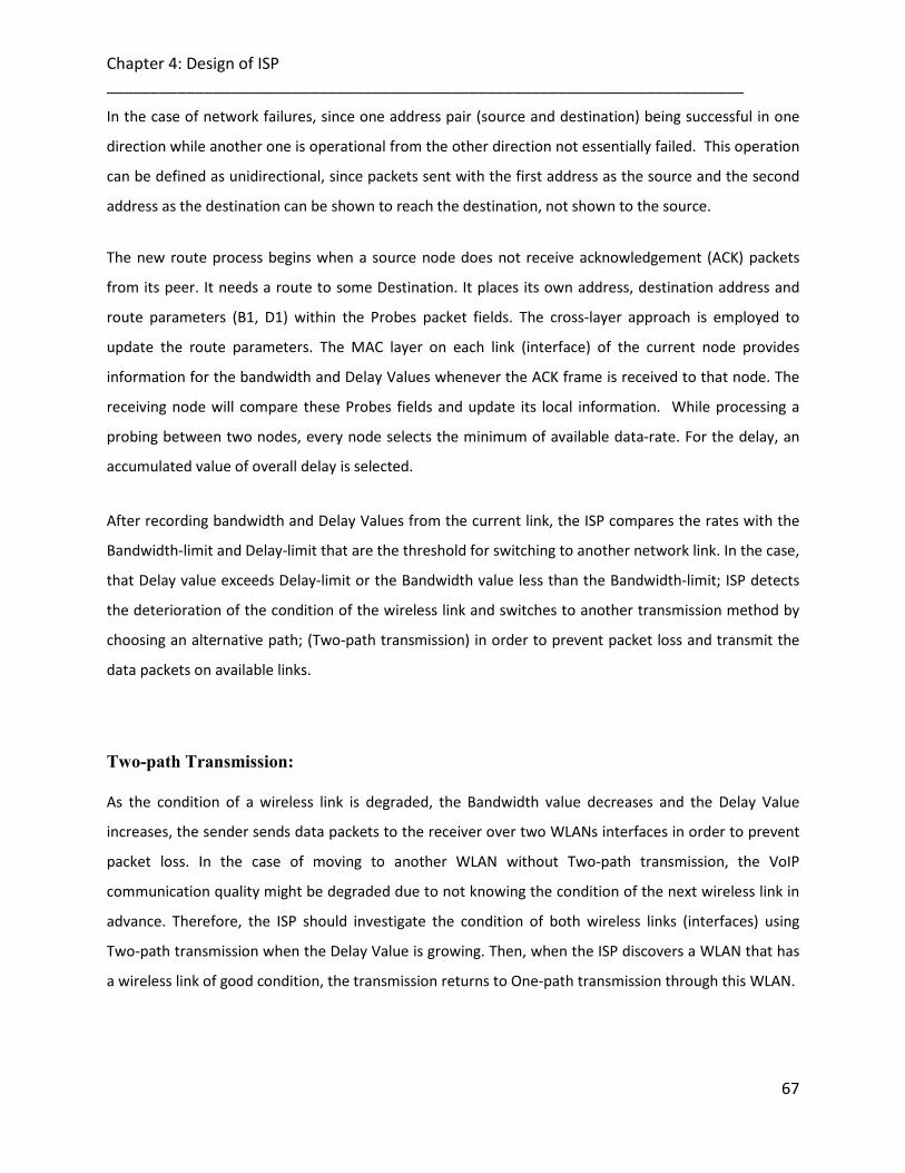
Chapter 4: Design of ISP ________________________________________________________________________
67
In the case of network failures, since one address pair (source and destination) being successful in one
direction while another one is operational from the other direction not essentially failed. This operation
can be defined as unidirectional, since packets sent with the first address as the source and the second
address as the destination can be shown to reach the destination, not shown to the source.
The new route process begins when a source node does not receive acknowledgement (ACK) packets
from its peer. It needs a route to some Destination. It places its own address, destination address and
route parameters (B1, D1) within the Probes packet fields. The cross-layer approach is employed to
update the route parameters. The MAC layer on each link (interface) of the current node provides
information for the bandwidth and Delay Values whenever the ACK frame is received to that node. The
receiving node will compare these Probes fields and update its local information. While processing a
probing between two nodes, every node selects the minimum of available data-rate. For the delay, an
accumulated value of overall delay is selected.
After recording bandwidth and Delay Values from the current link, the ISP compares the rates with the
Bandwidth-limit and Delay-limit that are the threshold for switching to another network link. In the case,
that Delay value exceeds Delay-limit or the Bandwidth value less than the Bandwidth-limit; ISP detects
the deterioration of the condition of the wireless link and switches to another transmission method by
choosing an alternative path; (Two-path transmission) in order to prevent packet loss and transmit the
data packets on available links.
Two-path Transmission:
As the condition of a wireless link is degraded, the Bandwidth value decreases and the Delay Value
increases, the sender sends data packets to the receiver over two WLANs interfaces in order to prevent
packet loss. In the case of moving to another WLAN without Two-path transmission, the VoIP
communication quality might be degraded due to not knowing the condition of the next wireless link in
advance. Therefore, the ISP should investigate the condition of both wireless links (interfaces) using
Two-path transmission when the Delay Value is growing. Then, when the ISP discovers a WLAN that has
a wireless link of good condition, the transmission returns to One-path transmission through this WLAN.

Chapter 4: Design of ISP ________________________________________________________________________
68
Figure 4-3: Two-path Transmission algorithm diagram
4.2.3.5 Route Maintenance Mechanism
The primary route may fail for anyone of the potential reasons as shown in Figure 4-4, e.g. one of the
links between the source and destination (the link between node A and node B) may break and as a
result the primary route no more exists. The route maintenance procedure is triggered whenever the
selected route between source and destination is broken or changed due to the nodes’ mobility or
handover. The node maintains the route by initiating a Send-timer (Send Timeout seconds) and a Keep-
alive timer (Keep-alive Timeout seconds). Source node starts a Keep-alive timer to keep track of the
availability of the selected route. The Keep-alive timer reflects the requirement that when this node
receives a data packet there should a similar response towards the peer. Thereby, if data packets from
source do not arrive at the destination node and timer expires, it is assumed that the selected route
between source and destination is lost or broken. In this case, source/destination node selects the best

Chapter 4: Design of ISP ________________________________________________________________________
69
available, alternative route and broadcasts its packets within Send Timeout seconds. The Send-timer
reflects the requirement that when this node sends a packet there should be some return traffic.
Figure 4-4: Simulated Scenario for the Route between Node A and Node B
It is important to note that the route maintenance can be initiated at the destination node.
However, in general a mobile node may communicate with a certain destination for some time using a
certain path and after a while it may stop communication. In this case, although the communication is
successfully done but when the applications stop communication any further, the ISP module at the
destination would check its timer and as soon as the timer expires, it would think that there is a
disconnection in the primary route. Therefore, it would automatically go for alternative route and send a
new Probe message to the source informing it about the alternative path. In this case the destination
node would set another timer because the source may not want to communicate any further. There is a
strong reason for setting a timer timeouts for the alternative path: in scenarios like the one stated above
when the source is no more communicating; setting timeout for alternative path would not cause the
destination node to go into a never ending process of alternative route discoveries and sending Probe
messages.
The following section describes in detail the functional methods of ISP.
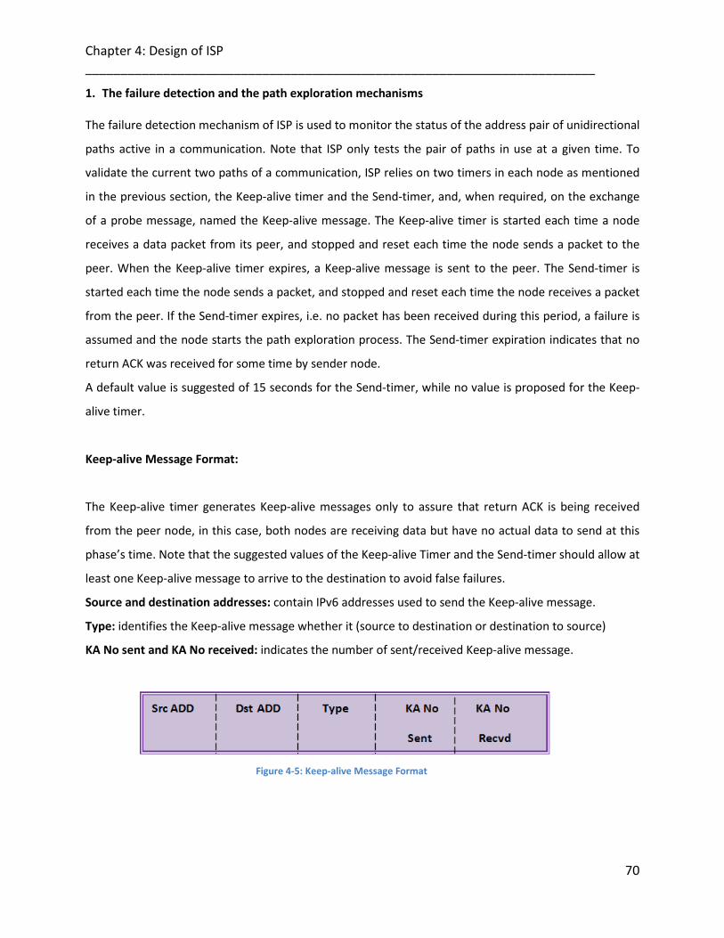
Chapter 4: Design of ISP ________________________________________________________________________
70
1. The failure detection and the path exploration mechanisms
The failure detection mechanism of ISP is used to monitor the status of the address pair of unidirectional
paths active in a communication. Note that ISP only tests the pair of paths in use at a given time. To
validate the current two paths of a communication, ISP relies on two timers in each node as mentioned
in the previous section, the Keep-alive timer and the Send-timer, and, when required, on the exchange
of a probe message, named the Keep-alive message. The Keep-alive timer is started each time a node
receives a data packet from its peer, and stopped and reset each time the node sends a packet to the
peer. When the Keep-alive timer expires, a Keep-alive message is sent to the peer. The Send-timer is
started each time the node sends a packet, and stopped and reset each time the node receives a packet
from the peer. If the Send-timer expires, i.e. no packet has been received during this period, a failure is
assumed and the node starts the path exploration process. The Send-timer expiration indicates that no
return ACK was received for some time by sender node.
A default value is suggested of 15 seconds for the Send-timer, while no value is proposed for the Keep-
alive timer.
Keep-alive Message Format:
The Keep-alive timer generates Keep-alive messages only to assure that return ACK is being received
from the peer node, in this case, both nodes are receiving data but have no actual data to send at this
phase’s time. Note that the suggested values of the Keep-alive Timer and the Send-timer should allow at
least one Keep-alive message to arrive to the destination to avoid false failures.
Source and destination addresses: contain IPv6 addresses used to send the Keep-alive message.
Type: identifies the Keep-alive message whether it (source to destination or destination to source)
KA No sent and KA No received: indicates the number of sent/received Keep-alive message.
Figure 4-5: Keep-alive Message Format

Chapter 4: Design of ISP ________________________________________________________________________
71
Once a node has detected a failure, the node starts sending probe messages to investigate if the current
locator pair is working properly. If there is no response during a period of time associated to a timer
called Retransmission timer (TRTX). The node starts investigating the other available pairs of addresses
by sending probe messages to the pairs and then picks up the selected one according to a selection
mechanism, as shown in Figure 4-6.
Figure 4-6: Address Selection Mechanism
2. Congestion Issue
ISP does not include any mechanism for detecting congestion. Severe congestion in the network is
considered by ISP as a failure. If packets stop reaching the node for a Send timer period, due to

Chapter 4: Design of ISP ________________________________________________________________________
72
congestion, ISP assumes a failure has occurred (a false positive) and starts the exploration mechanism.
We argue that this is an appropriate behaviour when network congestion is such that the time during
which the path is unavailable exceeds the threshold set by the application type using it.
4.3 Summary
This chapter provided details of various aspects of the proposed Interface Selection Protocol (ISP) in
multi-homed wireless network; such as the route discovery process, route maintenance, packets format
for Probe message and Route parameters used within route discovery. Moreover, the implementation
and modelling framework used for simulation purposes of ISP that is based on a cross-layer information
exchange was also explained with details.
Chapter 5: Implementation of ISP in OPNET Modeler ________________________________________________________________________ 5
Chapter 5
73
Implementation OF ISP IN OPNET MODELER
This chapter is divided into two parts. The first part explains the model designs in detail, some basics
details on the actual simulation program (OPNET Modeler) [1].The second part describes the ISP model
in OPNET modeller 14.0.
The second part consists of three main sections. Initially, the ISP will be introduced, with the model
principles discussed in Chapter 4, highlighted. Secondly, the node design will be discussed in great
details with respect to the ISP node operation, simulation parameters and testing. Then a discussion will
involve the adaptation of the ISP principles in a wireless node as presented in OPNET Modeler, also the
newly introduced simulation parameters together with all the old parameters provided by the wireless
node in OPNET Modeler will be identified and explained. The third section involves proof of operation of
the model and how a user can setup a fully operational ISP project for investigating the performance of
the ISP protocol.
5.1 OPNET Modeler
OPNET is a Modeler program that has a hierarchical method of designing models for network simulation.
The hierarchy begins with the project model editor, where either the standard library models or a new
designed models can be used in other editors and then use them in the network. The Project editor is
where all the simulations are performed and results are obtained using the results editor. Each model in
the project editor can be described in more detail by another model that can be viewed in the node
editor. Similarly, the models in the node editor can be viewed in more detail in the process editor where
in turn the design can be viewed in the actual coding behind them in C/C++. The OPNET modeler’s
project consists of several editors. The following section gives the description of each of the editors
hierarchically and the functionality that they provide:

Chapter 5: Implementation of ISP in OPNET Modeler ________________________________________________________________________
74
1. Network Domain 2. Node Editor 3. Process Editor 4. Packet/Link Editor
5.1.1 Network Domain The assembly of a network is done in a workspace called “project model editor”. The network domain
defines the topology of the communications network, for example, a network with a star topology has a
corresponding network model with one centre hub node and several peripheral nodes connected to it
with point-to-point links, as shown in figure 5-1.
Figure 5-1: Star Topology in Abstract and Network Model Representations
The network domain specifies the objects in the system, as well as their physical locations (The locations
can be maps of countries or of the world), interconnections and configurations. Figure 5-2, shows an
example in OPNET of a (Mesh network) network model. The routers describe one node model, whereas
the whole network model consists of 12 node (router) instances connected together with 17 DS1 links.
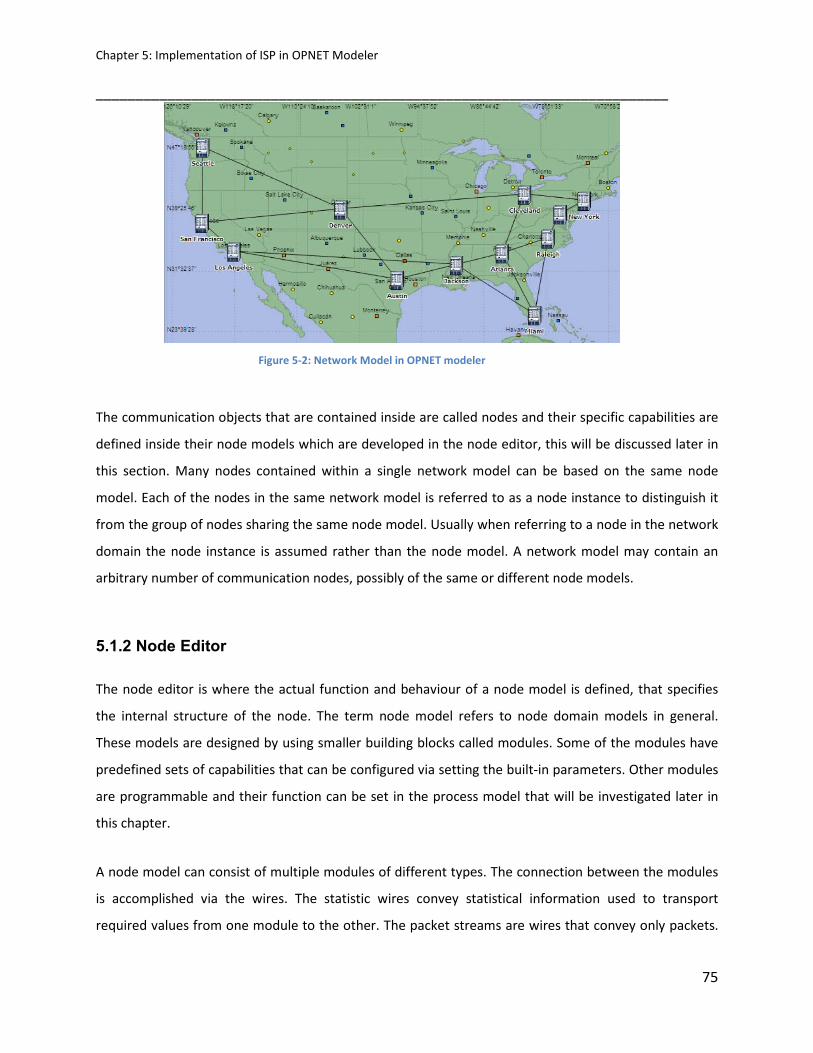
Chapter 5: Implementation of ISP in OPNET Modeler ________________________________________________________________________
75
Figure 5-2: Network Model in OPNET modeler
The communication objects that are contained inside are called nodes and their specific capabilities are
defined inside their node models which are developed in the node editor, this will be discussed later in
this section. Many nodes contained within a single network model can be based on the same node
model. Each of the nodes in the same network model is referred to as a node instance to distinguish it
from the group of nodes sharing the same node model. Usually when referring to a node in the network
domain the node instance is assumed rather than the node model. A network model may contain an
arbitrary number of communication nodes, possibly of the same or different node models.
5.1.2 Node Editor
The node editor is where the actual function and behaviour of a node model is defined, that specifies
the internal structure of the node. The term node model refers to node domain models in general.
These models are designed by using smaller building blocks called modules. Some of the modules have
predefined sets of capabilities that can be configured via setting the built-in parameters. Other modules
are programmable and their function can be set in the process model that will be investigated later in
this chapter.
A node model can consist of multiple modules of different types. The connection between the modules
is accomplished via the wires. The statistic wires convey statistical information used to transport
required values from one module to the other. The packet streams are wires that convey only packets.

Chapter 5: Implementation of ISP in OPNET Modeler ________________________________________________________________________
76
The transmitters and receivers together with the wires have a fixed function capability that contain
built-in parameters such as the data rate, the packet format that they can handle plus other set
parameters. In next Figure, a node model is given. The node model consists of different types of wires,
processors and has one pair of transmitter/receiver combination.
5.1.3 Process Editor
The design of the processor and queue modules is done in the “process model editor”.
This is the editor where the true algorithm of the processor is implemented. The algorithm is
accomplished by designing a finite state machine, where each state is programmed using C or C++ code.
Figure 5-3: Hierarchy of Various Domains
For a state to start executing the commands, an interrupt has to occur. Interrupts are events that are
directed at a process and that may require it to take some action. They may be generated by sources
external to a process (for example other modules), or by a process for itself. Interrupts usually
correspond to events such as messages arriving, timers expiring, resources being released or state
changes in other modules. In Figure 5-4, an example of a process model is presented. It represents a
simple process for a switching node. The transition between states is happening after an interrupt has
occurred. As shown for the figure 5-4, an interrupt can occur from different sources. A stream interrupt

Chapter 5: Implementation of ISP in OPNET Modeler ________________________________________________________________________
77
in the node editor drives a transition in the “idle” state which occurred from a packet arrival in the node.
A process interrupt occurs from the “idle” state when the packet arrived has its header obtained and
rewritten, that has as a consequence another occurrence of a transition that will forwarded the packet
into the transmitter in the node editor.
Figure 5-4: Example of Process model
There are two stages where the code is written on each state. These stages are known as “Enter
Executives” and the “Exit Executives“ and are illustrated in Figure 5-5. As shown in the figure 5-5, a state
can be either forced or unforced. When a state is unforced after executing the enter executives, the
process model becomes idle. What is meant by idle is that the control is sent to the simulation kernel.
The next time the process model is invoked by an interrupt, the execution begins again from the “exit
executives” of the state. When on the other hand a state is forced then after the enter execution it
proceeds to the exit stage and proceeds to the next state.

Chapter 5: Implementation of ISP in OPNET Modeler ________________________________________________________________________
78
Figure 5-5: Forced and unforced states in the process model editor
The changeover between states is called a transition and can be of two types. It can either be
conditional, where a condition must be satisfied in order to make the transition and the line connecting
two states becomes dashed. Or It can be unconditional where the transition will take place after all the
executions on the Source State have finished.
5.1.4 Packet/Link Editor
In the project editor all nodes are connected via links that can be generated through the link editor. In
the link editor attributes can be assigned such as the physical distance of these links, the data rate of the
transmission, and also the packet formats that can be used in the links. By setting the attributes
mentioned before the link models created provide the transmission and propagation delays in the
network being simulated.
The packet formats that are supported by the links can also be generated in OPNET using the packet
editor. Packet formats define the internal structure of packets as a set of fields. For each field, the
packet format specifies a unique name, a data type, a default value and a size in bits. A packet format
may contain one or more fields, represented graphically as a set of coloured rectangular boxes. The size
of the boxes is proportional to the number of bits specified in their size attribute.

Chapter 5: Implementation of ISP in OPNET Modeler ________________________________________________________________________
79
5.2 ISP Node Design
Simple WLAN Node is shown in Figure 5-6 as obtained from OPNET Modeler libraries.
The node model is subdivided into several layers, the application layer, Transport layer which is
presented by “tpal” and “tcp”,”udp” process modules, Network layer “ip”, the MAC layer, presented by
the process module “Wireless_lan_mac” and finally, the Physical layer, presented by a receiver block
“Wlan_port_rx0” and a transmission block “Wlan_port_tx0”. Between the Network layer and the MAC
layer, a process module appears that represents the interface connection between the two layers that is
called “arp”. The design of ISP node model has to contain a process model connected to the Network
layer and the MAC interface process module that contains all the operation and mechanism for ISP
protocol as explained before in Chapter 4. The ISP operation is adapted by updating some of the
operation design inside the Network layer. There is also the cross-layer interface appearing between the
Network layer and MAC layer.
In the next section, details of all the above changes in the designing of the simple wireless node
obtained by OPNET Modeler library to design the ISP node model will be presented.
Figure 5-6: ISP Node Model
5.2.1 ISP Node Figure 5-6 showed the node design model that was created for ISP.
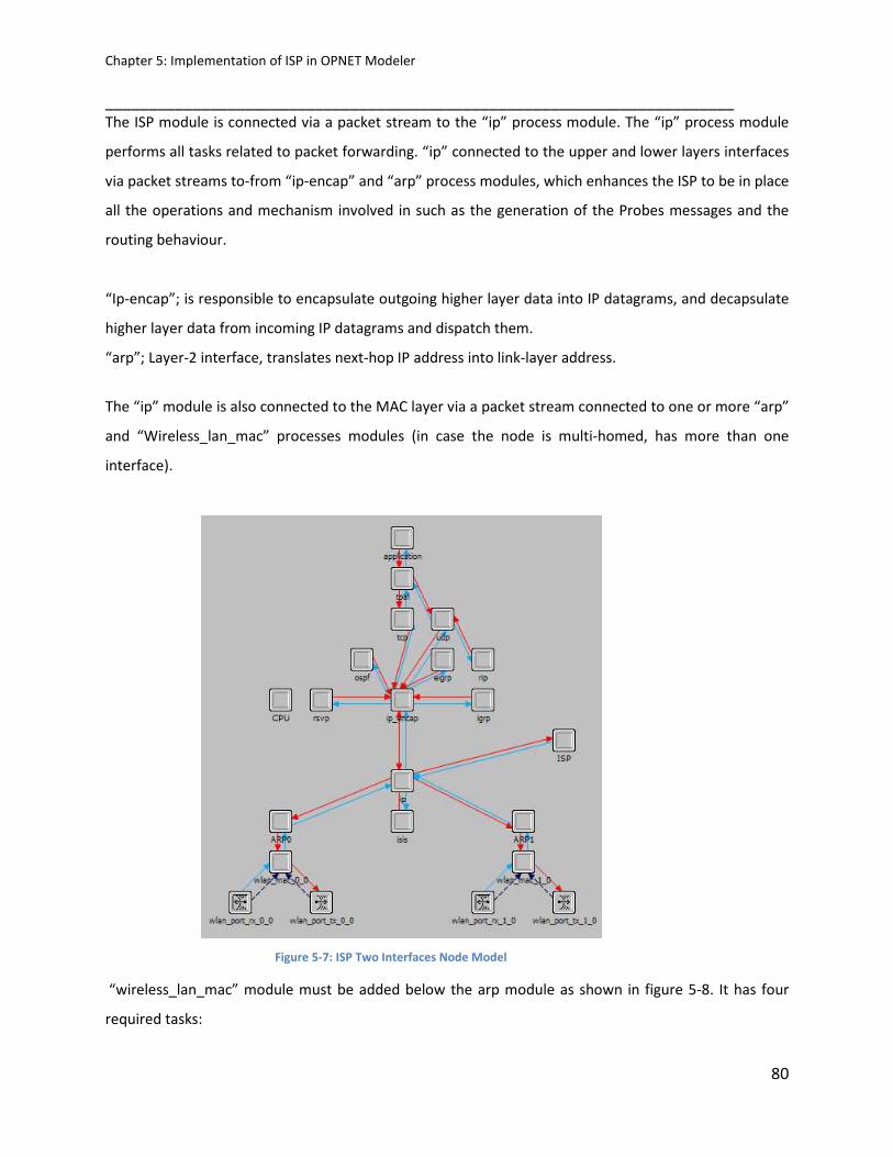
Chapter 5: Implementation of ISP in OPNET Modeler ________________________________________________________________________
80
The ISP module is connected via a packet stream to the “ip” process module. The “ip” process module
performs all tasks related to packet forwarding. “ip” connected to the upper and lower layers interfaces
via packet streams to-from “ip-encap” and “arp” process modules, which enhances the ISP to be in place
all the operations and mechanism involved in such as the generation of the Probes messages and the
routing behaviour.
“Ip-encap”; is responsible to encapsulate outgoing higher layer data into IP datagrams, and decapsulate
higher layer data from incoming IP datagrams and dispatch them.
“arp”; Layer-2 interface, translates next-hop IP address into link-layer address.
The “ip” module is also connected to the MAC layer via a packet stream connected to one or more “arp”
and “Wireless_lan_mac” processes modules (in case the node is multi-homed, has more than one
interface).
Figure 5-7: ISP Two Interfaces Node Model
“wireless_lan_mac” module must be added below the arp module as shown in figure 5-8. It has four
required tasks:

Chapter 5: Implementation of ISP in OPNET Modeler ________________________________________________________________________
81
1. Address assignment.
2. Process registry.
3. Handling packets from IP.
4. Handling packets from network.
Figure 5-8: IP Layer Process Models
The “Wireless_lan_mac” process module is involved in also setting different ways of sending
information (Broadcast) to the network and also generates the destination address of the packets
received from the above layer according to the selection made earlier on the way of sending
information to the network. The “wireless_lan_mac, arp” task is to accept data packets from the higher
layer in order to encapsulate the data into ISP frames, and to send these frames in to the destination
node. It offers efficient and fair sharing of bandwidth among all the nodes attached to the wireless LAN.
Collision avoidance and deference is handled by the individual node. Finally “wireless_lan_mac” process
module will forward the ISP wireless frame to the transmitter which will transmit the encapsulated
WLAN Frame either using Unicast or Broadcast depending on the information provided by “arp” process
module.
When the ISP wireless frame is received by the receiver it is forwarded to the MAC layer via a packet
stream connected to the “wireless_lan_mac” process module as mentioned earlier. The
“wireless_lan_mac” module will de-capsulate the WLAN frame sending it in the above layer by passing
through the “arp” process module and then to the routing “ip” layer. The routing “ip” layer checks the
packet format and initiates performing the routing in context with the protocol process module; more

Chapter 5: Implementation of ISP in OPNET Modeler ________________________________________________________________________
82
information of the operation of the routing will be discussed in details later in this section. The ISP
process module is also connected to the “ip”. The ISP gathers all statistical information that is needed
for correctly viewing and investigating the performance of the network.
According to Figure 5-7, there are many statistical wires used in ISP wireless node that responsible for
sending the information between the layers. Most essentially is a statistical wire that’s placed between
the ISP process module and the “ip” process module that is used to inform the network that a route
between a source node and a destination node is established. The “ISP” then sends the data packets for
the destination required via a packet stream connected to the “ip” process module. There are statistical
wires between the “wireless_lan_mac” process modules. The other two statistical wires are connected
to the transmitter sending the Utilisation to the MAC layer and also sending information as to when the
transmitter is busy. The last essential statistical wire is between the “wireless_lan_mac” process module
and “arp” process module. This statistical wire constantly updates the date rate and the bandwidth
information for that node’s interface to the routing protocol.
5.2.2 ISP Process Module
5.2.2.1 The Node Performance States
Once a node detects a failure, it starts the path exploration mechanism by changing its state from
Operational to Exploring. First, a Probe message is sent to test the current address pair, and if no
responses are obtained during a period of time called Retransmission Timer, the nodes start sending
Probes testing the rest of the available address pairs, using all possible source/destination address pairs
from all available wireless interfaces.
This allows resuming the communication through the initial path after short unavailability periods, due
to, for example light network congestion or local route reconfiguration. In this case ISP completes the
required handshake through the current path and returns to the Operational state without disrupting
the communication. However, if no response is obtained during another timer period called a

Chapter 5: Implementation of ISP in OPNET Modeler ________________________________________________________________________
83
Retransmission Timer period, thus requires finding alternative paths, defined by different combinations
of source and destination addresses. These paths are tested by sending Probe messages and waiting for
a response during a Retransmission timer period. Only one Probe is sent at a time. After sending the
maximum number of Probe messages which is assumed 4, an exponential back-off algorithm increases
the Retransmission Timer. When a Probe is received, this means that a valid unidirectional path has
been discovered for the incoming path. The node that has received the Probe message then changes its
state to Exploring-OK and uses Probe messages to continue exploring outgoing valid paths. This type of
Probe messages includes an indication of the valid incoming path. If the other node receives a Probe, it
can assume as valid the incoming path through which the packet was received, and it can obtain from
the payload of the Probe the valid outgoing path to be used. Then, the node changes its state to
Operational, and sends a Probe message in which it informs its peer about the validity of the path
through which it received the Probe message. A node that receives a Probe message changes its state to
Operational. It is worth to highlight that data is still being sent when the node is in the Exploring-OK
state using the source and destination addresses in use when the node was in the Operational state.
When the Operational state is reached again, the addresses in use are changed to the ones resulting
from the exploration process. Note that these rules may lead to different state and message sending
schedules: for example, one node can detect a failure and send a Probe exploring that arrives to its peer
before the peer detects a failure; or both nodes can detect a failure before receiving a Probe from the
other endpoint.
5.2.2.2 Routing States
Figure 5-9 presents the state machine diagram in OPNET modeller, that formalizes the behaviour
described above. The “Init” state is used for initialisation of some of the statistical variables. Moreover,
including some transitions that occurs only when a limited number of packets (either data, or Probes)
are lost, which could occur due to temporary path unavailability.

Chapter 5: Implementation of ISP in OPNET Modeler ________________________________________________________________________
84
Figure 5-9: ISP State Machine Diagram
The process after initialisation state moves to the “Operational” state and creates either a self interrupt
according to the Keep-alive timer period (The timers periods specified in the attributes stated in the
wireless LAN parameters in the project editor). Alternatively, when this period ends, another interrupt
occurs and the process transits to the “Exploring” state, since no keep-alive message is received from
the peer node during the suggested keep-alive period.

Chapter 5: Implementation of ISP in OPNET Modeler ________________________________________________________________________
85
Figure 5-10: Mobile Node Attributes
In the “Exploring” state, the process module starts sending the Probes messages using the current
address pair during the send-timer period. Since no Probe message is received from the peer node
during the suggested sending period. The state takes an action until the interrupt occurs that initiates
another transit to the “Exploring-Ok” state.
In the “Exploring-Ok” state the process module continue sending the Probes messages but by using a
new address pair, since no Probe message is received from the peer node during the suggested sending
period by using the recent used address pair. The state takes an action until the interrupt occurs that
initiates another transit either to the “Exploring” state in case the peer has not received the Probes
throughout the new address. Or transit to “Operational” state when there is no problem communicating
by using the new assigned address.

Chapter 5: Implementation of ISP in OPNET Modeler ________________________________________________________________________
86
This concurrent exploration is done after probing the current path. It could be thought that it could
reduce the failure recovery time by exploring the alternative paths also concurrently with the probing of
the current one when the ISP state changes from Operational to Exploring. While this could be true,
enforcing the preference to select other locators only if the Probe of the current path has failed at the
same time at which other paths are being concurrently probed may complicate slightly the state
machine of the ISP entities. For this kind of operation, ISP should store the addresses of the first
received Probe (if different from the current incoming path), and wait for a Probe for the current
incoming path until the Retransmission Timer expires.
If the Probe from the current incoming path arrives in time, the current path is preserved, and otherwise
the probing process continues with the information of the first received Probe.
1. Operational
The “Operational” state implies that:
(a) The sender has no problem communicating.
(b) The receiver also has no problem communicating.
Timer’s settings and transitions to other states:
1. Sending a packet in the Operational state, the node stops the Keep-alive timer if it was running
and starts the Send-timer if it was not running.
2. At a timeout on the Keep-alive timer, the node sends one last Keep-alive message. This can only
happen in the Operational state.
3. At the reception of a Keep-alive message in the Operational state, the node stops the Send
timer, if it was running. If the node is in the Exploring state it transitions to the Exploring-OK
state, sends a Probe message, and starts the Send timer.
4. At the reception of a Probe message with State set to Operational, the node stops the Send
timer if it was running, starts the Keep-alive timer if it was not yet running, and transitions to the
Operational state again.
This terminates the exploration process when both parties are happy and know that their peer is happy
as well.

Chapter 5: Implementation of ISP in OPNET Modeler ________________________________________________________________________
87
The exploration process has no effect on data communications until a new operational address pairs
have actually been confirmed. Prior to that, the packets continue to be sent to the previously used
addresses.
2. Exploring
The “Exploring” state implies that:
The sender has a problem communicating with the receiver; it has not seen any traffic from the receiver.
Timer’s settings and transitions to other states:
1. Upon a timeout on the Send timer, the node enters the Exploring state and sends a Probe
message. While in the Exploring state, the node keeps retransmitting its Probe messages to
different (or same) addresses.
2. If the node is in the Exploring state and not receiving a probe back, it then enforced to
transitions to the Exploring -OK state, sends a Probe message, and starts the Send timer.
3. It fills the fields for the corresponding Probe source address, Probe destination address, number
of Probes and their type. While in the Exploring state the node keeps retransmitting its Probe
messages to different (or same) addresses.
3. Exploring-OK
Exploring-Ok implies that the sender believes it has no problem communicating, i.e., it at least sees
packets from the receiver, but that the receiver either has a problem or has not yet confirmed to the
sender that the problem has been solved.
Timer’s settings and transitions to other states:
1. When receiving a Probe with state set to Exploring, the node enters the Exploring -OK state,
sends a Probe stops the Keep-alive timer if it was running, and restarts the Send timer. As in

Chapter 5: Implementation of ISP in OPNET Modeler ________________________________________________________________________
88
Exploring state. A similar process is employed in the Exploring-Ok state, except that upon such
retransmission the Send timer is started if it was not running already
2. Upon the reception of a Probe message with State set to Exploring-Ok, the node sends a Probe
message, restarts the Send timer, stops the Keep-alive timer if it was running
3. Transitions to the Operational state.
In the Exploring -Ok state; the new current address pair is chosen for the connection, based on the
reports of received probes in the message that we just received. If no received probes have been
reported from the new address, the current address pair is unchanged.
5.2.2.3 Wireless –LAN- MAC-Interface (MAC layer)
The IEEE 802.11 MAC layer provides functionality to allow reliable data delivery for the upper layers over
the wireless physical (PHY) media. The data delivery itself is based on an asynchronous, best-effort,
connectionless delivery of MAC layer data.
There is no guarantee that the frames will be delivered successfully. The IEEE802.11 MAC provides a
controlled access method to the shared wireless media called Carrier-Sense Multiple Access with
Collision Avoidance (CSMA/CA). CSMA/CA is similar to the collision detection access method deployed
by 802.3 Ethernet LANs.
The other function of the IEEE802.11 MAC, is to protect the data being delivered by providing security
and privacy services. Security is provided by the authentication services and by Wireless Equivalent
Privacy (WEP), which is an encryption service for data delivered on the WLAN.
5.2.2.4 WLAN- Transmission (Physical layer)
The IEEE802.11 physical layer (PHY) is the interface between the MAC and the wireless media where
frames are transmitted and received. The PHY provides three functions. First, the PHY provides an
interface to exchange frames with the upper MAC layer for transmission and reception of data.
Secondly, the PHY uses signal carrier and spread spectrum modulation to transmit data frames over the

Chapter 5: Implementation of ISP in OPNET Modeler ________________________________________________________________________
89
media. Thirdly, the PHY provides a carrier sense indication back to the MAC to verify activity on the
media [2].
IEEE802.11 provides three different PHY definitions: Both Frequency Hopping Spread Spectrum (FHSS)
and Direct Sequence Spread Spectrum (DSSS) support 1 and 2 Mbps data rates. An extension to the
IEEE802.11 architecture (IEEE802.11a) defines different multiplexing techniques that can achieve data
rates up to 54 Mbps. Another extension to the standard (IEEE802.11b) defines 11 Mbps and 5.5 Mbps
data rates (in addition to the 1 and 2Mbps rates) utilizing an extension to DSSS called High Rate DSSS
(HR/DSSS). IEEE802.11b also defines a rate shifting technique where 11 Mbps networks may fall back to
5.5 Mbps, 2 Mbps, or 1 Mps under noisy conditions or to inter-operate with legacy IEEE802.11 PHY
layers [3].
Figure 5-11 shows the attributes for wireless transmitter. The attributes which are being used in the
simulation will be described in detail below.
The “data rate” attribute is the rate at which information may be forwarded over the data transmission
channel. The “bandwidth” attribute specifies the bandwidth of the channel. The “min frequency”
attribute specifies the base frequency of the channel.

Chapter 5: Implementation of ISP in OPNET Modeler ________________________________________________________________________
90
Figure 5-11: Mobile Node's Transmitter Attributes
Furthermore, information on the exact operation of each of the models’ attributes used, can be found in
the chapter of wireless LAN model user guide in OPNET Modeler documentation.
5.3 Testing the Module
In this section a description of the way that a ISP model can be setup in OPNET
Modeler using our proposed model will be presented. Furthermore, some testing that was done in order
to verify the correct operation of new proposed model will be given with the help of a simulating
scenario of the proposed algorithm. When presenting this scenario, the full operation of the ISP
algorithm (explained in Chapter 4) will be described, using simulation results and tables created in
OPNET Modeler.

Chapter 5: Implementation of ISP in OPNET Modeler ________________________________________________________________________
91
5.3.1 ISP Network Design After the creation of the project in OPNET Modeler, the area of the network being simulated should be
defined to be of a reasonable size as in our example the area covered by 1000X1000 (meters), the nodes
are placed within the specified area as shown below. Examples of attributes values of each node are
shown. The values of the required attributes will be discussed next.
Simulation network model is consisting of the scenario shown in figure 5-12. This scenario most
commonly used in any wireless environment with either a low or high load. As an example can be at
home, office, campus and airport, etc.
The mobile node (MN) has two wireless interfaces, each interface has a specific Global address
(publically routable addresses used with a WLAN to reach an interface from anywhere on the Internet)
[4]. MN communicates with its peer, the correspondent node (CN) through IF1 to AP1 (WLAN1 access
point) and HA1 (WLAN1 Home Agent) connected the wireless network to IP cloud which is used here to
represent the internet backbone connectivity.

Chapter 5: Implementation of ISP in OPNET Modeler ________________________________________________________________________
92
Figure 5-12: ISP Network in OPNET Modeler
5.3.2 Mobile Node (MN) Attributes
The MN attributes are shown in figure 5-13. First, two different IPv6 global addresses are assigned to
each MN’s wireless interface.
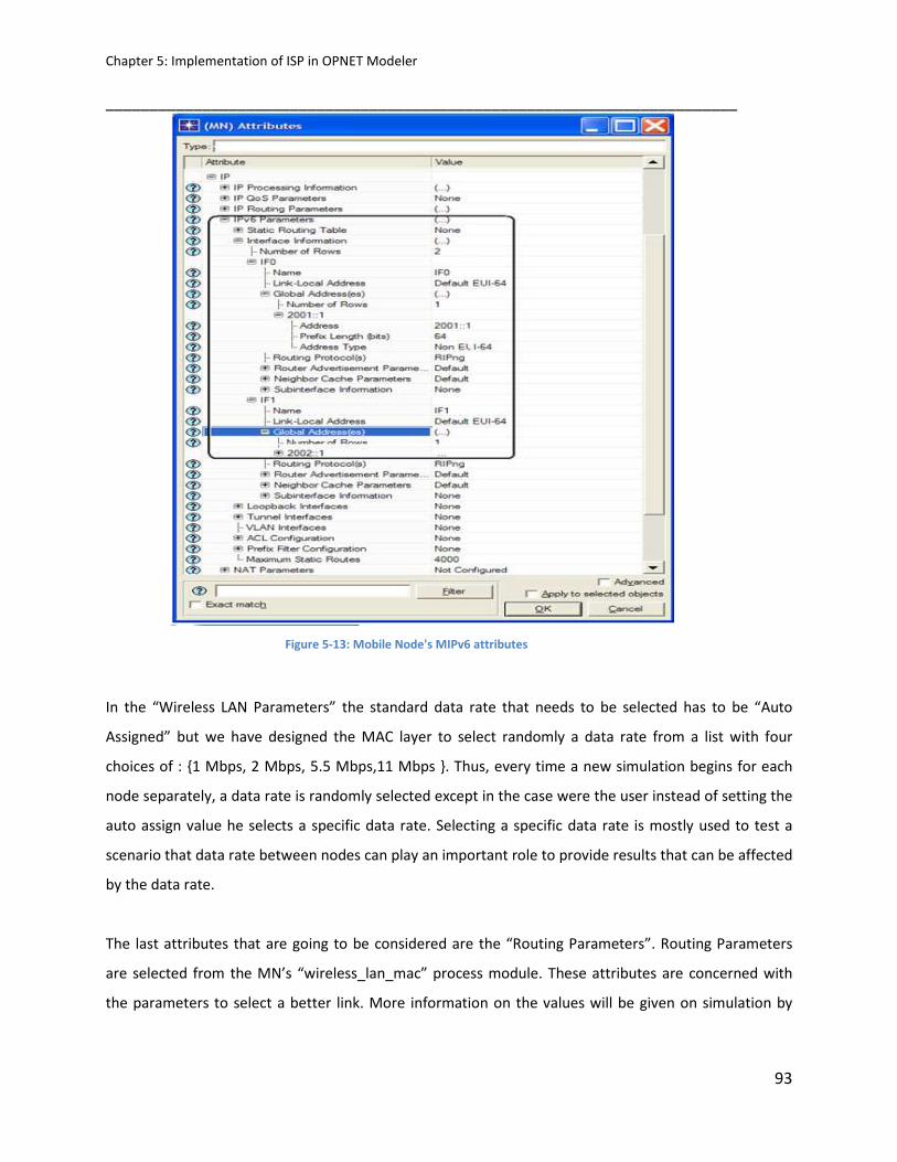
Chapter 5: Implementation of ISP in OPNET Modeler ________________________________________________________________________
93
Figure 5-13: Mobile Node's MIPv6 attributes
In the “Wireless LAN Parameters” the standard data rate that needs to be selected has to be “Auto
Assigned” but we have designed the MAC layer to select randomly a data rate from a list with four
choices of : {1 Mbps, 2 Mbps, 5.5 Mbps,11 Mbps }. Thus, every time a new simulation begins for each
node separately, a data rate is randomly selected except in the case were the user instead of setting the
auto assign value he selects a specific data rate. Selecting a specific data rate is mostly used to test a
scenario that data rate between nodes can play an important role to provide results that can be affected
by the data rate.
The last attributes that are going to be considered are the “Routing Parameters”. Routing Parameters
are selected from the MN’s “wireless_lan_mac” process module. These attributes are concerned with
the parameters to select a better link. More information on the values will be given on simulation by
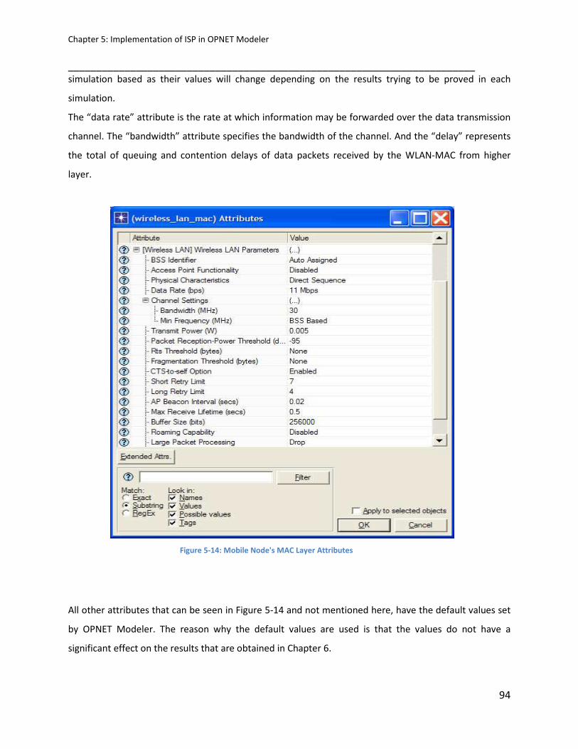
Chapter 5: Implementation of ISP in OPNET Modeler ________________________________________________________________________
94
simulation based as their values will change depending on the results trying to be proved in each
simulation.
The “data rate” attribute is the rate at which information may be forwarded over the data transmission
channel. The “bandwidth” attribute specifies the bandwidth of the channel. And the “delay” represents
the total of queuing and contention delays of data packets received by the WLAN-MAC from higher
layer.
Figure 5-14: Mobile Node's MAC Layer Attributes
All other attributes that can be seen in Figure 5-14 and not mentioned here, have the default values set
by OPNET Modeler. The reason why the default values are used is that the values do not have a
significant effect on the results that are obtained in Chapter 6.

Chapter 5: Implementation of ISP in OPNET Modeler ________________________________________________________________________
95
5.3.3 ISP Route Technique
This section presents the ISP Routing protocol operation and testing as it appears in OPNET Modeler. To
help in the understanding of ISP routing operation a simple scenario will be tested as seen in Figure 5-
15. The scenario is a specific source to specific destination via two paths. The source node is the MN
connected via two interfaces to the CN destination node (each interface has a global IP address 2001::1-
4). There are two routes available in this scenario; the first route will be (MN-WLAN1-CN). The other
route will be (MN-WLAN2-CN). The WLAN1 and WLAN2 are IP Routers which have specific attributes
under IP Routing Protocols scheduling. These attributes are used to configure parameters for the routing
protocols in the network.
Figure 5-15: ISP Route Test Scenario
The main difference between the two paths is the available data rate. From Table 4-2, it can be seen
that the second has a much higher available bandwidth (data rate) from the first. The one-way delay to
the CN from each WLAN is varied: that from WLAN1 is set to 35 ms and that from WLAN2 is set to 16ms.

Chapter 5: Implementation of ISP in OPNET Modeler ________________________________________________________________________
96
Table 5-2: Paths Various Route Parameters
The scenario that is being investigated has the Bandwidth-limit (data rate) equal to 7.0 and the Delay-
limit equal to 20ms. This has been setup in such a way as to have the path selection being dependent on
data rate (bandwidth) and the delay.
To explain how the routing is performed in the example given in figure 5-15, we divided the ISP routing
protocol into two phases that covers all the routing operation. The first phase is the interface switching
phase where the source tries to find a better link to the destination (this will take place in MAC, IP
layers). The second phase, called the Route phase (which is done in the IP layer) where the ISP has the
routing operations done.
1. Interface Switching Algorithm Phase
As the condition of a wireless link is degraded, the Bandwidth value decreases and the Delay Value
increases, the sender sends data packets to the receiver over two WLANs interfaces in order to prevent
packet loss. In the case of moving to another WLAN without Two-path transmission, the communication
quality might be degraded due to not knowing the condition of the next wireless link in advance.
Therefore, the ISP should investigate the condition of both wireless links (interfaces) using Two-path
transmission when the Delay Value is growing. Then, when the ISP discovers a WLAN that has a wireless
link of good condition, the transmission returns to One-path transmission through this WLAN.
1. The MN first interface (IF1) fills the field of the Bandwidth value whenever an ACK frame is
received or the Bandwidth value reaches the Bandwidth-limit.
2. In each entry the accumulated “Bandwidth” and “Delay” values of the path until the node which
has received the Probe are also stored.
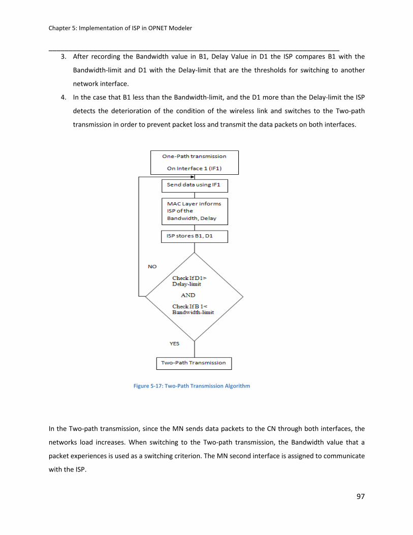
Chapter 5: Implementation of ISP in OPNET Modeler ________________________________________________________________________
97
3. After recording the Bandwidth value in B1, Delay Value in D1 the ISP compares B1 with the
Bandwidth-limit and D1 with the Delay-limit that are the thresholds for switching to another
network interface.
4. In the case that B1 less than the Bandwidth-limit, and the D1 more than the Delay-limit the ISP
detects the deterioration of the condition of the wireless link and switches to the Two-path
transmission in order to prevent packet loss and transmit the data packets on both interfaces.
Figure 5-17: Two-Path Transmission Algorithm
In the Two-path transmission, since the MN sends data packets to the CN through both interfaces, the
networks load increases. When switching to the Two-path transmission, the Bandwidth value that a
packet experiences is used as a switching criterion. The MN second interface is assigned to communicate
with the ISP.

Chapter 5: Implementation of ISP in OPNET Modeler ________________________________________________________________________
98
2. Routing Mechanism Phase
If data packets from a node do not arrive to the peer node during a calculated time, it is assumed that
the selected path between source and destination is lost or broken. It starts the path exploration
mechanism by changing its state from Operational to Exploring as mentioned earlier. First, a Probe
message is sent to test the current address pair, and if no responses are obtained during a period called
Retransmission Timer, the nodes start sending Probes testing the rest of the available address pairs,
using all possible source/destination address pairs from all available wireless interfaces.
The route discovery process begins when the node needs to find a route to the destination by
broadcasting Probes. The Probing packet broadcasted has seven fields as shown in Figure 5-18. These
fields filled except “Route Parameters”, such as “Source and destination Addresses”, “Probes sent and
received with their type” with the state.
The wireless node will create a container for the new packet. The new packet is consisting of: IPv6
Header + ISP Header (Probe message header)
ISP Header: is the header is used to carry upper layers packets (ULP) where the receiver must replace
the content of the source and/or destination fields in the IPv6 header before passing the packet to the
ULP.
It will be directed to the “ip” process module to encapsulate it into an IP packet, and then sent to the
node memory to be stored until the route process has finished and so it will be ready to be sent.
Figure 5-18: Probe Message Format
When a node receives a Probe packet will read its fields and update its “Route Parameters” fields. The
way that a table is filled will now be explained with the help of our example.

Chapter 5: Implementation of ISP in OPNET Modeler ________________________________________________________________________
99
The entries in the tables are created when a Probe message is received for the first time from a node.
The node will create an entry with identification supplied by the fields of the Probe. The time at which
the Probe was received is also stored in the memory. In each entry the accumulated “Route Parameters”
of the path until the node which has received the Probe is also stored.
The reason is to find the best path with the best “Route Parameters” values. There are the two best
paths stored for each unique address pair. The primary path which is not the best path found, and a
secondary path that may be required if there is a link or a node failure somewhere in the current path
during transmission of the data.
A node might receive multiple Probes for the same Address pair; in this case it will select the pair that
provides the best Route Parameters for that path until now. In Table 4-2 it can be seen that there are
two paths from MN to CN. The second Path has better Route Parameters than first Path as the second
Path has a higher available bandwidth and lower delay than the first Path.
In our example, a single packet was sent from the source to our destination. Finally in Figure 5-19, we
can see the received packets from in the new path received when we have an increased traffic flow.

Chapter 5: Implementation of ISP in OPNET Modeler ________________________________________________________________________
100
Figure 5-19: Packets received at the destination
The testing for alternative route can be shown by having the mobile node changing its current interface
for an interval of approximately 20 seconds starting at 25 seconds of the simulation time.
By looking at the throughput of the mobile node, figure 5-20, it can be clearly seen that it receives no
data traffic at the time it starts moving away from the primary path. When MN starts send traffic via the
second path, it starts again receiving data information. Also It can be seen that it only Probe messages
for the whole duration of the simulation except at the time it becomes active at around 37 seconds.
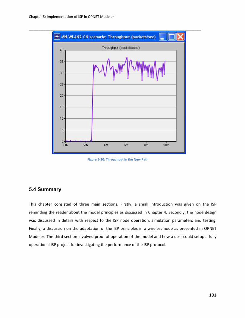
Chapter 5: Implementation of ISP in OPNET Modeler ________________________________________________________________________
101
Figure 5-20: Throughput in the New Path
5.4 Summary
This chapter consisted of three main sections. Firstly, a small introduction was given on the ISP
reminding the reader about the model principles as discussed in Chapter 4. Secondly, the node design
was discussed in details with respect to the ISP node operation, simulation parameters and testing.
Finally, a discussion on the adaptation of the ISP principles in a wireless node as presented in OPNET
Modeler. The third section involved proof of operation of the model and how a user could setup a fully
operational ISP project for investigating the performance of the ISP protocol.
Chapter 5: Implementation of ISP in OPNET Modeler ________________________________________________________________________
102
5.5 References
[1] OPNET Modeler, OPNET Technologies Incorporation. www.opnet.com
[2] S. R. Das, C. E. Perkins et E. M. Royer, “Performance Comparison of Two On-demand Routing
Protocols for Ad Hoc Networks”, In IEEE Personal Communications, vol. 8, no. 1, pp. 16 28, Février
2001.
[3] S R Chaudhry, A N Al-Khwildi, Y K Casey , H Aldelou, H S Al-Raweshidy “A
System Performance Criteria of On-Demand Routing in Mobile Ad Hoc Networks”, Wireless and
Mobile Computing, Networking and Communications, IEEE WiMob2005,August 2005 Montreal,
Canada.
[4] Iljitsch van Beijnum, “IPv6 Internals”, The Internet Protocol Journal - Volume 9, Number3.Available
on: http://www.cisco.com/web/about/ac123/ac147/Archived
_issues/ipj_9-3/ipv6_internals.html

Chapter 6: Simulation results & scenarios of ISP ________________________________________________________________________
6
5 Chapter 6103
SIMULATION RESULTS & SCENARIOS of ISP
6.1 Introduction
This chapter presents a comprehensive study of ISP protocol using the simulation software OPNET
version 14.0. As far as know, there are two different ways to model and evaluate wireless LANs: Real
time scenario and the simulation environment. Due to the dynamic nature of Multi-homed network, it is
difficult and time consuming to analyse all scenarios in real time on a wireless test bed. Likewise, Multi-
homing is still a live research subject where most of scenarios and research challenges are yet to be
addressed. For instance, measuring the performance of a particular multi-homing protocol, it is easier to
formulate scenarios comprising hundreds of wireless stations. However, for doing the same in real time,
it is unaffordable by an individual researcher. Therefore, the only practical option is to use a credible
simulation software for testing various parameters while keeping various scenarios as close to the real
systems as possible.
This chapter is divided in three sections; first section explains the simulation environment in details such
as the type of the networks, network size, and type of the traffic that used to send from the source to
the destination. Furthermore, in this section will present the evaluation parameters that were used and
measured in the different routing protocols. The second section will present the ISP results that show
the adaptability of the protocol and shows the “Route Parameters” for different scenario. The third
section shows full comparison for ISP with three different well-known multi-homing routing protocols
such as MIPv6 and Shim6. The comparison will cover most of the real life scenario such as the different
type of the networks (according to the coverage/size). Thus, the performance of the protocol is analysed
in varying node density, mobility patterns (high/low mobility) and varying types of application-generated
traffic (delay sensitive real time traffic and non real time traffic).

Chapter 6: Simulation results & scenarios of ISP ________________________________________________________________________
104
6.2 Simulation Environment
We conducted extensive simulations to evaluate the performance of ISP and compare it with MIPv6,
Shim6. The simulations were implemented on OPNET 14.0. The nodes used in the simulations were
wireless nodes based on IEEE standard 802.11 with different type of the data rate such as 11Mbps,
5.5Mbps. The nominal packet size used by the nodes was kept to 1024 Bytes. The network area was
1000mx1000m. The simulation running time varies depending on when the simulation data for each of
the scenarios becomes saturated, in order to correctly understand and explain the results.
6.2.1 Evaluation Parameters
The performance of ISP is evaluated by measuring four parameters, routing discovery time, network
load, media access delay, and data drop. In this section, the comparison of ISP with well-known
protocols will be presented. First, a detailed analysis will be given on how the data were gathered from
what simulations and how were they analysed.
• Routing Discovery Time: The time for the routing path to be established, from the source node
to the destination node.
• Network Load: Represents the total load (in bits/sec) submitted to wireless LAN layers by all
other higher layers in all WLAN nodes of the network. This statistic does not include the bits of
the higher layer packets that are dropped by WLAN MACs upon arrival and not considered for
transmission.
• Media Access Delay: Represents the global statistic for the total of queue and contention delays
of data packets received by all WLAN MACs in the network from higher layer. For each packet,
the delay is recorded when the packet is sent to the physical layer for the first time. Hence, it
also includes the period for the successful RTS/CTS exchange, if this exchange is used for that
packet.
• Data Dropped: The total size of higher layer data packets dropped by all the

Chapter 6: Simulation results & scenarios of ISP ________________________________________________________________________
105
WLAN MACs in the network due to:
a) The overflow of higher layer buffer, or
b) Failure of all retransmissions until retry limit.
6.3 Simulation Results
6.3.1 Role of ISP Route Parameters
In this section, we are going to describe the role and the effects of the “Route Parameters”.
6.3.1.1 Route Discovery Time
To accomplish this first we are going to look at a small network (network with small coverage area) and
secondly at a larger network and see the effects of the different parameters applied at the nodes. We
are investigating three scenarios, the first one with “B1” only in operation which represents the
bandwidth (data rate), with “D1” only in operation which represents the delay, and finally a scenario
called “The Standard” with all parameters operating equally. It has to be noted that data rate is selected
randomly in each path.
Figure 6-1, it can see the route discovery time. Routes can be discovered faster in small network with
the D1 applied only. This is expected as it tries to find the fastest route.
The slowest route discovery time can be seen by B1. This of course depends on how the network has
been setup. As the network that is now being used for our investigation of route parameters has paths
with different data rates.

Chapter 6: Simulation results & scenarios of ISP ________________________________________________________________________
106
Figure 6-1: Route Discover Time in Small Network
In Figure 6-2, route discovery can be seen for a larger network. Here the B1 scenario is the one with the
fastest route discovery time although it doesn’t look to find the fastest route. This has to do with the
effect of a large network which now the routes that need to be discovered can have nodes that have a
low data rate that will increase the delay of transmission. The delay in D1 itself is a calculation of a
shortest path rather than true delay but usually the shortest path will give the shortest delay for small to
medium networks. The standard scenario can be seen not to give the best results, so far, for route
discovery time as the selection has to be according to all parameters.

Chapter 6: Simulation results & scenarios of ISP ________________________________________________________________________
107
Figure 6-2: Route Discover Time in Large Network
6.3.1.2 Network Load
The simulation was performed both with varied load of VoIP streams in the network. The average load is
ranging from 45% to 75%. This setup is necessary to identify the requirements on the transport for
events delivery between network layers components.
The response of light load (ranging to 45%) is almost unchanged having low rate of retransmitted
packets. Therefore, we register a lower probability of loosing message as a better case scenario. In high
load setup (ranging to 75%), there is a higher probability of loosing messages; thus, message
retransmission rate will be higher. This has been proved by checking the respective retransmission
average time on message in both conditions of load. The results confirmed that the retransmission time
increases as the network load increases. We argue that this is an expected result being lower than the
probability of generating events in saturation conditions. Therefore, when looking at the network load
for small networks it can be seen that D1 produces a far less load than all other scenarios as shown in
figure 6-3, this can be explained, as the route found is the shortest path.

Chapter 6: Simulation results & scenarios of ISP ________________________________________________________________________
108
Figure 6-3: Network Load in Small Network
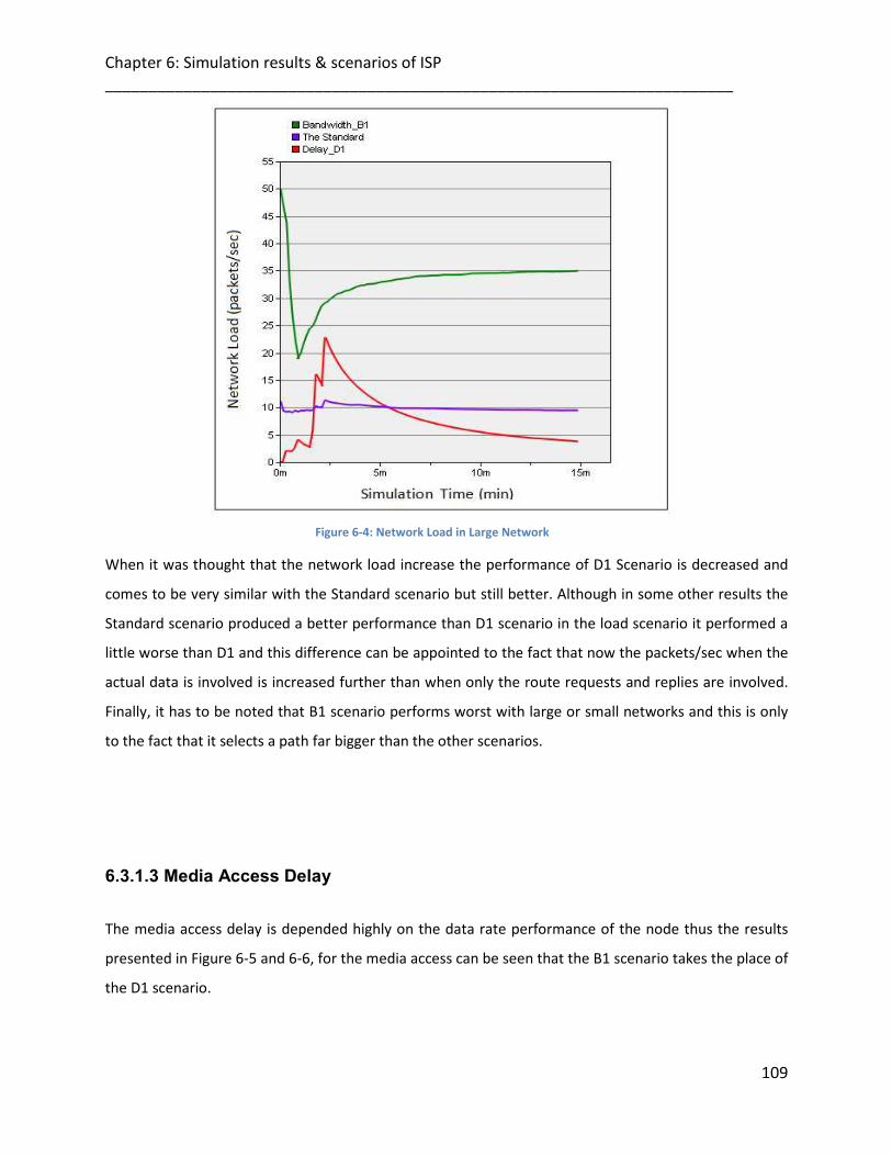
Chapter 6: Simulation results & scenarios of ISP ________________________________________________________________________
109
Figure 6-4: Network Load in Large Network
When it was thought that the network load increase the performance of D1 Scenario is decreased and
comes to be very similar with the Standard scenario but still better. Although in some other results the
Standard scenario produced a better performance than D1 scenario in the load scenario it performed a
little worse than D1 and this difference can be appointed to the fact that now the packets/sec when the
actual data is involved is increased further than when only the route requests and replies are involved.
Finally, it has to be noted that B1 scenario performs worst with large or small networks and this is only
to the fact that it selects a path far bigger than the other scenarios.
6.3.1.3 Media Access Delay
The media access delay is depended highly on the data rate performance of the node thus the results
presented in Figure 6-5 and 6-6, for the media access can be seen that the B1 scenario takes the place of
the D1 scenario.
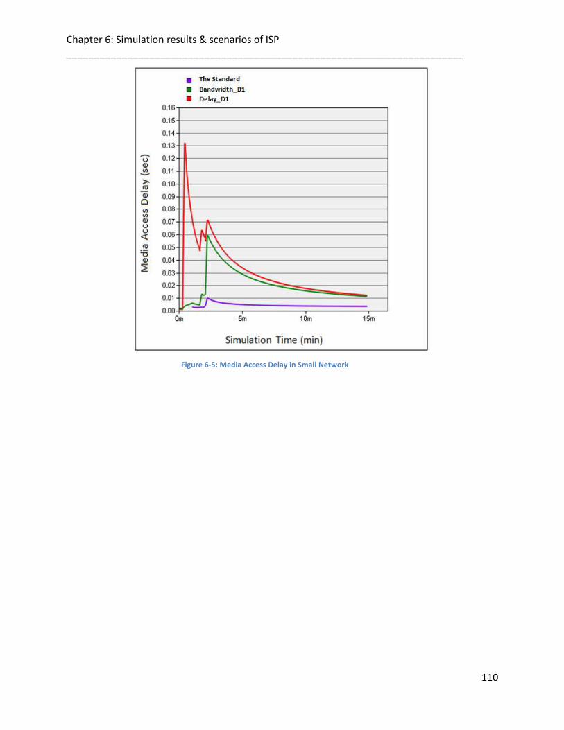
Chapter 6: Simulation results & scenarios of ISP ________________________________________________________________________
110
Figure 6-5: Media Access Delay in Small Network

Chapter 6: Simulation results & scenarios of ISP ________________________________________________________________________
111
Figure 6-6: Media Access Delay in Large Network
The significant point in these results has to be the performance of the Standard scenario in large
networks, where it outperforms by far all other scenarios even the B1. This can be credited to the fact
that the Standard scenario is a compromise between D1 and B1 scenarios, thus finding routes with high
data rates and with the shortest path possible.
6.3.1.4 Data Dropped
The lowest data dropped can be seen by the B1 scenario in small and large networks as present in Figure
6-7 and 6-8. The reason behind this is that for a data to be dropped it has to come to a node that is
processing another request at the particular time. This happens more frequently when data rate is low
thus in D1 scenarios where the selection of routes is based on the shortest route and the nodes that are
involved in this route might have a bad data rate thus increasing the possibility of data dropping.

Chapter 6: Simulation results & scenarios of ISP ________________________________________________________________________
112
Figure 6-7: Data Dropped in Small Network
When using the B1 scenarios in the large network though where it is based on bandwidth the data
dropped comes to a minimum. The Standard scenario produces a good result, which is between the D1
and B1 scenarios.

Chapter 6: Simulation results & scenarios of ISP ________________________________________________________________________
113
Figure 6-8: Data Dropped in Large Network
As a final, though it can be seen that the parameters used by ISP can produce different effects
depending on the parameter used. This has an effect on the ISP protocol to become very
versatile/adaptable. Thus, when a scenario comes where data dropped is crucial for the operation of the
network the B1 parameter can be used to adapt to this scenario. When route discovery is crucial the D1
parameter comes into consideration. The different scenario parameters though can be used also
individually in each node. So each node depending on its capabilities and its way of operation it can be
dependent in different parameters thus producing scientifically better result for ISP than any other
protocol around.
This investigation will now be considered. The Standard scenario will now be used for comparing the ISP
protocol with all other well-known protocols for multi-homing networks.
6.3.2 Comparison Scenarios
There are important performances metrics evaluated in all three multi-homing routing protocols (ISP,
IPv6, and Shim6) simultaneously with different network size.
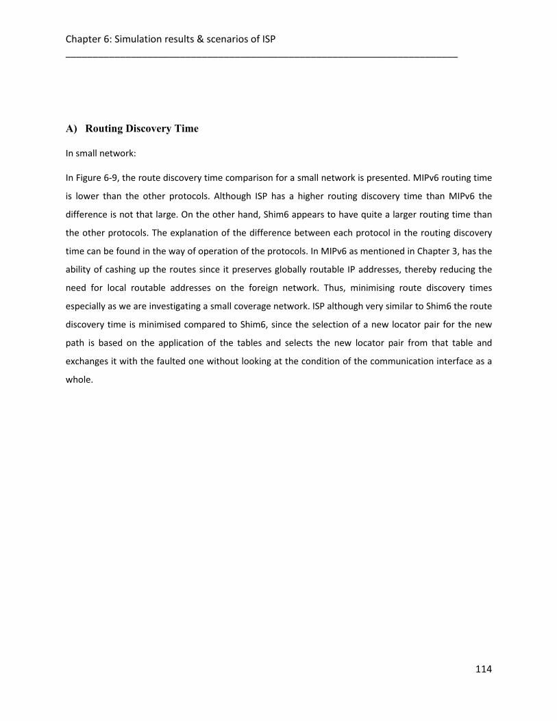
Chapter 6: Simulation results & scenarios of ISP ________________________________________________________________________
114
A) Routing Discovery Time In small network: In Figure 6-9, the route discovery time comparison for a small network is presented. MIPv6 routing time
is lower than the other protocols. Although ISP has a higher routing discovery time than MIPv6 the
difference is not that large. On the other hand, Shim6 appears to have quite a larger routing time than
the other protocols. The explanation of the difference between each protocol in the routing discovery
time can be found in the way of operation of the protocols. In MIPv6 as mentioned in Chapter 3, has the
ability of cashing up the routes since it preserves globally routable IP addresses, thereby reducing the
need for local routable addresses on the foreign network. Thus, minimising route discovery times
especially as we are investigating a small coverage network. ISP although very similar to Shim6 the route
discovery time is minimised compared to Shim6, since the selection of a new locator pair for the new
path is based on the application of the tables and selects the new locator pair from that table and
exchanges it with the faulted one without looking at the condition of the communication interface as a
whole.

Chapter 6: Simulation results & scenarios of ISP ________________________________________________________________________
115
Figure 6-9: Route Discovery Time in Small Network
In large network: Figure 6-10, shows routing discovery time for the protocols, the increase of the network size had little
effect in the comparison of the route discovery time to MIPv6 and Shim6 if any at all. There was though
a slight increase of routing discovery time for ISP. This can be credited to the fact that ISP finds now
paths that are optimised further according to route parameters. This in effect has the paths selected
having more distance for each route than MIPv6 and Shim6 where the route selected in these protocols
is done by finding the shortest path.

Chapter 6: Simulation results & scenarios of ISP ________________________________________________________________________
116
Figure 6-10: Route Discovery Time in Large Network
B) Network Load In small network: Figure 6-11 shows the network load for all protocols. ISP provides lower network load from all the
protocols as it will only sent Probe messages when trying to find a route. In Shim6, there is a possibility
the source address cache is not used for the packets retransmission , the IP layer sends the same
packets as different source address are available, each one with a different address, which causes an
additional load imposed by duplicated packets. MIPv6 has a higher load network than Shim6, although it
sends a small number of binding messages to establish a route it has to send information about the
whole route, and since MN moves frequently, the number of binding messages increases proportionally
adds a significant extra load to network.

Chapter 6: Simulation results & scenarios of ISP ________________________________________________________________________
117
Figure 6-11: Network Load in Small Network
In large network: As the network coverage in our simulation is being increased it can be seen from
Figure 6-12, there seems to be no significant change in the comparison of the performance of all
protocols for the network load. ISP/Shim6 seems to have a low load and MIPv6 a little higher again
because of the binding messages increases as mentioned before for the small network simulation.

Chapter 6: Simulation results & scenarios of ISP ________________________________________________________________________
118
Figure 6-12: Network Load in Large Network
It’s obvious that ISP always has lower network load comparing to the other protocols because of the
efficient and fast mechanism which makes the network very light and it is obvious from the curves that
seen before as well. Also, Shim6 behaved quite stable like ISP but has more of the network load
because of the number of the cache its increased but still better then MIPv6 at this point because with
MIPv6, many broadcasting messages and acknowledgment.
C) Media Access Delay In small network: The next parameter being investigated is the media access delay of the data packets.
In Shim6 and ISP a low media access delay can be seen of approximately 0.0008 and 0.0003 respectively.
This low value can be explained because of the route discovery mechanism which is performed that it is
trying to find the optimum path available according to the smallest delay.
In ISP though a slight increase in media access delay can be observed because ISP for these simulations
has its route parameters based on all parameters delay, bandwidth on each node. For MIPv6 protocol its
media access delay is high because they operate with routing tables and binding messages at the home

Chapter 6: Simulation results & scenarios of ISP ________________________________________________________________________
119
agent node in order to find the routing from source to destination this will create a queue at the buffers
of the MAC layer which will in effect increase the media access delay because of the delay occurred
while queuing in each node, as shown in Figure 6-13.
Figure 6-13: Media Access Delay in Small Network
In large network:
As it is obvious from Figure 6-14, again as with larger network Shim6 and ISP have the lower media
access delay as route discovery mechanism is performed trying to find the optimum path available.
Shim6 and MIPv6 had an increase of 2%, 2%, and 2.5% respectively. ISP though had an increase of only
1%. This can be given credit to the optimisation from the route parameters.

Chapter 6: Simulation results & scenarios of ISP ________________________________________________________________________
120
Figure 6-14: Media Access Delay in Large Network
D) Data Dropped In small network:
In Figure 6-15, all protocols have approximately the same data dropped with slightly better performance
of Shim6 and ISP. MIPv6 has knowledge of the network status so it will find a route that can
accommodate the data being sent. The ISP protocol although it does not have knowledge of the network
status it still can find the best route because of route parameters. The Shim6 protocol does not have
knowledge of the network status so it would expect to become overwhelmed and drop a lot more data
than any other protocol. But this does not happen as the results are for a small network.

Chapter 6: Simulation results & scenarios of ISP ________________________________________________________________________
121
Figure 6-15: Data Dropped in Small Network
In large network:
Figure 6-16, with large network in the simulation it can be seen that the Shim6 protocol has increased its
data dropped slightly as it has no knowledge of the network status and so some data because of the
increasing amount of data start moving to nodes where they do not have available bandwidth.
For the MIPv6 protocol a similar data dropped can be seen from Shim6 because of its adaptive nature,
i.e. that it knows the network status by the broadcasting messages and it starts and sends the data more
effectively as larger network is now present. In ISP protocol as the network area increases it would be
expected to have a far less data dropped than Shim6 because of its adaptive nature in route parameters.
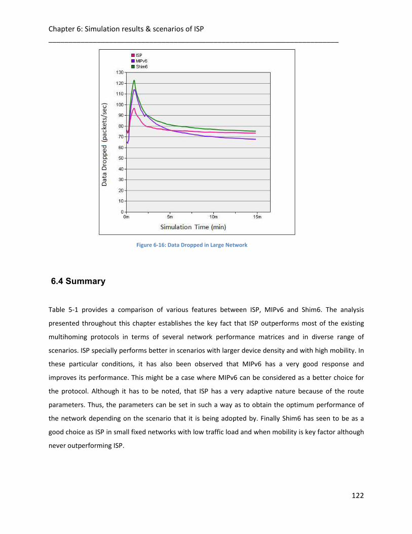
Chapter 6: Simulation results & scenarios of ISP ________________________________________________________________________
122
Figure 6-16: Data Dropped in Large Network
6.4 Summary
Table 5-1 provides a comparison of various features between ISP, MIPv6 and Shim6. The analysis
presented throughout this chapter establishes the key fact that ISP outperforms most of the existing
multihoming protocols in terms of several network performance matrices and in diverse range of
scenarios. ISP specially performs better in scenarios with larger device density and with high mobility. In
these particular conditions, it has also been observed that MIPv6 has a very good response and
improves its performance. This might be a case where MIPv6 can be considered as a better choice for
the protocol. Although it has to be noted, that ISP has a very adaptive nature because of the route
parameters. Thus, the parameters can be set in such a way as to obtain the optimum performance of
the network depending on the scenario that it is being adopted by. Finally Shim6 has seen to be as a
good choice as ISP in small fixed networks with low traffic load and when mobility is key factor although
never outperforming ISP.

Chapter 6: Simulation results & scenarios of ISP ________________________________________________________________________
123
Table 6-1: Comparison of Various Features between ISP, MIPv6 and Shim6

Chapter 7: Proposed schemes in WiMAX ________________________________________________________________________
7
Chapter 7124
PROPOSED SCHEMES IN WIMAX
7.1 Introduction
IEEE 802.16 wireless networks require wide bandwidth and high-speed mobility, and IEEE 802.16e is
considered to be a technology capable of meeting such requirements. The standard is proposed to
support the mobility up to 70mile/hour with the data transmission rate up to 2Mbps as mentioned in
earlier section, so handover has become one of the most important factors that impact the performance
of IEEE 802.16e system. Data transmission to the terminal device is interrupted while scanning is
performed for the handover procedure. Naturally, prolonged scanning undermines the network’s
performance. In order to resolve this problem, a number of handover schemes have been proposed. In
order to reduce the redundancies and improve the network reception during IEEE 802.16e handover
process, fast handover solutions were proposed for this purpose.
The first solution, FCS (Fast Channel Scanning), has been proposed. Its solution is to improve the mobile
WiMAX handover and address the scanning latency. Since minimum scanning time is the most important
issue in the handover process. This handover scheme aims to utilize the channel efficiently and apply
such a procedure so as to reduce the time it takes to scan the neighboring base stations. This implies
that the un-necessary scanning of neighboring base stations should be avoided by reducing the number
of base stations to be scanned by performing negotiation prior to scanning.
The second solution, Traffic Manager (TM) is to adapt the channel congestion problem and how it
severely restricts the amount of critical video streams, introducing an algorithm that based on the
channel bandwidth information, and assigning different channel for each connection.
The core idea is that when an MS is transmitting a video application through the assigned channel to the
serving BS, and this channel capacity is over loaded, therefore, this MS will try to find an alternative path

Chapter 7: Proposed schemes in WiMAX ________________________________________________________________________
125
to forward its additional application streams. This dilemma use case led to the development of our
Traffic Manager (TM).
The proposed schemes are new reliable handover schedules, which are essentially succession of wireless
interface switching criterions. They are able to provide a reliable communication route with assurance of
good bandwidth (data-rate), lower handover latency and route path optimization. The design of the
schemes is based on a novel cross layer information exchange mechanism which enables to use various
network related parameters from different layers (Link/ Physical layers) across the protocol suite for
decision making at the Network layer.
Since in Network layer, ISP proposed approach is being used which is an adaptive in terms of the route
selection process. The default route (Which uses the optimum values of cross layer parameters) can
always be overridden by changing the parameters according to the type of applications. In other words,
it implies that between the same source and destination there might be different paths.
For packet forwarding if there are different types of applications active on the source and destination.
The route maintenance process often becomes extremely challenging owing to the highly variable
nature of wireless medium (interference, distance between transmitter and receiver etc) and frequent
movement of participating nodes in a wireless network causing topological changes in the network. To
cope with this issue proposed scheme always maintains an alternative route in parallel to the primary
route. It implies that at every node if the packet forwarding fails for some reason on the primary route
the alternative path always exists which can used instead of initiating a new route rediscovery process.
7.2 Contributions of the Proposed Schemes
This chapter explores the possibility of supporting video applications streams over WiMAX devices with
multiple interfaces and show how the quality of multiple streams can be improved.
Specifically, the Contributions of the proposed schemes are listed in several points as follows:

Chapter 7: Proposed schemes in WiMAX ________________________________________________________________________
126
• Handover Latency: We show how the handover latency will be reduced when eliminating
unnecessary BSs by performing negotiations with neighboring BSs prior to scanning, and select
the target BS according to the bandwidth requirement.
• Bandwidth Consumption:
1. To adapt the features of bandwidth consumption issue. We provide broadcast synchronization
among multi- BSs through the cooperation between the proposed server and BSs. In other words,
same video content will be transmitted at the same time and in same bandwidth across multi-BSs.
In this way, a seamless handover can be achieved from one cell to another in a feasible way.
2. When using a multicast video codec here, we’ll have different types of encoded data streams
according to the required bandwidth from different users. This will enforce us to use different
transmission channels, i.e. some channel will transmit high bit-stream data, and another will
transmit the low bit-stream data which is demanded by most users. This attempt can reduce the
total bandwidth consumption.
3. In addition, since the same server with video codec will be used to connect to another sub-network.
This will reduce the chances to multi-copy the same required data to different users. This will
reduce the bandwidth consumption as well.
• Channel Congestion: Since we detect the deterioration of the wireless link when transmitting a
video application through the current assigned channel and this channel capacity is facing traffic
congestion issue resulted in the application quality degradation. We design an algorithm based
on the channel information to enable the MS to switch to a Two-path transmission in order to
prevent packet loss and transmit the data packets on both interfaces. While video traffic stream
congested, the latency should be no more than 4-5 seconds.
• Multipath Transmission: When using multipath transmission method, this will enhance us to
use lower bandwidth and lower channel frequencies across the network.
Chapter 7: Proposed schemes in WiMAX ________________________________________________________________________
127
• Finally, we conduct our simulations to verify our proposals and analysis the effects of different
parameters on the HO latency. It can provide full multi-homing support through the
simultaneous utilization of all available paths, which achieves load sharing and increases an
application’s throughput, achieving significant reductions in term of data dropped ratios, the
end-to-end delay and bandwidth consumption.
7.3 Criterion Effecting Handover-Analysis
From the IEEE 802.16e standard handover procedures (detailed in chapter 2) may affect the video
broadcast performance over WiMAX from a reason to another. This motivates us to highlight some
issues which may lead to handover decision in ubiquitous WiMAX:
1. MS Synchronization across Multi-BS
Synchronization of MS across multi-BS is hard to achieve since the same application i.e., video stream
content has to be transmitted in the same OFDMA frame and by the same channel usage. The MS
synchronization is critical to achieve macro-diversity, reducing interference and reducing the handover.
The reason why it is hard to achieve synchronization is as follows. As we know, the delay to transmit
video data packet copy from MS to BSs varies over time and varies across multiple BSs. Video data
packet copy could also be lost during transmission from the MS to some BS. However, each BS makes its
own scheduling decision. Therefore, most likely, the same OFDMA region will not transmit the same
video data packet. Thus, video packets may have to be dropped due to buffer overflow at BS side that
may cause an additional delay. Video quality could vary significantly if it is dropped randomly because
some important video packets could be dropped during transmission on the communicating channel
between the MS and the BSs.
Therefore, the total synchronization latency is calculated as:
Tsync= Tsyncs*K (1)
As the Tsync is the standard Synchronization latency.
K : Number of the BSs.
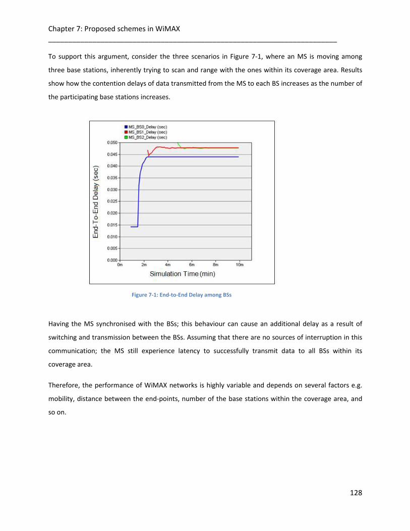
Chapter 7: Proposed schemes in WiMAX ________________________________________________________________________
128
To support this argument, consider the three scenarios in Figure 7-1, where an MS is moving among
three base stations, inherently trying to scan and range with the ones within its coverage area. Results
show how the contention delays of data transmitted from the MS to each BS increases as the number of
the participating base stations increases.
Figure 7-1: End-to-End Delay among BSs
Having the MS synchronised with the BSs; this behaviour can cause an additional delay as a result of
switching and transmission between the BSs. Assuming that there are no sources of interruption in this
communication; the MS still experience latency to successfully transmit data to all BSs within its
coverage area.
Therefore, the performance of WiMAX networks is highly variable and depends on several factors e.g.
mobility, distance between the end-points, number of the base stations within the coverage area, and
so on.
Chapter 7: Proposed schemes in WiMAX ________________________________________________________________________
129
2. Application Size
There is a possibility of large-size video frame to be transmitted and share the medium. This may arise a
congestion issue since the same channel will carry the same video data packets. Therefore, the video
quality will degrade significantly when MS experience temporal fading or interference.
In addition, the burst transmission mechanism allows multiple MAC PDUs belonging to the same video
channel to be exchanged between the MS and the BS in an aggregate way [1]. And if the burst size is big
which may consist of many OFDMA slots, this may cause an additional Delay Value to the channel access
operation.
For connections that require enhanced reliability, WiMAX supports automatic retransmission requests
(ARQ) at the link layer. ARQ-enabled connections require each transmitted data packet to be
acknowledged by the receiver node and allow feedback to be received at the transmitter side to
understand the ongoing call quality and the channel status. As a result of the congested channel issue,
unacknowledged packets are assumed to be dropped and will be retransmitted again that may assemble
a huge queuing which may cause an additional latency.
Consider the scenario in figure 7-2, where the MS is communicating with BS through an assigned
wireless channel. Because of unacknowledged packets at the MS’transmitter, these uplink packets are
assumed to be dropped and their retransmission again may cause an additional latency.

Chapter 7: Proposed schemes in WiMAX ________________________________________________________________________
130
Figure 7-2: Average Data Dropped in the Congested Medium
The purpose of showing this graph significant to the current argument being made here is that the Data
Dropped (Packets/sec); this statistic shows the higher layer data traffic dropped (in Packets/sec) by the
WiMAX MAC due to data buffer overflow as a result of the congested channel issue.
3. Bandwidth Consumption
Since the data traffic quality are dropped. Thus results in more resource will be released into the
available medium bandwidth. It should be mentioned that if the retransmission is done among, e.g. the
video programs, until the total available bandwidth is used up. This procedure would consume the
bandwidth amounts without any chance to reserve minimal guaranteed amounts. Therefore, it’s more
convenient to release the bandwidth resource, and then the reservation scheduling will be fulfilled.
Therefore, it’s important to check the bandwidth availability whether it’s providing the enough amounts
in order to support the transmission of data applications with heavy traffic environment.
Therefore, to achieve a seamless handover in the WiMAX network the following three requirements
should be considered:
Chapter 7: Proposed schemes in WiMAX ________________________________________________________________________
131
1. Prompt and reliable detection of degradation in wireless link (channel) quality between end-
points (MS and BS).
2. Elimination of redundant handover processing elements on Network (if possible), Link and
Physical layers.
3. Selection of a better Target BS.
7.4 The Proposed Schemes
7.4.1. Fast Channel Scanning (FCS) based on Bandwidth information
The first proposed scheme shows that the scanning time can be reduced with the number of eliminated
BSs based on the negotiations procedure. Therefore the handover latency will be reduced.
7.4.1.1 Scanning Phase
The proposed scheme involves eliminating unnecessary BSs by performing negotiations with
neighboring BSs prior to scanning. Through the backbone message, a BS sends information to
neighboring BSs regarding the bandwidth required by the MS before the MS scans. A response from
neighboring BSs allows the protocol to assess the MS’s expected performance if the service is provided
by the corresponding BS. Then the MS scans only the BSs that satisfy its requirements.
In the scan phase of Handover (which was detailed in chapter 2), the MS scans and synchronizes with
the neighboring BSs based on channel information from the neighbour advertisement which is provided
by the serving BS. In order to find an appropriate BS target, The MS is scans all available BSs for a well-
known DL preamble frame, in order to negotiate and have the MS connected to a BS.
When MS is powered up, it first scans the allowed downlink (DL) frequencies to determine if it’s within
the coverage of a suitable WiMAX network. Then MS tries to synchronize with the stored DL frequency.
If this does not succeed, MS will try to synchronize with other suitable BSs DL frequencies. Since MS
regularly receives channel information about the neighboring BSs through the MOB_NBR-ADV message
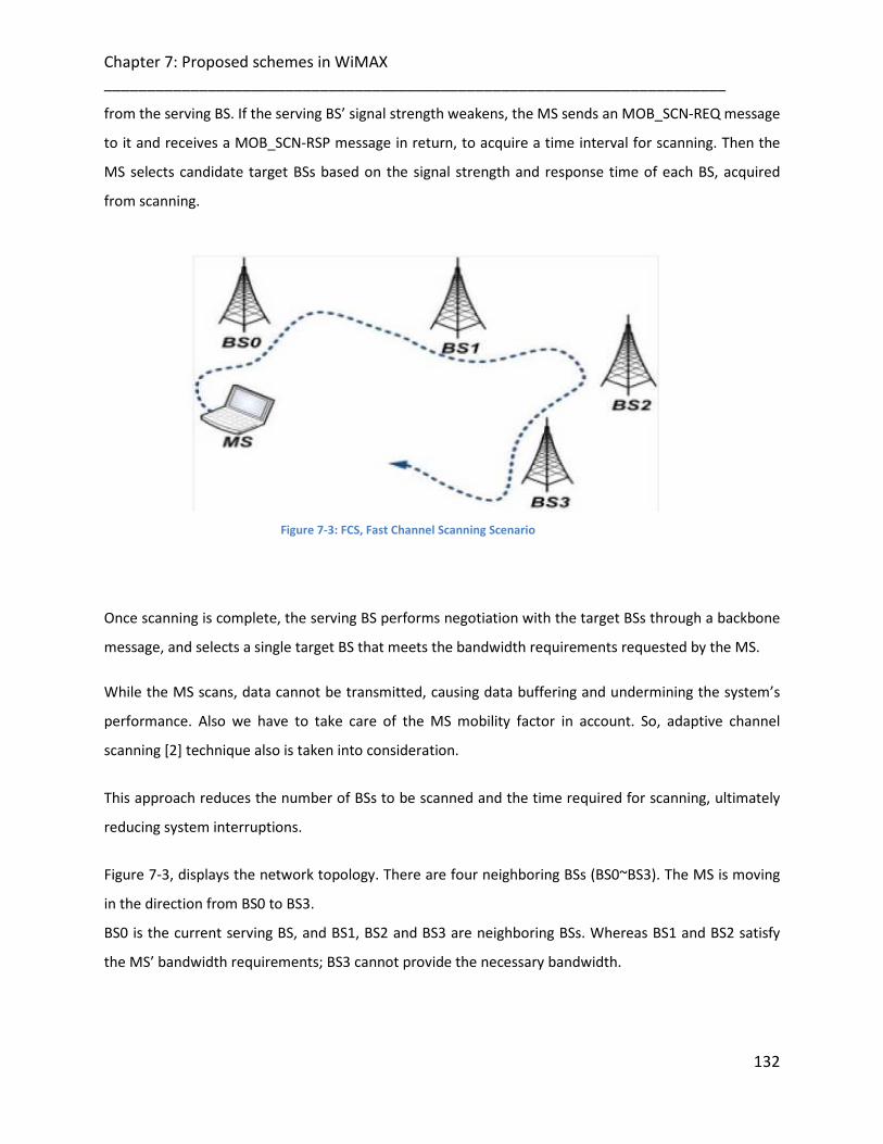
Chapter 7: Proposed schemes in WiMAX ________________________________________________________________________
132
from the serving BS. If the serving BS’ signal strength weakens, the MS sends an MOB_SCN-REQ message
to it and receives a MOB_SCN-RSP message in return, to acquire a time interval for scanning. Then the
MS selects candidate target BSs based on the signal strength and response time of each BS, acquired
from scanning.
Figure 7-3: FCS, Fast Channel Scanning Scenario
Once scanning is complete, the serving BS performs negotiation with the target BSs through a backbone
message, and selects a single target BS that meets the bandwidth requirements requested by the MS.
While the MS scans, data cannot be transmitted, causing data buffering and undermining the system’s
performance. Also we have to take care of the MS mobility factor in account. So, adaptive channel
scanning [2] technique also is taken into consideration.
This approach reduces the number of BSs to be scanned and the time required for scanning, ultimately
reducing system interruptions.
Figure 7-3, displays the network topology. There are four neighboring BSs (BS0~BS3). The MS is moving
in the direction from BS0 to BS3.
BS0 is the current serving BS, and BS1, BS2 and BS3 are neighboring BSs. Whereas BS1 and BS2 satisfy
the MS’ bandwidth requirements; BS3 cannot provide the necessary bandwidth.
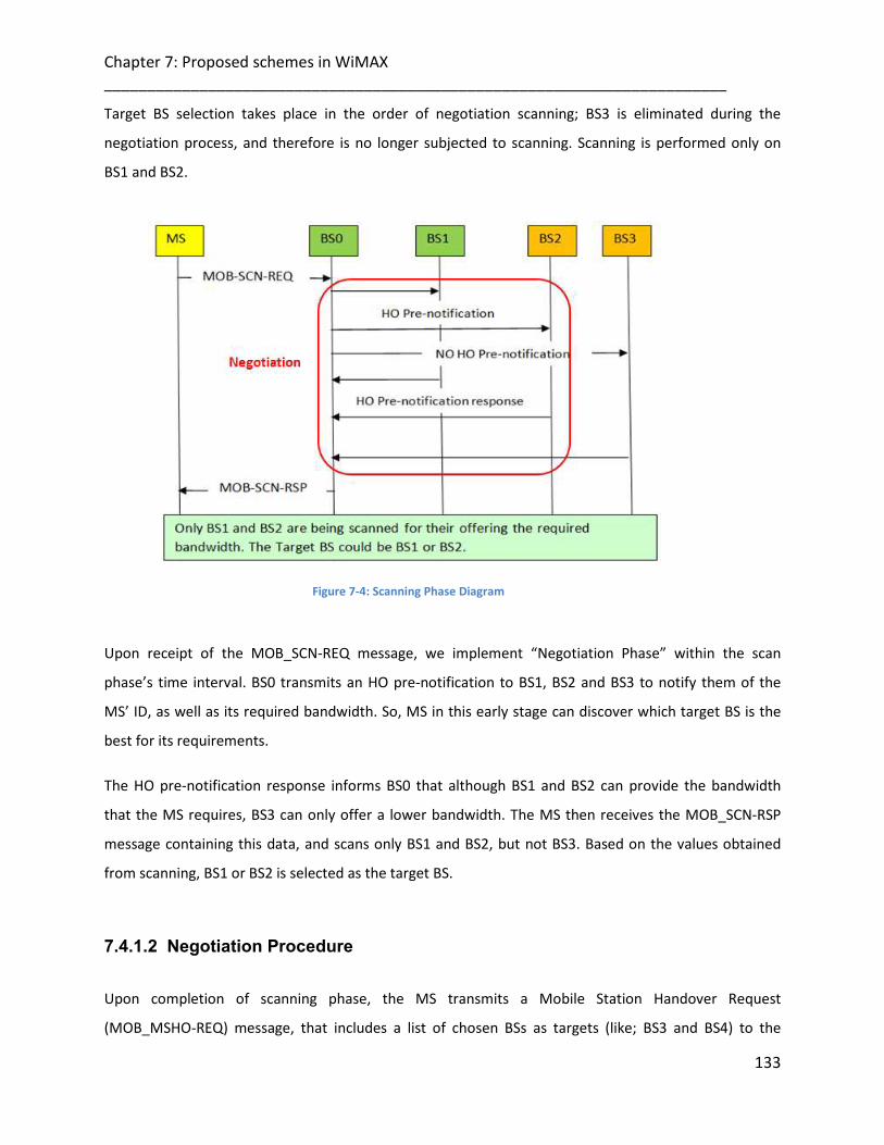
Chapter 7: Proposed schemes in WiMAX ________________________________________________________________________
133
Target BS selection takes place in the order of negotiation scanning; BS3 is eliminated during the
negotiation process, and therefore is no longer subjected to scanning. Scanning is performed only on
BS1 and BS2.
Figure 7-4: Scanning Phase Diagram
Upon receipt of the MOB_SCN-REQ message, we implement “Negotiation Phase” within the scan
phase’s time interval. BS0 transmits an HO pre-notification to BS1, BS2 and BS3 to notify them of the
MS’ ID, as well as its required bandwidth. So, MS in this early stage can discover which target BS is the
best for its requirements.
The HO pre-notification response informs BS0 that although BS1 and BS2 can provide the bandwidth
that the MS requires, BS3 can only offer a lower bandwidth. The MS then receives the MOB_SCN-RSP
message containing this data, and scans only BS1 and BS2, but not BS3. Based on the values obtained
from scanning, BS1 or BS2 is selected as the target BS.
7.4.1.2 Negotiation Procedure
Upon completion of scanning phase, the MS transmits a Mobile Station Handover Request
(MOB_MSHO-REQ) message, that includes a list of chosen BSs as targets (like; BS3 and BS4) to the
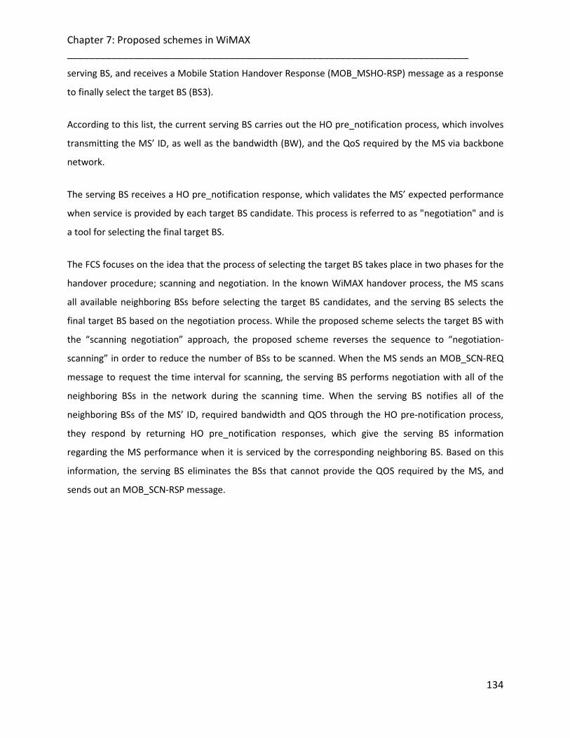
Chapter 7: Proposed schemes in WiMAX ________________________________________________________________________
134
serving BS, and receives a Mobile Station Handover Response (MOB_MSHO-RSP) message as a response
to finally select the target BS (BS3).
According to this list, the current serving BS carries out the HO pre_notification process, which involves
transmitting the MS’ ID, as well as the bandwidth (BW), and the QoS required by the MS via backbone
network.
The serving BS receives a HO pre_notification response, which validates the MS’ expected performance
when service is provided by each target BS candidate. This process is referred to as "negotiation" and is
a tool for selecting the final target BS.
The FCS focuses on the idea that the process of selecting the target BS takes place in two phases for the
handover procedure; scanning and negotiation. In the known WiMAX handover process, the MS scans
all available neighboring BSs before selecting the target BS candidates, and the serving BS selects the
final target BS based on the negotiation process. While the proposed scheme selects the target BS with
the “scanning negotiation” approach, the proposed scheme reverses the sequence to “negotiation-
scanning” in order to reduce the number of BSs to be scanned. When the MS sends an MOB_SCN-REQ
message to request the time interval for scanning, the serving BS performs negotiation with all of the
neighboring BSs in the network during the scanning time. When the serving BS notifies all of the
neighboring BSs of the MS’ ID, required bandwidth and QOS through the HO pre-notification process,
they respond by returning HO pre_notification responses, which give the serving BS information
regarding the MS performance when it is serviced by the corresponding neighboring BS. Based on this
information, the serving BS eliminates the BSs that cannot provide the QOS required by the MS, and
sends out an MOB_SCN-RSP message.

Chapter 7: Proposed schemes in WiMAX ________________________________________________________________________
135
Figure 7-5: Negotiation Phase Diagram
The known procedure involves scanning every neighboring BS, which decreases the system’s
performance due to suspended data transmission during the scanning process. On the other hand, the
negotiation process takes place through the backbone network, and does not interrupt data
transmission. Therefore, negotiation is performed prior to scanning, to identify the BSs that satisfy the
MS requirements. Only the selected BSs are scanned, decreasing the number of scans. This ultimately
reduces the suspension of data transmission.
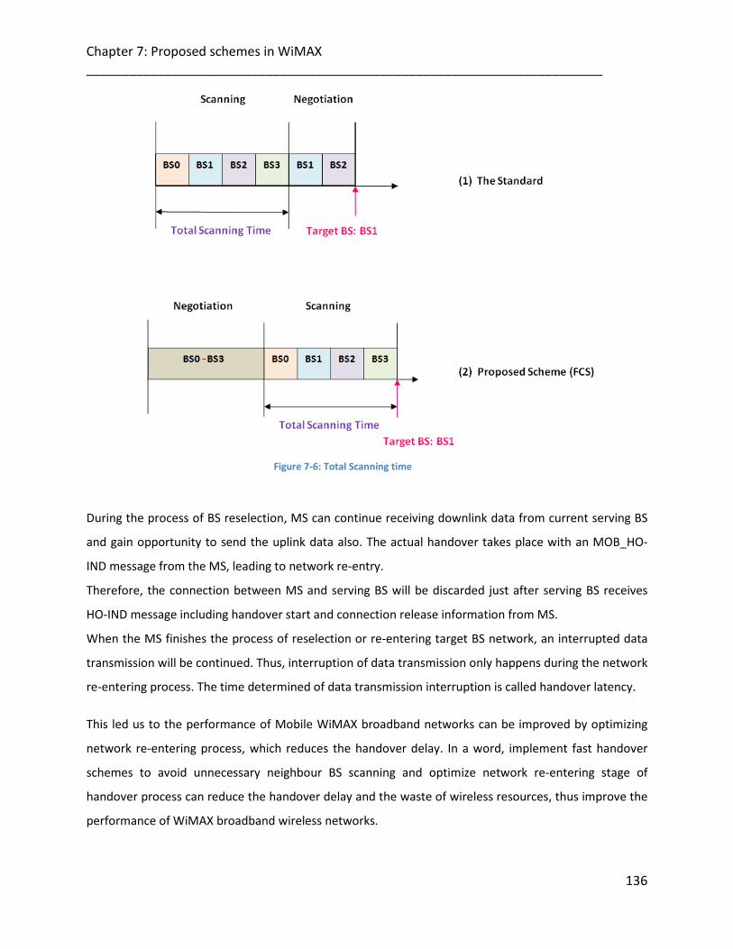
Chapter 7: Proposed schemes in WiMAX ________________________________________________________________________
136
Figure 7-6: Total Scanning time
During the process of BS reselection, MS can continue receiving downlink data from current serving BS
and gain opportunity to send the uplink data also. The actual handover takes place with an MOB_HO-
IND message from the MS, leading to network re-entry.
Therefore, the connection between MS and serving BS will be discarded just after serving BS receives
HO-IND message including handover start and connection release information from MS.
When the MS finishes the process of reselection or re-entering target BS network, an interrupted data
transmission will be continued. Thus, interruption of data transmission only happens during the network
re-entering process. The time determined of data transmission interruption is called handover latency.
This led us to the performance of Mobile WiMAX broadband networks can be improved by optimizing
network re-entering process, which reduces the handover delay. In a word, implement fast handover
schemes to avoid unnecessary neighbour BS scanning and optimize network re-entering stage of
handover process can reduce the handover delay and the waste of wireless resources, thus improve the
performance of WiMAX broadband wireless networks.
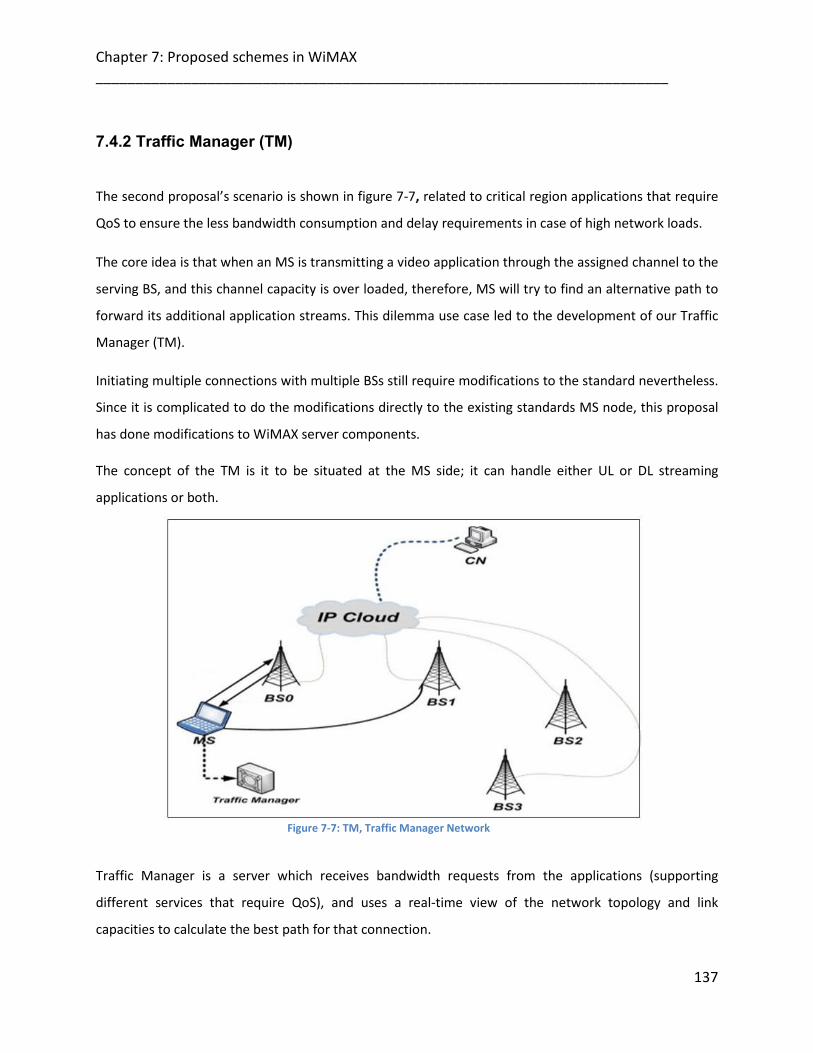
Chapter 7: Proposed schemes in WiMAX ________________________________________________________________________
137
7.4.2 Traffic Manager (TM) The second proposal’s scenario is shown in figure 7-7, related to critical region applications that require
QoS to ensure the less bandwidth consumption and delay requirements in case of high network loads.
The core idea is that when an MS is transmitting a video application through the assigned channel to the
serving BS, and this channel capacity is over loaded, therefore, MS will try to find an alternative path to
forward its additional application streams. This dilemma use case led to the development of our Traffic
Manager (TM).
Initiating multiple connections with multiple BSs still require modifications to the standard nevertheless.
Since it is complicated to do the modifications directly to the existing standards MS node, this proposal
has done modifications to WiMAX server components.
The concept of the TM is it to be situated at the MS side; it can handle either UL or DL streaming
applications or both.
Figure 7-7: TM, Traffic Manager Network
Traffic Manager is a server which receives bandwidth requests from the applications (supporting
different services that require QoS), and uses a real-time view of the network topology and link
capacities to calculate the best path for that connection.
Chapter 7: Proposed schemes in WiMAX ________________________________________________________________________
138
On this path, the demanded bandwidth is reserved for the lifetime of the connection. The MS must have
two interfaces at least. Two data streams pass by each other; they may occupy the same space and
bandwidth. To avoid flow interference each data stream should use different channel, here will require
channel assignment issue or use one of the interfaces for one flow and the second interface for the
other flow with a condition that the two interfaces are using different channels not a single one. This
means that the first connections between the MS and the serving BS will be reserved over this path,
without disconnecting it, and when this is congested, other request will be routed along other paths
through the network. As a result, the network is able to adjust to dynamically changing traffic demands
of the applications, guaranteeing the demanded bandwidth, and supporting a higher possible
throughput between two WiMAX end points.
7.4.2.1 TM Server Entities In addition to WiMAX PHY/MAC layers, three entities are more functional and essential to support
Traffic Manager Server over WiMAX:
1. A correct central real-time view of the network topology, and an accurate estimation of the
bandwidth capacity of every channel between end points.
2. A central software module that can calculate the path and possible bandwidth for every
available neighbour BS for a bandwidth request within the network coverage (relies on “ISP”
protocol model algorithm).
3. A mechanism to ensure that not all BSs transmit the same data content with a single
connection, which may consume more bandwidth than it has been assigned.
Moreover, TM server; consists of an important entity (its structure is built in OPNET network modeler
[3]) that is responsible for mapping video channel ID to Connection ID (CID).
Upon receiving data packets in the server, those packets will be first stored as MAC service data units
(SDUs) in the queues. The stored SDUs will be treated differently depending on the information types
and MAC controls.

Chapter 7: Proposed schemes in WiMAX ________________________________________________________________________
139
The TM server at first should collect the channel condition and translate the information to relative
available bandwidth. Therefore, transmitting TM-MAC-PDU over WiMAX PHY/MAC burst scheduling and
allocating OFDMA data region for each PDU and associating mapping video channels to multicast CIDs
will be known to all BSs belonging to the same TM server geographical zone.
On the other hand, the TM server is able to support multiple MAC connections according to the multiple
interfacing. Therefore, provides different levels of QoS for several connections. As the corresponding
SDU of each connection is from the server, the server should also have the capability of categorizing the
video bitstream to multiple level of importance as mentioned. The TM server can decide the number of
the video packets for the uplink transmission. Because the video files will be encoded by the scalable
video coding, it comprises some important frames from less important ones (discussed later). This server
can prioritize the packets and decide which packets can be delivered depending on the channel’s
bandwidth availability and according to the application needs.
7.4.2.2 Routing Technique
To explain how the routing is performed in the TM network, we divided the TM scheme into three
phases that covers all the routing operation. The first phase is the interface switching phase where the
source tries to find a better link to the destination (this will take place in PHY, MAC layers). The second
phase, applying scalable codec technique to divide the data streams into the two links. The third phase,
called the Route phase (which is done in IP layer) where the ISP has the routing operations implemented
in here.
7.4.2.2.1 Transmission to another Interface Algorithm (Based on “ISP” Two-Path Transmission Algorithm)
We assume resources are fully used in video broadcasting and the overhead for communication channel
is neglected. Since the TDD, OFDMA modes are deployed; bandwidth resources will be represented by
time slots.
As there are different levels of data to be transmitted, the TM server is able to support multiple
connections for that transmission. MS is transmitting a video application through the first interface

Chapter 7: Proposed schemes in WiMAX ________________________________________________________________________
140
channel to its serving BS, and this channel capacity is facing traffic congestion issue resulted in the
application quality degradation. Therefore, MS will try to find an alternative path to forward its
additional application streams. MS will start an association context with Traffic Manager.
The MS first interface (IF1) informs the TM of the Bandwidth value whenever an ACK frame is received
or the Bandwidth value reaches the Bandwidth-limit. After recording the Bandwidth value in BAN1, the
TM compares BAN1 with the Bandwidth-limit which is the threshold for switching to another network
interface. In the case that BAN1 less than the Bandwidth-limit, the TM detects the deterioration of the
condition of the wireless link bandwidth and switches to the Two-path transmission in order to prevent
packet loss and transmit the data packets on both interfaces.
In the Two-path transmission, since the MS sends data packets to the CN through both WiMAX
interfaces, the networks load increases. When switching to the Two-path transmission, the Bandwidth
value that a packet experiences is used as a switching criterion. The MS second WiMAX interface is
assigned to communicate with the TM.
The MAC retransmission in the proposed scheme can be useful to increase the system robustness, thus
decrease the video packet loss ratio.
The traffic partially transmitted on one interface and the rest on the 2nd interface, e.g. the most
important data that is demanded by most users (basic data) on one interface and the less important
data (enhanced data) on the other interface. The traffic from two interfaces is not duplication of one
another but can be combined.
In the case of moving to another BS without Two-path transmission, the communication quality might
be degraded due to not knowing the condition of the next wireless link in advance. Therefore, the TM
should investigate the condition of both wireless links (interfaces) using Two-path transmission when
the Bandwidth value is becoming low. Then, when the TM discovers a BS that has a wireless link of good
condition, the transmission returns to One-path transmission through this BS.
1. The MN first interface (IF1) fills the field of the Bandwidth value whenever an ACK frame is
received or the Bandwidth value reaches the Bandwidth-limit.
2. In each entry the accumulated “Bandwidth” value of the path is stored in both MS and the TM
server.

Chapter 7: Proposed schemes in WiMAX ________________________________________________________________________
141
3. MS checks the Bandwidth value received if it’s decreased. If yes, MS should start the context
with TM.
4. TM records the Bandwidth value in BAN1 (Bandwidth variable value, same as the one used in ISP
probing message parameters), the TM compares BAN1 with the Bandwidth-limit which is the
threshold for switching to another network interface.
5. In the case that B1 less than the Bandwidth-limit, the TM detects the deterioration of the
condition of the wireless link and switches to the Two-path transmission in order to prevent
packet loss and transmit the data packets on both interfaces.
Figure 7-8: Transmission to another Interface Algorithm
(Based on “ISP” Two-Path Transmission Algorithm)
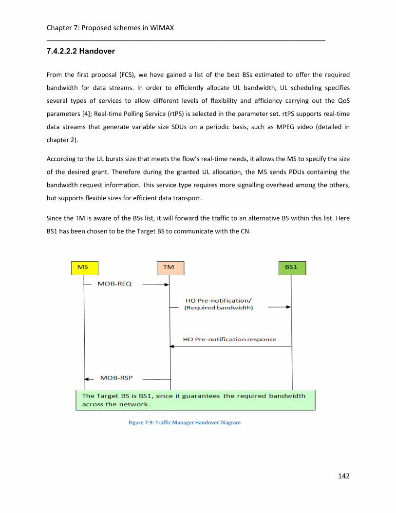
Chapter 7: Proposed schemes in WiMAX ________________________________________________________________________
142
7.4.2.2.2 Handover
From the first proposal (FCS), we have gained a list of the best BSs estimated to offer the required
bandwidth for data streams. In order to efficiently allocate UL bandwidth, UL scheduling specifies
several types of services to allow different levels of flexibility and efficiency carrying out the QoS
parameters [4]; Real-time Polling Service (rtPS) is selected in the parameter set. rtPS supports real-time
data streams that generate variable size SDUs on a periodic basis, such as MPEG video (detailed in
chapter 2).
According to the UL bursts size that meets the flow’s real-time needs, it allows the MS to specify the size
of the desired grant. Therefore during the granted UL allocation, the MS sends PDUs containing the
bandwidth request information. This service type requires more signalling overhead among the others,
but supports flexible sizes for efficient data transport.
Since the TM is aware of the BSs list, it will forward the traffic to an alternative BS within this list. Here
BS1 has been chosen to be the Target BS to communicate with the CN.
Figure 7-9: Traffic Manager Handover Diagram

Chapter 7: Proposed schemes in WiMAX ________________________________________________________________________
143
7.4.2.2.3 Delay
In this case, End-to-end delay (consisting of network delay and packetization delay). Network delay is
the one-way delay from the MS to the CN across the WiMAX network. Packetization delay is the delay
associated at the receiver-side decoder buffer that is responsible to queuing and smoothing out the
jitter for the arriving packet streams.
Thus, the total delay is
DT = DN + DP (2)
DT: the total delay, DN: Network delay, DP: packetization delay
7.4.2.3 WiMAX PHY/MAC Entities
In the following section, some PHY/MAC layer mechanisms are highlighted, which in a way or another,
their use had participated in the reduction of the overall delay.
7.4.2.4 ARQ (Auto-Retransmission Request)
As known, the data packets often get lost or corrupted during transmission in the wireless channels,
ARQ mechanism is usually used to identify these lost frames [5]. ARQ will play an essential role in
estimating the channel condition and the destiny of the MPDUs that have been transmitted. When the
channel is in good state, no retransmissions are required and no bandwidth is wasted [6].
On other hand, the round-trip time “RTT” is important in determining the size of the MAC PDUs (RTT:
the time difference between the time when the last bit of an MAC PDU is transmitted and the time
when the acknowledgment of that MAC PDU is received). We assume a small time interval between the
transmissions of two consecutive MPDUs, that is, the last bit of an MPDU and the first bit of the next
MPDU are transmitted edge to edge. Moreover, the increase in the number of streams may result in
degradation of the channel performance, since streams slots share the common channel bandwidth.
Thus, greater numbers of streams will consume more bandwidth, resulted in bandwidth allocation for
each stream is decreased.

Chapter 7: Proposed schemes in WiMAX ________________________________________________________________________
144
Therefore, the increase in number of streams may increase the number of retransmissions, and there
will be more packets are being queued to be transmitted or retransmitted in the backhaul. This
perceptually will increase the packets delay and introduces jitter at the receiver.
7.4.2.5 FEC (Forward Error Correction) FEC is responsible to add redundant information so that original message can be recovered in presence
of bit errors [7]. The FEC redundancy ratio (the ratio of redundant bit number to total bit number) has to
be large enough to guarantee the service requirements when the current channel condition is bad. FEC’s
work is combined to BER (Bit Error Rate) role, both compatible to varying wireless channel condition.
FEC works well only when BER is stable. If the number of bit errors exceeds the FEC code's recovery
capability, the FEC code cannot recover any portion of the original data. In other words, FEC is useless
when the BER exceeds the decided threshold thus reduce the recover chances of the FEC code. When
the wireless channel is in good condition (means the BER is very small), using FEC will cause unnecessary
overhead and consume more bandwidth.
7.4.2.6 WiMAX PHY/MAC at the MS Side After the MS has indicated its PHY/MAC layers to obtain information on the available channels via a
request sent to the serving BS, the BS transmits a ranging response which provides the initial ranging,
timing, and power information to the MS, and a basic connection ID is provided to the MS. After MAC
SDUs first obtained from the MAC-convergence sublayer, the common part sublayer has packed or
fragmented MAC SDU into multiple desired size MAC PDUs. It encodes only the PDUs (TM-MAC-PDUs in
this case) associated with each corresponding channel ID that translated into CID. Then MS will
continue copying the channels information to the TM server, even If the server is in silent mode.

Chapter 7: Proposed schemes in WiMAX ________________________________________________________________________
145
Figure 7-10: SDU Fragmentation
Each TM-MAC-PDU contains (6 Byte) MAC header, Long Byte payload section and (4 Byte) CRC.
Cyclic redundancy check (CRC) is generated for each SDU section fragmented into PDU such that the
decoder at CN side can still tell whether the section has error, thus increasing error coding efficiency.
Thus, by checking the CRC, the system can determine which section has error. Forward Error Correction
(FEC) is used to improve the VoIP perceived quality. If some redundant bits in the form of FEC are
applied before transmission at the MS, then there is a probability that the CN would be able to detect
and correct the errors.
Although the application of FEC enhances the packet restore probability, the system performance can
still be further improved if the optional ARQ mechanism is enabled at WiMAX MAC common part
sublayer, for connections that require enhanced reliability, WiMAX supports automatic retransmission
requests (ARQ) at the link layer. ARQ-enabled connections require each transmitted data packet to be
acknowledged by the receiver node and allow feedback to be received at the transmitter side to
understand the ongoing call quality and the channel status. Thus the MAC common part sublayer gets
the information if a packet has been successfully received or not.
7.4.2.7 TM Silent Mode
An important amendment worth noting is that of silent mode. Since the mobility is introduced in here,
it’s obvious to mention the power as a concern. If the TM server is running all the time even if the
Chapter 7: Proposed schemes in WiMAX ________________________________________________________________________
146
network condition is good, this may not be able to recharge their unit for quite some time, and so it is
important to look at ways in which power can be conserved.
In silent mode, the TM is still receiving channel information from the MS but does no action and so it can
set its power usage to the minimum. Initially, the TM may go into silent mode for a period of time
known as TMt. When this has reached a maximum interval length a TMtmax, the TM leaves silent mode
and starts listening to short time intervals to check if there is any order from the MS for it. If not, it
resumes silent mode and thus, will save further power.
7.4.2.8 WiMAX PHY/MAC At BS Side
Upon receiving the data packets, it applies PHY channel coding (specified by TM server) to each TM-
MAC-PDU and maps each TM-MAC-PDU to the corresponding OFDMA data region slots (determined by
TM server) to be ready for transmission throughout the base station. One Traffic Manager Downlink or
Uplink data Information Element (TMDL/UL-DATA-IE) message is mapped for each DL and UL Bursts,
then will be transmitted in TM-MAP (at the beginning of TM zone) to indicate the CID and OFDMA data
region. The MAP message contains Information on DL/UL burst allocation, Physical layer control
message (Information Element (IE)) and management message (CRC) which is used to check the data
errors.
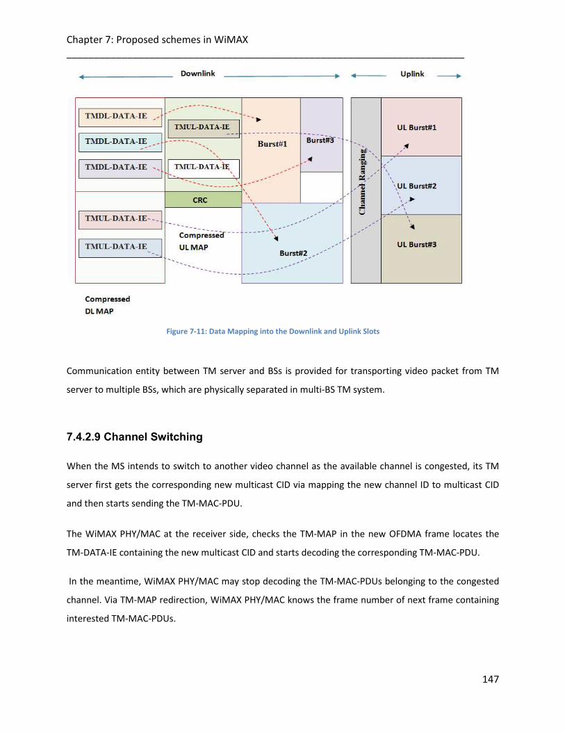
Chapter 7: Proposed schemes in WiMAX ________________________________________________________________________
147
Figure 7-11: Data Mapping into the Downlink and Uplink Slots
Communication entity between TM server and BSs is provided for transporting video packet from TM
server to multiple BSs, which are physically separated in multi-BS TM system.
7.4.2.9 Channel Switching
When the MS intends to switch to another video channel as the available channel is congested, its TM
server first gets the corresponding new multicast CID via mapping the new channel ID to multicast CID
and then starts sending the TM-MAC-PDU.
The WiMAX PHY/MAC at the receiver side, checks the TM-MAP in the new OFDMA frame locates the
TM-DATA-IE containing the new multicast CID and starts decoding the corresponding TM-MAC-PDU.
In the meantime, WiMAX PHY/MAC may stop decoding the TM-MAC-PDUs belonging to the congested
channel. Via TM-MAP redirection, WiMAX PHY/MAC knows the frame number of next frame containing
interested TM-MAC-PDUs.

Chapter 7: Proposed schemes in WiMAX ________________________________________________________________________
148
Since TM server can locate and decode only the packets on the video channel currently being watched,
no power will be wasted for decoding unwanted video packets. This may optimize the power
consumption issue if required.
7.4.2.10 WiMAX PHY/MAC at the Correspondent Node (CN)
CN consists of similar components as at the MS side, with some additional entities to decode those TM-
MAC-PDUs associated with the selected multicast CID. Error correction of the received frames decrypts
and constructs video packet according to standard SVC video decoding. As the CN’s receiving its data
burst, it should check the correctness and sequence of each MAC PDU and should acknowledge the BS.
7.4.2.11 SVC (Scalable Video Coding)
In this section, we discuss the concept of the framework for transporting scalable video over wireless
network interfaces.
As mentioned before, the adaptation algorithm typically calls for the use of the highest modulation and
coding scheme that can be supported by the signal-to-noise and interference ratio at the receiver such
that each user is provided with the highest possible data rate. In addition to those coding techniques,
we have selected the Scalable Video Coding (SVC) as detailed in [8] as the codec used in the server
which is an extended version of MPEG-4 H.264/AVC (for Advanced Video Coding) where the video
quality degradation is smooth when users move within and across cells.
SVC is a video coding technology that encodes the video at different layers and provides different
resolutions allowing the data bit-stream to be adapted to provide various lower resolutions streams.
Result in several types of encoded data streams with a consideration to their bandwidth requirement.
Therefore, this layered structure leads us to think about structure that will allow important data to be
more protected and provide more efficient video transmission over an assigned channel with an
adaptive bandwidth. The framework aims is to provide scaling of the substreams based on the
bandwidth availability to meet the demand of the application quality.
Chapter 7: Proposed schemes in WiMAX ________________________________________________________________________
149
The framework consists of; Video frames representations, and how each of which has its own specified
QoS requirement which makes network support the QoS requirements of scalable video
representations. As wireless channel conditions change, this framework enables the video application
sender to scale the video streams and transport the scaled video streams to the receivers with
acceptable perceptual quality.
The main advantages of using SVC in the proposed scheme are:
1. Adaptively to network interfaces. When the direct channel between the MS and the BS has a specific
bandwidth capacity, and the user application requires bandwidth more than the issued for that
channel, therefore the use of a SVC at the network connection points could help improve the video
quality. This is because it selectively drops substreams we decide or issue instead of the randomly
dropping as a result of over loaded channel capacity.
2. When using a multicast video codec here, we’ll have different types of encoded data streams
according to the required bandwidth from different users. This will enforce us to use different
transmission channels, i.e. some channel will transmit high bit-stream data, and another will
transmit the low bit-stream data which is demanded by most users. This attempt can reduce the
total bandwidth consumption.
3. Lower complexity and lower delay, since SVC representations make the operation very simple, it
only discarding unimportant streams. Therefore, the processing is fast, compared with processing
without using the SVC.
4. In addition, since the same server with video codec will be used to connect to another sub-network.
This will reduce the chances to multi-copy the same required data to different users. This will reduce
the bandwidth consumption as well.
5. Lower handover dropping probability. The adaptability of using SVC at TM server between end-to-
end points can results in lower handover dropping probability.
The following diagram illustrates the Traffic Manager Framework.

Chapter 7: Proposed schemes in WiMAX ________________________________________________________________________
150
Figure 7-12: Traffic Manager Framework
7.4.2.12 Frame Representation
Since the Scalable codec provides multiple video representations in different resolutions. Each data
packet is subdivided into several small slots of time known as frames. These frames will have different
bandwidth and quality requirements. For example; some video frames are more important while the
others are less important. Some needs less transmission bandwidth due to its size or coarser quality;
and some requires more transmission bandwidth due to its finer quality. As a result, this scalability
achieves bandwidth organizing. That is, the same video content can be classifies at different rates.

Chapter 7: Proposed schemes in WiMAX ________________________________________________________________________
151
The different video packets can be transmitted in different bit-streams called substreams. On the other
hand, they can also be transmitted in the same bit-stream, which is called an embedded bit-stream. As
shown in Figure 7-13, an embedded bit-stream is formed by interleaving the basic data frames with the
refined frames. An embedded bit-stream is more flexible and bandwidth-scalable since the network
server (TM) can select certain traffic streams from an embedded bit-stream and discard them to match
the channel bandwidth availability.
Figure 7-13: Frame Representation
A: has more important data, needs less transmission bandwidth, low frame rate, and low quality
B: has less important data, requires more transmission bandwidth.
The bandwidth scalability of a video stream consists of SNR scalability, and temporal scalability. SNR is
used to quantify how much a signal has been corrupted by the noise, it is like a filter.
Table 7-1: Frames Temporal and SNR Scalabilities Ranges

Chapter 7: Proposed schemes in WiMAX ________________________________________________________________________
152
Q1 is a ratio indicates fewer signal than noise (Preferred by most users).
Q2 and Q3 respectively are ratios indicate more signals than noise.
Figure 7-14: SVC Scheduler
Since the base station notifies the MS about the channel quality (will be stored in TM server). Upon
receiving this information, the SVC module at the TM commands the scalar to perform as follows
(suppose that the video frame is compressed into two frames types A and B);
1. As known, wireless channels are typically much more noisy than the wired links and have both
small-scale (multipath) and large-scale (shadowing) fades [9], making the bit error rate (BER)
very high. The resulting bit errors can have devastating effect on video quality. Therefore, If the
BER is above a threshold, discard the (B frames) so that the bandwidth allocated for these
frames can be utilized by forward error correction (FEC) to protect the (A frames).
2. Otherwise transmit both Frames.
According to above, an open problem is come out: how many less important frames should be discarded
in favour of heavily FEC shielded more important frames (basic frames)?
The idea here has two advantages. Firstly, by taking the available bandwidth into account, the MS can
make the best use of network resources by selectively discarding (B frames) in order to minimize the
likelihood of more significant frames being corrupted, thereby increasing the perceptual quality of the
video delivered. Secondly, by considering the channel error status and since more robust FEC is used for

Chapter 7: Proposed schemes in WiMAX ________________________________________________________________________
153
packets containing (A frames) video subsequence than packet containing (B frames) video subsequence.
The MS can discard the (B frames) and FEC can utilize the bandwidth allocated for the (B frames) to
protect the (A frames), thereby maximizing the possibility of the (A frames) being correctly received.
In addition to BER or FEC, more techniques at physical/link layer are required to support this kind of
applications. Such techniques Code Division Multiple Access (CDMA) systems, Time Division Multiple
Access (TDMA) systems, channel quality estimation, and measurement feedback channel [10].
7.4.2.13 Interface Selection Protocol Role (ISP)
After all the physical parameter adjustments have been completed successfully, the network re-entry
process is initiated to establish connectivity between the MS and the target BS. This procedure may
include capability negotiation, authentication and registration transactions messages (details were
explained in handover procedures in chapter 2).
After the registration step has completed via exchanging the registration messages between the MS and
its BS, MS can now obtain the IP address. The ISP protocol selects an optimum IP route using a combined
route parameters of available bandwidth, minimum delay algorithm (details were explained in chapter
4). The duration of this phase should be taken into account the entire HO latency.
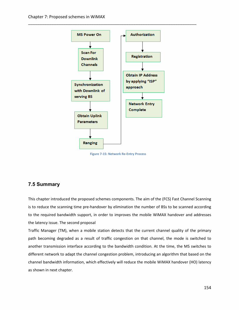
Chapter 7: Proposed schemes in WiMAX ________________________________________________________________________
154
Figure 7-15: Network Re-Entry Process
7.5 Summary
This chapter introduced the proposed schemes components. The aim of the (FCS) Fast Channel Scanning
is to reduce the scanning time pre-handover by elimination the number of BSs to be scanned according
to the required bandwidth support, in order to improves the mobile WiMAX handover and addresses
the latency issue. The second proposal
Traffic Manager (TM), when a mobile station detects that the current channel quality of the primary
path becoming degraded as a result of traffic congestion on that channel, the mode is switched to
another transmission interface according to the bandwidth condition. At the time, the MS switches to
different network to adapt the channel congestion problem, introducing an algorithm that based on the
channel bandwidth information, which effectively will reduce the mobile WiMAX handover (HO) latency
as shown in next chapter.

Chapter 7: Proposed schemes in WiMAX ________________________________________________________________________
155
7.6 References
[1] H Bernhard. Walke, S. Mangold, L. Berlemann, “IEEE 802 Wireless Systems”, John Wiley and Sons
Ltd, 2006.
[2] R. Rouil and N. Golmie, “Adaptive Channel Scanning for IEEE 802.16e,” Proceedings of 25th
Annual Military Communications Conference (MILCOM), Washington, D.C., October 23-25, 2006.
[3] OPNET Modeler, OPNET Technologies Incorporation. www.opnet.com.
[4] D. Lee, K. Kyamakaya and J. Umondi”Fast Handover Algorithm for IEEE 802.16e Broadband
Wireless Access System”, IEEE Computer and Communications Socities Conference (INFOCOM),
vol.3, pp. 985-992, April 1995.
[5] L. Hang and M. El Zarki, “Performance of H.263 Video Transmission over Wireless Channels Using
Hybrid ARQ,” IEEE J. Selected Areas in Comm., vol. 15, no. 9, pp. 1775-1786, Dec. 1997.
[6] S. Perera and H. Sirisena, “Contention-Based Negative Feedback ARQ for VoIP Services in IEEE
802.16 Networks,” Proc. 14th IEEE Int’l Conf. Networks, vol. 2, pp. 1-6, Sept. 2006.
[7] I. Joe, “An Adaptive Hybrid ARQ Scheme with Concatenated FEC Codes for Wireless ATM,” Proc.
ACM/IEEE MobiCom ’97, pp. 131- 138, 1997.
[8] H. Schwarz, D. Marpe, Member, IEEE, and T. Wiegand, Member, IEEE, “Overview of the Scalable
Video Coding Extension of the H.264/AVC Standard”, IEEE Transactions on Circuits and Systems
for Video Technology, vol. 17, no. 9, September 2007.
[9] B. Sklar, \Rayleigh fading channels in mobile digital communication systems Part I:
characterization," IEEE Commun. Mag., vol. 35, pp. 90{100, July 1997.
[10] S. Nanda, K. Balachandran, and S. Kumar, \Adaptation techniques in wireless packet data
services," IEEE Communications Magazine, pp. 54{64, Jan. 2000.

Chapter 8: Design/analysis of proposed WiMAX schemes in OPNET modeler ________________________________________________________________________
8
Chapter 8156
DESIGN/ANALYSIS OF PROPOSED WIMAX SCHEMES IN OPNET MODELER
8.1 Introduction
This chapter describes the WiMAX proposed schemes models in the OPNET modeler 14.0. The chapter
consists of two main sections. Firstly, the node design will be discussed with respect to the simulation
parameters and testing scenarios. Then a discussion will involve the adaptation of the proposed
schemes principles in a WiMAX node as presented in OPNET Modeler, also the newly introduced
simulation parameters together with all the old parameters provided by the WiMAX node in OPNET
Modeler will be identified and explained. The second section involves simulation results of the model
investigating the performance of the schemes. And scanning time and Handover latency of Fast Channel
Scanning (FCS) is analyzed. This analysis is embedded within the Traffic Manager (TM) scheme and
compared with the existing standard. The simulations results show that TM scheme can effectively
reduce the bandwidth consumption and eliminate the mobile WiMAX handover (HO) latency. Thus, the
simulation results prove that these fast handover schemes can reduce scan time and handover latency
during handover process, and thus improve the QoS of IEEE 802.16e.
8.2 Simulation Model
The OPNET v14.0 simulation tool [1]; is used in order to implement the scenario shown in figures 8-1.
OPNET provides flexibility by enabling the design of new communication protocols and devices, which
may be used along with a readily available library that has been developed.

Chapter 8: Design/analysis of proposed WiMAX schemes in OPNET modeler ________________________________________________________________________
157
8.2.1 Traffic Manager Network Design After the creation of the project in OPNET Modeler, the area of the network being simulated should be
defined to be of a reasonable size as in our example the area covered by 10000X8750 (meters), the
nodes are placed within the specified area as shown In the following scenario’s figure. In addition,
example of attribute values of each node will be also shown (the values of the required MS attributes in
the PHY/MAC layers will be discussed next). Simulation network model is consisting of the scenario in
figure 8-1. This scenario most commonly used in any wireless environment with either low or high load.
An example can be found at campus, airport networks etc.
The scenario as follows; the mobile station has two WiMAX interfaces. MS is communicating with the
correspondent node (CN) through IF1 to BS1, connected the wireless network to IP cloud which is used
here to represent the internet backbone connectivity. The MS’ second interface is connected to the
Traffic Manager server.
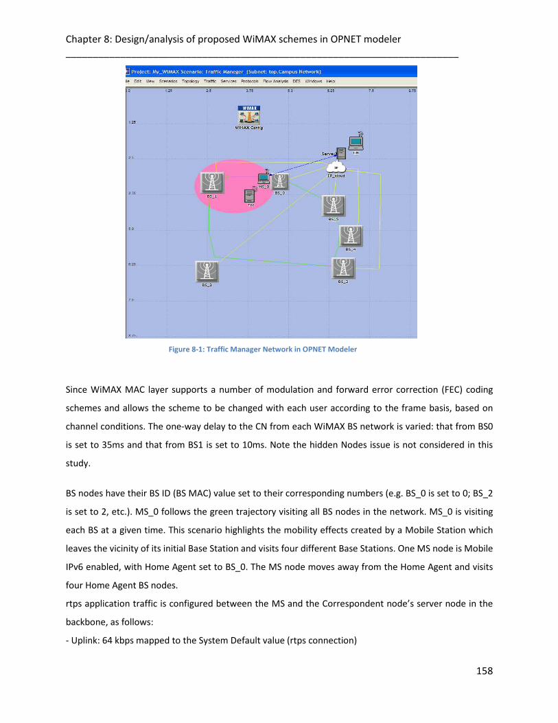
Chapter 8: Design/analysis of proposed WiMAX schemes in OPNET modeler ________________________________________________________________________
158
Figure 8-1: Traffic Manager Network in OPNET Modeler
Since WiMAX MAC layer supports a number of modulation and forward error correction (FEC) coding
schemes and allows the scheme to be changed with each user according to the frame basis, based on
channel conditions. The one-way delay to the CN from each WiMAX BS network is varied: that from BS0
is set to 35ms and that from BS1 is set to 10ms. Note the hidden Nodes issue is not considered in this
study.
BS nodes have their BS ID (BS MAC) value set to their corresponding numbers (e.g. BS_0 is set to 0; BS_2
is set to 2, etc.). MS_0 follows the green trajectory visiting all BS nodes in the network. MS_0 is visiting
each BS at a given time. This scenario highlights the mobility effects created by a Mobile Station which
leaves the vicinity of its initial Base Station and visits four different Base Stations. One MS node is Mobile
IPv6 enabled, with Home Agent set to BS_0. The MS node moves away from the Home Agent and visits
four Home Agent BS nodes.
rtps application traffic is configured between the MS and the Correspondent node’s server node in the
backbone, as follows:
- Uplink: 64 kbps mapped to the System Default value (rtps connection)

Chapter 8: Design/analysis of proposed WiMAX schemes in OPNET modeler ________________________________________________________________________
159
- Downlink: 64 Kbps mapped to the System Default value (rtps connection)
Note that the downlink traffic experiences more interruptions due to Layer 3 handover delays (via
Mobile IPv6) in addition to the Layer 2 handover delays (via WiMAX MAC functionality).
The green circles correspond to areas around each BS outside which the SNR of an MS transmission to
the BS drops below the scanning threshold of 27dB configured in the MS. Once the smoothed SNR drops
below the scanning threshold, scanning activity is started in the hope of identify other BSs as target for
handover. The scanning activity statistic shows that the scanning activity ends, once the MS successfully
changes its serving BS (as shown in the Serving BS ID statistic). Also each change of BS is preceded by
brief initial ranging, as shown in the Initial Ranging Activity statistic and as required by the Standard
during network entry.
After the MS attaches to the new serving BS, scanning still continues until the SNR at the MS receiver
gets within a 'comfortable' zone (higher than the SNR threshold for scanning). As explained above, the
'comfortable' zones are represented by the green concentric circles around each BS; for example, as the
MS passes by BS_5 without entering its green zone, the scanning activity continues as long as BS_5 is the
serving BS.
For the sake of easy interpretation of the Serving BS ID statistics, each BS has been assigned a MAC
address (or equivalently, BS ID) corresponding to its name, e.g. MAC 0 for BS_0, MAC 1 for BS 1 etc. Thus
it is clear from the Serving BS ID statistic that the MS associates consecutively with BS_0, BS_1, BS_2,
BS_3, BS_4 and BS_5.
The following figure shows the MS node model, MS has two WiMAX interfaces. (The details of the
process models are similar to the ones were explained in chapter 5, but WiMAX in the place of WLAN
components).

Chapter 8: Design/analysis of proposed WiMAX schemes in OPNET modeler ________________________________________________________________________
160
Figure 8-2: Mobile Station Node Model
8.2.2 WiMAX - MAC-Interface (MAC layer)
The IEEE 802.16 MAC layer provides functionality to allow reliable data delivery for the upper layers over
the wireless physical (PHY) media. The data delivery itself is based on an asynchronous, best-effort,
connectionless delivery of MAC layer data.
There is no guarantee that the frames will be delivered successfully.
IEEE 802.16 MAC provides a controlled access method to the shared wireless media called Carrier-Sense
Multiple Access with Collision Avoidance (CSMA/CA). CSMA/CA is similar to the collision detection
access method deployed by WLANs. By intelligent scheduling with a TDMA approach (in PHY layer),
WiMAX systems will be able to deliver not only high speed data by channel condition, but low latency
for delay sensitive services like VoIP, and allows an optimal transport for video applications different
priorities of traffic.
In addition, MAC layer allows an efficient bandwidth use, improves system capacity and minimize
channels interference. In addition, it provides the essential functionality for system and channel access,
allocation of bandwidth, and connection establishment and maintenance and handles the QoS
applications aspect of data transmission.
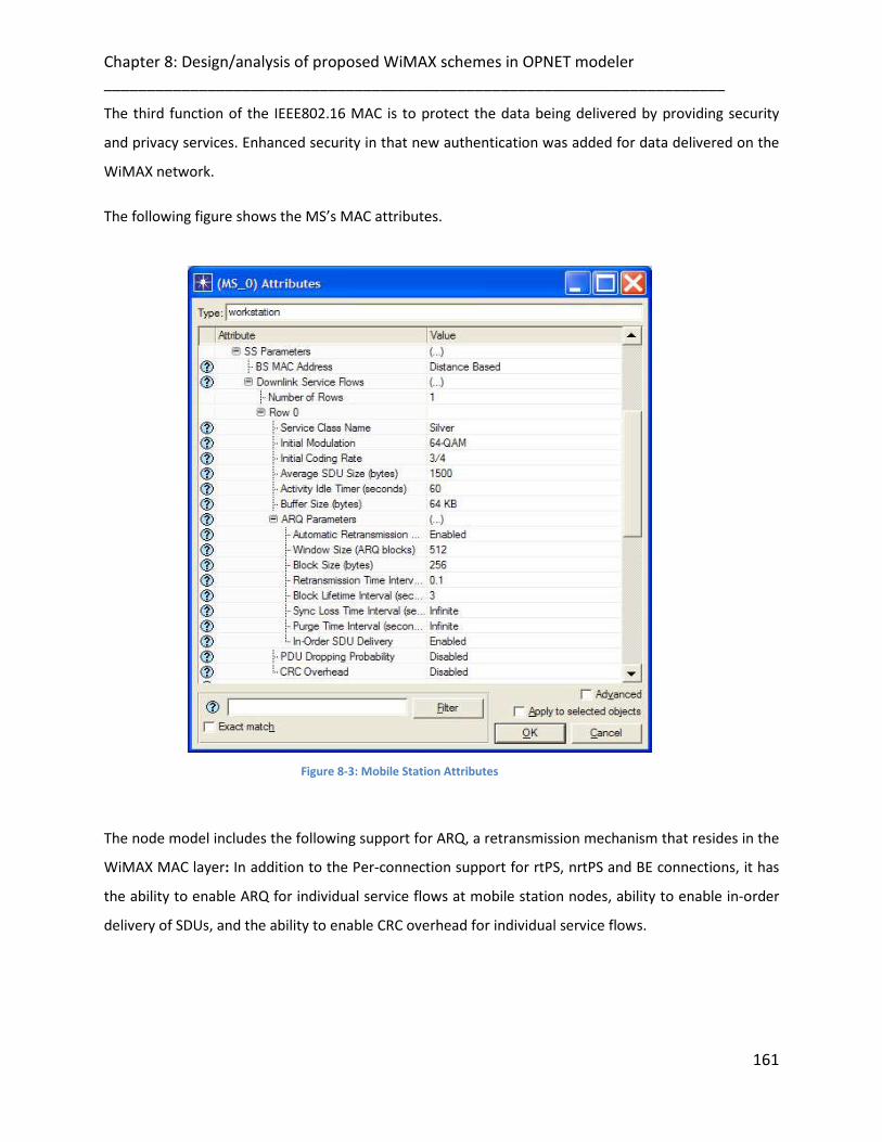
Chapter 8: Design/analysis of proposed WiMAX schemes in OPNET modeler ________________________________________________________________________
161
The third function of the IEEE802.16 MAC is to protect the data being delivered by providing security
and privacy services. Enhanced security in that new authentication was added for data delivered on the
WiMAX network.
The following figure shows the MS’s MAC attributes.
Figure 8-3: Mobile Station Attributes
The node model includes the following support for ARQ, a retransmission mechanism that resides in the
WiMAX MAC layer: In addition to the Per-connection support for rtPS, nrtPS and BE connections, it has
the ability to enable ARQ for individual service flows at mobile station nodes, ability to enable in-order
delivery of SDUs, and the ability to enable CRC overhead for individual service flows.
Chapter 8: Design/analysis of proposed WiMAX schemes in OPNET modeler ________________________________________________________________________
162
8.2.3 WiMAX- Transmission (Physical layer)
The WiMAX physical layer (PHY) as mentioned in earlier section is the interface between the MAC and
the wireless media where frames are transmitted and received. The PHY provides three functions. First,
the PHY provides an interface to exchange frames with the upper MAC layer for transmission and
reception of data. Secondly, the PHY uses signal carrier and spread spectrum modulation to transmit
data frames over the media. Thirdly, the PHY provides a carrier sense indication back to the MAC to
verify activity on the media.
8.2.3.1 Transmitter Node (Tx)
In the node model, the “Transmitter” module serves as the interface between packet streams inside a
node and communication links outside that node. There are several types of transmitter modules, in
respect to the types of communication links: like point-to-point and bus, in Wireless functionality, a
radio transmitter is used [2].
Transmitter is responsible to collect packets from one or more input packet streams and relay them over
corresponding channels within the communications link. A packet received on a given input stream is
transmitted over the channel with the same index number. Each channel can have its own data rate,
bandwidth, which can be used with the size of the packet to determine the transmission time. After
Packets arriving on an input stream while the corresponding channel is busy with a previous packet are
automatically queued in a buffer. This buffer has a default capacity of 1000 packets of any size.
Figure 8-4 shows the attributes for WiMAX transmitter (Tx). The attributes which are being used in the
simulation will be described in detail below.
The “data rate” attribute is the rate at which information may be forwarded over the data transmission
channel. The “bandwidth” attribute specifies the bandwidth of the channel. The “min frequency”
attribute specifies the base frequency of the channel.

Chapter 8: Design/analysis of proposed WiMAX schemes in OPNET modeler ________________________________________________________________________
163
Figure 8-4: Mobile Station's Transmitter Attributes
For more information on the exact operation of each of the models attributes used can be found in the
chapter of WiMAX model user guide in OPNET Modeler documentation.
Figure 8-5: Mobile Station's Transmitter Advanced Attributes

Chapter 8: Design/analysis of proposed WiMAX schemes in OPNET modeler ________________________________________________________________________
164
The transmitter communication direction can be uplink (UL) or downlink (DL) as shown in the Tx
attributes figure 8-5, if it is the UL direction, the buffer overflow at the BS will not happen as the packets
that cannot be sent will be queued up at the MS's Tx buffer, not at the BS.
8.2.3.2 Packet Loss Modeling
There two methods are available for modeling packet loss in the physical layer:
• When physical layer modeling is enabled in the attributes fields, the model accounts for packet losses
that are caused by physical layer effects.
• When the proposed framing representation module is enabled, we can configure mobile station nodes
to drop a certain percentage of the PDUs for a given flow or connection. Only one of these methods is
used during a simulation.
8.2.3.3 Traffic Organization in the Interfaces
Here some discussion on how the traffic is shared amongst the two interfaces.
Is the traffic duplicated on both interfaces for redundancy? Or is the traffic partly transmitted on one
interface and the rest on the 2nd interface? (E.g. the basic data on one and the enhanced data on the
other?)
If it is the first case, it’s simply via using the ARQ mode of transmission that should ensure no data loss
from the PHY link and redundant duplicated stream is not necessary. If the throughput is not enough
and the Tx queue is growing, why don't simply do HO to another BS with better throughput. What's the
benefit of sticking to the old BS, suffering inadequate throughput and going through the troubles of
initiating the second connection?
If it is the latter case, it does not increase the network load in the core network part as the traffic from
two interfaces is not duplication of one another but can be combined. Therefore,The traffic partially
transmitted on one interface and the rest on the second interface, e.g. the most important data that is
demanded by most users (basic data) on first interface and the less important data (enhanced data) on
the other interface. The traffic from two interfaces is not duplication of one another but can be
combined.
Chapter 8: Design/analysis of proposed WiMAX schemes in OPNET modeler ________________________________________________________________________
165
The ARQ allows feedback to be received at the Tx side to acknowledge it about ongoing application
quality and the channel status. We enable the ARQ mechanism within the MS attributes fields, from
which the MAC common part sublayer gets the information if a packet has been successfully received or
not at the destination. Another benefit, this feedback gives an estimate about the channel status.
The ARQ feedback contains small packets to reduce the overhead at the MAC layer. The parameters
used in the feedback packets are the CID, the ARQ status (enabled or disabled), the maximum
retransmission limit, the packet restore probability, and in-order SDU delivery as shown in figure MS’s
MAC attributes. The in-order SDU delivery is used to correlate SDUs with its response from the base
station. If the SDU is not correctly received, that is, the packet restore probability is below a certain
threshold, and then a retransmission mechanism is applied.
The main advantage of using this retransmission mechanism is that this lowers the loss, at the expense
of increased delay.
And how exactly do the scheduling decisions done separately at BSs can cause the buffer overflow in the
DL?
For MAC layer retransmissions, we maintain a buffer for every stream at the Tx of the base station. This
buffer helps in temporarily storing the packets, unless and until the packets are correctly restored by the
destination.
In addition, Figure 8-6 shows the mobility attributes for MS which are being used in the simulation will
be highlighted below.

Chapter 8: Design/analysis of proposed WiMAX schemes in OPNET modeler ________________________________________________________________________
166
Figure 8-6: Mobile Station's Mobility Attributes
8.2.3.4 Mobility Parameters
The mobility parameters in the MS node contain the necessary information to access the measurement
module and query the MS’s measurements for any neighbour BS (which is required by the proposed
mechanism). The following mobility features are modeled:
1. Neighbour BSs advertisements.
2. Dynamic selection of predefined scanning interval configurations based on the proposed
scheme measurement levels.
3. Scanning, this can be by the mobile station or the base station.
4. Finally, the handover parameters when initiated by the mobile station.
8.3 Analysis and Simulation Results

Chapter 8: Design/analysis of proposed WiMAX schemes in OPNET modeler ________________________________________________________________________
167
We conducted extensive simulations to evaluate the performance of the proposed schemes and
compare it with the WiMAX standard. The simulations were implemented on OPNET 14.0. The nodes
used in the simulations were wireless nodes based on IEEE standard 802.16 with different type of the
data rate such as 11Mbps, 5.5Mbps, and The channel bandwidth can be an integer multiple of 1.25 MHz,
1.5 MHz, and 1.75 MHz with a maximum of 20 MHz The nominal packet size used by the nodes was kept
to 1024 Bytes. The network area was 1000mx8750m. The simulation running time varies depending on
when the simulation data for each of the scenarios becomes saturated, in order to correctly understand
and explain the results.
8.3.1 Evaluation Parameters
The performance of the proposed schemes is evaluated by measuring several parameters. Then a
detailed analysis will be given on how the data were gathered from what simulations and how were they
analysed. In the final section the comparison of proposed schemes with well known WiMAX standard
will be presented.
• Handover Delay: The handover delay is a function of handover algorithm and traffic
characteristics. In other word, the handover latency it takes to complete the handover process.
• Throughput: The average number of packets successfully received or transmitted by the
receiver or transmitter channel per second, representing the total data traffic ((bits/sec) or
(Packets/sec)) forwarded to higher layers in all wireless nodes of the network.
• Data Dropped: The total size of higher layer data packets dropped by all the
WiMAX MACs in the network due to:
a) The overflow of higher layer buffer, or
b) Failure of all retransmissions until retry limit.
• Video Application End-to-End Delay: it represents the time taken (measured in seconds) to send
a video application packet to a destination node application layer.
• Video Conferencing Average Response Time which represents Time taken (measured in
seconds) to generate frames from the source to the destination within a specific application
session.

Chapter 8: Design/analysis of proposed WiMAX schemes in OPNET modeler ________________________________________________________________________
168
• Traffic received: represents the total number of data packets per second received by destination
node in the network, across all interfaces.
• Queue size (packets): represents the total number packets being queued in the MAC layer
transmission queue.
• Media Access Delay: Represents the global statistic for the total of queue and contention delays
of data packets received by all WiMAX MACs in the network from higher layer. For each packet,
the delay is recorded when the packet is sent to the physical layer for the first time. Hence, it
also includes the period for the successful RTS/CTS exchange, if this exchange is used for that
packet.
It is important to note that these metrics are not totally independent from one another.
As the network size increases, longer routes must be established and maintained, which increases the
probability of the media access delay. This means there are fewer packets for the end-to-end delay
evaluation. The simulation was carried out by varying both the mobility and number of sources. All the
nodes in the network follow a defined vector trajectory, which means that specific mobile nodes start its
journey from a random location towards a chosen destination, moving there with a variable speed. The
node then stops and remains static for a defined pause in time, after which it selects a new path, and
then it starts to move again towards it.
8.3.2 Analysis
From the first scheme FCS, we build our simulations on a simplified but typical scenario; for the physical
layer specification, we assume OFDMA/TDD are applied in the attributes fields, the OFDMA frame
duration (Ft) was assumed to 5 ms, and the minimum OFDMA slot rate was assumed to 122kps. We rely
on a network topology which contains a serving BS and three neighboring BSs. The MS is aware of the
neighboring BS list from neighbour advertisements before the HO. During scanning, the MS gets
synchronized with 2 neighbours and finally chooses one after several ranging (according to the best
bandwidth information) transactions.
Two video streams are requested between MS and the serving BS in each direction, e.g. for UL 22 and DL
47 Mb/s respectively. Because the direct link between MS and BS has a capacity of 50 Mb/s, the first
stream is forwarded via this link. But the second stream needs another 19 Mb/s, meaning that if the

Chapter 8: Design/analysis of proposed WiMAX schemes in OPNET modeler ________________________________________________________________________
169
stream was forwarded over the same path, the link would be loaded with 69 Mb/s, which is too much.
Therefore, the Traffic Manager ensures that the second stream will be forwarded from MS to BS1at this
time, to the corresponding node (CN), enabling the streaming of both video sources from MS to CN.
Since the SVC coding mechanism is being used as this will give the priority to the most important data
streams to pass through the best channel by using the frames extraction.
The good condition is assumed it has a BER of 0.01 and the bad state had a BER of 1.0. By setting
appropriate transition probabilities among those two conditions, we are able to model different channel
conditions for our simulation.
In the proposed scheme, the first path is supposed to transmit the important video packets that will be
managed as an ARQ-enable connection. Therefore, the first stream is assigned to provide basic video
quality with low bit-rate that is required by most users, and the second stream will pass the higher
resolution data which is less important and can be removed when the available bandwidth is not
sufficient.
As Synchronization of MS across multi-BS is hard to achieve since the same application i.e., video stream
content has to be transmitted in the same OFDMA frame and by the same channel usage, the MS must
try at least more than 1 OFDMA frame duration (Ft) in T slot to get synchronized before ranging.
Therefore assuming it take the MS (μ (0, Tsync_Max) and Tsync_Max is (2T*Ft) according to the initial
synchronization and downlink quality estimations.
If the synchronization is not successful after Tsync_Max, the neighboring BS is assumed invalid within
the BS obtained list and no further actions are taken. So the Synchronization latency will be reduced:
Tsync (proposed) = Tsyncs * N-S (2) N
As the Tsyncs is the standard Synchronization latency.
N: number of BSs, S: number of invalid BSs.
The second part is the ranging transaction duration based on the bandwidth information: the MS must
estimate an initial ranging request (B). We assume the rate of this estimation follows a normal threshold
limit N (Bmin, δ). δ is the variance which is assumed as one Bandwidth value adjustment step. Bmin is
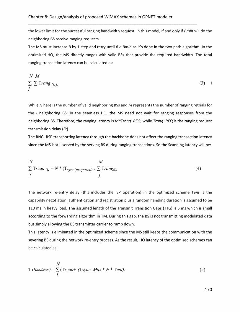
Chapter 8: Design/analysis of proposed WiMAX schemes in OPNET modeler ________________________________________________________________________
170
the lower limit for the successful ranging bandwidth request. In this model, if and only if Bmin >B, do the
neighboring BS receive ranging requests.
The MS must increase B by 1 step and retry until B ≥ Bmin as it’s done in the two path algorithm. In the
optimized HO, the MS directly ranges with valid BSs that provide the required bandwidth. The total
ranging transaction latency can be calculated as:
N M ∑ ∑ Trang (i, j) (3) i j
While N here is the number of valid neighboring BSs and M represents the number of ranging retrials for
the i neighboring BS. In the seamless HO, the MS need not wait for ranging responses from the
neighboring BS. Therefore, the ranging latency is M*Trang_REQ, while Trang_REQ is the ranging request
transmission delay (Ft).
The RNG_RSP transporting latency through the backbone does not affect the ranging transaction latency
since the MS is still served by the serving BS during ranging transactions. So the Scanning latency will be:
N M ∑ Tscan (i) = N * (Tsync(proposed) + ∑ Trang(j)) (4) i j
The network re-entry delay (this includes the ISP operation) in the optimized scheme Tent is the
capability negotiation, authentication and registration plus a random handling duration is assumed to be
110 ms in heavy load. The assumed length of the Transmit Transition Gaps (TTG) is 5 ms which is small
according to the forwarding algorithm in TM. During this gap, the BS is not transmitting modulated data
but simply allowing the BS transmitter carrier to ramp down.
This latency is eliminated in the optimized scheme since the MS still keeps the communication with the
severing BS during the network re-entry process. As the result, HO latency of the optimised schemes can
be calculated as:
N T (Handover) = ∑ (Tscan+ (Tsync_Max * N * Tent)) (5) i

Chapter 8: Design/analysis of proposed WiMAX schemes in OPNET modeler ________________________________________________________________________
171
8.4 Simulation Results
8.4.1 Scanning Modes
To discover the effects of traffic different types which have been applied in the network, firstly, we are
going to look at a light traffic and at a dense traffic networks and see the effects of the different
parameters applied at the nodes. The objective of the two scenarios is to show how different channel
conditions settings may affect application throughput.
These are the scanning interval definitions for both scenarios:
Table 8-1: Scanning Interval Definitions
Scanning Interval Activity: Indicates the current state of the scanning mode for this MS node:
-Interleaving duration (regular operation while scanning mode is on)
-Scanning duration (MS is scanning neighbour BSs while scan mode is on)
We run the OPNET simulations (for 3 and 15 minutes) to analysis the effects of different parameters on
the HO latency for both scenarios respectively. The achievement based on a comparison between our
proposals and the WiMAX standard handover scheme.
8.4.2 The Handover Delay (Sec)
The delay is a function of handover algorithm and traffic characteristics. Fast Channel Scanning (FCS)
scheme resulted in less delay as shown in figure 8-7.

Chapter 8: Design/analysis of proposed WiMAX schemes in OPNET modeler ________________________________________________________________________
172
Figure 8-7: Handover Delay
Handover delay is computed from the time the mobile station sends a MOB_MSHO-REQ message
starting the handover process until initial ranging with the new Serving BS is successfully completed.
The analysis results show that the FCS scheme as compared to the known Standard scheme can reduce
the scan time, therefore total handover latency up to 70% in the network topology acquisition process
especially in association modes and successfully keeps handover delay under 40 ms which is an optimal
result. The reduction comes from firstly, the elimination of network unnecessary BSs by performing
negotiations with neighboring BSs prior to scanning. Only selected BSs will be scanned and ranged
within the network. This ultimately reduces number of scans, thus the suspension of data transmission.
Secondly, from the intelligent channel selection based on transmission to another interface algorithm,
coding technique and other PHY/MAC entities.
Therefore, the total handover delay for both combined schemes shown in figure 8-8.

Chapter 8: Design/analysis of proposed WiMAX schemes in OPNET modeler ________________________________________________________________________
173
Figure 8-8: Total Handover Delay
8.4.3 FCS Throughput (Packets/sec)
The throughput result here is a function of handover algorithm and traffic characteristics, specifically to
Fast Channel Scanning (FCS) scheme. The application throughput shows that a more dense traffic may
reduce the application throughput. This should be expected since the WiMAX MAC will be "blocked"
more often while it is scanning neighbour BSs.

Chapter 8: Design/analysis of proposed WiMAX schemes in OPNET modeler ________________________________________________________________________
174
Figure 8-9: FCS, Fast Channel Scanning Throughput
8.4.4 Data Dropped During Handover (Packets/sec)
Data dropped (Packets/sec), this statistic records the uplink packets dropped (Packets/second) due to
physical layer impairments. At the MS side, this statistic represents the bit drops measured at a BS for all
packets arriving from a particular MS.
At the BS, this statistic represents the bits drops measured at the BS for all packets arriving from all SS
nodes in the cell/sector.
The Traffic Manager (TM) has successfully reduced the data dropped to 60% as shown in figure 8-10.
This means the congestion issue impact has been withdrawn.
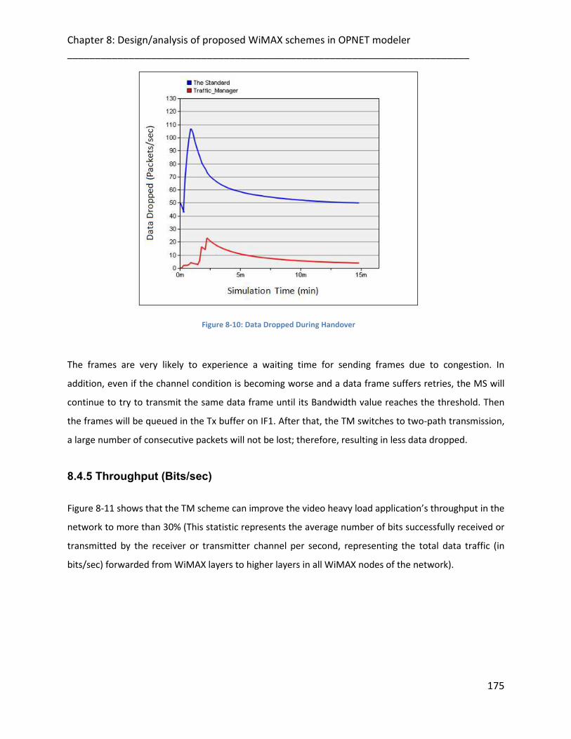
Chapter 8: Design/analysis of proposed WiMAX schemes in OPNET modeler ________________________________________________________________________
175
Figure 8-10: Data Dropped During Handover
The frames are very likely to experience a waiting time for sending frames due to congestion. In
addition, even if the channel condition is becoming worse and a data frame suffers retries, the MS will
continue to try to transmit the same data frame until its Bandwidth value reaches the threshold. Then
the frames will be queued in the Tx buffer on IF1. After that, the TM switches to two-path transmission,
a large number of consecutive packets will not be lost; therefore, resulting in less data dropped.
8.4.5 Throughput (Bits/sec)
Figure 8-11 shows that the TM scheme can improve the video heavy load application’s throughput in the
network to more than 30% (This statistic represents the average number of bits successfully received or
transmitted by the receiver or transmitter channel per second, representing the total data traffic (in
bits/sec) forwarded from WiMAX layers to higher layers in all WiMAX nodes of the network).

Chapter 8: Design/analysis of proposed WiMAX schemes in OPNET modeler ________________________________________________________________________
176
Figure 8-11: TM, Traffic Manager Throughput
In addition, results show when the MS handovers and switch to two paths transmission method, it can
still use the serving BS for communication so the handover has the less impact. Which may differs when
the data communication of a normal handover is cut with communicating BS.
8.4.6 Video Application End-to-End Delay (Sec)
The reduction of the video application’s packet end-to-end delay for the traffic received has reached to
more than 50% by the target node as shown in figure 8-12.
(This statistic represents the time elapsed between a packets is sent out by a video called party to the
time the packet reaches a video calling party. This statistic is collected on a caller basis). It represents
the time taken to send a video application packet to a destination node upper layer.

Chapter 8: Design/analysis of proposed WiMAX schemes in OPNET modeler ________________________________________________________________________
177
Figure 8-12: Video Application End-to-End Delay
In the simulation model, the delay to the CN from the TM is smaller than that from the known handover
method. Therefore, a packet sent immediately after the start of two-path transmission can arrive at the
CN safer than packets sent just before the start of two-path transmission.
8.4.7 Video Conferencing Average Response Time (Sec)
From figure 8-13, it can be seen that the proposed handover algorithm improved the system efficiency
and enhanced the overall network performance enormously in terms of fast application response time
of Video Conferencing applications (As the video Conferencing application enable users to transfer
streaming video frames across the network, which represents Time between frames generated within a
session from the source to the destination.) in response time are 70% respectively as compared to
Standard handover technique for WiMAX integrated networks. This statistic records data from all the
nodes in the network.

Chapter 8: Design/analysis of proposed WiMAX schemes in OPNET modeler ________________________________________________________________________
178
Figure 8-13: Video Conferencing Average Response Time
8.4.8 Traffic received (Packets/sec)
Traffic received represents by the correspondent node’s WiMAX MAC from the physical layer computed
in packets /sec.
The result shows the data traffic successfully received by the target node (This statistic represents the
total number of data packets received per second by target node from the network, across all
interfaces) and its improvement has reached to more than 60% in comparison to the known scheme.

Chapter 8: Design/analysis of proposed WiMAX schemes in OPNET modeler ________________________________________________________________________
179
Figure 8-14: Traffic received
The advantage of our cross-layer scheme is that the Performance does not degrade when the load
increases, as the load will be distributed across different channels. In a word, these fast handover
schemes can successfully reduce the waste of wireless resources and improve the throughput
performance of IEEE 802.16 broadband wireless networks and its mobility requirement during the
handover process.
8.4.9 Queue size (packets)
Represents the total number packets in MAC's transmission queue(s). Normally, the queue(s) will only
contain data packets of the higher layer. (TM_MAC_PDU) frames that are explicitly modeled in this
proposal will be also included in this statistic when they are queued for transmission.

Chapter 8: Design/analysis of proposed WiMAX schemes in OPNET modeler ________________________________________________________________________
180
Figure 8-15: Queue Size
In the MAC layer of the BS, the queue size represented by this statistic also includes the frames that are
received from physical layer and awaiting being forwarded to their final destination within the BS. The
total number of the frames in MAC/PHY queues.
When they require an ACK, data and (TM_MAC_PDU) frames will be removed from the transmission
queue(s) only when their ACK is received or when they are discarded due to consistent retransmission
failures and reaching retry limit.
8.4.10 Media Access Delay (sec)
As it is obvious from Figure 8-16, TM has the lower media access delay as route discovery mechanism is
performed trying to find the optimum path available. The standard scheme had an increase of 20%. This
can be given credit to the optimisation from the proposed scheme.

Chapter 8: Design/analysis of proposed WiMAX schemes in OPNET modeler ________________________________________________________________________
181
Figure 8-16: Media Access Delay
8.5 Summary
Table 7-2, provides a comparison of various features between the proposed schemes and the WiMAX
standard scheme. The analysis presented throughout this chapter establishes the key fact that proposed
schemes outperforms the existing scheme in terms of several network performance matrices and in
diverse range of scenarios. Proposed schemes specially perform better in scenarios with high mobility.
Although it has to be noted that proposed schemes has a very adaptive nature because of the route
parameters and Interface algorithm. Thus the parameters can be set in such a way as to obtain the
optimum performance of the network depending on the scenario that it is being adopted by.

Chapter 8: Design/analysis of proposed WiMAX schemes in OPNET modeler ________________________________________________________________________
182
Table 8-2: Comparison of Various Features between the Proposed Schemes and the WiMAX Standard Scheme
8.6 References
[1] OPNET Modeler, OPNET Technologies Incorporation. www.opnet.com.
[2] Optimized Network Engineering Tools, OPNET Technologies, and session 1827, available on:
www.opnet.com, 2007.

________________________________________________________________________
9
Chapter 9183
CONCLUSION AND FUTURE WORK
9.1 Conclusion
First, this thesis gives some brief introduction about the new technology that is used everywhere and for
everybody ubiquitously. Likewise are presented wireless networks and how they are becoming
increasingly popular in the communication industry and one of the most significant technology
breakthroughs among all human achievements in the past few decades.
The first part of the chapter 2 navigates through the recent developments in WLAN and WiMAX.
However, a classification on the basis of communication procedure (single-home/multi-home), topology,
(node configuration) and network size (in terms of coverage area and number of devices defined with
examples.
The second part of chapter 2, introduces the Worldwide Interoperability for Microwave Access
(WiMAX). The IEEE Standards Board established the IEEE 802.16 Working Group in 1999. Mobile WiMAX
standard provides Quality of Service by using several techniques; reside at both physical and MAC layers.
Descriptions of these techniques are highlighted in this chapter. Finally, the last section of this chapter
shows how the Mobile WiMAX is able to support mobility with high speed user, through supporting
seamless handover to enable the mobile user to switch from one base station to another at vehicular
speeds.
The published work for related work and the multihoming protocols are described in detail, which are
different in their approach used for route path discovery, maintaining the existing routes in case of link
failures or the movement of nodes away from the existing networks. Likewise, the operation and routing
mechanism for well-known multihoming protocols such as MIPv6, SCTP, NEMO, HIP and Shim6 are
presented. The most related work in handover and cross layer researches presented with respect to the
proposed work. Finally, Handover Performance Requirements concludes the first part of chapter 3.
________________________________________________________________________
184
Various aspects of the Interface Selection Protocol (ISP) protocol are presented in detail such as the
routing path process, route maintenance, packets format for Probe message and route parameters used
within route path discovery. Likewise, the implementation and modelling framework used for simulation
purposes of ISP, which is based on a cross-layer information exchange is also explained in detail. All of
this has been explored and described earlier in chapter 4.
Chapter 5 which has been explored deeply, consists of two parts, the first part explains the model design
in detail, some basic detail on the actual simulation program designed in OPNET Modeler. The second
part describes the ISP model in OPNET modeller 14.0. Part two provides a small introduction on ISP. Also
it describes the node design in great detail with respect to the ISP node operation, simulation
parameters and testing. Then a discussion follows involving the adaptation of the ISP principles in a
wireless node as presented in OPNET Modeler. The newly introduced simulation parameters together
with all the old parameters provided by the wireless node in OPNET Modeler is identified and explained.
Finally this chapter involves proof of operation of the model and how a user can setup a fully
operational ISP project for investigating the performance of the ISP protocol.
Chapter 6 provides the simulation results and scenarios along with a comprehensive study of the well
known multihoming protocols e.g. MIPv6 and Shim6 using OPNET version 14.00. First section explains
the simulation environment in detail such as the type of the network, and type of traffic that is sent
from the source to the destination. This section presents the evaluation parameters that are used and
measured in the different multihoming protocols.
The second section presents the ISP results that show the adaptability of the protocol and also shows
the route parameters for different scenarios. The third section shows full comparison of ISP with two
different well known multihoming protocols such as MIPv6 and Shim6. The comparison covers most of
the real life scenarios such as the different type of the networks (small, large). In other words, the
performance of the protocol is analyzed according to varying node density, mobility patterns (high/low
mobility) and varying types of application generated traffic (delay sensitive real time traffic and non real
time traffic).
In the end, a comparison of various features between ISP, MIPv6 and
Shim6 is provided. The analysis presented throughout this chapter establishes the key fact that ISP
outperforms most of the existing multihoming protocols in terms of several network performance

________________________________________________________________________
185
metrics in diverse range of WLAN scenarios. ISP specially performs better in scenarios with larger device
density and with high mobility. In these particular conditions it has also been observed that ISP has a
very good response and improved performance. There might be a case where MIPv6 can be considered
as a better choice for the protocol. Although it has to be noted that ISP has a very adaptive nature
because of the route parameters. Thus the parameters can be set in such a way as to obtain the
optimum performance of the network depending on the scenario that it is being adopted by. Finally
Shim6 is seen to be a good choice as compared with ISP in small fixed networks with low traffic load.
Chapter 7 describes the proposed schemes in the WiMAX network. These schemes are new reliable
handover schedules, which are essentially succession of wireless interface switching criterions. They are
able to provide a reliable communication route with assurance of good bandwidth (data-rate), lower
handover latency and route path optimization. The design of the schemes is based on a novel cross layer
information exchange mechanism which enables to use various network related parameters from
different layers (Link/ Physical layers) across the protocol suite for decision making at the Network layer.
The first solution, Fast Channel Scanning (FCS), has been proposed. Its solution was to improve the
mobile WiMAX handover and address the scanning latency. Since minimum scanning time is the most
important issue in the handover process. This handover scheme aims to utilize the channel efficiently
and apply such a procedure so as to reduce the time it takes to scan the neighboring base stations. This
implies that the un-necessary scanning of neighboring base stations should be avoided by reducing the
number of base stations to be scanned by performing negotiation prior to scanning. The second
solution, Traffic Manager (TM) is to adapt the channel congestion problem and how it severely restricts
the amount of critical video streams, introducing an algorithm that based on the channel bandwidth
information, and assigning different channel for each connection. The core idea is that when an MS is
transmitting a video application through the wireless channel to the serving BS, and this channel
capacity is over loaded, this will enhance MS to try to find an alternative path to forward the additional
application streams, so the different video packets can be transmitted in different bit-streams in
different channels and this happens with an intelligent use of video coding technique. This dilemma use
case led to the development of our Traffic Manager (TM).
In chapter 8, the WiMAX proposal implemented on OPNET v.14 is explained. In the first part of the
chapter, WiMAX node design is presented with relevant attributes for the nodes. Also how the network
settings for the transmitter nodes and data packets operation will be presented in details. The chapter’s
second part, a complete simulation result and analysis/discussion is presented with relevant graphs and

________________________________________________________________________
186
tables. Furthermore an inclusive comparison is made to determine optimal performance. The analysis
presented throughout this chapter establishes the key fact that the proposed schemes outperform the
existing WiMAX handover scheme in terms of several network performance metrics in diverse range of
scenarios.
The goal of this thesis has been to use route parameter (bandwidth and delay) for developing efficient
and reliable protocols for multi-homed networks. Also the cross layer technique is used to integrate
between the application, PHY/MAC and Network layer to connect layers to make decisions to find the
optimum path based on the information. Firstly, ISP considers route parameters during new path
discovery and an optimum path is selected as a result which meets the source node requirements level.
Likewise ISP provides flexibility and the default route selection parameters can be overridden with
custom parameters specified according to the application requirements. The overview of the ISP routing
discovery algorithm to find the best bath and alternative path for the protocol depends on route
parameters information. The operation of searching the optimum path for ISP starts when the source
node broadcasts Probe message to the destination nodes to calculate and chooses the optimum path
between the two nodes. Secondly, the FCS and TM schemes which are able to provide a reliable
communication route with assurance of good bandwidth (data-rate), lower handover latency and route
path optimization. The design of the schemes is based on a novel cross layer information exchange
mechanism which enables to use various network related parameters from different layers (Link/
Physical layers) across the protocol suite for decision making at the Network layer.

________________________________________________________________________
187
9.2 FUTURE WORK
One of the important portions of future work is to develop a version of ISP that can work perfectly and
scale to all types of networks. ISP finds the path based on two route parameters but my suggestion to
the researchers who are interested in ISP is to increase the route parameters by making the node more
robust in other parameters to find the optimum path from the source to destination node. Also my
suggestion to the researcher who which interested for ISP protocol to make the protocol secured by
adding some key encrypted during the routing discovery process, likewise the intelligent function that
help the protocol to work with more scenarios and interfaces, finally the optimization aspect also should
be developed further.
Future work, will aim to convert the TM server scheme to a protocol design that will add more
applications in addition to video traffic in large mesh networks, to improve the system scalability and
other capacity issues of the network. Since the proposed traffic management scheme had MS equipped
with two WiMAX interfaces that is impractical as it will increase the hardware cost of MSs If an intention
to bring this product/service to market.

________________________________________________________________________
188
List of publications
Accepted papers:
1. Z. Jerjees and H. Al-Raweshidy, “A Novel Mechanism to Switch Between Multi-homed MIPv6
Networks”, in the proceeding of MIC-CCA, WCMC, Wireless Communications and Mobile
Computing. 1 May 2008.
2. Z. Jerjees and H. Al-Raweshidy, “A Novel Mechanism to Select Better Multi-homed MIPv6
Networks”, In the Proceedings of the 2008 Second International Conference on Next
Generation Mobile Applications , Services, and Technologies(NGMAST 2008), Cardiff, UK,
Sept. 2008.
3. Zina Jerjees, Omar Raoof and H.S. Al-Raweshidy, “Cross-layer Optimization And Handover
Managements In Next Generation Mobile Networks”, the Fifth international Conference on
Broadband Communications, Networks and Systems (BROADNETS) September 8-11, 2008,
London, UK.
4. Z. Jerjees, H.S. Al-Raweshidy, “Optimized Handover Scheme In Multi-homed MIPv6
Networks”, 16th International Conference on Telecommunications ICT - Communication
Networks & Management. 11 March 2009.
5. Z. Jerjees, H.S. Al-Raweshidy and O. Raoof, “Cross Layer Design to Improve the Handover
Latency In Multi-homed WLANs”, In the Fifth IEEE GCC Communications and Signal Processing
Conference, Kuwait, Mar. 2009
6. O. Raoof, H. Radi, H.S. Al- Raweshidy and Zina Jerjees, “Dynamic Interface/Network Selection
Mechanism approach for Multi-homed Wireless Nodes”. Fifth IEEE GCC conference. 17-19
March 2009.
7. Zina Jerjees, H. Al-Raweshidy and Zaineb Al-Banna, "Optimized Handover Schemes over
WiMAX". Second Joint IFIP WMNC conference, Sept. 2009.
8. Zina Jerjees and H. Al-Raweshidy,"Optimized Handover Management Schemes for Mobile
WiMAX". In the Proceedings of the 2009 Third International Conference on Next Generation
Mobile Applications , Services, and Technologies(NGMAST 2008), Cardiff, UK, Sept. 2009

________________________________________________________________________
189
Book Chapter:
Z. Jerjees; H. S. Al-Raweshidy and Z. Al-Banna; "Optimized Handover Schemes over WiMAX ", a book
titled: 'Wireless and Mobile Networking', published by Springer Boston (Computer Science), ISBN 978-3-
642-03840-2, 31 August 2009.
Papers currently under-review:
1. Z. Jerjees and H. Al-Raweshidy, “Scalable Handover Design for Video Applications in WiMAX”,
IET Communications, 2010.
2. Zina Jerjees, H. Al-Raweshidy, “Traffic Management for Video Applications in WiMAX”, IEEE
Transactions on Wireless Communications, 2010.


![01 01 RN33021EN20GLA0 RAN Interface and Protocols [Compatibility Mode]](https://img.pdfslide.us/doc/110x75/577cc3b11a28aba71196e1bf/01-01-rn33021en20gla0-ran-interface-and-protocols-compatibility-mode.jpg)