Embed Size (px)
Citation preview
Design of Injection and Recombination in Quantum DotSensitized Solar Cells
Eva M. Barea,† Menny Shalom,‡ Sixto Gimenez,† Idan Hod,‡ Ivan Mora-Sero,*,†
Arie Zaban,‡ and Juan Bisquert†
PhotoVoltaic and Optoelectronic DeVices Group, Departament de Fısica, UniVersitat Jaume I,12071 Castello, Spain and Institute of Nanotechnology & AdVanced Materials, Deptartment of
Chemistry, Bar Ilan UniVersity, 52900 Ramat Gan, Israel
Received March 2, 2010; E-mail: [email protected]
Abstract: Semiconductor Quantum Dots (QDs) currently receive widespread attention for the developmentof photovoltaic devices due to the possibility of tailoring their optoelectronic properties by the control ofsize and composition. Here we show that it is possible to design both injection and recombination in QDsensitized solar cells (QDSCs) by the appropriate use of molecular dipoles and conformal coatings. QDSCshave been manufactured using mesoporous TiO2 electrodes coated with “in situ” grown CdSe semiconductornanocrystals by chemical bath deposition (CBD). Surface modification of the CdSe sensitized electrodesby conformal ZnS coating and grafting of molecular dipoles (DT) has been explored to both increase theinjection from QDs into the TiO2 matrix and reduce the recombination of the QD sensitized electrodes.Different sequences of both treatments have been tested aiming at boosting the energy conversion efficiencyof the devices. The obtained results showed that the most favorable sequence of the surface treatment(DT+ZnS) led to a dramatic 600% increase of photovoltaic performance compared to the reference electrode(without modification): Voc ) 0.488 V, jsc ) 9.74 mA/cm2, FF ) 0.34, and efficiency ) 1.60% under full 1sun illumination. The measured photovoltaic performance was correlated to the relative position of theCdSe conduction band (characterized by surface photovoltage measurements) and TiO2 conduction band(characterized by the chemical capacitance, Cµ) together with recombination resistance, Rrec.
1. Introduction
Quantum dot sensitized solar cells (QDSCs) constitute oneof the most promising low cost candidates for third generationphotovoltaics.1-4 This solar cell concept is borrowed from thephotoelectrochemical Gratzel’s cell, the dye sensitized solar cell(DSC),5 which is based on a mesoporous structure of a wideband semiconductor material (e.g., TiO2, ZnO...) sensitized bya light harvesting material (conventionally metallorganic Ru-based dyes), permeated with a redox electrolyte, and sandwichedby a counterelectrode. The formal difference between QDSCsand DSCs relies on the use of semiconductor nanocrystals (QDs)instead of dyes as light absorber materials. QDs exhibit severaladvantages with respect to metallorganic dyes as light absorbersrelated to tunable band gaps by size control,6 higher molarextinction coefficients,7 and large intrinsic dipole moments8,9
enhancing charge separation. However, at present, the record
solar conversion efficiencies of QDSCs (3-4%)10,11 lag behindDSCs (11.4%)12 by a factor of 3-4, although progressiveoptimization of the former is expected to narrow the actual gap.
The replacement of the light harvesting material in the solarcell configuration requires a full modification process involvinga general substitution of the other components to preserve thefavorable band alignment for charge separation, charge transferprocesses, and QD stability.13,14 Additionally, the competitionbetween injection, transport, and recombination kinetics mustremain favorable for efficient conversion efficiency together withchemical compatibility of the full device. As an example, thestandard I-/I3
- redox couple employed for DSCs is notchemically compatible with QDs leading to fast degradation ofthe nanocrystals. Consequently, nanometric barriers betweenQDs and electrolyte must be included15,16 to maintain chemicalcompatibility, or alternatively, different redox systems must be
† Universitat Jaume I.‡ Bar Ilan University.
(1) Nozik, A. J. Physica E 2002, 14, 115.(2) Klimov, V. I. J. Phys. Chem. B 2006, 110, 16827.(3) Kamat, P. V. J. Phys. Chem. C 2008, 112, 18737.(4) Hodes, G. J. Phys. Chem. C 2008, 112, 17778.(5) O’Regan, B.; Gratzel, M. Nature 1991, 353, 737.(6) Yu, W.; Qu, L. H.; Guo, W. Z.; Peng, X. G. Chem. Mater. 2003, 15,
2854.(7) Wang, P.; Zakeeruddin, S. M.; Moser, J. E.; Humphry-Baker, R.;
Comte, P.; Aranyos, V.; Hagfeldt, A.; Nazeeruddin, M. K.; Gratzel,M. AdV. Mater. 2004, 16, 1806.
(8) Vogel, R.; Hoyer, P.; Weller, H. J. Phys. Chem. B 1994, 98, 3183.(9) Vogel, R.; Pohl, K.; Weller, H. Chem. Phys. Lett. 1990, 174, 241.
(10) Diguna, L. J.; Shen, Q.; Kobayashi, J.; Toyoda, T. Appl. Phys. Lett.2007, 91, 0231161.
(11) Fan, S.-Q.; Fang, B.; Kim, J. H.; Kim, J.-J.; Yu, J.-S.; Ko, J. Appl.Phys. Lett. 2010, 96, 063501.
(12) Cao, Y.; Bai, Y.; Yu, Q.; Cheng, Y.; Liu, S.; Shi, D.; Gao, F.; Wang,P. J. Phys. Chem. C 2009, 113, 6290.
(13) Mora-Sero, I.; Gimenez, S.; Fabregat-Santiago, F.; Gomez, R.; Shen,Q.; Toyoda, T.; Bisquert, J. Acc. Chem. Res. 2009, 42, 1848.
(14) Lee, H. J.; Yum, J.-H.; Leventis, H. C.; Zakeeruddin, S. M.; Haque,S. A.; Chen, P.; Seok, S. I.; Gratzel, M.; Nazeeruddin, M. K. J. Phys.Chem. C 2008, 112, 11600.
(15) Shalom, M.; Dor, S.; Ruhle, S.; Grinis, L.; Zaban, A. J. Phys. Chem.C 2009, 113, 3895.
(16) Shalom, M.; Albero, J.; Tachan, Z.; Martınez-Ferrero, E.; Zaban, A.;Palomares, E. J. Phys. Chem. Lett. 2010, 1, 1134.
Published on Web 04/28/2010
10.1021/ja101752d 2010 American Chemical Society6834 9 J. AM. CHEM. SOC. 2010, 132, 6834–6839
incorporated as the polysulfide17-19 or Co-based14,20 systems.Moreover, the electrocatalytic activity of the Pt counterelectrodesconventionally used for DSCs is poor17,21,22 and thus unable toregenerate the polysulfide electrolyte leading to high seriesresistances, and more suitable materials should be employed(Au, Cu2S, CoS, etc.).11,17,22,23
On the other hand, surface modification via different ap-proaches has demonstrated to be a powerful tool to boost theenergy conversion efficiencies of the devices. For example,tailoring the band alignment of wide band semiconductors asTiO2 and CdS semiconductor nanocrystals through surfacemodification with molecular dipoles24 leads to a significantincrease in energy conversion efficiency in QDSCs. Addition-ally, coating the TiO2/CdSe nanoporous structure with ZnSnanometric barriers23,25 results in almost doubling the efficiencyof these solar cells mainly due to a significant increase of therecombination resistance between TiO2 and the electrolyte.13
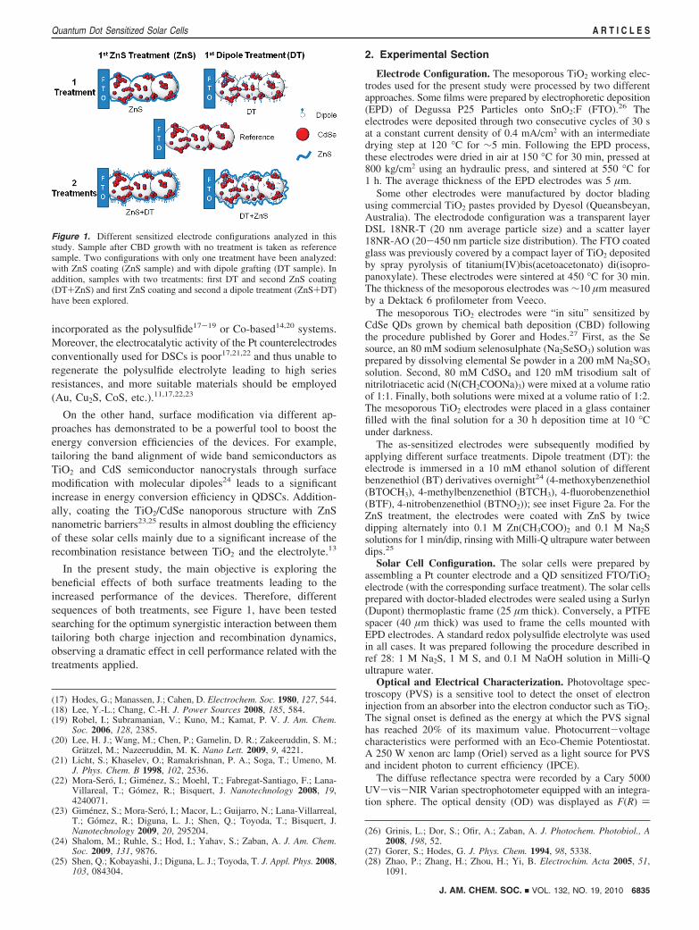
In the present study, the main objective is exploring thebeneficial effects of both surface treatments leading to theincreased performance of the devices. Therefore, differentsequences of both treatments, see Figure 1, have been testedsearching for the optimum synergistic interaction between themtailoring both charge injection and recombination dynamics,observing a dramatic effect in cell performance related with thetreatments applied.
2. Experimental Section
Electrode Configuration. The mesoporous TiO2 working elec-trodes used for the present study were processed by two differentapproaches. Some films were prepared by electrophoretic deposition(EPD) of Degussa P25 Particles onto SnO2:F (FTO).26 Theelectrodes were deposited through two consecutive cycles of 30 sat a constant current density of 0.4 mA/cm2 with an intermediatedrying step at 120 °C for ∼5 min. Following the EPD process,these electrodes were dried in air at 150 °C for 30 min, pressed at800 kg/cm2 using an hydraulic press, and sintered at 550 °C for1 h. The average thickness of the EPD electrodes was 5 µm.
Some other electrodes were manufactured by doctor bladingusing commercial TiO2 pastes provided by Dyesol (Queansbeyan,Australia). The electrodode configuration was a transparent layerDSL 18NR-T (20 nm average particle size) and a scatter layer18NR-AO (20-450 nm particle size distribution). The FTO coatedglass was previously covered by a compact layer of TiO2 depositedby spray pyrolysis of titanium(IV)bis(acetoacetonato) di(isopro-panoxylate). These electrodes were sintered at 450 °C for 30 min.The thickness of the mesoporous electrodes was ∼10 µm measuredby a Dektack 6 profilometer from Veeco.
The mesoporous TiO2 electrodes were “in situ” sensitized byCdSe QDs grown by chemical bath deposition (CBD) followingthe procedure published by Gorer and Hodes.27 First, as the Sesource, an 80 mM sodium selenosulphate (Na2SeSO3) solution wasprepared by dissolving elemental Se powder in a 200 mM Na2SO3
solution. Second, 80 mM CdSO4 and 120 mM trisodium salt ofnitrilotriacetic acid (N(CH2COONa)3) were mixed at a volume ratioof 1:1. Finally, both solutions were mixed at a volume ratio of 1:2.The mesoporous TiO2 electrodes were placed in a glass containerfilled with the final solution for a 30 h deposition time at 10 °Cunder darkness.
The as-sensitized electrodes were subsequently modified byapplying different surface treatments. Dipole treatment (DT): theelectrode is immersed in a 10 mM ethanol solution of differentbenzenethiol (BT) derivatives overnight24 (4-methoxybenzenethiol(BTOCH3), 4-methylbenzenethiol (BTCH3), 4-fluorobenzenethiol(BTF), 4-nitrobenzenethiol (BTNO2)); see inset Figure 2a. For theZnS treatment, the electrodes were coated with ZnS by twicedipping alternately into 0.1 M Zn(CH3COO)2 and 0.1 M Na2Ssolutions for 1 min/dip, rinsing with Milli-Q ultrapure water betweendips.25
Solar Cell Configuration. The solar cells were prepared byassembling a Pt counter electrode and a QD sensitized FTO/TiO2
electrode (with the corresponding surface treatment). The solar cellsprepared with doctor-bladed electrodes were sealed using a Surlyn(Dupont) thermoplastic frame (25 µm thick). Conversely, a PTFEspacer (40 µm thick) was used to frame the cells mounted withEPD electrodes. A standard redox polysulfide electrolyte was usedin all cases. It was prepared following the procedure described inref 28: 1 M Na2S, 1 M S, and 0.1 M NaOH solution in Milli-Qultrapure water.
Optical and Electrical Characterization. Photovoltage spec-troscopy (PVS) is a sensitive tool to detect the onset of electroninjection from an absorber into the electron conductor such as TiO2.The signal onset is defined as the energy at which the PVS signalhas reached 20% of its maximum value. Photocurrent-voltagecharacteristics were performed with an Eco-Chemie Potentiostat.A 250 W xenon arc lamp (Oriel) served as a light source for PVSand incident photon to current efficiency (IPCE).
The diffuse reflectance spectra were recorded by a Cary 5000UV-vis-NIR Varian spectrophotometer equipped with an integra-tion sphere. The optical density (OD) was displayed as F(R) )
(17) Hodes, G.; Manassen, J.; Cahen, D. Electrochem. Soc. 1980, 127, 544.(18) Lee, Y.-L.; Chang, C.-H. J. Power Sources 2008, 185, 584.(19) Robel, I.; Subramanian, V.; Kuno, M.; Kamat, P. V. J. Am. Chem.
Soc. 2006, 128, 2385.(20) Lee, H. J.; Wang, M.; Chen, P.; Gamelin, D. R.; Zakeeruddin, S. M.;
Gratzel, M.; Nazeeruddin, M. K. Nano Lett. 2009, 9, 4221.(21) Licht, S.; Khaselev, O.; Ramakrishnan, P. A.; Soga, T.; Umeno, M.
J. Phys. Chem. B 1998, 102, 2536.(22) Mora-Sero, I.; Gimenez, S.; Moehl, T.; Fabregat-Santiago, F.; Lana-
Villareal, T.; Gomez, R.; Bisquert, J. Nanotechnology 2008, 19,4240071.
(23) Gimenez, S.; Mora-Sero, I.; Macor, L.; Guijarro, N.; Lana-Villarreal,T.; Gomez, R.; Diguna, L. J.; Shen, Q.; Toyoda, T.; Bisquert, J.Nanotechnology 2009, 20, 295204.
(24) Shalom, M.; Ruhle, S.; Hod, I.; Yahav, S.; Zaban, A. J. Am. Chem.Soc. 2009, 131, 9876.
(25) Shen, Q.; Kobayashi, J.; Diguna, L. J.; Toyoda, T. J. Appl. Phys. 2008,103, 084304.
(26) Grinis, L.; Dor, S.; Ofir, A.; Zaban, A. J. Photochem. Photobiol., A2008, 198, 52.
(27) Gorer, S.; Hodes, G. J. Phys. Chem. 1994, 98, 5338.(28) Zhao, P.; Zhang, H.; Zhou, H.; Yi, B. Electrochim. Acta 2005, 51,
1091.
Figure 1. Different sensitized electrode configurations analyzed in thisstudy. Sample after CBD growth with no treatment is taken as referencesample. Two configurations with only one treatment have been analyzed:with ZnS coating (ZnS sample) and with dipole grafting (DT sample). Inaddition, samples with two treatments: first DT and second ZnS coating(DT+ZnS) and first ZnS coating and second a dipole treatment (ZnS+DT)have been explored.
J. AM. CHEM. SOC. 9 VOL. 132, NO. 19, 2010 6835
Quantum Dot Sensitized Solar Cells A R T I C L E S
(1 - R)2/2R in Kubelka-Munk units, where R is the measureddiffuse reflectance. Current-potential curves and impedance spec-troscopy measurements were obtained using an FRA equippedPGSTAT-30 from Autolab. The cells were illuminated using a solarsimulator at AM 1.5 G, where the light intensity was adjusted withan NREL-calibrated Si solar cell with a KG-5 filter to a 1 sunintensity (100 mW cm-2). Impedance spectroscopy (IS) measure-ments were carried out in dark conditions at forward bias: 0-0.5V, applying a 20 mV AC sinusoidal signal over the constant appliedbias with the frequency ranging between 500 kHz and 0.1 Hz.
3. Results and Discussion
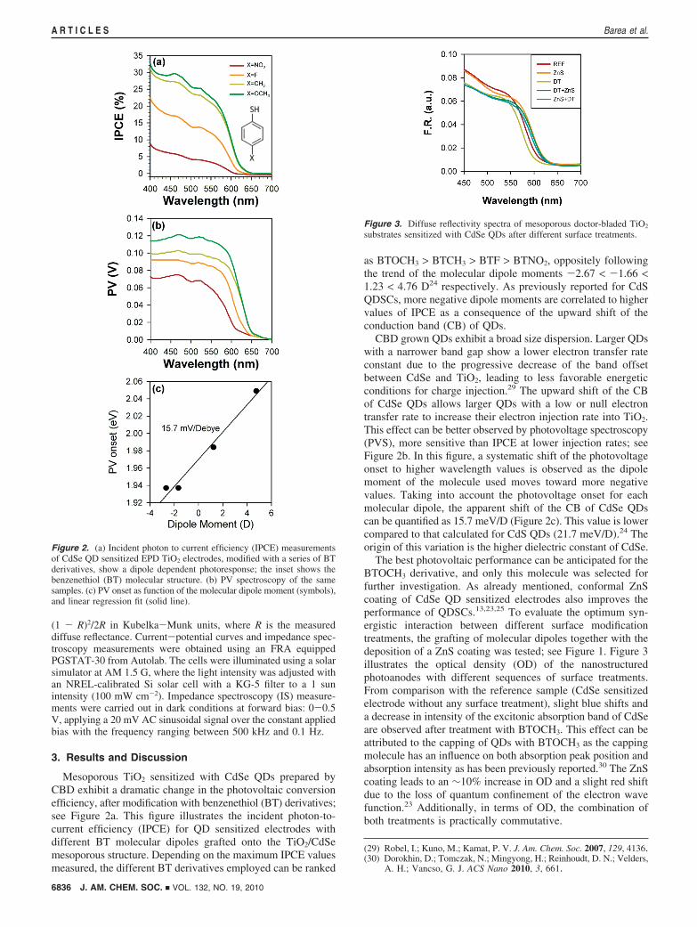
Mesoporous TiO2 sensitized with CdSe QDs prepared byCBD exhibit a dramatic change in the photovoltaic conversionefficiency, after modification with benzenethiol (BT) derivatives;see Figure 2a. This figure illustrates the incident photon-to-current efficiency (IPCE) for QD sensitized electrodes withdifferent BT molecular dipoles grafted onto the TiO2/CdSemesoporous structure. Depending on the maximum IPCE valuesmeasured, the different BT derivatives employed can be ranked
as BTOCH3 > BTCH3 > BTF > BTNO2, oppositely followingthe trend of the molecular dipole moments -2.67 < -1.66 <1.23 < 4.76 D24 respectively. As previously reported for CdSQDSCs, more negative dipole moments are correlated to highervalues of IPCE as a consequence of the upward shift of theconduction band (CB) of QDs.
CBD grown QDs exhibit a broad size dispersion. Larger QDswith a narrower band gap show a lower electron transfer rateconstant due to the progressive decrease of the band offsetbetween CdSe and TiO2, leading to less favorable energeticconditions for charge injection.29 The upward shift of the CBof CdSe QDs allows larger QDs with a low or null electrontransfer rate to increase their electron injection rate into TiO2.This effect can be better observed by photovoltage spectroscopy(PVS), more sensitive than IPCE at lower injection rates; seeFigure 2b. In this figure, a systematic shift of the photovoltageonset to higher wavelength values is observed as the dipolemoment of the molecule used moves toward more negativevalues. Taking into account the photovoltage onset for eachmolecular dipole, the apparent shift of the CB of CdSe QDscan be quantified as 15.7 meV/D (Figure 2c). This value is lowercompared to that calculated for CdS QDs (21.7 meV/D).24 Theorigin of this variation is the higher dielectric constant of CdSe.
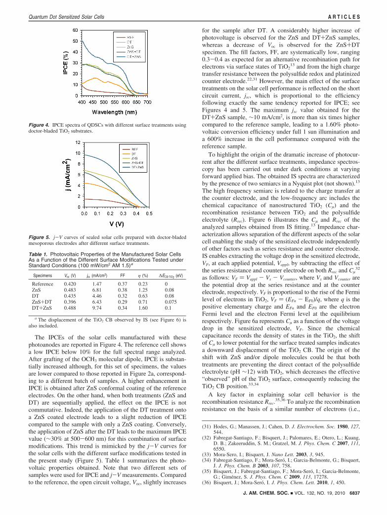
The best photovoltaic performance can be anticipated for theBTOCH3 derivative, and only this molecule was selected forfurther investigation. As already mentioned, conformal ZnScoating of CdSe QD sensitized electrodes also improves theperformance of QDSCs.13,23,25 To evaluate the optimum syn-ergistic interaction between different surface modificationtreatments, the grafting of molecular dipoles together with thedeposition of a ZnS coating was tested; see Figure 1. Figure 3illustrates the optical density (OD) of the nanostructuredphotoanodes with different sequences of surface treatments.From comparison with the reference sample (CdSe sensitizedelectrode without any surface treatment), slight blue shifts anda decrease in intensity of the excitonic absorption band of CdSeare observed after treatment with BTOCH3. This effect can beattributed to the capping of QDs with BTOCH3 as the cappingmolecule has an influence on both absorption peak position andabsorption intensity as has been previously reported.30 The ZnScoating leads to an ∼10% increase in OD and a slight red shiftdue to the loss of quantum confinement of the electron wavefunction.23 Additionally, in terms of OD, the combination ofboth treatments is practically commutative.
(29) Robel, I.; Kuno, M.; Kamat, P. V. J. Am. Chem. Soc. 2007, 129, 4136.(30) Dorokhin, D.; Tomczak, N.; Mingyong, H.; Reinhoudt, D. N.; Velders,
A. H.; Vancso, G. J. ACS Nano 2010, 3, 661.
Figure 2. (a) Incident photon to current efficiency (IPCE) measurementsof CdSe QD sensitized EPD TiO2 electrodes, modified with a series of BTderivatives, show a dipole dependent photoresponse; the inset shows thebenzenethiol (BT) molecular structure. (b) PV spectroscopy of the samesamples. (c) PV onset as function of the molecular dipole moment (symbols),and linear regression fit (solid line).
Figure 3. Diffuse reflectivity spectra of mesoporous doctor-bladed TiO2
substrates sensitized with CdSe QDs after different surface treatments.
6836 J. AM. CHEM. SOC. 9 VOL. 132, NO. 19, 2010
A R T I C L E S Barea et al.
The IPCEs of the solar cells manufactured with thesephotoanodes are reported in Figure 4. The reference cell showsa low IPCE below 10% for the full spectral range analyzed.After grafting of the OCH3 molecular dipole, IPCE is substan-tially increased although, for this set of specimens, the valuesare lower compared to those reported in Figure 2a, correspond-ing to a different batch of samples. A higher enhancement inIPCE is obtained after ZnS conformal coating of the referenceelectrodes. On the other hand, when both treatments (ZnS andDT) are sequentially applied, the effect on the IPCE is notcommutative. Indeed, the application of the DT treatment ontoa ZnS coated electrode leads to a slight reduction of IPCEcompared to the sample with only a ZnS coating. Conversely,the application of ZnS after the DT leads to the maximum IPCEvalue (∼30% at 500-600 nm) for this combination of surfacemodifications. This trend is mimicked by the j-V curves forthe solar cells with the different surface modifications tested inthe present study (Figure 5). Table 1 summarizes the photo-voltaic properties obtained. Note that two different sets ofsamples were used for IPCE and j-V measurements. Comparedto the reference, the open circuit voltage, Voc, slightly increases
for the sample after DT. A considerably higher increase ofphotovoltage is observed for the ZnS and DT+ZnS samples,whereas a decrease of Voc is observed for the ZnS+DTspecimen. The fill factors, FF, are systematically low, ranging0.3-0.4 as expected for an alternative recombination path forelectrons via surface states of TiO2
13 and from the high chargetransfer resistance between the polysulfide redox and platinizedcounter electrode.22,31 However, the main effect of the surfacetreatments on the solar cell performance is reflected on the shortcircuit current, jsc, which is proportional to the efficiencyfollowing exactly the same tendency reported for IPCE; seeFigures 4 and 5. The maximum jsc value obtained for theDT+ZnS sample, ∼10 mA/cm2, is more than six times highercompared to the reference sample, leading to a 1.60% photo-voltaic conversion efficiency under full 1 sun illumination anda 600% increase in the cell performance compared with thereference sample.
To highlight the origin of the dramatic increase of photocur-rent after the different surface treatments, impedance spectros-copy has been carried out under dark conditions at varyingforward applied bias. The obtained IS spectra are characterizedby the presence of two semiarcs in a Nyquist plot (not shown).13
The high frequency semiarc is related to the charge transfer atthe counter electrode, and the low-frequency arc includes thechemical capacitance of nanostructured TiO2 (Cµ) and therecombination resistance between TiO2 and the polysulfideelectrolyte (Rrec). Figure 6 illustrates the Cµ and Rrec of theanalyzed samples obtained from IS fitting.13 Impedance char-acterization allows separation of the different aspects of the solarcell enabling the study of the sensitized electrode independentlyof other factors such as series resistance and counter electrode.IS enables extracting the voltage drop in the sensitized electrode,VF, at each applied potential, Vappl, by subtracting the effect ofthe series resistance and counter electrode on both Rrec and Cµ
32
as follows: VF ) Vappl - Vs - Vcounter, where Vs and Vcounter arethe potential drop at the series resistance and at the counterelectrode, respectively. VF is proportional to the rise of the Fermilevel of electrons in TiO2, VF ) (EFn - EF0)/q, where q is thepositive elementary charge and EFn and EF0 are the electronFermi level and the electron Fermi level at the equilibriumrespectively. Figure 6a represents Cµ as a function of the voltagedrop in the sensitized electrode, VF. Since the chemicalcapacitance records the density of states in the TiO2, the shiftof Cµ to lower potential for the surface treated samples indicatesa downward displacement of the TiO2 CB. The origin of theshift with ZnS and/or dipole molecules could be that bothtreatments are preventing the direct contact of the polysulfideelectrolyte (pH ∼12) with TiO2, which decreases the effective“observed” pH of the TiO2 surface, consequently reducing theTiO2 CB position.33,34
A key factor in explaining solar cell behavior is therecombination resistance Rrec.
35,36 To analyze the recombinationresistance on the basis of a similar number of electrons (i.e.,
(31) Hodes, G.; Manassen, J.; Cahen, D. J. Electrochem. Soc. 1980, 127,544.
(32) Fabregat-Santiago, F.; Bisquert, J.; Palomares, E.; Otero, L.; Kuang,D. B.; Zakeeruddin, S. M.; Gratzel, M. J. Phys. Chem. C 2007, 111,6550.
(33) Mora-Sero, I.; Bisquert, J. Nano Lett. 2003, 3, 945.(34) Fabregat-Santiago, F.; Mora-Sero, I.; Garcia-Belmonte, G.; Bisquert,
J. J. Phys. Chem. B 2003, 107, 758.(35) Bisquert, J.; Fabregat-Santiago, F.; Mora-Sero, I.; Garcia-Belmonte,
G.; Gimenez, S. J. Phys. Chem. C 2009, 113, 17278.(36) Bisquert, J.; Mora-Sero, I. J. Phys. Chem. Lett. 2010, 1, 450.
Figure 4. IPCE spectra of QDSCs with different surface treatments usingdoctor-bladed TiO2 substrates.
Figure 5. j-V curves of sealed solar cells prepared with doctor-bladedmesoporous electrodes after different surface treatments.
Table 1. Photovoltaic Properties of the Manufactured Solar CellsAs a Function of the Different Surface Modifications Tested underStandard Conditions (100 mW/cm2 AM 1.5)a
Specimens Voc (V) jsc (mA/cm2) FF η (%) ∆ECB-TiO2 (eV)
Reference 0.420 1.47 0.37 0.23 0ZnS 0.483 6.81 0.38 1.25 0.08DT 0.435 4.46 0.32 0.63 0.08ZnS+DT 0.396 6.43 0.29 0.71 0.075DT+ZnS 0.488 9.74 0.34 1.60 0.1
a The displacement of the TiO2 CB observed by IS (see Figure 6) isalso included.
J. AM. CHEM. SOC. 9 VOL. 132, NO. 19, 2010 6837
Quantum Dot Sensitized Solar Cells A R T I C L E S
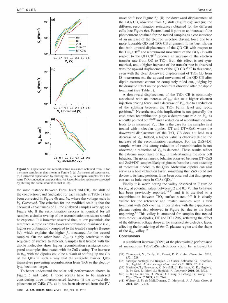
the same distance between Fermi level and CB), the shift ofthe conduction band (indicated for each sample in Table 1) hasbeen corrected in Figure 6b and 6c, where the voltage scale isVF Corrected. The criterion for the modified scale is that thechemical capacitances of all the analyzed samples overlap; seeFigure 6b. If the recombination process is identical for allsamples, a similar overlap of the recombination resistance shouldbe expected. It is however observed that, at low potentials, thereference sample exhibits lower recombination resistance (i.e.,higher recombination) compared to the treated samples (Figure6c), which explains the higher jsc measured for the treatedsamples. On the other hand, Rrec is highly sensitive to thesequence of surface treatments. Samples first treated with thedipole molecules show higher recombination resistance com-pared to samples first treated with the ZnS coating. The increasein Rrec with the dipoles could be a result of shifting up the CBof the QDs in such a way that the energetic barrier, QDsthemselves preventing recombination from TiO2 to the electro-lyte, becomes larger.
To better understand the solar cell performances shown inFigure 5 and Table 1, these results have to be analyzedconsidering three interconnected factors: (i) the upward dis-placement of CdSe CB, as it has been observed from the PV
onset shift (see Figure 2); (ii) the downward displacement ofthe TiO2 CB, observed from Cµ shift (Figure 6a); and (iii) thedifferent recombination resistances obtained for the differentcells (see Figure 6c). Factors i and ii point to an increase of thephotocurrent obtained for the treated samples as a consequenceof an increase of the electron injection driving force due to amore favorable QD and TiO2 CB alignment. It has been shownthat both upward displacement of the QD CB with respect tothe TiO2 CB29 and a downward movement of the TiO2 CB withrespect to the QD CB37 produce an increase of the electrontransfer rate from QD to TiO2. But, this effect is not sym-metrical, and a higher increase of the transfer rate is observedwith the upward displacement of the QD CB.29,37 In this sense,even with the clear downward displacement of TiO2 CB fromIS measurements, the upward movement of the QD CB afterdipole treatment cannot be completely ruled out, judging bythe dramatic effect on the photocurrent observed after the dipoletreatment (see Table 1).
A downward displacement of the TiO2 CB is commonlyassociated with an increase of jsc, due to a higher electroninjection driving force, and a decrease of Voc, due to a reductionof the splitting between the TiO2 Fermi level and redoxposition.38 Nevertheless, this implication is not generally thecase since recombination plays a determinant role on Voc asrecently pointed out,39,40 and a reduction of recombination alsoleads to an increased Voc. This is the case for the samples firsttreated with molecular dipoles, DT and DT+ZnS, where thedownward displacement of the TiO2 CB does not lead to adecrease of Voc. Indeed, a higher value is observed due to theincrease of the recombination resistance. For the ZnS+DTsample, where this strong reduction of recombination is notobserved, a reduction of Voc is detected. These results reflectthe extreme importance of Rrec in understanding the solar cellbehavior. The nonsymmetric behavior observed between DT+ZnSand ZnS+DT samples likely originates from the direct attachingof molecular dipoles to the QDs. Molecular dipoles can alsoserve as a hole extraction layer, something that ZnS could notdo due to its band position. It has been observed that thiol groupscan act as hole traps in CdSe QDs.41
Finally it is worth noting the valley observed in Figure 6cfor Rrec at potential values between 0.2 and 0.3 V. This behaviorhas been previously reported,33,35 and it is ascribed to arecombination between TiO2 surface states.13,33 It is clearlyvisible for the reference and treated samples with a firsttreatment with ZnS coating. It correlates with the capacitanceplateau region also observed in Figure 6c, due to the bandunpinning.13 This valley is smoothed for samples first treatedwith molecular dipoles, DT and DT+ZnS, reflecting the effectof the different voltage drops at the intermediate dielectric layer,affecting the broadening of the Cµ plateau region and the shapeof the Rrec valley.13
Conclusions
A significant increase (600%) of the photovoltaic performanceof mesoporous TiO2/CdSe electrodes could be achieved by
(37) Chakrapani, V.; Tvrdy, K.; Kamat, P. V. J. Am. Chem. Soc. 2010,132, 1228.
(38) Fabregat-Santiago, F.; Bisquert, J.; Garcia-Belmonte, G.; Boschloo,G.; Hagfeldt, A. Sol. Energy Mater. Sol. Cells 2005, 87, 117.
(39) Marinado, T.; Nonomura, K.; Nissfolk, J.; Karlsson, M. K.; Hagberg,D. P.; Sun, L.; Mori, S.; Hagfeldt, A. Langmuir 2010, 26, 2592.
(40) Li, R.; Lv, X.; Shi, D.; Zhou, D.; Cheng, Y.; Zhang, G.; Wang, P. J.Phys. Chem. C 2009, 113, 7469.
(41) Wuister, S. F.; de MelloDonega, C.; Meijerink, A. J. Phys. Chem. B2004, 108, 17393.
Figure 6. Capacitance and recombination resistance obtained from IS forthe same samples as that shown in Figure 5. (a) As-measured capacitance.(b) Corrected capacitance by shifting the VF to compare samples with thesame TiO2 conduction band position. (c) Recombination resistance correctedby shifting the same amount as that in (b).
6838 J. AM. CHEM. SOC. 9 VOL. 132, NO. 19, 2010
A R T I C L E S Barea et al.

tailoring both charge injection and recombination dynamics byproper surface modification of the nanostructure. The synergisticinteraction of the adequate combination of both surface treat-ments tested in the present study (grafting of molecular dipolesand ZnS coating) is reflected in the increased IPCE and thephotovoltaic properties obtained: 9.74 mA/cm2 and 1.60%efficiency. In addition, the key role of the surface treatments inrecombination control has been stressed to understand the solarcell performance. Finally, it can be concluded that surfacetreatments allow designing both injection and recombinationdynamics for QDSCs. This fact could have important implica-tions for the development of this kind of cells.
Acknowledgment. This work was partially supported by theMinisterio de Ciencia e Innovacion of Spain under the projects
HOPE CSD2007-00007, JES-NANOSOLAR PLE2009-0042, andMAT2007-62982 and by Generalitat Valenciana under theproject ACOMP/2009/095 and PROMETEO/2009/058. Theauthors acknowledge also the support of the Israeli ScienceFoundation, Bikura Program. E.M.B. would also like to ac-knowledge the financial support from the European ScienceFoundation (ESF) through the activity entitled “New Generationof Organic based Photovoltaic Devices”. S.G. acknowledges theMinisterio de Ciencia e Innovacion for its support through theRamon y Cajal program. Dr. Beatriz Julian Lopez is gratefullyacknowledged for her support with the diffuse reflectivitymeasurements.
JA101752D
J. AM. CHEM. SOC. 9 VOL. 132, NO. 19, 2010 6839
Quantum Dot Sensitized Solar Cells A R T I C L E S