Embed Size (px)
Citation preview
Design of Improved Distribution Panel
for the DC House
By
Nolan Joksch
Senior Project
ELECTRICAL ENGINEERING DEPARTMENT
California Polytechnic State University
San Luis Obispo
June 2013

ii
Table of Contents
Section Page
Title Page ……..………………………………………………………………………………….. i
Table of Contents ………………………………………………………………………………… ii
List of Tables and/or Figures …………………………………………………………………….. iii
Acknowledgements ………………………………………………………………………………. iv
Abstract …………………………………………………………………………………………… v
I. Introduction/Background ………………………………………………………………………. 1
II. Requirements ………………………………………………………………………………….. 6
III. Design ………………………………………………………………………………………… 9
IV. Test Plans …………………………………………………………………………………….. 14
V. Development and Construction ………………………………………………………………... 16
VI. Integration and Test Results ………………………………………………………………….. 20
VII. Conclusion …………………………………………………………………………………... 23
VIII. Bibliography ………………………………………………………………………………... 25
Appendices
A. Specifications …………………………………………………………………………………. 26
B. Parts List and Costs …………………………………………………………………………… 27
C. Schedule - Time Estimates ……………………………………………………………………. 28
D. Analysis of Senior Project Design…………………………………………………………… 30
E. Plexiglas Cover Dimensions…………………………………………………………………. 34
iii
Tables/Figures
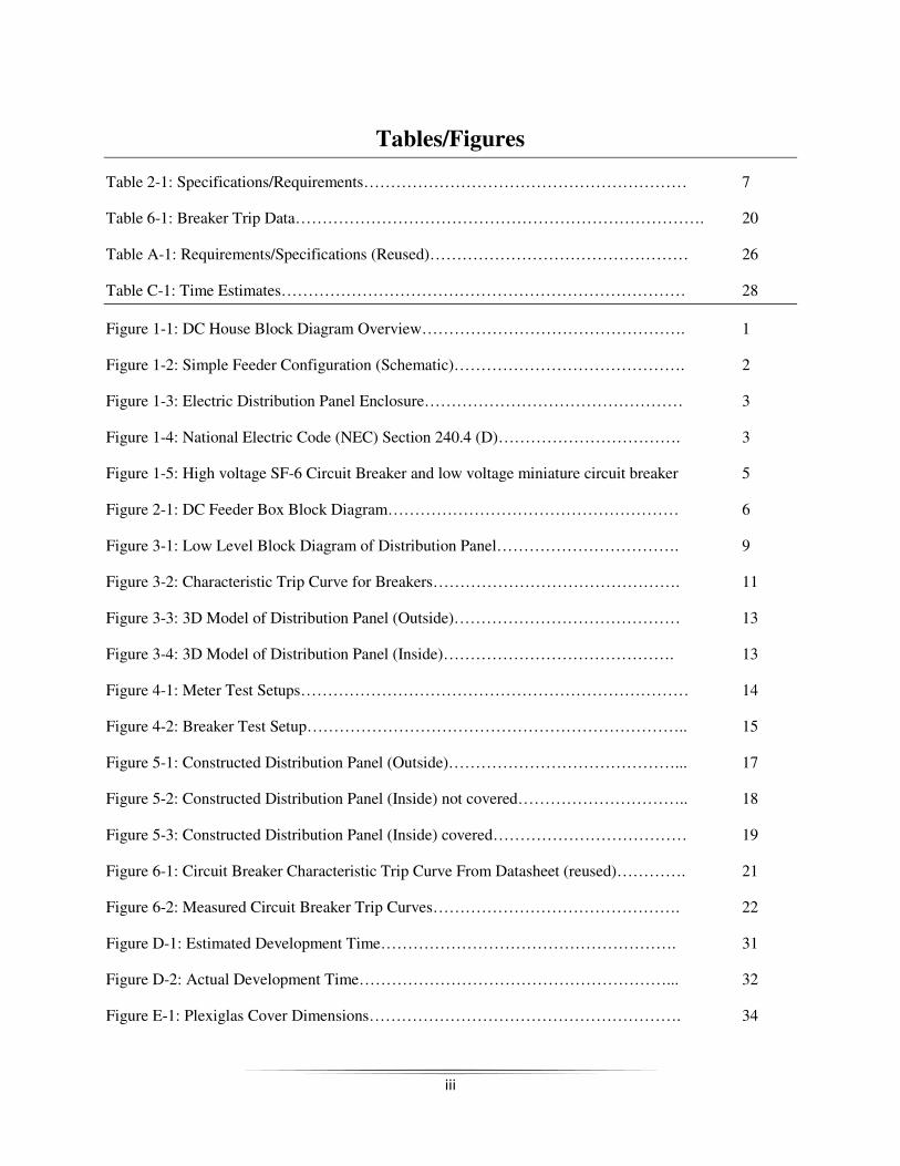
Table 2-1: Specifications/Requirements…………………………………………………… 7
Table 6-1: Breaker Trip Data…………………………………………………………………. 20
Table A-1: Requirements/Specifications (Reused)………………………………………… 26
Table C-1: Time Estimates………………………………………………………………… 28
Figure 1-1: DC House Block Diagram Overview…………………………………………. 1
Figure 1-2: Simple Feeder Configuration (Schematic)……………………………………. 2
Figure 1-3: Electric Distribution Panel Enclosure………………………………………… 3
Figure 1-4: National Electric Code (NEC) Section 240.4 (D)……………………………. 3
Figure 1-5: High voltage SF-6 Circuit Breaker and low voltage miniature circuit breaker 5
Figure 2-1: DC Feeder Box Block Diagram……………………………………………… 6
Figure 3-1: Low Level Block Diagram of Distribution Panel……………………………. 9
Figure 3-2: Characteristic Trip Curve for Breakers………………………………………. 11
Figure 3-3: 3D Model of Distribution Panel (Outside)…………………………………… 13
Figure 3-4: 3D Model of Distribution Panel (Inside)……………………………………. 13
Figure 4-1: Meter Test Setups……………………………………………………………… 14
Figure 4-2: Breaker Test Setup…………………………………………………………….. 15
Figure 5-1: Constructed Distribution Panel (Outside)……………………………………... 17
Figure 5-2: Constructed Distribution Panel (Inside) not covered………………………….. 18
Figure 5-3: Constructed Distribution Panel (Inside) covered……………………………… 19
Figure 6-1: Circuit Breaker Characteristic Trip Curve From Datasheet (reused)…………. 21
Figure 6-2: Measured Circuit Breaker Trip Curves………………………………………. 22
Figure D-1: Estimated Development Time………………………………………………. 31
Figure D-2: Actual Development Time…………………………………………………... 32
Figure E-1: Plexiglas Cover Dimensions…………………………………………………. 34
iv
Acknowledgements
There are so many people I’d like to thank that have supported and encouraged me in
accomplishing my goal of graduating, but those I think deserve it most are my parents and Professor
Taufik. Thank you, Mom and Dad, for always believing I could do this, and making it possible to do so.
Thank you, Taufik, for being an exemplary educator who cares deeply about his students and their
education. For this project specifically, I’d like to thank Jaime Carmo for helping so much with the
construction of my project.

v
Abstract
The DC House is a humanitarian project intended to provide electricity to rural areas that would
benefit from electricity, but are too remote to have access to it. This particular project is to design and
construct the feeder box for the electrical distribution system to distribute power to the system as well as
protect it. Building an electrical panel that is easily maintained and, above all, safe for the user is key to
this project.
I. Introduction
DC House Overview
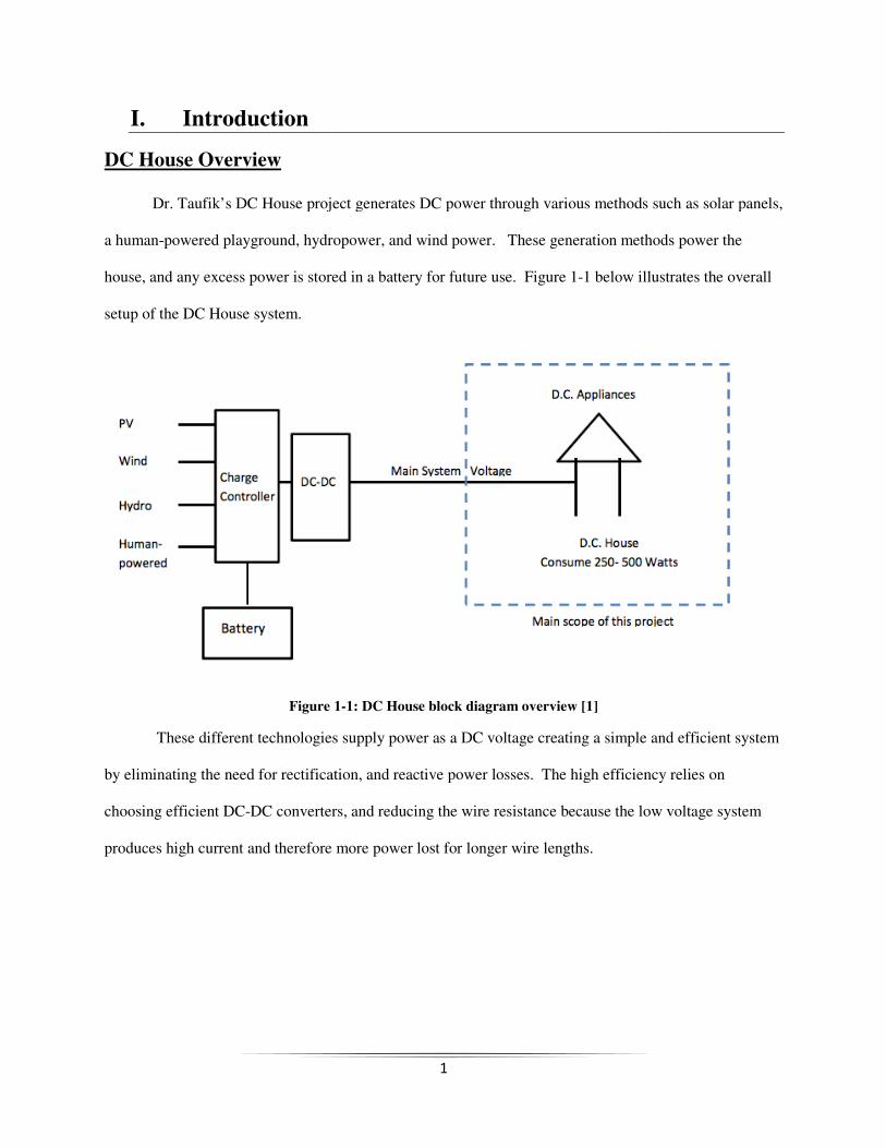
Dr. Taufik’s DC House project generates DC power through various methods such as solar panels,
a human-powered playground, hydropower, and wind power. These generation methods power the
house, and any excess power is stored in a battery for future use.
setup of the DC House system.
Figure
These different technologies supply power as a DC voltage creating a simple and efficient system
by eliminating the need for rectification, and reactive power losses. The high efficiency relies on
choosing efficient DC-DC converters, and reducing the wire resistance because the low voltage system
produces high current and therefore more power lost for longer wire lengths.
1
DC House project generates DC power through various methods such as solar panels,
powered playground, hydropower, and wind power. These generation methods power the
house, and any excess power is stored in a battery for future use. Figure 1-1 below illustrates the overall
Figure 1-1: DC House block diagram overview [1]
These different technologies supply power as a DC voltage creating a simple and efficient system
for rectification, and reactive power losses. The high efficiency relies on
DC converters, and reducing the wire resistance because the low voltage system
produces high current and therefore more power lost for longer wire lengths.
DC House project generates DC power through various methods such as solar panels,
powered playground, hydropower, and wind power. These generation methods power the
elow illustrates the overall
These different technologies supply power as a DC voltage creating a simple and efficient system
for rectification, and reactive power losses. The high efficiency relies on
DC converters, and reducing the wire resistance because the low voltage system
DC Feeder Box
Figure 1-
Description:
A Feeder Box is a device composed of switches, fuses, and sometimes reclosers
distribution systems to limit the impact of faults on customers
shows one of the many configurations an electrical feeder can be put in. This distribution panel will be
configured in an even simpler setup.
reclosers, this succinct description sums up the reasons for feeder boxes. Feeder boxes are not needed for
the circuit to operate, but are used mainly because things go wrong. Faults occur
them to a minimum amount of customers. Feeders are designed to fail so that the faults are easy to fix,
easy to find, and protects components further along in the circuit that would be damaged from high
currents.
With Respect to the DC House:
The main problems solved by constructing a feeder box in the DC House are power distribution,
circuit isolation, and user safety. As determined by Jessica Chaidez’s senior project findings, the most
efficient in terms of power bus voltage for this
2
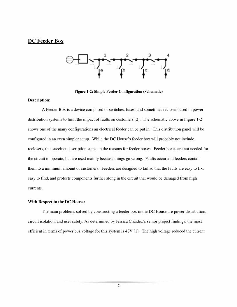
-2: Simple Feeder Configuration (Schematic)
A Feeder Box is a device composed of switches, fuses, and sometimes reclosers
distribution systems to limit the impact of faults on customers [2]. The schematic above in Figure 1
shows one of the many configurations an electrical feeder can be put in. This distribution panel will be
etup. While the DC House’s feeder box will probably not include
reclosers, this succinct description sums up the reasons for feeder boxes. Feeder boxes are not needed for
the circuit to operate, but are used mainly because things go wrong. Faults occur and feeders contain
them to a minimum amount of customers. Feeders are designed to fail so that the faults are easy to fix,
easy to find, and protects components further along in the circuit that would be damaged from high
The main problems solved by constructing a feeder box in the DC House are power distribution,
circuit isolation, and user safety. As determined by Jessica Chaidez’s senior project findings, the most
efficient in terms of power bus voltage for this system is 48V [1]. The high voltage reduced the current
A Feeder Box is a device composed of switches, fuses, and sometimes reclosers used in power
The schematic above in Figure 1-2
shows one of the many configurations an electrical feeder can be put in. This distribution panel will be
While the DC House’s feeder box will probably not include
reclosers, this succinct description sums up the reasons for feeder boxes. Feeder boxes are not needed for
and feeders contain
them to a minimum amount of customers. Feeders are designed to fail so that the faults are easy to fix,
easy to find, and protects components further along in the circuit that would be damaged from high
The main problems solved by constructing a feeder box in the DC House are power distribution,
circuit isolation, and user safety. As determined by Jessica Chaidez’s senior project findings, the most
. The high voltage reduced the current
for this fixed 600W system thereby reducing the power losses.
Figure 1
In typical households there are several loads present
In order to provide adequate current and voltage levels to the applications the loads are put on separate
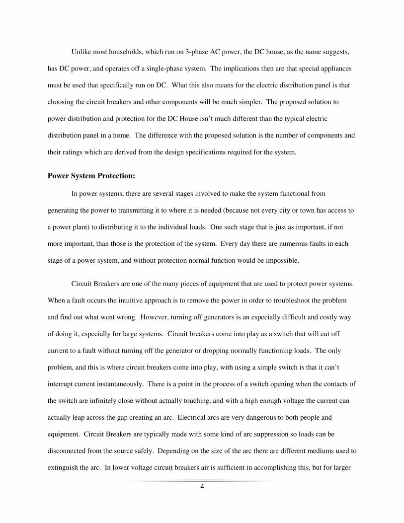
branches. The feeder box will feed three branches that will not exceed 15A since they will be wired
14 AWG wires as required by NEC 240.4(D) [3]
Figure 1-4: National Electric
3
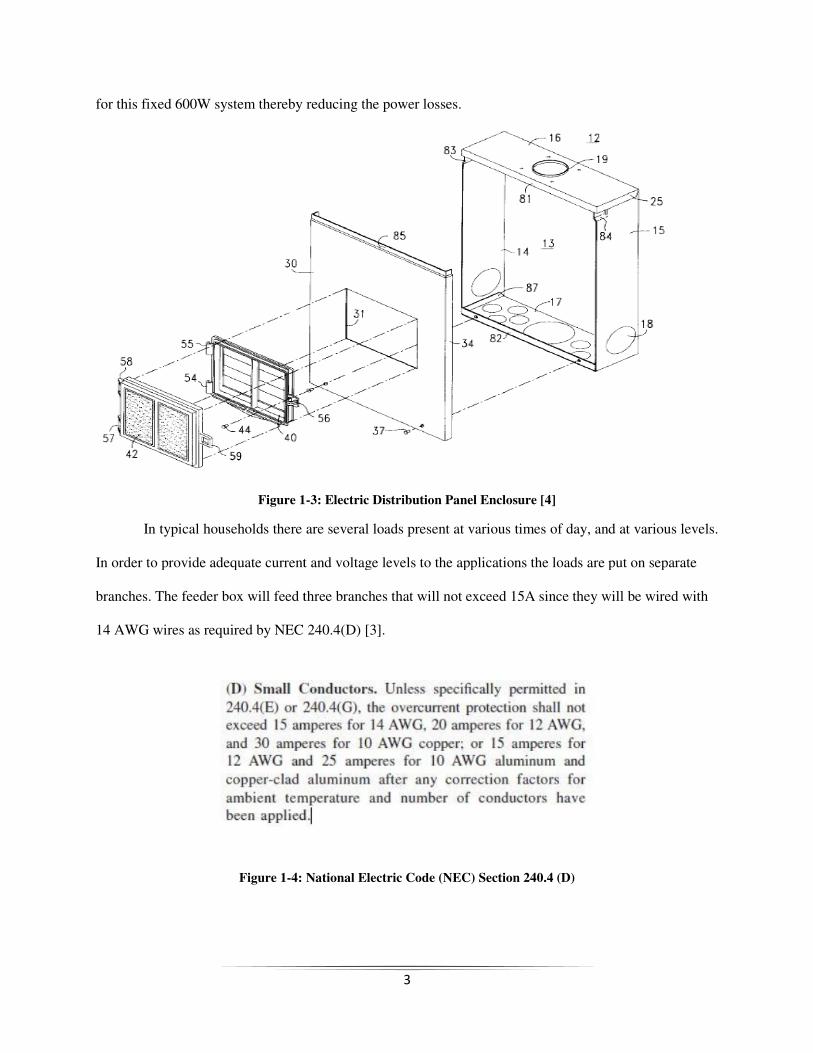
hereby reducing the power losses.
1-3: Electric Distribution Panel Enclosure [4]
In typical households there are several loads present at various times of day, and at various levels.
In order to provide adequate current and voltage levels to the applications the loads are put on separate
branches. The feeder box will feed three branches that will not exceed 15A since they will be wired
s as required by NEC 240.4(D) [3].
: National Electric Code (NEC) Section 240.4 (D)
at various times of day, and at various levels.
In order to provide adequate current and voltage levels to the applications the loads are put on separate
branches. The feeder box will feed three branches that will not exceed 15A since they will be wired with
4
Unlike most households, which run on 3-phase AC power, the DC house, as the name suggests,
has DC power, and operates off a single-phase system. The implications then are that special appliances
must be used that specifically run on DC. What this also means for the electric distribution panel is that
choosing the circuit breakers and other components will be much simpler. The proposed solution to
power distribution and protection for the DC House isn’t much different than the typical electric
distribution panel in a home. The difference with the proposed solution is the number of components and
their ratings which are derived from the design specifications required for the system.
Power System Protection:
In power systems, there are several stages involved to make the system functional from
generating the power to transmitting it to where it is needed (because not every city or town has access to
a power plant) to distributing it to the individual loads. One such stage that is just as important, if not
more important, than those is the protection of the system. Every day there are numerous faults in each
stage of a power system, and without protection normal function would be impossible.
Circuit Breakers are one of the many pieces of equipment that are used to protect power systems.
When a fault occurs the intuitive approach is to remove the power in order to troubleshoot the problem
and find out what went wrong. However, turning off generators is an especially difficult and costly way
of doing it, especially for large systems. Circuit breakers come into play as a switch that will cut off
current to a fault without turning off the generator or dropping normally functioning loads. The only
problem, and this is where circuit breakers come into play, with using a simple switch is that it can’t
interrupt current instantaneously. There is a point in the process of a switch opening when the contacts of
the switch are infinitely close without actually touching, and with a high enough voltage the current can
actually leap across the gap creating an arc. Electrical arcs are very dangerous to both people and
equipment. Circuit Breakers are typically made with some kind of arc suppression so loads can be
disconnected from the source safely. Depending on the size of the arc there are different mediums used to
extinguish the arc. In lower voltage circuit breakers air is sufficient in accomplishing this, but for larger
5
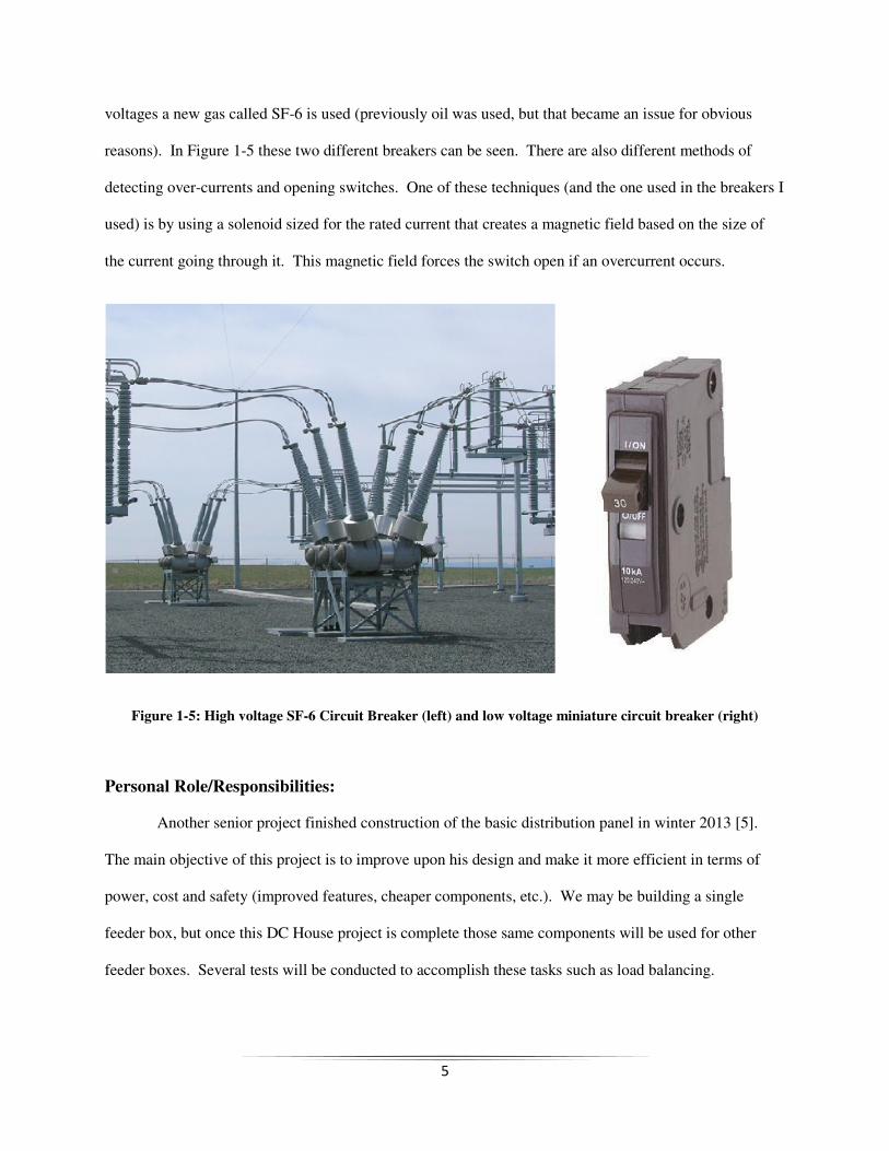
voltages a new gas called SF-6 is used (previously oil was used, but that became an issue for obvious
reasons). In Figure 1-5 these two different breakers can be seen. There are also different methods of
detecting over-currents and opening switches. One of these techniques (and the one used in the breakers I
used) is by using a solenoid sized for the rated current that creates a magnetic field based on the size of
the current going through it. This magnetic field forces the switch open if an overcurrent occurs.
Figure 1-5: High voltage SF-6 Circuit Breaker (left) and low voltage miniature circuit breaker (right)
Personal Role/Responsibilities:
Another senior project finished construction of the basic distribution panel in winter 2013 [5].
The main objective of this project is to improve upon his design and make it more efficient in terms of
power, cost and safety (improved features, cheaper components, etc.). We may be building a single
feeder box, but once this DC House project is complete those same components will be used for other
feeder boxes. Several tests will be conducted to accomplish these tasks such as load balancing.
II. Requirements/Specifications
The main requirements for this project given by Professor Taufik
panel that would distribute power to a number of load
below in Figure 2-1 shows where the distribution panel will fit into the house’s power system. Several
numerical specifications were given fr
600W and a main bus voltage of 48V [1][5]. It was determined
would be the voltage used because it was the most efficient voltag
efficient load configuration was found to be to split the loads into three branches.
System Block Diagram:
Knowledge of the users of this DC House led to the requirements t
constructed with safety and reliability in mind so that the users would not ever have the need to perform
any sort of maintenance or part replacement on it.
specifications of this project.
6
Requirements/Specifications
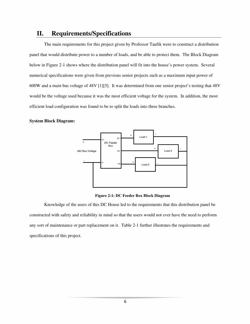
The main requirements for this project given by Professor Taufik were to construct a distribution
panel that would distribute power to a number of loads, and be able to protect them. The Block Diagram
1 shows where the distribution panel will fit into the house’s power system. Several
ifications were given from previous senior projects such as a maximum input power of
600W and a main bus voltage of 48V [1][5]. It was determined from one senior project’s testing
would be the voltage used because it was the most efficient voltage for the system. In addi
efficient load configuration was found to be to split the loads into three branches.
Figure 2-1: DC Feeder Box Block Diagram
Knowledge of the users of this DC House led to the requirements that this distribution panel be
constructed with safety and reliability in mind so that the users would not ever have the need to perform
any sort of maintenance or part replacement on it. Table 2-1 further illustrates the requirements and
were to construct a distribution
s, and be able to protect them. The Block Diagram
1 shows where the distribution panel will fit into the house’s power system. Several
om previous senior projects such as a maximum input power of
from one senior project’s testing that 48V
In addition, the most
hat this distribution panel be
constructed with safety and reliability in mind so that the users would not ever have the need to perform
1 further illustrates the requirements and
7
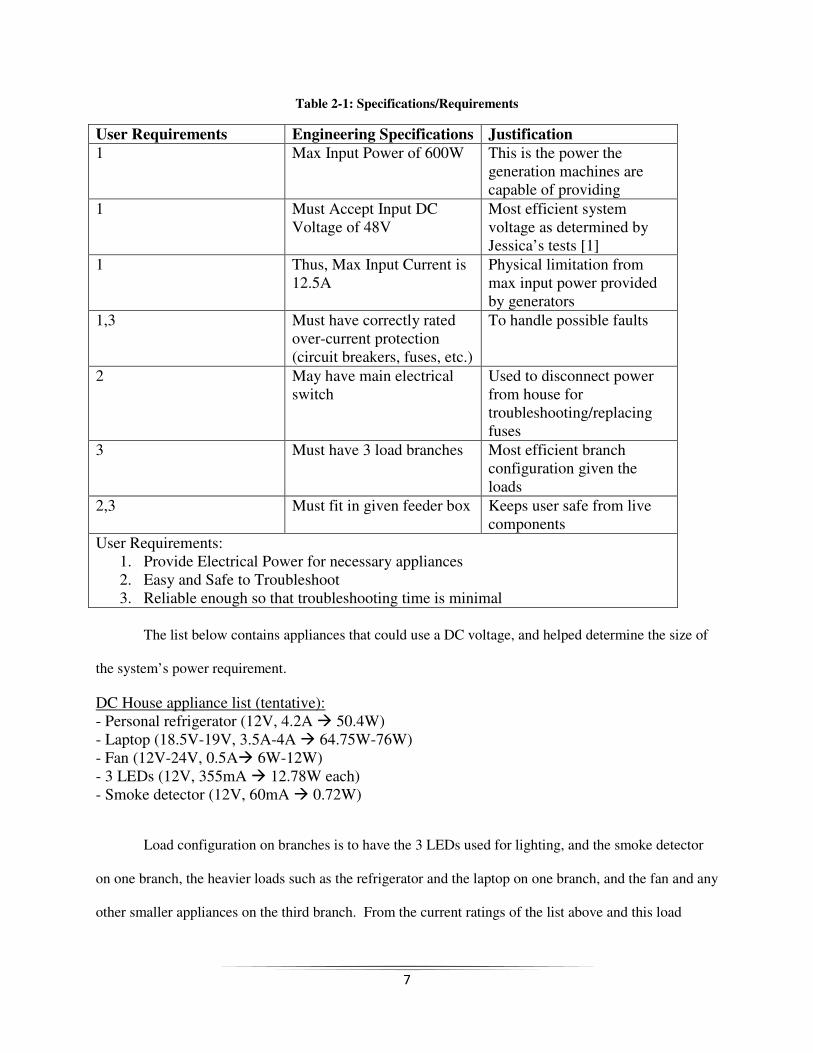
Table 2-1: Specifications/Requirements
User Requirements Engineering Specifications Justification
1 Max Input Power of 600W This is the power the generation machines are capable of providing
1 Must Accept Input DC Voltage of 48V
Most efficient system voltage as determined by Jessica’s tests [1]
1 Thus, Max Input Current is 12.5A
Physical limitation from max input power provided by generators
1,3 Must have correctly rated over-current protection (circuit breakers, fuses, etc.)
To handle possible faults
2 May have main electrical switch
Used to disconnect power from house for troubleshooting/replacing fuses
3 Must have 3 load branches Most efficient branch configuration given the loads
2,3 Must fit in given feeder box Keeps user safe from live components
User Requirements: 1. Provide Electrical Power for necessary appliances 2. Easy and Safe to Troubleshoot 3. Reliable enough so that troubleshooting time is minimal
The list below contains appliances that could use a DC voltage, and helped determine the size of
the system’s power requirement.
DC House appliance list (tentative): - Personal refrigerator (12V, 4.2A � 50.4W) - Laptop (18.5V-19V, 3.5A-4A � 64.75W-76W) - Fan (12V-24V, 0.5A� 6W-12W) - 3 LEDs (12V, 355mA � 12.78W each) - Smoke detector (12V, 60mA � 0.72W)
Load configuration on branches is to have the 3 LEDs used for lighting, and the smoke detector
on one branch, the heavier loads such as the refrigerator and the laptop on one branch, and the fan and any
other smaller appliances on the third branch. From the current ratings of the list above and this load

8
configuration it was calculated that one load (assumed to have all loads running) would have 0.5A on it,
one with 1.125A, and one with about 7A on it. With this information the ratings of the circuit breakers
was determined to be two 2A breakers and one 7.5A breaker. Setting the circuit breakers to these ratings
prevents anymore current beyond the rating of the equipment to be drawn in the case of a fault.
9
III. Design
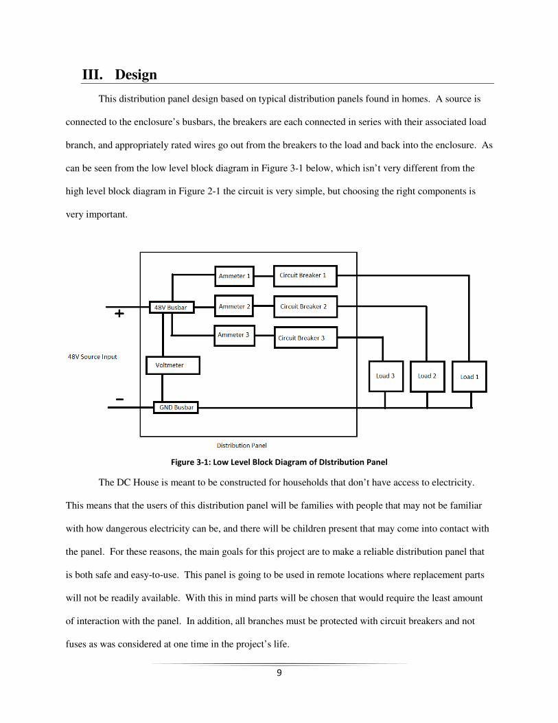
This distribution panel design based on typical distribution panels found in homes. A source is
connected to the enclosure’s busbars, the breakers are each connected in series with their associated load
branch, and appropriately rated wires go out from the breakers to the load and back into the enclosure. As
can be seen from the low level block diagram in Figure 3-1 below, which isn’t very different from the
high level block diagram in Figure 2-1 the circuit is very simple, but choosing the right components is
very important.
Figure 3-1: Low Level Block Diagram of DIstribution Panel
The DC House is meant to be constructed for households that don’t have access to electricity.
This means that the users of this distribution panel will be families with people that may not be familiar
with how dangerous electricity can be, and there will be children present that may come into contact with
the panel. For these reasons, the main goals for this project are to make a reliable distribution panel that
is both safe and easy-to-use. This panel is going to be used in remote locations where replacement parts
will not be readily available. With this in mind parts will be chosen that would require the least amount
of interaction with the panel. In addition, all branches must be protected with circuit breakers and not
fuses as was considered at one time in the project’s life.
10
Fuses vs. Circuit Breakers: Which one is best?
Fuses are a very useful overcurrent protection device that blows—eliminating the electrical
path—when a current above the fuse’s rating is detected. They are small, inexpensive (less than a dollar
per fuse), and trip very quickly. However, they are a one-shot device, and must be replaced once blown.
In contrast, circuit breakers can trip and be reset with just the flip of a switch. The downside of circuit
breakers for this project is that they are very expensive in comparison; they were about $40 per breaker.
Still, circuit breakers are a better choice not just because they don’t need to be replaced, but they are safer
as well. If fuses were used instead of breakers it would be dangerous to replace the fuses because the
source side of the branch would still be alive.
Circuit Breakers:
The circuit breakers are the core of the distribution panel, providing overcurrent protection for the
rest of the power distribution system in the house. There are a few ratings that must be paid attention to
when choosing breakers for a system. As the specifications require a 48V DC voltage as a source for the
loads the breakers must be rated to handle a maximum DC voltage of at least 48V. The current rating of a
circuit breaker is the maximum amount of current that the breaker can handle without tripping. The
specifications state that the maximum input power to the panel would be 600W. With the bus voltage at
48V this means that the maximum total current that can be running through the panel would be 12.5A. In
a previous project, it was determined that three branches would be the optimal amount with the larger
loads on one branch and two lighter loaded branches so that the danger is minimalized to one branch
rather than two. The two smaller branches are rated at 2A and the larger branch at 7.5A.
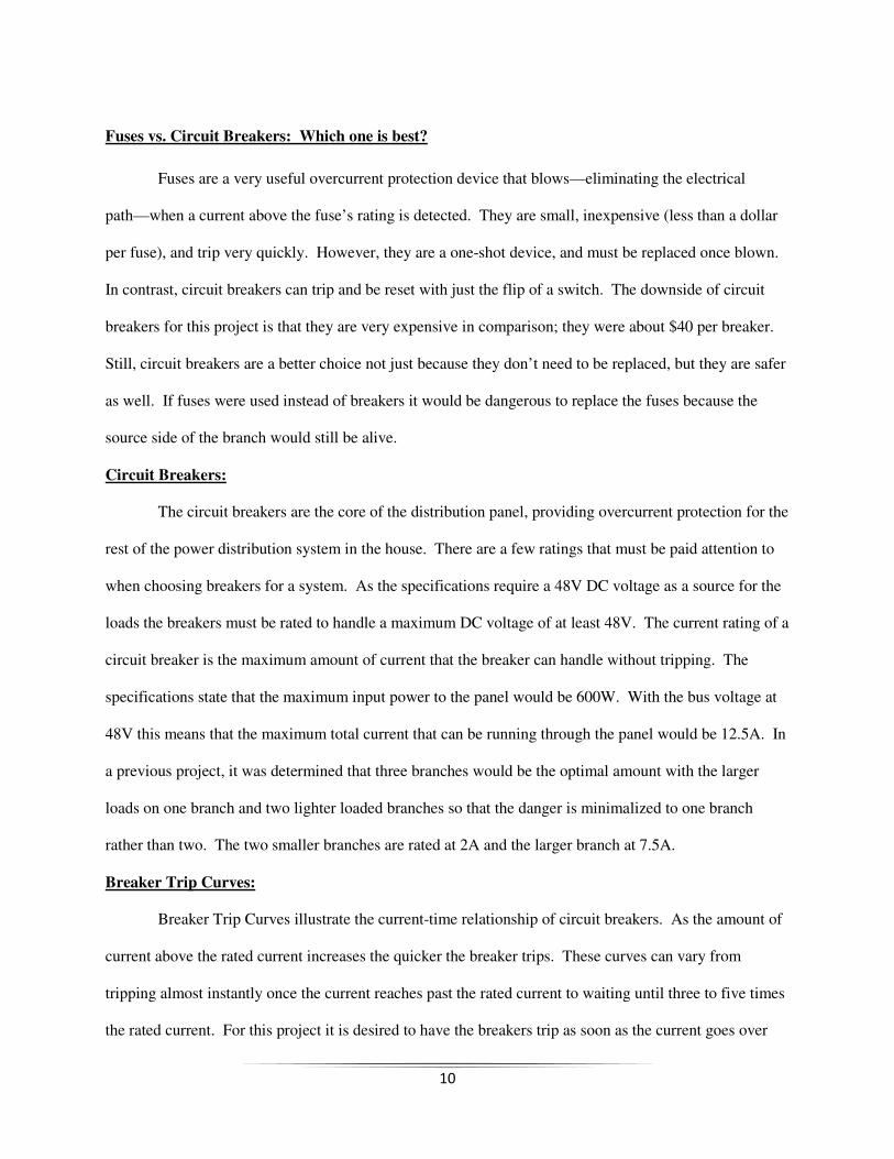
Breaker Trip Curves:
Breaker Trip Curves illustrate the current-time relationship of circuit breakers. As the amount of
current above the rated current increases the quicker the breaker trips. These curves can vary from
tripping almost instantly once the current reaches past the rated current to waiting until three to five times
the rated current. For this project it is desired to have the breakers trip as soon as the current goes over
11
the rating. The reason for this is that the maximum current that will be drawn by any fault will be 12.5A,
and while this will certainly trip for the 2A breaker it isn’t sure to trip the 7.5A breaker. Even a small
amount of overcurrent, say, 9A for the 7.5A breaker may not trip for some trip curves. If 9A remains
running through the branch it may damage the loads, and this is something we want to avoid. The
characteristic trip curve shown below in Figure 3-2 is taken from the datasheet of the breakers being used
for the design. According to this curve, the breakers should trip at 125% of the rated current, but may not
trip below this point.
Figure 3-2: Characteristic Trip Curve for Breakers [6]
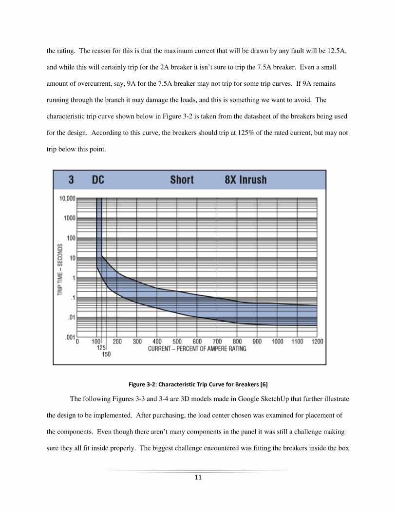
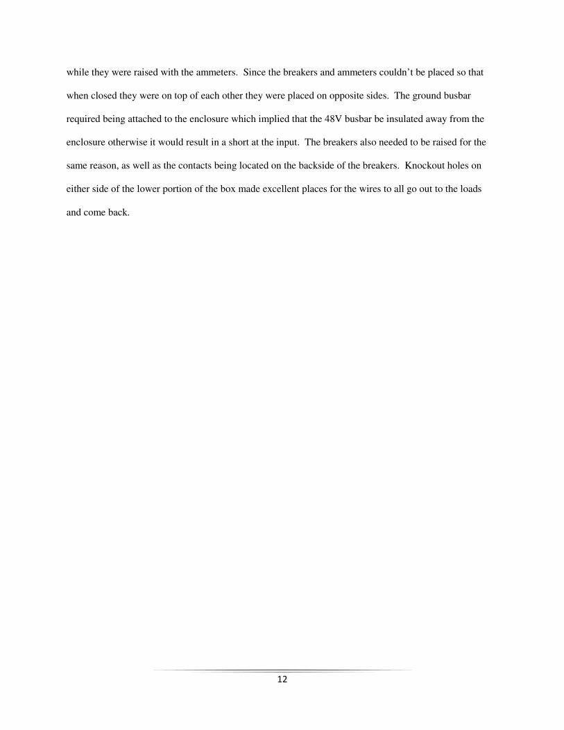
The following Figures 3-3 and 3-4 are 3D models made in Google SketchUp that further illustrate
the design to be implemented. After purchasing, the load center chosen was examined for placement of
the components. Even though there aren’t many components in the panel it was still a challenge making
sure they all fit inside properly. The biggest challenge encountered was fitting the breakers inside the box
12
while they were raised with the ammeters. Since the breakers and ammeters couldn’t be placed so that
when closed they were on top of each other they were placed on opposite sides. The ground busbar
required being attached to the enclosure which implied that the 48V busbar be insulated away from the
enclosure otherwise it would result in a short at the input. The breakers also needed to be raised for the
same reason, as well as the contacts being located on the backside of the breakers. Knockout holes on
either side of the lower portion of the box made excellent places for the wires to all go out to the loads
and come back.
13
Figure 6: 3D Model of Distribution Panel (Outside)
Figure 7: 3D Model of Distribution Panel (Inside)
14
IV. Test Plans
Tests are to be conducted on each individually to ensure that they will operate within the
parameters of the specifications given. Then after construction the components will be tested again for
verification. For the meters this means that they display the correct values of current and voltage at the
point they are measuring. For the circuit breakers this means that they will follow the characteristic trip
curve given by the manufacturer, and trip when they should.
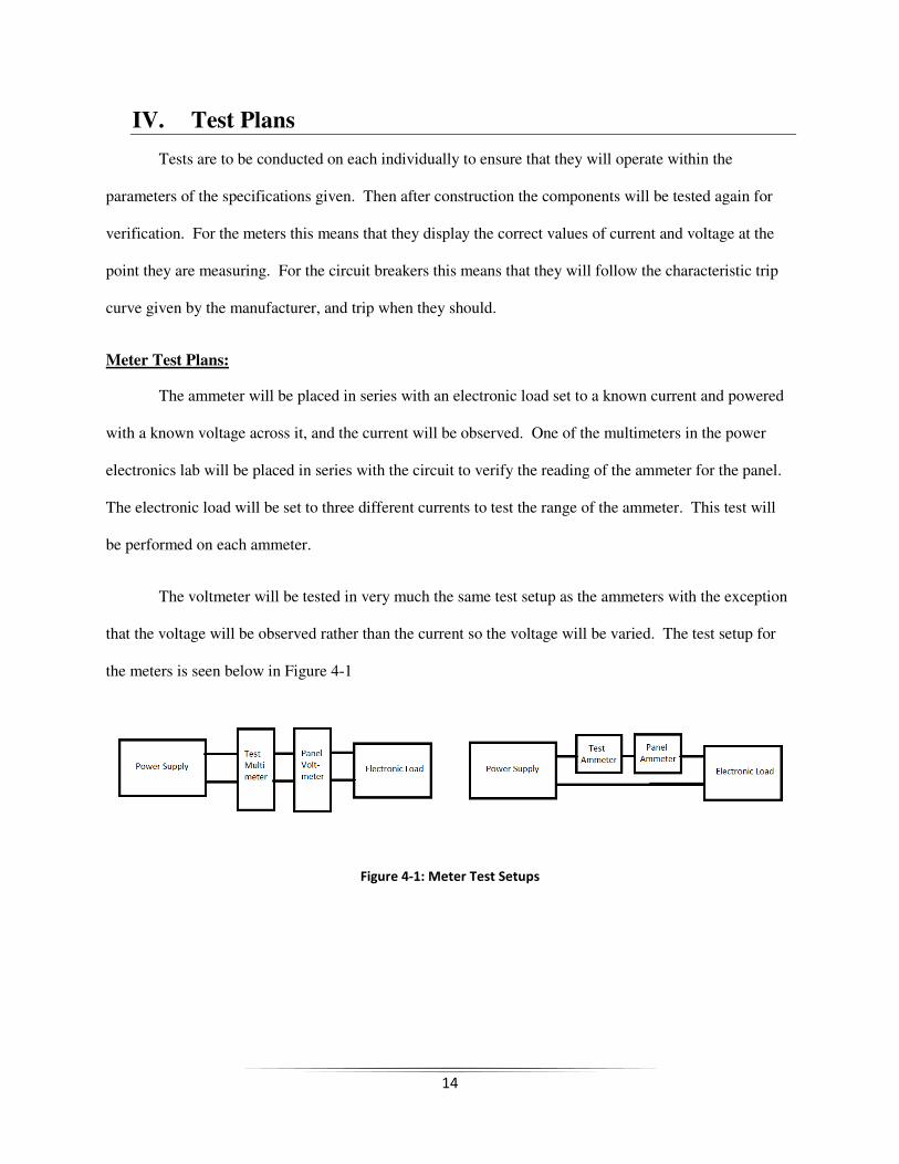
Meter Test Plans:
The ammeter will be placed in series with an electronic load set to a known current and powered
with a known voltage across it, and the current will be observed. One of the multimeters in the power
electronics lab will be placed in series with the circuit to verify the reading of the ammeter for the panel.
The electronic load will be set to three different currents to test the range of the ammeter. This test will
be performed on each ammeter.
The voltmeter will be tested in very much the same test setup as the ammeters with the exception
that the voltage will be observed rather than the current so the voltage will be varied. The test setup for
the meters is seen below in Figure 4-1
Figure 4-1: Meter Test Setups
15
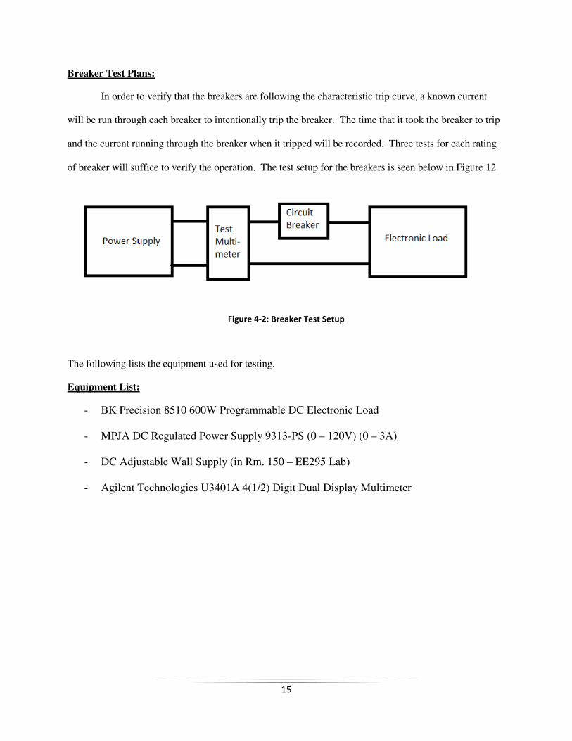
Breaker Test Plans:
In order to verify that the breakers are following the characteristic trip curve, a known current
will be run through each breaker to intentionally trip the breaker. The time that it took the breaker to trip
and the current running through the breaker when it tripped will be recorded. Three tests for each rating
of breaker will suffice to verify the operation. The test setup for the breakers is seen below in Figure 12
Figure 4-2: Breaker Test Setup
The following lists the equipment used for testing.
Equipment List:
- BK Precision 8510 600W Programmable DC Electronic Load
- MPJA DC Regulated Power Supply 9313-PS (0 – 120V) (0 – 3A)
- DC Adjustable Wall Supply (in Rm. 150 – EE295 Lab)
- Agilent Technologies U3401A 4(1/2) Digit Dual Display Multimeter
16
V. Development and Construction
The majority of the construction involved improvements made to the enclosure of the distribution
panel rather than the actual circuit. To make these improvements the workshop located in the
Engineering East building was extremely helpful, and Mr. Jaime Carmo made this possible.
Before adjustments or construction could begin the parts needed to be purchased and gathered. A
parts list (with complete information) and cost analysis is located in Appendix B. The information there
details the decisions and thought-process involved in choosing those parts.
The Load Center
(Outside)
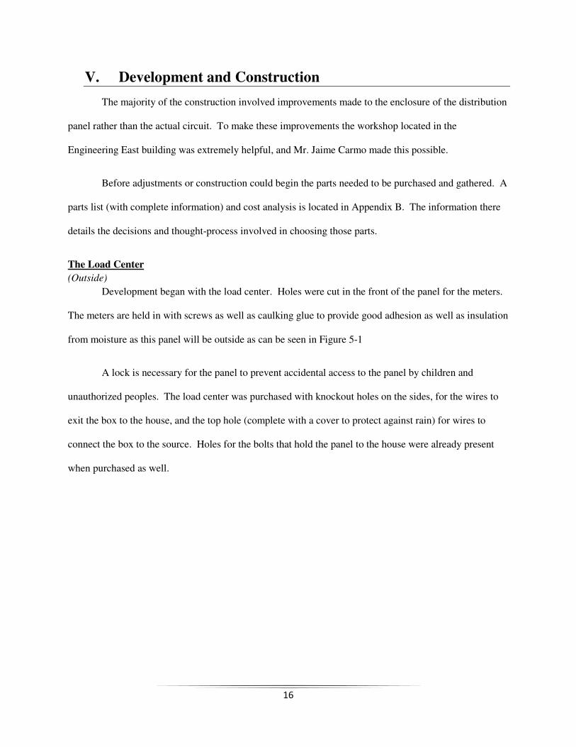
Development began with the load center. Holes were cut in the front of the panel for the meters.
The meters are held in with screws as well as caulking glue to provide good adhesion as well as insulation
from moisture as this panel will be outside as can be seen in Figure 5-1
A lock is necessary for the panel to prevent accidental access to the panel by children and
unauthorized peoples. The load center was purchased with knockout holes on the sides, for the wires to
exit the box to the house, and the top hole (complete with a cover to protect against rain) for wires to
connect the box to the source. Holes for the bolts that hold the panel to the house were already present
when purchased as well.
17
Figure 5-1: Constructed Distribution Panel (Outside)
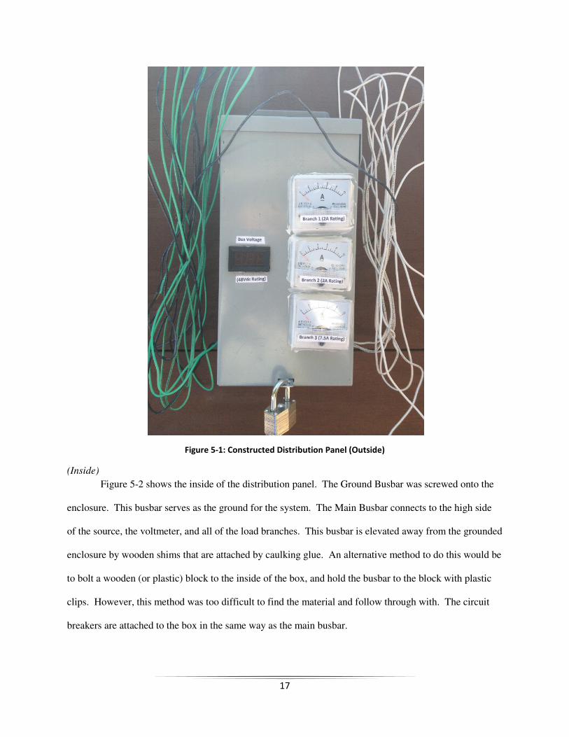
(Inside)
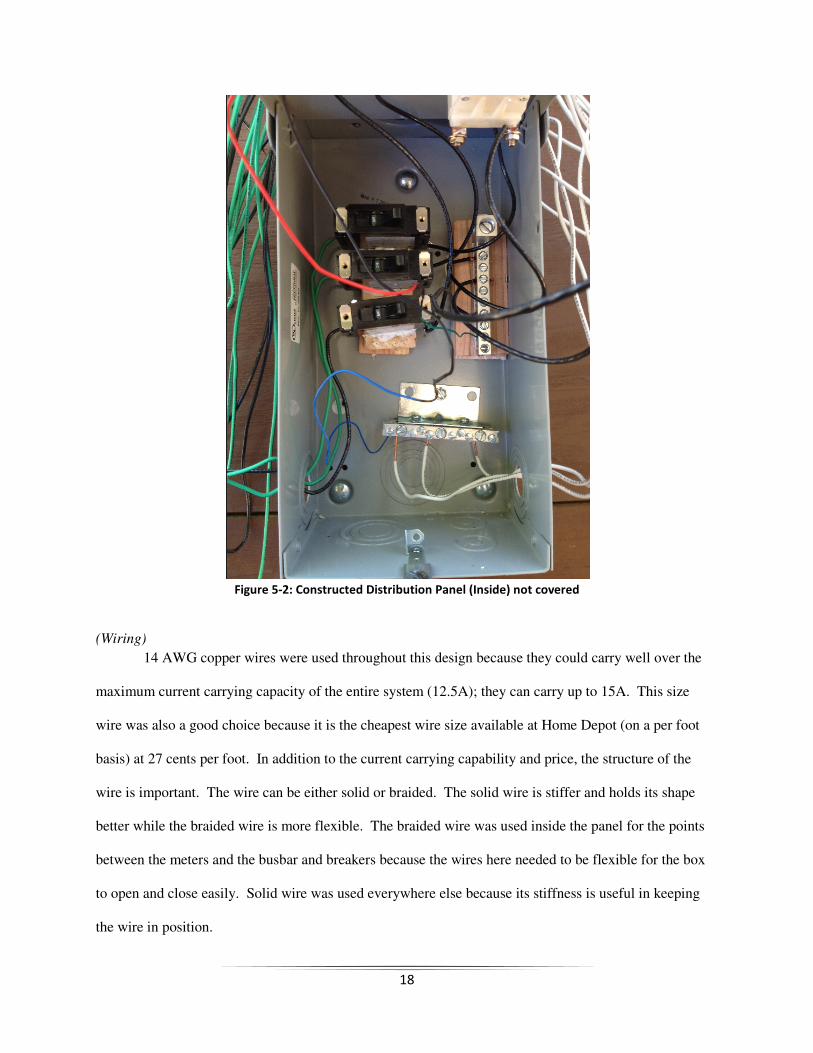
Figure 5-2 shows the inside of the distribution panel. The Ground Busbar was screwed onto the
enclosure. This busbar serves as the ground for the system. The Main Busbar connects to the high side
of the source, the voltmeter, and all of the load branches. This busbar is elevated away from the grounded
enclosure by wooden shims that are attached by caulking glue. An alternative method to do this would be
to bolt a wooden (or plastic) block to the inside of the box, and hold the busbar to the block with plastic
clips. However, this method was too difficult to find the material and follow through with. The circuit
breakers are attached to the box in the same way as the main busbar.
18
Figure 5-2: Constructed Distribution Panel (Inside) not covered
(Wiring)
14 AWG copper wires were used throughout this design because they could carry well over the
maximum current carrying capacity of the entire system (12.5A); they can carry up to 15A. This size
wire was also a good choice because it is the cheapest wire size available at Home Depot (on a per foot
basis) at 27 cents per foot. In addition to the current carrying capability and price, the structure of the
wire is important. The wire can be either solid or braided. The solid wire is stiffer and holds its shape
better while the braided wire is more flexible. The braided wire was used inside the panel for the points
between the meters and the busbar and breakers because the wires here needed to be flexible for the box
to open and close easily. Solid wire was used everywhere else because its stiffness is useful in keeping
the wire in position.
19
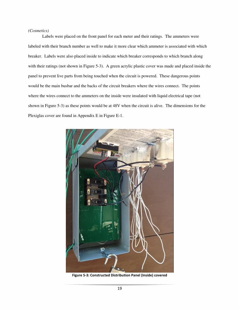
(Cosmetics)
Labels were placed on the front panel for each meter and their ratings. The ammeters were
labeled with their branch number as well to make it more clear which ammeter is associated with which
breaker. Labels were also placed inside to indicate which breaker corresponds to which branch along
with their ratings (not shown in Figure 5-3). A green acrylic plastic cover was made and placed inside the
panel to prevent live parts from being touched when the circuit is powered. These dangerous points
would be the main busbar and the backs of the circuit breakers where the wires connect. The points
where the wires connect to the ammeters on the inside were insulated with liquid electrical tape (not
shown in Figure 5-3) as these points would be at 48V when the circuit is alive. The dimensions for the
Plexiglas cover are found in Appendix E in Figure E-1.
Figure 5-3: Constructed Distribution Panel (Inside) covered

20
21
VI. Integration and Test Results
Meter Test Results:
The voltmeter correctly measured and displayed the voltage of the main bus within a few tenths
of a volt. The voltmeter read 48.4VDC when the power source was supplying 48.6VDC. It’s important
to note that the maximum voltage rating of the voltmeter is 50VDC, and should not be used to measure
voltages higher than this. The ammeters were more difficult to test as they were analog meters, but as
long as the meters were upright it was obvious that the meter read the correct current. Like with the
Voltmeter, it is important to note that the ammeters are rated for up to 10A, so in normal operation they
will display the correct values, but not if a fault current goes above 10A.
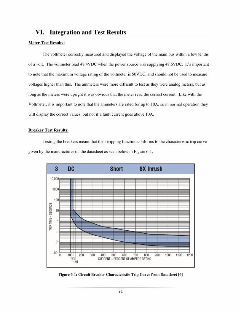
Breaker Test Results:
Testing the breakers meant that their tripping function conforms to the characteristic trip curve
given by the manufacturer on the datasheet as seen below in Figure 6-1.
Figure 6-1: Circuit Breaker Characteristic Trip Curve from Datasheet [6]
22
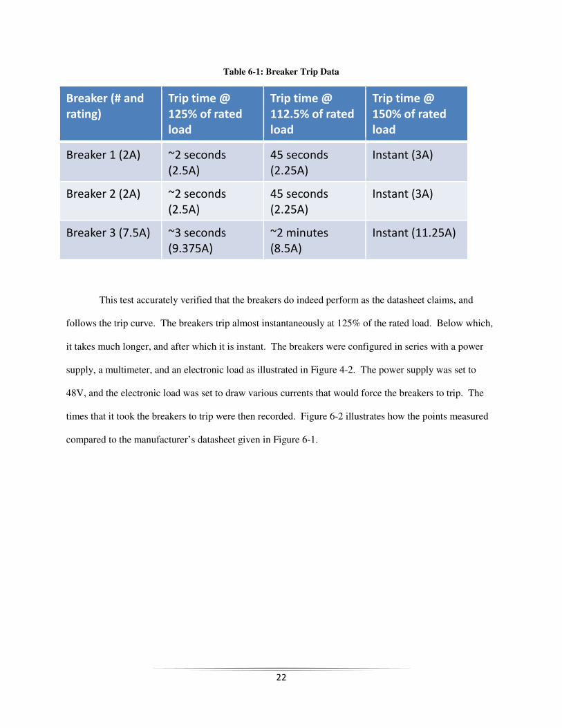
Table 6-1: Breaker Trip Data
Breaker (# and
rating) Trip time @
125% of rated
load
Trip time @
112.5% of rated
load
Trip time @
150% of rated
load
Breaker 1 (2A) ~2 seconds
(2.5A) 45 seconds
(2.25A) Instant (3A)
Breaker 2 (2A) ~2 seconds
(2.5A) 45 seconds
(2.25A) Instant (3A)
Breaker 3 (7.5A) ~3 seconds
(9.375A) ~2 minutes
(8.5A) Instant (11.25A)
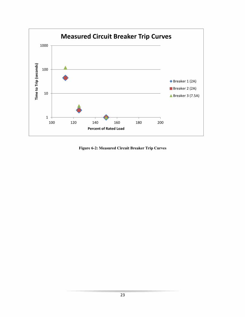
This test accurately verified that the breakers do indeed perform as the datasheet claims, and
follows the trip curve. The breakers trip almost instantaneously at 125% of the rated load. Below which,
it takes much longer, and after which it is instant. The breakers were configured in series with a power
supply, a multimeter, and an electronic load as illustrated in Figure 4-2. The power supply was set to
48V, and the electronic load was set to draw various currents that would force the breakers to trip. The
times that it took the breakers to trip were then recorded. Figure 6-2 illustrates how the points measured
compared to the manufacturer’s datasheet given in Figure 6-1.
23
Figure 6-2: Measured Circuit Breaker Trip Curves
1
10
100
1000
100 120 140 160 180 200
Tim
e t
o T
rip
(se
con
ds)
Percent of Rated Load
Measured Circuit Breaker Trip Curves
Breaker 1 (2A)
Breaker 2 (2A)
Breaker 3 (7.5A)
24
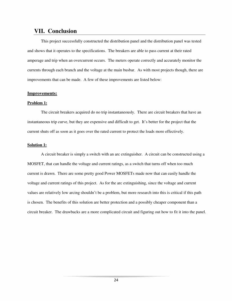
VII. Conclusion
This project successfully constructed the distribution panel and the distribution panel was tested
and shows that it operates to the specifications. The breakers are able to pass current at their rated
amperage and trip when an overcurrent occurs. The meters operate correctly and accurately monitor the
currents through each branch and the voltage at the main busbar. As with most projects though, there are
improvements that can be made. A few of these improvements are listed below:
Improvements:
Problem 1:
The circuit breakers acquired do no trip instantaneously. There are circuit breakers that have an
instantaneous trip curve, but they are expensive and difficult to get. It’s better for the project that the
current shuts off as soon as it goes over the rated current to protect the loads more effectively.
Solution 1:
A circuit breaker is simply a switch with an arc extinguisher. A circuit can be constructed using a
MOSFET, that can handle the voltage and current ratings, as a switch that turns off when too much
current is drawn. There are some pretty good Power MOSFETs made now that can easily handle the
voltage and current ratings of this project. As for the arc extinguishing, since the voltage and current
values are relatively low arcing shouldn’t be a problem, but more research into this is critical if this path
is chosen. The benefits of this solution are better protection and a possibly cheaper component than a
circuit breaker. The drawbacks are a more complicated circuit and figuring out how to fit it into the panel.
25
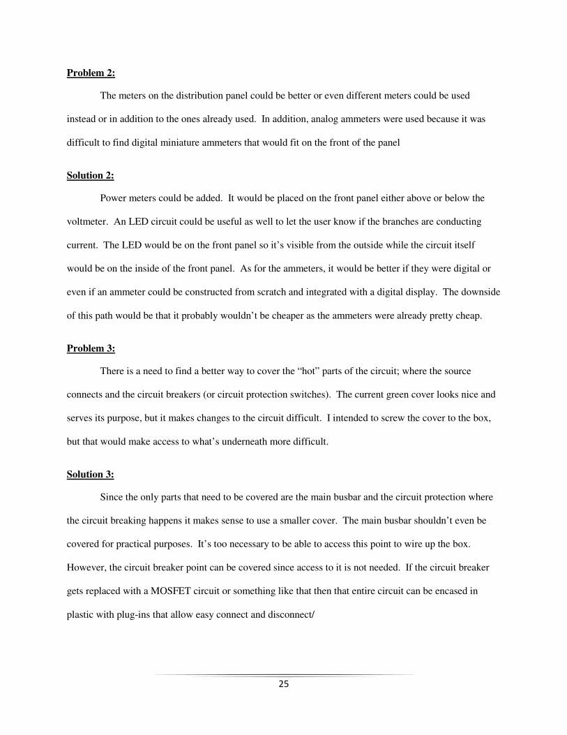
Problem 2:
The meters on the distribution panel could be better or even different meters could be used
instead or in addition to the ones already used. In addition, analog ammeters were used because it was
difficult to find digital miniature ammeters that would fit on the front of the panel
Solution 2:
Power meters could be added. It would be placed on the front panel either above or below the
voltmeter. An LED circuit could be useful as well to let the user know if the branches are conducting
current. The LED would be on the front panel so it’s visible from the outside while the circuit itself
would be on the inside of the front panel. As for the ammeters, it would be better if they were digital or
even if an ammeter could be constructed from scratch and integrated with a digital display. The downside
of this path would be that it probably wouldn’t be cheaper as the ammeters were already pretty cheap.
Problem 3:
There is a need to find a better way to cover the “hot” parts of the circuit; where the source
connects and the circuit breakers (or circuit protection switches). The current green cover looks nice and
serves its purpose, but it makes changes to the circuit difficult. I intended to screw the cover to the box,
but that would make access to what’s underneath more difficult.
Solution 3:
Since the only parts that need to be covered are the main busbar and the circuit protection where
the circuit breaking happens it makes sense to use a smaller cover. The main busbar shouldn’t even be
covered for practical purposes. It’s too necessary to be able to access this point to wire up the box.
However, the circuit breaker point can be covered since access to it is not needed. If the circuit breaker
gets replaced with a MOSFET circuit or something like that then that entire circuit can be encased in
plastic with plug-ins that allow easy connect and disconnect/
26
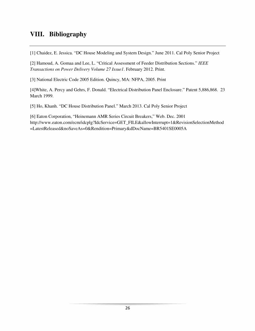
VIII. Bibliography
[1] Chaidez, E. Jessica. “DC House Modeling and System Design.” June 2011. Cal Poly Senior Project
[2] Hamoud, A. Gomaa and Lee, L. “Critical Assessment of Feeder Distribution Sections.” IEEE
Transactions on Power Delivery Volume 27 Issue1. February 2012. Print.
[3] National Electric Code 2005 Edition. Quincy, MA: NFPA, 2005. Print
[4]White, A. Percy and Gehrs, F. Donald. “Electrical Distribution Panel Enclosure.” Patent 5,886,868. 23
March 1999.
[5] Ho, Khanh. “DC House Distribution Panel.” March 2013. Cal Poly Senior Project
[6] Eaton Corporation, “Heinemann AMR Series Circuit Breakers,” Web. Dec. 2001
http://www.eaton.com/ecm/idcplg?IdcService=GET_FILE&allowInterrupt=1&RevisionSelectionMethod
=LatestReleased&noSaveAs=0&Rendition=Primary&dDocName=BR5401SE0005A
27
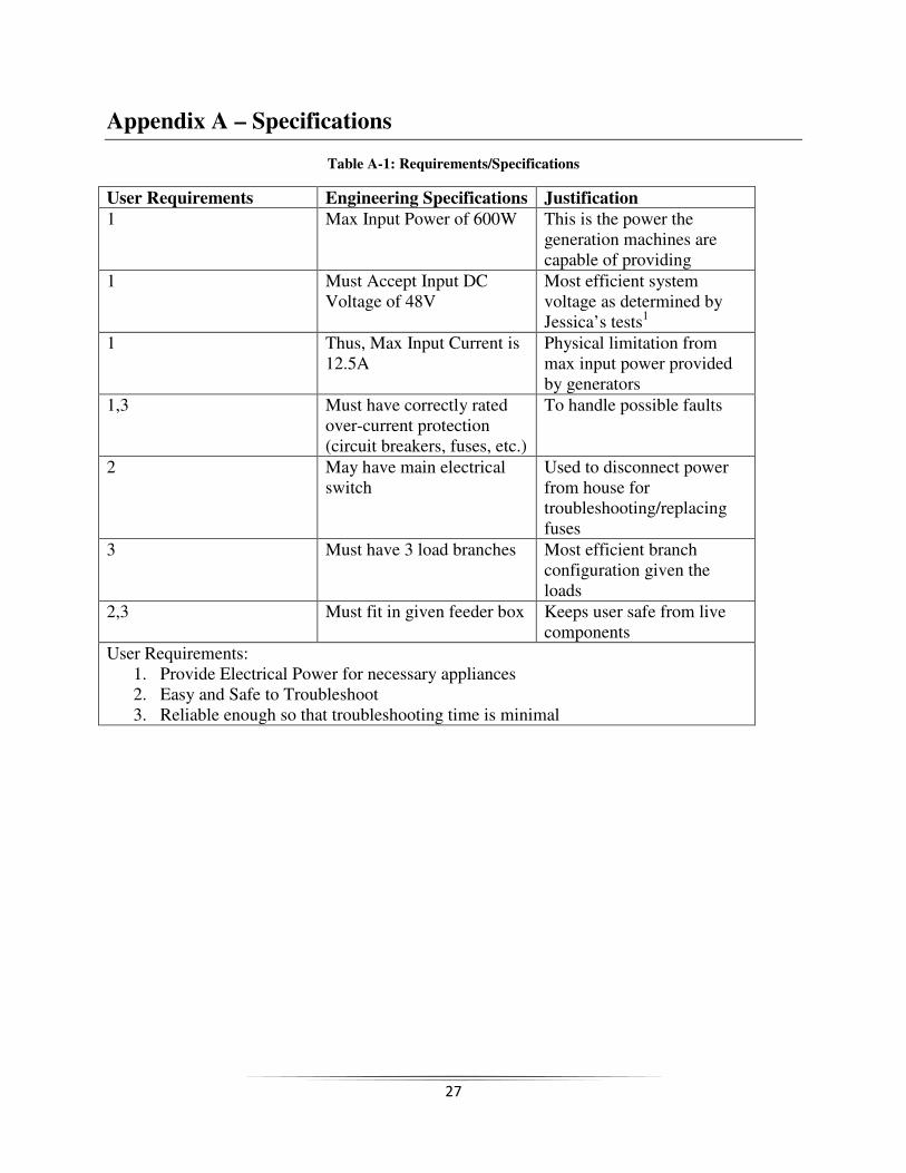
Appendix A – Specifications
Table A-1: Requirements/Specifications
User Requirements Engineering Specifications Justification
1 Max Input Power of 600W This is the power the generation machines are capable of providing
1 Must Accept Input DC Voltage of 48V
Most efficient system voltage as determined by Jessica’s tests1
1 Thus, Max Input Current is 12.5A
Physical limitation from max input power provided by generators
1,3 Must have correctly rated over-current protection (circuit breakers, fuses, etc.)
To handle possible faults
2 May have main electrical switch
Used to disconnect power from house for troubleshooting/replacing fuses
3 Must have 3 load branches Most efficient branch configuration given the loads
2,3 Must fit in given feeder box Keeps user safe from live components
User Requirements: 1. Provide Electrical Power for necessary appliances 2. Easy and Safe to Troubleshoot 3. Reliable enough so that troubleshooting time is minimal
28
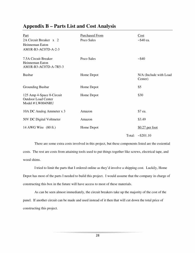
Appendix B – Parts List and Cost Analysis
Part Purchased From Cost
2A Circuit Breaker x 2 Poco Sales ~$40 ea.
Heinneman Eaton
AM1R-B3-AC07D-A-2-3
7.5A Circuit Breaker Poco Sales ~$40 Heinneman Eaton AM1R-B3-AC07D-A-7R5-3 Busbar Home Depot N/A (Include with Load Center) Grounding Busbar Home Depot $5 125 Amp 4-Space 8-Circuit Home Depot $30 Outdoor Load Center Model # LW004NRU 10A DC Analog Ammeter x 3 Amazon $7 ea. 50V DC Digital Voltmeter Amazon $3.49 14 AWG Wire (80 ft.) Home Depot $0.27 per foot Total: ~$201.10 There are some extra costs involved in this project, but these components listed are the essiential
costs. The rest are costs from attaining tools used to put things together like screws, electrical tape, and
wood shims.
I tried to limit the parts that I ordered online as they’d involve a shipping cost. Luckily, Home
Depot has most of the parts I needed to build this project. I would assume that the company in charge of
constructing this box in the future will have access to most of these materials.
As can be seen almost immediately, the circuit breakers take up the majority of the cost of the
panel. If another circuit can be made and used instead of it then that will cut down the total price of
constructing this project.
29
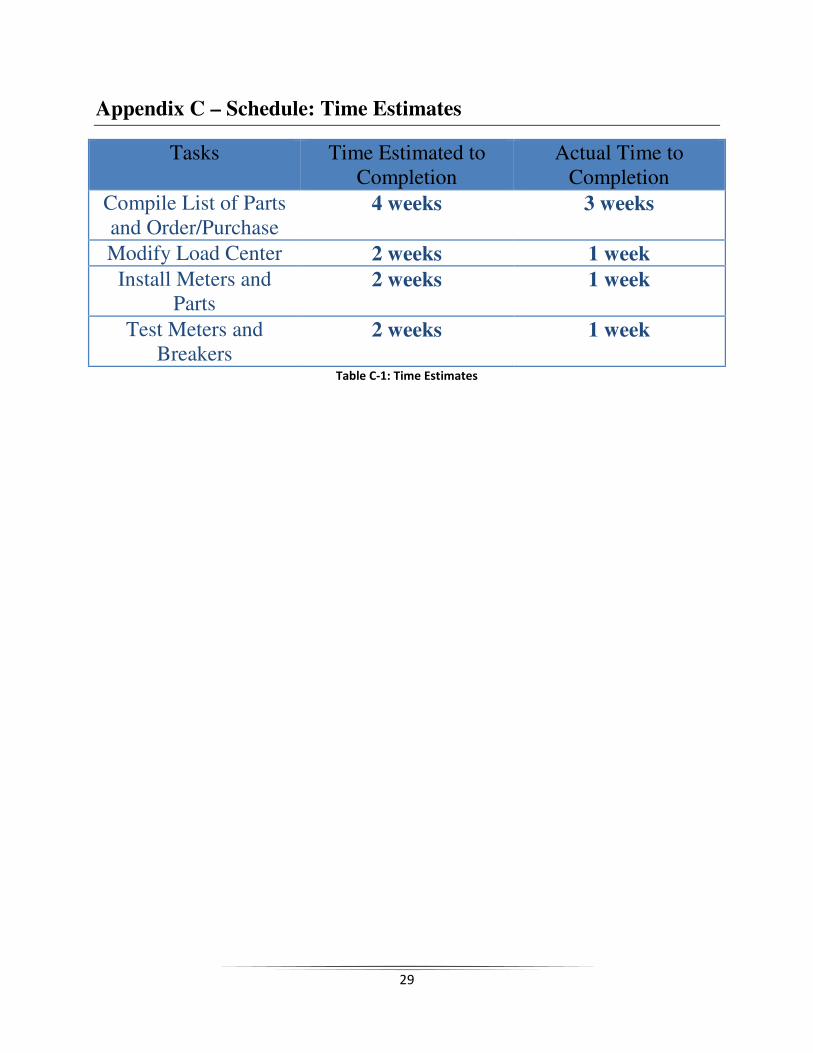
Appendix C – Schedule: Time Estimates
Tasks Time Estimated to Completion
Actual Time to Completion
Compile List of Parts and Order/Purchase
4 weeks 3 weeks
Modify Load Center 2 weeks 1 week
Install Meters and Parts
2 weeks 1 week
Test Meters and Breakers
2 weeks 1 week
Table C-1: Time Estimates
30
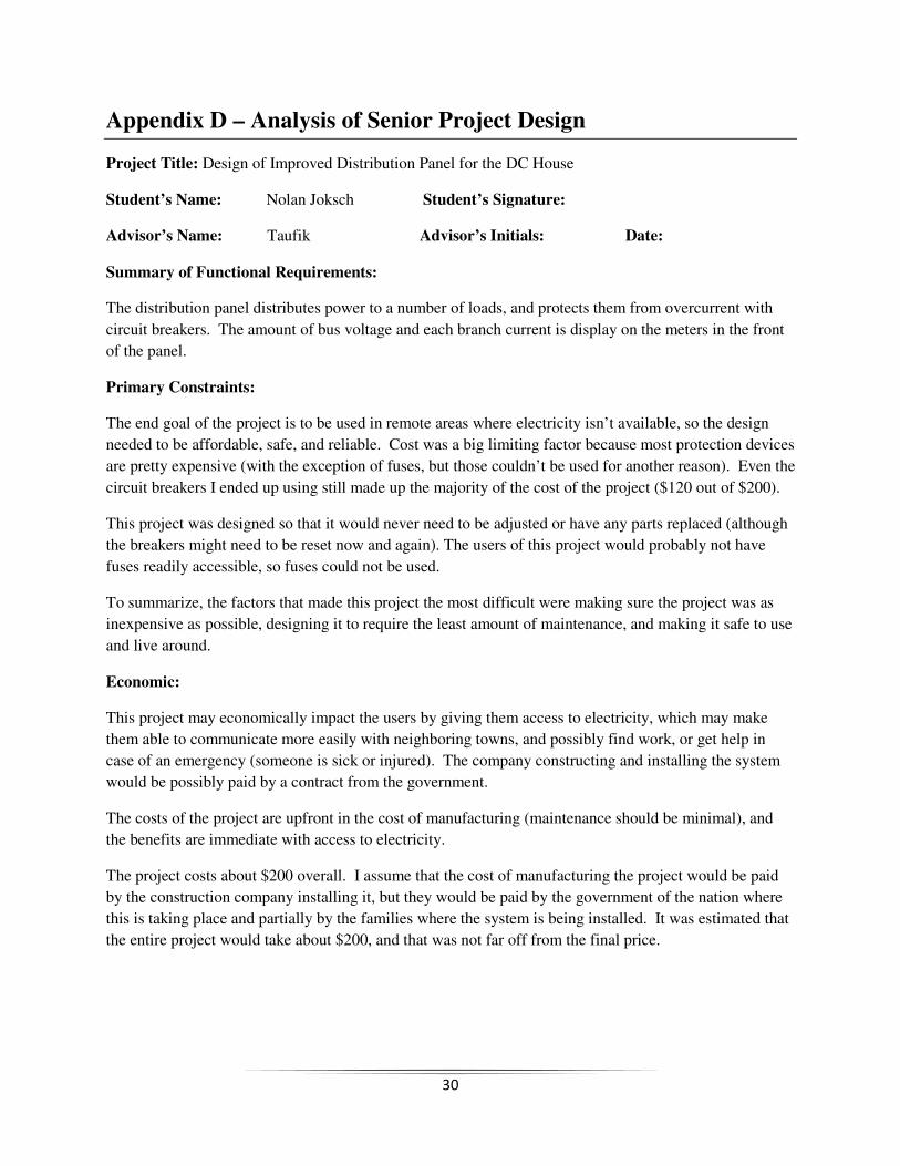
Appendix D – Analysis of Senior Project Design
Project Title: Design of Improved Distribution Panel for the DC House
Student’s Name: Nolan Joksch Student’s Signature:
Advisor’s Name: Taufik Advisor’s Initials: Date:
Summary of Functional Requirements:
The distribution panel distributes power to a number of loads, and protects them from overcurrent with
circuit breakers. The amount of bus voltage and each branch current is display on the meters in the front
of the panel.
Primary Constraints:
The end goal of the project is to be used in remote areas where electricity isn’t available, so the design
needed to be affordable, safe, and reliable. Cost was a big limiting factor because most protection devices
are pretty expensive (with the exception of fuses, but those couldn’t be used for another reason). Even the
circuit breakers I ended up using still made up the majority of the cost of the project ($120 out of $200).
This project was designed so that it would never need to be adjusted or have any parts replaced (although
the breakers might need to be reset now and again). The users of this project would probably not have
fuses readily accessible, so fuses could not be used.
To summarize, the factors that made this project the most difficult were making sure the project was as
inexpensive as possible, designing it to require the least amount of maintenance, and making it safe to use
and live around.
Economic:
This project may economically impact the users by giving them access to electricity, which may make
them able to communicate more easily with neighboring towns, and possibly find work, or get help in
case of an emergency (someone is sick or injured). The company constructing and installing the system
would be possibly paid by a contract from the government.
The costs of the project are upfront in the cost of manufacturing (maintenance should be minimal), and
the benefits are immediate with access to electricity.
The project costs about $200 overall. I assume that the cost of manufacturing the project would be paid
by the construction company installing it, but they would be paid by the government of the nation where
this is taking place and partially by the families where the system is being installed. It was estimated that
the entire project would take about $200, and that was not far off from the final price.
31
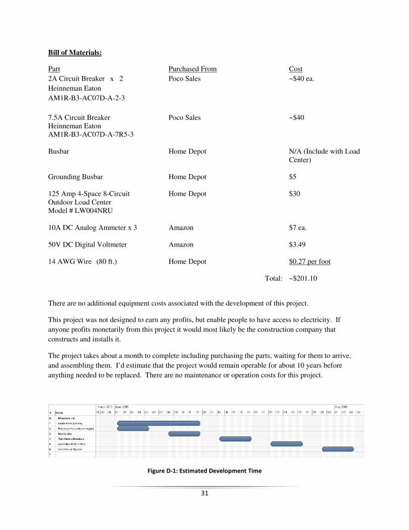
Bill of Materials:
Part Purchased From Cost
2A Circuit Breaker x 2 Poco Sales ~$40 ea.
Heinneman Eaton
AM1R-B3-AC07D-A-2-3
7.5A Circuit Breaker Poco Sales ~$40 Heinneman Eaton AM1R-B3-AC07D-A-7R5-3 Busbar Home Depot N/A (Include with Load Center) Grounding Busbar Home Depot $5 125 Amp 4-Space 8-Circuit Home Depot $30 Outdoor Load Center Model # LW004NRU 10A DC Analog Ammeter x 3 Amazon $7 ea. 50V DC Digital Voltmeter Amazon $3.49 14 AWG Wire (80 ft.) Home Depot $0.27 per foot Total: ~$201.10
There are no additional equipment costs associated with the development of this project.
This project was not designed to earn any profits, but enable people to have access to electricity. If
anyone profits monetarily from this project it would most likely be the construction company that
constructs and installs it.
The project takes about a month to complete including purchasing the parts, waiting for them to arrive,
and assembling them. I’d estimate that the project would remain operable for about 10 years before
anything needed to be replaced. There are no maintenance or operation costs for this project.
Figure D-1: Estimated Development Time
32
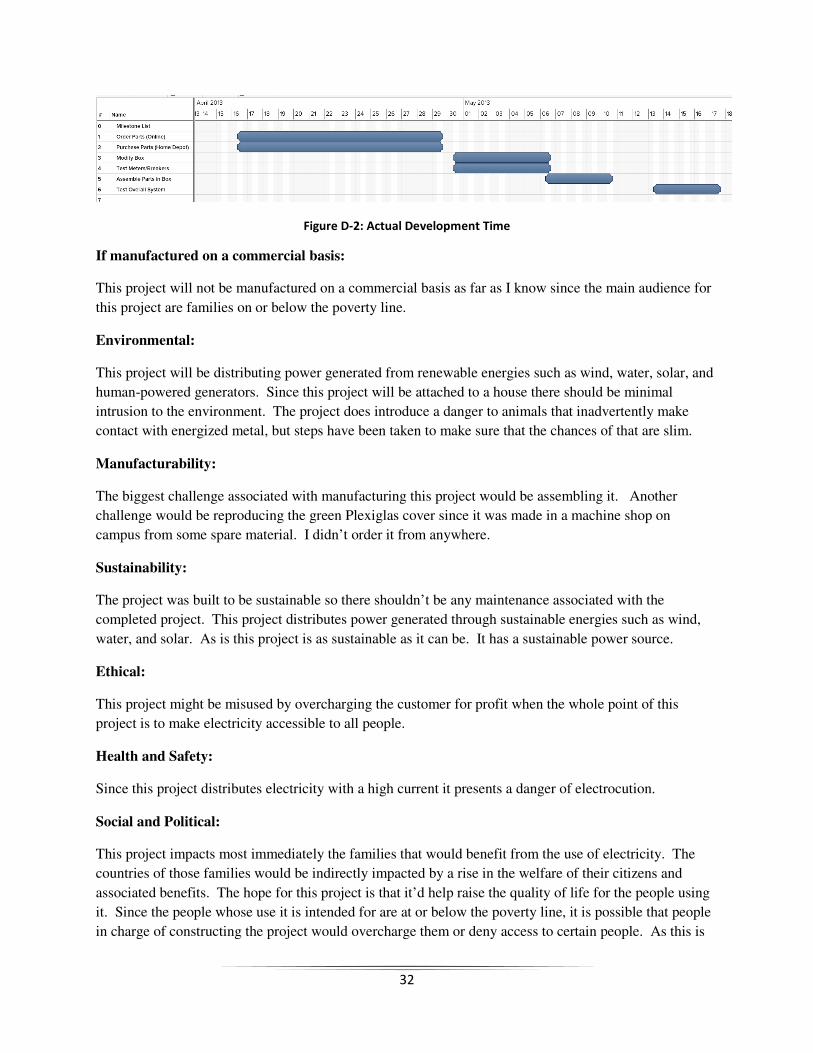
Figure D-2: Actual Development Time
If manufactured on a commercial basis:
This project will not be manufactured on a commercial basis as far as I know since the main audience for
this project are families on or below the poverty line.
Environmental:
This project will be distributing power generated from renewable energies such as wind, water, solar, and
human-powered generators. Since this project will be attached to a house there should be minimal
intrusion to the environment. The project does introduce a danger to animals that inadvertently make
contact with energized metal, but steps have been taken to make sure that the chances of that are slim.
Manufacturability:
The biggest challenge associated with manufacturing this project would be assembling it. Another
challenge would be reproducing the green Plexiglas cover since it was made in a machine shop on
campus from some spare material. I didn’t order it from anywhere.
Sustainability:
The project was built to be sustainable so there shouldn’t be any maintenance associated with the
completed project. This project distributes power generated through sustainable energies such as wind,
water, and solar. As is this project is as sustainable as it can be. It has a sustainable power source.
Ethical:
This project might be misused by overcharging the customer for profit when the whole point of this
project is to make electricity accessible to all people.
Health and Safety:
Since this project distributes electricity with a high current it presents a danger of electrocution.
Social and Political:
This project impacts most immediately the families that would benefit from the use of electricity. The
countries of those families would be indirectly impacted by a rise in the welfare of their citizens and
associated benefits. The hope for this project is that it’d help raise the quality of life for the people using
it. Since the people whose use it is intended for are at or below the poverty line, it is possible that people
in charge of constructing the project would overcharge them or deny access to certain people. As this is
33
partially a humanitarian effort I assume the cost of the project will be paid by the families as well as the
government(s).
Development:
Google SketchUp is a CAD software that was used to make several models in this project.
The process of purchasing circuit breakers was interesting and pretty involved. The manufacturers have
catalogs with codes for the various configurations (colors, switch types, ratings) of each product line.
Manufacturers only take bulk orders though so for this project I had to get in contact with a distributor.
Distributors may have online stores (similar to Amazon), but usually have only common items in stock.
For less common items it was necessary to email a distributor with the manufacturer’s code of the product
I was looking for.
34
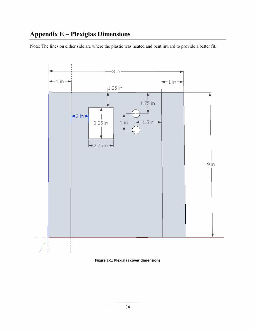
Appendix E – Plexiglas Dimensions
Note: The lines on either side are where the plastic was heated and bent inward to provide a better fit.
Figure E-1: Plexiglas cover dimensions