Embed Size (px)
Citation preview
1
3-Jun-13
DESIGN OF HYBRID MARINE CONTROL SYSTEMS FOR DYNAMIC POSITIONING IN EXTREME SEAS
AND IN ICE
Trong Dong Nguyen
3-Jun-13 2
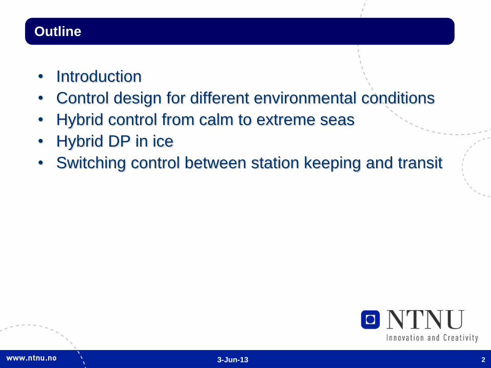
• Introduction
• Control design for different environmental conditions
• Hybrid control from calm to extreme seas
• Hybrid DP in ice
• Switching control between station keeping and transit
Outline
3-Jun-13 3
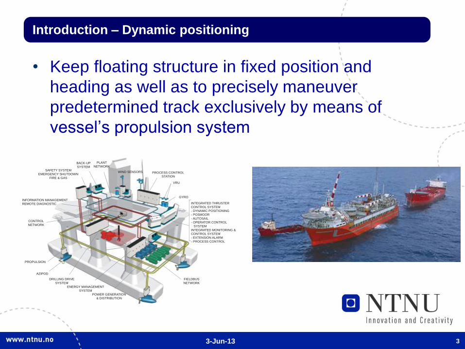
Introduction – Dynamic positioning
• Keep floating structure in fixed position and
heading as well as to precisely maneuver
predetermined track exclusively by means of
vessel’s propulsion system
INTEGRATED THRUSTER
CONTROL SYSTEM
- DYNAMIC POSITIONING
- POSMOOR
- AUTOSAIL
- OPERATOR CONTROL
SYSTEM
INTEGRATED MONITORING &
CONTROL SYSTEM
- EXTENSION ALARM
- PROCESS CONTROL
POWER GENERATION
& DISTRIBUTION
PROCESS CONTROL
STATION
PROPULSION
WIND SENSORS
VRU
GYRO
BACK-UP
SYSTEMSAFETY SYSTEM
EMERGENCY SHUTDOWN
FIRE & GAS
ENERGY MANAGEMENT
SYSTEM
AZIPOD
INFORMATION MANAGEMENT
REMOTE DIAGNOSTIC
DRILLING DRIVE
SYSTEM
PLANT
NETWORK
CONTROL
NETWORK
FIELDBUS
NETWORK
3-Jun-13 4
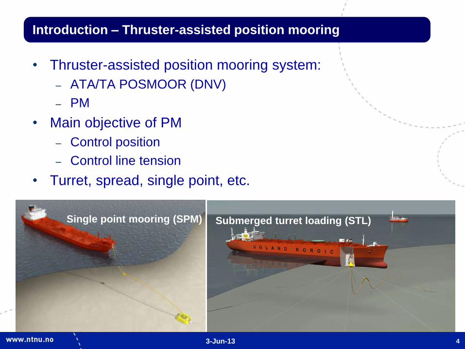
Introduction – Thruster-assisted position mooring
• Thruster-assisted position mooring system:
– ATA/TA POSMOOR (DNV)
– PM
• Main objective of PM
– Control position
– Control line tension
• Turret, spread, single point, etc.
Single point mooring (SPM) Submerged turret loading (STL)
3-Jun-13 5
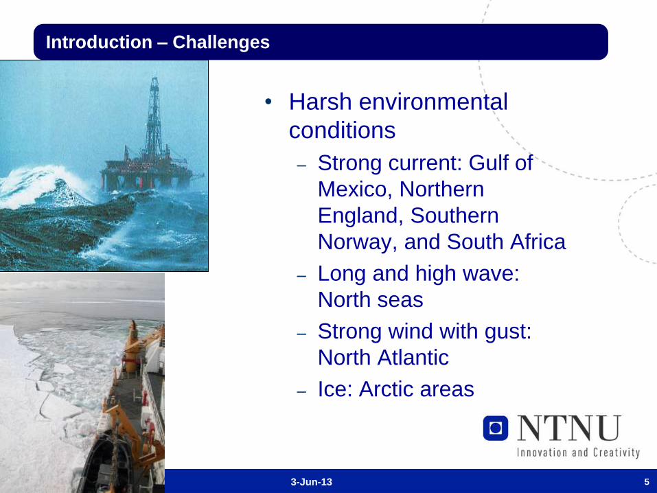
Introduction – Challenges
• Harsh environmental
conditions
– Strong current: Gulf of
Mexico, Northern
England, Southern
Norway, and South Africa
– Long and high wave:
North seas
– Strong wind with gust:
North Atlantic
– Ice: Arctic areas
3-Jun-13 6
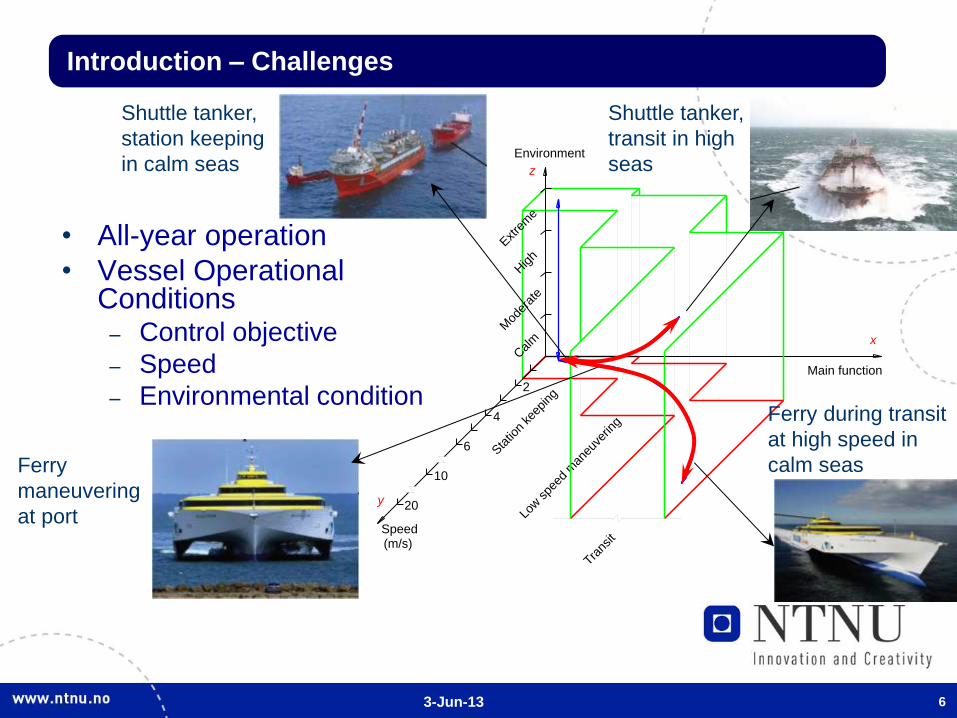
• All-year operation
• Vessel Operational Conditions
– Control objective
– Speed
– Environmental condition
Trans
it
Low spe
ed m
aneu
verin
g
Mod
erat
e
10
(m/s)Speed
y 20
Calm
Sta
tion
keep
ing
2
6
4
High
Extre
me
Environment
z
Main function
x
Shuttle tanker,
station keeping
in calm seas
Shuttle tanker,
transit in high
seas
Ferry during transit
at high speed in
calm seas Ferry
maneuvering
at port
Introduction – Challenges

3-Jun-13 7
Introduction – Hybrid concept motivation
• Design of control system for changes of vessel
operational conditions (VOCs)
• One unique nonlinear controller
– complicated or maybe impossible
– difficult to satisfy many control objectives
• Hybrid controller (combine and switch among
different controllers)
– simpler solution
– satisfy different control objectives
3-Jun-13
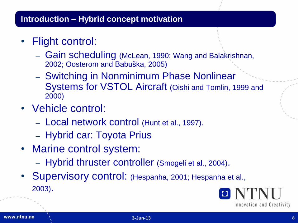
Introduction – Hybrid concept motivation
• Flight control:
– Gain scheduling (McLean, 1990; Wang and Balakrishnan, 2002; Oosterom and Babuška, 2005)
– Switching in Nonminimum Phase Nonlinear Systems for VSTOL Aircraft (Oishi and Tomlin, 1999 and 2000)
• Vehicle control:
– Local network control (Hunt et al., 1997).
– Hybrid car: Toyota Prius
• Marine control system:
– Hybrid thruster controller (Smogeli et al., 2004).
• Supervisory control: (Hespanha, 2001; Hespanha et al.,
2003).
8

3-Jun-13 9
Marine Control System Structure
(Sørensen, 2005)
Ship 1: Operational management
Local optimization (min-hour)
Plant control
Actuator control
R
eal-
Tim
e N
etw
ork
Off
ice N
etw
ork
Business enterprise/ Fleet management
Ship 2: Ship 3:
Control layers
High level (0.1-5 s)
Low level (0.001-1 s)
Real-Time Control
Office Systems
Fau
lt-T
ole
ran
t C
on
tro
l • Guidance systems
• Optimal setpoint chasing
• Plant diagnostics and condition monitoring
• DP control
• Power management
• Ballast control
• Supply chain management
• Thruster control
• Motor and drive control
Control design
3-Jun-13 10
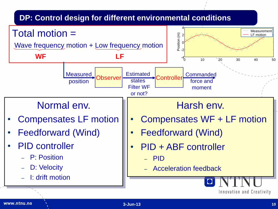
DP: Control design for different environmental conditions
Total motion =
Measured
position Observer
Estimated
states
0 10 20 30 40 50 -4
-2
0
2
4
Po
sitio
n (
m) Measurement
LF motion
Controller Commanded
force and
moment
Wave frequency motion + Low frequency motion
WF LF
Normal env.
• Compensates LF motion
• Feedforward (Wind)
• PID controller – P: Position
– D: Velocity
– I: drift motion
Harsh env.
• Compensates WF + LF motion
• Feedforward (Wind)
• PID + ABF controller – PID
– Acceleration feedback
Filter WF
or not?
3-Jun-13 11
Mod
erat
e
2
Sta
tion
keep
ing
Calm
Low spe
ed m
aneu
verin
g
10
Speed(m/s)
y 20
6
4
Trans
it
Main function
x
Environment
Extre
me
High
z
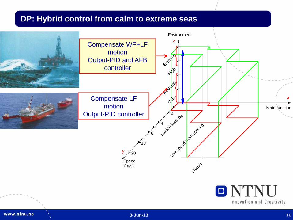
DP: Hybrid control from calm to extreme seas
Compensate LF
motion
Output-PID controller
Compensate WF+LF
motion
Output-PID and AFB
controller
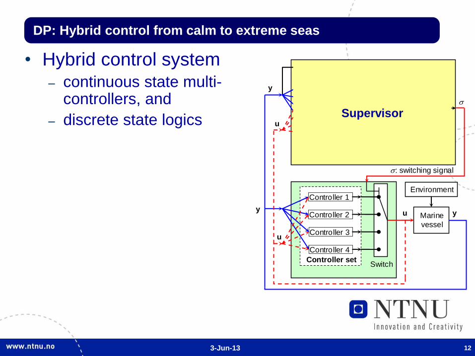
3-Jun-13 12
• Hybrid control system – continuous state multi-
controllers, and
– discrete state logics
Controller 4
Controller 3
ep
: switching signal
y Marine
vessel
Environment
u
Model 1
Model 2
Model 3
Supervisor
Model set
y
y
Controller set
Switch
Controller 1
Controller 2
u
u
Model 4
Operator
Supervisory
control
Decision
Supervisor
DP: Hybrid control from calm to extreme seas

3-Jun-13 13
• Models/Estimators
– Input: y, u, w0p
– Output: yp
Controller 4
Controller 3
ep
: switching signal
y Marine
vessel
Environment
u
Model 1
Model 2
Model 3
Supervisor
Model set
y
y
Controller set
Switch
Controller 1
Controller 2
u
u
Model 4
Operator
Supervisory
control
Decision
DP: Switching control from calm to extreme seas
Model i
y
u
w0p
y yp
ep
3-Jun-13 14
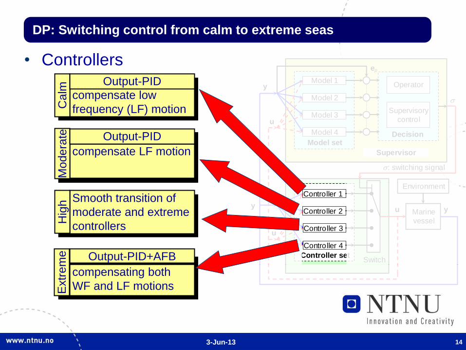
• Controllers
DP: Switching control from calm to extreme seas
Controller 4
Controller 3
ep
: switching signal
y Marine
vessel
Environment
u
Model 1
Model 2
Model 3
Supervisor
Model set
y
y
Controller set
Switch
Controller 1
Controller 2
u
u
Model 4
Operator
Supervisory
control
Decision
compensate low
frequency (LF) motion
compensate LF motion
compensating both
WF and LF motions
Smooth transition of
moderate and extreme
controllers
Calm
M
odera
te
Hig
h
Extr
em
e
Output-PID
Output-PID
Output-PID+AFB
3-Jun-13 15
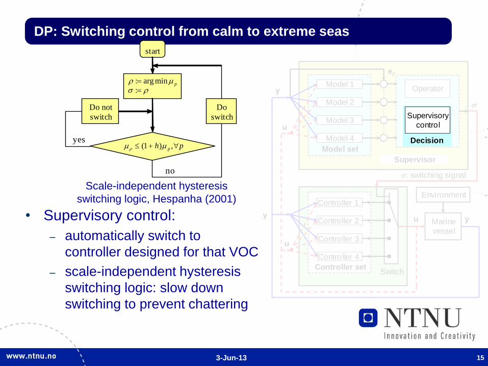
• Supervisory control:
– automatically switch to
controller designed for that VOC
– scale-independent hysteresis
switching logic: slow down
switching to prevent chattering
DP: Switching control from calm to extreme seas
yes
start
: arg min
:p
(1 ) ,ph p
no
Do not
switch
Do
switch
Scale-independent hysteresis
switching logic, Hespanha (2001)
Controller 4
Controller 3
ep
: switching signal
y Marine
vessel
Environment
u
Model 1
Model 2
Model 3
Supervisor
Model set
y
y
Controller set
Switch
Controller 1
Controller 2
u
u
Model 4
Operator
Supervisory
control
Decision
3-Jun-13 16
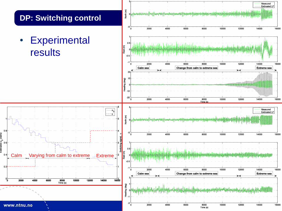
DP: Switching control
• Experimental
results
Calm Varying from calm to extreme Extreme
3-Jun-13 17
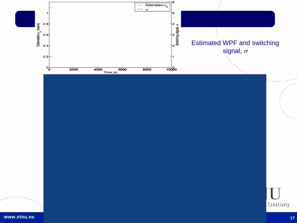
Experiment – Set 2
Estimated WPF and switching
signal,
3-Jun-13 18
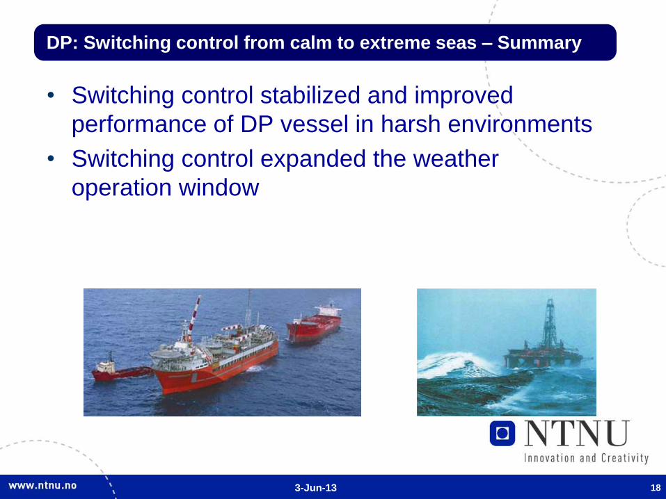
• Switching control stabilized and improved
performance of DP vessel in harsh environments
• Switching control expanded the weather
operation window
DP: Switching control from calm to extreme seas – Summary

3-Jun-13 19
DP in ice
• Motivation
– Oil demand
– Oil reservation in Arctic area
– Global warming
3-Jun-13 20
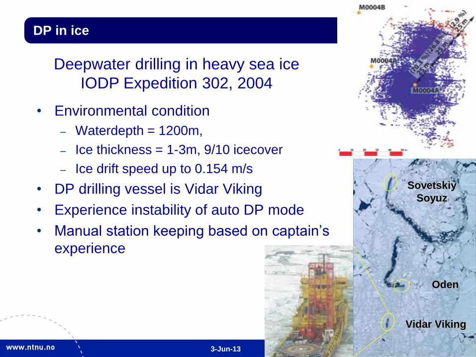
DP in ice
• Environmental condition
– Waterdepth = 1200m,
– Ice thickness = 1-3m, 9/10 icecover
– Ice drift speed up to 0.154 m/s
• DP drilling vessel is Vidar Viking
• Experience instability of auto DP mode
• Manual station keeping based on captain’s
experience
Sovetskiy
Soyuz
Oden
Vidar Viking
Deepwater drilling in heavy sea ice
IODP Expedition 302, 2004
3-Jun-13 21
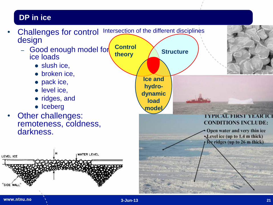
DP in ice
• Challenges for control design
– Good enough model for ice loads slush ice,
broken ice,
pack ice,
level ice,
ridges, and
Iceberg
• Other challenges: remoteness, coldness, darkness.
Control
theory Structure
Ice and
hydro-
dynamic
load
model
Intersection of the different disciplines
3-Jun-13 22
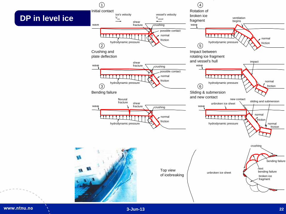
DP in level ice
©2007 by Nguyen
hydrodynamic pressure
shearwave crushing
normal
friction
fracture
hydrodynamic pressure
flexural
shearwave crushing
fracture
fracture
hydrodynamic pressure
ventilation
wave
begins
possible contact
hydrodynamic pressure
shearwave crushing
normal
friction
fracture
possible contact
normal
friction
normal
friction
hydrodynamic pressure
sliding and submersion
wave
Initial contact
Crushing and
Bending failure
Rotation of
Impact between
plate deflection
broken ice
rotating ice fragment
fragment
and vessel's hull
normal
friction
hydrodynamic pressure
impact
wave
Sliding & submersion
and new contact
normal
friction
normalfriction
V Vice's velocity vessel's velocity
ice vessel
crushing
bending failure
nextbending failure
unbroken ice sheet
new contact
unbroken ice sheet
broken icefragment
1
2
3
4
5
6
Top view
of icebreaking
3-Jun-13 23
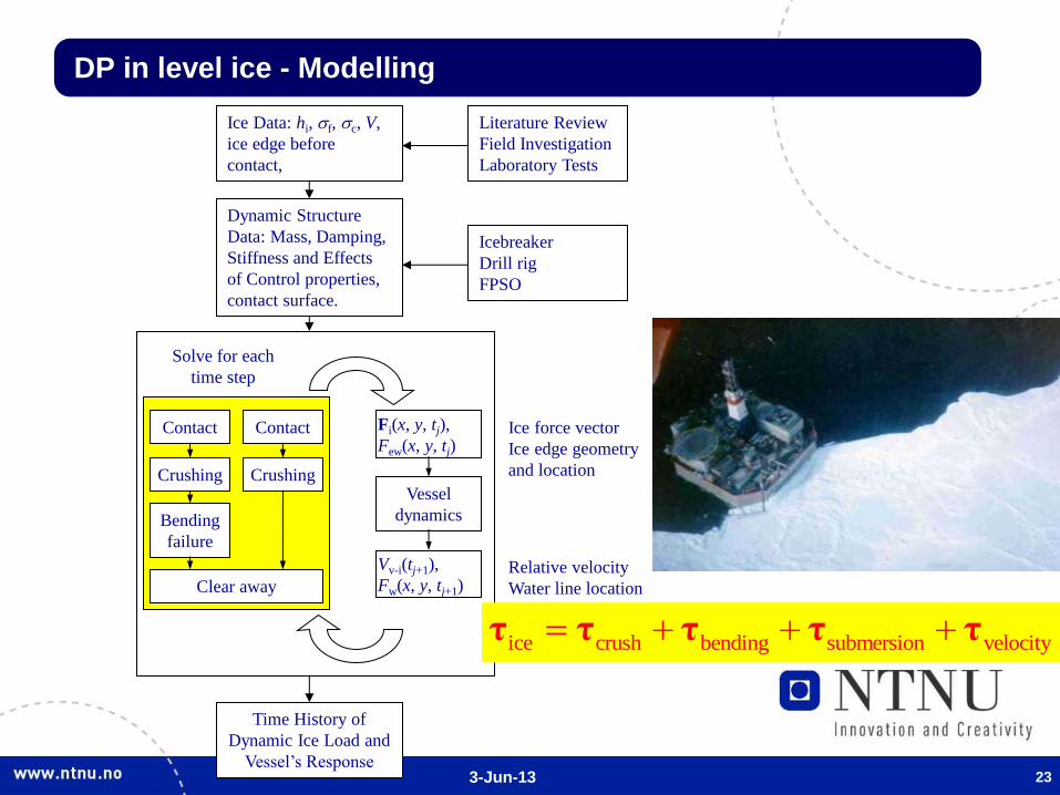
DP in level ice - Modelling
Ice Data: hi, f, c, V,
ice edge before
contact,
Dynamic Structure
Data: Mass, Damping,
Stiffness and Effects
of Control properties,
contact surface.
Contact
Time History of
Dynamic Ice Load and
Vessel’s Response
Vessel
dynamics
Literature Review
Field Investigation
Laboratory Tests
Icebreaker
Drill rig
FPSO
Solve for each
time step
Fi(x, y, tj),
Few(x, y, tj)
Vv-i(tj+1),
Fw(x, y, tj+1)
Ice force vector
Ice edge geometry
and location
Relative velocity
Water line location
Crushing
Bending
failure
Clear away
Contact
Crushing
ice crush bending submersion velocityτ τ τ τ τ
3-Jun-13
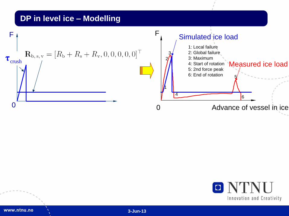
DP in level ice – Modelling
F
Advance of vessel in ice0
1
2
3
4
5
6
1: Local failure
2: Global failure
3: Maximum
4: Start of rotation
5: 2nd force peak
6: End of rotation
crushτ
F
0
Simulated ice load
Measured ice load
3-Jun-13
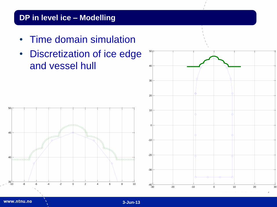
DP in level ice – Modelling
• Time domain simulation
• Discretization of ice edge
and vessel hull
-30 -20 -10 0 10 20 30-40
-30
-20
-10
0
10
20
30
40
50
-10 -8 -6 -4 -2 0 2 4 6 8 1035
40
45
50

3-Jun-13
DP in level ice – Modelling
• Validation
– MESH 6: Comparison between mean simulated
ice load and empirical ice resistance for different
ice thicknesses and ice velocities.
3-Jun-13
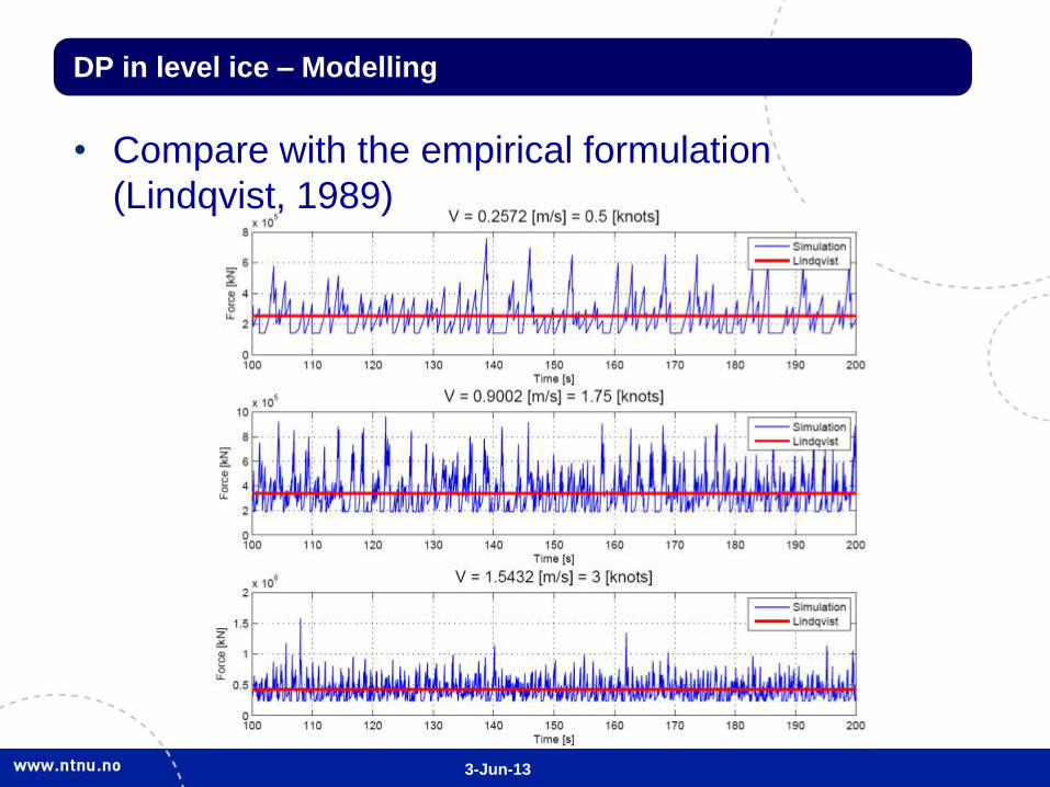
DP in level ice – Modelling
• Compare with the empirical formulation
(Lindqvist, 1989)

3-Jun-13
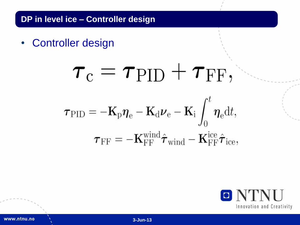
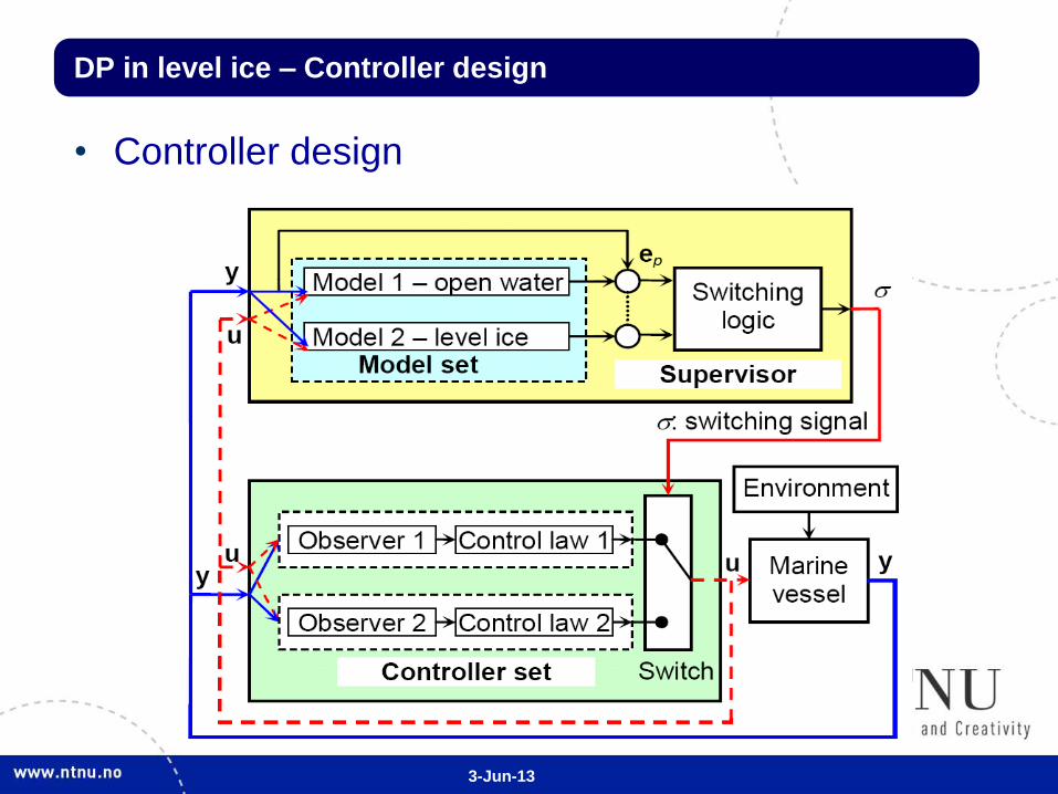
DP in level ice – Controller design
• Control plant model for open water and ice
• Observer design for open water and ice
Without ice-load
measurements With ice-load
measurements
3-Jun-13
DP in level ice – Controller design
• Controller design
3-Jun-13
DP in level ice – Controller design
• Controller design
3-Jun-13
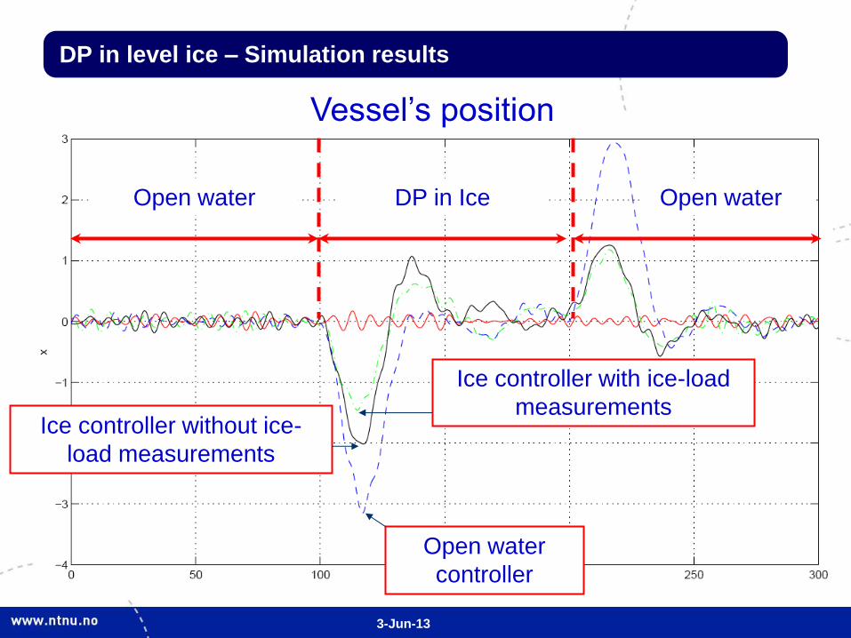
DP in level ice – Simulation results
Open water
controller
Ice controller without ice-
load measurements
Ice controller with ice-load
measurements
Vessel’s position
Open water DP in Ice Open water
3-Jun-13 34
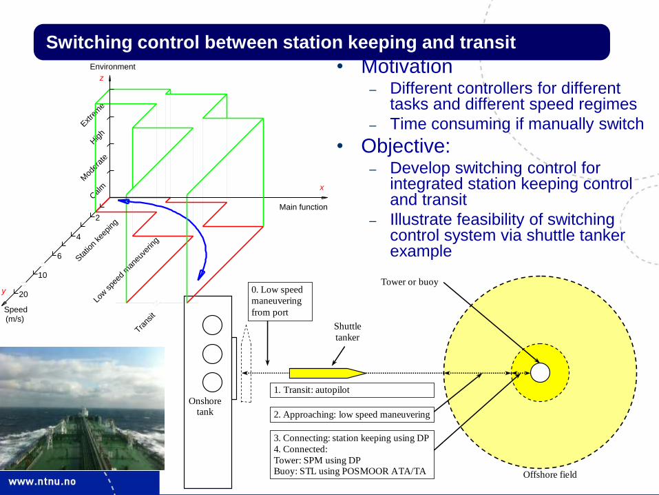
Switching control between station keeping and transit
Onshore tank
Shuttle
tanker
1. Transit: autopilot
2. Approaching: low speed maneuvering
3. Connecting: station keeping using DP
4. Connected:
Tower: SPM using DP Buoy: STL using POSMOOR ATA/TA
Tower or buoy
Offshore field
0. Low speed
maneuvering
from port
• Motivation – Different controllers for different
tasks and different speed regimes
– Time consuming if manually switch
• Objective: – Develop switching control for
integrated station keeping control and transit
– Illustrate feasibility of switching control system via shuttle tanker example
4
Sta
tion
keep
ing
10
20
Speed(m/s)
y
6
Low spe
ed m
aneu
verin
g
Trans
it
Calm
2
Extre
me
High
Environment
z
x
Main function
Mod
erat
e
3-Jun-13 35
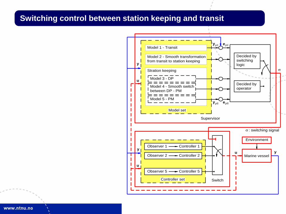
Switching control between station keeping and transit
Model 1 - Transit
Model 2 - Smooth transformation
Stration keeping
Model 3 - DP
Model 4 - Smooth switch
Model 5 - PM
from transit to station keeping
between DP - PM
Model set
Supervisor
Decided by
Decided by
switching
operator
logic
Observer 1 Controller 1
Controller 2Observer 2
Controller 5Observer 5
Controller set Switch
Marine vessel
Environment
: switching signal
u
y ep1 p1
y
u
u
y
y
p5eyp5
3-Jun-13 36
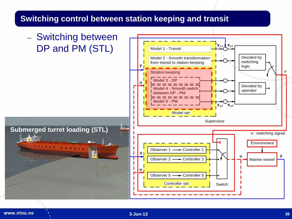
Switching control between station keeping and transit
– Switching between
DP and PM (STL) Model 1 - Transit
Model 2 - Smooth transformation
Stration keeping
Model 3 - DP
Model 4 - Smooth switch
Model 5 - PM
from transit to station keeping
between DP - PM
Model set
Supervisor
Decided by
Decided by
switching
operator
logic
Observer 1 Controller 1
Controller 2Observer 2
Controller 5Observer 5
Controller set Switch
Marine vessel
Environment
: switching signal
u
y ep1 p1
y
u
u
y
y
p5eyp5
Submerged turret loading (STL)
3-Jun-13 37
Switching control between station keeping and transit
3-Jun-13
End of Presentation
• List of reference: – Nguyen H. D., Nguyen T. D., Quek S. T. and Sørensen A. J. (2011). Position-moored
drilling vessel in level ice by control of riser end angles. Journal of Cold Regions
Science and Technology, 66(2-3), pp 65–74.
– Nguyen T. D. and Sørensen A. J. (2009). Switching Control for Thruster-Assisted
Position Mooring System. Control Engineering Practice, 17(9), pp. 985–994.
– Nguyen T. D. and Sørensen A. J. (2009). Setpoint chasing for thruster-assisted
position mooring. IEEE Journal of Oceanic Engineering, 34(4), pp 548–558.
– Nguyen T. D., Sørensen A. J. and Quek S. T. (2008). Multi-Operational Hybrid
Controller Structure for Station Keeping and Transit Operations of Marine Vessels.
IEEE Transactions on Control Systems Technology, 16(3), pp. 491–498.
– Nguyen T. D., Sørensen A. J. and Quek S. T. (2007). Design of High Level Hybrid
Controller for Dynamic Positioning from Calm to Extreme Sea Conditions. Automatica,
43(5), pp. 768–785.
– Hassani, V., Sørensen A. J., Pascoal A. M. and Nguyen T. D. (2012). Multiple Model
Adaptive Dynamic Positioning. In Proc. MCMC’2012, 9th IFAC Conference on
Manoeuvring and Control of Marine Craft, Arenzano, Italy, 19-21 September.
– Nguyen, T. D., Sørbø A. H. and Sørensen A. J. (2009). Modelling and Control for
Dynamic Positioned Vessels in Level Ice. In Proceedings of 8th Conference on
Manoeuvring and Control of Marine Craft (MCMC’2009), pp. 229-236, September 16-
18, Guarujá, Brazil.
38
©2007 by Nguyen