Embed Size (px)
Citation preview

1
DESIGN OF HUMAN FACIAL FEATURE
RECOGNITION SYSTEM
A THESIS SUBMITTED IN PARTIAL FULFILMENT OF THE REQUIREMENTS FOR THE DEGREE OF
Bachelor of Technology in Electrical Engineering
By
Prakash Mallick 108EE009
Ashish Ankur
108EE064
Department of Electrical Engineering
National Institute of Technology, Rourkela 2012

2
DESIGN OF HUMAN FACIAL FEATURE
RECOGNITION SYSTEM
A THESIS SUBMITTED IN PARTIAL FULFILMENT OF THE REQUIREMENTS FOR THE DEGREE OF
Bachelor of Technology in Electrical Engineering
By
Prakash Mallick 108EE009
Ashish Ankur
108EE064
Under the Supervision of
Prof. Dipti Patra,
Department of Electrical Engineering National Institute of Technology, Rourkela
Department of Electrical Engineering
National Institute of Technology, Rourkela 2012

3
Department of Electrical Engineering National Institute of Technology
Rourkela - 769008 2012
CERTIFICATE
This is to certify that the thesis entitled, “Design Of Human Facial Feature Recognition
System” submitted by PRAKASH MALLICK (108EE009) and ASHISH ANKUR
(108EE064) in partial fulfillment of the requirements for the award of Bachelor of Technology
Degree in Electrical Engineering at the National Institute of Technology, Rourkela (Deemed
University) is an authentic work carried out by them under my supervision and guidance.
To the best of my knowledge, the matter embodied in the thesis has not been submitted to any
other University / Institute for the award of any Degree or Diploma.
Professor Dipti Patra
Date:
Department of Electrical Engineering
National Institute of Technology Rourkela – 769008

4
ACKNOWLEDGEMENT
We would like to articulate our profound gratitude and indebtedness to those persons who
helped us in the project.
First and foremost, we would like to convey our obligation to our project guide Prof.
Dipti Patra, (Associate Professor, Department of Electrical Engineering, National Institute of
Technology, Rourkela), for her constant motivation, help and support. We are sincerely thankful
to her for her esteemed guidance and pain taking effort in improving our understanding on the
topic.
Last but not the least; we would like to thank our teachers and parents for their blessings
and well wishes.
Prakash Mallick (108EE009)
Ashish Ankur (108EE064)
Department of Electrical Engineering,
NIT Rourkela

5
ABSTRACT
Augmenting human computer interaction with automated analysis and synthesis of
facial expressions is the goal towards which much research effort has been devoted to
in the last few years. Facial feature recognition is one of the important aspects of natural
human-machine interfaces; it has great applications such as in behavioral science,
security systems and in clinical practice. Although humans recognize facial expressions
virtually without effort or delay, reliable expression recognition by machine is still a
challenging task. The face expression recognition problem is challenging because
different individuals display the same expression differently. In this project we are trying
to design a facial feature recognition system in real time using the concepts of Haar
classifiers, contour concepts, template matching and studying some models related to it.
We have tried to first extract face region from the video using above mentioned
approach and had tried to extract some facial features and locate their position in the
image.

6
TABLE OF CONTENTS
CERTIFICATE .................................................................................................................................................... 3
ACKNOWLEDGEMENT .................................................................................................................................... 4
ABSTRACT.......................................................................................................................................................... 5
TABLE OF CONTENTS ..................................................................................................................................... 6
LIST OF FIGURES.............................................................................................................................................. 7
CHAPTER I: INTRODUCTION ......................................................................................................................... 8
CHAPTER II: BACKGROUND AND LITERATURE REVIEW ...................................................................... 9
1. Knowledge based methods- ............................................................................................................................. 9
2. Feature-invariant methods-.............................................................................................................................. 9
3. Template matching methods- ........................................................................................................................ 10
4. Appearance-based methods ........................................................................................................................... 10
FEATURE DETECTION USING HAAR LIKE FEATURES- .......................................................................... 11
FEATURE TYPES AND EVALUATION:- ...................................................................................................... 12
THE ADABOOST MACHINE LEARNING METHOD:- ................................................................................. 13
THE CONTOUR CONCEPT:- ......................................................................................................................... 15
FACIAL FEATURE EXTRACTION USING ASM:- ....................................................................................... 16
CHAPTER III: METHODOLOGY ................................................................................................................... 19
Implementing Haar concept- ............................................................................................................................. 19
PROPOSING A NEW FACE LANDMARKING CONCEPT- .......................................................................... 26
CHAPTER IV: RESULTS ................................................................................................................................. 31
CHAPTER V: CONCLUSION .......................................................................................................................... 34
REFERENCES ................................................................................................................................................... 35
APPENDIX ......................................................................................................................................................... 36

7
LIST OF FIGURES
Fig. 1 Examples of Haar features used
Fig. 2 Picture showing that the pixel value at (x,y),contains the sum of all pixel values within
rectangular region that has one corner at the top left of the image and the other at location
(x,y).
Fig. 3 AdaBoost classifiers as a filter chain
Fig. 4 The mean face (black) with variations of the first principal component (gray).
Fig. 5 Face Detection Using Haar classifiers
Fig. 6 Edge detection of face using Canny Edge detector
Fig. 7 Contour drawn over the face
Fig. 8 Contour converted to rectangles along with their center point
Fig. 9 Landmarked image of face showing boundaries of eyes, nose and mouth.
Fig. 10 Template of eye region
Fig. 11 Eye region detected using Template matching
Fig. 12 Face and Eye detected using Haar Classifiers
Fig. 13 Lip region extracted using Contour concept
Fig. 14 Enlarged Lip region extracted to show surprise

8
CHAPTER I: INTRODUCTION
Facial gesture recognition is a very important and natural way of human-computer interaction.
But developing a gesture based interaction system which is equally efficient as humans is a great
challenge.
Facial gesture recognition is based on facial features recognition and face detection. So in order
to start facial gesture recognition we have to first completely and accurately detect the face
features as like nose, mouth, eyes and the distance between the each other.
We have to concentrate on various face detection techniques because in facial gesture
recognition the basic steps involved are:-
1. Face Finding
2. Facial Feature Detection
3. Facial Gesture Recognition
The aim of our project is to design a facial feature recognition system in real time. So, we have
to study various techniques of face finding and facial feature detection, and then we have to
proceed for facial gesture recognition. As gesture recognition is a very complicated study, we are
mainly concentrating on facial feature extraction and location as a part of this project.

9
CHAPTER II: BACKGROUND AND LITERATURE REVIEW
The various methods used for face detection may be classified in the following categories [1]
:-
1. Knowledge based methods- They are rule-based methods that encode our knowledge of
human faces.
2. Feature-invariant methods- These methods are algorithms that find invariant features of
face despite its angle or position.
3. Template matching methods. These algorithms compare input images with stored
patterns of faces or features.
4. Appearance-based methods. A template matching method whose pattern database is
learnt from a set of training images.
1. Knowledge based methods-
These are rule-based methods. They try to capture our knowledge of faces, and translate
them into a set of rules. It’s easy to guess some simple rules. For example, a face usually has two
symmetric eyes, and the eye area is darker than the cheeks. Facial features could be the distance
between eyes or the color intensity difference between the eye area and the lower zone. The big
problem with these methods is the difficulty in building an appropriate set of rules. There could
be many false positives if the rules were too general. On the other hand, there could be many
false negatives if the rules were too detailed. A solution is to build hierarchical knowledge-based
methods to overcome these problems. However, this approach alone is very limited.
2. Feature-invariant methods-
In this method we try to find some invariant features for face detection. The idea is to
overcome the limits of our instinctive knowledge of faces. In this method we firstly, triy to find
eye-analogue pixels, so it removes unwanted pixels from the image. After performing the

10
segmentation process, they consider each eye-analogue segment as a candidate of one of the
eyes. Then, a set of rule is executed to determinate the potential pair of eyes. Once the eyes are
selected, the algorithm calculates the face area as a rectangle. The four vertexes of the face are
determined by a set of functions. So, the potential faces are normalized to a fixed size and
orientation. Then, the face regions are verified using a back propagation neural network.
3. Template matching methods-
Template matching methods try to define a face as a function. We try to find a standard template
of all the faces. Different features can be defined independently. For example, face can be
divided into eyes, face contour, nose and mouth. Other templates use the relation between face
regions in terms of brightness and darkness. These standard patterns are compared to the input
images to detect faces. It cannot achieve good results with variations in pose, scale and shape.
In our program we defined the template of our eye as a feature and tried to find the facial region
based upon that. The detection is based on template matching and after matching the template,
histogram is done for the real time image inside the rectangle which depicts the intensities. This
approach is simple to implement, but it is not adequate for face detection.
4. Appearance-based methods
The templates in appearance-based methods are learned from the examples in the images. In
general, appearance-based methods rely on techniques from statistical analysis and machine
learning to find the relevant characteristics of face images.
Some appearance-based methods work in a probabilistic network. An image or feature vector is a
random variable with some probability of belonging to a face or not. Another approach is to
define a discriminant function between face and non-face classes. Taking into account
recognition we categorize images of two kinds:-

11
1. Positive images
2. Negative images
Positive images are those kinds of images that relate to the particular image we want to
recognize. Negative images are all those images except the required images. Using the positive
and negative images we create a database of a particular feature which is used to compare with a
real time video and it finds the similar feature in that. The details of this approach are elaborated
later in the methodology chapter.
FEATURE DETECTION USING HAAR LIKE FEATURES-
Any image is just a collection of color and/or light intensity values. Analyzing these pixel values
for face detection is a difficult task as the face image consists of wide variation of shape and
pigmentation. In 2001, Viola and Jones devised an algorithm which utilized the Haar-like
features[2]
for facial feature detection instead of analyzing the pixels, as they were complex and
consumed more time. Haar features are digital image features used in object recognition. They
owe their name to the similarity with Haar wavelets. A Haar-like feature considers adjacent
rectangular regions at a specific location in a detection window, sums up the pixel intensities in
these regions and calculates the difference between them. This difference is then used to
categorize subsections of an image. For example, let us say we have an image database with
human faces. It is a common observation that among all faces the region of the eyes is darker
than the region of the cheeks. Therefore a common Haar feature for face detection is a set of two
adjacent rectangles that lie above the eye and the cheek region. The position of these rectangles
is defined relative to a detection window that acts like a bounding box to the target object (the
face in this case). In the detection part of the Viola–Jones object detection, a window of the
target size is moved over the input image, and for each part of the image the Haar-like feature is

12
calculated. This difference is then compared to a learned threshold that separates non-objects
from objects. Because such a Haar-like feature is only a weak classifier a large number of Haar-
like features are necessary to describe an object with accuracy. In the Viola–Jones object
detection framework, the Haar-like features are therefore organized in something called a
classifier cascade to form a strong learner or classifier. Therefore one uses cascade classifiers as
it improves performance and accuracy.
FEATURE TYPES AND EVALUATION:-
The features that Viola and Jones[4]
used are based on Haar wavelets. Haar wavelets are basically
single wavelength square waves (one having high interval and another low interval).In two
dimension ,a square wave is a pair of adjacent rectangle of which one is light and other is dark.
However, since the features used by Viola and Jones rely on more than one rectangular area, they
are generally more complex. There are basically four types of feature types used
a. Two 2-rectangle feature (one horizontal and other vertical).
b. One 3-rectangle feature.
c. One 4-rectangle feature
These features are shown in figure 1.
Fig. 1 Examples of Haar features used
13
The features used for the detection framework involve the sum of pixel values within rectangular
areas. The value of any feature is always simply the sum of pixels within clear rectangles
subtracted from the sum of pixel within shaded rectangles. Nowadays rectangle features of this
kind are rather primitive to use as many alternatives such as steerable filters has been developed.
The presence of a Haar feature is determined by subtracting the average dark-region pixel value
from the average light-region pixel value. If the difference is above a threshold (set during
learning), that feature is said to be present. With the use of a typical kind of image representation
called as integral image with the rectangular features it is seen that the feature evaluation is a
considerably faster. To determine the presence or absence of hundreds of Haar features at every
image location and at several scales efficiently, Viola and Jones used Integral Image. Generally
“integrating” means summing up all the small units together. Here the small units are the pixel
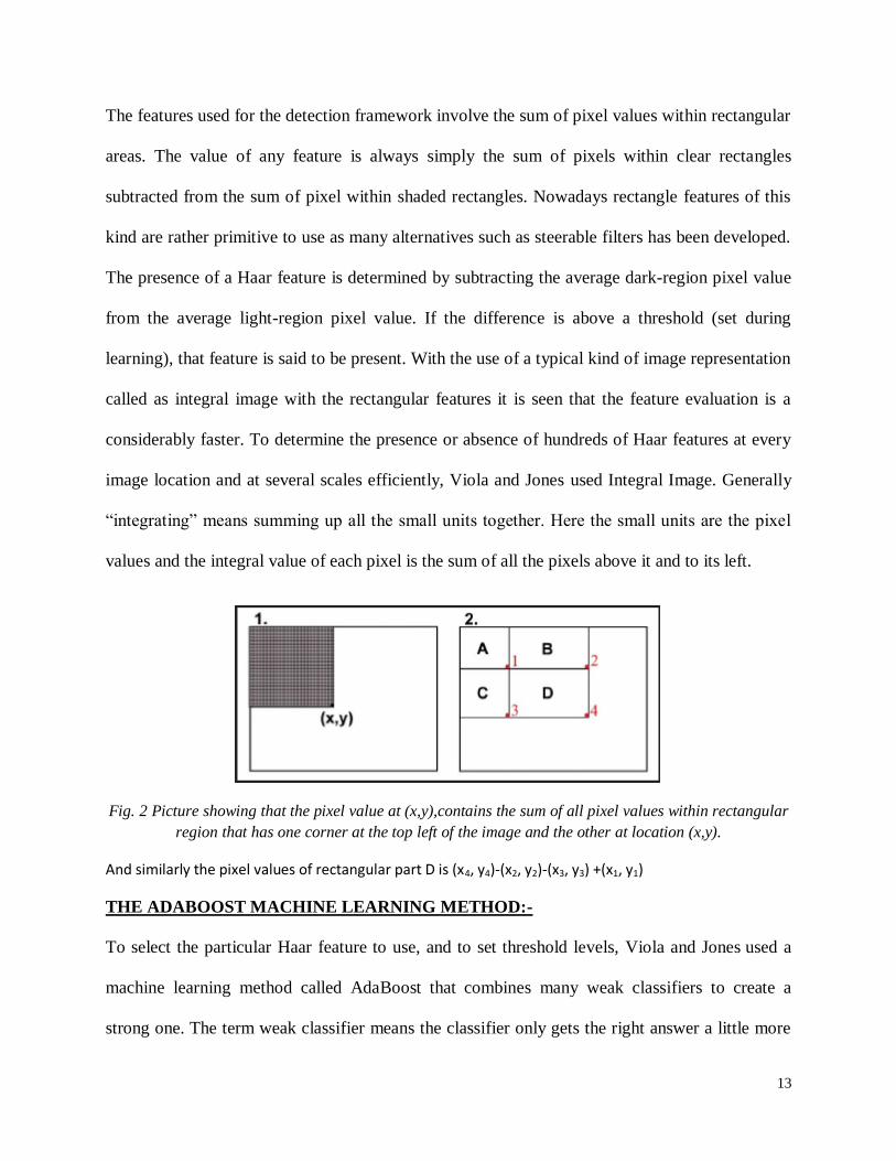
values and the integral value of each pixel is the sum of all the pixels above it and to its left.
Fig. 2 Picture showing that the pixel value at (x,y),contains the sum of all pixel values within rectangular
region that has one corner at the top left of the image and the other at location (x,y).
And similarly the pixel values of rectangular part D is (x4, y4)-(x2, y2)-(x3, y3) +(x1, y1)
THE ADABOOST MACHINE LEARNING METHOD:-
To select the particular Haar feature to use, and to set threshold levels, Viola and Jones used a
machine learning method called AdaBoost that combines many weak classifiers to create a
strong one. The term weak classifier means the classifier only gets the right answer a little more

14
often than random guessing would and this is not very good. But if you have a lot of these weak
classifiers, and each one would push the final answer a little bit in the right direction, you'd have
a combined force for arriving at the correct solution. AdaBoost selects a set of weak classifiers to
combine and assigns a weight to each.
Fig. 3 AdaBoost classifiers as a filter chain
Viola and Jones combined a series of AdaBoost classifiers as a filter chain as kind of shown in
the Figure3. Each filter is categorised as a separate AdaBoost classifier with a fairly small
number of weak classifiers. The threshold at each level is set low enough to pass all or nearly
most face in training set. The filters at each level are trained to classify training images that
passed all previous stages. (The training set is a large database of faces, maybe a thousand or
two).If any one of these filters fails to pass an image region, that region is immediately classified
as face.

15
THE CONTOUR CONCEPT:-
A contour [3]
is a list of points that represent, in one way or another, a curve in an image.
Qualitatively, edges occur at boundaries between regions of different color, intensity, or texture.
Unfortunately, segmenting an image into coherent regions is a difficult task. Often, it is
preferable to detect edges using only purely local information. Under such conditions, a
reasonable approach is to define an edge as a location of rapid intensity variation. Think of an
image as a height field. On such a surface, edges occur at locations of steep slopes, or
equivalently, in regions of closely packed contour lines (on a topographic map).
Contour tracing is defined as one of many preprocessing techniques (the techniques involved
before the actual image processing is done or started) used on digital images in order to extract
the information about the general shape of the objects in the image. As the contour is extracted of
a given pattern, its different characteristics will be explained and used as features which will later
be used to classify pattern. Therefore, the correct extraction of contours will produce more
efficient and accurate features which can be marked with different markers(in our case rectangles
or circles).As a result of this chances are increased for correctly classifying pattern. The contour
pixels are generally a small subset of the total number of pixels representing a pattern. Whenever
we run feature extracting algorithm on the contour instead of the whole pattern the amount of
computation time is greatly reduced. Since the contour shares many features with the initial
pattern, the feature extraction process becomes much more efficient when performed on the
contour rather on the original pattern.
So, we can use contour tracing as a major contributor to the efficiency of the feature extraction
process.

16
FACIAL FEATURE EXTRACTION USING ASM:-
Active Shape Models [6,7]
(ASM) is one method of facial feature extraction that uses a statistical
approach. ASM uses a flexible model that can be deformed according to parameters of the
distribution of training data points. ASM perform a search feature in the image of the tested
capitalize point distribution model. Point distribution model is the statistical models obtained
from learning outcomes in the distribution of the points in a vector data set of training. With the
point distribution model, a form that is acceptable can be built from the model form. Thus, each
image in the training set can be approximated using:
where is the vector average model of the form, is t eigenvectors of
the covariance matrix, is the parameter of the model flexible in the form of t-dimensional
vector, and t is a significant amount of the first eigenvalue. There are a variety of approaches can
be used to search features, ranging from very simple to the complex or even a combinat ion of
several approaches. Various approaches search feature is a modification of the initial step in the
ASM algorithm as follows:
1. Check the area around each point on the model form of reference to find a position that
matches the closest point on the model of the target. (The points derived from the vector which is
calculated using the parameters. For the initial value 0)
2. Update the parameters of the flexible model in the form of t-dimensional vector and
transformation parameter to match with the new point.
3. Do the restrictions on parameters to ensure that the resulting shape model is a model form that
can be accepted.
17
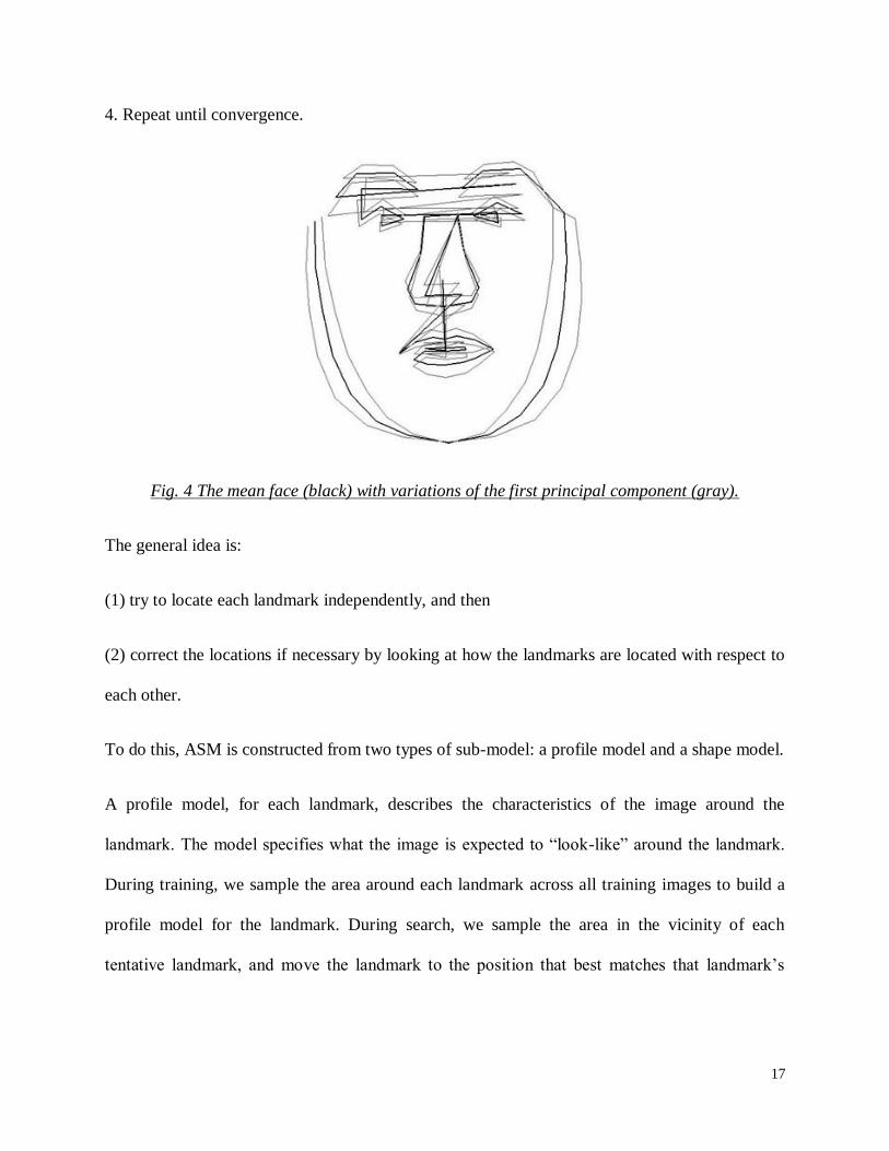
4. Repeat until convergence.
Fig. 4 The mean face (black) with variations of the first principal component (gray).
The general idea is:
(1) try to locate each landmark independently, and then
(2) correct the locations if necessary by looking at how the landmarks are located with respect to
each other.
To do this, ASM is constructed from two types of sub-model: a profile model and a shape model.
A profile model, for each landmark, describes the characteristics of the image around the
landmark. The model specifies what the image is expected to “look-like” around the landmark.
During training, we sample the area around each landmark across all training images to build a
profile model for the landmark. During search, we sample the area in the vicinity of each
tentative landmark, and move the landmark to the position that best matches that landmark’s

18
model profile. This generates tentative new positions for the landmarks, called the suggested
shape.
A shape models defines the allowable relative position of the landmarks. During the search, the
shape model adjusts the shape suggested by the profile model to conform to a legitimate shape.
This is needed because the profile matches at each landmark are unreliable.
To make the search more efficient, more robust, and converges correctly to the correct shape,
ASM can be enhanced with multi-resolution search. Search using multiresolution image is done
by forming a pyramid. Search starts from the smallest image resolution or the highest level first.
If at that level is convergent, then rose to a higher resolution obtained by using the search form
on the previous resolution. This process is done continuously until it reaches the normal
resolution or level 0. Vector model profiles that are used in different resolutions must be
different, but its form must be the same despite different translation and dilation. In general, the
search by using multi-resolution is more robust.

19
CHAPTER III: METHODOLOGY
For creating a facial feature recognition system we need to develop an application which works
in real-time as well with static images with good accuracy as well as good speed. We are
approaching this project using OpenCV (Open Computer Vision) library with a compiler named
CodeBlocks. Our entire work is in C++ language. We have taken help from various project
groups working on facial feature recognition using OpenCV library[8]
.We have compiled all the
codes in Windows platform with a 2.00GHz Intel Core2Duo processor. All the real-time videos
and images are taken from a Logitech C-170 webcam.
Implementing Haar concept-
MAKING A HAAR CLASSIFIER
A Haar Classifier is a machine learning approach for visual object detection. The power of the
Haar Classifier is that it will quickly reject regions that are highly unlikely to contain the object.
It does this by making use of the cascade of classifiers. In this cascade, the early stages will
quickly reject the majority of false regions and the object detection can move on to other regions.
The later stages however require progressively more computational effort in order to reject the
region. By doing this, the Haar Classifier will only spend substantial time on regions that are
likely to contain the object being searched for.
Preparing Image Data-
Positive Images: It is the collection of images that contain only objects of interest, closed eye
Negative Images: It is the collection of images that does not contain objects of interest, to train
Haar cascade classifier.

20
Cropping Image data-
To collect positive images, we have to crop images a lot by our hand which is done by a software
image clipper.
Creating text file-
1. In the Windows command prompt give the directory as cd <full path of the image folder>
2. Write the name of the folder where the images are kept of which you want to generate txt file
>find folder* -name ‘*.png’>positives.dat
folder*: positive images folder
Similarly for creating negatives.dat
>find folder* -name ‘.*jpg’>negatives.dat
folder*: negative images folder
The text file of the negative images is referred to as collection file.
And positive text file is referred to as description file.
3. In the positives.txt take care to remove underscores that is generated and remove .png at the
end.
4. In the positives.txt give the directory of the images as the original image not the clipped ones.
5. In the positives.txt if the value at the object instance is 0, change is to 1 or appropriate number
depending on the number of object instance.
6. Remember to keep every file in the same folder. All .dll files necessary for OpenCV
functioning and the four .exe files like createsamples.exe, haartraining.exe, haarconv.exe and
performance.exe should also be kept in the same folder.

21
CREATING SAMPLES
The first function of the createsamples utility is to create training samples from one image
applying distortions. This function is launched when options, -img, -bg and –vec are
specified.
-img<one_positive_image>
-bg<collection_file_of_negatives>
-vec<name_of_the_output_file_containing_the_generated_samples>
For example:
This generates <num> number of samples from one <positive_image> applying distortions.
Only the first <num> negative images in the <collection_file_of_negatives> are used.
CREATING TRAINING SAMPLES-
The second function is to create training samples from some images without applying
distortions. This function is launched when options, -info, and –vec were specified.
-info<description_file_of_samples>
-vec<name_of_the_output_file_containing_the_generated_samples>
The format of the <description_file_of_samples> is as follows:
[filename] [instance of objects] [[x y width height] [………..2nd
object]……….]
[filename] [instance of objects] [[x y width height] […………2nd
object]………]
where (x,y) is the left-upper corner of the object where the origin (0,0) is the left-upper
corner of the image such as

22
These function crops regions specified and resize these images and convert into .vec
format.
createsamples –info positives.txt –num 1879 –bg.txt –vec sample1.vec –maxxangle 0.5 –
maxyangle 0.5 –maxzangle 0.5 –maxidev 100 –bgcolor 0 –bgthresh 0
where,
No of negative images taken: 1879
Bg.txt: negative text file
Positives.txt: positive text file
Sample1: vector file
CREATING A DESCRIPTION FILE
When already cropped image files are available
For such a situation, you should use the find command and the identify command (cygwin
should have identify (ImageMagick) command) to create a description file as
If all images have the same size, it becomes simpler and faster,

23
CREATING TEST SAMPLES
The third function is to create test samples and their ground truth from single image
applying distortions. This function is triggered when options, -img, -bg, and –info were
specified.
-img<one_positive_image>
-bg<collection_file_of_negatives>
-info<generated_description_file_for_the_generated_test_images>
In this case, -w and –h are used to determine the minimal size of positives to be
embedded in the test images.
Be careful that only the first <num> negative images in the
<collection_file_of_negatives> are used.
This generates tons of jpg files.
The output image filename format is as <number>_<x>_<y>_<width>_<height>.jpg,
where x, y, width and height are the coordinates of placed object bounding rectangle.
Also, this generates <description_file_for_test_samples> of the description file format.
SHOWING IMAGES
The fourth function is to show images within a vec file. This function is triggered when
only an option, -vec, was specified (no –info, -img, -bg).

24
HAAR TRAINING
Now we train our own classifier using the haartraining utility.
The “-nonsym” option is used when the object class does not have vertical (left-right) symmetry.
If object class has vertical symmetry such as frontal faces, “-sym(default)” should be used. It will
speed up processingbecause it will use only the half (the centered and either of the left-sided or
the right-sided) haar-like features.
The “-mode ALL” uses Extended Sets of Haar-like Features.Default is BASIC and it uses only
upright features, while ALL uses the full set of upright and 45 degrees rotated feature set.
The “-mem 512” is the available memory in MB for precalculation. Default is 200MB, so
increase if more memory is available.
haartraining –data cleye –vec sample1.vec –bg bg.txt –nstages 20 –nsplits 2 –minhitrate
0.99 –maxfalsealarm 0.5 –npos 1879 –nneg 501 –w 24 –h 24 –nonsym –mem 512 –mode
ALL
where, cleye = classifier.
GENERATING AN .XML FILE
The haartraining generates a xml file when the process is completely finished.
If you want to convert an intermediate haartraining output dir tree data into a xml file, there is a
software at the OpenCV/samples/c/convert_cascade.c (Installation directory).compile it
The input format is as:
For example:
.

25
Face feature detection using Haar concept-
The following are the functions we used in writing the program for implementing Haar concepts
for facial feature detection. Some are user defined and some are inbuilt. The inbuilt function’s
arguments have been explained below-
1. CvHaarClassifierCascade:- The word cascade here means that the resultant classifier
consists of several simpler classifiers(stages) that are applied subsequently to a region of
interest until at some stage the portion is rejected and it will pass. This is also a structure
that stores the flags, the number of stages, current object size.
2. CvMemStorage:-It is basically a structure used to store the dynamically growing data
structures such as sequences, contours, graphs, subdivisions etc.
3. haarcascade_righteye_2splits.xml:- previously trained file that is being accessed by the
program.It defines the classification criteria used in the detection process.
4. Capture is a pointer of type CvCapture that initiates the camera to be made on.
5. cvNamedWindow:- creates window for showing the outputs as like images or videos.
6. cvQueryFrame( capture )– this command invokes and initiates the frame acquisition.
7. cvSmooth:-This functions smooths an image using cvblur or cv_gaussian and other
methods.
8. cascade1 = ( CvHaarClassifierCascade* )cvLoad( filename, 0, 0, 0 ):-
filename:-name of the directory containing the description of a trained cascade classifier.
9. cvHaarDetectObjects(img,cascade2,storage2,1.1,3,0,CvSize( 40, 40 ) )
img– Image to detect objects in
cascade2 – Haar classifier cascade in internal representation

26
storage2– Memory storage to store the resultant sequence of the object candidate
rectangles
1.1 - The factor by which the search window is scaled between the subsequent
scans, 1.1 means increasing window by 10%
3 - Minimum number (minus 1) of neighbor rectangles that makes up an object.
All the groups of a smaller number of rectangles than min_neighbors-1 are rejected. If
min_neighbors is 0, the function does not any grouping at all and returns all the detected
candidate rectangles, which may be useful if the user wants to apply a customized
grouping procedure
10. cvRectangle :- this functions draws a rectangle in the first argument which is the destined
image and the further arguments explain about its location where rectangle is to be
drawn.
PROPOSING A NEW FACE LANDMARKING CONCEPT-
After studying various face recognition and feature extracting techniques, we are proposing a
new face landmarking concept as we get as a result of ASM or other active contour models. In
our method, we utilize the concept of Haar classifiers, edge detection and contour mapping. Our
algorithm is explained as follows-
1. Finding facial region using Haar concept-
In this step we utilize the Haar concept to crop out the face region from a image in which
the facial landmarking can be done.
27
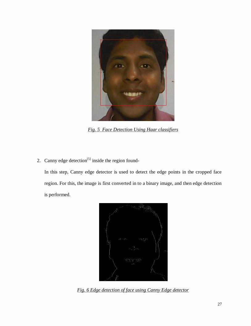
Fig. 5 Face Detection Using Haar classifiers
2. Canny edge detection[5]
inside the region found-
In this step, Canny edge detector is used to detect the edge points in the cropped face
region. For this, the image is first converted in to a binary image, and then edge detection
is performed.
Fig. 6 Edge detection of face using Canny Edge detector

28
3. Finding the contours of facial region-
In this step we find the contour of the binary image, so as to obtain the points on the
facial region with same elevation at edges obtained as above. Now, the contours are
represented on the colored image.
Fig. 7 Contour drawn over the face
4. Representing all the contours with rectangles-
In this step, we draw rectangles for each continuous contour, so that, all the similar
elevated points are covered in a rectangle.
5. Finding the center of the rectangles-
In this step, we calculate the center of the rectangle and represent it by a point circle so as
to represent a landmark point. By this we achieve a large number of points on the face
image.
29
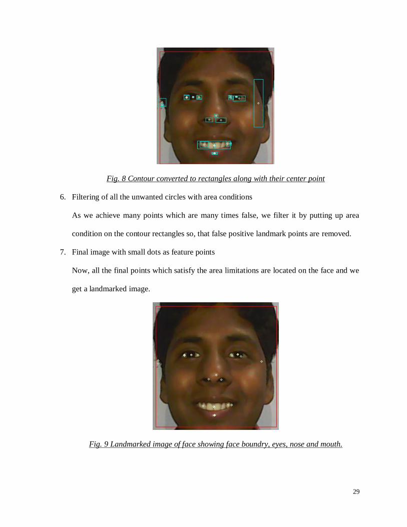
Fig. 8 Contour converted to rectangles along with their center point
6. Filtering of all the unwanted circles with area conditions
As we achieve many points which are many times false, we filter it by putting up area
condition on the contour rectangles so, that false positive landmark points are removed.
7. Final image with small dots as feature points
Now, all the final points which satisfy the area limitations are located on the face and we
get a landmarked image.
Fig. 9 Landmarked image of face showing face boundry, eyes, nose and mouth.

30
8. Calculation of total number of feature points- All the obtained points are counted and
their co-ordinates are stored for further analysis.
9. Segmenting the face using coordinate system (based on some measurements) i.e. relative
distances between two eyes. This will help us know the change in any feature points in
particular face region while dealing with facial gesture recognition.
Constrains related with the proposed algorithm-
1. The lighting condition should be uniform.
2. Camera should be pointing directly to the face.
3. Depending upon the light intensity the Canny parameters and area filter size are to be
generalized.
31
CHAPTER IV: RESULTS
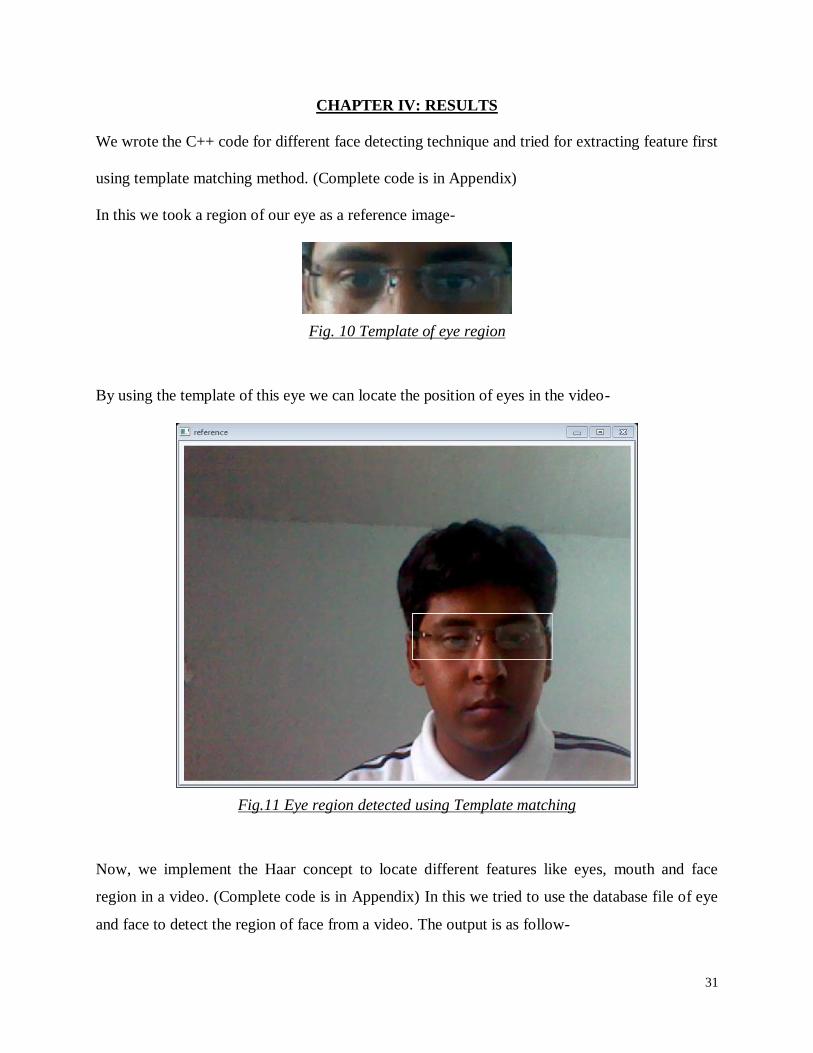
We wrote the C++ code for different face detecting technique and tried for extracting feature first
using template matching method. (Complete code is in Appendix)
In this we took a region of our eye as a reference image-
Fig. 10 Template of eye region
By using the template of this eye we can locate the position of eyes in the video-
Fig.11 Eye region detected using Template matching
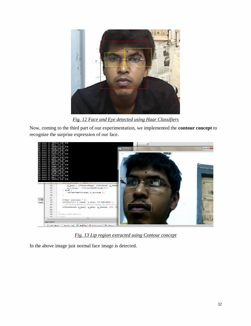
Now, we implement the Haar concept to locate different features like eyes, mouth and face
region in a video. (Complete code is in Appendix) In this we tried to use the database file of eye
and face to detect the region of face from a video. The output is as follow-
32
Fig. 12 Face and Eye detected using Haar Classifiers
Now, coming to the third part of our experimentation, we implemented the contour concept to
recognize the surprise expression of our face.
Fig. 13 Lip region extracted using Contour concept
In the above image just normal face image is detected.
33
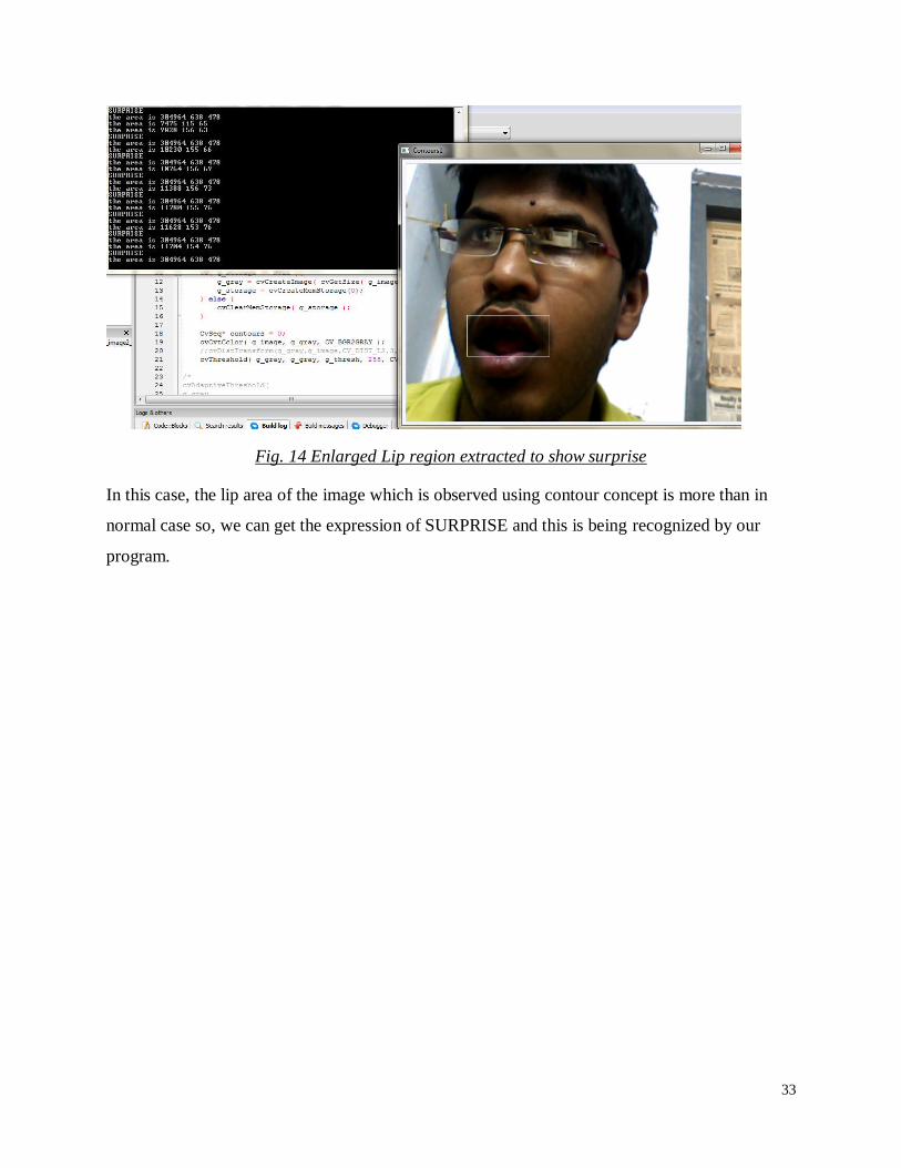
Fig. 14 Enlarged Lip region extracted to show surprise
In this case, the lip area of the image which is observed using contour concept is more than in
normal case so, we can get the expression of SURPRISE and this is being recognized by our
program.

34
CHAPTER V: CONCLUSION
From our project work we conclude that-
i. There are various techniques for facial detection and feature detection. We learned
some of them.
ii. We implemented template matching approach, Haar classifier approach, Contour
approach for face detection and feature extraction.
iii. We studied about the Active Shape models and tried to propose a simpler algorithm
to find the face landmarks on the image by utilizing the concept of Haar classifiers,
Contour mapping and edge detection.
iv. Though algorithm proposed by us is not so much robust and contain lots of
constrains, future works in it may make it more robust and reliable and applicable for
any type of facial image.

35
REFERENCES
1. Ming-Hsuan Yang, David J. Kriegman, and Narendra Ahuja, “Detecting Faces in
Images: A Survey”, IEEE TRANSACTIONS ON PATTERN ANALYSIS AND
MACHINE INTELLIGENCE, VOL. 24, NO. 1, JANUARY 2002.
2. Takeshi Mita, Toshimitsu Kaneko and Osamu Hori, “JOINT HAAR-LIKE
FEATURES FOR FACE DETECTION”, Multimedia Laboratory, Corporate
Research & Development Center, Toshiba Corporation, Proceedings of the Tenth
IEEE International Conference on Computer Vision (ICCV’05).
3. Perlibakas, V., Contours and ellipses-based face detection. International Conference
on Informatics for Health Care, P62–67, 2002.
4. Paul Viola and Michael Jones, “Robust Real-time Object Detection”. Second
International Workshop On Statistical And Computational Theories Of Vision –
Modeling, Learning, Computing, And Sampling, 2001.
5. Canny, J., A Computational Approach To Edge Detection, IEEE Trans. Pattern
Analysis and Machine Intelligence, 8(6):679–698, 1986.
6. Cootes, T.F., C.J. Taylor, D.H. Cooper, & J. Graham. Active Shape Models---Their
Training and Application. Computer Vision and Image Understanding, Vol.61, No.1,
January, pp. 38-59, 1995.
7. Milborrow, Stephen. Locating Facial Features with Active Shape Models. Cape Town
University, Australia, 2007.
8. http://opencv.willowgarage.com/wiki/

36
APPENDIX
The C++ Code for Template matching method-
1 #include <cxcore.h> 2 #include <stdio.h> 3 #include <cv.h> 4 #include <highgui.h> 5 IplImage *grey = NULL; 6 IplImage *edges = NULL; 7 IplImage* DrawHistogram(CvHistogram *hist, float scaleX=1, float scaleY=1)
8 { float histMax = 0;
9 cvGetMinMaxHistValue(hist, 0, &histMax, 0, 0); 10 IplImage* imgHist = cvCreateImage(cvSize(256*scaleX, 64*scaleY), 8 ,1); 11 cvZero(imgHist); 12 for(int i=0;i<255;i++)
13 { 14 float histValue = cvQueryHistValue_1D(hist, i);
15 float nextValue = cvQueryHistValue_1D(hist, i+1);
16 CvPoint pt1 = cvPoint(i*scaleX, 64*scaleY); 17 CvPoint pt2 = cvPoint(i*scaleX+scaleX, 64*scaleY); 18 CvPoint pt3 = cvPoint(i*scaleX+scaleX, (64-nextValue*64/histMax)*scaleY); 19 CvPoint pt4 = cvPoint(i*scaleX, (64-histValue*64/histMax)*scaleY);
20 int numPts = 5;
21 CvPoint pts[] = {pt1, pt2, pt3, pt4, pt1}; 22 printf("points are %d %d \n",pt1); 23 printf("points are %d %d \n",pt2); 24 printf("points are %d %d \n",pt3); 25 printf("points are %d %d \n",pt4); 26 cvFillConvexPoly(imgHist, pts, numPts, cvScalar(255)); 27 } 28 return imgHist;
29 } 30 int main( int argc, char** argv )
31 { 32 IplImage *img; 33 IplImage *tpl; 34 IplImage *res; 35 CvPoint minloc, maxloc; 36 double minval, maxval;
37 int img_width, img_height;
38 int tpl_width, tpl_height;
39 int res_width, res_height;
40 CvCapture* capture = cvCaptureFromCAM( 0 ); 41 for(;;){
42 img = cvQueryFrame( capture ); 43 if( !img )
44 { 45 fprintf( stderr, "ERROR: frame is null...\n" ); 46 getchar(); 47 break;
48 } 49 tpl = cvLoadImage( "eyes.jpg", CV_LOAD_IMAGE_COLOR ); 50 if( tpl == 0 ) {
51 fprintf( stderr, "Cannot load file %s!\n", argv[2] ); 52 return 1;
53 } 54 img_width = img->width; 55 img_height = img->height; 56 tpl_width = tpl->width; 57 tpl_height = tpl->height; 58 res_width = img_width - tpl_width + 1; 59 res_height = img_height - tpl_height + 1; 60 res = cvCreateImage( cvSize( res_width, res_height ), IPL_DEPTH_32F, 1 ); 61 cvMatchTemplate( img, tpl, res, CV_TM_SQDIFF_NORMED ); 62 cvMinMaxLoc( res, &minval, &maxval, &minloc, &maxloc, 0 ); 63 cvRectangle( img, 64 cvPoint( minloc.x, minloc.y ), 65 cvPoint( minloc.x + tpl_width, minloc.y + tpl_height ),

37
66 cvScalar( 255, 255, 255, 0 ), 1, 0, 0 ); 67 CvRect rect = cvRect( minloc.x, minloc.y,minloc.x + tpl_width, minloc.y + tpl_height); 68 IplImage* imgRed = cvCreateImage(cvGetSize(img), 8, 1); 69 IplImage* imgGreen = cvCreateImage(cvGetSize(img), 8, 1); 70 IplImage* imgBlue = cvCreateImage(cvGetSize(img), 8, 1); 71 cvSplit(img,imgBlue, imgGreen, imgRed, NULL); 72 int numBins = 256;
73 float range[] = {0, 255};
74 float *ranges[] = { range };
75 CvHistogram *hist = cvCreateHist(1, &numBins, CV_HIST_ARRAY, ranges, 1); 76 cvClearHist(hist); 77 cvCalcHist(&imgRed, hist, 0, 0); 78 IplImage* imgHistRed = DrawHistogram(hist); 79 cvClearHist(hist); 80 cvCalcHist(&imgGreen, hist, 0, 0); 81 IplImage* imgHistGreen = DrawHistogram(hist); 82 cvClearHist(hist); 83 cvCalcHist(&imgBlue, hist, 0, 0); 84 IplImage* imgHistBlue = DrawHistogram(hist); 85 cvClearHist(hist); 86 grey = cvCreateImage(cvGetSize(img), IPL_DEPTH_8U, 1); 87 edges = cvCreateImage(cvGetSize(img), IPL_DEPTH_8U, 1); 88 cvCvtColor(img, grey, CV_BGR2GRAY); 89 cvCanny( grey, edges, 130,150, 3); 90 cvNamedWindow("edge_detection", CV_WINDOW_AUTOSIZE); 91 cvShowImage("edge_detection", edges); 92 cvResetImageROI( img ); 93 cvNamedWindow( "reference", CV_WINDOW_AUTOSIZE ); 94 cvNamedWindow( "template", CV_WINDOW_AUTOSIZE ); 95 cvShowImage( "reference", img ); 96 cvShowImage( "template", res ); 97 cvNamedWindow("Red"); 98 cvNamedWindow("Green"); 99 cvNamedWindow("Blue"); 100 cvShowImage("Red", imgHistRed); 101 cvShowImage("Green", imgHistGreen); 102 cvShowImage("Blue", imgHistBlue); 103 if( (cvWaitKey(10) & 255) == 27 ) break;
104 } 105 cvDestroyWindow( "reference" ); 106 cvDestroyWindow( "template" ); 107 cvReleaseImage( &img ); 108 cvReleaseImage( &tpl ); 109 cvReleaseImage( &res ); 110 return 0;
111 }
The C++ code for Haar based detection is- 1 #include <stdio.h> 2 #include "cv.h" 3 #include "highgui.h" 4 CvHaarClassifierCascade *cascade1; 5 CvHaarClassifierCascade *cascade2; 6 CvMemStorage *storage1; 7 CvMemStorage *storage2; 8 void detectFaces( IplImage *img );
9 int main( int argc, char** argv )
10 { 11 CvCapture *capture; 12 IplImage *frame; 13 IplImage *frame2; 14 int key;
15 char *filename = "haarcascade_frontalface_alt2.xml";
16 char *filename2 = "haarcascade_mcs_lefteye.xml";
17 cascade1 = ( CvHaarClassifierCascade* )cvLoad( filename, 0, 0, 0 ); 18 cascade2 = ( CvHaarClassifierCascade* )cvLoad( filename2, 0, 0, 0 ); 19 storage1 = cvCreateMemStorage( 0 ); 20 storage2 = cvCreateMemStorage( 0 );

38
21 capture = cvCaptureFromCAM( 0 ); 22 cvNamedWindow( "video", 1 ); 23 while( key != 'q' ) {
24 frame = cvQueryFrame( capture ); 25 cvSmooth(frame,frame); 26 if( !frame ) {
27 fprintf( stderr, "Cannot query frame!\n" ); 28 break;
29 } 30 frame->origin = 0; 31 detectFaces( frame ); 32 key = cvWaitKey(10); 33 } 34 cvReleaseCapture( &capture ); 35 cvDestroyWindow( "video" ); 36 cvReleaseHaarClassifierCascade( &cascade1 ); 37 cvReleaseMemStorage( &storage1 ); 38 cvReleaseMemStorage( &storage2 ); 39 return 0;
40 } 41 void detectFaces( IplImage *img )
42 { 43 int i,j;
44 CvSeq *faces = cvHaarDetectObjects( 45 img, 46 cascade1, 47 storage1, 48 1.1, 49 3, 50 0, 51 cvSize( 40, 40 ) ); 52 CvSeq *faces2 = cvHaarDetectObjects( 53 img, 54 cascade2, 55 storage2, 56 1.1, 57 3, 58 0, 59 cvSize( 40, 40 ) ); 60 for( i = 0 ,j=0; i < ( faces->total ) ; i++ )
61 { 62 CvRect *r = ( CvRect* )cvGetSeqElem( faces, i ); 63 cvRectangle( img, 64 cvPoint( r->x, r->y ), 65 cvPoint( r->x + r->width, r->y + r->height ), 66 CV_RGB( 211, 0, 0 ), 1, 8, 0 ); 67 printf("points r.x %d ",r->x); 68 printf("points r.y %d \n",r->y); 69 CvPoint p1,p2; 70 p2.x=r->x+((r->width)/2); 71 p2.y=r->y+((r->height)/2); 72 } 73 for( j=0; j < ( faces2->total ) ; j++ )
74 { 75 CvRect *r1 = ( CvRect* )cvGetSeqElem( faces2, j ); 76 cvRectangle( img, 77 cvPoint( r1->x, r1->y ), 78 cvPoint( r1->x + r1->width, r1->y + r1->height ), 79 CV_RGB( 211, 211, 0 ), 1, 8, 0 ); 80 } 81 cvShowImage( "video", img ); 82 }
The C++ code for facial gesture recognition using contour concept is- 1 #include <stdio.h> 2 #include <cv.h> 3 #include <highgui.h> 4 #include <conio.h>

39
5 IplImage* g_image = NULL; 6 IplImage* g_gray = NULL; 7 int g_thresh = 21;
8 CvMemStorage* g_storage = NULL; 9 CvSeq* contourLow; 10 void on_trackbar(int){
11 if( g_storage == NULL ){
12 g_gray = cvCreateImage( cvGetSize( g_image ), 8, 1 ); 13 g_storage = cvCreateMemStorage(0); 14 } else {
15 cvClearMemStorage( g_storage ); 16 } 17 CvSeq* contours = 0; 18 cvCvtColor( g_image, g_gray, CV_BGR2GRAY ); 19 cvThreshold( g_gray, g_gray, g_thresh, 255, CV_THRESH_BINARY ); 20 cvFindContours( g_gray, g_storage, &contours ); 21 CvPoint pt1, pt2; 22 contourLow=cvApproxPoly(contours, sizeof(CvContour),g_storage,CV_POLY_APPROX_DP,3,6);
23 for( ; contourLow != 0; contourLow = contourLow->h_next )
24 { CvRect rect; 25 CvScalar color = CV_RGB(200,200,200 ); 26 rect=cvBoundingRect(contourLow, NULL); 27 pt1.x = rect.x; 28 pt2.x = (rect.x+rect.width); 29 pt1.y = rect.y; 30 pt2.y = (rect.y+rect.height); 31 if((rect.width*rect.height)>7000)
32 {cvRectangle(g_image, pt1,pt2, color, 1, 8, 0); 33 int x=rect.width*rect.height;
34 printf("the area is %d %d %d \n",x,rect.width,rect.height); 35 if(x>9000 && x<14000)
36 {printf("SURPRISE \n");} 37 } 38 } 39 cvShowImage( "Contours", g_gray ); 40 cvShowImage( "Contours1", g_image ); 41 } 42 int main(int argc, _TCHAR* argv[])
43 { CvCapture* capture = cvCreateCameraCapture(0); 44 IplImage* frame = cvQueryFrame(capture ); 45 char key =0;
46 cvNamedWindow( "Contours", 1 ); 47 cvNamedWindow( "Contours1", 1 ); 48 while (key !='q')
49 { 50 g_image = cvQueryFrame(capture); 51 cvSmooth(g_image,g_image,CV_GAUSSIAN,3,0,0,0); 52 cvCreateTrackbar( "Threshold", "Contours", &g_thresh, 255, on_trackbar ); 53 on_trackbar(0); 54 cvWaitKey(11);} 55 return 0;
56 }
The C++ code for the proposed facial landmarking method-
1 #include <cv.h> 2 #include <highgui.h> 3 CvSeq* contourLow; 4 IplImage* out1; 5 IplImage* out; 6 IplImage* frame; 7 CvHaarClassifierCascade *cascade; //cascade for detecting faces 8 CvMemStorage *storage; //temporary storage of memory 9 void detectFaces( IplImage *img ); // function for detecting faces 10 int main(int argc, char *argv[]) 11 { 12 char *filename = "haarcascade_frontalface_alt.xml"; 13 cascade = ( CvHaarClassifierCascade* )cvLoad( filename, 0, 0, 0 );

40
14 storage = cvCreateMemStorage( 0 ); 15 cvNamedWindow( "video", 1 ); 16 frame = cvLoadImage( "C:/a1 - Copy.jpg", 1); 17 IplImage* frame2; 18 frame2=frame; 19 cvNamedWindow( "example-input" ); 20 cvNamedWindow( "example-output" ); 21 cvNamedWindow( "example-output1" ); 22 out1 = cvCreateImage( cvSize(frame->width,frame->height),frame->depth,1); 23 out = cvCreateImage( cvSize(frame->width,frame->height),frame->depth,frame->nChannels ); 24 cvCvtColor(frame,out1, CV_RGB2GRAY); 25 CvSeq* contours = 0; 26 CvMemStorage* g_storage = NULL; 27 g_storage = cvCreateMemStorage(0); 28 cvCanny( out1, out1, 70,140,3 ); // canny edge detection finding edges 29 cvFindContours( out1, g_storage, &contours ); 30 31 if( contours ){ // draw the contours 32 cvDrawContours( 33 frame2, 34 contours, 35 cvScalarAll(255), 36 cvScalarAll(255), 37 100 ); 38 } 39 CvPoint pt1, pt2,pt3; //plotting the points 40 contourLow=cvApproxPoly(contours, sizeof(CvContour),g_storage,CV_POLY_APPROX_DP,3,6); 41 int i=0; 42 for( ; contourLow != 0; contourLow = contourLow->h_next ) 43 { 44 CvRect rect; 45 CvScalar color = CV_RGB(0,200,200 ); 46 rect=cvBoundingRect(contourLow, NULL); 47 pt1.x = rect.x; 48 pt2.x = (rect.x+rect.width); 49 pt3.x = (rect.x+0.5*rect.width); 50 int a=pt3.x; 51 pt1.y = rect.y; 52 pt2.y = (rect.y+rect.height); 53 pt3.y = (rect.y+0.5*rect.height); 54 int b=pt3.y; 55 if((rect.width*rect.height)>40 && (rect.width*rect.height)<2000) 56 {cvRectangle(frame, pt1,pt2, color, 1, 8, 0); //draw the rectangles involving the contours 57 cvCircle(frame, /* the dest image */ 58 cvPoint(pt3.x,pt3.y), 2, /* center point and radius */ 59 cvScalar(255,255 ,255, 1), /* the color; red */ 60 0, 8, 0); 61 cvLine(frame, 62 cvPoint(a,b), 63 cvPoint(pt3.x,pt3.y), 64 cvScalar(0, 255, 0, 0), 65 1, 8, 0); 66 i++; } 67 } 68 printf("the number of countour ponits after filtering %d \n",i); //prints the contour points after filtering 69 cvSetImageROI(frame, cvRect(1,1,1,1)); 70 IplImage *img2 = cvCreateImage(cvGetSize(frame), 71 frame->depth, 72 frame->nChannels); 73 cvCopy(frame, img2, NULL); 74 cvResetImageROI(frame); 75 cvShowImage("example-input", frame2); 76 cvShowImage("example-output", out1); 77 cvShowImage("example-output2", frame); 78 cvWaitKey(0); 79 cvReleaseImage( &frame ); 80 cvReleaseImage( &out1 );

41
81 cvDestroyWindow( "example-input" ); 82 cvDestroyWindow( "example-output" ); 83 return 0; 84 } 85 void detectFaces( IplImage *img ) 86 { 87 int i; 88 /* detect faces */ 89 CvSeq *faces = cvHaarDetectObjects( 90 img, 91 cascade, 92 storage, 93 1.1, 94 3, 95 0 /*CV_HAAR_DO_CANNY_PRUNNING*/, 96 cvSize( 40, 40 ) ); 97 /* for each face found, draw a red box */ 98 for( i = 0 ; i < ( faces ? faces->total : 0 ) ; i++ ) { 99 CvRect *r = ( CvRect* )cvGetSeqElem( faces, i ); 100 cvRectangle( img, 101 cvPoint( r->x, r->y ), 102 cvPoint( r->x + r->width, r->y + r->height ), 103 CV_RGB( 255, 0, 0 ), 1, 8, 0 ); 104 } 105 /* display video */ 106 cvShowImage( "video", img ); 107 }