Embed Size (px)
Citation preview
International Journal of Power Electronics and Drive System (IJPEDS)Vol. 7, No. 2, June 2016, pp. 387~396ISSN: 2088-8694 387
Journal homepage: http://iaesjournal.com/online/index.php/IJPEDS
Design of Hollow-Rotor Brushless DC Motor
Raja Nor Firdaus Raja Othman1, 2, Farina Sulaiman 1, 2, Suhairi Rizuan1, 2, 3, Kasrul Abdul Karim1, 2 ,Auzani Jidin1,2, Tole Sutikno4, Norhisam Misron5
1Faculty of Electrical Engineering, Universiti Teknikal Malaysia, Melaka, Malaysia2Electrical Machine Design, Power Electronics and Drives Research Group, CeRIA, UTeM
3Electrical Technology Section, Universiti Kuala Lumpur-British Malaysian Institute, Malaysia4Department of Electrical Engineering, Universitas Ahmad Dahlan, Yogyakarta, Indonesia
5Faculty of Engineering, Universiti Putra Malaysia, 43400 Serdang, Selangor, Malaysia
Article Info ABSTRACT
Article history:
Received Feb 6, 2015Revised Apr 22, 2015Accepted May 4, 2016
This paper discusses about design of hollow-rotor Brushless DC (BLDC)motor. A conventional BLDC motor has more leakage flux circling at the endof the permanent magnet that will limit torque. To overcome this problem, anew BLDC model known as hollow-rotor is proposed. The objective of thisresearch is to design a hollow-rotor motor that will have higher torquedensity compared to conventional BLDC motor using Finite Element Method(FEM). In addition, performance analysis of the proposed hollow-rotor hasalso been carried out. For validation, the result of FEM is compared with themeasurement result. It shows that, the simulation result has good agreementwith the measurement result. For comparison, hollow-rotor shows highertorque density compared to conventional BLDC motor. As a conclusion, thispaper provides guidelines and analysis in designing high torque hollow-rotormotor.
Keyword:
BLDC motorFinite element methodHollow-rotorLeakage flux circling
Copyright © 2016 Institute of Advanced Engineering and Science.All rights reserved.
Corresponding Author:
Raja Nor Firdaus Raja Othman,Faculty of Electrical Engineering, Universiti Teknikal Malaysia, Melaka, MalaysiaHang Tuah Jaya, 76100 Durian Tunggal, Melaka, Malaysia.Email: [email protected]
1. INTRODUCTIONBLDC motor is widely used in many applications, especially for home appliances such as blender,
fan, mixer and vacuum [1-2]. The rotor of a typical BLDC motor usually has permanent magnets. By usingpermanent magnet, no electrical energy is required to excite the field, thus increasing the efficiency, torquedensity and power density of the motor [3-4]. Many researchers had focused on improving the torque ofBLDC motor. For instance, Gyu-Hong Kang et al. studied irreversible demagnetization of permanentmagnet. This irreversible demagnetization characteristic is analyzed by rotor structure. In a BLDC motor, thereluctance torque strongly influences the torque characteristics. By considering these characteristics, themotor performance in terms of magnetic flux density will proportionally increase the torque [5-7]. Anotherexample is the study by Byoung-Kuk Lee et al., who presented a detailed comparative study of BLDC motordue to operating condition. In this study, flux barriers are design in order to improve torque characteristics.By using this method, magnetic flux will be concentrated in the air gap. As a result, flux barrier canmaximize the torque of the BLDC motor compared to conventional types [8-10]. M.R. Mizanoor et al.presented an analytical model for calculating the back emf and the maximum value of air gap flux density inboth radial and tangential directions for internal rotor topology. The flux density in the air gap region isderived by considering the stator slot opening [11-12]. Another researcher, K.W. Hyung et al proposed amethod for optimizing torque for developing the neodymium free spoke type BLDC motor. An importantstep during motor design is the calculation of the effective air gap flux density. Effective air gap flux densityis contributed from the flux of magnet [13]. In summary, most of the researchers increase torque by applying
ISSN: 2088-8694
IJPEDS Vol. 7, No. 2, June 2016 : 387– 396
388
a barrier or decrease the losses of the demagnetization effect. However, it will be better if a new methodcould be introduced to solve both problems. For such reason, magnetic flux below the permanent magnet isessential to minimize the leakage flux. The leakage flux does not contribute to the torque generation.
This paper presents design of hollow-rotor BLDC motor. Several design parameters for designingthe conventional BLDC motor had been investigated. A new model known hollow-rotor is design to improvethe performance for BLDC motor. Hollow-rotor motor is fabricated and the measurement result is comparedwith FEM. The result shows that simulation has shown good agreement with measurement result. Theproposed hollow-rotor motor can be designed for higher rating of BLDC motor up to kW specification.
2. DESIGN OF CONVENTIONAL BLDC2.1. Design of Stator and Coil
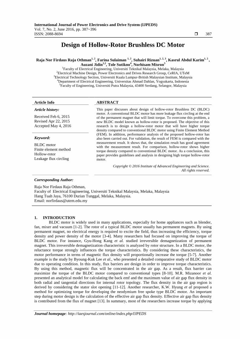
Before designing hollow-rotor, a conventional BLDC motor is design first. The stator and rotordesign for conventional BLDC motor is shown in Figure 1. In this research, BLDC motor is design for 9 slot8 pole arrangements. Investigation is made in order to properly design of stator and magnet volume withreasonable design parameter so that motor performance can be maximized. The rotor and stator is mostlycovered by standard silicon steel grade as J1: 50H800. Futher details about design parameter are shown intable 1. At this stage, no permanent magnet is applied to the motor.
stw
r1
r2
r3
cwc
h
Figure 1. Stator and rotor design
The fixed parameter for designing BLDC motor is the stator radius r1, inner rotor radius r2, outerrotor radius r3, coil height ch, coil width cw, air gap ag, distance slot opening d1. The varied parameter is thestator tooth height sth which is change from 1 mm to 2 mm. Stator tooth width stw is change from 2 mm to 4mm. Stator tooth width stw is change linearly with the change of sth from 1 mm to 2 mm with the differenceof 0.5 mm as shown in equation (1).
)(21
wtht ss (1)
Number of turn, n is set from 26 until 10 accordingly to the coil size, cs of coil slot space. The coil turn canbe calculated by;
%70
s
h
s
w
c
c
c
cN (2)
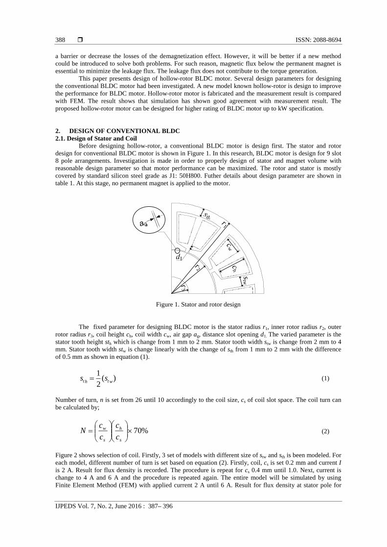
Figure 2 shows selection of coil. Firstly, 3 set of models with different size of stw and sth is been modeled. Foreach model, different number of turn is set based on equation (2). Firstly, coil, cs is set 0.2 mm and current Iis 2 A. Result for flux density is recorded. The procedure is repeat for cs 0.4 mm until 1.0. Next, current ischange to 4 A and 6 A and the procedure is repeated again. The entire model will be simulated by usingFinite Element Method (FEM) with applied current 2 A until 6 A. Result for flux density at stator pole for
IJPEDS ISSN: 2088-8694
Design of Hollow-Rotor Brushless DC Motor (Raja Nor Firdaus Raja Othman)
389
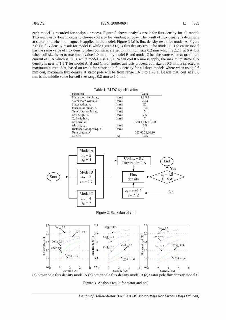
each model is recorded for analysis process. Figure 3 shows analysis result for flux density for all model.This analysis is done in order to choose coil size for winding purpose. The result of flux density is determineat stator pole when no magnet is applied in the model. Figure 3 (a) is flux density result for model A. Figure3 (b) is flux density result for model B while figure 3 (c) is flux density result for model C. The entire modelhas the same value of flux density when coil sizes are set to minimum size 0.2 mm which is 2.2 T at 6 A, butwhen coil size is set to maximum value 1.0 mm, only model B and model C has the same value at maximumcurrent of 6 A which is 0.8 T while model A is 1.3 T. When coil 0.6 mm is apply, the maximum stator fluxdensity is near to 1.5 T for model A, B and C. For further analysis process, coil size of 0.6 mm is selected atmaximum current 6 A, based on result for stator pole flux density for all three models where when using 0.6mm coil, maximum flux density at stator pole will be from range 1.6 T to 1.75 T. Beside that, coil size 0.6mm is the middle value for coil size range 0.2 mm to 1.0 mm.
Table 1. BLDC specificationParameter ValueStator tooth height, sth [mm] 1,1.5,2Stator tooth width, stw [mm] 2,3,4Stator radius, r1 [mm] 25Inner rotor radius, r2 [mm] 12.4Outer rotor radius, r3 [mm] 3Coil height, ch [mm] 2.5Coil width, cw [mm] 7Coil size, cs 0.2,0.4,0.6,0.8,1.0Air gap, ag [mm] 0.5Distance slot opening, d1 [mm] 1Num of turn, N 262,65,29,16,10Current [A] 2,4,6
Figure 2. Selection of coil
(a) Stator pole flux density model A (b) Stator pole flux density model B (c) Stator pole flux density model C
Figure 3. Analysis result for stator and coil
ISSN: 2088-8694
IJPEDS Vol. 7, No. 2, June 2016 : 387– 396
390
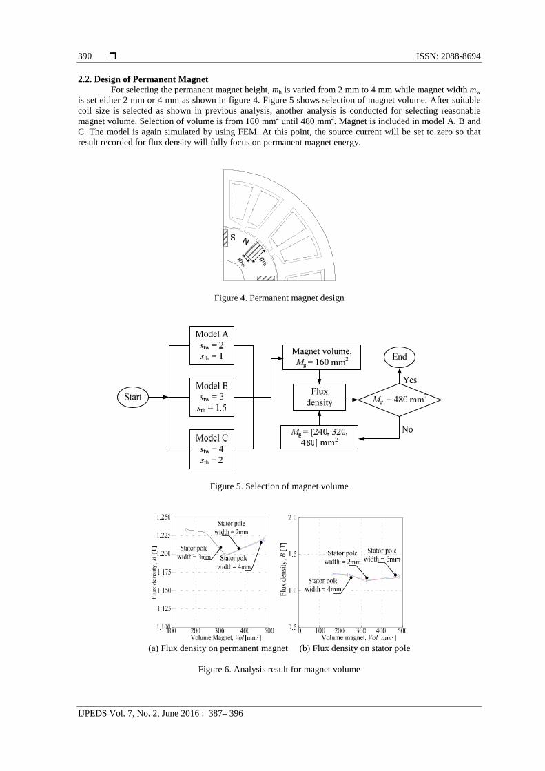
2.2. Design of Permanent MagnetFor selecting the permanent magnet height, mh is varied from 2 mm to 4 mm while magnet width mw
is set either 2 mm or 4 mm as shown in figure 4. Figure 5 shows selection of magnet volume. After suitablecoil size is selected as shown in previous analysis, another analysis is conducted for selecting reasonablemagnet volume. Selection of volume is from 160 mm2 until 480 mm2. Magnet is included in model A, B andC. The model is again simulated by using FEM. At this point, the source current will be set to zero so thatresult recorded for flux density will fully focus on permanent magnet energy.
Figure 4. Permanent magnet design
Figure 5. Selection of magnet volume
(a) Flux density on permanent magnet (b) Flux density on stator pole
Figure 6. Analysis result for magnet volume
IJPEDS ISSN: 2088-8694
Design of Hollow-Rotor Brushless DC Motor (Raja Nor Firdaus Raja Othman)
391
Figure 6 (a) shows magnet flux density for each model when different volume of magnet is inserted in rotor.The result is recorded when there is no current source. The flux density appears is due to permanent magnetenergy. Maximum magnet flux density occurs when magnet volume is 160 mm2 which is 1.23 T whileminimum flux density occurs at magnet volume 320 mm2 which is 1.2 T. All three models have the similarityincreament and decrement point for all magnet volume. Figure 6 (b) shows result for stator pole flux densitywhen magnet is included. During this process, there is current source included which is 6 A and number ofturn N is 29. N is calculated according to equation (2) with the cs selected is 0.6. Maximum flux density is1.229 T for permanent magnet volume 160 mm2 while minimum flux density is 1.14 T for permanent magnetvolume is 320 mm2. The entire model has the same point of flux density for the same permanent magnetvolume.
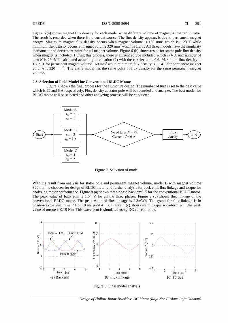
2.3. Selection of Field Model for Conventional BLDC MotorFigure 7 shows the final process for the sturucture design. The number of turn is set to the best value
which is 29 and 6 A respectively. Flux density at stator pole will be recorded and analyze. The best model forBLDC motor will be selected and other analyzing process will be conducted.
Figure 7. Selection of model
With the result from analysis for stator pole and permanent magnet volume, model B with magnet volume320 mm2 is choosen for design of BLDC motor and further analysis for back emf, flux linkage and torque foranalyzing motor performance. Figure 8 (a) shows three-phase back emf, E for the conventional BLDC motor.The peak value of back emf is 1.04 V for all the three phases. Figure 8 (b) shows flux linkage of theconventional BLDC motor. The peak value of flux linkage is 2.3mWb. The graph for flux linkage is inpositive cycle with time, t from 0 ms until 4 ms. Figure 8 (c) shows static torque waveform with the peakvalue of torque is 0.19 Nm. This waveform is simulated using DC current mode.
(a) Backemf (b) Flux linkage (c) Torque
Figure 8. Final model analysis
ISSN: 2088-8694
IJPEDS Vol. 7, No. 2, June 2016 : 387– 396
392
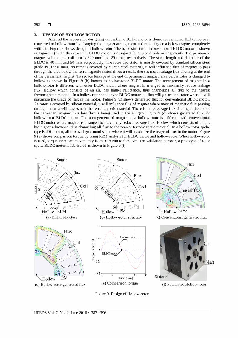
3. DESIGN OF HOLLOW-ROTORAfter all the process for designing canventional BLDC motor is done, conventional BLDC motor is
converted to hollow rotor by changing the magnet arrangement and replacing area below magnet completelywilth air. Figure 9 shows design of hollow-rotor. The basic structure of conventional BLDC motor is shownin Figure 9 (a). In this research, BLDC motor is designed for 9 slot 8 pole arrangements. The permanentmagnet volume and coil turn is 320 mm3 and 29 turns, respectively. The stack length and diameter of theBLDC is 40 mm and 50 mm, respectively. The rotor and stator is mostly covered by standard silicon steelgrade as J1: 50H800. As rotor is covered by silicon steel material, it will influence flux of magnet to passthrough the area below the ferromagnetic material. As a result, there is more leakage flux circling at the endof the permanent magnet. To reduce leakage at the end of permanent magnet, area below rotor is changed tohollow as shown in Figure 9 (b) known as hollow-rotor BLDC motor. The arrangement of magnet in ahollow-rotor is different with other BLDC motor where magnet is arranged to maximally reduce leakageflux. Hollow which consists of an air, has higher reluctance, thus channeling all flux to the nearestferromagnetic material. In a hollow rotor spoke type BLDC motor, all flux will go around stator where it willmaximize the usage of flux in the motor. Figure 9 (c) shows generated flux for conventional BLDC motor.As rotor is covered by silicon material, it will influence flux of magnet where most of magnetic flux passingthrough the area will passes near the ferromagnetic material. There is more leakage flux circling at the end ofthe permanent magnet thus less flux is being used in the air gap. Figure 9 (d) shows generated flux forhollow-rotor BLDC motor. The arrangement of magnet in a hollow-rotor is different with conventionalBLDC motor where magnet is arranged to maximally reduce leakage flux. Hollow which consists of an air,has higher reluctance, thus channeling all flux to the nearest ferromagnetic material. In a hollow rotor spoketype BLDC motor, all flux will go around stator where it will maximize the usage of flux in the motor. Figure9 (e) shows comparison torque by using FEM analysis for BLDC motor and hollow-rotor. When hollow-rotoris used, torque increases maximumly from 0.19 Nm to 0.39 Nm. For validation purpose, a prototype of rotorspoke BLDC motor is fabricated as shown in Figure 9 (f).
(a) BLDC structure (b) Hollow-rotor structure (c) Conventional generated flux
(d) Hollow-rotor generated flux (e) Comparison torque (f) Fabricated Hollow-rotor
Figure 9. Design of Hollow-rotor
IJPEDS ISSN: 2088-8694
Design of Hollow-Rotor Brushless DC Motor (Raja Nor Firdaus Raja Othman)
393
4. EXPERIMENTAL SETUPTo verify simulation result the static and dynamic torque measurement is carried out for the
fabricated model. The static torque of the measurement result is compared with the simulation result.Meanwhile, the dynamic torque (torque and speed characteristic) of the measurement result also conducted.This experiment is to indicate maximum speed and torque when motor are operates.
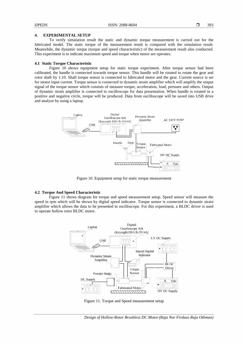
4.1 Static Torque CharacteristicFigure 10 shows equipment setup for static torque experiment. After torque sensor had been
calibrated, the handle is connected towards torque sensor. This handle will be rotated to rotate the gear androtor shaft by 1:10. Shaft torque sensor is connected to fabricated motor and the gear. Current source is setfor motor input current. Torque sensor is connected to dynamic strain amplifier which will amplify the outputsignal of the torque sensor which consists of measure torque, acceleration, load, pressure and others. Outputof dynamic strain amplifier is connected to oscilloscope for data presentation. When handle is rotated in apositive and negative circle, torque will be produced. Data from oscilloscope will be saved into USB driveand analyze by using a laptop.
Figure 10. Equipment setup for static torque measurement
4.2 Torque And Speed CharacteristicFigure 11 shows diagram for torque and speed measurement setup. Speed sensor will measure the
speed in rpm which will be shown by digital speed indicator. Torque sensor is connected to dynamic strainamplifier which allows the data to be presented in oscilloscope. For this experiment, a BLDC driver is usedto operate hollow rotor BLDC motor.
Figure 11. Torque and Speed measurement setup
ISSN: 2088-8694
IJPEDS Vol. 7, No. 2, June 2016 : 387– 396
394
Voltage 15 V is being supply to the BLDC driver to trigging the switching device (MOSFET). Voltage 5 V isset for supplying Hall Effect sensor, meanwhile the motor supply is set for 12 V. Then, for next experimentthe supply is change to 24 V and 48 V. Three phase wye connection is set to BLDC driver. Powder brake isconnected to torque sensor shaft. Other power supply is used for powder brake; the powder brake is beingsupply with 0.5 V, 1.0 V, 1.5 V and 2.0 V to provide different value of braking torque. Figure 11 showsmeasurement setup of torque and speed characteristic in the laboratory.
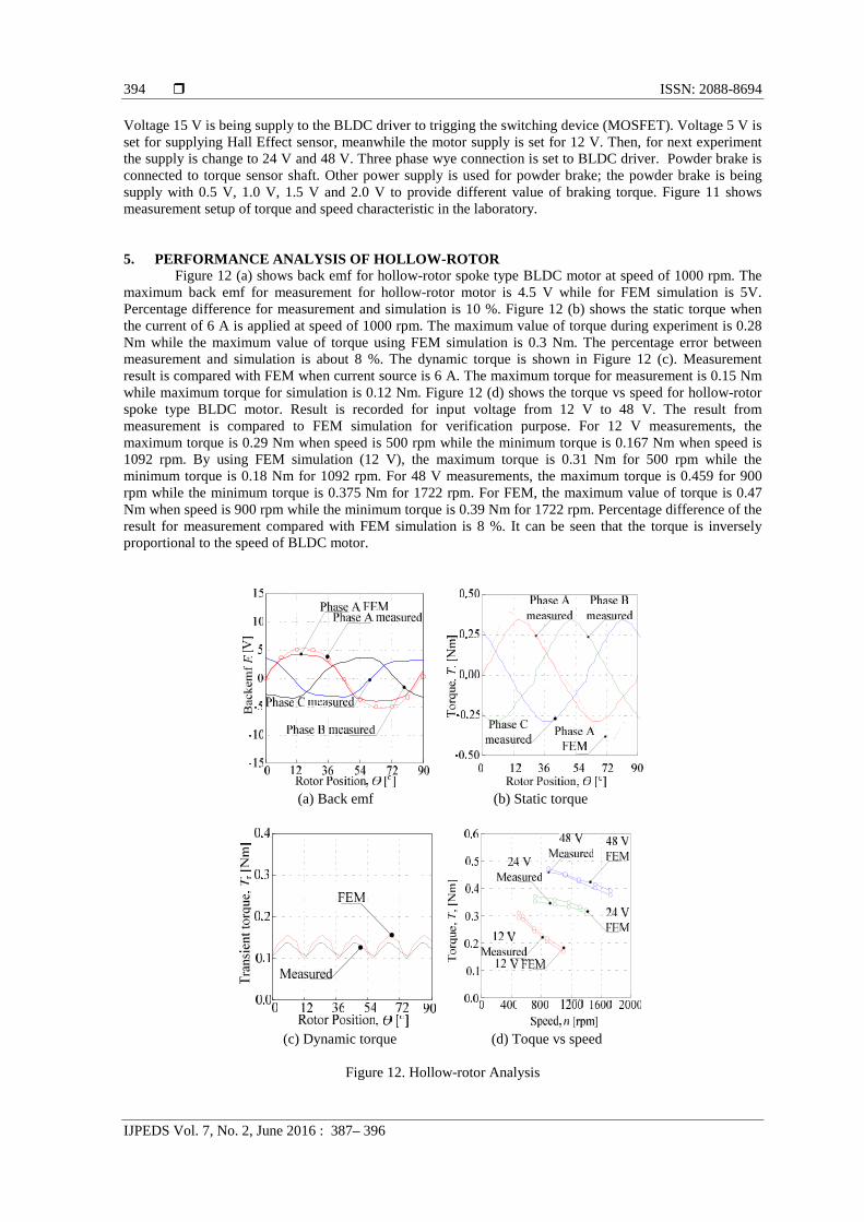
5. PERFORMANCE ANALYSIS OF HOLLOW-ROTORFigure 12 (a) shows back emf for hollow-rotor spoke type BLDC motor at speed of 1000 rpm. The
maximum back emf for measurement for hollow-rotor motor is 4.5 V while for FEM simulation is 5V.Percentage difference for measurement and simulation is 10 %. Figure 12 (b) shows the static torque whenthe current of 6 A is applied at speed of 1000 rpm. The maximum value of torque during experiment is 0.28Nm while the maximum value of torque using FEM simulation is 0.3 Nm. The percentage error betweenmeasurement and simulation is about 8 %. The dynamic torque is shown in Figure 12 (c). Measurementresult is compared with FEM when current source is 6 A. The maximum torque for measurement is 0.15 Nmwhile maximum torque for simulation is 0.12 Nm. Figure 12 (d) shows the torque vs speed for hollow-rotorspoke type BLDC motor. Result is recorded for input voltage from 12 V to 48 V. The result frommeasurement is compared to FEM simulation for verification purpose. For 12 V measurements, themaximum torque is 0.29 Nm when speed is 500 rpm while the minimum torque is 0.167 Nm when speed is1092 rpm. By using FEM simulation (12 V), the maximum torque is 0.31 Nm for 500 rpm while theminimum torque is 0.18 Nm for 1092 rpm. For 48 V measurements, the maximum torque is 0.459 for 900rpm while the minimum torque is 0.375 Nm for 1722 rpm. For FEM, the maximum value of torque is 0.47Nm when speed is 900 rpm while the minimum torque is 0.39 Nm for 1722 rpm. Percentage difference of theresult for measurement compared with FEM simulation is 8 %. It can be seen that the torque is inverselyproportional to the speed of BLDC motor.
(a) Back emf (b) Static torque
(c) Dynamic torque (d) Toque vs speed
Figure 12. Hollow-rotor Analysis
IJPEDS ISSN: 2088-8694
Design of Hollow-Rotor Brushless DC Motor (Raja Nor Firdaus Raja Othman)
395
6. CONCLUSIONIn this paper, the design for hollow-rotor motor has been presented. In the beginning, conventional
BLDC motor is designed, and then analysis process for choosing the right model with proper coil size ischosen. Based on the investigation one BLDC model with reasonable magnet volume is been selected andanalyze in terms of back emf, flux linkage and torque before converted to hollow-rotor BLDC motor. A newmodel structure called hollow-rotor is proposed and result for torque is compared with BLDC motor where itshows increment of torque from 0.19 Nm to 0.39 Nm. For validation, a prototype of hollow rotor spokeBLDC motor had been fabricated. The percentage difference between simulation and measurement is 8 %.This shows that the simulation result has good agreement with the measurement result. As a conclusion, thehollow spoke type topology can be used in designing higher torque to weight ratio of motor.
ACKNOWLEDGEMENTSThe author would like to thank the Ministry of Higher Education, Universiti Teknikal Malaysia
Melaka (UTeM) and Universiti Putra Malaysia (UPM) for providing the funding for the esearch under grantFRGS/1/2014/TK03/FKE/02/F00208 and RACE/F3/TK14/FKE/F00250.
REFERENCES[1] M.A.Salam., Fundamental of Electrical Machines. U.K: Oxford, 2005.[2] M.H.Rashid., Power Electronic, 3rd Edition. Pearson: Prentice Hall, 2004.[3] F.J.Gieras, W. Mitchell., Permanent Magnet Motor Technology, Ohio: Columbia, 2002.[4] A. Balakrishnan., Electrical Machines-1. Engineering series, Perpustakaan Negara Malaysia, 2008.[5] H.G. Kim, J.H., H.G. Sung, and J.P. Hong, “Optimal Design of Spoke Type BLDC Motor Considering Irreversible
Demagnetization of Permanent Magnet,” ICEMS 2003. Sixth International Conference, Vol 1 234-237, 2013.[6] H.G. Kim, J. Hur, W.B. Kim, G.H. Kang, “Irreversible Demagnetization Analysis of IPM type BLDC Motor
Considering the Circulating Current by Stator Turn fault”, Electromagnetic Field Computation (CEFC), 2010 14thBiennial IEEE Conference, 2013.
[7] G.H. Kang, H. Hur, “Analysis of Irreversible Magnet Demagnetization in Line-Start Motors Based on the Finite-Element Method”, Transactions on Magnetics, Vol. 39.No. 4, 1488-1491, May 2003.
[8] B.K. Lee, G.H. Kang, J. Hur, and D. W. You, “Design of Spoke Type BLDC Motors with High Power Density forTraction Applications”, Industry Applications Cobference, Vol 2 1068-1072, 2004.
[9] S.J. Salon, Finite Element Analysis of Electrical Machines, Rensselaer Polytechnic Institute, Troy, New York,1995.
[10] G.H. Kang, J.P. Hong, J.P. Kim, and J.W. Park, “Improved Parameters Modeling of Interior Permanent MagnetSynchronous Motor by Finite Element Analysis”, IEEE Transactions on Magnetics, Vol.36, no.4, 1867-1870,2000.
[11] M.R. Mohammad, K.T. Kim, and J. Hur, “Design and Analysis of a Spoke Type Motor With Segmented PushingPermanent Magnet for Concentrating Air-Gap Flux Density”, IEEE Transactions on Magnetics, Vol. 49, no. 52397-2400,2013.
[12] M.R. Mohammad, K.T. Kim, and J. Hur, “Design and Analysis of Neodymium free Spoke Type Motor withSegmented Wing Shape Permanent Magnet for Concentrating Flux Density”, Energy Conversion Congress andExposition (ECCE), 4991-4997, 2013.
[13] H.W. Kim, K.T. Kim, Y.S. Jo, and J. Hur, “Optimization Methods of Torque Density for Developing theNeodymium Free Spoke Type BLDC Motor”, IEEE Transactions on Magnetics, Vol 49 2173-2176, 2013.
BIOGRAPHIES OF AUTHORS
R. N. Firdaus was born on May 1982 at Parit Buntar, Perak, Malaysia. He received B. Eng.,M.Sc. and Ph.D. in Electrical Power Engineering from Universiti Putra Malaysia. In 2006, 2009and 2013, respectively. He is currently senior lecturer in Department of Power Electronics andDrives, Faculty of Electrical Engineering, Universiti Teknikal Malaysia Melaka. His researchinterest includes applied magnetics, electrical machines, magnetic sensor and drives.
ISSN: 2088-8694
IJPEDS Vol. 7, No. 2, June 2016 : 387– 396
396
S. Farina was born on 14 April 1987 at Malacca, Malaysia. In 2007, she received Diploma inElectrical and Electronic from Infrastructure University Kuala Lumpur (IUKL). In 2012, shereceived her B. Eng., from Universiti Teknikal Malaysia Melaka (UTeM). Currently, she ispursuing her study in M.Sc. in Electrical Engineering from the same university. Her researchstudy is machine design.
R. Suhairi was born on 13 June 1984 at Kota Baru Kelantan. He received the B. Eng. inIndustrial Electronics from Universiti Malaysia Perlis, Malaysia in 2009, and M. Sc. degrees inElectrical Power Engineering from Universiti Putra Malaysia, Malaysia in 2012. Currently he ispursuing his Ph. D. in electrical machine design at Universiti Teknikal Malaysia Melaka. Hisresearch interests are electrical machine design, electric machine simulation, electric drives,energy conversion, and renewable energy.
K. A. Karim received the M.Sc. from University of Bradford and Ph. D. degrees from theUniversity of Nottingham, UK, in 2003 and 2011, respectively. He is currently a Senior Lecturerwith the Department of Power Electronics and Drives, Faculty of Electrical Engineering,UniversitiTeknikal Malaysia Melaka, Durian Tunggal, Malaysia. His research interests includeelectrical machine design, power electronics, and electric vehicle.
A. Jidin received the B. Eng., M. Sc. in power electronics and drives and Ph. D in electricalengineering from Universiti Teknologi Malaysia, Johor Bahru, Malaysia, in 2002, 2004, and2011 respectively. He is currently a Lecturer with the Department of Power Electronics andDrives, Faculty of Electrical Engineering, Universiti Teknikal Malaysia Melaka, DurianTunggal, Malaysia. His research interests include the field of power electronics, motor drivesystems, field-programmable gate array, and DSP applications.
T. Sutikno received the B. Eng. degree in electrical engineering from Diponegoro University,Semarang, Indonesia, in 1999; the M. Eng. in electrical engineering from Gadjah MadaUniversity, Yogyakarta, Indonesia, in 2004 and Ph.D. in electrical engineering from UniversitiTeknologi Malaysia, Johor Bahru, Malaysia, in 2016. Since 2001, he has been a Lecturer withthe Department of Electrical Engineering, Faculty of Industrial Technology, Universitas AhmadDahlan, Yogyakarta, Indonesia; and since 2008 he is an Associatee Professor. His researchinterests include the field of power electronics, motor drive systems and field-programmablegate array applications
M. Norhisam received B. Eng, M. Sc. and Ph. D from Shinshu University Japan in 1998, 2000and 2003, respectively. He is currently an Assoc. Prof at Department of Electrical andElectronic, Faculty of Engineering, Universiti Putra Malaysia. His area of interest is appliesmagnetic, magnetic sensor, electrical motor design, electrical generator design and powerelectronic.