Embed Size (px)
Citation preview

Scholars' Mine Scholars' Mine
Bachelors Theses Student Theses and Dissertations
1923
Design of high tension outdoor substation Design of high tension outdoor substation
Joseph Worley
Follow this and additional works at: https://scholarsmine.mst.edu/bachelors_theses
Part of the Electrical and Computer Engineering Commons
Department: Electrical and Computer Engineering Department: Electrical and Computer Engineering
Recommended Citation Recommended Citation Worley, Joseph, "Design of high tension outdoor substation" (1923). Bachelors Theses. 181. https://scholarsmine.mst.edu/bachelors_theses/181
This Thesis - Open Access is brought to you for free and open access by Scholars' Mine. It has been accepted for inclusion in Bachelors Theses by an authorized administrator of Scholars' Mine. This work is protected by U. S. Copyright Law. Unauthorized use including reproduction for redistribution requires the permission of the copyright holder. For more information, please contact [email protected].

DRSIGN OF HIGH TENSION OUTDOOR SUBSTATION
BY
A
THESIS
submitted to the faculty of the
SCHOOL OF MIKES AND METALLURGY OF THE UNIVERSITY OF MISS~
in nartial fulfillment of the work required for the
Degree of
BACHELOR OF SCIENCE IN ELECTRICAL ENGINERdING
1923
£ W~- .. ..
Apnroved by--- ..E...- ----,~~c:;..-~......-~-----Professor of Electricaf ~ngineering.

DESIGN OF HIGH TENSION OUTDOOR SUBSTATION
This thesis deals with the selection and arrangement of
the equipment used in high tension outdoor sUbstations.
Joseph WorleYe
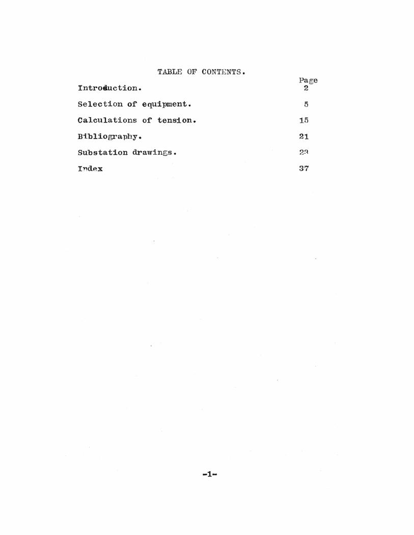
TABLE OF CONTENTS.
Introduction.
Selection of equipment.
Calculations or tension.
Bibliography.
Substation drawings.
Indp.x
-1-
Page2
5
15
21
37

Suggested Procedure in SUbstation Design
aMental picture of layout.1.bSingle line diagram of connections.
aSelection of equipment,with given capacity and loado
2.bSnacing and influential factors must be considered.
3,aSketch and indicate the equipment in its selected place.
Equipment includes oil switches,transformers,suspension
disconneeting swicches,buses,ligbtning arresters,and
choke coils.
4aDetails of above should be drawn freehand in order to
'get an idea of the proper arrangement and the necess-
ary 10cations.It might be we~l to cut out some small
templets and arrange them in the best order that would
give the proper spacing required.
5QClearances should be cheeked.
Size of wire and size of buses must conform with minimum
allowable values.
Insulators must be of such strengah in order to with-
stand any mechanical or electrical strain.
eaAll equipment must be checked up for final selection.
7a.A material list should be drawn up including all equip-
and necessary apparatus used in the SUbstation.
BaDesign should be started at the transmission lines and
and finished at the secondaries of the Toltage trans-
rormers.
-2-

The present day tendency appears to be toward the more
rrequent use or outdoor sUbstations.Where not only the
section disconnecting switches,but also transrormers,
lightning arresters,and indeed all high tension equip
ment,are exposed to the weather.The eontrol or loeal
feeder eircuits at the lower pressures would be by means
of switch-panels in cheaply eonstructed houses ereeted
near the transformers.
When the Toltage is high, the clearances required by the
high-tension leads and bus-bars within a substation may
require a large building and henee a considerable invest
ment.The investment in equipment and in buildings situat-.ed along transmission lines and supplying small loads
may be large eompared with the kilowatt-hours consumed.
Substations ror small loads would not be economically
possible were it necessary to place all the apparatus
within a bUilding.Transformers,switches,lightning arrest
ers ,have been designed so that it is possible to operate
them out of door••Tb~ bUilding needs only to house the
switchboard and the operator,ir one is necessary.The oil
switches, the light*ing arresters, the transformers,and the
bus-bars CaD alr'lbe placed out or doors.The apparatus
must be prachically air tight to keep out moisture.out-
door SUbstations on a large seale are highly developed at
the present timeo
-3-

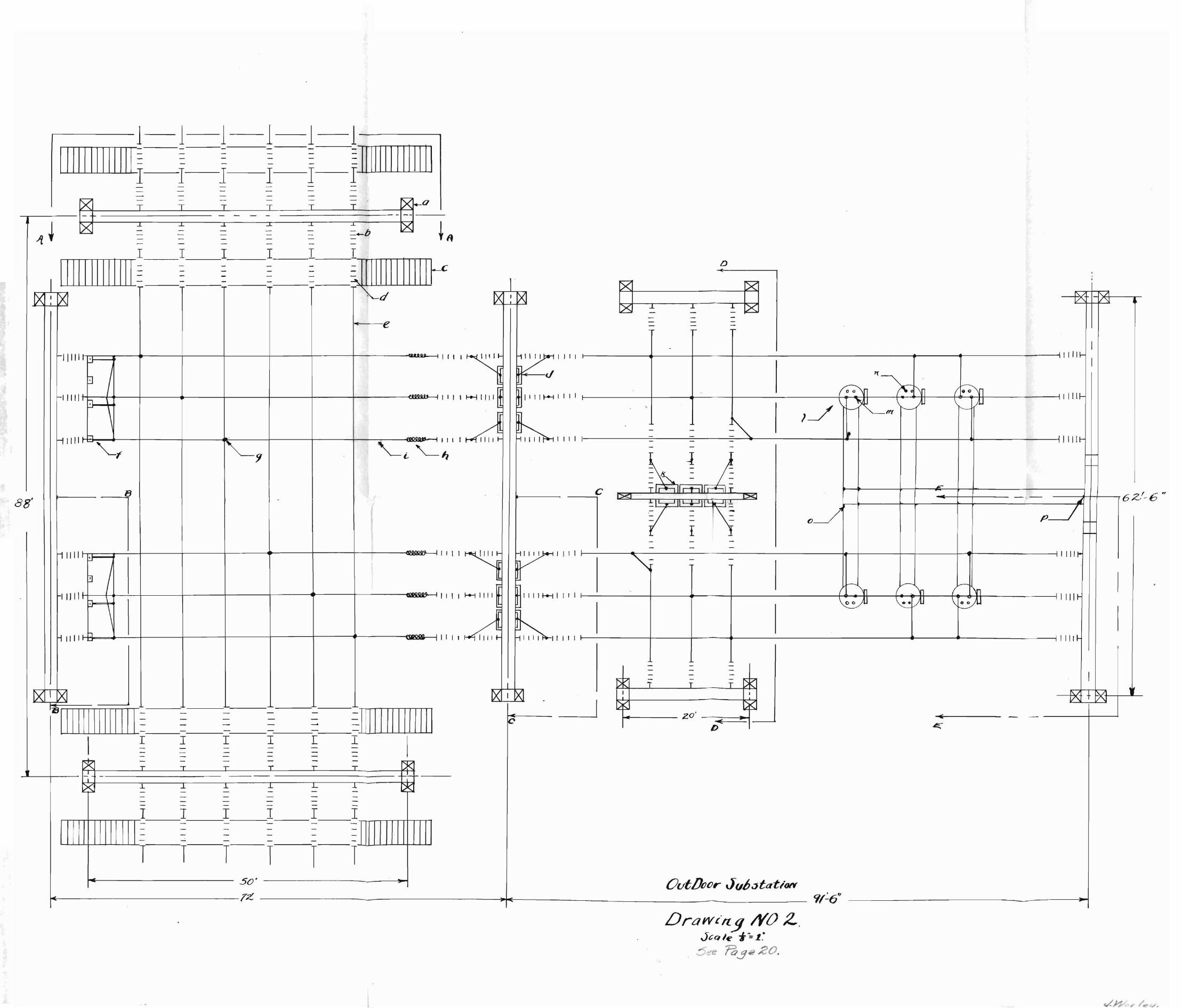
A very desirable arrangement of the transmission lines
and apparatus is obtained in the outdoor substation as
shown in drawings.NOol and NO.2.The two three phase
66,000 / 6,60 0 volt ~ransformers are fed from the same or
separate transmission lines.They may also feed these trans
mission lines if their secondaries are connected to a gen
erator bus by means of an oil switbh.The load on one trans
mission line may be shifted by means of the bus tie within
the station.
This design brings out the simplicity and the flexibility
of arrangement which may be obtained where the space is
not limitedoWith unlimited space fUture provisions may be
made thus avoiding changes in the structural arrangement
when the power demand increases.The only changes which
would be necessary,would be to change the position of the
transformers.Enough space is provided for such that the
change ~ould be made within a few hours upon notice given
by the consumero
This sUbstation may be used as a unit of a High Tension dis
tributing system, such as a ring system with generating stations
and sUbstations at various points in the systam.The sUbstation 11
may be used to distribute the power from the transmission ~ine
or it ma. be used in supplying power to the transmission line
f'rom a generati:*g station.In using two banks of transformers <d"l{l
-4-

and a double circuit it of'f'ers many advantages SUChi.laS great
er reliabi~ity of' service, easier main~enance and repairs.
It can be seen in the general wiring diagram that a bus-tie
is used,This of'f'ers several advantages in that the load on one
transmission line may be shif'ted to the other and thus should
there be any interuption in sevice due to a short circuit on
one transmission the load can be immediately switched to the
other parallel line and the truuble can be permanently repaired.
There is one way in which the designer can design a station o~
the correct capacity and then as industrial condi tl. ons change
the capacity of' the station may not be large enough to supply
the power demand,so it remains f'or him to assume some app.rent
load keeping in mind that a greater load demand might occur in
the future.
The capacity of' this particular sUbstation is 3000.00 IT.V.A.
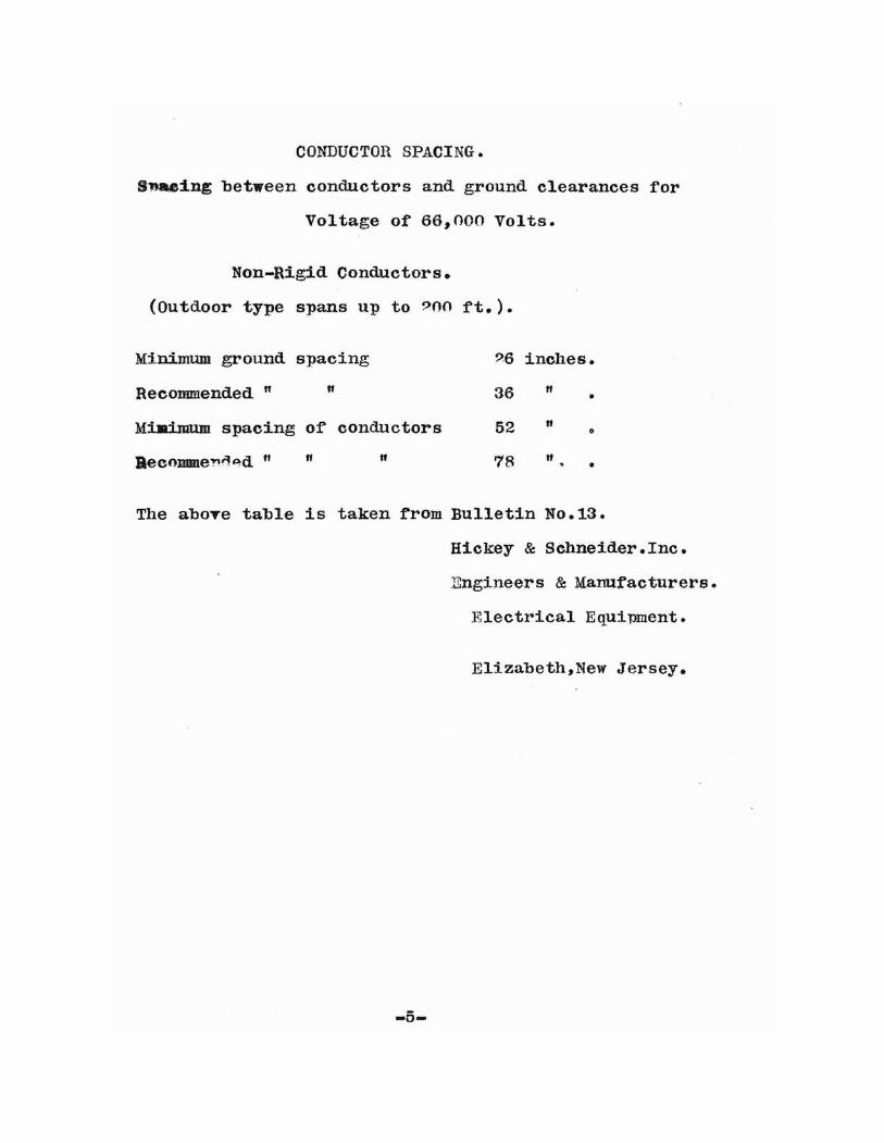
CONDUCTOR SPACING.
S.,.a.eing between conductors and ground clearances for
Voltage of 66,000 Volts.
Non-Rigid Conductors.
(Outdoor type spans up to 900 ft.).
Minimum ground spacing 96 inches.
Recommended " " 36 " •
MiAimum spacing of conductors 52 " 0
Beeomme'!'~~d " If " 78 It •
The aboTe table is taken from Bulletin No.13.
Hickey & Schneider. Inc.
Engineers & Manufacturers.
Electrical Equipment.
Elizabeth,New Jersey.
-5-
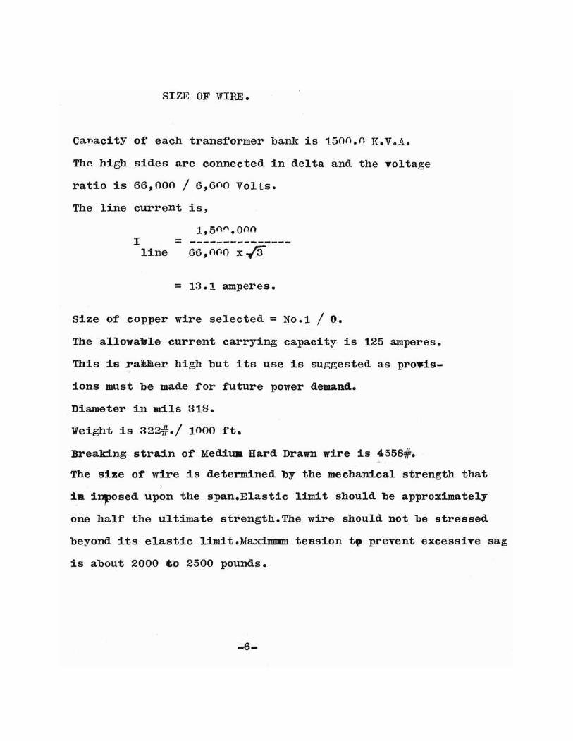
SI ZE OF WIRE.
Canacity of each transformer bank is 1500.n K.VoA.
Thp. high sides are connected in delta and the Toltage
ratio is 66,000 / 6,600 Volts.
The line current is,
1,50n ,onnI = ---------------line 66, noo x-13
= 13.1 amperes.
Size of copper wire selected = No.1 / O.
The allowavle current carrying capacity is 125 amperes.
This is raner high but its use is suggested as pro..is-
ions must be made for future power demand.
Diameter in mils 318.
Weight is 322#./ 10 00 ft.
Breaking strain of Medina Hard Drawn wire is 4558#=.c.
The size of wire is determined by the mechanical strength that
iB i~osed upon the span.Elastic limit should be approximately
one half the ultimate strength. The wire should not be stressed
beyond its elastic limit.Max1mmm tension tp prevent excessiTe sag
is about 2000 GD 2500 pounds.
-6-

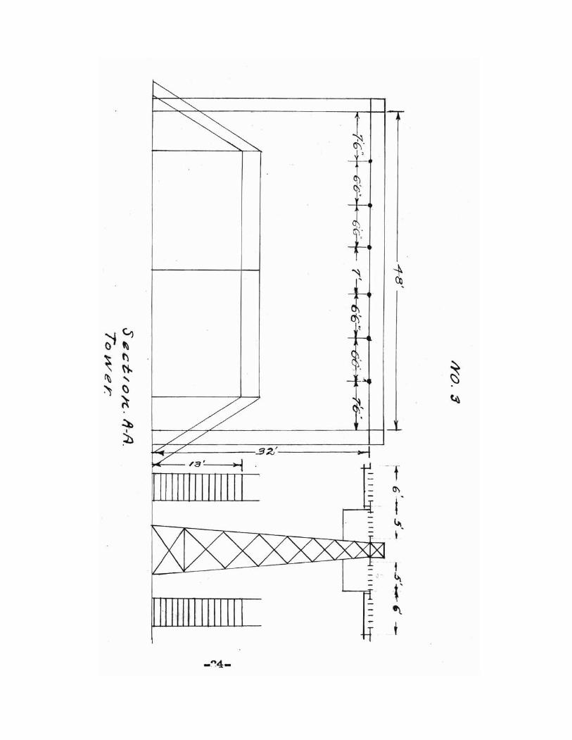
TOWERS.
Towers are to be or the A-frame type and are to be design
ed by the stryetural engineers. The mechanical stress and
strain can be obtained rrom the calculations on Sago The
height and width can be found in the sectional drawings
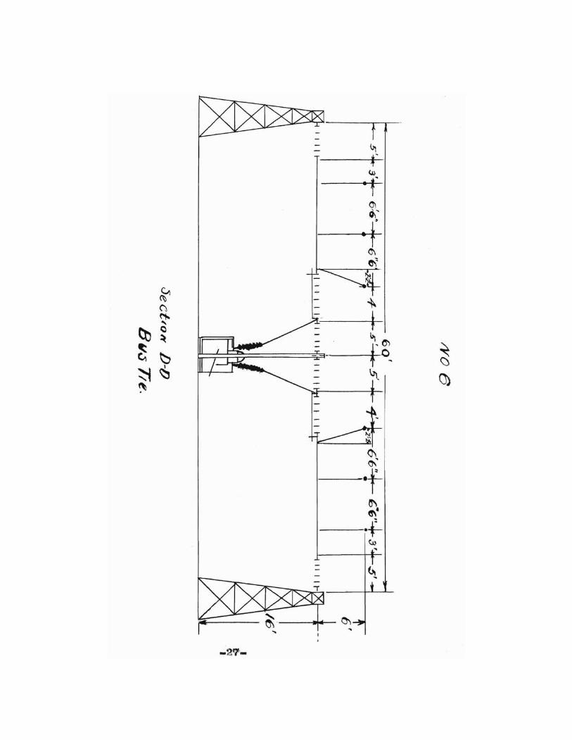
Nos.3,4,5,6,7o.A factor of safety of not less than ~
shall be used as provisions must be made for a change in
the ruture.
In diagram No 1.and in drawing N03.it will be seen that ladders
are used this ma~ not be obvious but they are used since the~~~
length of disconnecting switcbJ\! are about 20 ft,long.The switch-
es are 32 ft.from the ground and it would be impossible for an
operatir to be able to open them unless these ladders were used
for this reason I find it necessary to malce some device where
by the operator can open the 'disconnecting switches without
much trouble and time on his part.
~-
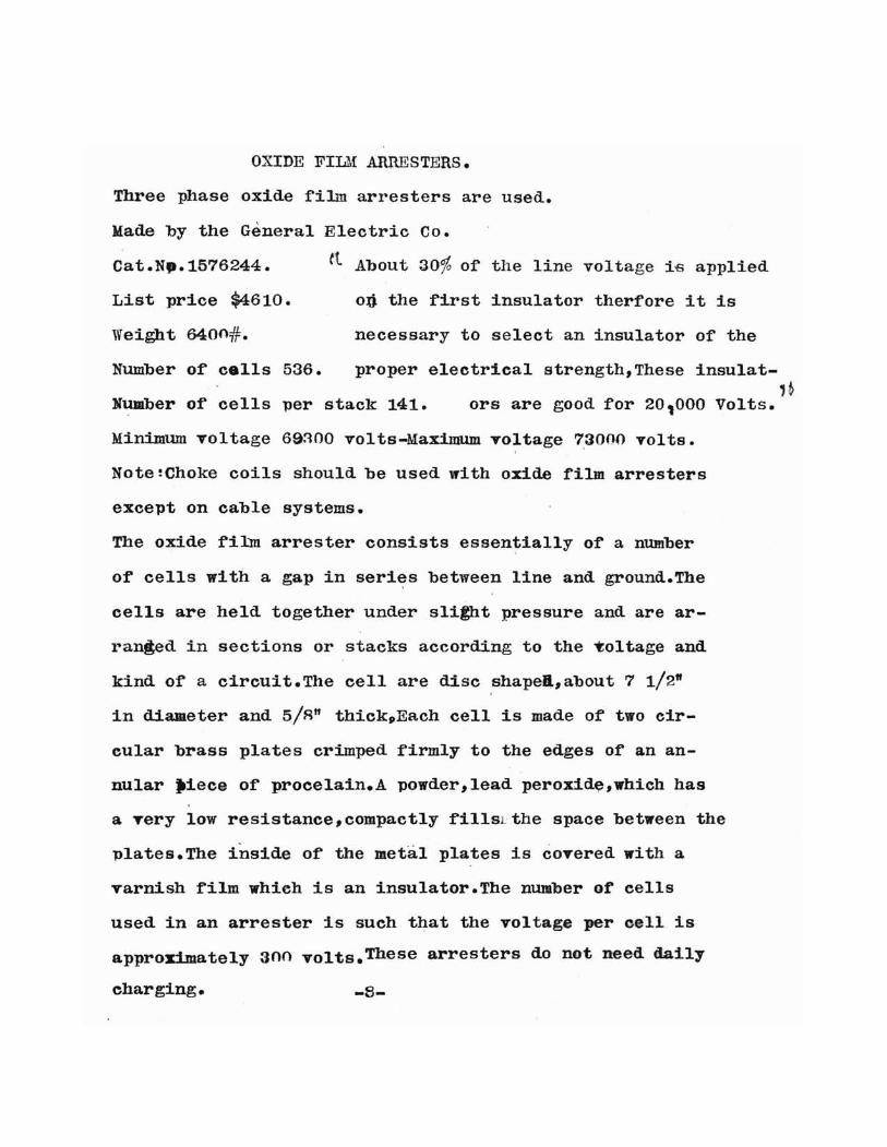
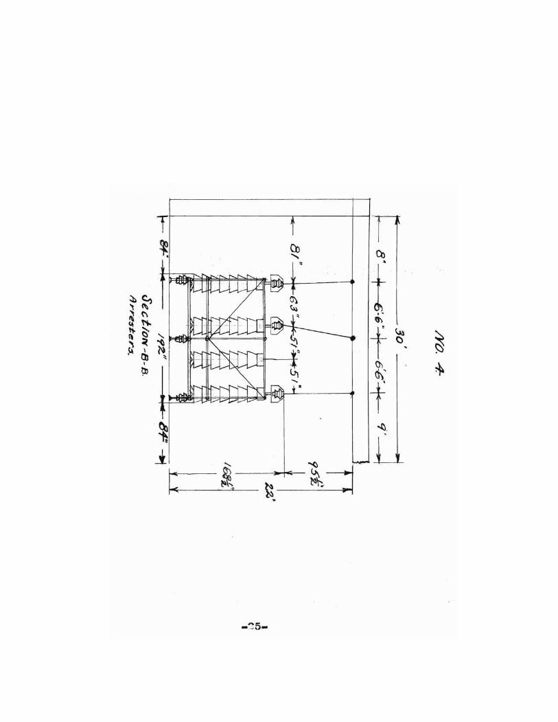
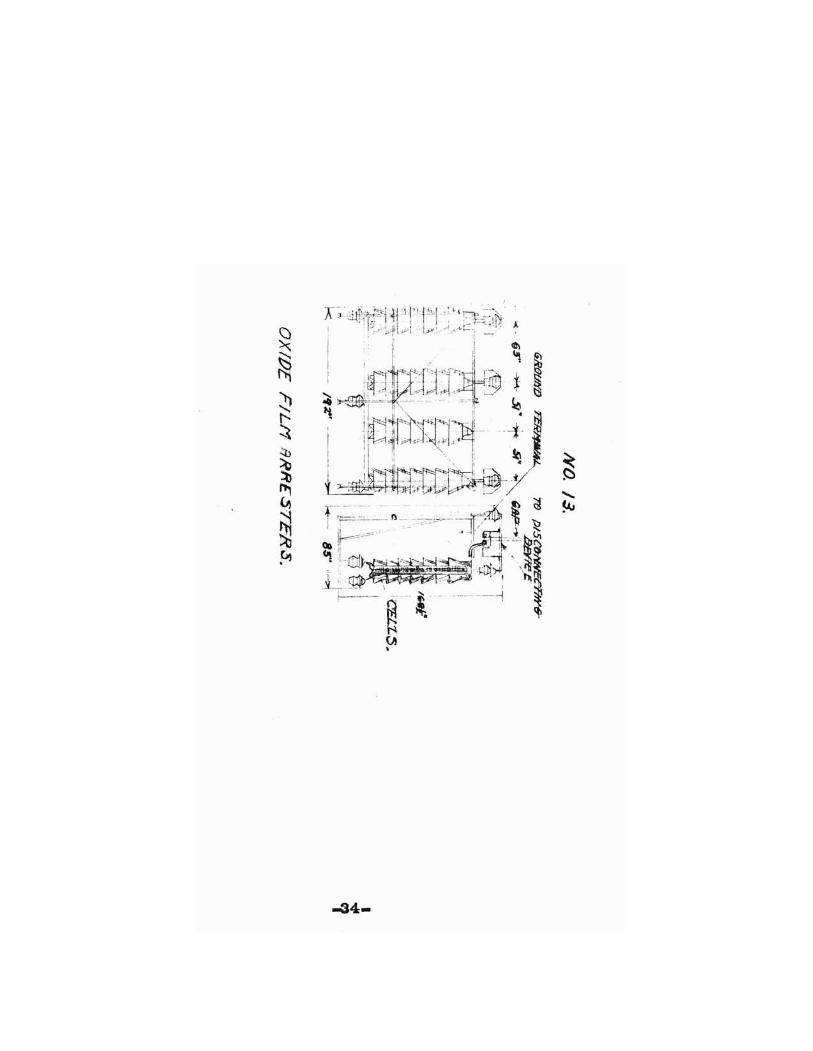
OXIDE FILM ARRESTERS.
Three phase oxide fiLm arresters are used.
Made by the General Electric Co.
Cat.Np.1576244. tt About 30% of the line voltage i£ applied
List price $4610. 03 the first insulator therfore it is
Weight 6400 #. necessary to select an insulator of the
Number of cells 536. proper electrical strength, These insulat-1h
Number of cells per stack 141. ors are good for 20,000 Volts.
Minimum Toltage 6a~OO volts-Maximum voltage 73000 volts.
Note~Choke coils should be used with oxide film arresters
except on cable systems.
The oxide finm arrester consists essentially of a number
of cells with a gap in seri~s between line and ground.The
cells are held together under slilht pressure and are ar
ranged in sections or stacks according to the ~oltage and
kind of a circuit.The cell are disc shapel,about 7 1/2"
in diameter and 5/R" tbickpEach cell is made of two cir
eular brass plates crimped firmly to the edges of an an
nular ~iece of procelain.A powder, lead perox1d~,wbich has
a Tery low resistance,compaetly fillsLthe space between the
plates.The inside of the metal plates is cOTered with a
varnish film which is an insulator.The number of cells
used in an arrester is such that the Toltage per cell is
approximately 300 volts.These arresters do not need daily
charging. -s-

OIL SWITCIIES(CIRCUIT BHEAKERS).
Three phase oil circuit breakers are used.
:Made by the Westinghouse Electric & Manu:racturing Cpo
Type GA Oil Circuit breakers. OUTDOOR TYPE.
Hand-operated.
Automatic.
style No.163515.
Voltage 66000 volts.
Shipping weight 7500#.Net weight 550n#.
Gallons pf Oil 360.
Note: Weight does not include oil.Weight of' oil is appro~
imate1y 7 1/2 pounds per gallon.
The bushing on these oil switohes are to be equiped with bush
ing type current transformers, this will enable the oil switch
to open on some predetermined value of' the line eurrent o
-~-

Transformers.
Single phase transformers are to be used.
Made by the General Electric Co.
Canacity 500 K.V.Ao
Voltage Ratio 66000 / 6600 Volts.
Frequency 60 cycles.
Type Out door-~~~. Oil-Cooled.
weights with oil =22?OO#.
Comnlete without oil =1~nno#_
To be lifted from tank for inspection 7~OO#.
Transformers have pipe tap connections for filter press.
Caution:Lines or buses connected to these transformers
should be supported such that no appreciable weight or
mechanical stra~n is imposed on the transformers terminals.
The mransformers are connected Delta on the high side and may
be either connected in wye or delta on the low side according
to what eTBr connections are aesired.
-10-
CHOKE COILS-SUSPENSION SWITCHES & SUSPENSION INSULATORS.
The choke coils,suspellSioll disconnecting switches and sus
pension insulators,assehlbly were selected :from I.H.J.Jovett's
design book.
Anderson disconnecting switches are used in ,combination
with the insulators of the O.B.type.
Insulator units are made by the Ohio Brass Co .dansfield, Ohio.
Six insulators are used for a line voltage of 66000 volts.
-11-
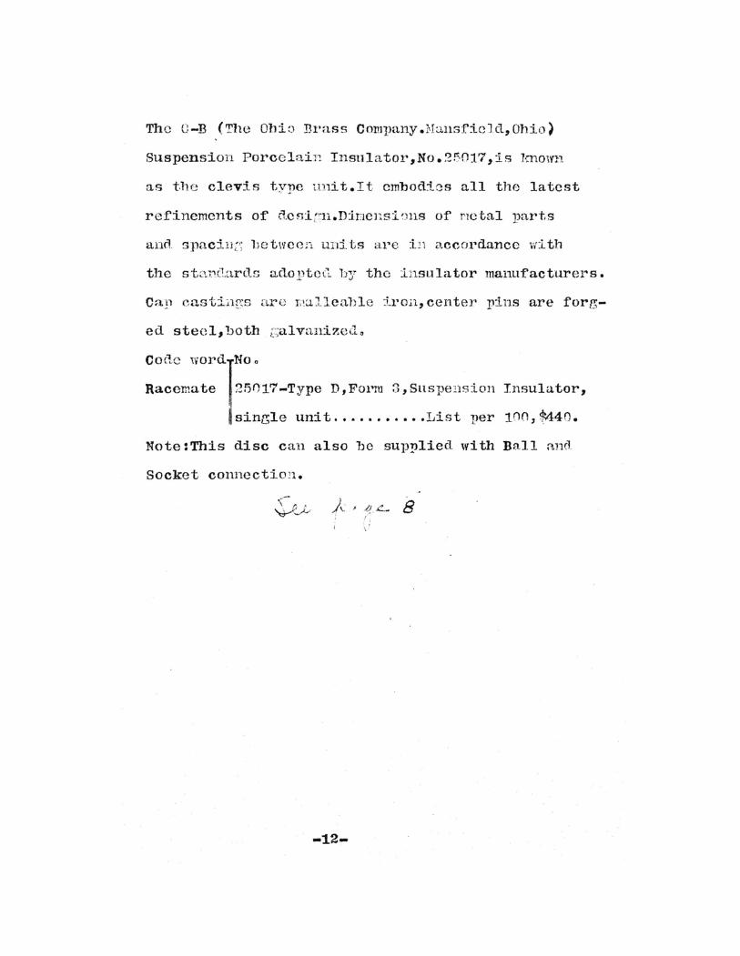
The C-B (The Ohi:) Brass Company.Hansficlcl,Ohio)
Suspension Porcclai}, Insulator,No.2!:-017,is lmown
as tbe clevis type unit.It embodies all the latest
refinements of ::lcsi:r.l1.Dir]CllSi~JllS of nctal parts
and spacili2; lJetwccl1 uHi ts al'e :lli accordance wi tIl
the st::''..l''(l.ards 3,(10 ptOCL by the :Lnsu la. tor manufacturers.
Call eastii.lgs are l;~:.lllealJle iron, center pins are for/?;-
ed steel, both ;:;alvanizedo
Coclc wordlNO 0
Racemate 25017-Type D,Fol'm 3,SUSpe!lSion
sinr;le unit ......•.•.•List per
Insulator,
100, $440.
Note :This disc can also lJC supplied with Ball and.
Socket connectio'l.
-12-
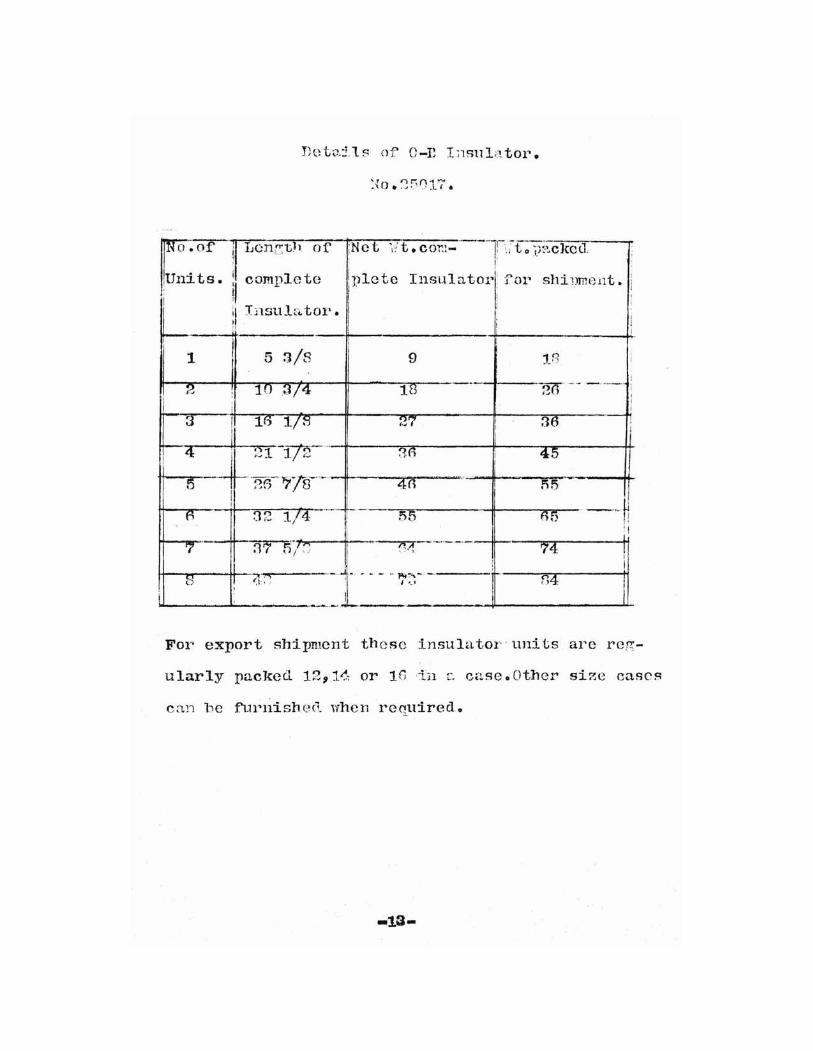
Det ..:51 s of O-E I~lsulator.
INo .of 1Len~th of ;Net ',it. cor.:- -r;;t 0 ~-;~'.,c](el1-! '-' -- - 1'- --
Units. II complete iplete lusu1 a tor' for shi1Jment. ;I: II ! ,
il Insulator.I
I
~, ; I: I
/i
1 5 3/8 9 "In i
.6 -§'f-- ----;2 : 10 3/4 18 I..J J I
i : II
3 1[) 1/8 27 36 ;I II
I4 21 -172--- 36 I 45 II
--~ ------fj1i----- --nI
26 8 4(1I
n!5I
I --oM32 1/4 --- r- 55{i 05 Ii'I-- f-~-' - -,......-_.-- I
7 3 f,;' ,j 1'0 74 !,. ':
_. ..1 : I().;1
~... .. .. .- -.. !"I~-" f14t.i ,I ~_,
Ii , I-- -~~-.. .. - -
For export shipment these insulator'units are reg-
ularly packed 12,1<1, or 10tn f" case. Other si~e cases
can be f''Lll~nishe("t whell required.

(APurox ) •
MATERIAL LIST.
Name.
Transformers
Oil Switches(three phase)
Lightning Arresters(three phase)
Choke coils
Anderson Disc.S~itch
G.B.Insulator Units
Disconnecting sticks
Wire No.1 / 0
Three bolt clamps
CleTises (Roller).
Eye Bolts. 5/8" ~ 19."
Loeke Clevis No 2937.
Quantity.
6
:l
2
6
42
:.12
2
1700 feet.
90
90
60
60
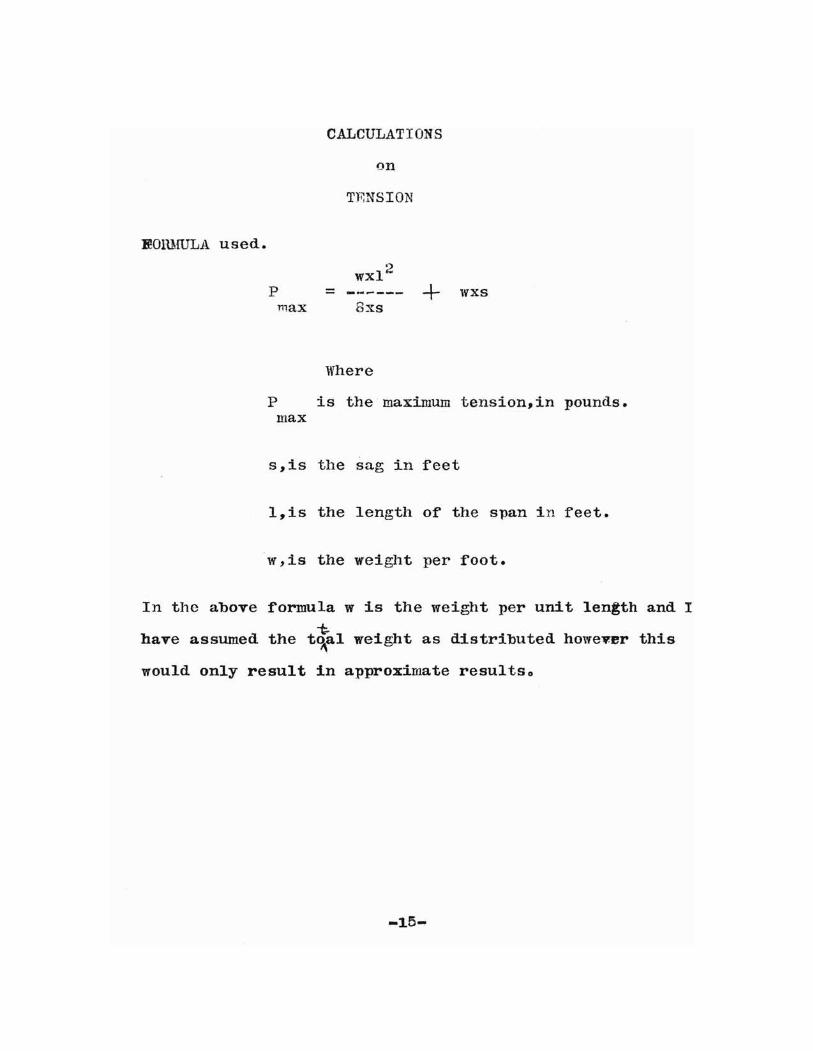
CALCULATIONS
on
TENSION
IwmmLA used.
wx1 2
p = ------ ~ wxsmax 8xs
Where
P is the maximum tension, in pounds.max
s,is the sag in reet
l,is the length or the s-pan in reet.
w,is the weight per root.
In the above formula w is the weight per unit len~th and I
-t:.have assumed the t~al weight as distributed however this
would only result in approximate resultso
-15-
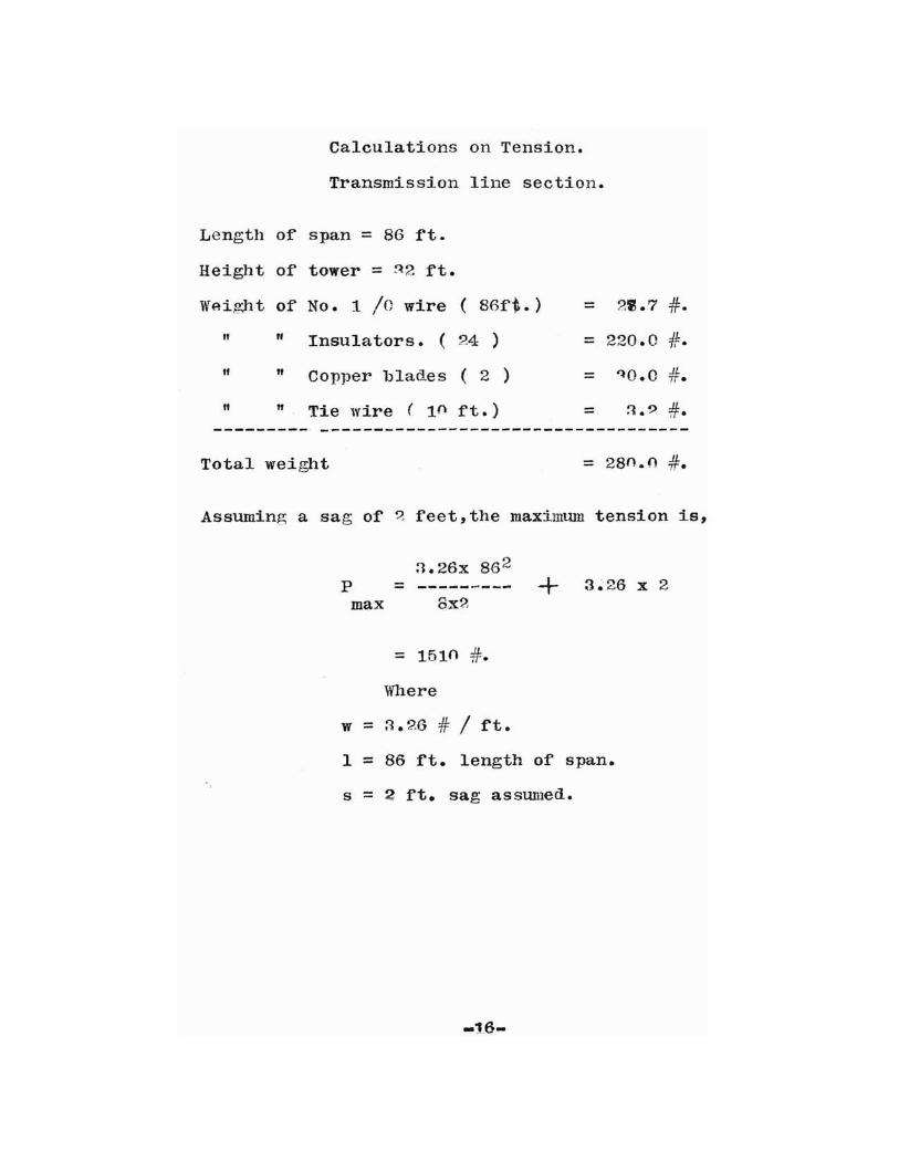
Calculations on Tension.
Transmission line section.
Length of span = 86 ft.
Height of tower = ~2 ft.
WAi.ght of No. 1 /0 wire ( 86:f~.) = 2'.7 #.
" If Insulators. ( 24 ) = 220.0 #.
" fI Copper blades ( 2 ) = "lO.O #.
" " Tie wire ( 1(\ ft.) = :1.? #.
Total weight = 28fl.{) #.
Assuming a sag of ~ f'eet, the max:irnmn tension is,
:1.26x 862
P = --------- + 3.26 x 2max ox?
= 1510 #.
Where
w = :1.26 =#= / f't.
1 = 86 ft. length of span.
s = 2 :ft. sag assumed.
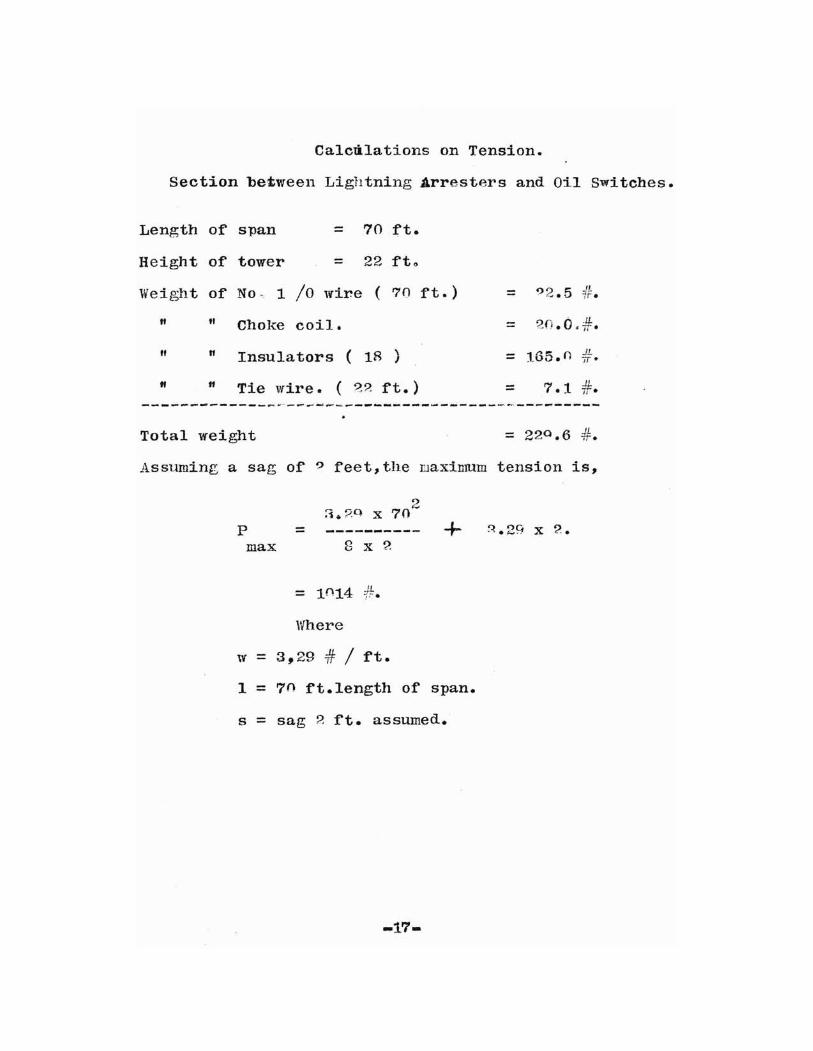
Calcdlations on Tension.
Section be'tween Lightning Arresters and 01.1 Switches.
Length of s-pan = 70 ft.
Height of tower = 22 :ft"
Weight of No, 1 /0 wire ( 7() :ft.) 92.5 "= =tf.
H " Choke coil. = 20.0.#.
tt " Insulators ( is \ = 165.0 J1.J ir·
" " Tie wire. ( ~? :ft.) = 7.1 ..u.iJ·
Total weight
Assuming a sag o:f 9 feet, the maximum tension is,
max 8 x 2p =
:1. ?Q X
+ ~.2q x 2.
Where
w = 3~29 # / :ft.
1 = 70 ft.length of span.
s = sag 2 :ft. assumed.
-17-
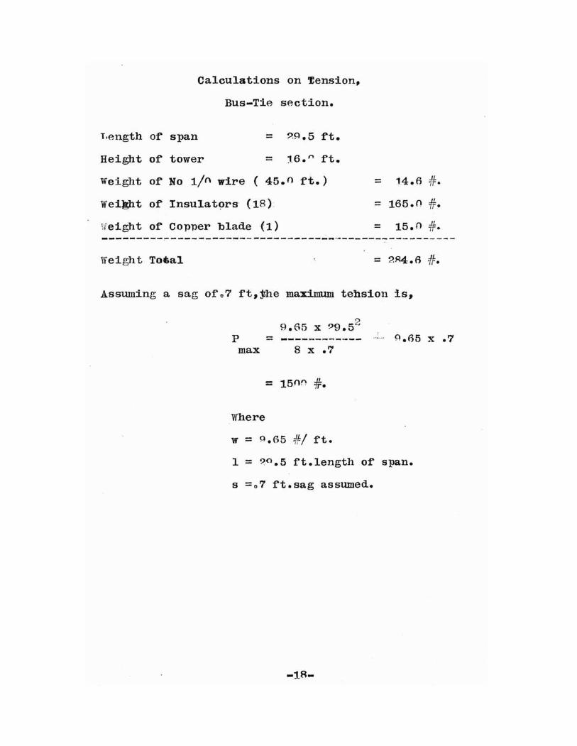
Calculations on ~ension,
Bus-Tie section.
T,ength of span = ?~.5 ft.
Height o:f tower = 16. n. ft.
Weight of No lIn wire ( 45.() ft.) = 14.6 #.
Weight of Insulators (18): = 165.0 #.
Weight o:f Copper blade (1) = 15.0 #.---------~------------------------~-----------------
Weight Toeal
Assuming a sag of 0 7 ft,jhe maximum tehsion is,
9.65 x ?9.52
P = ------------max 8 x .7
= 150rl #.
Where
w = 0.65 #/ ft.
0.65 x .7
1 = ?o.5 ft.length of span.
s =07 :ft.sag assumed.
-lR-
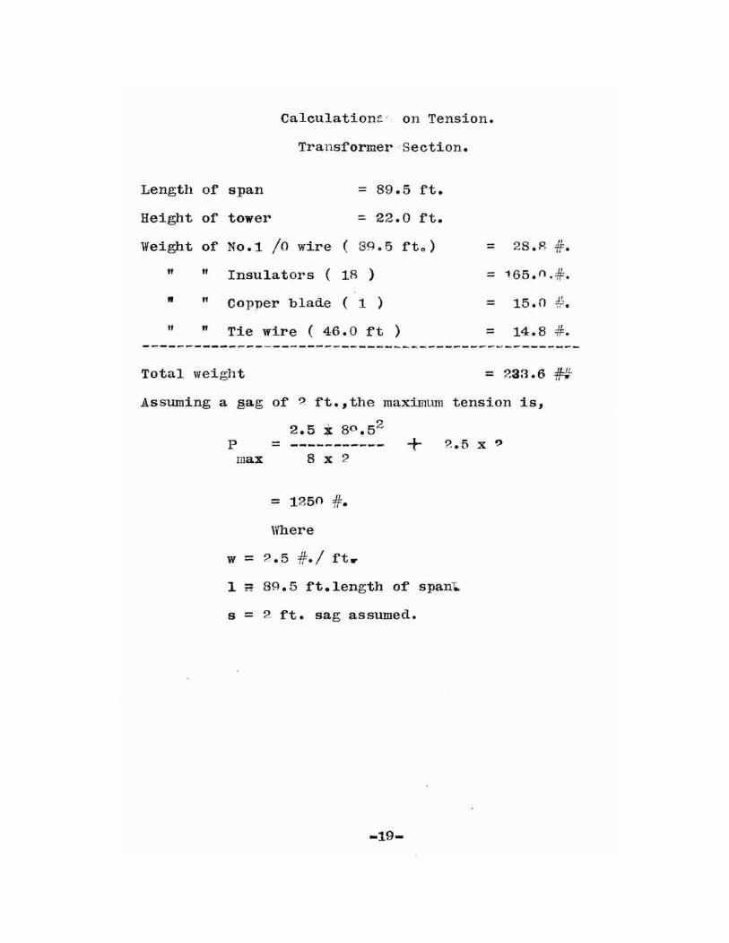
Calculationc- on Tension.
Transformer 'Section.
Length of span
Height of tower
= 89.5 ft.
:: 22.0 :ft.
Weight of No.1 /0 wire ( tN.5 l'to) = 28.R i.ff tI Insulators ( 18 ) = 165. 0 ·:1f.
" " Copper blade ( 1 ) = 15.0 :#:'..It " Tie wire ( 46.0 ft ) = 14.8 =H=.
Total weight = 233.6 HAssuming a §ag of ? ft.,the maxiulUID tension is,
2.5 i 80 .52
P = ----------- + 2.5 x 9
max 8 x 2
= 1250 #=.
Where
w = 2.5 #=./ f't ..
1 rt 8~.5 f't.length of' span~
s = 2 ft. sag assumed.
-19-

REFERENCE PAGE FOR DRA1YING NO.1.
Item
A-A
B-B
Name Drawing No.
Longi. tudinal.C. S. 3
Blevation.C.S. 4
Page.
?5
C-C
D-D
E-E
a
b
c
"
""
Towers
Insulators
Ladders
" "" "
" "
5
6
7
3
8,9,10.
3
?6
:'.8
:'.9-31
d
e
f'
g
h
i
j
1I
m
n
Disc.Switch.
NO.1/0 M.ll.D wire.
Lt.Arresters.
Tie line
Choke coils
Substation Bus
Oil switches
Bus-Tie
Transf'ormers.
IIi-side of' trans.
Low-side of' trans.
11
4,1~
12
5,14
6
7,15
32
32
~6,35
27
28,36
o
p
Tracks f'or transf'ormers. 7
Lif'ting tower f'or trans. 7
28

BIBLIOGRAPHY.
Electrical World Volume Pagp.
6Q 819
70 98
70 100
70 1236
71 718
70 689
72 537
72 928
72 1068
73 788
73 831
73 884
78 132f.
79 681
75 433
75 139
75., 883
75 949
75 827
75 955
74 1110
"77 1315
66 689
-21-
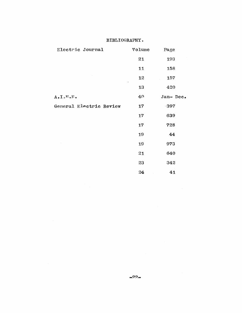
BIBLIOGRAPHY.
Electric Journal Volwne Page
21 193
11 158
12 157
13 420
A.IoP..F. 40 Jan- Dec.
General EIActric Review 17 397
17 639
17 728
19 44
19 973
21 640
23 342
24 41

")(''!!Jllrreder~
~~<::
~~~
;r-~'
~~r-+-. ~
:r--Coil.
""'" ~DOD a0 0 L!!JlJt
. Cfoke
T~•

~'------ ~ ----~
- ~~ ---~-~ -~-....
.. ...,~ .~
~,
-1 J.~~ \f)
~ .~~-1 1 ~\jQ
~ I ~
~ :~ ~ ~.~~lf)
~.0 .....
-1.....,. ~ \)
~~ ".~ ~
1co
"'"f-~
IfC'i~'
.t-C\~
~ ~~~
~(';0.....
~Q
~~
f~~ ~~ ~ -'- \:)
~~ - ~, (J)!\
tl'\f!r\-
I--.f-<:l.>..
-27-

-25- .
Ckl..
t\l\ I
~'•

/YO 8
C-B Sl1SrHJJlsi.on P 1'cc1n1n Insulator.
Type J),Form '. -Patented
___.l::::;::==-====:::::;;::l:-:::£---'_
Two units,No o 25017,connectcd;lower unit
shown in section.
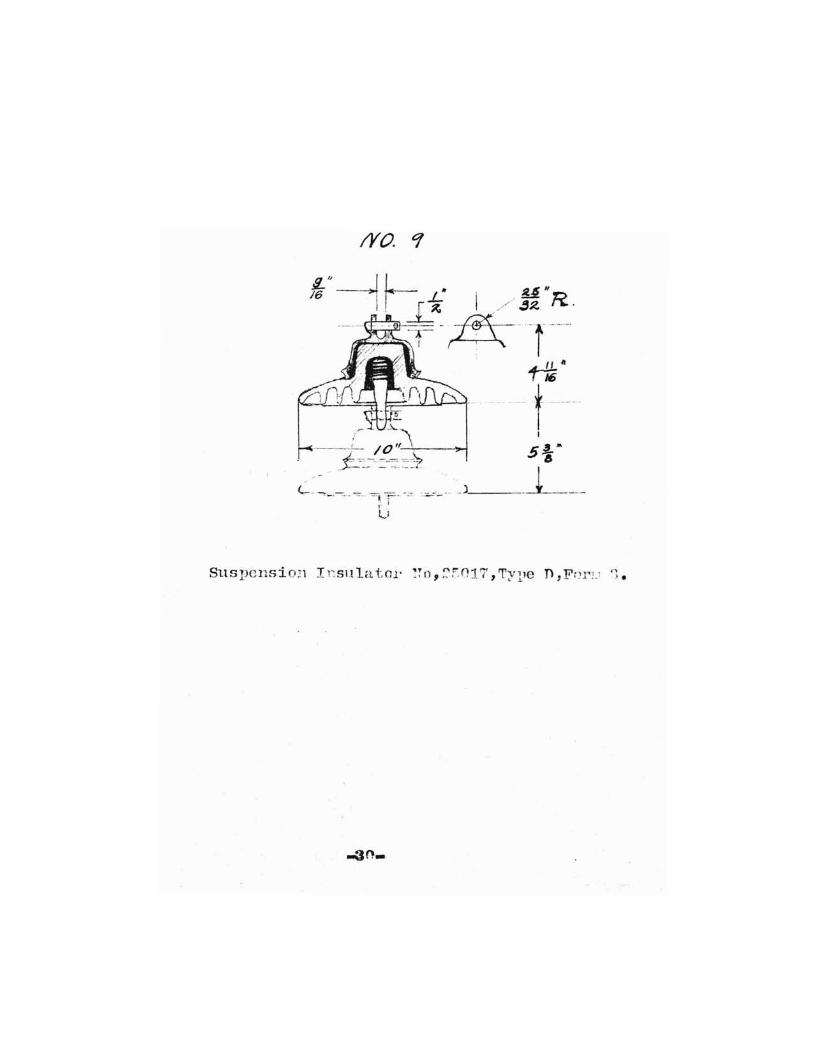
/YO. q
Suspension Irsula tor ~~o, :::::'017, 't'ype n, F(~r!.1 '1.

(YO. /0.
Deaf} End wi.th Tur,l Buckle for' Gf1,800 Volt Sul}-
st:l.tJon.
Dead. Bnd on Steel Gil'ller.g~<fc: Bolt userl on d.eai.1. end. •
..
1. Servii.1C.
2.Three Bolt Clamp A.To&
:~ "noller Clevis.
."
jl',;
T • Pl:.... t tern ..
~.Suspension Disc .. o.n.No.2~OI7g
6 .. 5/f?" xIS" Rye Dolt, threa(led lfl", & h<,.. s 2 nuts & 1 washer.

IVa / I.~)llspension Disconi.ec. tinn' Swltch For ()6, ono Volt
Substation.
1.See Drawing NO p 8 't ,.
2.Serving.
3.Iloller UleTis.
4.Suspension Disc,O.B.No.2~017.
~.Anderson Suspension Disconncctill~ Switch.
6.Three Bolt Cla~p A.T.&T.Pattern.
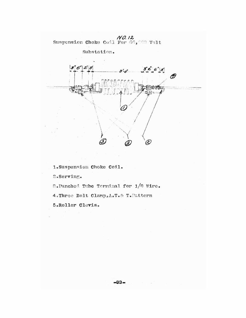
1Yl7.IZSuspension Choke Cu:U For Ci(;, "',:.r) Volt
Sul)statinn.
\,\
\
11.Suspension Choke Coil.
2.Serving.
~. Punchecl Trlhe Terrdnal f'or lin Wire.
40 Threo Bolt ClaMp ,AoT 0 8~ T .r;:.. t tern
5.Roller Cleviso

NO./-f:Wcstiu.:-hons0 ~'~'~ctl':'ic & E;1mLf':,-ctnr:i..nrr Co.
East T'itts1nH':~11,Pao
Type GA Oil Circuit-Breaker.
style No.163515oVolts RoOOO.
Net wt.55,)';:'!: vithout o:il.Gals 0;1 :l!~f).

~~ f~
'::
~
.,..~~
, ..
•ll)
,I
\)...I I
I
GI I;
~
I
~
""
-36-

INDEX.
Arresters
Bibliography
Breakers, circuit
Bus tie
Circuit breakers
Choke colitIs
Conductors size
Conductors s~acing
Contents table
Disconnecting switches
Drawing general diagram
Drawings
EQuipment
Film arresters
Formula tension
General diagram
HifP tension equipment
Introduction
Insulators
Length of' spans
Material list
Oil Switches
Page.
8,'.:>5,'14
?ol,o')
~7
q,26,~5
11,~3
6
5
1
11, ~:.}2
5>.3
?8-36
7-1;l
8,25,:14
15
7-1:1
2- 4
12, 1~, ?-9_-:n
16-19
14
Q,~6t:l5
Index.
Oxide rilm arresters
Page rererence
Porcelain insulators
Rererence page
Ratio Toltage
Sag
Size of wire
Snacing
Substation procedure
Susuension choke coils
Susuension insulators
Suspension disconnecting switches
Switches oil
Table 01' con*ents
Tie bus
Tension calculations
Towers
Transformers
Voltage ratio
Wire size
-38-
Page.
8,?5,:l4
20
1 2 , 13~ 2q-~1
?()
6,1()
16-1G
6
5
2
11,33
1 2 ,13,29-31
11,32
°,26,35
1
27
16-19
7,24
10,28,36
6,10
6
.----1-1-1-1-1-1-------.
I I 1 I I-
I
_~_~__~-_o
=--b +If~
! - - ;
--
D
-....
d
1-l-L...1......JL...L..1----LJ.....J......J.....L.....l--- = = =.. = ~__~LLL.!-LJ.....L....LI ...J.......L~
I I I 1 T T .~~~~~---.---.---+--T-~ --- --- .--- ------- -.._._._............""T""""""T"""...,--,--.,.....,.--.,-,
I
I~-e
I
---4---+---+--- - - -----4--+-+---. 6 Z'- 6 .,
1.---+------+~---+___4_--------..,., '"
p._....J7 ~~
- I1---------tl------I---~--------------...._------4t__----_7_---1' I 1/11-
II I I I
~ "~l\n (~ ,I I I I~ I I I I 1----------+--------*---~----------f--1~*--f___+__JH_--+!1--.,~-------i I I II r-
, \~. Iff\~;U \~)J)---./ -
=~ ,I I I I 1------=_=----_=-----=-~~-------I4---+-----+_I------+-_t+__------'--_;~ I 1111-
w.k--d
B
h
e-IIIII rtn.==::::r--t------t---t------t---t---I---~:u.u~ I I t I"-'
8 I~AAftft.. L...o......J I Ie-I 1111t+-,r,,-I-+-,--+-------1------+--------j----+----t-----....«......UJ....1W--I I I I 1..---, I I
~ \Hlllir "'--
T
1----------l-------J.--~~-------------.........------4I------~-~.J I III ~
- -I I I I 1------~---------------~t__t____--_+__+_----+----.t------___1 I 1111-'"'-
( r---'\n (~\n (V-- \nI I I I +--i I I I I 1------+---4J---l----------~I-'O~o....-+I---+~....o ....,.[JU'""'*----+\...~--'lCl~-------l1 I III t-
-~IIIII
I
""1 II II rh~~,;;;;:;;;;:;:;r----;--t-----lI---t------1~--_r_------r-·;----<lZJll....~--l I I I 1
~ I'-I IIIIH-,h----J+-!...-l----~--+_----j---+--_+-------1I--.-.llfli2l9---iI I , I 1-+-1 I II I
~ \HIIII ~
- - ------1-------1
T-,.
1-+----- ZO° ~~-<===~-~_------1D
II
I-c----_ --_l1.II
~-L.L...l.......J.-L....J.......L.....L......L..~-----. -:.....-__-~__-___~...J._l_..L..l..-L...+-!-....L.....L...L....I
I I I
- - - - - -,---y-""1r-r-T'".j.-,-I""'"'T"""T"-r-r-..........--I. T.__----:1__----:T I I~~..,.-,---,c-r+-~.......
T T T T T1ooIC------------- 50' --------~--------....-I
14---------------TZ--------~----------~;___------ - - -
OraWifl~ /YO Z.JCQ/~ i~l.·
--'~ (7;.3' ZOo